JP4465976B2 - Culture centrifuge tube for centrifuge - Google Patents
Culture centrifuge tube for centrifuge Download PDFInfo
- Publication number
- JP4465976B2 JP4465976B2 JP2003105177A JP2003105177A JP4465976B2 JP 4465976 B2 JP4465976 B2 JP 4465976B2 JP 2003105177 A JP2003105177 A JP 2003105177A JP 2003105177 A JP2003105177 A JP 2003105177A JP 4465976 B2 JP4465976 B2 JP 4465976B2
- Authority
- JP
- Japan
- Prior art keywords
- cap
- centrifuge
- tube
- opening
- annular
- Prior art date
- Legal status (The legal status is an assumption and is not a legal conclusion. Google has not performed a legal analysis and makes no representation as to the accuracy of the status listed.)
- Expired - Lifetime
Links
Images


Classifications
-
- B—PERFORMING OPERATIONS; TRANSPORTING
- B01—PHYSICAL OR CHEMICAL PROCESSES OR APPARATUS IN GENERAL
- B01L—CHEMICAL OR PHYSICAL LABORATORY APPARATUS FOR GENERAL USE
- B01L3/00—Containers or dishes for laboratory use, e.g. laboratory glassware; Droppers
- B01L3/50—Containers for the purpose of retaining a material to be analysed, e.g. test tubes
- B01L3/502—Containers for the purpose of retaining a material to be analysed, e.g. test tubes with fluid transport, e.g. in multi-compartment structures
- B01L3/5021—Test tubes specially adapted for centrifugation purposes
-
- B—PERFORMING OPERATIONS; TRANSPORTING
- B01—PHYSICAL OR CHEMICAL PROCESSES OR APPARATUS IN GENERAL
- B01L—CHEMICAL OR PHYSICAL LABORATORY APPARATUS FOR GENERAL USE
- B01L3/00—Containers or dishes for laboratory use, e.g. laboratory glassware; Droppers
- B01L3/50—Containers for the purpose of retaining a material to be analysed, e.g. test tubes
- B01L3/508—Containers for the purpose of retaining a material to be analysed, e.g. test tubes rigid containers not provided for above
- B01L3/5082—Test tubes per se
- B01L3/50825—Closing or opening means, corks, bungs
-
- B—PERFORMING OPERATIONS; TRANSPORTING
- B04—CENTRIFUGAL APPARATUS OR MACHINES FOR CARRYING-OUT PHYSICAL OR CHEMICAL PROCESSES
- B04B—CENTRIFUGES
- B04B5/00—Other centrifuges
- B04B5/04—Radial chamber apparatus for separating predominantly liquid mixtures, e.g. butyrometers
- B04B5/0407—Radial chamber apparatus for separating predominantly liquid mixtures, e.g. butyrometers for liquids contained in receptacles
- B04B5/0414—Radial chamber apparatus for separating predominantly liquid mixtures, e.g. butyrometers for liquids contained in receptacles comprising test tubes
-
- C—CHEMISTRY; METALLURGY
- C12—BIOCHEMISTRY; BEER; SPIRITS; WINE; VINEGAR; MICROBIOLOGY; ENZYMOLOGY; MUTATION OR GENETIC ENGINEERING
- C12M—APPARATUS FOR ENZYMOLOGY OR MICROBIOLOGY; APPARATUS FOR CULTURING MICROORGANISMS FOR PRODUCING BIOMASS, FOR GROWING CELLS OR FOR OBTAINING FERMENTATION OR METABOLIC PRODUCTS, i.e. BIOREACTORS OR FERMENTERS
- C12M23/00—Constructional details, e.g. recesses, hinges
- C12M23/02—Form or structure of the vessel
- C12M23/08—Flask, bottle or test tube
-
- C—CHEMISTRY; METALLURGY
- C12—BIOCHEMISTRY; BEER; SPIRITS; WINE; VINEGAR; MICROBIOLOGY; ENZYMOLOGY; MUTATION OR GENETIC ENGINEERING
- C12M—APPARATUS FOR ENZYMOLOGY OR MICROBIOLOGY; APPARATUS FOR CULTURING MICROORGANISMS FOR PRODUCING BIOMASS, FOR GROWING CELLS OR FOR OBTAINING FERMENTATION OR METABOLIC PRODUCTS, i.e. BIOREACTORS OR FERMENTERS
- C12M23/00—Constructional details, e.g. recesses, hinges
- C12M23/38—Caps; Covers; Plugs; Pouring means
-
- C—CHEMISTRY; METALLURGY
- C12—BIOCHEMISTRY; BEER; SPIRITS; WINE; VINEGAR; MICROBIOLOGY; ENZYMOLOGY; MUTATION OR GENETIC ENGINEERING
- C12M—APPARATUS FOR ENZYMOLOGY OR MICROBIOLOGY; APPARATUS FOR CULTURING MICROORGANISMS FOR PRODUCING BIOMASS, FOR GROWING CELLS OR FOR OBTAINING FERMENTATION OR METABOLIC PRODUCTS, i.e. BIOREACTORS OR FERMENTERS
- C12M33/00—Means for introduction, transport, positioning, extraction, harvesting, peeling or sampling of biological material in or from the apparatus
- C12M33/10—Means for introduction, transport, positioning, extraction, harvesting, peeling or sampling of biological material in or from the apparatus by centrifugation ; Cyclones
Landscapes
- Health & Medical Sciences (AREA)
- Chemical & Material Sciences (AREA)
- Life Sciences & Earth Sciences (AREA)
- Zoology (AREA)
- Engineering & Computer Science (AREA)
- Bioinformatics & Cheminformatics (AREA)
- Organic Chemistry (AREA)
- Wood Science & Technology (AREA)
- General Health & Medical Sciences (AREA)
- Clinical Laboratory Science (AREA)
- Biochemistry (AREA)
- Sustainable Development (AREA)
- Microbiology (AREA)
- General Engineering & Computer Science (AREA)
- Biotechnology (AREA)
- Genetics & Genomics (AREA)
- Biomedical Technology (AREA)
- Analytical Chemistry (AREA)
- Hematology (AREA)
- Chemical Kinetics & Catalysis (AREA)
- Molecular Biology (AREA)
- Centrifugal Separators (AREA)
- Sampling And Sample Adjustment (AREA)
- Apparatus Associated With Microorganisms And Enzymes (AREA)
Description
【0001】
【発明の属する技術分野】
本発明は、遠心分離機用培養遠心管に関し、特に、医学、化学、薬学、遺伝子工学等の分野で使用される高速冷却遠心機や小形高速遠心機等の遠心分離機で用いられる使い捨ての培養遠心管に関する。
【0002】
【従来の技術】
高速冷却遠心機や小形高速遠心機等の遠心分離機は、モータに駆動連結されたアングルロータを備えており、モータの駆動によりアングルロータが回転する。アングルロータは、遠心分離される液体試料の注入された培養遠心管を保持して、大気圧下または低真空下で回転する。この種類の遠心分離機では、最高回転速度は5,000〜14,000/分程度、最大遠心加速度が25,000G程度であり、用途に応じて様々なアングルロ−タが製造されている。
【0003】
アングルロータとしては、日立工機株式会社製のR12A5形、R10A2形、T11A21形、T9A31形ロータや、株式会社トミー精工製のTA22形、TA23形ロータ等が市販されている。これらのアングルロータは一般的にアルミ合金からなり、アルミ合金の中実体が機械加工されることにより、培養遠心管を収容する収容穴や、モータに駆動連結された駆動軸を挿入するための駆動軸穴が形成されて、アングルロータが製造される。
【0004】
アングルロータによって保持される培養遠心管は、培養管、組織培養用遠沈管、遠心チューブ、Tissue Culture チューブ(TCチューブ)等と呼ばれ、遠心分離される試料の容器をなす。遠心培養管としては、住友ベークライト株式会社や、旭テクノグラス株式会社、株式会社アシストなど多数の会社から各種の製品が販売されている。遠心培養管においては、培養管容器、キャップともにポリプロピレンやポリスチレンなどのプラスチックが用いられており、インジェクション成形により製作される。遠心培養管は、使い捨てにより多量に消費されるため安価で供給されており、細胞培養するときの容器として用いられ、続けて培養された細胞を回収するために、遠心培養管ごと遠心分離機のアングルロータにセットされて使用される。
【0005】
より具体的には、図8に示されるようにアングルロータ101は、図示せぬモータに駆動連結されモータの駆動により回転軸心B−Bを中心に回転するように構成されている。アングルロータ101には、回転軸心B−Bに対して所定の角度をなす収容穴110aが形成されている。収容穴110aは、後述する遠心分離機用培養遠心管120の管容器121を収容する管収容部110fと、キャップ122が収容される段部110gとが接続されて構成されている。
【0006】
遠心分離機用培養遠心管120は、図9に示されるように、プラスチック製の管容器121とキャップ122とを備える。管容器121の一端は塞がれて底部121Aをなしており、他端は開口部121Bをなしている。開口部121B近傍位置の外周は螺子が形成され雄ねじ部121Cを有する。キャップ122は、管容器121の開口部121Bを塞ぐために設けられており、円盤部122Aと環状部122Bとを有する。環状部122Bは、円盤部122Aの一方の面122Cの周囲から円盤部122Aの軸方向に延出して設けられており、環状部122Bの内周は螺子が形成された雌ねじ部122Fを有する。円盤部122Aの一方の面122Cからは、円盤部122Aの周囲よりも半径の小さな環状のリップ部122Jが延出している。
【0007】
キャップ122が管容器121の開口部121Bに被せられ、雄ねじ部121Cが雌ねじ部122Fに螺合することによって、キャップ122が管容器121の開口部121Bを塞ぎ、キャップ122のリップ部122Jが開口部121Bに密着し、キャップ122によって管容器121の開口部121Bが密封される。この状態で図8に示されるように、アングルロータ101の収容穴110aに挿入され、アングルロータ101が回転して遠心分離が行われる。
【0008】
管容器121の雄ねじ部121Cは、図9に示されるように、開口部121Bの開口端121Eから離間した位置に設けられている。また、雌ねじ部122Fは、キャップ122の環状部122Bの円盤部122Aとの接続位置から離間した位置に設けられている。従って、管容器121の開口端121E近傍の位置、及びキャップ122の環状部122Bの円盤部122Aとの接続位置近傍の位置には、雄ねじ部121C、雌ねじ部122Fが設けられておらず、この部分においては、キャップ122と管容器121とは互いに離間し、空洞122fが形成される。
【0009】
また、キャップの形状は、図9に示される遠心分離機用培養遠心管120のもののほかに、図10に示されるように、キャップ122′の円盤部122A′の一方の面122C′から環状に突出する凸部122J′が設けられているものもある。キャップ122′によって管容器121の開口部121Bが塞がれたときには、凸部122J′が管容器121の開口部121Bに密着することによって、管容器121の開口部121Bが密封される。
【0010】
遠心分離機用培養遠心管についての技術水準を示す公知文献としては、特開平9−299813号公報、実開平5−9653号公報、特開平7−151661号公報が挙げられる。特開平9−299813号公報には、容器本体と蓋とを備える透析用容器が記載されている。容器本体と蓋とは、それぞれ上端部の外周面又は内周面に設けられたネジによって互いに着脱自在に結合されている。実開平5−9653号公報には、管容器に相当するチューブの開口端の外周面をテーパ状とし、また、キャップに相当するプラグの一部であって当該開口端の外周面に対向する位置をテーパ状として、チューブの開口端とプラグとを密着させる遠心機用プラスチックチューブの密封構造が記載されている。また、特開平7−151661号公報には、一端と他端との両方に開口部を有する相分離管が記載されている。
【0011】
【特許文献1】
特開平9−299813号公報(第3頁〜第4頁、図1)
【特許文献2】
実開平5−9653号公報(第1頁、図1)
【特許文献3】
特開平7−151661号公報(第3頁〜第6頁、図1〜図3)
【0012】
【発明が解決しようとする課題】
遠心分離にかかる時間は、アングルロータの遠心加速度に反比例する。そこで、遠心分離にかかる時間を短縮するために、遠心分離回転数を上げて遠心加速度を高くすることが考えられる。一般的には培養された細胞は、50,000G程度まで負荷がかかっても、活性を失ったり死滅したりすることはない。そこで、単純に考えて50,000G程度の負荷がかかるまで遠心分離回転数を上げて、遠心分離にかかる時間の短縮を図ることが考えられる。
【0013】
しかし、従来の遠心分離機用培養遠心管120では、管容器121の雄ねじ部121Cをキャップ122の雌ねじ部122Fに螺合させて管容器121の開口部121Bをキャップ122で塞いだ状態のときのキャップ122及び開口部121Bの剛性や強度が低かった。これに加えて、遠心分離しているときに、アングルロータ101の収容穴110aにおいて遠心分離機用培養遠心管120を支持する構造も十分でなかった。このためアングルロータ101の回転数を上げると、管容器121の開口部121Bに変形が生じたり、キャップ122が開口部121Bから外れたりしていた。実際に日立工機株式会社製のR12A5形ロータと、市販の培養管とを用いて、約15,000回転/分、30,000G程度で回転して試験を行ったときには、図11に示されるように、管容器121の開口部121Bが変形してキャップ122が外れてしまう現象が生じた。
【0014】
このような現象が生ずるメカニズムは以下のとおりである。先ず、遠心分離が行われる前に、液体試料103が遠心分離機用培養遠心管120に所定量注入される。ここで、所定量とは、図11に示されるように、アングルロータ101が回転して液体試料103の液面が鉛直に立ち上がったときに、液体試料103がキャップ122による管容器121の開口部121Bの上端すなわちキャップ122に達しない量である。このような量とするのは、キャップ122による管容器121の密封性が低いためである。
【0015】
遠心分離機用培養遠心管120の密封性は、液体試料103の入った遠心分離機用培養遠心管120を振とう培養器で培養するときや、人間が遠心分離機用培養遠心管120を手で持って操作をするときに、液体試料103が遠心分離機用培養遠心管120から漏れることを防止できる程度しか要求されていない。従って、キャップ122のリップ部122J(図9)、凸部122J′(図10)と管容器121の開口部121Bとの密着による密封は、Oリング等のような高圧に耐えるものではなく、単なるプラスチックどうしの接触シールである。このため、液体試料103が開口部121Bに達すると液体試料103が漏れてしまうため、上述の量とされる。
【0016】
アングルロータ101が高速で回転しているときには、管容器121内の液体試料103、管容器121、及びキャップ122に遠心加速度が働く。液体試料103に働く遠心力は、液圧となって管容器121の内周面に作用し、管容器121を膨らませる。管容器121内の液体試料103が存在する部分は、液圧によって膨らまされて変形するが、アングルロータ101の収容穴110aに押しつけられることにより支持されるので、大きく変形せず潰れ等は生じない。管容器121の開口部121Bには、液体試料103が存在していないため液体試料103の液圧が作用しないが、開口部121B自身が遠心力によって、図11に示されるように、回転軸心B−Bの半径方向外方に向かって移動するように変形する。また、キャップ122も開口部121Bと同様に、キャップ122自身が遠心力によって回転軸心B−Bの半径方向外方に向かって移動し変形する。
【0017】
このとき、従来のアングルロータ101では、培養遠心管120のキャップ122が収納される段部110gは、キャップ122の全周を取囲むような構成とはなっておらず、キャップ122の移動及び変形を阻止するのには十分ではなかった。このため、図11に示される状態に変形すると、もはやリップ部122Jと開口部121Bとが密着できず、密封を維持することは不可能であった。
【0018】
また、従来のアングルロータのなかには、図8、図11に示される構成とは異なる構成の、段部が形成されていないアングルロータもあり、この場合には、キャップ122が浮いた状態で遠心分離が行われていた。
【0019】
以上より、従来の培養遠心管120を収容するアングルロータ101では、高遠心加速度での分離運転を行うことができず、遠心分離、及び遠心分離を含めた液体試料103の処理工程のスピードアップ化を図ることが困難であった。
【0020】
そこで、本発明は、安価で取扱い易く、剛性及び強度が高く、高遠心加速度に耐える培養遠心管を提供することを目的とする。
【0021】
【課題を解決するための手段】
上記目的を達成するために、本発明は、下端が塞がれて底部をなし上端が開口部をなし、該開口部外周にはねじ部が設けられておらず該開口部の下方外周に雄ねじ部が設けられたプラスチック製の管容器と、円盤部と該円盤部の上面の周囲から該円盤部の軸方向に延出する環状部とから構成され、該円盤部と該環状部との間には環状溝が形成され、該環状部の内周に該管容器の該雄ねじ部に螺合する雌ねじ部が設けられ、該管容器の開口部を塞ぐプラスチック製のキャップとを備え、液体試料が注入された該管容器の開口部の上端を該キャップの該環状溝に突き当て、該雄ねじ部が該雌ねじ部に螺合することにより該開口部が該キャップによって塞がれた状態で、遠心分離機のアングルロータに形成された収容穴に挿入されて該液体試料の遠心分離を行うための遠心分離機用培養遠心管であって、該環状溝の深さは該管容器の該雄ねじ部が形成されていない上端開口部を挿入可能な深さとされていると共に該キャップの該円盤部外周及び該環状部内周により該環状溝の内周及び外周が形成され、該キャップの該円盤部の軸方向長さは該環状溝の軸方向長さと略同じとされ、該キャップは、該環状溝の内周と該環状溝に嵌合した該管容器の開口部との密着を確保するのに十分な剛性を備える遠心分離機用培養遠心管を提供している。ここで、該環状溝下端と該雄ねじ部上端との間であって該キャップの該環状部内周と該管容器外周との間に空洞部が形成されず密着していることが好ましい。
【0022】
また、該環状部の軸方向における該円盤部の他方の面の高さは、該円盤部と接続されている該環状部の基端部の高さに一致することが好ましい。
【0023】
又は、該環状部の軸方向における該円盤部の他方の面の高さは、該円盤部と接続されている該環状部の基端部の高さよりも低いことが好ましい。
【0024】
【0025】
【0026】
【0027】
【0028】
また、該開口部の開口端近傍の位置の内径は、該開口端へ向かって徐々に拡径していることが好ましい。
【0029】
【0030】
【0031】
【0032】
【発明の実施の形態】
本発明の実施の形態による遠心分離機用培養遠心管について図1乃至図5に基づき説明する。図1に示すように、遠心分離機に設けられるアングルロータ1は、ロ−タボデイ10とカバ11とカバ11をロ−タボデイ10に取り付けるためのハンドル12とを備える。
【0033】
ロータボディ10は、遠心分離機に設けられた図示せぬモータに駆動連結されており、モータの駆動により回転軸心A−Aを中心に回転するように構成されている。ロータボディ10内には、図1又は図3に示されるように、回転軸心A−Aに対して所定の角度をなす収容穴10aが複数形成されている。図1に示されるように、回転軸心A−Aから収容穴10aまでのロータ半径方向の距離は、ロータボディ10の上部から下部の方へゆくに従って大きくなるように、収容穴10aは下向き放射方向に一定の角度をなして形成されており、回転軸心A−Aを中心として周方向に等間隔で配置されている。
【0034】
ロータボディ10の上部には開口部10b(図1、図3)が形成されており、収容穴10aは開口部10bを介して大気に連通する。また、ロータボディ10の回転軸心A−Aの位置には、図1に示されるように、ロータボディ10の上部から下部の方向へ向かってハンドル螺合穴10cが形成されており、ハンドル螺合穴10cの内周面には、螺子である雌ねじ10Aが形成されている。また、ロータボディ10の上部には、環状の溝10dが形成されており、溝10dにはシール体をなすOリング13が挿嵌されている。また、ロータボディ10の下部であって、ロータボディ10の回転軸心A−Aの位置には、ロータボディ10の下部から上部の方向へ向かって駆動軸穴10eが形成されている。駆動軸穴10eには、図示せぬモータと駆動連結された駆動軸14が嵌合可能に構成されている。
【0035】
収容穴10aは、後述の遠心分離機用培養遠心管20の外形に倣った形状をなしており、遠心分離機用培養遠心管20の管容器21の部分を収容・支持する小径略円筒状の管収容部10fと、キャップ22の部分を収容・支持する大径略円筒状のキャップ収容部10gとが接続されて構成されており、遠心分離機用培養遠心管20を挿入可能である。
【0036】
カバ11は略円盤状をなし、遠心分離が行われるときには開口部10bを塞ぐことができるように構成されている。より具体的には、カバ11の略中央の位置には貫通孔11aが形成されており、貫通孔11aには、ハンドル12が貫通している。ハンドル12は、一端にフランジ部12Aを有する円柱形状をなす。フランジ部12Aはカバ11の一方の面の側に位置し、フランジ部12A以外の部分をなす柱状部12Bは、カバ11の貫通孔11aを貫通してカバ11の他方の面の側に突出している。フランジ部12A上であってカバ11に対向する位置には環状溝12aが形成されており、環状溝12aにはOリング14が挿嵌されている。ハンドル12の他端近傍の位置には、螺子である雄ねじ12Cが形成されている。
【0037】
遠心分離が行われるときには、収容穴10aに後述の遠心分離機用培養遠心管20が挿入された後に、ハンドル12の雄ねじ12Cがハンドル螺合穴10cの雌ねじ10Aに螺合されてゆき、カバ11がロータボディ10のOリング13に当接する。このとき、フランジ部12AのOリング14はカバ11に当接している。このことにより、カバ11がロータボディ10に固定されるとともに,Oリング13、14により収容穴10aと大気との連通が完全に遮断される。
【0038】
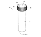
次に、アングルロータ1の収容穴10aに挿入され収容される遠心分離機用培養遠心管20について説明する。遠心分離機用培養遠心管20は、図4及び図5に示されるように、管容器21とキャップ22とを備え、これらはポリカーボネートからなり、インジェクション成形によって成形されて構成される。管容器21は筒状をなしており、一端が塞がれて底部21Aをなし、底部21Aは先端が切取られた円錐形状をなす。管容器21の他端は開口部21Bをなす。管容器21は、その開口部21Bがキャップ22によって塞がれた状態で、アングルロータ1の収容穴10aに挿入されて、管容器21内に注入された液体試料3の遠心分離が行われる。
【0039】
管容器21は、底部21Aから開口部21Bに向かってわずかに拡径している。管容器21の外周であって開口部21Bの開口端21Eから離間した位置には、鋸歯状の雄ねじ部21Cが設けられており、キャップ22に設けられた後述の雌ねじ部22Fと螺合可能に構成されている。図2又は図5に示されるように、管容器21の開口端21E近傍の位置であって、雄ねじ部21Cの最も開口端21Eに近い位置から開口端21Eにかけての位置の内径は、開口端21Eへ向かって徐々に拡径しており拡径部21Dをなす。このため、後述のキャップ22の環状溝22aに、管容器21の開口端21E近傍の部分を容易に挿入することができる。管容器21内には液体試料3が注入される。管容器21の内面は、図5に示されるように凹凸のないなめらかな曲面をなす。このため、液体試料3を遠心分離した後に残留する沈殿物の取出し操作等を容易に行うことができる。
【0040】
キャップ22は、板状の円盤部22Aと環状部22Bとを備える。円盤部22Aは、円盤部22Aを規定する一方の面22C、他方の面22D共に平坦であり円形状をなし、肉厚が一定である。環状部22Bは、円形をした円盤部22Aの一方の面22Cの周囲から円盤部22Aの軸方向に延出して設けられており、環状部22Bの内周であって、環状部22Bの円盤部22Aとの接続位置から離間した位置には、鋸歯状の雌ねじ部22Fを有している。円盤部22Aは、環状部22Bの軸心に対して垂直をなす。
【0041】
ここで、一般には雌ねじ部のねじ溝に連なる環状部22Bの内周面側には、製作上の理由で内径が大きくなる方向に逃げ溝が形成されることがあるが、本実施の形態では逃げ溝は形成されない。このような逃げ溝は空洞をなすため、遠心分離中に培養遠心管20に遠心力が働いたときに、逃げ溝に培養遠心管20の開口端21Eが入込んで変形する可能性があるからである。
【0042】
円盤部22Aの一方の面22Cの側であって円盤部22Aと環状部22Bとの境界位置には、環状溝22aが形成されている。環状溝22aは、円盤部22Aの環状部22Bの軸方向に向かって形成されており、管容器21の開口部21Bが嵌合可能に構成されている。環状溝22aの開口端22bは円盤部22Aの一方の面22Cに一致している。環状溝22aを画成する環状部22Bの内周であって環状部22Bの円盤部22Aとの接続位置近傍の部分22Gは、図2に示されるように、管容器21の開口端21E近傍の部分の形状に略倣った形状となっており、キャップ22の剛性と相まって、キャップ22により管容器21の開口部21Bが塞がれ管容器21の開口端21E近傍の部分が環状溝22aに嵌合したときに、開口端21E近傍位置と環状部22Bの接続位置近傍とは、これらの間に空洞が形成されない密着状態となるように構成されている。
【0043】
換言すれば、環状溝22aの内周面側をリップ部とみなしたとき、リップ部の内周面側に円盤部22Aが一体に設けられることによってリップ部が補強され、ポリカーボネートからなる材質と相まって、管容器21の開口端21E近傍位置に対する密着を確保する構成及び材質になっている。ここでキャップ22は、所定の厚さを有しており、キャップ22の環状溝22aの内周面と環状溝22aに嵌合した管容器21の開口部21Bとの密着を確保するのに十分な剛性を備える構成及び材質になっており、また、キャップ22の環状溝22aの外周面と環状溝22aに嵌合した開口部21Bとの密着を確保するのに十分な剛性を備える構成及び材質になっている。
【0044】
キャップ22により管容器21の開口部21Bが塞がれたときに、開口端21E近傍位置と環状部22Bの接続位置近傍とが密着状態となるため、遠心分離機用培養遠心管20に入った液体試料3を振とう培養器で培養する際や、ユーザが持ち運んだりするときに、液体試料3が遠心分離機用培養遠心管20から漏れることを確実に防止できる。また、遠心分離を行っているときに、従来のように、管容器の開口部やキャップに変形が生じたり、キャップが開口部から外れたりすることを防止することができる。
【0045】
環状部22Bの軸方向における円盤部22Aの他方の面22Dの高さは、図2に示されるように、円盤部22Aと接続されている環状部22Bの基端部22Hの高さよりも低くなっており、円盤部22Aの肉厚は、前述の剛性を備えるに足りるだけの厚さとなっている。このため、キャップ22を製造する材料を必要最小限とすることができ、キャップ22を含めた遠心分離機用培養遠心管20のコストを低減することができる。また、キャップ22の軽量化を図ることができる。
【0046】
また、キャップ22の環状部22Bの外周には、図4に示されるように、環状部22Bの軸方向に延びる溝22cが複数形成されている。このため、ユーザが指でキャップ22を摘み、キャップ22を管容器21に対して回して管容器21の開口部21Bを塞ぐときに、ユーザの指がキャップ22に対して滑ることを防止できる。
【0047】
再びアングルロータ1の説明に戻るが、アングルロータ1に形成され遠心分離機用培養遠心管20に倣った形状の収容穴10aは、収納穴に挿入される遠心分離機用培養遠心管20の外形よりも若干大きく構成されている。より具体的には管収容部10fは、管容器21全体を収容・支持できるように管容器21に対して相似形状をなしており、収納穴に遠心分離機用培養遠心管20が挿入されているときに、収容穴10aの半径方向における管収容部10fと管容器21との間には、0.1mm〜0.5mm程度のギャップが形成されている。
【0048】
このため、液体試料3の入った管容器21が遠心分離されたときに、液体試料3の液圧によって管容器21が膨張するのを極力抑止することができ、管容器21の膨張を、管容器21を構成するプラスチックの伸びの特性上問題がない範囲に収めることができる。また、培養遠心管20の収容穴10aへの着脱を容易とすることができる。また、収容穴10aが、遠心分離機用培養遠心管20に倣った形状となっているため、管容器21の底部21Aに対向する収容穴10aの底部10hも底部21Aに倣った形状となっている。このため、遠心力による液圧によって培養遠心管20が変形するのを極力抑止することができる。
【0049】
また、キャップ収容部10gは、キャップ22の一部を収容・支持できるように、キャップの22の一部を受け入れ可能な穴としている。キャップ収容部10gは、具体的には、キャップ22の環状部22Bの自由端22Iから、基端部22Hへと向かった所定の位置に至るまでの部分の領域22e(図2)をその全周にわたり取囲む略円柱形状をなしており、環状部22Bの軸方向における当該領域22eの長さは、図2の右下方に示されるように、キャップ22の環状部22Bの軸方向長さの略75%である。なお、図2の左上方に位置するキャップ22の環状部22Bの部分の当該領域22eは、キャップ22の環状部22Bの軸方向長さの100%になっているように見えるが、これはこの部分に限ったことであり全周にわたってはいない。
【0050】
収容穴10aの半径方向におけるキャップ収容部10gとキャップ22との間には0.1mm〜0.3mm程度のギャップが形成される。このため、遠心分離を行っているときに、キャップ22の変形を防止するようにしっかりとキャップ22を支持することが可能である。
【0051】
収容穴10aの軸方向における、収容穴10aの管収容部10fとキャップ収容部10gとの接続位置10i(図2)から管収容部10fの底部10h(図1)までの距離は、収容穴10aへ遠心分離機用培養遠心管20をセットしたときの、管容器21の軸方向における、キャップ22の環状部22Bの自由端22Iから管容器21の底部21Aまでの距離よりも小さい。このため、培養管遠心管が収容穴10aに挿入されるセット時には、キャップ22の自由端22Iと当該接続位置10iとの間に若干のギャップが形成される。
【0052】
前述のように、収容穴10aの半径方向における管収容部10fと管容器21との間には、0.1mm〜0.5mm程度のギャップが形成されているので、培養遠心管20の管容器21は遠心分離中に液圧を受けて膨張するが、その結果として培養遠心管20の軸方向に縮む。このとき、キャップ22の自由端22Iと当該接続位置10iとの間に若干のギャップが形成されているため縮み代を吸収し、キャップ22の自由端22Iと当該接続位置10iとが互いに当接するのを防ぐことができる。
【0053】
キャップ22の自由端22Iと当該接続位置10iとが互いに当接してしまうと、遠心力により管容器21が管収容部10fの底部10hの方へ引っ張られて、キャップ22が管容器21から引き剥がされるような力が発生するのであるが、互いに当接することを防止することができるため、このような力の発生を防止することができ、キャップ22が管容器21から外れてしまうのを防止することができる。従って、培養遠心管20のセット時におけるギャップの値は、収容穴10aの管収容部10fと管容器21とのギャップによって決まる管容器21の軸方向の縮み代によって決定される。
【0054】
本発明による遠心分離機用培養遠心管20は、上述した実施の形態に限定されず、特許請求の範囲に記載した範囲で種々の変形や改良が可能である。例えば本実施の形態では、円盤部22Aは一方の面22C、他方の面22D共に平坦であったが、図6に示されるように、円盤部32Aの他方の面32Dには、持ち手31を円盤部32Aと一体に設けてもよい。この構成により、ロータボディ10の収容穴10aへの遠心分離機用培養遠心管30の着脱を工具を用いずに行うことができる。
【0055】
また、キャップ22の環状部22Bの自由端22Iから基端部22Hへと向かった所定の位置に至るまでの部分の領域22eの、キャップ22の環状部22Bの軸方向における長さは、キャップ22の環状部22Bの軸方向長さの略75%であったが、この値に限定されない。但し、図7に示されるように、キャップ収容部40gに対向する当該領域の軸方向長さを40%以上とする必要がある。40%以上とすることによって、アングルロータ1′の回転中に、遠心力や液体試料の液圧によってキャップが回転軸心の半径方向外方に移動したり、変形したりすることを防止する効果を十分発揮することができる。
【0056】
これは、キャップとキャップ収容部40gとの間のギャップが小さいため、キャップの回転軸心の半径方向外方への移動を、キャップ収容部40gの内壁が阻止できるからである。そして、40%以上とすることによって、キャップ収容部40gから露出するキャップの部分が多くなり、当該部分をユーザが指で摘むことが可能となり、収容穴10a′への培養遠心管20の着脱を容易にすることができる。
【0057】
また、管容器21の底部21Aは、先端が切取られた円錐形状をなしていたが、この形状に限定されず、例えば、半球状であってもよい。
【0058】
また、遠心分離機用培養遠心管20を構成する管容器21とキャップ22とは、ポリカーボネートにより構成されたが、これに限定されず、例えばポリプロピレンやポリスチレン等のプラスチックにより構成されてもよい。
【0059】
また、環状部22Bの軸方向における円盤部22Aの他方の面22Dの高さは、円盤部22Aと接続されている環状部22Bの基端部22Hの高さよりも低くなっていたが、高さを一致させてもよい。この構成により、キャップの製造を容易とすることができる。
【0060】
また、管容器21に形成された雄ねじ部21C、キャップ22に形成された雌ねじ部22Fは、それぞれ鋸歯状をしていたが、これに限定されず、例えば、通常の正三角形のねじ形状であってもよい。
【0061】
また、収納穴に遠心分離機用培養遠心管20が挿入されているときに、収容穴10aの管収容部10fと遠心分離機用培養遠心管20との間に0.1mm〜0.5mm程度のギャップが形成されていたが、伸びが少ないプラスチックにより管容器21が構成される場合は、このギャップをもっと小さな値とする。
【0062】
また、雌ねじ部22Fのねじ溝の底部には逃げ溝は形成されていなかったが、巾の小さい逃げ溝であれば形成されてもよい。
【0063】
【発明の効果】
請求項1記載の遠心分離機用培養遠心管によれば、円盤部と環状部との間には環状溝が形成され、キャップの円盤部の軸方向長さは環状溝の軸方向長さと略同じとされ、キャップは、環状溝の内周と環状溝に嵌合した管容器の開口部との密着を確保するのに十分な剛性を備えるため、従来の遠心分離機用培養遠心管と同様の材質、製造方法で容易かつ安価に製造した遠心分離機用培養遠心管を用いて遠心分離を行っているときに、キャップの環状溝の内周面と環状溝に嵌合した管容器の開口部との密着を維持することができる。このため、遠心分離を行っている間中、管容器のキャップによる密封を維持することができる。
【0064】
請求項3記載の遠心分離機用培養遠心管によれば、環状部の軸方向における円盤部の他方の面の高さは、円盤部と接続されている環状部の基端部の高さに一致しているため、キャップの製造を容易とすることができる。
【0065】
請求項4記載の遠心分離機用培養遠心管によれば、環状部の軸方向における円盤部の他方の面の高さは、円盤部と接続されている環状部の基端部の高さよりも低いため、キャップを製造する材料の量を、所望の剛性を維持するために必要な最小限の量とすることができ、キャップを含めた遠心分離機用培養遠心管のコストを低減することができる。また、キャップの軽量化を図ることができる。
【0066】
【0067】
【0068】
【0069】
【0070】
請求項5記載の遠心分離機用培養遠心管によれば、開口部の開口端近傍の位置の内径は、開口端へ向かって徐々に拡径しているため、キャップの環状溝に、管容器の開口端近傍の位置を容易に挿入することができる。
【図面の簡単な説明】
【図1】 本実施の形態によるアングルロータを示す部分断面図。
【図2】 図1の円IIで囲まれた部分の拡大図。
【図3】 本実施の形態によるアングルロータを示す斜視図。
【図4】 本実施の形態による遠心分離機用培養遠心管を示す斜視図。
【図5】 本実施の形態による遠心分離機用培養遠心管を示す部分断面図。
【図6】 本実施の形態の変形例による遠心分離機用培養遠心管を示す斜視図。
【図7】 本実施の形態の変形例によるアングルロータを示す要部断面図。
【図8】 従来の遠心分離機用培養遠心管及びアングルロータを示す要部断面図。
【図9】 従来の遠心分離機用培養遠心管を示す断面図。
【図10】 従来の遠心分離機用培養遠心管を示す断面図。
【図11】 従来の遠心分離機用培養遠心管の、遠心分離を行っている状態を示す要部断面図。
【符号の説明】
1・・・アングルロータ 3・・・液体試料 10a・・・収容穴 10f・・・管収容部 10g・・・キャップ収容部 10h・・・底部 20、30・・・遠心分離機用培養遠心管 21・・・管容器 21A・・・底部 21B・・・開口部 21C・・・雄ねじ部 21D・・・拡径部 22、32・・・キャップ 22A・・・円盤部 22B・・・環状部 22C・・・一方の面 22D、32D・・・他方の面 22F・・・雌ねじ部 22H・・・基端部 22I・・・自由端 22a・・・環状溝 22c・・・溝 22e・・・領域 31・・・持ち手[0001]
BACKGROUND OF THE INVENTION
The present invention provides a culture for a centrifugeCentrifuge tubeIn particular, disposable cultures used in centrifuges such as high-speed cooling centrifuges and small high-speed centrifuges used in the fields of medicine, chemistry, pharmacy, genetic engineering, etc.Centrifuge tubeAbout.
[0002]
[Prior art]
Centrifugal separators such as high-speed cooling centrifuges and small high-speed centrifuges include an angle rotor that is drivingly connected to a motor, and the angle rotor is rotated by driving the motor. The angle rotor holds a culture centrifuge tube into which a liquid sample to be centrifuged is injected, and rotates under atmospheric pressure or low vacuum. In this type of centrifuge, the maximum rotation speed is about 5,000 to 14,000 / min, the maximum centrifugal acceleration is about 25,000 G, and various angle rotors are manufactured according to the application.
[0003]
As the angle rotor, R12A5 type, R10A2 type, T11A21 type, T9A31 type rotor manufactured by Hitachi Koki Co., Ltd., TA22 type, TA23 type rotor manufactured by Tommy Seiko Co., Ltd., etc. are commercially available. These angle rotors are generally made of an aluminum alloy, and the solid body of the aluminum alloy is machined to drive a receiving hole for receiving a culture centrifuge tube or a drive shaft that is connected to a motor. A shaft hole is formed and an angle rotor is manufactured.
[0004]
The culture centrifuge tube held by the angle rotor is called a culture tube, a centrifuge tube for tissue culture, a centrifuge tube, a tissue culture tube (TC tube), or the like, and forms a container for a sample to be centrifuged. Various products such as Sumitomo Bakelite Co., Ltd., Asahi Techno Glass Co., Ltd. and Assist Co., Ltd. are sold as centrifugal culture tubes. In a centrifugal culture tube, plastics such as polypropylene and polystyrene are used for both the culture tube container and the cap, and are manufactured by injection molding. Centrifugal culture tubes are supplied at low cost because they are consumed in large quantities due to disposable use, and are used as containers when culturing cells. Used by setting to an angle rotor.
[0005]
More specifically, as shown in FIG. 8, the
[0006]
The centrifuge
[0007]
The
[0008]
As shown in FIG. 9, the
[0009]
In addition to the centrifuge
[0010]
As publicly known documents showing the technical level of culture centrifuge tubes for centrifuges, there are JP-A-9-299813, JP-A-5-9653, and JP-A-7-151661. Japanese Patent Laid-Open No. 9-299813 describes a dialysis container having a container body and a lid. The container body and the lid are detachably coupled to each other by screws provided on the outer peripheral surface or inner peripheral surface of the upper end portion. In Japanese Utility Model Laid-Open No. 5-9653, the outer peripheral surface of the open end of the tube corresponding to the tube container is tapered, and the position corresponding to the outer peripheral surface of the open end is a part of the plug corresponding to the cap. Describes a sealing structure of a plastic tube for a centrifuge in which the opening end of the tube and the plug are in close contact with each other. Japanese Patent Application Laid-Open No. 7-151661 describes a phase separation tube having openings at both one end and the other end.
[0011]
[Patent Document 1]
Japanese Patent Laid-Open No. 9-299813 (
[Patent Document 2]
Japanese Utility Model Publication No. 5-9653 (first page, FIG. 1)
[Patent Document 3]
Japanese Patent Laid-Open No. 7-151661 (
[0012]
[Problems to be solved by the invention]
The time taken for centrifugation is inversely proportional to the centrifugal acceleration of the angle rotor. Therefore, in order to shorten the time required for centrifugation, it is conceivable to increase the centrifugal acceleration by increasing the centrifugal rotation speed. In general, cultured cells do not lose activity or die even when loaded to about 50,000 G. Therefore, it can be considered simply to increase the centrifugal rotation speed until a load of about 50,000 G is applied, thereby shortening the time required for the centrifugal separation.
[0013]
However, in the conventional centrifuge
[0014]
The mechanism by which this phenomenon occurs isas belowIt is. First, before centrifugation is performed, a predetermined amount of
[0015]
The centrifuge
[0016]
When the
[0017]
At this time, in the
[0018]
In addition, among the conventional angle rotors, there is an angle rotor having a configuration different from the configuration shown in FIGS. 8 and 11 and having no stepped portion. In this case, the centrifugal separation is performed with the
[0019]
As described above, in the
[0020]
Accordingly, the present invention is a culture that is inexpensive, easy to handle, has high rigidity and strength, and can withstand high centrifugal acceleration.Centrifuge tubeThe purpose is to provide.
[0021]
[Means for Solving the Problems]
In order to achieve the above object, the present invention provides:underThe end is closed and the bottom is formedUpThe end is not openHowever, the outer periphery of the opening is not provided with a screw portion, and the outer periphery of the opening is provided with a male screw portion.A plastic tube container, a disk part and a disk partUpFrom an annular part extending in the axial direction of the disk part from the periphery of the surfaceComposedTheAn annular groove is formed between the disk portion and the annular portion, and an internal thread portion that is threadedly engaged with the external thread portion of the tube container is provided on the inner periphery of the annular portion, and the plastic that closes the opening portion of the tube container With caps made of,Liquid sample injectedThe upper end of the opened opening of the tube container is abutted against the annular groove of the capThe liquid sample is inserted into the receiving hole formed in the angle rotor of the centrifuge while the male screw part is screwed into the female screw part and the opening is closed by the cap. Culture centrifuge tube for centrifugeSoAndThe depth of the annular groove is such that the upper end opening in which the male threaded portion of the tube container is not formed can be inserted, and the inner circumference of the annular groove and the inner circumference of the annular portion of the cap. A circumference and an outer circumference are formed, and the axial length of the disk portion of the cap is substantially the same as the axial length of the annular groove, and the cap is fitted to the inner circumference of the annular groove and the annular groove. Provide sufficient rigidity to ensure close contact with the opening of the tube containerA culture centrifuge tube for a centrifuge is provided.Here, it is preferable that a hollow portion is not formed between the lower end of the annular groove and the upper end of the male screw portion and between the inner periphery of the annular portion of the cap and the outer periphery of the tube container.
[0022]
Also,It is preferable that the height of the other surface of the disk part in the axial direction of the annular part matches the height of the base end part of the annular part connected to the disk part.
[0023]
Alternatively, the height of the other surface of the disk part in the axial direction of the annular part is preferably lower than the height of the base end part of the annular part connected to the disk part.
[0024]
[0025]
[0026]
[0027]
[0028]
Moreover, it is preferable that the internal diameter of the position near the opening end of the opening gradually increases toward the opening end.
[0029]
[0030]
[0031]
[0032]
DETAILED DESCRIPTION OF THE INVENTION
Centrifuge culture according to embodiments of the inventionCentrifuge tubeWill be described with reference to FIGS. As shown in FIG. 1, the angle rotor 1 provided in the centrifuge includes a
[0033]
The
[0034]
An
[0035]
The
[0036]
The
[0037]
When centrifugal separation is performed, after inserting a centrifuge
[0038]
Next, the centrifuge
[0039]
The
[0040]
The
[0041]
Here, in general, an escape groove may be formed on the inner peripheral surface side of the
[0042]
An
[0043]
In other words, when the inner peripheral surface side of the
[0044]
When the
[0045]
As shown in FIG. 2, the height of the
[0046]
Further, as shown in FIG. 4, a plurality of
[0047]
Returning to the description of the angle rotor 1 again, the
[0048]
For this reason, when the
[0049]
Further, the cap
[0050]
A gap of about 0.1 mm to 0.3 mm is formed between the
[0051]
In the axial direction of the
[0052]
As described above, since a gap of about 0.1 mm to 0.5 mm is formed between the
[0053]
When the free end 22I of the
[0054]
Centrifuge culture according to the present inventionCentrifuge tube 20Is not limited to the above-described embodiment, and various modifications and improvements can be made within the scope described in the claims. For example, in the present embodiment, the
[0055]
In addition, the length in the axial direction of the
[0056]
This is because the gap between the cap and the cap
[0057]
Further, the bottom 21A of the
[0058]
Moreover, although the
[0059]
In addition, the height of the
[0060]
Further, the
[0061]
Further, when the centrifuge
[0062]
Moreover, although the escape groove was not formed in the bottom part of the thread groove of the
[0063]
【The invention's effect】
According to the culture centrifuge tube for a centrifuge according to claim 1,An annular groove is formed between the disk portion and the annular portion, the axial length of the disk portion of the cap is substantially the same as the axial length of the annular groove, and the cap is formed on the inner periphery and the annular groove of the annular groove. Provide sufficient rigidity to ensure close contact with the fitted tube container openingTherefore, when the centrifuge culture centrifuge tube manufactured easily and inexpensively with the same material and manufacturing method as the conventional centrifuge culture centrifuge tube is used, Adhesion between the peripheral surface and the opening of the tube container fitted in the annular groove can be maintained. For this reason, the sealing by the cap of the tube container can be maintained during the centrifugation.
[0064]
Claim 3According to the described culture centrifuge tube for a centrifuge, the height of the other surface of the disk part in the axial direction of the annular part matches the height of the base end part of the annular part connected to the disk part. Therefore, the cap can be easily manufactured.
[0065]
Claim 4According to the described centrifuge culture centrifuge tube, the height of the other surface of the disc portion in the axial direction of the annular portion is lower than the height of the proximal end portion of the annular portion connected to the disc portion, The amount of material from which the cap is made can be the minimum amount necessary to maintain the desired stiffness, and the cost of the centrifuge culture centrifuge tube including the cap can be reduced. Moreover, the weight of the cap can be reduced.
[0066]
[0067]
[0068]
[0069]
[0070]
Claim 5According to the described culture centrifuge tube for a centrifuge, the inner diameter of the opening portion in the vicinity of the opening end gradually increases toward the opening end.,The position near the opening end of the tube container can be easily inserted into the annular groove of the cap.
[Brief description of the drawings]
FIG. 1 is a partial cross-sectional view showing an angle rotor according to an embodiment.
FIG. 2 is an enlarged view of a portion surrounded by a circle II in FIG.
FIG. 3 is a perspective view showing an angle rotor according to the present embodiment.
FIG. 4 is a perspective view showing a culture centrifuge tube for a centrifuge according to the present embodiment.
FIG. 5 is a partial sectional view showing a culture centrifuge tube for a centrifuge according to the present embodiment.
FIG. 6 is a perspective view showing a culture centrifuge tube for a centrifuge according to a modification of the present embodiment.
FIG. 7 is a cross-sectional view of a main part showing an angle rotor according to a modification of the embodiment.
FIG. 8 is a cross-sectional view of a main part showing a conventional culture centrifuge tube and an angle rotor for a centrifuge.
FIG. 9 is a cross-sectional view showing a conventional culture centrifuge tube for a centrifuge.
FIG. 10 is a cross-sectional view showing a conventional culture centrifuge tube for a centrifuge.
FIG. 11 is a cross-sectional view of a main part showing a state in which a conventional culture centrifuge tube for a centrifuge is being centrifuged.
[Explanation of symbols]
DESCRIPTION OF SYMBOLS 1 ...
Claims (5)
円盤部と該円盤部の上面の周囲から該円盤部の軸方向に延出する環状部とから構成され、該円盤部と該環状部との間には環状溝が形成され、該環状部の内周に該管容器の該雄ねじ部に螺合する雌ねじ部が設けられ、該管容器の開口部を塞ぐプラスチック製のキャップとを備え、
液体試料が注入された該管容器の開口部の上端を該キャップの該環状溝に突き当て、該雄ねじ部が該雌ねじ部に螺合することにより該開口部が該キャップによって塞がれた状態で、遠心分離機のアングルロータに形成された収容穴に挿入されて該液体試料の遠心分離を行うための遠心分離機用培養遠心管であって、
該環状溝の深さは該管容器の該雄ねじ部が形成されていない上端開口部を挿入可能な深さとされていると共に該キャップの該円盤部外周及び該環状部内周により該環状溝の内周及び外周が形成され、該キャップの該円盤部の軸方向長さは該環状溝の軸方向長さと略同じとされ、該キャップは、該環状溝の内周面と該環状溝に嵌合した該管容器の開口部との密着を確保するのに十分な剛性を備えることを特徴とする遠心分離機用培養遠心管。 It upper end forms a bottom lower end is blocked the name of the opening, a plastic tube externally threaded portion is provided below the outer circumference of the opening not threaded portion is provided in the opening periphery A container,
Consists from the periphery of the upper surface of the disk portion and the disc-portion and an annular portion extending axially of the disc-portion, between the said disc portion and the annular portion is formed an annular groove, the annular portion A female screw part that is screwed into the male screw part of the tube container is provided on the inner periphery of the tube container, and includes a plastic cap that closes the opening of the tube container ,
A state in which the upper end of the opening of the tube container into which the liquid sample has been injected is abutted against the annular groove of the cap, and the male threaded portion is screwed into the female threaded portion so that the opening is closed by the cap in, and are inserted into the receiving hole formed in centrifuge angle rotor met centrifuge culture centrifuge tube for centrifuging the liquid sample,
The depth of the annular groove is such that the upper end opening in which the male threaded portion of the tube container is not formed can be inserted, and the inner circumference of the annular groove and the inner circumference of the annular portion of the cap. A circumference and an outer circumference are formed, and the axial length of the disk portion of the cap is substantially the same as the axial length of the annular groove, and the cap is fitted to the inner circumferential surface of the annular groove and the annular groove. A culture centrifuge tube for a centrifuge having sufficient rigidity to ensure close contact with the opening of the tube container .
Priority Applications (2)
| Application Number | Priority Date | Filing Date | Title |
|---|---|---|---|
| JP2003105177A JP4465976B2 (en) | 2002-04-26 | 2003-04-09 | Culture centrifuge tube for centrifuge |
| US10/422,852 US7214177B2 (en) | 2002-04-26 | 2003-04-25 | Culture tube and angle rotor receiving the tube in centrifuge |
Applications Claiming Priority (2)
| Application Number | Priority Date | Filing Date | Title |
|---|---|---|---|
| JP2002126586 | 2002-04-26 | ||
| JP2003105177A JP4465976B2 (en) | 2002-04-26 | 2003-04-09 | Culture centrifuge tube for centrifuge |
Publications (3)
| Publication Number | Publication Date |
|---|---|
| JP2004000192A JP2004000192A (en) | 2004-01-08 |
| JP2004000192A5 JP2004000192A5 (en) | 2006-04-20 |
| JP4465976B2 true JP4465976B2 (en) | 2010-05-26 |
Family
ID=29253650
Family Applications (1)
| Application Number | Title | Priority Date | Filing Date |
|---|---|---|---|
| JP2003105177A Expired - Lifetime JP4465976B2 (en) | 2002-04-26 | 2003-04-09 | Culture centrifuge tube for centrifuge |
Country Status (2)
| Country | Link |
|---|---|
| US (1) | US7214177B2 (en) |
| JP (1) | JP4465976B2 (en) |
Families Citing this family (9)
| Publication number | Priority date | Publication date | Assignee | Title |
|---|---|---|---|---|
| JP3863465B2 (en) * | 2002-07-17 | 2006-12-27 | 株式会社久保田製作所 | centrifuge |
| DE102004062231B4 (en) * | 2004-12-23 | 2012-12-13 | Thermo Electron Led Gmbh | Rotor for laboratory centrifuges |
| JP2007222037A (en) * | 2006-02-22 | 2007-09-06 | Sumitomo Bakelite Co Ltd | Cell-culturing and centrifuging tube |
| US8231070B2 (en) * | 2006-05-26 | 2012-07-31 | Northeastern University | Devices, methods and applications for extraction of molecules from polymeric gel electrophoretic media |
| WO2009017765A1 (en) * | 2007-07-30 | 2009-02-05 | Peter Florez | Disposable mini-bioreactor device and method |
| JP5592080B2 (en) * | 2009-05-08 | 2014-09-17 | 株式会社日立製作所 | Cell culture method and cell culture system |
| CN103721772B (en) * | 2012-10-16 | 2015-08-12 | 杭州爱菩高特生物技术有限公司 | Multi-functional centrifuge tube box with cover |
| CA3080649A1 (en) * | 2017-10-30 | 2019-05-09 | Nanjingjinsirui Science & Technology Biology Corp. | Inclined magnetic holder |
| CN111420812B (en) * | 2020-03-02 | 2021-08-13 | 重庆医科大学附属永川医院 | Centrifugal machine |
Family Cites Families (21)
| Publication number | Priority date | Publication date | Assignee | Title |
|---|---|---|---|---|
| US2813650A (en) * | 1955-12-30 | 1957-11-19 | American Cyanamid Co | Bottle closure |
| US2965256A (en) * | 1959-04-10 | 1960-12-20 | Donald E Yochem | Closure for a container |
| US3366320A (en) * | 1965-07-21 | 1968-01-30 | Atomic Energy Commission Usa | Centrifuge sample holder |
| US3456876A (en) * | 1966-03-23 | 1969-07-22 | Beckman Instruments Inc | Apparatus and articles for increasing the rate of particle separation and removal |
| US3540612A (en) * | 1969-02-17 | 1970-11-17 | Bio Dynamics Inc | Bottle cap and bottle combination |
| US3881627A (en) * | 1973-05-09 | 1975-05-06 | Ethyl Dev Corp | Vial container and closure |
| US4469235A (en) * | 1983-09-14 | 1984-09-04 | Kerr Glass Manufacturing Corporation | Closure with upwardly extending tabs |
| US4537320A (en) * | 1983-10-27 | 1985-08-27 | Nielsen Steven T | Centrifuge tube having removable crown and swage fitting |
| US4690670A (en) * | 1986-01-10 | 1987-09-01 | Nielsen Steven T | Centrifuge tube having reusable seal |
| US5100013A (en) * | 1990-01-29 | 1992-03-31 | Extrudiplast Investments, S.A. | Plastic closure |
| GB9012041D0 (en) * | 1990-05-30 | 1990-07-18 | Beeson & Sons Ltd | Improvements in or relating to containers |
| US5460283A (en) * | 1991-01-25 | 1995-10-24 | Macartney; Charles T. | Sealing closure cap |
| JPH059653U (en) | 1991-07-24 | 1993-02-09 | 日立工機株式会社 | Sealed structure of plastic tube for centrifuge |
| DE4139810C2 (en) * | 1991-12-03 | 1995-03-09 | Eppendorf Geraetebau Netheler | Lid jar |
| CA2094317C (en) * | 1993-04-19 | 2003-01-07 | Victor Daykin | Biological specimen collection system |
| US5389265A (en) | 1993-06-02 | 1995-02-14 | E. I. Du Pont De Nemours And Company | Phase-separation tube |
| US5358129A (en) * | 1993-06-24 | 1994-10-25 | Mcneil-Ppc, Inc. | Child resistant bottle |
| JPH09299813A (en) | 1996-05-10 | 1997-11-25 | Toshihiko Kuroda | Container for dialysis |
| EP1429972A2 (en) * | 2001-09-28 | 2004-06-23 | Gen-Probe Incorporated | Closure system |
| JP3863465B2 (en) * | 2002-07-17 | 2006-12-27 | 株式会社久保田製作所 | centrifuge |
| JP2004188346A (en) * | 2002-12-12 | 2004-07-08 | Asahi Techno Glass Corp | Self supporting centrifuge tube |
-
2003
- 2003-04-09 JP JP2003105177A patent/JP4465976B2/en not_active Expired - Lifetime
- 2003-04-25 US US10/422,852 patent/US7214177B2/en not_active Expired - Lifetime
Also Published As
| Publication number | Publication date |
|---|---|
| US20030203800A1 (en) | 2003-10-30 |
| JP2004000192A (en) | 2004-01-08 |
| US7214177B2 (en) | 2007-05-08 |
Similar Documents
| Publication | Publication Date | Title |
|---|---|---|
| US7118522B2 (en) | Centrifuge adapter | |
| JP4465976B2 (en) | Culture centrifuge tube for centrifuge | |
| US6730510B2 (en) | Culture dish and bioreactor system | |
| US10434522B2 (en) | Fixed angle centrifuge rotor having torque transfer members and annular containment groove | |
| JP6136509B2 (en) | Centrifuge, centrifuge rotor and centrifuge sample container | |
| US20110319247A1 (en) | Centrifuge sample container and centrifuge | |
| JP5923127B2 (en) | Centrifuge container, centrifuge, and centrifuge method using them | |
| JP3863465B2 (en) | centrifuge | |
| JP4329207B2 (en) | Centrifuge rotor and centrifuge | |
| US11759794B2 (en) | Centrifuge sample container, centrifuge rotor using same, and centrifuge | |
| JP2702693B2 (en) | Centrifuge rotor | |
| CN112469505A (en) | Centrifuge rotor and container arrangement | |
| JPH0624652B2 (en) | Cavity seal device for centrifuge rotor | |
| AU2021257782A1 (en) | Devices and methods for portable and compact centrifugation | |
| EP4015009A1 (en) | Waste liquid receiving receptacle, waste liquid reservoir comprising same, and waste liquid suction system | |
| JP2014198281A (en) | Container for centrifugal separation, centrifugal separator and centrifugal separation method using them | |
| JPH09155235A (en) | Swing rotor for centrifuge and centrifugal separation | |
| JP3159874U (en) | Centrifugal adapter and centrifugal device | |
| US11447318B2 (en) | Wax ring tray and method of use | |
| JPH09155236A (en) | Adapter for microplate | |
| CA1327557C (en) | Plasma separator | |
| JP2004267858A (en) | Centrifuge and swing rotor for centrifuge |
Legal Events
| Date | Code | Title | Description |
|---|---|---|---|
| A521 | Request for written amendment filed |
Free format text: JAPANESE INTERMEDIATE CODE: A523 Effective date: 20060306 |
|
| A621 | Written request for application examination |
Free format text: JAPANESE INTERMEDIATE CODE: A621 Effective date: 20060306 |
|
| A131 | Notification of reasons for refusal |
Free format text: JAPANESE INTERMEDIATE CODE: A131 Effective date: 20090310 |
|
| A521 | Request for written amendment filed |
Free format text: JAPANESE INTERMEDIATE CODE: A523 Effective date: 20090508 |
|
| TRDD | Decision of grant or rejection written | ||
| A01 | Written decision to grant a patent or to grant a registration (utility model) |
Free format text: JAPANESE INTERMEDIATE CODE: A01 Effective date: 20100202 |
|
| A01 | Written decision to grant a patent or to grant a registration (utility model) |
Free format text: JAPANESE INTERMEDIATE CODE: A01 |
|
| A61 | First payment of annual fees (during grant procedure) |
Free format text: JAPANESE INTERMEDIATE CODE: A61 Effective date: 20100215 |
|
| R150 | Certificate of patent or registration of utility model |
Ref document number: 4465976 Country of ref document: JP Free format text: JAPANESE INTERMEDIATE CODE: R150 Free format text: JAPANESE INTERMEDIATE CODE: R150 |
|
| FPAY | Renewal fee payment (event date is renewal date of database) |
Free format text: PAYMENT UNTIL: 20130305 Year of fee payment: 3 |
|
| FPAY | Renewal fee payment (event date is renewal date of database) |
Free format text: PAYMENT UNTIL: 20140305 Year of fee payment: 4 |
|
| FPAY | Renewal fee payment (event date is renewal date of database) |
Free format text: PAYMENT UNTIL: 20140305 Year of fee payment: 4 |
|
| FPAY | Renewal fee payment (event date is renewal date of database) |
Free format text: PAYMENT UNTIL: 20150305 Year of fee payment: 5 |
|
| S533 | Written request for registration of change of name |
Free format text: JAPANESE INTERMEDIATE CODE: R313533 |
|
| R350 | Written notification of registration of transfer |
Free format text: JAPANESE INTERMEDIATE CODE: R350 |
|
| S111 | Request for change of ownership or part of ownership |
Free format text: JAPANESE INTERMEDIATE CODE: R313111 |
|
| R350 | Written notification of registration of transfer |
Free format text: JAPANESE INTERMEDIATE CODE: R350 |
|
| R250 | Receipt of annual fees |
Free format text: JAPANESE INTERMEDIATE CODE: R250 |
|
| R250 | Receipt of annual fees |
Free format text: JAPANESE INTERMEDIATE CODE: R250 |
|
| R250 | Receipt of annual fees |
Free format text: JAPANESE INTERMEDIATE CODE: R250 |
|
| EXPY | Cancellation because of completion of term |