JP4461715B2 - Image forming apparatus and image forming method - Google Patents
Image forming apparatus and image forming method Download PDFInfo
- Publication number
- JP4461715B2 JP4461715B2 JP2003159979A JP2003159979A JP4461715B2 JP 4461715 B2 JP4461715 B2 JP 4461715B2 JP 2003159979 A JP2003159979 A JP 2003159979A JP 2003159979 A JP2003159979 A JP 2003159979A JP 4461715 B2 JP4461715 B2 JP 4461715B2
- Authority
- JP
- Japan
- Prior art keywords
- image
- color
- image forming
- mark
- scanning direction
- Prior art date
- Legal status (The legal status is an assumption and is not a legal conclusion. Google has not performed a legal analysis and makes no representation as to the accuracy of the status listed.)
- Expired - Fee Related
Links
Images


Landscapes
- Electrostatic Charge, Transfer And Separation In Electrography (AREA)
- Control Or Security For Electrophotography (AREA)
- Color Electrophotography (AREA)
- Fax Reproducing Arrangements (AREA)
- Laser Beam Printer (AREA)
Description
【0001】
【発明の属する技術分野】
この発明は中間転写ベルト又は感光体ベルトを有したタンデム型のカラープリンタや複写機、これらの複合機等に適用して好適な画像形成装置及び画像作成方法に関するものである。
【0002】
【従来の技術】
近年、タンデム型のカラープリンタや複写機、これらの複合機等が使用される場合が多くなってきた。これらのカラー画像形成装置ではイエロー(Y)、マゼンタ(M)、シアン(C)、黒(BK)色用の各々の露光手段、現像装置、感光体ドラムと、中間転写ベルト及び定着装置とを備えている。
【0003】
例えば、Y色用の露光手段では任意の画像情報に基づいて感光体ドラムに静電潜像を描くようになされる。現像装置では感光体ドラムに描かれた静電潜像にY色用のトナーを付着してカラートナー像を形成する。感光体ドラムはトナー像を中間転写ベルトに転写する。他のM、C、BK色についても同様の処理がなされる。中間転写ベルトに転写されたカラートナー像は用紙に転写された後に定着装置によって定着される。
【0004】
ところで、この種のカラー画像形成装置によれば、中間転写ベルトに色ずれ無くカラートナー像を形成しなければならない。色ずれ無く重ね合わされたカラートナー像を用紙に転写するためである。
【0005】
図54は従来例に係るカラーレジストマーク検知例を示す図である。図54において、中間転写ベルト(ベルトユニット又は紙搬送ベルトとも呼ばれる)6には任意の画像情報に基づく色画像を形成する前に定期又は不定期に「カラーレジストマーク検知」と呼ばれる処理がなされる。この検知処理では反射型のフォトセンサ(以下でレジストセンサともいう)12Aや12Bなどを用いて中間転写ベルト6上の「フ」字状のカラーレジストマーク(以下で単にカラーレジストマークCRともいう)がアナログ電圧として検出される。
【0006】
このとき、フォトセンサ12A等から出射した光は例えば、中間転写ベルト6上のカラーレジストマークCRによって吸収や、拡散がなされる。この処理では中間転写ベルト6から反射してくる光を検出することによりカラーレジストマークCRのマーク位置(エッジ又は重心)を検出するようになされる。エッジ検出データはRAM等に記録され、その後、その記録を基にしてY、M、C、BK色の各色ずれ量を算出し、この色ずれ量を無くすようにトナー像を重ね合わせるような各色毎に露光手段が調整される。
【0007】
図55はレジストセンサ12A等による傷に係る信号例を示す波形図である。図55において、横軸は時間tであり、縦軸はレジストセンサ12A等による位置検出信号S2の信号レベルである。図55に示す実線はカラーレジスト形成前の中間転写ベルト6の色画像形成面の状態を表す波形である。Lbは位置検出信号S2のベース補正レベルである。Lthは閾値である。
【0008】
この波形は中間転写ベルト6を一周回してレジストセンサ12A等により、色画像形成面を検出することにより得られる。カラーレジストマーク検知処理の妨げ有無は閾値Lthを下回る信号レベルが存在するか否かによって判断される。図55に示す信号例によれば、閾値Lthに至る位置検出信号S2が検出されており、中間転写ベルト6にカラーレジストマーク検知処理の妨げとなるこすれ傷等が有る場合である。傷は画像形成装置動作中に停電して中間転写ベルト6が急停止したドラム1とこすれた場合や、メンテナンス時の中間転写ベルト6の出し入れの際に生ずることがある。
【0009】
なお、特許文献1には、レーザビーム複写機及びファクシミリ装置に適用可能な電子写真方式の画像形成装置が開示されている。この画像形成装置によれば、像担持体を露光して品質の良い画像を形成するために補正手段が備えられる。補正手段では、各像担持体から搬送体に転写されたレジストマーク画像のうち、搬送体搬送方向で最下流側に位置する像担持体から搬送体に転写されたレジストマーク画像の検出タイミングと、残る他の各レジストマーク画像の検出タイミングとの相対差分が検出される。
【0010】
この相対差分に基づいて、補正手段は、残る各像担持体への光ビームの照射開始タイミング、その像担持体への光ビームの照射角度(スキューに対する調整)、及び、画素クロックの周期調整で倍率を調整するようになされる。つまり、特許文献1によれば、各色のレジストマークを搬送体に作成し、レジストセンサでレジストマークの通過タイミングを検出し、基準色に対する他色の位置ずれ量を算出して画像形成位置を補正するようになされる。
【0011】
【特許文献1】
特開平01−142681号公報(第13頁 第4図)
【0012】
【発明が解決しようとする課題】
ところで、従来方式のタンデム型のカラー画像形成装置によれば、以下のような問題がある。
【0013】
i. 特許文献1を含むカラーレジストマークの検知処理において、中間転写ベルト6の経時的な変化、例えば、ベルトの材質によっても異なるがベルト面のこすれ傷等により、ベルト面の反射光量が低くなって、カラーレジストマークCRとの信号差を十分に確保することが困難となってくる。特に、カラーレジストマークCRの濃度が変動した場合、つまり、濃度が薄くなった場合や、濃度が高くなりすぎた場合等において、反射光量が高くなって(正反射成分が増えて)しまうので、濃度変動によりカラーレジストマークが再現性よく検出できなくなるおそれがある。
【0014】
ii. 上述した中間転写ベルト6の経時的な変化によって、そのベルトに傷(耐久傷)が増えてくると、ベルト傷等にセンサが反応してしまい、カラーレジストマーク(以下で印画像ともいう)のマークエッジを正確に検出できない場合が多くなってくる。因みに予め黒色の帯を中間転写ベルト6の色画像形成面に作成し、その後、この黒色形成面上に各色のレジストマークを作成する方法が考えられるが、トナー消費量が多くなる。
【0015】
iii. カラーレジストマーク検知処理において、上述のi.及びii.に対応して、各色毎にレジストマーク画像の濃度が適切に調整されていないと、正確な色ずれ量を算出できなくなったり、また、レジストセンサ12A等から得られる位置検出信号S2を最適な閾値Lthを用いないで演算処理すると、正確なレジストマーク画像の検出タイミングが得られなくなってしまう。
【0016】
そこで、この発明は上述した課題を解決したものであって、画像転写系の使用環境が経時的に変化した場合であっても、本来の印画像の位置を正確に検出できるようにすると共に、高信頼度の位置検出信号に基づいて色画像の形成位置を精度良く調整できるようにした画像形成装置及び画像作成方法を提供することを目的とする。
【0024】
【課題を解決するための手段】
上記課題を解決するために、本発明の請求項1に係る画像形成装置は、任意のカラー用の画像情報に基づいて色画像を形成する装置であって、像形成体を有して画像情報に基づいて色を重ね合わせ色画像を形成する画像形成手段と、この画像形成手段によって形成された色画像の位置を検出する検出手段と、この検出手段の出力に基づいて画像形成手段を制御する制御装置とを備え、像形成体の幅方向を主走査方向とし、当該主走査方向に直交する方向を副走査方向とし、主走査方向に平行な線画及び副走査方向に直交しない斜線画を組み合わせて構成されるトナー像を印画像とし、主走査方向及び副走査方向に各々所定のパターン幅を有し、かつ、印画像の全体を取り囲む矩形状のパターンを有して構成され、矩形状のパターン内において、印画像が色抜け部分を成すようにトナー像を形成する範囲が反転されたトナー像を反転印画像としたとき、制御装置は、少なくとも、予め色重ね合わせ用の印画像を反転した二以上の反転印画像を像形成体の副走査方向に並べて形成し、当該像形成体に形成される一方の反転印画像の下部と、他方の反転印画像の上部とを重なるように画像形成手段を制御すると共に、この画像形成手段で形成された反転印画像の色抜け部分が成す印画像の位置検出に基づいて色画像の形成位置を調整するように当該画像形成手段を制御することを特徴とするものである。
【0025】
請求項1に係る画像形成装置によれば、任意の画像情報に基づいて色を重ね合わせ色画像を形成する場合に、例えば、画像形成手段を構成する画像形成ユニットによって画像転写手段に色画像が形成される。この画像転写手段に形成された色画像の位置は検出手段によって検出される。制御装置では検出手段の出力に基づいて画像転写手段又は画像形成ユニットを制御するようになされる。
【0026】
これを前提にして、制御装置では予め色重ね合わせ用の印画像を反転した二以上の反転印画像を像形成体の副走査方向に並べて形成し、当該像形成体に形成される一方の反転印画像の下部と、他方の反転印画像の上部とを重なるように画像形成手段を制御すると共に、この画像形成手段で形成された反転印画像の色抜け部分が成す印画像の位置検出に基づいて色画像の形成位置を調整するように当該画像形成手段を制御するようになる。
【0027】
従って、印画像を成す色抜け部分以外を反転印画像により覆い隠すことができるので、メンテナンスや部品消耗等の経時的な変化により画像転写手段に傷等が生じた場合であっても、本来の印画像の位置を正確に検出することができる。これにより、傷等による雑音信号が重畳されない高信頼度の位置検出信号に基づいて色画像の形成位置を精度良く調整することができる。
【0028】
本発明の請求項12に係る画像形成方法は任意の画像情報に基づいて像形成体に色を重ね合わせて色画像を形成する方法であって、像形成体の幅方向を主走査方向とし、前記主走査方向に直交する方向を副走査方向とし、主走査方向に平行な線画及び副走査方向に直交しない斜線画を組み合わせて構成されるトナー像を印画像とし、主走査方向及び副走査方向に各々所定のパターン幅を有し、かつ、印画像の全体を取り囲む矩形状のパターンを有して構成され、矩形状のパターン内において、印画像が色抜け部分を成すようにトナー像を形成する範囲が反転されたトナー像を反転印画像としたとき、予め色重ね合わせ用の印画像を反転するための反転印画像情報が準備され、画像形成装置が、反転印画像情報に基づいて像形成体の副走査方向に二以上の反転印画像を並べて形成すると共に、当該像形成体に形成される一方の反転印画像の下部と、他方の反転印画像の上部とを重なるように形成し、像形成体に形成された反転印画像の色抜け部分が成す印画像の位置を検出し、色抜け部分が成す印画像の位置に基づいて色画像の形成位置を調整することを特徴とするものである。
【0029】
請求項12に係る画像形成方法によれば、色抜け部分が印画像を成す反転印画像を画像転写系や像形成体等に再現性良く形成できるので、メンテナンス等の際に画像転写系に不本意に生じた傷等をこの反転印画像によって覆い隠すことができる。
【0030】
また、画像転写系や像形成体等に傷等が生じた場合であっても、本来の印画像の位置を正確に検出できるので、傷等による雑音信号が重畳されない高信頼度の位置検出信号に基づいて色画像の形成位置を精度良く調整することができる。従って、画像転写系で正確に色を重ね合わせることができるので、所望の転写紙に色画像を精度良く転写することができる。
【0031】
本発明の請求項22に係る画像形成装置は任意のカラー用の画像情報に基づいて色画像を形成する装置であって、像形成体を有して画像情報に基づいて色を重ね合わせ色画像を形成する画像形成手段と、この画像形成手段によって形成された色画像の位置を検出する検出手段と、この検出手段の出力に基づいて画像形成手段を制御する制御装置とを備え、像形成体の幅方向を主走査方向とし、主走査方向に平行な線画及び副走査方向に直交しない斜線画を組み合わせて構成されるトナー像を印画像とし、主走査方向及び副走査方向に各々所定のパターン幅を有し、かつ、印画像の全体を取り囲む矩形状のパターンを有して構成され、矩形状のパターン内において、印画像が色抜け部分を成すようにトナー像を形成する範囲が反転されたトナー像を反転印画像としたとき、制御装置は、少なくとも、画像形成手段の使用状況に応じて、色重ね合わせ用の印画像又は該印画像を反転した二以上の反転印画像を像形成体の副走査方向に並べて形成し、当該像形成体に形成される一方の反転印画像の下部と、他方の反転印画像の上部とを重なるように画像形成手段で形成し、この画像形成手段で形成された印画像又は反転印画像の色抜け部分が成す印画像の位置検出に基づいて色画像の形成位置を調整するように画像形成手段を制御することを特徴とするものである。
【0032】
請求項22に係る画像形成装置によれば、任意の画像情報に基づいて色を重ね合わせ色画像を形成する場合に、例えば、画像形成手段を構成する画像形成ユニットでは画像転写手段に色画像が形成される。位置検出用の検出手段では画像転写手段に形成された色画像の位置が検出される。制御装置では検出手段の出力に基づいて画像転写手段又は画像形成ユニットが制御される。
【0033】
これを前提にして、制御装置では少なくとも、画像転写手段の使用状況に応じて色重ね合わせ用の印画像又は該印画像を反転した反転印画像を画像転写手段に形成し、この画像転写手段に形成された印画像又は反転印画像の色抜け部分が成す印画像の位置検出に基づいて色画像の形成位置を調整するように画像形成ユニットを制御するようになる。
【0034】
従って、画像形成手段を構成する画像転写手段や像形成体等を新規に使用する場合や、当該画像転写手段が新品と交換された場合等は、印画像の位置検出に基づいて色画像の形成位置を調整することができる。メンテナンスや部品消耗等の経時的な変化により画像転写手段に傷等が生じた場合は、反転印画像により傷等を覆い隠すことができるので、本来の印画像の位置を正確に検出することができる。
【0035】
これにより、傷等による雑音信号が重畳されない高信頼度の位置検出信号に基づいて色画像の形成位置を精度良く調整することができる。
【0036】
本発明の請求項41に係る画像形成方法は、任意の画像情報に基づいて像形成体に色を重ね合わせた色画像を形成する方法であって、像形成体の幅方向を主走査方向とし、主走査方向に直交する方向を副走査方向とし、主走査方向に平行な線画及び副走査方向に直交しない斜線画を組み合わせて構成されるトナー像を印画像とし、主走査方向及び副走査方向に各々所定のパターン幅を有し、かつ、印画像の全体を取り囲む矩形状のパターンを有して構成され、矩形状のパターン内において、印画像が色抜け部分を成すようにトナー像を形成する範囲が反転されたトナー像を反転印画像としたとき、色重ね合わせ用の印画像を形成するための印画像情報又は該印画像を反転した反転印画像を形成するための反転印画像情報が予め準備され、その後、画像形成装置が、像形成体の色画像形成面の表面状態を検出し、色画像形成面の表面状態に応じて印画像情報に基づく印画像を像形成体に形成し、又は、反転印画像情報に基づいて像形成体の副走査方向に二以上の反転印画像を並べて形成すると共に、当該像形成体に形成される一方の反転印画像の下部と、他方の反転印画像の上部とを重なるように形成し、像形成体に形成された印画像又は反転印画像の色抜け部分が成す印画像の位置検出に基づいて色画像の形成位置を調整することを特徴とするものである。
【0037】
請求項41に係る画像形成方法によれば、例えば、画像形成系において、画像転写系や像形成体等を新規に使用する場合や、当該画像転写系が新品と交換された場合等は、印画像の位置検出に基づいて色画像の形成位置を調整することができる。メンテナンスや部品消耗等の経時的な変化により画像転写系に傷等が生じた場合は、反転印画像により傷等を覆い隠すことができるので、本来の印画像の位置を正確に検出することができる。
【0038】
従って、傷等による雑音信号が重畳されない高信頼度の位置検出信号に基づいて色画像の形成位置を精度良く調整することができる。これにより、画像転写手段に正確に色を重ね合わせることができるので、所望の転写紙に色画像を精度良く転写することができる。
【0042】
従って、各色毎に最適な制御基準値を見つけだすことができ、色ずれ補正モード時に、本来の印画像の位置を正確に検出することができ、高信頼度の位置検出信号に基づいて印画像の形成位置を精度良く調整することができる。これにより、画像形成系や画像転写系等で正確に色を重ね合わせることができるので、所望の転写紙に色画像を精度良く転写することができる。
【0045】
従って、画像転写系や像形成体等における反射光量の変動や、センサ発光量の低減等により使用環境が経時的な変化した場合であっても、最適な制御基準値を見出すことができるので、色ずれ補正モード時に、本来の印画像の位置を正確に検出することができ、高信頼度の位置検出信号に基づいて印画像の形成位置を精度良く調整することができる。これにより、画像形成系や画像転写系等で正確に色を重ね合わせることができるので、所望の転写紙に色画像を精度良く転写することができる。
【0046】
【発明の実施の形態】
以下、図面を参照しながら、この発明の実施形態に係る画像形成装置及び画像作成方法について説明をする。
(1)第1の実施形態
図1は、本発明の各実施形態としてのカラー画像形成装置100の構成例を示す概念図である。
この実施形態では、色画像の濃度検出系や位置検出系の出力に基づいて画像転写手段又は画像形成ユニットを制御する制御装置を備え、この制御装置では色画像の位置検出系で色濃度補正用の切片画像の濃度を検出し、当該位置検出系から出力される切片画像の濃度検出信号に基づいて印画像の位置検出用の制御基準値を校正し、画像転写手段における反射光量の変動や、センサ発光量の低減等により画像転写手段の使用環境が経時的に変化した場合であっても、本来の印画像の位置を正確に検出できるようにすると共に、高信頼度の位置検出信号に基づいて色画像の形成位置を精度良く調整できるようにしたものである。
【0047】
図1に示すカラー画像形成装置100は第1〜第3の画像形成装置の一例を構成するものであり、任意の画像情報に基づいて色を重ね合わせ、画像転写系に色画像を形成する装置である。
【0048】
図1において、カラー画像形成装置100は、画像形成装置本体101と画像読取装置102とから構成される。画像形成装置本体101の上部には、自動原稿給紙装置201と原稿画像走査露光装置202から成る画像読取装置102が設置されている。自動原稿給紙装置201の原稿台上に載置された原稿dは搬送手段により搬送され、原稿画像走査露光装置202の光学系により原稿の片面又は両面の画像が走査露光され、ラインイメージセンサCCDに読み込まれる。
【0049】
ラインイメージセンサCCDにより光電変換されたアナログ信号は、図示しない画像処理部において、アナログ処理、A/D変換、シェーディング補正及び画像圧縮処理等がなされ、画像情報となる。その後、画像情報は画像形成ユニットの一例となる画像書き込み部(露光手段)3Y、3M、3C、3Kへ送られる。
【0050】
自動原稿給紙装置201は自動両面原稿搬送手段を備えている。この自動原稿給紙装置201は原稿載置台上から給送される多数枚の原稿dの内容を連続して一挙に読み取り、原稿内容を記憶手段に蓄積するようになされる(電子RDH機能)。この電子RDH機能は、複写機能により多数枚の原稿内容を複写する場合、或いはファクシミリ機能により多数枚の原稿dを送信する場合等に便利に使用される。
【0051】
画像形成装置本体101は、タンデム型カラー画像形成装置と称せられるもので、複数組の画像形成ユニット(画像形成系)10Y、10M、10C、10Kと、画像転写手段(画像転写系)の一例を成す中間転写体としての無終端状の中間転写ベルト6と、再給紙機構(ADU機構)を含む給紙搬送手段と、トナー像を定着するための定着装置17からなる。
【0052】
イエロー(Y)色の画像を形成する画像形成ユニット10Yは、像形成体としての感光体ドラム1Yと、感光体ドラム1Yの周囲に配置されたY色用の帯電手段2Y、露光手段3Y、現像装置4Y及び像形成体用のクリーニング手段8Yを有する。マゼンタ(M)色の画像を形成する画像形成ユニット10Mは、像形成体としての感光体ドラム1Mと、M色用の帯電手段2M、露光手段3M、現像装置4M及び像形成体用のクリーニング手段8Mを有する。
【0053】
シアン(C)色の画像を形成する画像形成ユニット10Cは、像形成体としての感光体ドラム1Cと、C色用の帯電手段2C、露光手段3C、現像装置4C及び像形成体用のクリーニング手段8Cを有する。黒(BK)色の画像を形成する画像形成ユニット10Kは、像形成体としての感光体ドラム1Kと、BK色用の帯電手段2K、露光手段3K、現像装置4K及び像形成体用のクリーニング手段8Kを有する。
【0054】
帯電手段2Yと露光手段3Y、帯電手段2Mと露光手段3M、帯電手段2Cと露光手段3C及び帯電手段2Kと露光手段3Kとは、潜像形成手段を構成する。現像装置4Y、4M、4C、4Kによる現像は、使用するトナー極性と同極性(本実施形態においては負極性)の直流電圧に交流電圧を重畳した現像バイアスが印加される反転現像にて行われる。中間転写ベルト6は、複数のローラにより巻回され、回動可能に支持されている。
【0055】
画像形成プロセスの概要について以下に説明する。画像形成ユニット10Y、10M、10C及び10Kより形成された各色の画像は、使用するトナーと反対極性(本実施形態においては正極性)の1次転写バイアス(不図示)が印加される1次転写ローラ7Y、7M、7C及び7Kにより、回動する中間転写ベルト6上に逐次転写されて(1次転写)、合成されたカラー画像(色画像:カラートナー像)が形成される。カラー画像は中間転写ベルト6から用紙Pへ転写される。
【0056】
給紙カセット20A、20B、20C内に収容された用紙Pは、給紙カセット20A、20B、20Cにそれぞれ設けられる送り出しローラ21および給紙ローラ22Aにより給紙され、搬送ローラ22B、22C、22D、レジストローラ23等を経て、2次転写ローラ7Aに搬送され、用紙P上の一方の面(表面)にカラー画像が一括して転写される(2次転写)。
【0057】
カラー画像が転写された用紙Pは、定着装置17により定着処理され、排紙ローラ24に挟持されて機外の排紙トレイ25上に載置される。転写後の感光体ドラム1Y、1M、1C、1Kの周面上に残った転写残トナーは、像形成体クリーニング手段8Y、8M、8C、8Kによりクリーニングされ次の画像形成サイクルに入る。
【0058】
両面画像形成時には、一方の面(表面)に画像形成され、定着装置17から排出された用紙Pは、分岐手段26によりシート排紙路から分岐され、それぞれ給紙搬送手段を構成する、下方の循環通紙路27Aを経て、再給紙機構(ADU機構)である反転搬送路27Bにより表裏を反転され、再給紙搬送部27Cを通過して、給紙ローラ22Dにおいて合流する。
【0059】
反転搬送された用紙Pは、レジストローラ23を経て、再度2次転写ローラ7Aに搬送され、用紙Pの他方の面(裏面)上にカラー画像(カラートナー像)が一括転写される。カラー画像が転写された用紙Pは、定着装置17(或いは定着装置17A)により定着処理され、排紙ローラ24に挟持されて機外の排紙トレイ25上に載置される。一方、2次転写ローラ7Aにより用紙Pにカラー画像を転写した後、用紙Pを曲率分離した中間転写ベルト6は、中間転写ベルト用のクリーニング手段8Aにより残留トナーが除去される。
【0060】
これらの画像形成の際には、用紙Pとして52.3〜63.9kg/m2(1000枚)程度の薄紙や64.0〜81.4kg/m2(1000枚)程度の普通紙や83.0〜130.0kg/m2(1000枚)程度の厚紙や150.0kg/m2(1000枚)程度の超厚紙を用い、線速度を80〜350mm/sec程度とし、環境条件として温度が5〜35℃程度、湿度が15〜85%程度の設定条件とすることが好ましい。用紙Pの厚み(紙厚)としては0.05〜0.15mm程度の厚さのものが用いられる。
【0061】
上述のクリーニング手段8Aの上流側であって、中間転写ベルト6の左側には、第1の検出手段の一例となるトナー像濃度検知用のセンサ(以下、単にトナー濃度センサ11という)が設けられており、中間転写ベルト6に形成されたトナー像(色画像)の濃度を検出し、濃度検出信号S1を発生するようになされる。
【0062】
このトナー濃度センサに並べて第2の検出手段の一例となるトナー像位置ずれ検知用のセンサ(以下、単にレジストセンサ12という)が設けられており、中間転写ベルト6に形成された印画像(以下でカラーレジストマークCRという)の位置を検出し、位置検出信号S2を発生するようになされる。画像形成装置本体101には制御装置15が設けられ、位置検出信号S2に基づいてカラーレジストマーク検知処理をするようになされる。
【0063】
カラーレジストマーク検知処理とは色重ね合わせ用のカラーレジストマークCRを中間転写ベルト6に形成し、この中間転写ベルト6に形成されたカラーレジストマークCRの位置(エッジ、重心等)をレジストセンサ12によって検出することをいう。この処理はカラーレジストマークCRの位置に基づいて色画像の形成位置を調整するためである。この例では、中間転写ベルト6の使用環境が経時的に変化した場合であっても、本来のカラーレジストマークCRの位置を正確に検出できるようにすると共に、高信頼度の位置検出信号S2に基づいて色画像の形成位置を精度良く調整できるようになされる。
【0064】
図2は本発明に係る第1の実施形態としてのカラー画像形成装置100の画像転写及び画像形成系の構成例を示すブロック図である。図2に示すカラー画像形成装置100は図1に示した中間転写ベルト6を画像転写系Iとし、画像形成ユニット10Y,10M,10C,10Kを画像形成系IIとして抜き出したものである。図2において、カラー画像形成装置100は制御装置15を有している。制御装置15にはトナー濃度センサ11が接続されており、中間転写ベルト6に形成されたトナー像(色画像)の濃度を検出し、濃度検出信号S1を制御装置15へ出力するようになされる。
【0065】
制御装置15にはトナー濃度センサ11の他にレジストセンサ12が接続されており、中間転写ベルト6に形成されたトナー像(色画像)の位置を検出して位置検出信号S2を制御装置15へ出力するようになされる。制御装置15はレジストセンサ12から得られる位置検出信号S2に基づいて画像形成ユニット10Y,10M,10Cを制御するようになされる。この例で制御装置15は、画像形成ユニット10Y,10M,10Cにおける補正手段5Y,5M,5Cを通じて、主/副走査時の書き出し位置調整及び画像書込み部3Y,3M,3Cにおける位置調整(スキュー調整)、主走査書込みクロック信号の補正(横倍調整/部分横倍調整)等がなされる(図3参照)。
【0066】
制御内容によっては画像形成ユニット10Kを基準にして画像形成ユニット10Y,10M,10Cのいずれか一方又は3つを制御するようにしてもよい。制御装置15の負担を軽減できる。もちろん、中間転写ベルト6を制御対象に入れてもよい。その場合には、図示しない蛇行補正機構を設け、中間転写ベルト6の蛇行を補正して色ずれを調整するようにしてもよい。
【0067】
制御装置15には画像形成ユニット10Y,10M,10C,10Kが接続されており、画像形成ユニット10Yでは、任意の画像情報Dinを構成するY色用の画像情報Dy、主走査方向のY色書込み周期用のH−VALID信号(以下Y−HV信号という)、副走査方向のY色書込み周期用のH−VALID信号(以下Y−VV信号という)、Y色用のポリゴン駆動クロック信号(以下でYポリゴンCLKという)を入力し、画像情報Dy、Y−HV信号、Y−VV信号、YポリゴンCLKに基づいて中間転写ベルト6にY色のトナー画像を形成する。
【0068】
画像形成ユニット10MではM色用の画像情報Dm、主走査方向のM色書込み周期用のH−VALID信号(以下M−HV信号という)、副走査方向のM色書込み周期用のH−VALID信号(以下M−VV信号という)、M色用のポリゴン駆動クロック信号(以下でMポリゴンCLKという)を入力し、画像情報Dm、M−HV信号、M−VV信号、MポリゴンCLKに基づいて中間転写ベルト6にM色のトナー画像を形成する。
【0069】
画像形成ユニット10CではC色用の画像情報Dc、主走査方向のC色書込み周期用のH−VALID信号(以下C−HV信号という)、副走査方向のC色書込み周期用のH−VALID信号(以下C−VV信号という)、C色用のポリゴン駆動クロック信号(以下でCポリゴンCLKという)を入力し、画像情報Dc、C−HV信号、C−VV信号、CポリゴンCLKに基づいて中間転写ベルト6にC色のトナー画像を形成する。
【0070】
画像形成ユニット10KではBK色用の画像情報Dk、主走査方向のBK色書込み周期用のH−VALID信号(以下K−HV信号という)、副走査方向のBK色書込み周期用のH−VALID信号(以下K−VV信号という)、BK色用のポリゴン駆動クロック信号(以下でKポリゴンCLKという)を入力し、画像情報Dk、K−HV信号、K−VV信号、KポリゴンCLKに基づいて中間転写ベルト6にBK色のトナー画像を形成するようになされる。
【0071】
この例ではY色用の画像書き込み部(露光手段)3Yには補正手段5Yが取り付けられており、制御装置15からのY色用の位置補正信号Syに基づいてY色画像の主走査方向の形成位置を調整するようになされる。同様にしてM色用の画像書き込み部3Mには補正手段5Mが取り付けられており、制御装置15からのM色用の位置補正信号Smに基づいてM色画像の主走査方向の形成位置を調整するようになされる。
【0072】
C色用の画像書き込み部3Cには補正手段5Cが取り付けられており、制御装置15からのC色用の位置補正信号Scに基づいてY色画像の主走査方向の形成位置を調整するようになされる。BK色用の画像書き込み部3Kには補正手段5Kが取り付けられており、制御装置15からのBK色用の位置補正信号Skに基づいてBK色画像の主走査方向の形成位置を調整するようになされる(部分横倍率補正)。この例で色ずれ量の算出に関しては、BK色のカラーレジストマークCRを基準にしている。Y,M,C色の色画像の書込み位置をBK色に合わせるように調整するためである。
【0073】
例えば、Y色の書込み位置調整に関しては、BK色のカラーレジストマークCRの書込み位置と、Y色のカラーレジストマークCRの書込み位置とを検知し、Y色のカラーレジストマークCRの書込み位置をBK色のカラーレジストマークCRの書込み位置に換算した際のずれ量からその補正量を算出する。同様にして、M、C色の書込み位置調整に関しても、BK色のカラーレジストマークCRの書込み位置と、MやC色のカラーレジストマークCRの書込み位置とのずれ量を各々検知し、このずれ量から各々の補正量を算出する。その後、BK色用の画像形成ユニット10K以外のY、M、C色用の画像ユニット10Y,10M,10Cを調整するようになされる。
【0074】
このため、BK色用の画像形成ユニット10Kでは中間転写ベルト6に対してBK色のみの出力で正規の主/副走査時の書き込み位置調整及び画像書込み部3Kにおける横倍調整、部分横倍調整及び傾き調整等がなされる。BK色について調整し基準とするためである。その後、本発明方式のカラーレジスト調整に移行してBK色に合わせてY,M,C色の書込み位置を合わせるレジスト調整を実行するようになされる。
【0075】
また、制御装置15では切片画像の一例となる色濃度補正用のパッチマークを中間転写ベルト6に形成するように画像形成ユニット10Y,10M,10Cが制御される。中間転写ベルト6に形成されたパッチマークの濃度はレジストセンサ12によって検出される。その後、パッチマークの濃度に基づいて色重ね合わせ用のカラーレジストマークCRの濃度が調整され、ここで濃度調整されたカラーレジストマークCRを中間転写ベルト6に形成するように制御装置15によって画像形成ユニット10Y,10M,10C,10Kが制御される。
【0076】
中間転写ベルト6に形成されたカラーレジストマークCRの位置はレジストセンサ12によって検出される。制御装置15ではレジストセンサ12から出力されるパッチマークの濃度情報を含む位置検出信号S2’に基づいてカラーレジストマークCRの位置検出時の閾値Lthをリアルタイムに校正できるようになる。このカラーレジストマークCRの位置に基づいて色画像の形成位置を調整するように画像形成ユニット10Y,10M,10C,10Kを制御するようになされる。
【0077】
この例では、レジストセンサ12から出力されるパッチマークの非形成部分の位置検出信号S2’の最小値(MIN)及び当該パッチマークの形成部分に係る最大値(MAX)を検出し、この濃度情報を含む位置検出信号S2’の最小値及び最大値に基づいて平均値を演算する。
【0078】
この演算ではパッチマークの非形成部分に係る濃度情報を含む位置検出信号S2’の最大値及びその形成部分に係る最小値が演算対象から除かれる。すなわち、パッチマークが形成されていない中間転写ベルト(ベース)6の反射出力の値と、パッチマークを形成した部分の反射出力の値とが最も近い場合の値が2値化する閾値を決める最悪の関係となる。
【0079】
このため、その条件となる値を使用して平均値(中央値)を割り出し、2値化の閾値を決定するようになされる。この例では、当該平均値をレジストセンサ12の制御基準値とし、この制御基準値に基づいてカラーレジストマークCRの通過タイミングを検出するようになされる。レジストセンサ12の制御基準値は平均値近傍であってもよい。
【0080】
もちろん、これに限られることはなく、同一シーケンス内で制御装置15により、色濃度補正用のパッチマークを中間転写ベルト6に形成し、中間転写ベルト6に形成されたパッチマークの濃度をトナー濃度センサ11によって検出し、色画像の濃度を調整する色補正処理を実行すると共に、中間転写ベルト6に形成されたパッチマークの濃度をレジストセンサ12により連続して検出してもよい。パッチ検出時に生成されるパッチマークをレジストセンサ12で連続して検出することで、最も信号レベルが確保できるカラーレジストマークCRの濃度を決めることができる。
【0081】
その後は、パッチマークの濃度に基づいてカラーレジストマークCRを中間転写ベルト6に形成し、中間転写ベルト6に形成されたカラーレジストマークCRの位置をレジストセンサ12によって検出し、カラーレジストマークCRの位置に基づいて色画像の形成位置を調整する色重ね合わせ処理をするようになされる。
【0082】
図3は制御装置15の位置ずれ制御系に係る内部構成例を示すブロック図である。図3に示す制御装置15は発振器51、分周器52、ポリゴン駆動回路53、計数回路54、CPU(中央演算装置)55、ラッチ回路56、RAM57、ディジタル/アナログ(D/A)変換器58、二値化用のコンパレータ59、インデックス遅延回路510、VV生成回路511、HV生成回路512、スキュー補正回路513、アナログ/ディジタル(A/D)変換器514及びマスク生成回路515等を有している。
【0083】
発振器51では基準周波数のクロック信号CKを発生するようになされる。発振器51には分周器52が接続されており、クロック信号CKを分周して所定の周波数のシステムクロック信号SCKを生成するようになされる。
【0084】
分周器52にはポリゴン駆動回路53及び計数回路54が接続されている。ポリゴン駆動回路53ではCPU55からの回転位相設定信号Srに基づいて、システムクロック信号SCKからYポリゴンCLK、MポリゴンCLK、CポリゴンCLK及びKポリゴンCLKが各々の生成される。YポリゴンCLKは画像書き込み部3Yに出力され、MポリゴンCLKは画像書き込み部3Mに出力され、CポリゴンCLKは画像書き込み部3Cに出力され、及び、KポリゴンCLKは画像書き込み部3Kに出力される。
【0085】
計数回路54ではCPU55からの画像先端信号(以下VTOP信号という)をリセット信号としてシステムクロック信号SCKをカウントしてラッチ信号SLを発生するようになされる。VTOP信号はBK色の書込み位置を検出する際の基準となる。ラッチ信号SLはBK、Y、M、C色の書込み位置を示すものとなる。例えば、BK色の書込み位置はVTOP信号が立ち上がった時刻を基準にしてシステムクロック信号SCKをカウントすることで認識される。
【0086】
計数回路54にはラッチ回路56が接続されており、マスク後の通過タイミングパルス信号Spに基づいてラッチ信号SLをラッチするようになされる。ラッチ回路56にはRAM57が接続されており、RAM57をロードするようになされる。RAM57はデータバス16を通じてCPU55に接続される。
【0087】
一方、図2に示したレジストセンサ12はコンパレータ59に接続される。コンパレータ59にはD/A変換器58が接続され、CPU55からの閾値設定データDthをディジタル/アナログ変換して閾値Lthを発生する。コンパレータ59ではレジストセンサ12からの位置検出信号S2が閾値(制御基準値)Lthに基づいて二値化される。この例では使用環境に応じて最適に閾値Lthを校正するようになされる。二値化後の位置検出信号S2は通過タイミングパルス信号Spとなる。
【0088】
コンパレータ59にはマスク回路515が接続されており、印画像以外の通過タイミングパルス信号Spをマスクするようになされる。マスク回路515にはラッチ回路56が接続されており、印画像以外をマスクされた通過タイミングパルス信号Spに基づいてラッチ信号SLを制御するようになされる。
【0089】
また、レジストセンサ12にはA/D変換器514に接続され、パッチマークを当該レジストセンサ12で検出して得た濃度情報を含む位置検出信号S2’がアナログ/ディジタル変換される。A/D変換後の濃度検出データD1’はCPU55へ出力される。CPU55では濃度検出データD1’に基づいて閾値設定データDthが決定される。この閾値設定データDthを使用することで、カラーレジストマークCRの位置検出時の閾値Lthをリアルタイムに校正できるようになる。
【0090】
インデックス遅延回路(以下で横倍補正部ともいう)510はCPU55に接続されており、上位の制御システムから供給されるY,M,C,BKの各色用のINDEX(クロック)信号を遅延制御データD10に基づいて遅延し可変して、Y,M,C,BKの各色用の遅延INDEX信号(delay YINDEX、delay MINDEX、delay CINDEX、delay KINDEX)を画像転送系Iへ出力するようになされる。
【0091】
VV生成回路(以下で副走査補正部ともいう)511はCPU55に接続されており、副走査方向の書込み周期用のV−VALID(以下VVという)生成制御データD11に基づいてY,M,C,BKの各色の副走査周期信号であるY−VV、M−VV,C−VV,K−VV信号を各々生成し、これらのY−VV、M−VV,C−VV,K−VV信号を画像形成系IIへ出力するようになされる。Y−VV、M−VV,C−VV,K−VV信号の立ち上がりによって副走査方向の書込みが開始される。
【0092】
HV生成回路(以下で主走査補正部ともいう)512はCPU55に接続されており、主走査方向の書込み周期用のH−VALID(以下HVという)生成制御データD12に基づいてY,M,C,BKの各色の主走査周期信号であるY−HV、M−HV,C−HV,K−HV信号を各々生成し、これらのY−HV、M−HV,C−HV,K−HV信号を画像形成系IIへ出力するようになされる。Y−HV、M−HV,C−HV,K−HV信号の立ち上がりによって主走査方向の書込みが開始される。
【0093】
スキュー補正回路(以下でスキュー補正部ともいう)513はCPU55に接続されており、画像傾き補正用のスキュー補正データD13に基づいてY,M,Cの各色のスキュー補正信号S13(Y,M,C)を生成し、このY,M,Cの各色の信号S13(Y,M,C)を画像形成系IIへ出力するようになされる。スキュー補正回路513にはY、M、Cの各色用の画像書込み部3Y、3M、3Cに設けられたモータ9Y,9M,9Cが接続されており、例えば、スキュー補正信号S13(Y)に基づいて画像書込み部3Y等の姿勢を調整される。又は、これらの姿勢を調整するためにモータ9Yが制御される。
【0094】
図4はY色用の画像書込み部3Y及びその補正手段5Yの構成例を示すイメージ図である。図4に示すY色用の画像書込み部3Yは半導体レーザ光源31、光学系32,33、ポリゴンミラー34、ポリゴンモータ35及びf(θ)レンズを有している。半導体レーザ光源31ではY色用の画像情報Dyに基づいてレーザ光が発生される。半導体レーザ光源31から出射されたレーザ光は光学系によって所定のビーム光に整形される。
【0095】
このビーム光はポリゴンミラー34によって副走査方向に偏向される。ポリゴンミラー34は制御装置15からのYポリゴンCLKに基づき、ポリゴンモータ35によって回転される。ポリゴンミラー34によって偏向されるビーム光はf(θ)レンズ36によって感光体ドラム1Yの方へ結像される。この動作により、感光体ドラム1YにレジストマークCR等の静電潜像を形成するようになされる。
【0096】
この画像書込み部3Yには補正手段5Yが設けられる。補正手段5Yはレンズ保持機構41、f(θ)調整機構42及び光軸調整機構43等を有している。この例で色ずれ量の算出に関しては、BK色のレジストマークCRを基準にしている。Y,M,C色の色画像の書込み位置をBK色に合わせるように調整するためである。補正内容は、例えば、次のi〜vの5つある。補正内容のうち、i〜iiiは画像データを補正することにより実現され、iv及びvはモータを駆動し、実際に、書込み部3Y,3M,3C,3Kを駆動して調整するようになされる。
【0097】
i.主走査補正処理
この処理は、Y,M,C、BK色の色画像の主走査方向の書出し位置を揃える補正である。例えば、Y色の書込み位置補正に関しては、BK色のレジストマークCRの主走査書込みタイミングと、Y色のレジストマークCRの主走査書込みタイミングとを検知し、Y色のレジストマークCRの書込みタイミングをBK色のレジストマークCRの書込み位置に換算した際のずれ量からその補正量を算出する。この補正量に基づいて、主走査方向のBK色のレジストマークCRの書込み位置と、Y,M,C色の色画像の書込み位置とが機械の画像形成位置に合わせられる。
【0098】
ii.副走査補正処理
この処理は、Y,M,C、BK色の色画像の副走査方向における書出し位置を揃える補正である。例えば、Y色の書込み位置調整に関しては、BK色のレジストマークCRの副走査書込みタイミングと、Y色のレジストマークCRの副走査書込みタイミングとを検知し、Y色のレジストマークCRの書込みタイミングをBK色のレジストマークCRの書込み位置に換算した際のずれ量からその補正量を算出する。この補正量に基づいて、この補正量に基づいて、副走査方向のBK色のレジストマークCRの書込み位置と、Y,M,C色の色画像の書込み位置とが機械の画像形成位置に合わせられる。
【0099】
iii.全体横倍補正処理
この処理は、Y,M,C,BK色の色画像の全体における画像形成位置を揃える補正である。例えば、画像クロック信号の周期を調整して、レーザ発光タイミングを調整し、この調整に基づいて全体横倍ずれ量を補正するようになされる。
【0100】
iv.部分横倍補正処理
この処理は、各書込み部3Y,3M,3C等の水平位置(方向)の傾きを調整する補正である。例えば、図3に示した書込み部3Yのレンズ保持機構41にはf(θ)レンズ36が取り付けられている。レンズ保持機構41はf(θ)調整機構42に対して可動自在に取り付けられる。f(θ)調整機構42では制御装置15から出力された、回転成分を含む位置補正信号Syに基づいてレンズ保持機構41をX−Y(水平)方向に移動調整するようになされる。このf(θ)調整機構42にはアクチュエータ(圧電素子)やモータ制御等により具現化される。感光体ドラム1Yに対する書込み部3Yの水平位置の傾きを調整するためである。他の画像形成ユニット10M,10Cにおいても同様な処理がなされる。
【0101】
v.スキュー補正処理
この処理は、各画像書込み部3Y,3M,3C等の垂直位置の傾きを調整する補正である。例えば、図3に示したモータ9Yでは位置補正信号S13(Y)に基づいて画像書込み部3Yの姿勢を調整するようになされる。感光体ドラム1Yに対する画像書込み部3Yの垂直位置の傾きを調整するためである。他の画像形成ユニット10M,10Cにおいても同様な処理がなされる。
【0102】
この例ではカラーレジストマークCRの位置検出用の制御基準値を校正するために、予め画像形成ユニット10Y,10M,10C,10Kを介して中間転写ベルト6にパッチマークが形成される。制御基準値は、中間転写ベルト6に形成されたカラーレジストの通過タイミングを検出する際の二値化しき値レベルであり、以下で単に閾値Lthという。
【0103】
図5はトナー濃度センサ11及びレジストセンサ12A,12Bの配置例を示す斜視図である。図5において、レジストセンサ12A,12Bは中間転写ベルト6の幅方向に沿った両端の上部に設けられる。中間転写ベルト6の幅方向は、主走査方向でもある。主走査方向とは、各々の画像形成ユニット10Y,10M,10C,10Kにおいて、レーザ光を感光体ドラムに走査する方向をいう。レジストセンサ12Aの上流側にはトナー濃度センサ11が取り付けられる。トナー濃度センサ11及びレジストセンサ12は、中間転写ベルト6の走行方向(副走査方向)の所定位置に連続して(並べて)取り付けられる。制御装置15では、予め色濃度補正用のパッチマークPmを形成するように例えば、画像形成ユニット10Kを制御して濃度の異なるパッチ(1)出力〜パッチ(4)出力を中間転写ベルト6に形成する。
【0104】
そして、中間転写ベルト6が一周する間に形成されたパッチマークPmの濃度がトナー濃度センサ11によって検出され、色画像の濃度を調整する色補正制御を実行すると共に、中間転写ベルト6に形成されたパッチマークPmの濃度がレジストセンサ12A等により連続して検出される。その後、パッチマークPmの濃度に基づいて色重ね合わせ用のカラーレジストの濃度が調整される。
【0105】
図6はレジストセンサ12A等によるパッチマークPmの濃度検知例を示す波形図である。図7A及びBはレジストセンサ12A等による濃度情報を含む位置検出信号S2’の波形例を示す図である。図6、図7A及びBにおいて、いずれも横軸は時間tであり、縦軸はレジストセンサ12A等による濃度情報を含む位置検出信号S2’の信号レベルである。
【0106】
上述した画像形成ユニット10Y,10M,10C,10Kでは濃度の異なる何種類かのパッチマークPmが中間転写ベルト6に形成される。図6に示す実線は濃度の異なる4つのパッチマークPmの濃度検知時の波形である。パッチマークPmの濃度が薄い場合は図7Aに示すように濃度情報を含む位置検出信号S2’の波形が鋭くなる。その半値幅w1が狭くなる。パッチマークPmの濃度が濃い場合は図7Bに示すように濃度情報を含む位置検出信号S2’の波形が鈍くなる。半値幅w2が広くなる。
【0107】
この例でパッチマークPmの形成部分の濃度情報を含む位置検出信号S2’に関して、4つのパッチマークPm=パッチ(1)出力〜パッチ(4)出力の濃度情報を含む位置検出信号S2’の内、最も信号レベルが低くなる濃度を検出する。
【0108】
図6に示した例ではパッチ(1)出力の濃度が最も薄くパッチ(4)出力が最も濃い。パッチマークPmの濃度が変動した場合に、濃度が薄くなっても、濃度が高くなりすぎても、下地との関係で反射光量が高くなってしまう場合が有る。この例では、パッチ(1)出力>パッチ(2)出力>パッチ(4)出力>パッチ(3)出力となってパッチ(3)出力が最も低い。パッチマークPmはカラーレジストセンサ12A等で検出できるものであればどのようなパターン形状でもよい。
【0109】
図8はレジストセンサ12A等によるパッチマークPmの濃度検知に基づく閾値設定例を示す波形図である。図8において、横軸は時間tであり、縦軸はレジストセンサ12A等による濃度情報を含む位置検出信号S2’の信号レベルである。
【0110】
図8に示す実線は前記最も低いパッチマークPm(パッチ(3))と非形成部の検知時の波形である。図8において、レジストセンサ12から出力されるパッチマークの非形成部分の位置検出信号S2’の最小値及び当該パッチマークの形成部分に係る最大値を検出し、この濃度情報を含む位置検出信号S2’の最小値及び最大値に基づいて平均値を演算する。このように、閾値Lthが2つの出力レベルの中央(センタ)になるように設定することで、検知安定性を高めることができる。この閾値Lthは中間転写ベルト6に形成されたカラーレジストがレジストセンサ12下を通過する際の通過タイミングの検出に使用される。
【0111】
図9はレジストセンサ12A,12BによるカラーレジストマークCRの検知例を示す斜視図である。図9において、パッチマーク検出後、中間転写ベルト6が次に一周する間に濃度調整された例えば、「フ」字状のカラーレジストマークCRを形成するように画像形成ユニット10Y,10M,10C,10Kが制御される。中間転写ベルト6に形成されたカラーレジストマークCRの位置はレジストセンサ12A,12Bによって検出される。そして、制御装置15ではカラーレジストマークCRの位置に基づいて色画像の形成位置を調整する色重ね合わせ制御を実行するようになる。
【0112】
図10A及びBはレジストセンサ12A等による位置検出信号S2の二値化例を示す図である。図10Aにおいてレジストセンサ12A等により得られる位置検出信号S2は図8において演算された閾値Lthに基づいて二値化される。この例では、位置検出信号S2が立ち下がるa点が閾値Lthをクロスする時刻taに通過タイミングパルス信号Spが立ち上がり、位置検出信号S2が立ち上がるb点が閾値Lthをクロスする時刻tbに通過タイミングパルス信号Spが立ち下がる。この通過タイミングパルス信号Spは図3に示したコンパレータ59からマスク回路515を経てラッチ回路56へ出力され、色画像の位置ずれを調整するための基準に使用される。BK色の書込み位置に対するY,M,C色の書き込み位置のずれ量を算出するためである。
【0113】
続いて、第1の画像形成方法についてカラー画像形成装置100の動作例について説明をする。図11はカラー画像形成装置100の動作例を示すフローチャートである。
【0114】
この実施例では画像転写系Iに中間転写ベルト6が設けられる場合であって、任意の画像情報に基づいて色を重ね合わせ、この中間転写ベルト6に色画像を形成する前に、カラーレジストマークCRの位置に基づいて色画像の形成位置を調整する場合を前提とする。更に、色画像の形成位置を調整する前に、カラーレジストマークCRの位置検出時の閾値Lthをリアルタイムに校正する場合を例に挙げる。トナー濃度センサ11(第1の検出系)及びレジストセンサ12A,12B(第2の検出系)は中間転写ベルト6の走行方向(ベルト進行方向)に同位相となる位置に連続して取り付けられている。
【0115】
これを画像形成条件にして、図11のフローチャートのステップA1〜A3でレジストセンサ12A,12B等の初期調整を行い、その後、ステップA4〜A8で書込み位置調整をするようになされる。この初期調整では下地のセンサ出力との濃度検出用のマークのセンサ出力から最適な閾値Lthが決定される。
【0116】
この例では、ステップA1で中間転写ベルト6に色濃度補正用のパッチマークPmを形成する。このとき、画像形成ユニット10Y,10M,10C又は10Kでは図5に示したように濃度の異なる何種類かのパッチマークPmが中間転写ベルト6に形成される。その後、ステップA2に移行して中間転写ベルト6に形成されたパッチマークPmの濃度をレジストセンサ12A等で検出する。例えば、レジストセンサ12Aで検出された濃度情報を含む位置検出信号S2’は図6に示すようになる。
【0117】
更に、ステップA3に移行してレジストセンサ12Aから出力されるパッチマークPmの濃度情報を含む位置検出信号S2’に基づいてカラーレジストマークCRの位置検出時の閾値Lthを校正する。閾値Lthは図8に示した演算で校正する。このとき、制御装置15ではレジストセンサ12A等から出力されるパッチマークPmの形成部分の濃度情報を含む位置検出信号S2’の最大値(MAX)及びその非形成部分の最小値(MIN)が検出され、濃度情報を含む位置検出信号S2’の最大値及び最小値に基づいて平均値が演算される。パッチマークPmの非形成部分の濃度情報を含む位置検出信号S2’は中間転写ベルト6の下地を反映するものである。
【0118】
この平均値がレジストセンサ12の閾値Lthとなされる。また、パッチマークPmの濃度に基づいて色重ね合わせ用のカラーレジストマークCRの濃度も調整するようになされる。ここで検出されたパッチマークPmの濃度によりカラーレジストマークCRを形成することで、カラーレジストマークCRの濃度をレジストセンサ12の検出に最も最適にできる。また、カラーレジストマーク形成時のトナー消費量と調整時間を削減できる。
【0119】
そして、濃度調整されたカラーレジストマークCR(印画像)をステップA4で中間転写ベルト6に形成する。その後、中間転写ベルト6に形成されたカラーレジストマークCRの位置をステップA5でレジストセンサ12によって検出される。このとき、図10Aに示した閾値Lthに基づいてカラーレジストマークCRの通過タイミングが検出される。その後、ステップA6で通過タイミングに基づいて色ずれ量を算出する。カラーレジストマークCRの位置に基づいて色画像の形成位置を調整するためである。
【0120】
そして、ステップA7に移行して色ずれ量と目標値と比較する。色ずれ量が目標値以下の場合は色画像の形成位置を調整することなく処理を終了する。色ずれ量が目標値を越える場合はステップA8に移行して色ずれ補正をする。この色ずれ補正では、例えば、Y色用の補正手段5Yにおいて、BK色のレジストマークとの演算した色ずれ分だけ、主走査補正処理、副走査補正処理、全体横倍補正処理、部分横倍補正処理及び、スキュー補正処理がなされる。これにより、感光体ドラム1YへのY色の画像形成位置を調整することができる。
【0121】
そして、ステップA4に戻って上述した処理を繰り返す。例えば、C色用の補正手段5Cにおいて、BK色のレジストマークCRを基準にして、C色の色画像の書込み位置をBK色に合わせるように調整される。この補正では、主走査補正処理、副走査補正処理、全体横倍補正処理、部分横倍補正処理及び、スキュー補正処理がなされる。これにより、感光体ドラム1CへのC色用の画像形成位置を調整することができる。同様にして、M色についても、色ずれ補正処理がなされる。色ずれ量を零にすることで、色画像の形成位置を最適に調整するためである。その後は、従来方式と同様にして画像形成位置が最適に調整された画像形成ユニット10Y,10M,10C,10Kによって色画像が中間転写ベルト6に形成される。
【0122】
このように、本発明に係る第1の実施形態としてのカラー画像形成装置100及び画像形成方法によれば、レジストセンサ12で色濃度補正用のパッチマークPmの濃度を検出し、当該レジストセンサ12から出力されるパッチマークPmの濃度情報を含む位置検出信号S2’に基づいて制御装置15でカラーレジストマークCRの位置検出用の閾値Lthを校正するようになされる。
【0123】
従って、カラーレジストマークCRの位置検出用の閾値Lthを使用環境に応じて中間転写ベルト6又は画像形成ユニット10Y,10M,10C,10Kの使用状態に合わせ込むような補正することができる。しかも、カラーレジストマークの濃度を最適化できるので、カラーマーク検知処理の高い精度を確保することができる。
【0124】
これにより、中間転写ベルト6における反射光量の変動や、センサ発光量の低減等により使用環境が経時的に変化した場合であっても、本来のカラーレジストマークCRの位置を正確に検出できるので、高信頼度の位置検出信号S2に基づいて色画像の形成位置を精度良く調整することができる。従って、中間転写ベルト6で正確に色を重ね合わせることができるので、所望の用紙Pに色画像を精度良く転写することができる。
【0125】
(2)第2の実施形態
図12は本発明に係る第2の実施形態としてのカラー画像形成装置200の画像転写及び画像形成系の構成例を示すブロック図である。
【0126】
この実施形態では任意の画像情報に基づいて色を重ね合わせ色画像を形成する場合に、色重ね合わせ用の印画像を反転した反転印画像に基づいて中間転写ベルト6及び画像形成ユニット10Y,10M,10C,10Kを制御する制御装置15を備え、少なくとも、予め反転印画像を中間転写ベルト6に形成し、その後、この反転印画像の色抜け部分が成す印画像の位置検出に基づいて色画像の形成位置を調整し、メンテナンスや部品消耗等の経時的な変化により中間転写ベルト6に傷等が生じた場合であっても、所望の用紙Pに色画像を精度良く転写できるようにしたものである。
【0127】
図12に示すカラー画像形成装置200は任意の画像情報に基づいて色を重ね合わせ色画像を形成する装置である。当該装置200は中間転写ベルト6を有しており、色画像を所望の用紙Pに転写するようになされる。この中間転写ベルト6に沿って画像形成ユニット10Y,10M,10C,10Kが設けられ、色画像を形成するようになされる。中間転写ベルト6の例えば、左側には検出手段の一例となるレジストセンサ12が取り付けられ、中間転写ベルト6に形成された色画像の位置を検出するようになされる。
【0128】
レジストセンサ12には制御装置15が接続されており、このレジストセンサ12の出力に基づいて中間転写ベルト6及び画像形成ユニット10Y,10M,10Cを制御するようになされる。制御装置15では少なくとも、予め色重ね合わせ用の印画像を反転した反転カラーレジストマークCRを中間転写ベルト6に形成し、この中間転写ベルト6に形成された反転カラーレジストマークCRの色抜け部分が成す印画像の位置検出に基づいて色画像の形成位置を調整するように画像形成ユニット10Y,10M,10Cを制御する。例えば、制御装置15ではレジストセンサ12A等の出力に基づき、BK色のカラーレジストパターンCRを基準として他のC,M,Y色用の画像形成ユニット10C,10M,10Yが制御される。この制御によって、BK色の書込み位置に合うようにC,M,Y色の書込み位置が調整される。
【0129】
制御装置15には記憶装置14が接続されており、色重ね合わせ用の印画像を反転するための複数種類の反転印画像情報(以下で反転印画像データDpという)が格納される。もちろん、これに限られることはなく、色重ね合わせ用の印画像を形成するための印画像情報を記憶装置14に格納しておき、カラーレジストマーク検知時に、印画像情報及びパターン幅に基づいて反転印画像データDpを作成するようにしてもよい。反転印画像データDpに基づいて印画像を反転した反転カラーレジストマークCRを中間転写ベルト6に形成するためである。
【0130】
この例で中間転写ベルト6にY色用のトナー像を形成する現像装置4Yが画像形成ユニット10Yに備えられ、M色用のトナー像を形成する現像装置4Mが画像形成ユニット10に備えられ、C色用のトナー像を形成する現像装置4Cが画像形成ユニット10Cに備えられ、BK色用のトナー像を形成する現像装置4Kが画像形成ユニット10Kに備えられ、これらの現像装置4Y,4M,4C,4Kによって中間転写ベルト6に形成されたY色、M色、C色及びBK色のトナー像部分が各々反転カラーレジストマークCR’を構成し、トナー像を形成しない色抜け部分が印画像を構成するようになる。なお、第1の実施形態と同じ名称及び同じ符号のものは同じ機能を有するためその説明を省略する。
【0131】
図13A及びBは印画像及び反転印画像の構成例を示すイメージ図である。図13Aに示すカラーレジストマークCRは印画像の一例であり、カラー画像形成装置100で適用したパターンである。カラーレジストマークCRは中間転写ベルト6の幅方向を主走査方向とし、この主走査方向に直交する方向を副走査方向(走行方向)としたとき、主走査方向に平行な線画及び副走査方向に直交しない斜線画を組み合わせて構成される。カラーレジストマークCRがレジストセンサ12下を通過するときのタイミングを検知するためである。
【0132】
図13Bに示す反転カラーレジストパターンCR(上線バーを省略する)は反転印画像の一例であり、色抜け部分により形成される印画像の全体を取り囲む矩形状のパターンを構成するようになる。この反転カラーレジストマークCRは図12で説明したカラー画像形成装置200で適用するものである。図13Bにおいて、Wsは反転カラーレジストマークCRの主走査方向のパターン幅であり、主走査方向でトナー像を形成する範囲である。Wmは、反転カラーレジストマークCRの副走査方向のパターン幅であり、副走査方向でトナー像を形成する範囲である。
【0133】
図13Aに示したカラーレジストの形成方法では、中間転写ベルト6の経時的な変化によって、トナーが載っていない部分に、ベルト傷等が生じた場合、レジストセンサ12A等において、ベルト傷が雑音となって誤検知される場合が考えられ、S/N比を落とす原因となる。そこで、本発明方式の図13Bに示した反転カラーレジストを用いることで、ベルト傷を覆うことができるようになる。
【0134】
この例で反転カラーレジストマークCRの色抜け部分が成す印画像に係る位置検出信号S2がレジストセンサ12から出力される。位置検出信号S2はその色抜け部分のエッジを検出することで得られ、非反転印画像の場合と同じように画像処理をするには、この位置検出信号S2のエッジ検出論理を逆にするだけでよい。
【0135】
具体的にはレジストセンサ12の出力にインバータを接続して信号論理を反転し、この位置検出信号S2に関しては色抜け部分以外をハード的にマスクするようになされる。これは中間転写ベルト6において一様にトナー像で覆う範囲が副走査方向で制限された場合に、トナーで覆わない部分、すなわち、印画像の位置を精度良く検出するためである。
【0136】
この例で画像形成ユニット10Y,10M,10C,10Kによって、中間転写ベルト6の主走査方向及び副走査方向に任意のパターン幅Wsを有するように反転カラーレジストマークCRが形成され、反転カラーレジストマークCRのパターン幅Wsは副走査方向で任意に可変される。カラーレジストマーク検知に係るトナーの消費量を減らすためである。
【0137】
図14はBK,C,M,Y色用の反転カラーレジストマークCRの形成例を示すイメージ図である。
図14に示すBK色用の反転カラーレジストマークCR(以下で単にBK色反転パターンPKという)、C色用の反転カラーレジストマークCR(以下で単にC色反転パターンPCという)、M色用の反転カラーレジストマークCR(以下で単にM色反転パターンPMという)、Y色用の反転カラーレジストマークCR(以下で単にY色反転パターンPYという)は中間転写ベルト6の副走査方向に並べて形成したパターン例である。
【0138】
各色反転パターンPK,PC,PM,PYは2つのレジストセンサ12A,12Bによって検出される場合を示している。レジストセンサ12Aは走行方向に向かって中間転写ベルト6上の右側に設けられ、レジストセンサ12Bは中間転写ベルト6上の左側に設けられる。波線は中間転写ベルト6が回転することによる各々のレジストセンサ12A,12Bの見かけ上の軌跡である。
【0139】
このパターン例ではBK色反転パターンPKが主走査方向で連続し、全面一様なトナー像の上にマーク部を色抜けとして形成されており、レジストセンサ12A及び12Bによって検出される。このように、BK色反転パターンPK等を主走査方向で連続して全面一様に形成すると、トナーの消費量が多くなる。そこで、C色用や、M色用あるいはY色用の反転パターンPC,PM,PYのようにパターン幅Wsを制限し、マーク部分だけに一様なトナー像を形成するとよい。トナーの消費量を少なく抑えることができる。
【0140】
M色用の反転パターンPMの例では印画像の幅よりも、その反転パターンPMのパターン幅Wsを小さくした場合である。この場合はトナーの消費量を最小限に抑えることができる。反転パターンPMは色抜け部分を仕切る複数の部分図形パターンを並べたような構成となり、色抜け部分により形成される印画像の全体を取り囲む矩形状のパターン構成のBK、C、Y色の各々の反転パターンPK,PC,PYと異なっている。なお、図14に示した反転パターンPK、PM、PC及びPYでは、各色毎にパターン幅Wsを変えているが、トナー消費量を最低限とするよう設定値で全色のパターン幅Wsを同じ値に設定にしてもよい。
【0141】
これらの複数種類の反転パターンPY、PM、PC,PKを形成するための反転印画像データDpは記憶装置14に格納するようになされる。制御装置15で中間転写ベルト6の使用状態に応じて反転パターンPY、PM、PC,PKを選択するようにするとよい。
【0142】
また、中間転写ベルト6の走行方向(副走査方向)に二以上の反転カラーレジストを並べて形成する場合に、制御装置15によって中間転写ベルト6に形成される一方の反転カラーレジストの下部と、他方の反転カラーレジストの上部とを重なるように、例えば、1画素が重なるように画像形成ユニット10Y,10M,10C,10Kを制御する。
【0143】
これにより、図14に示すM色用の反転パターンPMとY色用の反転パターンPYの例のように、中間転写ベルト6で一様にトナーで覆う範囲に関してM色用のトナー像と、Y色用のトナー像とをオーバーラップさせることができる。このようにすると、印画像のハード的な読み取りを容易に制限ができるばかりか、色重ね合わせ後の色画像の濃度を確認することもできる。
【0144】
続いて、第2の画像形成方法についてはカラー画像形成装置200の動作例について説明をする。図15はカラー画像形成装置200の動作例を示すフローチャートである。
【0145】
この実施形態では任意の画像情報に基づいて色を重ね合わせ中間転写ベルト6に色画像を形成する場合であって、予め色重ね合わせ用の印画像を反転するための反転印画像データDpを準備する。反転印画像データDpはROM等の記憶装置14から読み出される。もちろん、カラーレジストマーク検知時に、印画像情報及びパターン幅に基づいて反転印画像データDpを作成するようにしてもよい。BK色を基準にしてC,M,Y色の順に色ずれ補正をする場合を例に採る。色ずれ補正はBK色の書込み位置を基準にしてY,M,C色の書込み位置を修正するようになされる。
【0146】
これを画像形成条件にして図15に示すフローチャートのステップB1で反転印画像データDpに基づき当該色の反転カラーレジストマークCRを形成する。この例では最初に画像形成ユニット10Kにより感光体ドラム1KにBK色反転パターンPKを形成する。その後、ステップB2に移行して感光体ドラムから中間転写ベルト6へ反転カラーレジストマークCRを転写する。この例では感光体ドラム1Kから中間転写ベルト6にBK色反転パターンPKを形成する。
【0147】
この例で反転印画像データDpに基づいて中間転写ベルト6にトナー像を形成したとき、中間転写ベルト6に形成されたトナー像部分がBK色反転パターンPK(反転カラーレジストマーク)を構成し、トナー像を形成しない色抜け部分が印画像を構成するようになる。そして、中間転写ベルト6に形成されたBK色反転パターンPKの色抜け部分が成す印画像の位置をステップB3でレジストセンサ12A等により検出するようになされる。
【0148】
更に、ステップB4で色抜け部分が成す印画像の位置に基づいて制御装置15ではBK色ずれ量以外のY,M,C色のずれ量の補正値を演算するようになされる。その後、ステップB5に移行して色ずれ補正を実行するか否かが制御装置15によって判断される。BK色は基準なので色ずれ補正はしない。色ずれ補正を実行するか否かは、予め設定された制御目標値と比較することで判断される。
この例でBK色は色ずれ補正を実行しないので、ステップB6に移行する。
【0149】
ステップB6でBK色及び、色ずれ量が目標値以下で色ずれ補正を要しない場合はステップB7に移行して、他の色について、カラーレジストマーク検知を行うかが判別される。他の色、つまり、Y、M,C色についてカラーレジストマーク検知を行うのでステップB1に戻る。
【0150】
そして、ステップB1で反転印画像データDpに基づき画像形成ユニット10Yにより感光体ドラム1YにM色反転パターンPYを形成し、ステップB2で感光体ドラム1Yから中間転写ベルト6にY色反転パターンPYを形成し、ステップB3でY色反転パターンPYの色抜け部分が成す印画像の位置をレジストセンサ12A等により検出する。
【0151】
更に、ステップB4で色抜け部分が成す印画像の位置に基づいて制御装置15ではY色ずれ量の補正値を演算するようになされる。このとき、各色の色ずれ量が目標値を越え、色ずれ補正を要する場合、制御装置15は、BK色のレジストマークを基準として、Y,M,C色のレジストマークがBK色のレジストマークに対してずれている量を算出し、ずれ量を求める。Y色は色ずれ補正の対象である。従って、制御装置15では、BK色のカラーレジストマークCRの書込み位置と、Y色のカラーレジストマークCRの書込み位置とを検知し、Y色のカラーレジストマークCRの書込み位置をBK色のカラーレジストマークCRの書込み位置に換算した際のずれ量からその補正量を算出する。
【0152】
その後、ステップB5に移行して色ずれ補正を実行するか否かが制御装置15によって判断される。色ずれ補正を実行するか否かは、予め設定された制御目標値と比較することで判断される。色ずれ補正を実行する場合、制御装置15は、画像書込み部3Yのポリゴン駆動回路53から出力されるYポリゴンクCLK、を補正手段5Yによって補正し、補正手段5Yは、Y−VV、Y−HV信号を各々補正してステップB6に移行する。そして、制御装置15によって画像書込み部3Yが制御される。
【0153】
このとき、Y色用の補正手段5Yにおいて、主走査補正処理、副走査補正処理、全体横倍補正処理、部分横倍補正処理及び、スキュー補正処理がなされる。これにより、感光体ドラム1YへのY色用の画像形成位置を調整することができる。その後、ステップB7に移行して、他の色について、カラーレジストマーク検知を行うかが判別される。この例では、M色及びC色についてカラーレジストマーク検知を行うのでステップB1に戻る。
【0154】
ステップB1で反転印画像データDpに基づき画像形成ユニット10Mにより感光体ドラム1MにM色反転パターンPMを形成し、ステップB2で感光体ドラム1Mから中間転写ベルト6にM色反転パターンPMを形成し、ステップB3でM色反転パターンPMの色抜け部分が成す印画像の位置をレジストセンサ12A等により検出する。
【0155】
更に、ステップB4で色抜け部分が成す印画像の位置に基づいて制御装置15ではM色ずれ量の補正値を演算するようになされる。このとき、制御装置15では、BK色のカラーレジストマークCRの書込み位置と、M色のカラーレジストマークCRの書込み位置とを検知し、M色のカラーレジストマークCRの書込み位置をBK色のカラーレジストマークCRの書込み位置に換算した際のずれ量からその補正量を算出する。
【0156】
その後、ステップB5に移行して色ずれ補正を実行するかが制御装置15によって判断される。色ずれ補正を実行するか否かは、Y色と同様にして予め設定された制御目標値と比較することで判断される。色ずれ量が目標値を越え、色ずれ補正を要する場合はステップB6に移行し、制御装置15によって画像書込み部3Mが制御される。このとき、M色用の補正手段5Mにおいて、BK色のレジストマークCRを基準にして、M色の色画像の書込み位置をBK色に合わせるように調整される。この補正では、主走査補正処理、副走査補正処理、全体横倍補正処理、部分横倍補正処理及び、スキュー補正処理がなされる。これにより、感光体ドラム1MへのM色用の画像形成位置を調整することができる。
【0157】
また、ステップB1で反転印画像データDpに基づき画像形成ユニット10Cにより感光体ドラム1CにM色反転パターンPCを形成し、ステップB2で感光体ドラム1Cから中間転写ベルト6にC色反転パターンPCを形成し、ステップB3でC色反転パターンPCの色抜け部分が成す印画像の位置をレジストセンサ12A等により検出する。
【0158】
更に、ステップB4で色抜け部分が成す印画像の位置に基づいて制御装置15ではC色ずれ量の補正値を演算するようになされる。このとき、制御装置15では、BK色のカラーレジストマークCRの書込み位置と、C色のカラーレジストマークCRの書込み位置とを検知し、C色のカラーレジストマークCRの書込み位置をBK色のカラーレジストマークCRの書込み位置に換算した際のずれ量からその補正量を算出する。
【0159】
その後、ステップB5に移行して色ずれ補正を実行するかが制御装置15によって判断される。色ずれ補正を実行するか否かは、予め設定された制御目標値と比較することで判断される。
【0160】
色ずれ量が目標値を越え、色ずれ補正を要する場合はステップB6に移行し、制御装置15によって画像書込み部3Cが制御される。このとき、C色用の補正手段5Cにおいて、BK色のレジストマークCRを基準にして、C色の色画像の書込み位置をBK色に合わせるように調整される。この補正では、主走査補正処理、副走査補正処理、全体横倍補正処理、部分横倍補正処理及び、スキュー補正処理がなされる。これにより、感光体ドラム1CへのC色用の画像形成位置を調整することができ、色画像の形成位置を調整することができる。
【0161】
このように、本発明に係る第2の実施形態としてのカラー画像形成装置及び画像形成方法によれば、制御装置15では予めBK色反転パターンPKを中間転写ベルト6に形成し、その後、この中間転写ベルト6に形成されたC色反転パターンPCの色抜け部分が成す印画像の位置に基づいてC色画像の形成位置を調整するように画像書込み部3Cを制御するようになされる。M,Y色についても同様にして調整するように画像書込み部3M及び画像書込み部3Yを制御するようになされる。
【0162】
従って、印画像を成す色抜け部分以外をY,M,C,BK色等の反転カラーレジスト(トナー像)により覆い隠すことができるので、メンテナンスや部品消耗等の経時的な変化により中間転写ベルト6に傷等が生じた場合であっても、本来の印画像の位置を正確に検出することができる。
【0163】
これにより、傷等による雑音信号が重畳されない高信頼度の位置検出信号S2に基づいて色画像の形成位置を精度良く調整することができる。しかも、色ずれ値の算出には、従来方式の構成をほとんど変更することなく、位置検出信号S2のエッジ検出論理を逆にするだけで、そのまま使用できる。また、反転カラーレジストマークCR以外の部分の読み込みをハード的に制限したので、トナーの消費量も抑えることができた。従って、中間転写ベルト6に正確に色を重ね合わせることができるので、経時的な変化に左右されることなく、所望の用紙Pに色画像を精度良く転写することができる。
【0164】
(3)第3の実施形態
図16は本発明に係る第3の実施形態としてのカラー画像形成装置300の画像転写及び画像形成系の構成例を示すブロック図である。
この実施形態では色画像の位置検出に基づいて中間転写ベルト6及び画像形成ユニット10Y,10M,10C,10Kを制御する制御装置15を備え、中間転写ベルト6の使用状況に応じて色重ね合わせ用の印画像又は該印画像を反転した反転カラーレジストマークCRを中間転写ベルト6に形成し、この中間転写ベルト6に形成された非反転カラーレジストマーク又は反転カラーレジストマークの色抜け部分が成す印画像の位置検出に基づいて色画像の形成位置を調整するように画像形成ユニット10Y,10M,10Cを制御するものである。
【0165】
これによって、中間転写ベルト6を新規に使用する場合や、当該中間転写ベルト6を新品と交換した場合に、印画像の位置検出に基づいて色画像の形成位置を調整できるようになる。これと共に、メンテナンスや部品消耗等の経時的な変化により中間転写ベルト6に傷等が生じた場合も、傷等による雑音信号が重畳されない高信頼度の位置検出信号S2に基づいて色画像の形成位置を精度良く調整できるようにしたものである。
【0166】
図16に示すカラー画像形成装置300は任意の画像情報に基づいて色を重ね合わせ色画像を形成する装置である。当該装置300は中間転写ベルト6を有しており、色画像を所望の用紙Pに転写するようになされる。この中間転写ベルト6に沿って画像形成ユニット10Y,10M,10C,10Kが設けられ、色画像を形成するようになされる。中間転写ベルト6の例えば、走行方向には検出手段の一例となるレジストセンサ12が取り付けられ、中間転写ベルト6に形成された色画像の位置を検出するようになされる。
【0167】
レジストセンサ12には制御装置15が接続されており、このレジストセンサ12の出力に基づいて中間転写ベルト6及び画像形成ユニット10Y,10M,10C,10Kを制御するようになされる。制御装置15は少なくとも、中間転写ベルト6の使用状況に応じて、色重ね合わせ用の印画像又は該印画像を反転した反転カラーレジストマークCRを中間転写ベルト6に形成し、この中間転写ベルト6に形成されたカラーレジストマークCR又は反転カラーレジストマークCRの色抜け部分が成すカラーレジストマークCRの位置検出に基づいて色画像の形成位置を調整するように画像形成ユニット10Y,10M,10Cを制御する。
【0168】
制御装置15には記憶装置14が接続されており、カラーレジストマークCRを形成するための印画像情報及び反転カラーレジストマークCRを形成するための反転印画像データDpを記憶するようになされる。もちろん、これに限られることはなく、色重ね合わせ用の印画像を形成するための印画像情報を記憶装置14に格納しておき、カラーレジストマークCR検知時に、印画像情報及びパターン幅に基づいて反転印画像データDpを作成するようにしてもよい。反転印画像データDpに基づいて印画像を反転した反転カラーレジストマークCRを中間転写ベルト6に形成するためである。
【0169】
この例でレジストセンサ12は、中間転写ベルト6の走行方向を副走査方向とし、副走査方向に直交する方向を主走査方向としたとき、主走査方向に複数個が並べて取り付けられる。この例では、3個のレジストセンサ12A,12B,12Cが設けられ、レジストセンサ12A,12B,12C毎にカラーレジストマークCR又は反転カラーレジストマークCRを形成するための印画像情報又は反印画情報を記憶装置14から選択することができる。
【0170】
この例で中間転写ベルト6にY色用のトナー像を形成する現像装置4Yが画像形成ユニット10Yに備えられ、M色用のトナー像を形成する現像装置4Mが画像形成ユニット10に備えられ、C色用のトナー像を形成する現像装置4Cが画像形成ユニット10Cに備えられ、BK色用のトナー像を形成する現像装置4Kが画像形成ユニット10Kに備えられ、これらの現像装置4Y,4M,4C,4Kによって中間転写ベルト6に形成されたY色、M色、C色及びBK色のトナー像部分が各々反転カラーレジストマークCRを構成し、トナー像を形成しない色抜け部分が印画像を構成するようになる。なお、第1の実施形態と同じ名称及び同じ符号のものは同じ機能を有するためその説明を省略する。
【0171】
制御装置15は中間転写ベルト6のレジストマーク形成面の表面状態をレジストセンサ12で検出すると共に、レジストセンサ12の出力に基づいて中間転写ベルト6の表面状態の良否を判断し記憶装置14の情報選択読出し制御をする。この例でレジストセンサ12、記憶装置14及び制御装置15によってマーク検知可否判断手段80を構成する。
【0172】
マーク検知可否判断手段80ではレジストセンサ12で中間転写ベルト6のレジストマーク形成面の表面状態を検出し、制御装置15では検知不可フラグFGが準備される。この検知不可フラグはカラーレジストマーク検知時にレジストセンサ12A等で誤検知するかどうかの判断基準として使用される。
【0173】
この例で制御装置15はレジストセンサ12の検出出力を入力し、中間転写ベルト6の表面状態に対応してレジストマーク形成面にカラーレジストマークCR又は該カラーレジストマークCRを反転した反転カラーレジストマークCRを形成するように画像形成ユニット10Y,10M,10C,10Kを制御する。
【0174】
ここで印画像情報に基づいてカラーレジストマークCRを中間転写ベルト6に形成(以下で第1マーク作成方法ともいう)し、この中間転写ベルト6に形成されたカラーレジストマークCRの位置検出に基づいて色画像の形成位置を調整する処理を第1調整モードとする。また、反転印画像データDpに基づいて反転カラーレジストマークCRを中間転写ベルト6に形成(以下で第2マーク作成方法ともいう)し、この中間転写ベルト6に形成された反転カラーレジストマークCRの色抜け部分が成す印画像の位置検出に基づいて色画像の形成位置を調整する処理を第2調整モードとする。
【0175】
この制御装置15には操作手段18や表示装置29が接続され、第1調整モード又は第2調整モードのいずれかを設定(選択)するように操作される。制御装置15では操作手段18の出力に基づいて中間転写ベルト6や画像形成ユニット10Y,10M,10C,10K等を制御するようになされる。表示装置29には画像形成時の設定画面が表示される。表示装置29には操作手段18を取り込んだタッチパネルが使用される。
【0176】
例えば、制御装置15ではレジストマーク形成面の表面状態が良好である場合又は第1調整モードが設定された場合は、第1マーク作成方法によりカラーレジストマークCRを中間転写ベルト6に形成し、この中間転写ベルト6に形成されたカラーレジストマークCRの位置検出に基づいて色画像の形成位置を調整するようになされる。
【0177】
また、レジストマーク形成面に表面状態が予め定めた基準値よりも劣る場合又は第2調整モードが設定された場合は、第2マーク作成方法により反転カラーレジストマークCRを中間転写ベルト6に形成し、この中間転写ベルト6に形成された反転カラーレジストマークCRの色抜け部分が成すカラーレジストマークCRの位置検出に基づいて色画像の形成位置を調整するようになされる。
【0178】
この例では更に中間転写ベルト6には新品検知用のヒューズFが設けられる。このヒューズFは識別回路19に接続されている。識別回路19は例えば制御装置15に設けられ、このヒューズFの溶断有無に基づく新品検知信号を出力すると共に、外部設定信号に基づいてヒューズFを溶断するようになされる。
【0179】
この例で制御装置15は中間転写ベルト6の識別回路19から得られる新品検知信号に基づいて中間転写ベルト6のレジストマーク形成面にカラーレジストマークCR又は該カラーレジストマークCRを反転した反転カラーレジストマークCRを形成するように画像形成ユニット10Y,10M,10C,10Kを制御する。
【0180】
また、第2調整モードに基づいて制御装置15が既に画像形成ユニット10Y,10M,10C,10Kを制御していた場合であって、識別回路19から得られた新品検知信号Sndが「中間転写ベルト6は新品である」を示す場合に第2調整モードから第1調整モードに切り替えて画像形成ユニット10Y,10M,10C,10Kを制御するようになされる。マーク作成方法を第2から第1へ切換えるためである。
【0181】
図17は制御装置15の位置ずれ制御系及び画像形成制御系の内部構成例を示すブロック図である。
図17に示す制御装置15は図3に示した位置ずれ制御系に画像形成制御系を加えたものであり、画像形成制御系として画像形成制御部13及び識別回路19と、位置ずれ制御系としてCPU55、RAM57、横倍補正部510、副走査補正部511、主走査補正部512、スキュー補正部513、マスク回路515及び信号検知回路516とを備えている。信号検知回路516は図3に示した発振器51、分周器52、ポリゴン駆動回路53、計数回路54、ラッチ回路56、D/A変換器58、コンパレータ59から構成されている。
【0182】
CPU55は論理演算部551、ずれ量検出部552及び補正値算出部553を有している。論理演算部551ではRAM57からデータを読み出して論理演算するようになされる。ずれ量検出部552では色ずれ量を検出して色ずれ検出値を出力するようになされる。補正値算出部553では色ずれ検出値に基づいて書込み位置補正用の遅延制御データD10、VV生成制御データD11、VH生成制御データD12及びスキュー補正データD13等の補正値を算出するようになされる。
【0183】
遅延制御データD10は補正値算出部553から横倍補正部510へ出力される。VV生成制御データD11は補正値算出部553から副走査補正部511へ出力される。VH生成制御データD12は補正値算出部553から主走査補正部512へ出力される。スキュー補正データD13は補正値算出部553からスキュー補正部513へ出力される。なお、図3に示した制御装置15と同じ名称及び同じ記号のものは同じ機能を有するためその説明を省略する。
【0184】
画像形成制御部13では任意の画像情報Dinを画像処理してY色用の画像情報Dyを分離して画像書き込み部(露光手段)3Yへ出力する。同様にして、画像書き込み部3MへM色用の画像情報Dmを出力し、画像書き込み部3CへC色用の画像情報Dcを出力し、画像書き込み部3KへBK色用の画像情報Dkを出力するようになされる。
【0185】
画像形成制御部13には図16に示した記憶装置14、操作手段18及び識別回路19が接続されている。識別回路19では中間転写ベルト6に設けられたヒューズFの溶断有無に基づく新品検知信号Sndを出力すると共に、外部設定信号Sopに基づいてヒューズFを溶断するようになされる。
【0186】
ここで中間転写ベルト6が新品のときの新品検知信号Sndの信号論理を「L」レベルとし、中間転写ベルト6が一度でも使用されたときの新品検知信号Sndの信号論理を「H」レベルとしたとき、識別回路19ではヒューズFが溶断されない場合は「L」レベルの新品検知信号Sndを画像形成制御部13に出力する。外部設定信号Sopに基づいてヒューズFが強制的に溶断された場合は、「H」レベルの新品検知信号Sndを画像形成制御部13に出力するようになされる。外部設定信号Sopは操作手段18を通じて識別回路19へ出力するようになされる。
【0187】
図18A及びBはベルトユニット新品検知回路90の構成例を示す回路図である。図18Aに示すベルトユニット新品検知回路90は識別回路19の一例であり、pnp型のバイポーラトランジスタTR、抵抗器R1、R2及びダイオードDを有している。抵抗器R1、R2は直列に接続され、この直列抵抗回路が電源線VCCと接地線GNDとの間に接続されている。この抵抗器R1、R2の直列接続点pにはダイオードDのアノードが接続され、そのカソードが新品検知用のヒューズFに接続されている。
【0188】
また、トランジスタTRのエミッタは電源線VCCに接続され、そのコレクタがヒューズF及びダイオードのカソードに各々接続される。トランジスタTRのベースには強制オープン制御用の外部設定信号Sopが供給される。この例ではトランジスタTRのベースにハイ・レベル(以下で「H」レベルという)の外部設定信号Sopを供給すると、トランジスタTRがオンしてヒューズFに過電流が流れ、ヒューズFがオープン(溶断)する。
【0189】
直列接続点pの電位は図18Bに示すようにヒューズFが溶断されないとき(Close)は、ロー・レベル(以下で「L」レベルという)の新品検知信号Sndである。ヒューズFが溶断されたときは、電源線VCC−接地線GND間の電位を抵抗器R1、R2により分圧する「H」レベルの新品検知信号Sndとなる。
【0190】
この例ではヒューズFを用いているが、その代わりにEEPROMなどの不揮発性のメモリチップにベルトユニットの新品(New)又は使用中(Old)のデータを記憶させてもよい。これに基づいて第1又は第2調整モードを設定できる。
【0191】
図19A〜Cは表示装置29における画像形成時の操作画面P1の表示例を示すイメージ図である。この例で操作手段18を使用してコピーモードを選択すると、図19Aに示すようなキーオペレーション用の操作画面P1が表示装置29に表示される。この操作画面P1には「コピーできます 原稿はオモテ面を上にセット」等のメッセージが表示されると共に、「コピー設定」、「コピー予約」、予約リスト等のソフトウエアスイッチが表示される。図19Aでは「コピー予約」が選択された場合を示している。
【0192】
この操作画面P1で「コピー設定」のソフトウエアスイッチを選択すると、図19Bに示すようなメモリセットモード画面P2が表示される。メモリセットモード画面P2は通常、装置設置時にサービスマン等によって操作される。このメモリセットモード画面P2には「1 ソフトウエアスイッチセット」、「2 ペーパーサイズ」、「3 PMカウント」、「4 データ取消」、「5 部数」、「6 パスワードセット」、「7 電話番号セット」、「8 シリアル番号表示」、「9 ROMバージョン」、「10 KRDSセット」等の項目キーが表示されている。
【0193】
この項目キーの中で「1 ソフトウエアスイッチセット」を選択すると、図19Cに示すようなソフトウエアスイッチモード画面P3が表示される。このソフトウエアスイッチモード画面P3では第1調整モード又は第2調整モードのいずれかを設定(選択)するように操作される。非反転カラーレジストマークCR又は反転カラーレジストマークCR(上線バー省略)を画面上で設定できるようにしたものである。
【0194】
図19Cに示すソフトウエアスイッチモード画面P3の例では、レジストセンサ12等の検出マークに関して第2のマーク作成方法を選択した画面である。この例では、ソフトウエアスイッチモード画面P3には「ソフトウエアスイッチモード」のメッセージと、レジストマーク設定画面の「NO−A:B」として例えば、「15−1:1」と、3つのソフトウエアスイッチSW1,SW2、SW3-と、確定用の「ON」キーKy1、リセット用の「OFF」キーKy2が表示される。
【0195】
この画面P3ではソフトウエアスイッチSW1及びSW2を使用して例えば、カラーレジストマーク選定番号NO=「15」が選択される。ソフトウエアスイッチSW3はマーク作成方法を自動選択又は手動選択とするかを設定するとき、及び、第1又は第2マーク作成方法を設定するときに使用される。選択ビットA=0で自動選択が設定され、選択ビットA=1で手動選択が設定される。選択ビットB=0で第1マーク作成方法が設定され、選択ビットB=1で第2マーク作成方法が設定される。
【0196】
「ON」キーKy1は設定確定時に使用され、「OFF」キーKy2は設定をリセットする時に使用される。従って、この例で「15−1:1」はカラーレジストマークの選定番号が「15」で、マーク作成方法が手動選択で第2マーク作成方法を設定したことを示すものとなる。この他に、どのレジストセンサ12A,12Bでどのマーク作成方法によって形成されたカラーレジストマークCRを検出するかを設定することもなされる。
【0197】
図20は中間転写ベルト6上の非反転及び反転カラーレジストマークCR、CR(上線バーを省略する)の形成例を示すイメージ図である。
【0198】
この例では図20に示すレジストセンサ12Aにより中間転写ベルト6上の非反転カラーレジストマークCRを検出し、レジストセンサ12Bにより中間転写ベルト6上の反転カラーレジストマークCRを検出するようにしたものである。
【0199】
非反転カラーレジストマークCR及び反転カラーレジストマークCRは図19Cに示すソフトウエアスイッチモード画面P3により自動又は手動設定された第1又は第2マーク作成方法によるもの、ベルトユニット新品検知回路90に基づいて自動選択された第1又は第2マーク作成方法によるもの、中間転写ベルト6の使用状況の検出結果に基づいて自動選択された第1又は第2マーク作成方法によるものである。
【0200】
図20に示すレジストセンサ12Aによって見かけ上トレースされる中間転写ベルト6の左側には従来方式と同様にしてBK色及びM色等の非反転カラーレジストマークCRが形成される。レジストセンサ12Bによって見かけ上トレースされる中間転写ベルト6の右側の書込みKにはBK色の反転カラーレジストマークCRが形成され、この例では1stマーク(K)及び2ndマーク(K)が連続して形成され、このレジスト形成領域が信号読込領域Akとなる。
【0201】
また、書込みMにはM色のレジストが形成され、この例では1stマーク(M)及び2ndマーク(M)が連続して形成され、このレジスト形成領域が信号読込領域Amとなる。これらのBK色やM色等の反転カラーレジストマークCR以外、例えば、信号読込領域Akと信号読込領域Amとの間は信号マスク領域Mskとなされている。
【0202】
この信号マスク領域Mskは図3や図17等に示したマスク回路515によって通過タイミングパルス信号Spをマスクすることで対処している。また、図17に示したずれ量検出部552では1stマーク(M)、2ndマーク(M)・・・・等の相対位置ずれ量を算出するようになる。各色を再現性良く重ね合わせるためである。
【0203】
図21はレジストセンサ12A等の他の配置例を示す斜視図である。この例では中間転写ベルト6の幅方向を主走査方向としたとき、主走査方向に、BK色のレジストマークに対してY、M、C色のレジストマークのずれ量を検出するために、複数個の検出系を並べて配置し、また、中間転写ベルト6のレジストマーク形成面の状態から、レジストのずれ量を求めるために、主走査方向にセンサを並べて各々検出するようにしたものである。
【0204】
図21に示す配置例では3個のレジストセンサ12A〜12Cが配置される。レジストセンサ12Aは中間転写ベルト6の走行方向に向かって右側、レジストセンサ12Bは左側、レジストセンサ12Cは中央部に各々配置され、左右中央3列方式による検出系を構成している。中間転写ベルト6のレジストマーク形成面に経時的な変化によって生じた傷に対して、この傷の分布に対応したマスク生成方法を選択することができる。
【0205】
従って、3個のレジストセンサ12A〜12Cは、各センサ毎に検出した副走査方向(走行方向)のレジストマーク形成面毎にカラーレジストマークCR又は反転カラーレジストマークCRを形成するための印画像情報又は反転印画情報を記憶装置14から選択することができる。
【0206】
左右中央3列方式の検出系は図9に示した左右2列方式の場合に比べて色画像形成領域をエリア毎に第1調整モード又は第2調整モードを設定することができる。従って、レジストセンサ12A,12B,12Cに対して第1又は第2マーク作成方法を選択させることができる。これにより、マークトナー量を抑制でき、かつ、色ずれマーク検出に対してベルト傷の影響を抑えることができる。
【0207】
図22はレジストセンサ12A等によるベースレベル補正時の信号例を示す波形図である。図22において、横軸は時間tであり、縦軸はレジストセンサ12A等によるベースレベル補正時の位置検出信号S2の信号レベルである。図22に示す実線はカラーレジスト形成前の中間転写ベルト6のレジストマーク形成面の状態を表す波形である。Lbは位置検出信号S2のベース補正レベルである。Lthは閾値である。
【0208】
この波形は中間転写ベルト6を一周回してレジストセンサ12A等により、レジストマーク形成面を検出することにより得られる。この波形取得処理はベースレベル補正と呼ばれる。カラーレジストマーク検知の妨げ有無は閾値Lthを下回る信号レベルが存在するか否かによって判断される。図22に示す信号例によれば、ベルトノイズ等を含むものの閾値Lthに至らない位置検出信号S2が検出される。図22は中間転写ベルト6にカラーレジストマーク検知の妨げとなる傷等が無い場合に示している。
【0209】
続いて、本発明に係る第3の画像形成方法についてカラー画像形成装置300の動作例を3つの実施例に分けて説明をする。各実施例では任意の画像情報Dinに基づいて色を重ね合わせ中間転写ベルト6に色画像を形成する場合を前提とする。
[第1の実施例]
図23は本発明に係る第1の実施例としてのカラー画像形成装置300の動作例(傷有無検知時)を示すフローチャートである。
この例では図16で説明したレジストセンサ12、記憶装置14及び制御装置15から構成されるマーク検知可否判断手段80が備えられ、レジストセンサ12で中間転写ベルト6のレジストマーク形成面の表面状態を検出し、制御装置15では検知不可フラグFGが準備される。この検知不可フラグはカラーレジストマーク検知時にレジストセンサ12A等で誤検知するかどうかの判断基準として採用される。
【0210】
これを動作条件にして、まず、中間転写ベルト6のレジストマーク形成面の表面状態を検出するべく、図23に示すフローチャートのステップC1でベースラインの補正処理を実行する。この処理では無終端状の中間転写ベルト6を駆動し、レジストマーク形成面をクリーニングすると共に、ステップC2に移行してベルト一周分のレジストセンサ12A,12B等のセンサ出力をRAM57等に読み込む。中間転写ベルト6のベースノイズを少なくともベルト1周期分をサンプリングするためである。そして、ステップC3に移行して中間転写ベルト6のレジストマーク形成面に傷が有ったかを判断する。
【0211】
この際の傷有無の判断ではカラーレジストマークCRを形成する前に、図46に示したようなベース補正レベルから閾値Lthを大きく下回るレベルの位置検出信号S2が検出される。カラーレジストマーク形成前の新規な中間転写ベルト6であれば、図22に示したようなベース補正レベルの位置検出信号S2が検出されるはずである。経時的な変化により中間転写ベルト6のレジストマーク形成面に傷が発生していると、閾値Lthを下回るレベルの位置検出信号S2が検出される。この位置検出信号S2はカラーレジストマーク検知時にはコンパレータ59で二値化され、通過タイミングパルス信号Spとなってマスク回路515を通してラッチ回路56へ出力される。
【0212】
中間転写ベルト6の使用状況の検出(把握)処理で、閾値Lthを下回るレベルの位置検出信号S2が検出される場合はカラーレジストマーク形成後に誤検知するおそれがある。そこで、ステップC3で中間転写ベルト6に傷が有ったと判断された場合はステップC4で検知不可フラグFGがセットされ、FG=1とされる。また、ステップC3で中間転写ベルト6に傷が無いと判断された場合はステップC5で検知不可フラグFGがリセットされ、FG=0とされる。検知不可フラグFGはRAM57に一時記憶される。
【0213】
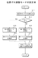
(位置ずれ調整モードの設定例)
図24はカラー画像形成装置300における位置ずれ調整モードの設定例を示すフローチャートである。
この例では中間転写ベルト6で色画像を転写するに当たり、制御装置15では中間転写ベルト6の表面状態の良否を判断し、この中間転写ベルト6の表面状態の良否に応じて当該中間転写ベルト6に色重ね合わせ用のカラーレジストマークCR又は該カラーレジストマークCRを反転した反転カラーレジストマークCRを形成する。この例では制御装置15の判断結果に応じて第1調整モード又は第2調整モードを設定し、その後、第1又は第2のマーク作成方法を選択してマーク検知を行うようにしたものである。
【0214】
カラーレジストマークCRの形成方法としては、非反転カラーレジストマークCRを構成する有効マーク部をトナー像とする第1マーク作成方法と、反転カラーレジストマークCRを構成する有効マーク部以外の領域をトナー像とする第2マーク作成方法とが準備される。もちろん、色重ね合わせ用のカラーレジストマークCRを形成するための印画像情報又は該カラーレジストマークCRを反転した反転カラーレジストマークCRを形成するための反転印画像データDpも予め準備される。
【0215】
これを動作条件にして、図24に示すフローチャートのステップE1でCPU55はRAM57からレジストマーク形成面の表面状態に対応した検知不可フラグFGを読み込む。そして、ステップE2で検知不可フラグがFG=1か否かを判別する。FG=1でない場合、つまり、FG=0でレジストマーク形成面の表面状態が良好である場合はステップE3に移行して第1調整モードを設定し、その後、ステップE6に移行して第1マーク作成方法を選択する。そして、ステップE7に移行する。
【0216】
また、ステップE2で検知不可フラグがFG=1の場合、つまり、レジストマーク形成面に表面状態が予め定めた閾値(基準値)Lthよりも劣る場合は、ステップE5に移行して第2調整モードを設定し、その後、ステップE6に移行して第2マーク作成方法を選択する。そして、ステップE7に移行する。ステップE7では各調整モードに基づいて位置ずれ調整処理がなされる。
【0217】
例えば、上述のステップE3で第1調整モードが設定された場合には、ステップE4で第1マーク作成方法により印画像情報が読み出され、この印画像情報に基づくカラーレジストマークCRが中間転写ベルト6に形成される。位置検出用のレジストセンサ12A,12Bでは中間転写ベルト6に形成されたカラーレジストマークCRの位置が検出される。
【0218】
この中間転写ベルト6に形成されたカラーレジストマークCRの位置検出に基づいて色画像の形成位置を調整するようになされる。制御装置15ではレジストセンサ12A等の出力に基づき、BK色のカラーレジストパターンCRを基準として他のC,M,Y色用の画像形成ユニット10C,10M,10Yが制御される。この制御によって、BK色の書込み位置に合うようにC,M,Y色の書込み位置が調整される。
【0219】
また、ステップE5で第2調整モードが設定された場合には、第2マーク作成方法により反転印画像データDpが読み出され、この反転印画像データDpに基づく反転カラーレジストマークCRが画像形成ユニット10Y,10M,10C,10Kによって中間転写ベルト6に形成される。この中間転写ベルト6に形成された反転カラーレジストマークCRの色抜け部分が成す印画像の位置検出に基づいて色画像の形成位置を調整するようになされる。
【0220】
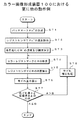
(傷有無検知時の他の例)
図25はカラー画像形成装置300の他の動作例(傷有無検知時)を示すフローチャートである。
この例では図16で説明したレジストセンサ12、記憶装置14及び制御装置15から構成されるマーク検知可否判断手段が備えられ、レジストセンサ12で中間転写ベルト6のレジストマーク形成面の表面状態を検出する際に、非反転カラーレジストマークCRを形成してそのマークエッジ総数と設計値とを比較し、その後、比較結果に基づいて検知不可フラグを設定し、そして、調整モードを見直すようにしたものである。
【0221】
つまり、非反転カラーレジストマークCRに関しては、マーク検知時に、マークエッジの検出回数は予め設計値によって明確になっている。もしも、中間転写ベルト6に誤検知してしまうような傷が有る場合は、マークエッジの検出回数が設計値に一致しなくなる。そのため、色ずれ等の計算結果が不適切となり補正処理が正常にできなくなる。このマークエッジの検出回数を計測することで、これを誤検知するかどうかの判断基準として採用するものである。従って、傷の有無にかかわらず、第1マーク作成方法により非反転カラーレジストマークCRが中間転写ベルト6に形成される。
【0222】
これを前提条件にして、まず、中間転写ベルト6のレジストマーク形成面の表面状態を検出するべく、図25に示すフローチャートのステップF1で非反転カラーレジストマークCRの読み込み処理を実行する。そして、ステップF2に移行してマークエッジ総数と設計値とを比較する。マークエッジ総数と設計値とが一致しない場合は、ステップF3に移行する。ステップF3ではマークエッジ総数が設計値を越えるかが検出される。マークエッジ総数が設計値を越える場合は、レジストマーク形成面の表面状態が経時的な変化によって劣化しているので、ステップF4に移行して検知不可フラグFGがセットされ、FG=1とされる。
【0223】
また、ステップF2でマークエッジ総数と設計値とが一致する場合は、レジストマーク形成面の表面状態が良好なので、ステップF6に移行して検知不可フラグFGがリセットされ、FG=0とされる。検知不可フラグFGはRAM57に一時記憶される。その後の処理は図24に示した位置ずれ調整モードの設定例に従うようになされる。
【0224】
なお、ステップF3でマークエッジ総数が設計値を越えない場合は、ステップF5に移行してマーク読み取り異常処理を実行する。この処理では非反転カラーレジストマークCRの作成不良や、今後の位置ずれ調整モードの設定が不可等を表示装置に表示するようになされる。その後の処理については、図24に示したフローチャートと同じ処理がなされる。
【0225】
このように本発明に係る第1の実施例に係るカラー画像形成装置及びその画像形成方法によれば、レジストセンサ12、記憶装置14及び制御装置15から構成されるマーク検知可否判断手段が備えられ、レジストセンサ12で中間転写ベルト6のレジストマーク形成面の表面状態を検出し、制御装置15では検知不可フラグFGが準備される。カラーレジスト(マークエッジ)検知時にはレジストセンサ12A等で誤検知するかどうかを検知不可フラグFGによって判断するようになされる。
【0226】
従って、中間転写ベルト6を新規に使用する場合や、当該中間転写ベルト6が新品と交換された場合等は、カラーレジストマークCRの位置検出に基づいて色画像の形成位置を調整することができる。メンテナンスや部品消耗等の経時的な変化により中間転写ベルト6に傷等が生じた場合は、反転カラーレジストマークCRにより傷等を覆い隠すことができるので、本来の印画像の位置を正確に検出することができる。
【0227】
これにより、傷等による雑音信号が重畳されない高信頼度の位置検出信号S2に基づいて色画像の形成位置を精度良く調整することができる。また、中間転写ベルト6に正確に色を重ね合わせることができるので、所望の用紙Pに色画像を精度良く転写することができる。
【0228】
[第2の実施例]
図26は本発明に係る第2の実施例としてのカラー画像形成装置300の動作例を示すフローチャートである。
この実施例では中間転写ベルト6に新品検知用のヒューズFが取り付けられ、該ヒューズFを溶断するベルトユニット新品検知回路(New検知手段)90が制御装置15に備えられ、中間転写ベルト6を新規に使用する場合又は当該中間転写ベルト6が新品と交換された場合は、ヒューズFを溶断する。そのヒューズFの溶断有無の判断結果に応じてマーク作成方法を切り換えてレジストマーク検知を行うようになされる。
【0229】
これは中間転写ベルト(ベルトユニット)6が新品の時はヒューズFが導通状態であり、ヒューズFがオープンならばベルトユニットが使用途中であると判断できることによる。これと共に、このベルトユニット新品検知回路90から得られる新品検知信号Sndに基づいて色画像の形成位置を調整する第1調整モードで画像形成処理をするようになされる。
【0230】
これらを動作条件にして、図26に示すフローチャートのステップG1で制御装置15はベルトユニット新品検知回路90から新品検知信号Sndを読み込む。そして、ステップG2で新品検知信号Sndが「L」レベルか否かを判別する。新品検知信号Sndが「L」レベルの場合はベルトユニットが新品なので、ステップG3に移行して第1調整モードを設定し、必要な所定データの設定処理をする。
【0231】
その後、ステップG4に移行してカウンタをクリアし、更に、ステップG5に移行して第1マーク作成方法の選択等を行う。そして、ステップG6に移行してヒューズFの切断処理を行う。この処理ではベルトユニット新品検知回路90に外部設定信号Sopが供給され、トランジスタTRがONし、ヒューズFに過電流を流して溶断することにより、ヒューズFを強制的にオープンさせ、ベルト使用状態になされる。ヒューズFがオープンされた後は、「H」レベルの新品検知信号Sndがベルトユニット新品検知回路90から制御装置15へ出力するようになされる。
【0232】
この例でベルトユニット新品検知回路90から得られる新品検知信号Snd=「H」レベルに基づいて中間転写ベルト6のレジストマーク形成面に非反転カラーレジストマークCRを形成するようにした。ステップG2で新品検知信号Sndが「L」レベルでない場合、つまり、新品検知信号Sndが「H」レベルでベルトユニットが既に使用中の場合は、新品処理をせずに終了する。
【0233】
なお、経時的な変化によって第1の実施例のように第1調整モードから第2調整モードに設定が変更され、第2調整モードに基づいて制御装置15が画像形成ユニット10Y,10M,10C,10Kを制御していた場合であって、ベルトユニットが新品と交換され、ベルトユニット新品検知回路90から得られた新品検知信号Sndが「L」レベル、つまり、「中間転写ベルト6は新品である」を示す場合に第2調整モードから第1調整モードに自動的に処理を切り替えるようになされる。
【0234】
このように本発明に係る第2の実施例に係るカラー画像形成装置及びその画像形成方法によれば、中間転写ベルト6に新品検知用のヒューズFが取り付けられ、該ヒューズFを溶断するベルトユニット新品検知回路90が制御装置15に備えられ、中間転写ベルト6を新規に使用する場合又は当該中間転写ベルト6が新品と交換された場合は、ヒューズFを溶断する。そのヒューズFの溶断有無の判断結果に応じてマーク作成方法を切り換えてレジストマーク検知を行うようになされる。
【0235】
従って、中間転写ベルト6を新規に使用する場合や、当該中間転写ベルト6が新品と交換された場合等は、カラーレジストマークCRの位置検出に基づいて色画像の形成位置を調整することができる。メンテナンスや部品消耗等の経時的な変化により中間転写ベルト6に傷等が生じた場合は、反転カラーレジストマークCRにより傷等を覆い隠すことができるので、本来の印画像の位置を正確に検出することができる。
【0236】
これにより、傷等による雑音信号が重畳されない高信頼度の位置検出信号S2に基づいて色画像の形成位置を精度良く調整することができる。また、中間転写ベルト6に正確に色を重ね合わせることができるので、所望の用紙Pに色画像を精度良く転写することができる。
【0237】
[実施例3]
図27は本発明に係る第3の実施例としてのカラー画像形成装置300の動作例を示すフローチャートである。
この実施例では図16に示した操作手段18を操作して自動又は手動選択を設定し、これに基づいて第1調整モード又は第2調整モードのいずれかを設定する場合を前提とする。
【0238】
これを動作条件にして、図27に示すフローチャートのステップH1で制御装置15では自動又は手動選択の設定によって制御を分岐する。自動又は手動選択はキーオペレーション用の操作画面P1によって設定される。ソフトウエアスイッチSW3の選択ビットAが「0」で自動選択が設定された場合は、ステップH2に移行して検知不可フラグFGが「1」か「0」かが制御装置15によって判断される。検知不可フラグFG=0の場合はステップH4に移行して第1調整モードが設定され、ステップH5に移行して第1マーク作成方法が選択される。その後、ステップH14に移行する。
【0239】
ステップH2で検知不可フラグがFG=1の場合はステップH6に移行して第2調整モードが設定され、ステップH7に移行して第2マーク作成方法が選択される。その後、ステップH14に移行する。
【0240】
また、ステップH1でソフトウエアスイッチSW3の選択ビットAが「1」で手動選択が設定された場合は、ステップH8に移行してソフトウエアスイッチSW3の選択ビットBが読み込まれる。そして、ステップH9に移行して選択ビットBが「1」か「0」かが判別される。選択ビットBが「0」の場合はステップH10に移行して第1調整モードが設定され、ステップH11に移行して第1マーク作成方法が選択される。その後、ステップH14に移行する。
【0241】
ステップH2で選択ビットBが「1」の場合はステップH12に移行して第2調整モードが設定され、ステップH13に移行して第2マーク作成方法が選択される。その後、ステップH14に移行する。ステップH14では第2の実施例と同様にして各調整モードに基づいて位置ずれ調整処理がなされる。
【0242】
例えば、上述のステップH4や,ステップH9で第1調整モードが設定された場合には、ステップH5やH11で第1マーク作成方法により印画像情報が読み出され、この印画像情報に基づくカラーレジストマークCRが中間転写ベルト6に形成される。位置検出用のレジストセンサ12A,12B又は、12A〜12Cでは中間転写ベルト6に形成されたカラーレジストマークCRの位置が検出される。この中間転写ベルト6に形成されたカラーレジストマークCRの位置検出に基づいて色画像の形成位置を調整するようになされる。制御装置15ではレジストセンサ12A等の出力に基づき、BK色のカラーレジストパターンCRを基準として他のC,M,Y色用の画像形成ユニット10C,10M,10Yが制御される。この制御によって、BK色の書込み位置に合うようにC,M,Y色の書込み位置が調整される。
【0243】
また、ステップH6やH12で第2調整モードが設定された場合には、第2マーク作成方法により反転印画像データDpが読み出され、この反転印画像データDpに基づく反転カラーレジストマークCRが画像形成ユニット10Y,10M,10C,10Kによって中間転写ベルト6に形成される。この中間転写ベルト6に形成された反転カラーレジストマークCRの色抜け部分が成す印画像の位置検出に基づいて色画像の形成位置を調整するようになされる。
【0244】
このように本発明に係る第3の実施例に係るカラー画像形成装置及びその画像形成方法によれば、操作手段18を操作して自動又は手動選択を設定し、これに基づいて第1調整モード又は第2調整モードのいずれかを設定するようになされる。
【0245】
従って、中間転写ベルト6を新規に使用する場合や、当該中間転写ベルト6が新品と交換された場合等は、カラーレジストマークCRの位置検出に基づいて色画像の形成位置を調整することができる。メンテナンスや部品消耗等の経時的な変化により中間転写ベルト6に傷等が生じた場合は、反転カラーレジストマークCRにより傷等を覆い隠すことができるので、本来の印画像の位置を正確に検出することができる。
【0246】
これにより、傷等による雑音信号が重畳されない高信頼度の位置検出信号S2に基づいて色画像の形成位置を精度良く調整することができる。しかも、レジストマークの形成に係るトナー量を抑制することができる。また、中間転写ベルト6に正確に色を重ね合わせることができるので、所望の用紙Pに色画像を精度良く転写することができる。
【0247】
(4)第4の実施形態
図28は、本発明の第4の実施形態としてのカラー画像形成装置400の構成例を示す概念図である。
この実施形態では第1〜第3の画像形成装置で説明したような中間転写ベルト6が省略されており、その代わりに4色の画像形成系で共用する感光体ベルト60が備えられ、この感光体ベルト60上でカラー画像を形成するようにしたものである。
【0248】
もちろん、本実施形態でも、色画像の濃度検出系や位置検出系の出力に基づいて画像形成ユニット10Y’、10M’、10C’、10K’を制御する制御装置15を備えている。この制御装置15では色画像の位置検出系で色濃度補正用の切片画像の濃度を検出し、当該位置検出系から出力される切片画像の濃度検出信号に基づいて印画像の位置検出用の制御基準値を校正する。
【0249】
そして、感光体ベルト60における反射光量の変動や、センサ発光量の低減等により当該感光体ベルト60の使用環境が経時的に変化した場合であっても、本来の印画像の位置を正確に検出できるようにすると共に、高信頼度の位置検出信号に基づいて色画像の形成位置を精度良く調整できるようにしたものである。
【0250】
図28に示すカラー画像形成装置400は画像形成装置の他の一例を構成するものであり、任意の画像情報に基づいて感光体ベルト60上で色を重ね合わせ、所定の用紙Pに色画像を形成する装置である。
【0251】
図28において、カラー画像形成装置400は、画像形成装置本体101’と画像読取装置102とから構成される。画像形成装置本体101’の上部には、自動原稿給紙装置201と原稿画像走査露光装置202から成る画像読取装置102が設置されている。自動原稿給紙装置201の原稿台上に載置された原稿dは搬送手段により搬送され、原稿画像走査露光装置202の光学系により原稿の片面又は両面の画像が走査露光され、ラインイメージセンサCCDに読み込まれる。
【0252】
ラインイメージセンサCCDにより光電変換されたアナログ信号は、図示しない画像処理部において、アナログ処理、A/D変換、シェーディング補正及び画像圧縮処理等がなされ、画像情報となる。その後、画像情報は画像形成手段の一例を構成する画像書き込み部(露光手段)3Y、3M、3C、3Kへ送られる。
【0253】
自動原稿給紙装置201は第1〜第3の画像形成装置と同様にして自動両面原稿搬送手段を備えている。この自動原稿給紙装置201は原稿載置台上から給送される多数枚の原稿dの内容を連続して一挙に読み取り、原稿内容を記憶手段に蓄積するようになされる(電子RDH機能)。この電子RDH機能は、複写機能により多数枚の原稿内容を複写する場合、或いはファクシミリ機能により多数枚の原稿dを送信する場合等に便利に使用される。
【0254】
画像形成装置本体101’は、タンデム型カラー画像形成装置と称せられるもので、複数組の画像形成ユニット(画像形成系)10Y’、10M’、10C’、10K’と、像形成体の一例となる無終端状の感光体ベルト60と、再給紙機構(ADU機構)を含む給紙搬送手段と、トナー像を定着するための定着装置17からなる。
【0255】
イエロー(Y)色の画像を形成する画像形成ユニット10Y’は第1〜第3の画像形成装置に比べて感光体ドラムや像形成体用のクリーニング手段8Y等がユニット外に追いやられ、像形成体としての感光体ベルト60を4色の画像形成系で共用するようになされる。この感光体ベルト60の所定の位置に対峙して配置されたY色用の帯電手段2Y、露光手段3Y及び現像装置4Yを有する。マゼンタ(M)色の画像を形成する画像形成ユニット10M’は、M色用の帯電手段2M、露光手段3M及び現像装置4Mを有する。
【0256】
シアン(C)色の画像を形成する画像形成ユニット10C’はC色用の帯電手段2C、露光手段3C及び現像装置4Cを有する。黒(BK)色の画像を形成する画像形成ユニット10K’はBK色用の帯電手段2K、露光手段3K及び現像装置4Kを有する。
【0257】
帯電手段2Yと露光手段3Y、帯電手段2Mと露光手段3M、帯電手段2Cと露光手段3C及び帯電手段2Kと露光手段3Kとは、潜像形成手段を構成する。現像装置4Y、4M、4C、4Kによる現像は、使用するトナー極性と同極性(本実施形態においては負極性)の直流電圧に交流電圧を重畳した現像バイアスが印加される反転現像にて行われる。感光体ベルト60は、複数のローラにより巻回され、回動可能に支持されている。
【0258】
画像形成プロセスの概要について以下に説明する。画像形成ユニット10Y’、10M’、10C’及び10K’より、感光体ベルト60上に各色の静電潜像が形成されると共に、この静電潜像が各色のトナーによって現像される。感光体ベルト60上には、使用するトナーと反対極性(本実施形態においては正極性)のバイアス(不図示)が印加される。トナー像を合成されたカラー画像(色画像:カラートナー像)が感光体ベルト60上で形成される。その後、カラー画像は感光体ベルト60から用紙Pへ転写される。
【0259】
なお、給紙カセット20A、20B、20C内に収容された用紙Pは、第1〜第3の実施形態と同様にして給紙カセット20A、20B、20Cにそれぞれ設けられる送り出しローラ21および給紙ローラ22Aにより給紙され、搬送ローラ22B、22C、22D、レジストローラ23等を経て、転写ローラ7Aに搬送され、用紙P上の一方の面(表面)にカラー画像が一括して転写される。
【0260】
カラー画像が転写された用紙Pは、定着装置17により定着処理され、排紙ローラ24に挟持されて機外の排紙トレイ25上に載置される。転写後の感光体ベルト60の周面上に残った転写残トナーは、像形成体クリーニング手段8Aによりクリーニングされ次の画像形成サイクルに入る。なお、両面画像形成処理や用紙Pについては図1で説明したのでその説明を省略する。
【0261】
上述のクリーニング手段8Aの上流側であって、感光体ベルト60の左側には、第1の検出手段の一例となるトナー像濃度検知用のセンサ(以下、単にトナー濃度センサ11という)が設けられており、感光体ベルト60に形成されたトナー像(色画像)の濃度を検出し、濃度検出信号S1を発生するようになされる。もちろん、この位置に限られることはなく、図28で波線に示した位置、転写ローラ7Aとレジストローラ23との間に、トナー濃度センサ11やレジストセンサ12を備えてもよい。
【0262】
このトナー濃度センサ11に並べて第2の検出手段の一例となるトナー像位置ずれ検知用のセンサ(以下、単にレジストセンサ12という)が設けられており、感光体ベルト60に形成された印画像(以下でカラーレジストマークCRという)の位置を検出し、位置検出信号S2を発生するようになされる。画像形成装置本体101’には制御装置15が設けられ、濃度検出信号S1及び位置検出信号S2に基づいてカラーレジストマーク検知処理をするようになされる。
【0263】
ここでのカラーレジストマーク検知処理では、色重ね合わせ用のカラーレジストマークCRを感光体ベルト60に形成し、この感光体ベルト60に形成されたカラーレジストマークCRの位置(エッジ、重心等)をレジストセンサ12によって検出するようになされる。この処理はカラーレジストマークCRの位置に基づいて色画像の形成位置を調整するためである。この例でも、第1〜第3の実施形態と同様にして、感光体ベルト60の使用環境が経時的に変化した場合であっても、本来のカラーレジストマークCRの位置を正確に検出できるようにすると共に、高信頼度の位置検出信号S2に基づいて色画像の形成位置を精度良く調整できるようになされる。
【0264】
図29は本発明に係る第4の実施形態としてのカラー画像形成装置400の画像転写及び画像形成系の構成例を示すブロック図である。図29に示すカラー画像形成装置400は図28に示した感光体ベルト60を画像転写系Iとし、画像形成ユニット10Y’,10M’,10C’,10K’を画像形成系IIとして抜き出したものである。図29において、カラー画像形成装置400は制御装置15を有している。制御装置15にはトナー濃度センサ11が接続されており、感光体ベルト60に形成されたトナー像(色画像)の濃度を検出し、濃度検出信号S1を制御装置15へ出力するようになされる。
【0265】
制御装置15にはトナー濃度センサ11の他にレジストセンサ12が接続されており、感光体ベルト60に形成されたトナー像(色画像)の位置を検出して位置検出信号S2を制御装置15へ出力するようになされる。制御装置15はトナー濃度センサ11から得られる濃度検出信号S1及びレジストセンサ12から得られる位置検出信号S2に基づいて画像形成ユニット10Y’,10M’,10C’,10K’を制御するようになされる。
【0266】
この例で制御装置15は、画像形成ユニット10Y’,10M’,10C’における補正手段5Y,5M,5Cを通じて、主/副走査時の書き出し位置調整及び画像書込み部3Y,3M,3Cにおける位置調整(スキュー調整)、主走査書込みクロック信号の補正(横倍調整/部分横倍調整)等がなされる(図3参照)。
【0267】
制御内容によっては画像形成ユニット10K’を基準にして画像形成ユニット10Y’,10M’,10C’のいずれか一方又は3つを制御するようにしてもよい。制御装置15の負担を軽減できる。もちろん、感光体ベルト60を制御対象に入れてもよい。その場合には、図示しない蛇行補正機構を設け、感光体ベルト60の蛇行を補正して色ずれを調整するようにしてもよい。
【0268】
制御装置15には画像形成ユニット10Y’,10M’,10C’,10K’が接続されており、画像形成ユニット10Y’では、任意の画像情報Dinを構成するY色用の画像情報Dy、主走査方向のY色書込み周期用のH−VALID信号(以下Y−HV信号という)、副走査方向のY色書込み周期用のH−VALID信号(以下Y−VV信号という)、Y色用のポリゴン駆動クロック信号(以下でYポリゴンCLKという)を入力し、画像情報Dy、Y−HV信号、Y−VV信号、YポリゴンCLKに基づいて感光体ベルト60にY色のトナー画像を形成する。
【0269】
画像形成ユニット10M’ではM色用の画像情報Dm、主走査方向のM色書込み周期用のH−VALID信号(以下M−HV信号という)、副走査方向のM色書込み周期用のH−VALID信号(以下M−VV信号という)、M色用のポリゴン駆動クロック信号(以下でMポリゴンCLKという)を入力し、画像情報Dm、M−HV信号、M−VV信号、MポリゴンCLKに基づいて感光体ベルト60にM色のトナー画像を形成する。
【0270】
画像形成ユニット10C’ではC色用の画像情報Dc、主走査方向のC色書込み周期用のH−VALID信号(以下C−HV信号という)、副走査方向のC色書込み周期用のH−VALID信号(以下C−VV信号という)、C色用のポリゴン駆動クロック信号(以下でCポリゴンCLKという)を入力し、画像情報Dc、C−HV信号、C−VV信号、CポリゴンCLKに基づいて感光体ベルト60にC色のトナー画像を形成する。
【0271】
画像形成ユニット10K’ではBK色用の画像情報Dk、主走査方向のBK色書込み周期用のH−VALID信号(以下K−HV信号という)、副走査方向のBK色書込み周期用のH−VALID信号(以下K−VV信号という)、BK色用のポリゴン駆動クロック信号(以下でKポリゴンCLKという)を入力し、画像情報Dk、K−HV信号、K−VV信号、KポリゴンCLKに基づいて感光体ベルト60にBK色のトナー画像を形成するようになされる。
【0272】
この例ではY色用の画像書き込み部(露光手段)3Yには補正手段5Yが取り付けられており、制御装置15からのY色用の位置補正信号Syに基づいてY色画像の形成位置を調整するようになされる。同様にしてM色用の画像書き込み部3Mには補正手段5Mが取り付けられており、制御装置15からのM色用の位置補正信号Smに基づいてM色画像の形成位置を調整するようになされる。C色用の画像書き込み部3Cには補正手段5Cが取り付けられており、制御装置15からのC色用の位置補正信号Scに基づいてY色画像の形成位置を調整するようになされる。
【0273】
BK色用の画像書き込み部3Kには補正手段5Kが取り付けられており、制御装置15からのBK色用の位置補正信号Skに基づいてBK色画像の形成位置を調整するようになされる。この例で色ずれ量の算出に関しては、BK色のカラーレジストマークCRを基準にしている。Y,M,C色の色画像の書込み位置をBK色に合わせるように調整するためである。
【0274】
このY色の書込み位置調整に関しては、第1の実施形態で説明したように、BK色のカラーレジストマークCRの書込み位置と、Y色のカラーレジストマークCRの書込み位置とを検知し、Y色のカラーレジストマークCRの書込み位置をBK色のカラーレジストマークCRの書込み位置に換算した際のずれ量からその補正量を算出する。同様にして、M、C色の書込み位置調整に関しても、BK色のカラーレジストマークCRの書込み位置と、MやC色のカラーレジストマークCRの書込み位置とのずれ量を各々検知し、このずれ量から各々の補正量を算出する。その後、BK色用の画像形成ユニット10K’以外のY、M、C色用の画像ユニット10Y’,10M’,10C’を調整するようになされる。
【0275】
このため、BK画像ユニットでは感光体ベルト60に対してBK色のみの出力で正規の主/副走査時の書き込み位置調整及び画像書込み部3Kにおける横倍調整、部分横倍調整及び傾き調整等がなされる。BK色について調整し基準とするためである。その後、本発明方式のカラーレジスト調整に移行してBK色に合わせてY,M,C色の書込み位置を合わせるレジスト調整を実行するようになされる。
【0276】
また、制御装置15では切片画像の一例となる色濃度補正用のパッチマークを感光体ベルト60に形成するように画像形成ユニット10Y’,10M’,10C’が制御される。感光体ベルト60に形成されたパッチマークの濃度はレジストセンサ12によって検出される。その後、パッチマークの濃度に基づいて色重ね合わせ用のカラーレジストマークCRの濃度が調整され、ここで濃度調整されたカラーレジストマークCRを感光体ベルト60に形成するように制御装置15によって画像形成ユニット10Y’,10M’,10C’,10K’が制御される。
【0277】
感光体ベルト60に形成されたカラーレジストマークCRの位置はレジストセンサ12によって検出される。制御装置15ではレジストセンサ12から出力されるパッチマークの濃度情報を含む位置検出信号S2’に基づいてカラーレジストマークCRの位置検出時の閾値Lthをリアルタイムに校正できるようになる。このカラーレジストマークCRの位置に基づいて色画像の形成位置を調整するように画像形成ユニット10Y’,10M’,10C’,10K’を制御するようになされる。
【0278】
この例では、レジストセンサ12から出力されるパッチマークの非形成部分に係る濃度情報を含む位置検出信号S2’の最大値(MAX)及び当該パッチマークの形成部分に係る最小値(MIN)を検出し、この位置検出信号S2’の最小値及び最大値に基づいて平均値を演算する。
【0279】
この演算は、すなわち、パッチマークの無いベースの反射出力の値と、パッチマーク部の反射出力の値が最も近い値が2値化する閾値を決める最悪の関係となるため、その条件となる値を使用して平均値(中央値)を割り出し、2値化の閾値を決定するためである。この例では、当該平均値をレジストセンサ12の制御基準値とし、この制御基準値に基づいてカラーレジストマークCRの通過タイミングを検出するようになされる。レジストセンサ12の制御基準値は平均値近傍であってもよい。
【0280】
もちろん、これに限られることはなく、同一シーケンス内で制御装置15により、色濃度補正用のパッチマークを感光体ベルト60に形成し、感光体ベルト60に形成されたパッチマークの濃度をトナー濃度センサ11によって検出し、色画像の濃度を調整する色補正処理を実行すると共に、感光体ベルト60に形成されたパッチマークの濃度をレジストセンサ12により連続して検出してもよい。パッチ検出時に生成されるパッチマークをレジストセンサ12で連続して検出することで、最も信号レベルが確保できるカラーレジストマークCRの濃度を決めることができる。
【0281】
その後は、パッチマークの濃度に基づいて色重ね合わせ用のカラーレジストマークCRの濃度を調整し、濃度調整されたカラーレジストマークCRを感光体ベルト60に形成し、感光体ベルト60に形成されたカラーレジストマークCRの位置をレジストセンサ12によって検出し、カラーレジストマークCRの位置に基づいて色画像の形成位置を調整する色重ね合わせ処理をするようになされる。なお、制御装置15の位置ずれ制御系に係る内部構成例については図3を参照されたい。
【0282】
図30はY色用の画像書込み部3Y及びその補正手段5Yの構成例を示すイメージ図である。図30に示すY色用の画像書込み部3Yは半導体レーザ光源31、光学系32,33、ポリゴンミラー34、ポリゴンモータ35及びf(θ)レンズを有している。半導体レーザ光源31ではY色用の画像情報Dyに基づいてレーザ光が発生される。半導体レーザ光源31から出射されたレーザ光は光学系によって所定のビーム光に整形される。
【0283】
このビーム光はポリゴンミラー34によって副走査方向に偏向される。ポリゴンミラー34は制御装置15からのYポリゴンCLKに基づき、ポリゴンモータ35によって回転される。ポリゴンミラー34によって偏向されるビーム光はf(θ)レンズ36によって感光体ベルト60の方へ結像される。この動作により、感光体ベルト60にレジストマークCR等の静電潜像を形成するようになされる。
【0284】
この画像書込み部3Yには補正手段5Yが設けられる。補正手段5Yはレンズ保持機構41及び、f(θ)調整機構42等を有している。この例で色ずれ量の算出に関しては、BK色のレジストマークCRを基準にしている。Y,M,C色の色画像の書込み位置をBK色に合わせるように調整するためである。補正処理内容は例えば、次のi〜vの5つある。補正内容のうち、i〜iiiは画像データを補正することにより実現され、iv及びvはモータを駆動し、実際に、書込み部3Y,3M,3C,3Kを駆動して調整するようになされる。
【0285】
i.主走査補正処理
この処理は、Y,M,C、BK色の色画像の主走査方向の書出し位置を揃える補正である。例えば、Y色の書込み位置補正に関しては、BK色のレジストマークCRの主走査書込みタイミングと、Y色のレジストマークCRの主走査書込みタイミングとを検知し、Y色のレジストマークCRの書込みタイミングをBK色のレジストマークCRの書込み位置に換算した際のずれ量からその補正量を算出する。この補正量に基づいて、主走査方向のBK色のレジストマークCRの書込み位置と、Y,M,C色の色画像の書込み位置とが機械の画像形成位置に合わせられる。
【0286】
ii.副走査補正処理
この処理は、Y,M,C、BK色の色画像の副走査方向における書出し位置を揃える補正である。例えば、Y色の書込み位置調整に関しては、BK色のレジストマークCRの副走査書込みタイミングと、Y色のレジストマークCRの副走査書込みタイミングとを検知し、Y色のレジストマークCRの書込みタイミングをBK色のレジストマークCRの書込み位置に換算した際のずれ量からその補正量を算出する。この補正量に基づいて、この補正量に基づいて、副走査方向のBK色のレジストマークCRの書込み位置と、Y,M,C色の色画像の書込み位置とが機械の画像形成位置に合わせられる。
【0287】
iii.全体横倍補正処理
この処理は、Y,M,C,BK色の色画像の全体における画像形成位置を揃える補正である。例えば、画像クロック信号の周期を調整して、レーザ発光タイミングを調整し、この調整に基づいて全体横倍ずれ量を補正するようになされる。
【0288】
iv.部分横倍補正処理
この処理は、各書込み部3Y,3M,3C等の水平位置(方向)の傾きを調整する補正である。例えば、図3に示した書込み部3Yのレンズ保持機構41にはf(θ)レンズ36が取り付けられている。レンズ保持機構41はf(θ)調整機構42に対して可動自在に取り付けられる。f(θ)調整機構42では制御装置15から出力された、回転成分を含む位置補正信号Syに基づいてレンズ保持機構41をX−Y(水平)方向に移動調整するようになされる。このf(θ)調整機構42にはアクチュエータ(圧電素子)やモータ制御等により具現化される。感光体ベルト60に対する書込み部3Yの水平位置の傾きを調整するためである。他の画像形成ユニット10M,10Cにおいても同様な処理がなされる。
【0289】
v.スキュー補正処理
この処理は、各画像書込み部3Y,3M,3C等の垂直位置の傾きを調整する補正である。例えば、図3に示したモータ9Yでは位置補正信号S13(Y)に基づいて画像書込み部3Yの姿勢を調整するようになされる。感光体ベルト60に対する画像書込み部3Yの垂直位置の傾きを調整するためである。他の画像形成ユニット10M,10Cにおいても同様な処理がなされる。
【0290】
この例ではカラーレジストマークCRの位置検出用の制御基準値を校正するために、予め画像形成ユニット10Y’,10M’,10C’,10K’を介して感光体ベルト60にパッチマークが形成される。制御基準値は感光体ベルト60に形成されたカラーレジストの通過タイミングを検出する際の二値化しき値レベルである。
【0291】
図31はトナー濃度センサ11及びレジストセンサ12A,12Bの配置例を示す斜視図である。図31において、レジストセンサ12A,12Bは感光体ベルト60の両端の上部に設けられる。レジストセンサ12Aの上流側にはトナー濃度センサ11が取り付けられる。
【0292】
トナー濃度センサ11及びレジストセンサ12A,12Bは図31に示した位置に限られることはなく、図28で波線に示した転写ローラ7Aとレジストローラ23との間に取り付けてもよい。ここに取り付けた場合は、画像形成位置とカラーレジストマークCRの検知位置が近いので、像形成体クリーニング手段8Aに近接した上流側に設ける場合に比べて、いち早く位置ずれを検出することができ、画像処理の高速化に寄与するところが大きい。
【0293】
この例では、トナー濃度センサ11及びレジストセンサ12は、感光体ベルト60の走行方向の所定位置に連続して(並べて)取り付けられる。感光体ベルト60が一周する間に濃度検出信号S1に基づいてレジストセンサ12を校正するためである。つまり、制御装置15では、予め色濃度補正用のパッチマークPmを形成するように例えば、画像形成ユニット10K’を制御して濃度の異なるパッチ(1)出力〜パッチ(4)出力を感光体ベルト60に形成する。
【0294】
そして、感光体ベルト60が一周する間に形成されたパッチマークPmの濃度がトナー濃度センサ11によって検出され、色画像の濃度を調整する色補正制御を実行すると共に、感光体ベルト60に形成されたパッチマークPmの濃度がレジストセンサ12A等により連続して検出される。その後、パッチマークPmの濃度に基づいて色重ね合わせ用のカラーレジストの濃度が調整される。
【0295】
なお、レジストセンサ12A等によるパッチマークPmの濃度検知例については、図6を参照され、レジストセンサ12A等による濃度情報を含む位置検出信号S2’の波形例については、図7A及びBを各々参照されたい。また、レジストセンサ12A等によるパッチマークPmの濃度検知に基づく閾値設定例については、図8を参照されたい。
【0296】
図32はレジストセンサ12A,12BによるカラーレジストマークCRの検知例を示す斜視図である。図32において、パッチマーク検出後、感光体ベルト60が次に一周する間に濃度調整された例えば、「フ」字状のカラーレジストマークCRを形成するように画像形成ユニット10Y’,10M’,10C’,10K’が制御される。
【0297】
この感光体ベルト60に形成されたカラーレジストマークCRの位置はレジストセンサ12A,12Bによって検出される。そして、制御装置15ではカラーレジストマークCRの位置に基づいて色画像の形成位置を調整する色重ね合わせ制御を実行するようになる。なお、レジストセンサ12A等による位置検出信号S2の二値化例については図10A及びBを参照されたい。
【0298】
続いて、第1の画像形成方法に係るカラー画像形成装置400の動作例について説明をする。図33はカラー画像形成装置400の動作例を示すフローチャートである。
【0299】
この実施例では画像転写系Iに感光体ベルト60が設けられる場合であって、任意の画像情報に基づいて感光体ベルト60上で色を重ね合わせ、用紙Pに色画像を形成する前に、カラーレジストマークCRの位置に基づいて色画像の形成位置を調整する場合を前提とする。更に、色画像の形成位置を調整する前に、カラーレジストマークCRの位置検出時の閾値Lthをリアルタイムに校正する場合を例に挙げる。トナー濃度センサ11(第1の検出系)及びレジストセンサ12A,12B(第2の検出系)は感光体ベルト60の走行方向(ベルト進行方向)に同位相となる位置に連続して取り付けられている。
【0300】
これを画像形成条件にして、図33のフローチャートのステップJ1〜J3でレジストセンサ12A,12B等の初期調整を行い、その後、ステップJ4〜J8で書込み位置調整をするようになされる。この初期調整では下地のセンサ出力との濃度検出用のマークのセンサ出力から最適な閾値Lthが決定される。
【0301】
この例では、ステップJ1で感光体ベルト60に色濃度補正用のパッチマークPmを形成する。このとき、画像形成ユニット10Y’,10M’,10C’又は10K’では図31に示したように濃度の異なる何種類かのパッチマークPmが感光体ベルト60に形成される。その後、ステップJ2に移行して感光体ベルト60に形成されたパッチマークPmの濃度をレジストセンサ12A等で検出する。例えば、レジストセンサ12Aで検出された濃度情報を含む位置検出信号S2’は図6に示すようになる。
【0302】
更に、ステップJ3に移行してレジストセンサ12Aから出力されるパッチマークPmの濃度情報を含む位置検出信号S2’に基づいてカラーレジストマークCRの位置検出時の閾値Lthを校正する。閾値Lthは図8に示した演算で校正する。このとき、制御装置15ではレジストセンサ12A等から出力されるパッチマークPmの形成部分の濃度情報を含む位置検出信号S2’の最大値(MAX)及びその非形成部分の最小値(MIN)が検出され、濃度情報を含む位置検出信号S2’の最大値及び最小値に基づいて平均値が演算される。パッチマークPmの非形成部分の濃度情報を含む位置検出信号S2’は感光体ベルト60の下地を反映するものである。
【0303】
この平均値がレジストセンサ12の閾値Lthとなされる。また、パッチマークPmの濃度に基づいて色重ね合わせ用のカラーレジストマークCRの濃度も調整するようになされる。ここで検出されたパッチマークPmの濃度によりカラーレジストマークCRを形成することで、カラーレジストマークCRの濃度をレジストセンサ12の検出に最も適切にできる。また、カラーレジストマーク形成時のトナー消費量と調整時間を削減できる。
【0304】
そして、濃度調整されたカラーレジストマークCR(印画像)をステップJ4で感光体ベルト60に形成する。その後、感光体ベルト60に形成されたカラーレジストマークCRの位置をステップJ5でレジストセンサ12によって検出される。このとき、図33Aに示した閾値Lthに基づいてカラーレジストマークCRの通過タイミングが検出される。その後、ステップJ6で通過タイミングに基づいて色ずれ量を算出する。カラーレジストマークCRの位置に基づいて色画像の形成位置を調整するためである。
【0305】
そして、ステップJ7に移行してBK色のレジストマークCRを基準にしてY色のレジストマークCRを比較する。色ずれ量が目標値以下の場合は色画像の形成位置を調整することなく処理を終了する。色ずれ量が目標値を越える場合はステップJ8に移行して色ずれ補正をする。この色ずれ補正では、Y色のレジストマークCRの書込み位置をBK色に合わせるように調整され、Y色用の補正手段5Yにおいて、主走査補正処理、副走査補正処理、全体横倍補正処理、部分横倍補正処理及び、スキュー補正処理がなされる。これにより、感光体ベルト60へのY色用の画像形成位置を調整することができる。
【0306】
そして、ステップJ4に戻って上述した処理を繰り返す。例えば、M色用の補正手段5Mにおいて、BK色のレジストマークCRを基準にして、M色の色画像の書込み位置をBK色に合わせるように調整される。この補正では、主走査補正処理、副走査補正処理、全体横倍補正処理、部分横倍補正処理及び、スキュー補正処理がなされる。これにより、感光体ベルト60へのM色用の画像形成位置を調整することができる。同様にして、C色についても、色ずれ補正処理がなされる。色ずれ量を零にすることで、色画像の形成位置を最適に調整するためである。その後は、従来方式と同様にして画像形成位置が最適に調整された画像形成ユニット10Y’,10M’,10C’,10K’によって色画像が感光体ベルト60に形成される。
【0307】
このように、本発明に係る第4の実施形態としてのカラー画像形成装置400及び画像形成方法によれば、レジストセンサ12で色濃度補正用のパッチマークPmの濃度を検出し、当該レジストセンサ12から出力されるパッチマークPmの濃度情報を含む位置検出信号S2’に基づいて制御装置15でカラーレジストマークCRの位置検出用の閾値Lthを校正するようになされる。
【0308】
従って、カラーレジストマークCRの位置検出用の閾値Lthを使用環境に応じて画像形成ユニット10Y’,10M’,10C’,10K’の使用状態に合わせ込むような補正することができる。しかも、カラーレジストマークの濃度を最適化できるので、カラーレジストマーク検知処理の高い精度を確保することができる。
【0309】
これにより、感光体ベルト60における反射光量の変動や、センサ発光量の低減等により使用環境が経時的に変化した場合であっても、本来のカラーレジストマークCRの位置を正確に検出できるので、高信頼度の位置検出信号S2に基づいて色画像の形成位置を精度良く調整することができる。従って、感光体ベルト60で正確に色を重ね合わせることができるので、所望の用紙Pに色画像を精度良く転写することができる。
【0310】
(5)第5の実施形態
図34は本発明に係る第5の実施形態としてのカラー画像形成装置500の画像転写及び画像形成系の構成例を示すブロック図である。
この実施形態では任意の画像情報に基づいて色を重ね合わせ色画像を形成する場合に、感光体ベルト60に色重ね合わせ用の印画像を反転した反転印画像を形成するように画像形成ユニット10Y’,10M’,10C’,10K’を制御する制御装置15を備え、少なくとも、予め反転印画像を感光体ベルト60に形成し、その後、この反転印画像の色抜け部分が成す印画像の位置検出に基づいて色画像の形成位置を調整し、メンテナンスや部品消耗等の経時的な変化により感光体ベルト60に傷等が生じた場合であっても、所望の用紙Pに色画像を精度良く転写できるようにしたものである。
【0311】
図34に示すカラー画像形成装置500は任意の画像情報に基づいて色を重ね合わせ色画像を形成する装置である。当該装置500は感光体ベルト60を有しており、この感光体ベルト60上でカラー画像を形成した後に、このカラー画像を所望の用紙Pに転写するようになされる。この感光体ベルト60に沿って画像形成ユニット10Y’,10M’,10C’,10K’が設けられ、色画像を形成するようになされる。感光体ベルト60の例えば、左側には検出手段の一例となるレジストセンサ12が取り付けられ、感光体ベルト60に形成された色画像の位置を検出するようになされる。
【0312】
レジストセンサ12には制御装置15が接続されており、このレジストセンサ12の出力に基づいて感光体ベルト60及び画像形成ユニット10Y’,10M’,10C’,10K’を制御するようになされる。制御装置15では少なくとも、予め色重ね合わせ用の印画像を反転した反転カラーレジストマークCRを感光体ベルト60に形成し、この感光体ベルト60に形成された反転カラーレジストマークCRの色抜け部分が成す印画像の位置検出に基づいて色画像の形成位置を調整するように画像形成ユニット10Y’,10M’,10C’,10K’を制御する。例えば、制御装置15ではレジストセンサ12A等の出力に基づき、BK色のカラーレジストパターンCRを基準として他のC,M,Y色用の画像形成ユニット10C’,10M’,10Y’が制御される。この制御によって、BK色の書込み位置に合うようにC,M,Y色の書込み位置が調整される。
【0313】
制御装置15には記憶装置14が接続されており、色重ね合わせ用の印画像を反転するための複数種類の反転印画像データDpが格納される。もちろん、これに限られることはなく、色重ね合わせ用の印画像を形成するための印画像情報を記憶装置14に格納しておき、カラーレジストマーク検知時に、印画像情報及びパターン幅に基づいて反転印画像データDpを作成するようにしてもよい。反転印画像データDpに基づいて印画像を反転した反転カラーレジストマークCRを感光体ベルト60に形成するためである。
【0314】
この例で感光体ベルト60にY色用のトナー像を形成する現像装置4Yが画像形成ユニット10Y’に備えられ、M色用のトナー像を形成する現像装置4Mが画像形成ユニット10M’に備えられ、C色用のトナー像を形成する現像装置4Cが画像形成ユニット10C’に備えられ、BK色用のトナー像を形成する現像装置4Kが画像形成ユニット10K’に備えられ、これらの現像装置4Y,4M,4C,4Kによって感光体ベルト60に形成されたY色、M色、C色及びBK色のトナー像部分が各々反転カラーレジストマークCR’を構成し、トナー像を形成しない色抜け部分が印画像を構成するようになる。
【0315】
なお、第4の実施形態と同じ名称及び同じ符号のものは同じ機能を有するためその説明を省略する。また、非反転カラーレジストマークCR及び反転カラーレジストマークCR’の構成例については図13A及びBを参照されたい。
【0316】
図35はBK,C,M,Y色用の反転カラーレジストマークCRの形成例を示すイメージ図である。
図35に示すBK色用の反転カラーレジストマークCR(以下で単にBK色反転パターンPKという)、C色用の反転カラーレジストマークCR(以下で単にC色反転パターンPCという)、M色用の反転カラーレジストマークCR(以下で単にM色反転パターンPMという)、Y色用の反転カラーレジストマークCR(以下で単にY色反転パターンPYという)は感光体ベルト60の主走査方向に並べて形成したパターン例である。
【0317】
各色反転パターンPK,PC,PM,PYは2つのレジストセンサ12A,12Bによって検出される場合を示している。レジストセンサ12Aは走行方向に向かって感光体ベルト60上の右側に設けられ、レジストセンサ12Bは感光体ベルト60上の左側に設けられる。波線は感光体ベルト60が回転することによる各々のレジストセンサ12A,12Bの見かけ上の軌跡である。
【0318】
このパターン例ではBK色反転パターンPKが副走査方向で連続し、全面一様なトナー像の上にマーク部を色抜けとして形成されており、レジストセンサ12A及び12Bによって検出される。このように、BK色反転パターンPK等を副走査方向で連続して全面一様に形成すると、トナーの消費量が多くなる。そこで、C色用や、M色用あるいはY色用の反転パターンPC,PM,PYのようにパターン幅Wsを制限し、マーク部分だけに一様なトナー像を形成するとよい。トナーの消費量を少なく抑えることができる。
【0319】
M色用の反転パターンPMの例では印画像の幅よりも、その反転パターンPMのパターン幅Wsを小さくした場合である。この場合はトナーの消費量を最小限に抑えることができる。反転パターンPMは色抜け部分を仕切る複数の部分図形パターンを並べたような構成となり、色抜け部分により形成される印画像の全体を取り囲む矩形状のパターン構成のBK、C、Y色の各々の反転パターンPK,PC,PYと異なっている。
【0320】
これらの複数種類の反転パターンPY、PM、PC,PKを形成するための反転印画像データDpは記憶装置14に格納するようになされる。制御装置15で感光体ベルト60の使用状態に応じて反転パターンPY、PM、PC,PKを選択するようにするとよい。
【0321】
また、感光体ベルト60の主走査方向に二以上の反転カラーレジストを並べて形成する場合に、制御装置15によって感光体ベルト60に形成される一方の反転カラーレジストの下部と、他方の反転カラーレジストの上部とを重なるように、例えば、1画素が重なるように画像形成ユニット10Y’,10M’,10C’,10K’を制御する。
【0322】
これにより、図35に示すM色用の反転パターンPMとY色用の反転パターンPYの例のように、感光体ベルト60で一様にトナーで覆う範囲に関してM色用のトナー像と、Y色用のトナー像とをオーバーラップさせることができる。このようにすると、印画像のハード的な読み取りを容易に制限ができるばかりか、色重ね合わせ後の色画像の濃度を確認することもできる。
【0323】
続いて、第2の画像形成方法に係るカラー画像形成装置500の動作例について説明をする。図36はカラー画像形成装置500の動作例を示すフローチャートである。
この実施形態では任意の画像情報に基づいて色を重ね合わせ感光体ベルト60に色画像を形成する場合であって、予め色重ね合わせ用の印画像を反転するための反転印画像データDpを準備する。反転印画像データDpはROM等の記憶装置14から読み出される。もちろん、カラーレジストマーク検知時に、印画像情報及びパターン幅に基づいて反転印画像データDpを作成するようにしてもよい。BK色を基準にしてC,M,Y色の順に色ずれ補正をする場合を例に採る。色ずれ補正はBK色の書込み位置を基準にしてY,M,C色の書込み位置を修正するようになされる。
【0324】
これを画像形成条件にして図36に示すフローチャートのステップK1で反転印画像データDpに基づき当該色の反転カラーレジストマークCRを感光体ベルト60に形成する。この例では最初に画像形成ユニット10K’により感光体ベルト60にBK色反転パターンPKを形成する。この例で反転印画像データDpに基づいて感光体ベルト60にトナー像を形成したとき、感光体ベルト60に形成されたトナー像部分がBK色反転パターンPK(反転カラーレジストマーク)を構成し、トナー像を形成しない色抜け部分が印画像を構成するようになる。そして、感光体ベルト60に形成されたBK色反転パターンPKの色抜け部分が成す印画像の位置をステップK2でレジストセンサ12A等により検出するようになされる。
【0325】
更に、ステップK3で色抜け部分が成す印画像の位置に基づいて制御装置15ではBK色ずれ量以外のY,M,C色のずれ量の補正値を演算するようになされる。その後、ステップK4に移行して色ずれ補正を実行するか否かが制御装置15によって判断される。BK色は基準なので色ずれ補正はしない。色ずれ補正を実行するか否かは、予め設定された制御目標値と比較することで判断される。
【0326】
色ずれ量が目標値を越え、色ずれ補正を要する場合はステップK5に移行するが、ステップK4でBK色及び、色ずれ量が目標値以下で色ずれ補正を要しない場合はステップK6に移行して、他の色について、カラーレジストマーク検知を行うかが判別される。他の色、つまり、Y,M,C色についてカラーレジストマーク検知を行うのでステップK1に戻る。
【0327】
そして、ステップK1で反転印画像データDpに基づき画像形成ユニット10Y’により感光体ベルト60にY色反転パターンPYを形成し、ステップK2でY色反転パターンPYの色抜け部分が成す印画像の位置をレジストセンサ12A等により検出する。
【0328】
更に、ステップK3で色抜け部分が成す印画像の位置に基づいて制御装置15ではY色ずれ量の補正値を演算するようになされる。このとき、制御装置15では、BK色のカラーレジストマークCRの書込み位置と、Y色のカラーレジストマークCRの書込み位置とを検知し、Y色のカラーレジストマークCRの書込み位置をBK色のカラーレジストマークCRの書込み位置に換算した際のずれ量からその補正量を算出する。
【0329】
その後、ステップK4に移行して色ずれ補正を実行するかが制御装置15によって判断される。色ずれ補正を実行するか否かは、予め設定された制御目標値と比較することで判断される。色ずれ量が目標値を越え、色ずれ補正を要する場合はステップK5に移行し、制御装置15によって画像書込み部3Yが制御される。このとき、Y色用の補正手段5Yにおいて、BK色のレジストマークCRを基準にして、Y色の色画像の書込み位置をBK色に合わせるように調整される。この補正では、主走査補正処理、副走査補正処理、全体横倍補正処理、部分横倍補正処理及び、スキュー補正処理がなされる。これにより、感光体ベルト60へのY色用の画像形成位置を調整することができる。
【0330】
また、ステップK1で反転印画像データDpに基づき画像形成ユニット10M’により感光体ベルト60にM色反転パターンPMを形成し、ステップK2でM色反転パターンPMの色抜け部分が成す印画像の位置をレジストセンサ12A等により検出する。
【0331】
更に、ステップK3で色抜け部分が成す印画像の位置に基づいて制御装置15ではM色ずれ量の補正値を演算するようになされる。このとき、制御装置15では、BK色のカラーレジストマークCRの書込み位置と、M色のカラーレジストマークCRの書込み位置とを検知し、M色のカラーレジストマークCRの書込み位置をBK色のカラーレジストマークCRの書込み位置に換算した際のずれ量からその補正量を算出する。
【0332】
その後、ステップK4に移行して色ずれ補正を実行するかが制御装置15によって判断される。色ずれ補正を実行するか否かは、Y色と同様にして、予め設定された制御目標値と比較することで判断される。色ずれ量が目標値を越え、色ずれ補正を要する場合はステップK5に移行し、制御装置15によって画像書込み部3Mが制御される。このとき、M色用の補正手段5Mにおいて、BK色のレジストマークCRを基準にして、M色の色画像の書込み位置をBK色に合わせるように調整される。この補正では、主走査補正処理、副走査補正処理、全体横倍補正処理、部分横倍補正処理及び、スキュー補正処理がなされる。これにより、感光体ベルト60へのM色用の画像形成位置を調整することができる。
【0333】
更にステップK1で反転印画像データDpに基づき画像形成ユニット10C’により感光体ベルト60にC色反転パターンPCを形成し、ステップK2でC色反転パターンPCの色抜け部分が成す印画像の位置をレジストセンサ12A等によりそれぞれ検出する。
【0334】
更にまた、ステップK3で色抜け部分が成す印画像の位置に基づいて制御装置15ではC色ずれ量の補正値を演算するようになされる。このとき、制御装置15では、BK色のカラーレジストマークCRの書込み位置と、C色のカラーレジストマークCRの書込み位置とを検知し、C色のカラーレジストマークCRの書込み位置をBK色のカラーレジストマークCRの書込み位置に換算した際のずれ量からその補正量を算出する。
【0335】
その後、ステップK4に移行して色ずれ補正を実行するかが制御装置15によって判断される。色ずれ補正を実行するか否かは、Y色と同様にして、予め設定された制御目標値と比較することで判断される。色ずれ量が目標値を越え、色ずれ補正を要する場合はステップK5に移行し、制御装置15によって画像書込み部3Cが制御される。このとき、C色用の補正手段5Cにおいて、BK色のレジストマークCRを基準にして、C色の色画像の書込み位置をBK色に合わせるように調整される。この補正では、主走査補正処理、副走査補正処理、全体横倍補正処理、部分横倍補正処理及び、スキュー補正処理がなされる。これにより、感光体ベルト60へのC色用の画像形成位置を調整することができ、色画像の形成位置を調整することができる。
【0336】
このように、本発明に係る第5の実施形態としてのカラー画像形成装置及び画像形成方法によれば、制御装置15では予めBK色反転パターンPKを感光体ベルト60に形成し、その後、この感光体ベルト60に形成されたC色反転パターンPCの色抜け部分が成す印画像の位置に基づいてY色画像の形成位置を調整するように画像書込み部3Yを制御するようになされる。M,C色についても同様にして調整するように画像書込み部3M及び画像書込み部3Cを制御するようになされる。
【0337】
従って、印画像を成す色抜け部分以外をY,M,C,BK色等の反転カラーレジスト(トナー像)により覆い隠すことができるので、メンテナンスや部品消耗等の経時的な変化により感光体ベルト60に傷等が生じた場合であっても、本来の印画像の位置を正確に検出することができる。
【0338】
これにより、傷等による雑音信号が重畳されない高信頼度の位置検出信号S2に基づいて色画像の形成位置を精度良く調整することができる。しかも、色ずれ値の算出には、従来方式の構成をほとんど変更することなくはそのまま使用できる。また、反転カラーレジストマークCR以外の部分の読み込みをハード的に制限したので、トナーの消費量も抑えることができた。従って、感光体ベルト60に正確に色を重ね合わせることができるので、経時的な変化に左右されることなく、所望の用紙Pに色画像を精度良く転写することができる。
【0339】
(6)第6の実施形態
図37は本発明に係る第6の実施形態としてのカラー画像形成装置600の画像転写及び画像形成系の構成例を示すブロック図である。
この実施形態では感光体ベルト60上に形成された色画像の位置検出に基づいて画像形成ユニット10Y’,10M’,10C’,10K’を制御する制御装置15を備える。そして、感光体ベルト60の使用状況に応じて色重ね合わせ用の印画像又は該印画像を反転した反転カラーレジストマークCRを感光体ベルト60に形成し、この感光体ベルト60に形成された非反転カラーレジストマーク又は反転カラーレジストマークの色抜け部分が成す印画像の位置検出に基づいて色画像の形成位置を調整するように画像形成ユニット10Y’,10M’,10C’,10K’を制御するものである。
【0340】
これによって、感光体ベルト60を新規に使用する場合や、当該感光体ベルト60を新品と交換した場合に、印画像の位置検出に基づいて色画像の形成位置を調整できるようになる。これと共に、メンテナンスや部品消耗等の経時的な変化により感光体ベルト60に傷等が生じた場合も、傷等による雑音信号が重畳されない高信頼度の位置検出信号S2に基づいて色画像の形成位置を精度良く調整できるようにしたものである。
【0341】
図37に示すカラー画像形成装置600は任意の画像情報に基づいて色を重ね合わせ色画像を形成する装置である。当該装置600は感光体ベルト60を有しており、この感光体ベルト60上でカラー画像を形成した後に、このカラー画像を所望の用紙Pに転写するようになされる。この感光体ベルト60に沿って画像形成ユニット10Y’,10M’,10C’,10K’が設けられ、色画像を形成するようになされる。感光体ベルト60の例えば、走行方向には検出手段の一例となるレジストセンサ12が取り付けられ、感光体ベルト60に形成された色画像の位置を検出するようになされる。
【0342】
レジストセンサ12には制御装置15が接続されており、このレジストセンサ12の出力に基づいて感光体ベルト60及び画像形成ユニット10Y’,10M’,10C’,10K’を制御するようになされる。制御装置15は少なくとも、感光体ベルト60の使用状況に応じて、色重ね合わせ用の印画像又は該印画像を反転した反転カラーレジストマークCRを感光体ベルト60に形成し、この感光体ベルト60に形成されたカラーレジストマークCR又は反転カラーレジストマークCRの色抜け部分が成すカラーレジストマークCRの位置検出に基づいて色画像の形成位置を調整するように画像形成ユニット10K’を基準にして画像形成ユニット10Y’,10M’,10C’を制御する。
【0343】
制御装置15には記憶装置14が接続されており、カラーレジストマークCRを形成するための印画像情報及び反転カラーレジストマークCRを形成するための反転印画像データDpを記憶するようになされる。もちろん、これに限られることはなく、色重ね合わせ用の印画像を形成するための印画像情報を記憶装置14に格納しておき、カラーレジストマークCR検知時に、印画像情報及びパターン幅に基づいて反転印画像データDpを作成するようにしてもよい。反転印画像データDpに基づいて印画像を反転した反転カラーレジストマークCRを感光体ベルト60に形成するためである。
【0344】
この例でレジストセンサ12は、感光体ベルト60の幅方向を主走査方向としたとき、この主走査方向に複数個が並べて取り付けられる。これによって、感光体ベルト60のレジストマーク形成面(色画像形成面)を複数に分担して表面状態を検出することができる。従って、当該レジストセンサ12で分担して検出した副走査方向(走行方向)のレジストマーク形成面毎にカラーレジストマークCR又は反転カラーレジストマークCRを形成するための印画像情報又は反印画情報を記憶装置14から選択することができる。
【0345】
この例で感光体ベルト60に沿って、Y色用のトナー像を形成する現像装置4Yが画像形成ユニット10Y’に備えられ、M色用のトナー像を形成する現像装置4Mが画像形成ユニット10M’に備えられ、C色用のトナー像を形成する現像装置4Cが画像形成ユニット10C’に備えられ、BK色用のトナー像を形成する現像装置4Kが画像形成ユニット10K’に備えられ、これらの現像装置4Y,4M,4C,4Kによって感光体ベルト60に形成されたY色、M色、C色及びBK色のトナー像部分が各々反転カラーレジストマークCRを構成し、トナー像を形成しない色抜け部分が印画像を構成するようになる。なお、第4の実施形態と同じ名称及び同じ符号のものは同じ機能を有するためその説明を省略する。
【0346】
制御装置15は感光体ベルト60のレジストマーク形成面の表面状態をレジストセンサ12で検出すると共に、レジストセンサ12の出力に基づいて感光体ベルト60の表面状態の良否を判断し記憶装置14の情報選択読出し制御をする。この例でレジストセンサ12、記憶装置14及び制御装置15によってマーク検知可否判断手段80を構成する。
【0347】
マーク検知可否判断手段80ではレジストセンサ12で感光体ベルト60のレジストマーク形成面の表面状態を検出し、制御装置15では検知不可フラグFGが準備される。この検知不可フラグはカラーレジストマーク検知時にレジストセンサ12A等で誤検知するかどうかの判断基準として使用される。
【0348】
この例で制御装置15はレジストセンサ12の検出出力を入力し、感光体ベルト60の表面状態に対応してレジストマーク形成面にカラーレジストマークCR又は該カラーレジストマークCRを反転した反転カラーレジストマークCRを形成するように画像形成ユニット10Y’,10M’,10C’,10K’を制御する。
【0349】
ここで印画像情報に基づいてカラーレジストマークCRを感光体ベルト60に形成(以下で第1マーク作成方法ともいう)し、この感光体ベルト60に形成されたカラーレジストマークCRの位置検出に基づいて色画像の形成位置を調整する処理を第1調整モードとする。また、反転印画像データDpに基づいて反転カラーレジストマークCRを感光体ベルト60に形成(以下で第2マーク作成方法ともいう)し、この感光体ベルト60に形成された反転カラーレジストマークCRの色抜け部分が成す印画像の位置検出に基づいて色画像の形成位置を調整する処理を第2調整モードとする。
【0350】
この制御装置15には操作手段18や表示装置29が接続され、第1調整モード又は第2調整モードのいずれかを設定(選択)するように操作される。制御装置15では操作手段18の出力に基づいて感光体ベルト60や画像形成ユニット10Y’,10M’,10C’,10K’等を制御するようになされる。表示装置29には画像形成時の設定画面が表示される。表示装置29には操作手段18を取り込んだタッチパネルが使用される。
【0351】
例えば、制御装置15ではレジストマーク形成面の表面状態が良好である場合又は第1調整モードが設定された場合は、第1マーク作成方法によりカラーレジストマークCRを感光体ベルト60に形成し、この感光体ベルト60に形成されたカラーレジストマークCRの位置検出に基づいて色画像の形成位置を調整するようになされる。
【0352】
また、レジストマーク形成面に表面状態が予め定めた基準値よりも劣る場合又は第2調整モードが設定された場合は、第2マーク作成方法により反転カラーレジストマークCRを感光体ベルト60に形成し、この感光体ベルト60に形成された反転カラーレジストマークCRの色抜け部分が成すカラーレジストマークCRの位置検出に基づいて色画像の形成位置を調整するようになされる。
【0353】
この例では更に感光体ベルト60には新品検知用のヒューズFが設けられる。このヒューズFは識別回路19に接続されている。識別回路19は例えば制御装置15に設けられ、このヒューズFの溶断有無に基づく新品検知信号を出力すると共に、外部設定信号に基づいてヒューズFを溶断するようになされる。
【0354】
この例で制御装置15は感光体ベルト60の識別回路19から得られる新品検知信号に基づいて感光体ベルト60のレジストマーク形成面にカラーレジストマークCR又は該カラーレジストマークCRを反転した反転カラーレジストマークCRを形成するように画像形成ユニット10Y’,10M’,10C’,10K’を制御する。
【0355】
また、第2調整モードに基づいて制御装置15が既に画像形成ユニット10Y’,10M’,10C’,10K’を制御していた場合であって、識別回路19から得られた新品検知信号Sndが「感光体ベルト60は新品である」を示す場合に第2調整モードから第1調整モードに切り替えて画像形成ユニット10Y’,10M’,10C’,10K’を制御するようになされる。マーク作成方法を第2から第1へ切換えるためである。
【0356】
なお、制御装置15の位置ずれ制御系及び画像形成制御系の内部構成例については図17を参照され、ベルトユニット新品検知回路90の構成例については図18A及びBを各々参照されたい。また、表示装置29における画像形成時の操作画面P1の表示例については図19A〜Cを参照されたい。
【0357】
図38は感光体ベルト60上の非反転及び反転カラーレジストマークCR、CR(上線バーを省略する)の形成例を示すイメージ図である。
この例では図38に示すレジストセンサ12Aにより感光体ベルト60上の非反転カラーレジストマークCRを検出し、レジストセンサ12Bにより感光体ベルト60上の反転カラーレジストマークCRを検出するようにしたものである。
【0358】
非反転カラーレジストマークCR及び反転カラーレジストマークCRは図19Cに示したソフトウエアスイッチモード画面P3により自動又は手動設定された第1又は第2マーク作成方法によるもの、ベルトユニット新品検知回路90に基づいて自動選択された第1又は第2マーク作成方法によるもの、感光体ベルト60の使用状況の検出結果に基づいて自動選択された第1又は第2マーク作成方法によるものである。
【0359】
図38に示すレジストセンサ12Aによって見かけ上トレースされる感光体ベルト60の左側には従来方式と同様にしてBK色及びM色等の非反転カラーレジストマークCRが形成される。レジストセンサ12Bによって見かけ上トレースされる感光体ベルト60の右側の書込みKにはBK色の反転カラーレジストマークCRが形成され、この例では1stマーク(K)及び2ndマーク(K)が連続して形成され、このレジスト形成領域が信号読込領域Akとなる。
【0360】
また、書込みMにはM色のレジストが形成され、この例では1stマーク(M)及び2ndマーク(M)が連続して形成され、このレジスト形成領域が信号読込領域Amとなる。これらのBK色やM色等の反転カラーレジストマークCR以外、例えば、信号読込領域Akと信号読込領域Amとの間は信号マスク領域Mskとなされている。
【0361】
この信号マスク領域Mskは図3や図17等に示したマスク回路515によって通過タイミングパルス信号Spをマスクすることで対処している。また、図17に示したずれ量検出部552では1stマーク(M)、2ndマーク(M)・・・・等の相対位置ずれ量を算出するようになる。各色を再現性良く重ね合わせるためである。
【0362】
図39はレジストセンサ12A等の他の配置例を示す斜視図である。この例では感光体ベルト60の幅方向を主走査方向としたとき、この主走査方向に複数個の検出系を並べ配置し、感光体ベルト60のレジストマーク形成面の状態を各々の検出系で検出するようにしたものである。
【0363】
図39に示す配置例では3個のレジストセンサ12A〜12Cが配置される。レジストセンサ12Aは感光体ベルト60の走行方向に向かって右側、レジストセンサ12Bは左側、レジストセンサ12Cは中央部に各々配置され、左右中央3列方式による検出系を構成している。感光体ベルト60のレジストマーク形成面に経時的な変化によって生じた傷に対して、この傷の分布に対応したマスク生成方法を選択することができる。
【0364】
つまり、この配置によって、感光体ベルト60のレジストマーク形成面を複数に分担して表面状態を検出することができる。従って、当該レジストセンサ12で分担して検出した副走査方向(走行方向)のレジストマーク形成面毎にカラーレジストマークCR又は反転カラーレジストマークCRを形成するための印画像情報又は反転印画情報を記憶装置14から選択することができる。
【0365】
左右中央3列方式の検出系は図32に示した左右2列方式の場合に比べて色画像形成領域をエリア毎に第1調整モード又は第2調整モードを設定することができる。従って、レジストセンサ12A,12B,12Cに対して第1又は第2マーク作成方法を選択させることができる。これにより、マークトナー量を抑制でき、かつ、色ずれマーク検出に対してベルト傷の影響を抑えることができる。なお、レジストセンサ12A等によるベースレベル補正時の信号例については図22を参照されたい。
【0366】
続いて、本発明に係る第3の画像形成方法についてカラー画像形成装置600の動作例を3つの実施例に分けて説明をする。各実施例では任意の画像情報Dinに基づいて色を重ね合わせ感光体ベルト60に色画像を形成する場合を前提とする。
[第1の実施例]
図40は本発明に係る第1の実施例としてのカラー画像形成装置600の動作例(傷有無検知時)を示すフローチャートである。
【0367】
この例では図37で説明したレジストセンサ12、記憶装置14及び制御装置15から構成されるマーク検知可否判断手段80が備えられ、レジストセンサ12で感光体ベルト60のレジストマーク形成面の表面状態を検出し、制御装置15では検知不可フラグFGが準備される。この検知不可フラグはカラーレジストマーク検知時にレジストセンサ12A等で誤検知するかどうかの判断基準として採用される。
【0368】
これを動作条件にして、まず、感光体ベルト60のレジストマーク形成面の表面状態を検出するべく、図40に示すフローチャートのステップL1でベースラインの補正処理を実行する。この処理では無終端状の感光体ベルト60を駆動し、レジストマーク形成面をクリーニングすると共に、ステップL2に移行してベルト一周分のレジストセンサ12A,12B等のセンサ出力をRAM57等に読み込む。感光体ベルト60のベースノイズを少なくともベルト1周期分をサンプリングするためである。そして、ステップL3に移行して感光体ベルト60のカラーレジストマーク形成面に傷が有ったかを判断する。
【0369】
この際の傷有無の判断ではカラーレジストマークCRを形成する前に、図46に示したようなベース補正レベルから閾値Lthを大きく下回るレベルの位置検出信号S2が検出される。カラーレジストマーク形成前の新規な感光体ベルト60であれば、図10Aに示したようなベース補正レベルの位置検出信号S2が検出されるはずである。経時的な変化により感光体ベルト60のレジストマーク形成面に傷が発生していると、閾値Lthを下回るレベルの位置検出信号S2が検出される。この位置検出信号S2はカラーレジストマーク検知時にはコンパレータ59で二値化され、通過タイミングパルス信号Spとなってマスク回路515を通してラッチ回路56へ出力される。
【0370】
感光体ベルト60の使用状況の検出(把握)処理で、閾値Lthを下回るレベルの位置検出信号S2が検出される場合はカラーレジストマーク形成後に誤検知するおそれがある。そこで、ステップL3で感光体ベルト60に傷が有ったと判断された場合はステップL4で検知不可フラグFGがセットされ、FG=1とされる。また、ステップL3で感光体ベルト60に傷が無いと判断された場合はステップL5で検知不可フラグFGがリセットされ、FG=0とされる。検知不可フラグFGはRAM57に一時記憶される。
【0371】
(位置ずれ調整モードの設定例)
図41はカラー画像形成装置600における位置ずれ調整モードの設定例を示すフローチャートである。
この例では感光体ベルト60で色画像を転写するに当たり、制御装置15では感光体ベルト60の表面状態の良否を判断し、この感光体ベルト60の表面状態の良否に応じて当該感光体ベルト60に色重ね合わせ用のカラーレジストマークCR又は該カラーレジストマークCRを反転した反転カラーレジストマークCRを形成する。この例では制御装置15の判断結果に応じて第1調整モード又は第2調整モードを設定し、その後、第1又は第2のマーク作成方法を選択してマーク検知を行うようにしたものである。
【0372】
カラーレジストマークCRの形成方法としては、非反転カラーレジストマークCRを構成する有効マーク部をトナー像とする第1マーク作成方法と、反転カラーレジストマークCRを構成する有効マーク部以外の領域をトナー像とする第2マーク作成方法とが準備される。もちろん、色重ね合わせ用のカラーレジストマークCRを形成するための印画像情報又は該カラーレジストマークCRを反転した反転カラーレジストマークCRを形成するための反転印画像データDpも予め準備される。
【0373】
これを動作条件にして、図41に示すフローチャートのステップM1でCPU55はRAM57からレジストマーク形成面の表面状態に対応した検知不可フラグFGを読み込む。そして、ステップM2で検知不可フラグがFG=1か否かを判別する。FG=1でない場合、つまり、FG=0でレジストマーク形成面の表面状態が良好である場合はステップM3に移行して第1調整モードを設定し、その後、ステップM6に移行して第1マーク作成方法を選択する。そして、ステップM7に移行する。
【0374】
また、ステップM2で検知不可フラグがFG=1の場合、つまり、レジストマーク形成面に表面状態が予め定めた閾値(基準値)Lthよりも劣る場合は、ステップM5に移行して第2調整モードを設定し、その後、ステップM6に移行して第2マーク作成方法を選択する。そして、ステップM7に移行する。ステップM7では各調整モードに基づいて位置ずれ調整処理がなされる。
【0375】
例えば、上述のステップM3で第1調整モードが設定された場合には、ステップM4で第1マーク作成方法により印画像情報が読み出され、この印画像情報に基づくカラーレジストマークCRが感光体ベルト60に形成される。位置検出用のレジストセンサ12A,12Bでは感光体ベルト60に形成されたカラーレジストマークCRの位置が検出される。この感光体ベルト60に形成されたカラーレジストマークCRの位置検出に基づいて色画像の形成位置を調整するようになされる。制御装置15ではレジストセンサ12A等の出力に基づき、BK色のカラーレジストパターンCRを基準として他のC,M,Y色用の画像形成ユニット10C’,10M’,10Y’が制御される。この制御によって、BK色の書込み位置に合うようにC,M,Y色の書込み位置が調整される。
【0376】
また、ステップM5で第2調整モードが設定された場合には、第2マーク作成方法により反転印画像データDpが読み出され、この反転印画像データDpに基づく反転カラーレジストマークCRが画像形成ユニット10Y’,10M’,10C’,10K’によって感光体ベルト60に形成される。この感光体ベルト60に形成された反転カラーレジストマークCRの色抜け部分が成す印画像の位置検出に基づいて色画像の形成位置を調整するようになされる。
【0377】
(傷有無検知時の他の例)
図42はカラー画像形成装置600の他の動作例(傷有無検知時)を示すフローチャートである。
この例では図37で説明したレジストセンサ12、記憶装置14及び制御装置15から構成されるマーク検知可否判断手段80が備えられ、レジストセンサ12で感光体ベルト60のレジストマーク形成面の表面状態を検出する際に、非反転カラーレジストマークCRを形成してそのマークエッジ総数と設計値とを比較し、その後、比較結果に基づいて検知不可フラグを設定し、そして、調整モードを見直すようにしたものである。
【0378】
つまり、非反転カラーレジストマークCRに関しては、マーク検知時に、マークエッジの検出回数は予め設計値によって明確になっている。もし、感光体ベルト60に誤検知してしまうような傷が有る場合は、マークエッジの検出回数が設計値に一致しなくなる。そのため、色ずれ等の計算結果が不適切となり補正処理が正常にできなくなる。このマークエッジの検出回数を計測することで、これを誤検知するかどうかの判断基準として採用するものである。従って、傷の有無にかかわらず、第1マーク作成方法により非反転カラーレジストマークCRが感光体ベルト60に形成される。
【0379】
これを前提条件にして、まず、感光体ベルト60のレジストマーク形成面の表面状態を検出するべく、図42に示すフローチャートのステップN1で非反転カラーレジストマークCRの読み込み処理を実行する。そして、ステップN2に移行してマークエッジ総数と設計値とを比較する。マークエッジ総数と設計値とが一致しない場合は、ステップN3に移行する。ステップN3ではマークエッジ総数が設計値を越えるかが検出される。マークエッジ総数が設計値を越える場合は、レジストマーク形成面の表面状態が経時的な変化によって劣化しているので、ステップN4に移行して検知不可フラグFGがセットされ、FG=1とされる。
【0380】
また、ステップN2でマークエッジ総数と設計値とが一致する場合は、レジストマーク形成面の表面状態が良好なので、ステップN6に移行して検知不可フラグFGがリセットされ、FG=0とされる。検知不可フラグFGはRAM57に一時記憶される。その後の処理は図301に示した位置ずれ調整モードの設定例に従うようになされる。
【0381】
なお、ステップN3でマークエッジ総数が設計値を越えない場合は、ステップN5に移行してマーク読み取り異常処理を実行する。この処理では非反転カラーレジストマークCRの作成不良や、今後の位置ずれ調整モードの設定が不可等を表示装置に表示するようになされる。その後の処理については、図33に示したフローチャートと同じ処理がなされる。
【0382】
このように本発明に係る第1の実施例に係るカラー画像形成装置及びその画像形成方法によれば、レジストセンサ12、記憶装置14及び制御装置15から構成されるマーク検知可否判断手段が備えられ、レジストセンサ12で感光体ベルト60のレジストマーク形成面の表面状態を検出し、制御装置15では検知不可フラグFGが準備される。カラーレジスト(マークエッジ)検知時にはレジストセンサ12A等で誤検知するかどうかを検知不可フラグFGによって判断するようになされる。
【0383】
従って、感光体ベルト60を新規に使用する場合や、当該感光体ベルト60が新品と交換された場合等は、カラーレジストマークCRの位置検出に基づいて色画像の形成位置を調整することができる。メンテナンスや部品消耗等の経時的な変化により感光体ベルト60に傷等が生じた場合は、反転カラーレジストマークCRにより傷等を覆い隠すことができるので、本来の印画像の位置を正確に検出することができる。
【0384】
これにより、傷等による雑音信号が重畳されない高信頼度の位置検出信号S2に基づいて色画像の形成位置を精度良く調整することができる。また、感光体ベルト60に正確に色を重ね合わせることができるので、所望の用紙Pに色画像を精度良く転写することができる。
【0385】
[第2の実施例]
図43は本発明に係る第2の実施例としてのカラー画像形成装置600の動作例を示すフローチャートである。
この実施例では感光体ベルト60に新品検知用のヒューズFが取り付けられ、該ヒューズFを溶断するベルトユニット新品検知回路(New検知手段)90が制御装置15に備えられ、感光体ベルト60を新規に使用する場合又は当該感光体ベルト60が新品と交換された場合は、ヒューズFを溶断する。そのヒューズFの溶断有無の判断結果に応じてマーク作成方法を切り換えてレジストマーク検知を行うようになされる。
【0386】
これは感光体ベルト(ベルトユニット)60が新品の時はヒューズFが導通状態であり、ヒューズFがオープンならばベルトユニットが使用途中であると判断できることによる。これと共に、このベルトユニット新品検知回路90から得られる新品検知信号Sndに基づいて色画像の形成位置を調整する第1調整モードで画像形成処理をするようになされる。
【0387】
これらを動作条件にして、図43に示すフローチャートのステップQ1で制御装置15はベルトユニット新品検知回路90から新品検知信号Sndを読み込む。そして、ステップQ2で新品検知信号Sndが「L」レベルか否かを判別する。新品検知信号Sndが「L」レベルの場合はベルトユニットが新品なので、ステップQ3に移行して第1調整モードを設定し、必要な所定データの設定処理をする。
【0388】
その後、ステップQ4に移行してカウンタをクリアし、更に、ステップQ5に移行して第1マーク作成方法の選択等を行う。そして、ステップQ6に移行してヒューズFの切断処理を行う。この処理ではベルトユニット新品検知回路90に外部設定信号Sopが供給され、トランジスタTRがONし、ヒューズFに過電流を流して溶断することにより、ヒューズFを強制的にオープンさせ、ベルト使用状態になされる。ヒューズFがオープンされた後は、「H」レベルの新品検知信号Sndがベルトユニット新品検知回路90から制御装置15へ出力するようになされる。
【0389】
この例でベルトユニット新品検知回路90から得られる新品検知信号Snd=「H」レベルに基づいて感光体ベルト60のレジストマーク形成面に非反転カラーレジストマークCRを形成するようにした。ステップQ2で新品検知信号Sndが「L」レベルでない場合、つまり、新品検知信号Sndが「H」レベルでベルトユニットが既に使用中の場合は、新品処理をせずに終了する。
【0390】
なお、経時的な変化によって第1の実施例のように第1調整モードから第2調整モードに設定が変更され、第2調整モードに基づいて制御装置15が画像形成ユニット10Y’,10M’,10C’,10K’を制御していた場合であって、ベルトユニットが新品と交換され、ベルトユニット新品検知回路90から得られた新品検知信号Sndが「L」レベル、つまり、「感光体ベルト60は新品である」を示す場合に第2調整モードから第1調整モードに自動的に処理を切り替えるようになされる。
【0391】
このように本発明に係る第2の実施例に係るカラー画像形成装置及びその画像形成方法によれば、感光体ベルト60に新品検知用のヒューズFが取り付けられ、該ヒューズFを溶断するベルトユニット新品検知回路90が制御装置15に備えられ、感光体ベルト60を新規に使用する場合又は当該感光体ベルト60が新品と交換された場合は、ヒューズFを溶断する。そのヒューズFの溶断有無の判断結果に応じてマーク作成方法を切り換えてレジストマーク検知処理を行うようになされる。
【0392】
従って、感光体ベルト60を新規に使用する場合や、当該感光体ベルト60が新品と交換された場合等は、カラーレジストマークCRの位置検出に基づいて色画像の形成位置を調整することができる。メンテナンスや部品消耗等の経時的な変化により感光体ベルト60に傷等が生じた場合は、反転カラーレジストマークCRにより傷等を覆い隠すことができるので、本来の印画像の位置を正確に検出することができる。
【0393】
これにより、傷等による雑音信号が重畳されない高信頼度の位置検出信号S2に基づいて色画像の形成位置を精度良く調整することができる。また、感光体ベルト60に正確に色を重ね合わせることができるので、所望の用紙Pに色画像を精度良く転写することができる。
【0394】
[実施例3]
図44は本発明に係る第3の実施例としてのカラー画像形成装置600の動作例を示すフローチャートである。
この実施例では図37に示した操作手段18を操作して自動又は手動選択を設定し、これに基づいて第1調整モード又は第2調整モードのいずれかを設定する場合を前提とする。
【0395】
これを動作条件にして、図44に示すフローチャートのステップR1で制御装置15では自動又は手動選択の設定によって制御を分岐する。自動又は手動選択はキーオペレーション用の操作画面P1によって設定される。ソフトウエアスイッチSW3の選択ビットAが「0」で自動選択が設定された場合は、ステップR2に移行して検知不可フラグFGが「1」か「0」かが制御装置15によって判断される。検知不可フラグFG=0の場合はステップR4に移行して第1調整モードが設定され、ステップR5に移行して第1マーク作成方法が選択される。その後、ステップR14に移行する。
【0396】
ステップR2で検知不可フラグがFG=1の場合はステップR6に移行して第2調整モードが設定され、ステップR7に移行して第2マーク作成方法が選択される。その後、ステップR14に移行する。
【0397】
また、ステップR1でソフトウエアスイッチSW3の選択ビットAが「1」で手動選択が設定された場合は、ステップR8に移行してソフトウエアスイッチSW3の選択ビットBが読み込まれる。そして、ステップR9に移行して選択ビットBが「1」か「0」かが判別される。選択ビットBが「0」の場合はステップR10に移行して第1調整モードが設定され、ステップR11に移行して第1マーク作成方法が選択される。その後、ステップR14に移行する。
【0398】
ステップR2で選択ビットBが「1」の場合はステップR12に移行して第2調整モードが設定され、ステップR13に移行して第2マーク作成方法が選択される。その後、ステップR14に移行する。ステップR14では第2の実施例と同様にして各調整モードに基づいて位置ずれ調整処理がなされる。
【0399】
例えば、上述のステップR4や,ステップR9で第1調整モードが設定された場合には、ステップR5やR11で第1マーク作成方法により印画像情報が読み出され、この印画像情報に基づくカラーレジストマークCRが感光体ベルト60に形成される。位置検出用のレジストセンサ12A,12Bでは感光体ベルト60に形成されたカラーレジストマークCRの位置が検出される。この感光体ベルト60に形成されたカラーレジストマークCRの位置検出に基づいて色画像の形成位置を調整するようになされる。制御装置15ではレジストセンサ12A等の出力に基づき、BK色のカラーレジストパターンCRを基準として他のC,M,Y色用の画像形成ユニット10C’,10M’,10Y’が制御される。この制御によって、BK色の書込み位置に合うようにC,M,Y色の書込み位置が調整される。
【0400】
また、ステップR6やR12で第2調整モードが設定された場合には、第2マーク作成方法により反転印画像データDpが読み出され、この反転印画像データDpに基づく反転カラーレジストマークCRが画像形成ユニット10Y’,10M’,10C’,10K’によって感光体ベルト60に形成される。この感光体ベルト60に形成された反転カラーレジストマークCRの色抜け部分が成す印画像の位置検出に基づいて色画像の形成位置を調整するようになされる。
【0401】
このように本発明に係る第3の実施例に係るカラー画像形成装置及びその画像形成方法によれば、操作手段18を操作して自動又は手動選択を設定し、これに基づいて第1調整モード又は第2調整モードのいずれかを設定するようになされる。
【0402】
従って、感光体ベルト60を新規に使用する場合や、当該感光体ベルト60が新品と交換された場合等は、カラーレジストマークCRの位置検出に基づいて色画像の形成位置を調整することができる。メンテナンスや部品消耗等の経時的な変化により感光体ベルト60に傷等が生じた場合は、反転カラーレジストマークCRにより傷等を覆い隠すことができるので、本来の印画像の位置を正確に検出することができる。
【0403】
これにより、傷等による雑音信号が重畳されない高信頼度の位置検出信号S2に基づいて色画像の形成位置を精度良く調整することができる。しかも、レジストマークの形成に係るトナー量を抑制することができる。また、感光体ベルト60に正確に色を重ね合わせることができるので、所望の用紙Pに色画像を精度良く転写することができる。
【0404】
(7)第7の実施形態
図45は本発明に係る第7の実施形態としてのパッチマークPm’の作像例を示す図である。
この実施形態では、中間転写ベルト6に色ずれ補正用のカラーレジストマーク(印画像)を形成し、当該カラーレジストマークの通過タイミングを読み取って、基準色(BK色)のカラーレジストマークに対する他のカラーレジストマークの位置ずれ量を算出し、このマーク作像位置(画像形成位置)を補正する場合(色ずれ補正モード)を前提にして、中間転ベルト6の所定の位置に、各色毎に濃度の異なる任意数の色濃度検出用のパッチマーク(切片画像)Pm’が形成される。
【0405】
図45に示すパッチマークPm’は、主走査方向に長さを成し、かつ、副走査方向に複数本を成した、BK色用のパッチマークPmkと、C色用のパッチマークPmcと、M色用のパッチマークPmmと、Y色用のパッチマークPmyから構成される。各々の色用のパッチマークPmk、Pmc、Pmm、Pmyは、例えば、濃度がそれぞれ異なる4本のライン状のパッチ(1)〜(4)によって構成される。パッチマークPm’は、レジストセンサ(印画像位置検出用の検出系)12A、12Bによって検出可能なように中間転ベルト6上に形成される。例えば、レジストセンサ12Aの下方から、レジストセンサ12Bの下方に至る長さを有して中間転ベルト6上に作像される。
【0406】
この中間転ベルト6に形成されたパッチマークPm’は、レジストセンサ12A,12Bによって読み取られる。この例では、レジストセンサ12A,12Bから得られる読取り結果に基づいて各色の色ずれ補正用のカラーレジストマークCRの濃度を決定するようになされる。このようにすると、最適な濃度のカラーレジストマークCRを作像できることに加えて、最適な閾値Lthを各色毎に見つけ出すことができるようになる(第4の画像形成方法)。
【0407】
図46は、レジストセンサ12A等におけるパッチマーク検出例を示す概念図である。
図46に示すレジストセンサ12A等は、中間転写ベルト6に光を照射し、当該中間転写ベルト6からの反射光を検出するものである。レジストセンサ12A等には、反射型の光学センサが使用される。この例で、レジストセンサ12A等は、中間転写ベルト6に作像された、色ずれ補正用のカラーレジストマーク(印画像)や、色濃度調整用のパッチマーク等のトナー検知レベルを検出するが、カラーレジストマークCRや、パッチマークPm’が形成されない部分、すなわち、中間転写ベルト6の下地レベルも読み取るようになされる。
【0408】
この例では、レジストセンサ12A等から得られる中間転写ベルト6のパッチマーク非形成部分(下地)の濃度情報を含む位置検出信号S2’のレベルと、当該中間転写ベルト6のパッチマーク形成部分の各色の濃度情報を含む位置検出信号S2’のレベルとに基づいて制御基準値の一例となる閾値(二値化レベル)Lthを各色毎に決定するようになされる。閾値Lthは、レジストセンサ12A,12BによってカラーレジストマークCRを検出する際に、各々の画像形成ユニット10Y、10C、10M、10Kに各々設定される。
【0409】
図47は、パッチマーク検出時の濃度情報を含む位置検出信号S2’の波形例を示す図である。図47において、横軸は時間tであり、縦軸はレジストセンサ12A等による、例えば、BK色用のパッチマークPmkに関する位置検出信号S2’の信号レベルである。また、L0はトナー検知レベルであり、L1はベルト検知レベルであり、Lthは二値化レベル(閾値)である。
【0410】
この例で、レジストセンサ12A,12Bは最も低くなるパッチ(3)出力の濃度を検出する。制御装置15は、トナー検知レベルL0と、ベルト検知レベルL1から閾値Lthを算出する。図47に示すBK色用のパッチマークPmcの位置検出信号S2’は、図45に示したように、BK色用のパッチマークPmcが濃度の異なる4つのライン状のパッチ(1)〜(4)から構成されることから、4つの濃度を反映した波形となる。
【0411】
パッチマークPmkで濃度が薄いライン状のパッチ(1)の場合は、図7Aに示したように濃度情報を含む位置検出信号S2’の波形が鋭くなる。その半値幅w1が狭くなる。パッチマークPmkで濃度が濃いライン状のパッチ(4)場合は、図7Bに示したように位置検出信号S2’の波形が鈍くなる。半値幅w2は広くなる。
【0412】
この例でパッチマークPm’の形成部分の濃度情報を含む位置検出信号S2’に関して、4つのパッチマークPm’=パッチ(1)出力〜パッチ(4)出力の濃度情報を含む位置検出信号S2’の内、最も信号レベルが低くなる濃度を検出する。レジストセンサ12から出力されるパッチマークPm’の非形成部分の位置検出信号S2’の最小値(MIN)及び当該パッチマークPm’の形成部分に係る最大値(MAX)を検出し、この濃度情報を含む位置検出信号S2’の最小値及び最大値に基づいて平均値を演算する。この平均値、つまり、最小値及び最大値のセンターに二値化時の閾値Lthを設定する。
【0413】
図47に示したBK色のパッチマークPmkの例によれば、パッチ(1)出力の濃度が最も薄く、パッチ(4)出力が最も濃い。BK、C,M,Y色用のパッチマークPm’の濃度が変動した場合に、濃度が薄くなっても、濃度が高くなりすぎても、下地との関係で反射光量が高くなってしまう場合が有る。この例では、パッチ(1)出力>パッチ(2)出力>パッチ(4)出力>パッチ(3)出力となって、パッチ(3)出力が最も低い。つまり、パッチマークPm’はレジストセンサ12A等で検出できるものであればどのようなパターン形状でもよい。
【0414】
図48A及びBはレジストセンサ12A等におけるパッチマークPm’の検出時の位置検出信号S2’の二値化例を示す図である。
図48A及びBにおいて、横軸はいずれも時間である。この例で、パッチマークPm’の検出時の位置検出信号S2’には、パッチマークPm’の濃度情報を含んでいる。つまり、位置検出信号S2’には、BK色用のパッチマークPmk、C色用のパッチマークPmc、M色用のパッチマークPmm、Y色用のパッチマークPmyの各々の濃度情報及び位置情報を含んでいる。位置検出信号S2’は、図46において、各色毎に決定された閾値Lthに基づいて各々二値化される。
【0415】
この例で、中間転写ベルト6が副走査方向に移動して、例えば、レジストセンサ12A等がBK色用のパッチマークPmkを検出すると、図48Aに示す位置検出信号S2’が立ち下がり、a点が閾値Lthをクロスする時刻taに、BK色用のパッチマークPmkに係る通過タイミングパルス信号Spが立ち上がる。また、位置検出信号S2’が立ち上がり、b点が閾値Lthをクロスする時刻tbに通過タイミングパルス(二値化)信号Spが立ち下がる。
【0416】
同様に、中間転写ベルト6が副走査方向に移動して、レジストセンサ12A等が他のC、M、Y色用のパッチマークPmc、Pmm、Pmyを順次検出する。例えば、C色用のパッチマークPmcに関して、図48Aに示した位置検出信号S2’が立ち下がり、a点が閾値Lthをクロスする時刻taに、C色用のパッチマークPmcに係る通過タイミングパルス信号Spが立ち上がる。また、位置検出信号S2’が立ち上がり、b点が閾値Lthをクロスする時刻tbに通過タイミングパルス信号Spが立ち下がる。
【0417】
更に、M色用のパッチマークPmmに関して、図48Aに示した位置検出信号S2’が立ち下がり、a点が閾値Lthをクロスする時刻taに、M色用のパッチマークPmmに係る通過タイミングパルス信号Spが立ち上がる。また、位置検出信号S2’が立ち上がり、b点が閾値Lthをクロスする時刻tbに通過タイミングパルス信号Spが立ち下がる。
【0418】
また、Y色用のパッチマークPmyに関して、図48Aに示した位置検出信号S2’が立ち下がり、a点が閾値Lthをクロスする時刻taに、Y色用のパッチマークPmmに係る通過タイミングパルス信号Spが立ち上がる。また、位置検出信号S2’が立ち上がり、b点が閾値Lthをクロスする時刻tbに通過タイミングパルス信号Spが立ち下がる。
【0419】
これら順次発生するBK、C,M,Y色用の各々の通過タイミングパルス信号Spは、図3に示したコンパレータ59からマスク回路515を経てラッチ回路56へ出力され、BK色用のカラーレジストマークCRを基準とした他のC,M,Y色の位置ずれを調整するために使用される。BK色の書込み位置に対するY,M,C色の書き込み位置のずれ量を算出するためである。
【0420】
図49は、他のカラーレジストパターンCR’の作像例を示す図である。図49に示すカラーレジストパターンCR’は、主走査方向に所定の長さを有するライン状のパッチと、副走査方向に所定の長さを有するライン状のパッチとを交差させた十字状のパターンを成すものである。この例では、中間転写ベルト6に形成された十字状のカラーレジストパターンCR’の濃度及び形成位置を2つのレジストセンサ12A,12Bによって検出するようになされる。
【0421】
図50は、カラー画像形成装置100の他の動作例を示すフローチャートである。
この実施形態では、色ずれ補正モード実行前に、濃度がそれぞれ異なる4本のライン状のパッチ(1)〜(4)によって構成されるBK,C,M,Y色用のパッチマークPmk、Pmc、Pmm、Pmyをレジストセンサ12A、12Bによって検出可能なように、パッチマークPm’を中間転ベルト6上に形成する場合であって、カラーレジストマークCR’の位置検出時の閾値Lthをリアルタイムに校正する場合を例に挙げる。レジストセンサ12A,12B(第2の検出系)は中間転写ベルト6の走行方向(ベルト進行方向)に同位相となる位置に連続して取り付けられている。
【0422】
これを画像形成条件にして、図50に示すフローチャートのステップU1〜U3でレジストセンサ12A,12B等の初期調整を行い、その後、ステップU4〜U8で書込み位置調整をするようになされる。この初期調整では下地のセンサ出力レベルL0との色濃度検出用のパッチマークのセンサ出力レベルL1から最適な閾値Lthが決定される。
【0423】
この例では、ステップU1で中間転写ベルト6に色濃度補正用のパッチマークPm’を形成する。このとき、図2に示した画像形成ユニット10Y,10M,10C又は10Kでは、図45に示したように、濃度の異なる4本のライン状のパッチ(1)〜(4)を各々有するBK,C,M,Y色用のパッチマークPmk、Pmc、Pmm、Pmy(パッチマークPm’)が中間転写ベルト6に形成される。その後、ステップU2に移行して中間転写ベルト6に形成されたパッチマークPm’の濃度をレジストセンサ12A等で検出する。例えば、レジストセンサ12Aで検出された濃度情報を含む位置検出信号S2’は図47に示したようになる。
【0424】
更に、ステップU3に移行してレジストセンサ12Aから出力されるパッチマークPm’の濃度情報を含む位置検出信号S2’に基づいて各色毎のカラーレジストマークCRの濃度及び位置検出時の閾値Lthを決定する。閾値Lthは図48A及びBに示した演算手順で決定する。このとき、制御装置15ではレジストセンサ12A等から出力されるパッチマークPm’の形成部分の濃度情報を含む位置検出信号S2’の最大値(MAX)及びその非形成部分の最小値(MIN)が検出され、位置検出信号S2’の最大値及び最小値に基づいて平均値が演算される。パッチマークPm’の非形成部分の濃度情報を含む位置検出信号S2’は中間転写ベルト6の下地を反映するものである。
【0425】
この平均値がレジストセンサ12A等の閾値Lthとなされる。また、各色毎のパッチマークPm’の濃度に基づいて、図49に示したような色重ね合わせ用のカラーレジストマークCR’の濃度も調整するようになされる。ここで検出されたパッチマークPm’の濃度によりカラーレジストマークCR’を形成することで、カラーレジストマークCR’の検出時のレジストセンサ12Aの閾値Lthの設定を最適にできる。また、カラーレジストマーク形成時のトナー消費量と調整時間を削減できる。
【0426】
そして、濃度調整されたカラーレジストマーク(印画像)CR’をステップU4で中間転写ベルト6に形成する。その後、中間転写ベルト6に形成されたカラーレジストマークCR’の位置をステップU5でレジストセンサ12A等によって検出する。このとき、図48Aに示した閾値Lthに基づいてカラーレジストマークCR’の通過タイミングが検出される。その後、ステップU6で通過タイミングに基づいて色ずれ量を算出する。カラーレジストマークCR’の位置に基づいて色画像の形成位置を調整するためである。
【0427】
そして、ステップU7に移行して色ずれ量と目標値と比較する。色ずれ量が目標値以下の場合は色画像の形成位置を調整することなく処理を終了する。色ずれ量が目標値を越える場合はステップU8に移行して色ずれ補正をする。この色ずれ補正では、例えば、Y色用の補正手段5Yにおいて、主走査補正処理、副走査補正処理、全体横倍補正処理、部分横倍補正処理及び、スキュー補正処理がなされる。これにより、感光体ドラム1YへのY色の画像形成位置を調整することができる。
【0428】
そして、ステップU4に戻って上述した処理を繰り返す。例えば、M色用の補正手段5Mにおいて、BK色のレジストマークCRを基準にして、M色の色画像の書込み位置をBK色に合わせるように調整される。この補正では、主走査補正処理、副走査補正処理、全体横倍補正処理、部分横倍補正処理及び、スキュー補正処理がなされる。
【0429】
これにより、感光体ドラム1MへのM色用の画像形成位置を調整することができる。同様にして、C色についても、色ずれ補正処理がなされる。色ずれ量を零にすることで、色画像の形成位置を最適に調整するためである。その後は、画像形成位置が最適に調整された画像形成ユニット10Y,10M,10C,10Kによって色画像が中間転写ベルト6に形成される。
【0430】
このように、本発明に係る第7の実施形態としての画像形成方法によれば、中間転写ベルト6に色ずれ補正用のカラーレジストマークCR’を形成し、当該カラーレジストマークCR’の通過タイミングを読み取って、基準色であるBK色のカラーレジストマークCR’に対する他のC,M,Y色のカラーレジストマークCR’の位置ずれ量を算出して画像形成位置を補正(色ずれ補正モード)する際に、全色のカラーレジストマークCR’を最適な濃度に設定することができる。
【0431】
従って、画像転写系Iや中間転写ベルト6等における反射光量の変動や、センサ発光量の低減等により使用環境が経時的な変化した場合であっても、色ずれ補正モード時のレジストマーク画像作成に当たって最適な濃度をフィードバックすることができる。
【0432】
また、第7の実施形態によれば、中間転写ベルト6でパッチマークPm’が形成された部分と、当該パッチマークPm’が形成されない部分とをレジストセンサ12で読み取り、このレジストセンサ12から得られる中間転写ベルト6のパッチマーク非形成部分の濃度情報を含む位置検出信号S2’と、当該中間転写ベルト6のパッチマーク形成部分の各色の濃度情報を含む位置検出信号S2’とに基づいてレジストセンサ12によってカラーレジストマークCRを検出する際の閾値Lthを各色毎に決定するようになされる。
【0433】
従って、各色毎に最適な閾値Lthを見つけだすことができ、色ずれ補正モード時に、本来のカラーレジストマークCR’の位置を正確に検出することができる。この高信頼度の位置検出信号S2’に基づいてカラーレジストマークCR’の形成位置を精度良く調整することができる。これにより、図2に示した画像転写系Iや画像形成系II等で正確に色を重ね合わせることができるので、所望の転写紙に色画像を精度良く転写することができる。
【0434】
もちろん、本発明に係る画像形成方法は、像形成体に関して、第1の実施形態で説明したように各色毎に感光体ドラム1Y,1M,1C,1Kを準備し、これらの感光体ドラム1Y,1M,1C,1Kに当該色のトナー像を形成し、複数の感光体ドラム1Y,1M,1C,1Kに形成されたトナー像を中間転写ベルト6に転写するカラー画像形成装置に適用できる。また、本発明に係る画像形成方法は、図28で説明したように、色を重ね合わせて色画像を形成する1つの感光体ベルト60を準備し、この感光体ベルト60に各色のトナー像を重ねて形成するカラー画像形成装置にも適用できる。
【0435】
(8)第8の実施形態
図51は本発明に係る第8の実施形態としてのパッチマークPm''の作像例を示す図である。
この実施形態では、カラーレジストマークの作像位置を補正する場合(色ずれ補正モード)を前提にして、中間転ベルト6の所定の位置に、各色毎に濃度の異なる任意数の色濃度検出用のパッチマーク(切片画像)Pm''が中間転写ベルト6の片側に形成される。第7の実施形態に比べてトナー像の消費を抑えるためである。
【0436】
図51に示すパッチマークPm''は、第7の実施形態に比べて主走査方向に短い長さを成し、かつ、副走査方向に複数本を成した、BK色用のパッチマークPmk’と、C色用のパッチマークPmc’と、M色用のパッチマークPmm’と、Y色用のパッチマークPmy’から構成される。各々の色用のパッチマークPmk’、Pmc’、Pmm’、Pmy’は、濃度がそれぞれ異なる4本の短冊状のパッチ(1)’〜(4)’によって構成される。パッチマークPm''は、トナー濃度センサ11(色濃度検出用の検出系)及びレジストセンサ(印画像位置検出用の検出系)12Aによって検出可能なように中間転ベルト6の右側位置に全色形成される。
【0437】
この中間転ベルト6に形成されたパッチマークPm''は、トナー濃度センサ11及びレジストセンサ12Aによって読み取られる。つまり、トナー濃度センサ11がパッチマークPm''を読み取るタイミングで、レジストセンサ12Aでも、パッチマークPm''が読み取られる。この例では、トナー濃度センサ11から得られる読取り結果に関係なく、レジストセンサ12Aから得られる読取り結果に基づいて各色の色ずれ補正用のカラーレジストマークCRの濃度を決定するようになされる。同時に、レジストセンサ12Aから得られる読取り結果に基づいて色ずれ補正モード時の閾値Lthを決定するようになされる。このようにすると、最適な濃度のカラーレジストマークCR’等を作像できることに加えて、レジストマークの濃度を決めるためのレジストマークを別途形成する必要がなくなる(第5の画像形成方法)。
【0438】
図52は、レジストセンサ12A等におけるパッチマークPm''の検出例を示す概念図である。
この実施形態でも、中間転写ベルト6に色ずれ補正用のカラーレジストマークCR’等を形成し、当該カラーレジストマークCR’の通過タイミングを読み取って、基準色であるBK色のカラーレジストマークCR’に対するC,M,Y,色の他のカラーレジストマークCR’の位置ずれ量を算出して画像形成位置を補正し、その後、任意の画像情報に基づいて色画像を形成する場合を対象とする。
【0439】
図52に示すトナー濃度センサ11や、レジストセンサ12A、12B等は、中間転写ベルト6に光を照射し、当該中間転写ベルト6からの反射光を検出するものである。レジストセンサ12A等には、反射型の光学センサが使用される。この例で、レジストセンサ12Aは、中間転写ベルト6の右側に作像された色濃度調整用のパッチマークPm''のトナー検知レベル及び、中間転写ベルト6の下地レベルを読み取るようになされる。トナー濃度センサ11は色ずれ補正モードには使用されない。
【0440】
この例でも、レジストセンサ12A等から得られる中間転写ベルト6のパッチマーク非形成部分(下地)の濃度情報を含む位置検出信号S2’のレベルと、当該中間転写ベルト6のパッチマーク形成部分の各色の濃度情報を含む位置検出信号S2’のレベルとに基づいて制御基準値の一例となる閾値Lth(二値化レベル)を各色毎に決定するようになされる。閾値Lthは、レジストセンサ12A,12BによってカラーレジストマークCRを検出する際に、各々の画像形成ユニット10Y、10C、10M、10Kに各々設定される。
【0441】
図53は、カラー画像形成装置100の他の動作例を示すフローチャートである。
この実施形態では、色ずれ補正モード実行前に、濃度がそれぞれ異なる4本の短冊状のパッチ(1)’〜(4)’によって構成されるBK,C,M,Y色用のパッチマークPmk’、Pmc’、Pmm’、Pmy’をトナー濃度センサ11及びレジストセンサ12Aによって検出可能なように、パッチマークPm''を中間転ベルト6上に形成する場合であって、カラーレジストマークCR’の位置検出時の閾値Lthをリアルタイムに校正する場合を例に挙げる。トナー濃度センサ(第1の検出系)11及びレジストセンサ12A(第2の検出系)は、中間転写ベルト6の走行方向(ベルト進行方向)に連続して取り付けられている。
【0442】
これを画像形成条件にして、図53に示すフローチャートのステップST1〜ST3で、トナー濃度センサ11や、レジストセンサ12A,12B等の初期調整を行い、その後、ステップST4〜ST8で書込み位置調整をするようになされる。この初期調整では第7の実施形態と同様にして、下地のセンサ出力レベルL0との色濃度検出用のパッチマークのセンサ出力レベルL1から最適な閾値Lthが決定される。
【0443】
この例では、ステップST1で中間転写ベルト6に色濃度補正用のパッチマークPm''を形成する。このとき、図2に示した画像形成ユニット10Y,10M,10C又は10Kでは、図51に示したように、濃度の異なる4本の短冊状のパッチ(1)’〜(4)’を各々有するBK,C,M,Y色用のパッチマークPmk’、Pmc’、Pmm’、Pmy’(パッチマークPm'')が中間転写ベルト6に形成される。その後、ステップST2に移行して中間転写ベルト6に形成されたパッチマークPm''の濃度をレジストセンサ12A等で検出する。例えば、レジストセンサ12Aで検出された濃度情報を含む位置検出信号S2’は、図47に示したようになる。
【0444】
更に、ステップST3に移行してレジストセンサ12Aから出力されるパッチマークPm''の濃度情報を含む位置検出信号S2’に基づいて各色毎のカラーレジストマークCRの濃度及び位置検出時の閾値Lthを決定する。閾値Lthは図48に示した演算で決定する。このとき、制御装置15ではレジストセンサ12A等から出力されるパッチマークPm''の形成部分の濃度情報を含む位置検出信号S2’の最大値(MAX)及びその非形成部分の最小値(MIN)が検出され、位置検出信号S2’の最大値及び最小値に基づいて平均値が演算される。パッチマークPm''の非形成部分の濃度情報を含む位置検出信号S2’は中間転写ベルト6の下地を反映するものである。
【0445】
この平均値がレジストセンサ12A等の閾値Lthとなされる。また、各色毎のパッチマークPm''の濃度に基づいて、図49に示したような色重ね合わせ用のカラーレジストマークCR’の濃度も調整するようになされる。なお、カラーレジストマーク形成時のトナー消費量と調整時間を第7の実施形態に比べてより一層削減できる。
【0446】
そして、濃度調整されたカラーレジストマーク(印画像)CR’をステップST4で中間転写ベルト6に形成する。その後、中間転写ベルト6に形成されたカラーレジストマークCR’の位置をステップST5でレジストセンサ12A等によって検出する。このとき、図48Aに示した閾値Lthに基づいてカラーレジストマークCR’の通過タイミングが検出される。その後、ステップST6で通過タイミングに基づいて色ずれ量を算出する。カラーレジストマークCR’の位置に基づいて色画像の形成位置を調整するためである。
【0447】
そして、ステップST7に移行して色ずれ量と目標値と比較する。色ずれ量が目標値以下の場合は色画像の形成位置を調整することなく処理を終了する。色ずれ量が目標値を越える場合はステップST8に移行して色ずれ補正をする。この色ずれ補正では、例えば、Y色用の補正手段5Yにおいて、主走査補正処理、副走査補正処理、全体横倍補正処理、部分横倍補正処理及び、スキュー補正処理がなされる。これにより、感光体ドラム1YへのY色の画像形成位置を調整することができる。
【0448】
そして、ステップST4に戻って上述した処理を繰り返す。例えば、M色用の補正手段5Mにおいて、BK色のレジストマークCRを基準にして、M色の色画像の書込み位置をBK色に合わせるように調整される。この補正では、主走査補正処理、副走査補正処理、全体横倍補正処理、部分横倍補正処理及び、スキュー補正処理がなされる。同様にして、C色についても、色ずれ補正処理がなされる。色ずれ量を零にすることで、色画像の形成位置を最適に調整するためである。その後は、画像形成位置が最適に調整された画像形成ユニット10Y,10M,10C,10Kによって色画像が中間転写ベルト6に形成される。
【0449】
このように、本発明に係る第8の実施形態にとしての画像形成方法によれば、色ずれ補正モード実行時に、全色のカラーレジストマークCR’を最適な濃度に設定することができる。従って、画像転写系Iや中間転写ベルト6等における反射光量の変動や、センサ発光量の低減等により使用環境が経時的な変化した場合であっても、色ずれ補正モード時のレジストマーク画像作成に当たって最適な濃度をフィードバックすることができる。
【0450】
また、第8の実施形態によれば、中間転写ベルト6でパッチマークPm’が形成された部分と、当該パッチマークPm’が形成されない部分とをレジストセンサ12で読み取り、このレジストセンサ12から得られる中間転写ベルト6のパッチマーク非形成部分の濃度情報を含む位置検出信号S2’と、当該中間転写ベルト6のパッチマーク形成部分の各色の濃度情報を含む位置検出信号S2’とに基づいて閾値Lthを各色毎に決定するようになされる。
【0451】
従って、レジストセンサ12によってカラーレジストマークCRを検出する際の各色毎に最適な閾値Lthを見つけ出すことができ、色ずれ補正モード時に、本来のカラーレジストマークCR’の位置を正確に検出することができる。高信頼度の位置検出信号S2’に基づいてカラーレジストマークCR’の形成位置を精度良く調整することができる。これにより、画像転写系Iや画像形成系II等で正確に色を重ね合わせることができるので、所望の転写紙に色画像を精度良く転写することができる。
【0452】
もちろん、本発明に係る画像形成方法は、像形成体に関して、第1の実施形態で説明したように各色毎に感光体ドラム1Y,1M,1C,1Kを準備し、これらの感光体ドラム1Y,1M,1C,1Kに当該色のトナー像を形成し、複数の感光体ドラム1Y,1M,1C,1Kに形成されたトナー像を中間転写ベルト6に転写するカラー画像形成装置に適用できる。また、本発明に係る画像形成方法は、図28で説明したように、色を重ね合わせて色画像を形成する1つの感光体ベルト60を準備し、この感光体ベルト60に各色のトナー像を重ねて形成するカラー画像形成装置にも適用できる。
【0455】
【発明の効果】
以上説明したように、請求項1に係る画像形成装置及び請求項12に係る画像形成方法によれば、任意の画像情報に基づいて色を重ね合わせ色画像を形成する場合に、色重ね合わせ用の印画像を反転した反転印画像に基づいて画像形成手段を制御する制御装置を備え、少なくとも、予め色重ね合わせ用の印画像を反転した二以上の反転印画像を像形成体の副走査方向に並べて形成し、当該像形成体に形成される一方の反転印画像の下部と、他方の反転印画像の上部とを重なるように画像形成手段を制御すると共に、この反転印画像の色抜け部分が成す印画像の位置検出に基づいて色画像の形成位置を調整するように画像形成手段を制御するものである。
【0456】
この構成によって、印画像を成す色抜け部分以外を反転印画像により覆い隠すことができるので、メンテナンスや部品消耗等の経時的な変化により画像形成手段を構成する画像転写手段や像形成体等に傷等が生じた場合であっても、本来の印画像の位置を正確に検出することができる。従って、傷等による雑音信号が重畳されない高信頼度の位置検出信号に基づいて色画像の形成位置を精度良く調整することができる。これにより、画像転写系や像形成体等で正確に色を重ね合わせることができるので、所望の転写紙に色画像を精度良く転写することができる。しかも、印画像のハード的な読み取りを容易に制限ができるばかりか、色重ね合わせ後の色画像の濃度を確認することもできる。
【0457】
請求項25に係る画像形成装置及び請求項44に係る画像形成方法によれば、色画像の位置検出に基づいて画像形成手段を制御する制御装置を備え、この制御装置は少なくとも、画像形成手段の使用状況に応じて色重ね合わせ用の印画像又は該印画像を反転した二以上の反転印画像を像形成体の副走査方向に並べて形成し、当該像形成体に形成される一方の反転印画像の下部と、他方の反転印画像の上部とを重なるように画像形成手段を制御すると共に、この印画像又は反転印画像の色抜け部分が成す印画像の位置検出に基づいて色画像の形成位置を調整するように画像形成手段を制御するものである。
【0458】
この構成によって、画像形成手段を構成する画像転写手段や像形成体等を新規に使用する場合や、当該画像転写手段が新品と交換された場合等は、印画像の位置検出に基づいて色画像の形成位置を調整することができる。メンテナンスや部品消耗等の経時的な変化により画像転写手段や像形成体等に傷が生じた場合は、反転印画像により傷等を覆い隠すことができるので、本来の印画像の位置を正確に検出することができる。従って、傷等による雑音信号が重畳されない高信頼度の位置検出信号に基づいて色画像の形成位置を精度良く調整することができる。しかも、印画像のハード的な読み取りを容易に制限ができるばかりか、色重ね合わせ後の色画像の濃度を確認することもできる。
【0460】
この構成によって、全色の印画像を最適な濃度に設定できるので、画像転写系や像形成体等における反射光量の変動や、センサ発光量の低減等により使用環境が経時的な変化した場合であっても、最適な制御基準値を見出すことができる。従って、色ずれ補正モード時に、本来の印画像の位置を正確に検出することができ、高信頼度の位置検出信号に基づいて印画像の形成位置を精度良く調整することができる。これにより、画像形成系や画像転写系等で正確に色を重ね合わせることができるので、所望の転写紙に色画像を精度良く転写することができる。
【0462】
この構成によって、色濃度検出用の検出系で切片画像を読み取るタイミングで、印画像位置補正用の検出系から出力される濃度検出信号に基づいて全色の印画像を最適な濃度に設定することができる。
【0463】
従って、画像転写系や像形成体等における反射光量の変動や、センサ発光量の低減等により使用環境が経時的な変化した場合であっても、最適な制御基準値を見出すことができるので、色ずれ補正モード時に、本来の印画像の位置を正確に検出することができ、高信頼度の位置検出信号に基づいて印画像の形成位置を精度良く調整することができる。これにより、画像形成系や画像転写系等で正確に色を重ね合わせることができるので、所望の転写紙に色画像を精度良く転写することができる。
【0464】
この発明は中間転写ベルト又は感光体ベルトを有したタンデム型のカラープリンタや複写機、これらの複合機等に適用して極めて好適である。
【図面の簡単な説明】
【図1】本発明の各実施形態としてのカラー画像形成装置100の構成例を示す概念図である。
【図2】第1の実施形態としてのカラー画像形成装置100の画像転写及び画像形成系の構成例を示すブロック図である。
【図3】制御装置15の位置ずれ制御系に係る内部構成例を示すブロック図である。
【図4】Y色用の画像書込み部3Y及びその補正手段5Yの構成例を示すイメージ図である。
【図5】トナー濃度センサ11及びレジストセンサ12A,12Bの配置例を示す斜視図である。
【図6】レジストセンサ12A等によるパッチマークPmの濃度検知例を示す波形図である。
【図7】A及びBはレジストセンサ12A等による濃度情報を含む位置検出信号S2’の波形例を示す図である。
【図8】パッチマークPmの濃度検知に基づく閾値設定例を示す波形図である。
【図9】レジストセンサ12A,12BによるカラーレジストマークCRの検知例を示す斜視図である。
【図10】A及びBはレジストセンサ12A等による位置検出信号S2’の二値化例を示す図である。
【図11】カラー画像形成装置100の動作例を示すフローチャートである。
【図12】本発明に係る第2の実施形態としてのカラー画像形成装置200の画像転写及び画像形成系の構成例を示すブロック図である。
【図13】A及びBは印画像及び反転印画像の構成例を示すイメージ図である。
【図14】BK,C,M,Y色用の反転カラーレジストマークCRの形成例を示すイメージ図である。
【図15】カラー画像形成装置200の動作例を示すフローチャートである。
【図16】本発明に係る第3の実施形態としてのカラー画像形成装置300の画像転写及び画像形成系の構成例を示すブロック図である。
【図17】制御装置15の位置ずれ制御系及び画像形成制御系の内部構成例を示すブロック図である。
【図18】A及びBはベルトユニット新品検知回路90の構成例を示す回路図である。
【図19】A〜Cは表示装置29における画像形成時の操作画面P1の表示例を示すイメージ図である。
【図20】中間転写体6上の非反転及び反転カラーレジストマークCR、CR(上線バーを省略する)の形成例を示すイメージ図である。
【図21】レジストセンサ12A等の他の配置例を示す斜視図である。
【図22】レジストセンサ12A等によるベースレベル補正時の信号例を示す波形図である。
【図23】本発明に係る第1の実施例としてのカラー画像形成装置300の動作例(傷有無検知時)を示すフローチャートである。
【図24】カラー画像形成装置300における位置ずれ調整モードの設定例を示すフローチャートである。
【図25】カラー画像形成装置300の他の動作例(傷有無検知時)を示すフローチャートである。
【図26】本発明に係る第2の実施例としてのカラー画像形成装置300の動作例を示すフローチャートである。
【図27】本発明に係る第3の実施例としてのカラー画像形成装置300の動作例を示すフローチャートである。
【図28】本発明の他の実施形態としてのカラー画像形成装置400の構成例を示す概念図である。
【図29】第4の実施形態としてのカラー画像形成装置400の画像転写及び画像形成系の構成例を示すブロック図である。
【図30】Y色用の画像書込み部3Y及びその補正手段5Yの構成例を示すイメージ図である。
【図31】トナー濃度センサ11及びレジストセンサ12A,12Bの配置例を示す斜視図である。
【図32】レジストセンサ12A,12BによるカラーレジストマークCRの検知例を示す斜視図である。
【図33】カラー画像形成装置400の動作例を示すフローチャートである。
【図34】本発明に係る第5の実施形態としてのカラー画像形成装置500の画像転写及び画像形成系の構成例を示すブロック図である。
【図35】BK,C,M,Y色用の反転カラーレジストマークCRの形成例を示すイメージ図である。
【図36】カラー画像形成装置500の動作例を示すフローチャートである。
【図37】本発明に係る第6の実施形態としてのカラー画像形成装置600の画像転写及び画像形成系の構成例を示すブロック図である。
【図38】感光体ベルト60上の非反転及び反転カラーレジストマークCR、CR(上線バーを省略する)の形成例を示すイメージ図である。
【図39】レジストセンサ12A等の他の配置例を示す斜視図である。
【図40】本発明に係る第1の実施例としてのカラー画像形成装置600の動作例(傷有無検知時)を示すフローチャートである。
【図41】カラー画像形成装置600における位置ずれ調整モードの設定例を示すフローチャートである。
【図42】カラー画像形成装置600の他の動作例(傷有無検知時)を示すフローチャートである。
【図43】本発明に係る第2の実施例としてのカラー画像形成装置600の動作例を示すフローチャートである。
【図44】本発明に係る第3の実施例としてのカラー画像形成装置600の動作例を示すフローチャートである。
【図45】本発明に係る第7の実施形態としてのパッチマークPm’の作像例を示す図である。
【図46】レジストセンサ12A等におけるパッチマーク検出例を示す概念図である。
【図47】パッチマーク検出時の濃度情報を含む位置検出信号S2’の波形例を示す図である。
【図48】A及びBはレジストセンサ12A等におけるパッチマークPm’の検出時の位置検出信号S2’の二値化例を示す図である。
【図49】他のカラーレジストパターンCR’の作像例を示す図である。
【図50】カラー画像形成装置100の他の動作例を示すフローチャートである。
【図51】本発明に係る第8の実施形態としてのパッチマークPm’の作像例を示す図である。
【図52】レジストセンサ12A等におけるパッチマークPm''の検出例を示す概念図である。
【図53】カラー画像形成装置100の他の動作例を示すフローチャートである。
【図54】従来例に係るカラーレジストマーク検知例を示す図である。
【図55】レジストセンサ12A等による傷に係る信号例を示す波形図である。
【符号の説明】
1Y,1M,1C,1K 感光体ドラム(像形成体)
3Y,3M,3C,3K 画像書込み部
4Y,4M,4C,4K 現像装置
5Y,5M,5C,5K 補正手段
6 中間転写体(画像転写手段)
10Y,10M,10C,10K,10Y’,10M’,10C’,10K’画像形成ユニット(画像形成手段)
11 トナー濃度センサ(第1の検出手段)
12,12A〜12C レジストセンサ(第2の検出手段)
13 画像形成制御部(制御装置)
14 記憶装置
15 制御装置
18 操作手段
19 識別回路
29 表示装置
60 感光体ベルト(像形成体)
80 マーク検知可否判断手段
90 ベルトユニット新品検知回路(識別回路)
100,200,300,400,500,600 カラー画像形成装置
101,101’ 画像形成装置本体
102 画像読取装置
201 自動原稿給紙装置
202 原稿画像走査露光装置[0001]
BACKGROUND OF THE INVENTION
The present invention relates to an image forming apparatus and an image forming method suitable for application to a tandem type color printer or copier having an intermediate transfer belt or a photoreceptor belt, a composite machine of these, and the like.
[0002]
[Prior art]
In recent years, tandem type color printers, copiers, and complex machines of these are often used. In these color image forming apparatuses, yellow (Y), magenta (M), cyan (C), and black (BK) exposure means, a developing device, a photosensitive drum, an intermediate transfer belt, and a fixing device are provided. I have.
[0003]
For example, the Y-color exposure means draws an electrostatic latent image on the photosensitive drum based on arbitrary image information. In the developing device, a color toner image is formed by attaching a Y-color toner to the electrostatic latent image drawn on the photosensitive drum. The photosensitive drum transfers the toner image to the intermediate transfer belt. Similar processing is performed for the other M, C, and BK colors. The color toner image transferred to the intermediate transfer belt is transferred to a sheet and then fixed by a fixing device.
[0004]
By the way, according to this type of color image forming apparatus, a color toner image must be formed on the intermediate transfer belt without color misregistration. This is because the color toner images superimposed without color misregistration are transferred onto a sheet.
[0005]
FIG. 54 is a diagram showing an example of color registration mark detection according to the conventional example. In FIG. 54, the intermediate transfer belt (also referred to as a belt unit or a paper conveyance belt) 6 undergoes a process called “color registration mark detection” periodically or irregularly before forming a color image based on arbitrary image information. . In this detection process, a “f” -shaped color registration mark (hereinafter also simply referred to as a color registration mark CR) on the
[0006]
At this time, the light emitted from the
[0007]
FIG. 55 is a waveform diagram showing an example of signals related to scratches caused by the
[0008]
This waveform is obtained by rotating the
[0009]
[0010]
Based on this relative difference, the correction means adjusts the light beam irradiation start timing to each remaining image carrier, the light beam irradiation angle (adjustment with respect to the skew), and the pixel clock cycle adjustment. The magnification is adjusted. That is, according to
[0011]
[Patent Document 1]
Japanese Patent Laid-Open No. 01-142681 (
[0012]
[Problems to be solved by the invention]
However, the conventional tandem type color image forming apparatus has the following problems.
[0013]
i. In the color registration mark detection process including
[0014]
ii. When scratches (durable scratches) increase due to the above-described change of the
[0015]
iii. In the color registration mark detection process,i.as well asii.If the registration mark image density is not properly adjusted for each color, an accurate color misregistration amount cannot be calculated, or the position detection signal S2 obtained from the
[0016]
Therefore, the present invention solves the above-described problem, and even when the use environment of the image transfer system changes with time, the position of the original mark image can be accurately detected, An object of the present invention is to provide an image forming apparatus and an image creating method capable of accurately adjusting the formation position of a color image based on a highly reliable position detection signal.
[0024]
[Means for Solving the Problems]
In order to solve the above problems, an image forming apparatus according to
[0025]
According to claim 1According to the image forming apparatus, when a color image is formed by superimposing colors based on arbitrary image information, for example, a color image is formed on the image transfer unit by the image forming unit constituting the image forming unit. The position of the color image formed on the image transfer means is detected by the detection means. The control device controls the image transfer means or the image forming unit based on the output of the detection means.
[0026]
Based on this assumption, the control device inverts the color overlay mark image in advance.Two or moreReverse imageThe image forming bodies are formed side by side in the sub-scanning direction so that the lower part of one reverse printed image formed on the image forming body and the upper part of the other reverse printed image overlap each other.Image forming meansAnd controllingThe image forming unit is controlled to adjust the formation position of the color image based on the detection of the position of the printed image formed by the color missing portion of the reverse printed image formed by the image forming unit.
[0027]
Therefore, since it is possible to cover the non-colored portion of the printed image with the reversed printed image, even if the image transfer means is damaged due to changes over time such as maintenance and parts consumption, the original image The position of the stamp image can be accurately detected. Thereby, the formation position of the color image can be accurately adjusted based on the highly reliable position detection signal in which the noise signal due to scratches or the like is not superimposed.
[0028]
An image forming method according to claim 12 of the present invention is a method of forming a color image by superimposing colors on an image forming body based on arbitrary image information, wherein the width direction of the image forming body is a main scanning direction, The direction perpendicular to the main scanning direction is the sub-scanning direction.A toner image formed by combining a line image parallel to the main scanning direction and a diagonal line image not orthogonal to the sub-scanning direction is used as a print image, each having a predetermined pattern width in the main scan direction and the sub-scan direction, and A toner image having a rectangular pattern that surrounds the entire image and in which the range in which the toner image is formed is reversed so that the printed image forms a color-missed portion in the rectangular pattern is referred to as a reversed printed image. WhenReverse print image information to reverse the color overlay print image in advanceButPreparationIs,The image forming apparatusTwo or more reversed printed images are formed side by side in the sub-scanning direction of the image forming body based on the reversed printed image information, and the lower portion of one reversed printed image formed on the image forming body and the other reversed printed image The color image formation position is determined based on the position of the mark image formed by the color loss portion of the reverse print image formed on the image forming body and overlapping the upper portion. It is characterized by adjusting.
[0029]
Claim12According to the image forming method according to the present invention, it is possible to form a reversal printed image in which a color loss portion forms a printed image with good reproducibility on an image transfer system or an image forming body. Scratches and the like can be covered with this inverted mark image.
[0030]
In addition, even if the image transfer system, image forming body, or the like is scratched, the position of the original printed image can be detected accurately, so a highly reliable position detection signal that does not superimpose noise signals due to scratches, etc. The formation position of the color image can be accurately adjusted based on the above. Accordingly, since the colors can be accurately superimposed by the image transfer system, the color image can be accurately transferred onto the desired transfer paper.
[0031]
Claims of the invention22The image forming apparatus according to the present invention is an apparatus for forming a color image based on image information for an arbitrary color, and has an image forming body and superimposes colors based on the image information to form a color image. And a detecting means for detecting the position of the color image formed by the image forming means, and a control device for controlling the image forming means based on the output of the detecting means, and performing a main scanning in the width direction of the image forming body. Direction andA toner image formed by combining a line image parallel to the main scanning direction and a diagonal line image not orthogonal to the sub-scanning direction as a print image, each having a predetermined pattern width in the main scanning direction and the sub-scanning direction, and A toner image having a rectangular pattern that surrounds the entire printed image, and in which the toner image is inverted within a rectangular pattern so that the printed image forms a missing color portion. ageIn this case, the control device forms at least a printed image for color superimposition or two or more inverted printed images obtained by inverting the printed image in the sub-scanning direction of the image forming body, depending on the usage status of the image forming means. Then, the lower part of one reverse printed image formed on the image forming body and the upper part of the other reverse printed image are formed by the image forming unit, and the printed image formed by the image forming unit or the reverse image The image forming means is controlled to adjust the formation position of the color image based on the detection of the position of the mark image formed by the color missing portion of the mark image.
[0032]
Claim22According to the image forming apparatus according to the present invention, when forming a color image by superimposing colors based on arbitrary image information, for example, in the image forming unit constituting the image forming unit, a color image is formed on the image transfer unit. . The position detecting means detects the position of the color image formed on the image transfer means. The control device controls the image transfer means or the image forming unit based on the output of the detection means.
[0033]
On the premise of this, the control device forms at least an image for color superimposition or a reverse image obtained by inverting the image on the image transfer unit according to the use state of the image transfer unit. The image forming unit is controlled to adjust the formation position of the color image based on the detection of the position of the print image formed by the color missing portion of the formed print image or the reverse print image.
[0034]
Therefore, when a new image transfer unit, image forming body, or the like constituting the image forming unit is used or when the image transfer unit is replaced with a new one, a color image is formed based on the position detection of the printed image. The position can be adjusted. If the image transfer means is scratched due to changes over time, such as maintenance or parts consumption, the reverse stamp image can cover the scratch, etc., so that the position of the original stamp image can be accurately detected. it can.
[0035]
Thereby, the formation position of the color image can be accurately adjusted based on the highly reliable position detection signal in which the noise signal due to scratches or the like is not superimposed.
[0036]
Claims of the invention41The image forming method according to the present invention is a method for forming a color image in which colors are superimposed on an image forming body based on arbitrary image information, and the width direction of the image forming body is a main scanning direction., mainThe direction perpendicular to the scanning direction is the sub-scanning direction.A toner image formed by combining a line image parallel to the main scanning direction and a diagonal line image not orthogonal to the sub-scanning direction as a print image, each having a predetermined pattern width in the main scanning direction and the sub-scanning direction, and A toner image having a rectangular pattern that surrounds the entire printed image, and in which the toner image is inverted within a rectangular pattern so that the printed image forms a missing color portion. WhenPrinted image information for forming a printed image for color superimposition or reversed printed image information for forming a reversed printed image obtained by inverting the printed imageButPrepare in advanceAndafterwards,The image forming apparatusThe surface state of the color image forming surface of the image forming body is detected, and a printed image based on the printed image information is formed on the image forming body according to the surface state of the color image forming surface, or the image is formed based on the reverse printed image information. Two or more reverse printed images are formed side by side in the sub-scanning direction of the formed body, and the lower part of one reverse printed image formed on the image forming body and the upper part of the other reverse printed image are formed so as to overlap each other. The color image formation position is adjusted based on the detection of the position of the print image formed by the color loss portion of the print image or the reverse print image formed on the image forming body.
[0037]
Claim41According to the image forming method according to the present invention, for example, when an image transfer system or an image forming body is newly used in the image forming system, or when the image transfer system is replaced with a new one, the position of the mark image The formation position of the color image can be adjusted based on the detection. If the image transfer system is damaged due to changes over time, such as maintenance or parts consumption, the reverse printed image can be used to cover the scratch, etc., so that the position of the original printed image can be accurately detected. it can.
[0038]
Therefore, the color image formation position can be accurately adjusted based on a highly reliable position detection signal on which a noise signal due to scratches or the like is not superimposed. As a result, the color can be accurately superimposed on the image transfer means, so that the color image can be accurately transferred onto the desired transfer paper.
[0042]
Therefore, it is possible to find an optimal control reference value for each color, and it is possible to accurately detect the position of the original mark image in the color misregistration correction mode, and to detect the mark image based on the highly reliable position detection signal. The formation position can be adjusted with high accuracy. Thereby, the colors can be accurately superimposed by an image forming system, an image transfer system, or the like, so that the color image can be accurately transferred onto a desired transfer paper.
[0045]
Therefore, even when the usage environment changes over time due to fluctuations in the amount of reflected light in the image transfer system, image forming body, etc., or reduction in the amount of light emitted from the sensor, the optimum control reference value can be found. In the color misregistration correction mode, the original position of the printed image can be accurately detected, and the formation position of the printed image can be accurately adjusted based on a highly reliable position detection signal. Thereby, the colors can be accurately superimposed by an image forming system, an image transfer system, or the like, so that the color image can be accurately transferred onto a desired transfer paper.
[0046]
DETAILED DESCRIPTION OF THE INVENTION
Hereinafter, an image forming apparatus and an image creating method according to embodiments of the present invention will be described with reference to the drawings.
(1) First embodiment
FIG. 1 is a conceptual diagram showing a configuration example of a color
In this embodiment, a control device is provided for controlling the image transfer means or the image forming unit based on the output of the color image density detection system or position detection system. In this control device, the color image position detection system is used for color density correction. , The control reference value for detecting the position of the printed image is calibrated based on the density detection signal of the section image output from the position detection system, Even if the usage environment of the image transfer means changes over time due to a reduction in the amount of light emitted from the sensor, etc., it is possible to accurately detect the position of the original printed image and based on a highly reliable position detection signal. Thus, the formation position of the color image can be adjusted with high accuracy.
[0047]
A color
[0048]
In FIG. 1, a color
[0049]
The analog signal photoelectrically converted by the line image sensor CCD is subjected to analog processing, A / D conversion, shading correction, image compression processing, and the like in an image processing unit (not shown) to become image information. Thereafter, the image information is sent to image writing units (exposure means) 3Y, 3M, 3C, and 3K as an example of an image forming unit.
[0050]
The
[0051]
The image forming apparatus
[0052]
The
[0053]
An
[0054]
The charging unit 2Y and the
[0055]
An outline of the image forming process will be described below. Each color image formed by the
[0056]
The paper P accommodated in the
[0057]
The paper P on which the color image has been transferred is fixed by the fixing
[0058]
At the time of double-sided image formation, the paper P formed on one side (front surface) and discharged from the fixing
[0059]
The reversely conveyed sheet P is conveyed again to the secondary transfer roller 7A through the
[0060]
When these images are formed, the paper P is 52.3 to 63.9 kg / m.2(1000 sheets) thin paper and 64.0-81.4kg / m2(1,000 sheets) of plain paper and 83.0-130.0 kg / m2(1000 sheets) cardboard and 150.0kg / m2It is preferable to use ultra-thick paper of about (1000 sheets), set the linear velocity to about 80 to 350 mm / sec, and set the environmental conditions to a temperature of about 5 to 35 ° C. and a humidity of about 15 to 85%. The thickness of the paper P (paper thickness) is about 0.05 to 0.15 mm.
[0061]
A toner image density detection sensor (hereinafter simply referred to as a toner density sensor 11), which is an example of a first detection means, is provided on the upstream side of the above-described cleaning means 8A and on the left side of the
[0062]
A toner image positional deviation detection sensor (hereinafter simply referred to as a registration sensor 12), which is an example of a second detection unit, is provided in line with the toner density sensor, and a printed image (hereinafter referred to as a registration sensor 12) formed on the
[0063]
In the color registration mark detection process, a color registration mark CR for color superposition is formed on the
[0064]
FIG. 2 is a block diagram showing a configuration example of an image transfer and image forming system of the color
[0065]
In addition to the
[0066]
Depending on the contents of control, one or three of the
[0067]
[0068]
In the
[0069]
In the
[0070]
In the
[0071]
In this example, a
[0072]
A
[0073]
For example, for the Y color writing position adjustment, the writing position of the BK color registration mark CR and the writing position of the Y color registration mark CR are detected, and the writing position of the Y color registration mark CR is set to BK. The correction amount is calculated from the shift amount when converted into the writing position of the color registration mark CR of the color. Similarly, regarding the M and C color writing position adjustments, the amount of deviation between the writing position of the BK color registration mark CR and the writing position of the M or C color registration mark CR is detected. Each correction amount is calculated from the amount. Thereafter, the Y, M, and C
[0074]
Therefore, in the BK color
[0075]
Further, the
[0076]
The position of the color registration mark CR formed on the
[0077]
In this example, the minimum value (MIN) of the position detection signal S2 ′ of the patch mark non-formation portion output from the
[0078]
In this calculation, the maximum value of the position detection signal S2 'including the density information related to the non-formed part of the patch mark and the minimum value related to the formed part are excluded from the calculation target. That is, the worst value for determining the threshold value at which the value when the reflected output value of the intermediate transfer belt (base) 6 on which the patch mark is not formed is the closest to the reflected output value of the portion where the patch mark is formed is binarized. It becomes the relationship.
[0079]
For this reason, an average value (median value) is calculated using a value as the condition, and a binarization threshold value is determined. In this example, the average value is used as a control reference value for the
[0080]
Of course, the present invention is not limited to this, and a patch mark for color density correction is formed on the
[0081]
Thereafter, a color registration mark CR is formed on the
[0082]
FIG. 3 is a block diagram showing an example of an internal configuration related to the positional deviation control system of the
[0083]
The oscillator 51 generates a clock signal CK having a reference frequency. A
[0084]
A
[0085]
The
[0086]
A latch circuit 56 is connected to the
[0087]
On the other hand, the
[0088]
A
[0089]
Further, the
[0090]
An index delay circuit (hereinafter also referred to as a horizontal magnification correction unit) 510 is connected to the
[0091]
A VV generation circuit (hereinafter also referred to as a sub-scanning correction unit) 511 is connected to the
[0092]
An HV generation circuit (hereinafter also referred to as a main scanning correction unit) 512 is connected to the
[0093]
A skew correction circuit (hereinafter also referred to as a skew correction unit) 513 is connected to the
[0094]
FIG. 4 is an image diagram showing a configuration example of the
[0095]
This beam light is deflected by the
[0096]
The
[0097]
i. Main scan correction processing
This processing is correction for aligning the writing position in the main scanning direction of the color images of Y, M, C, and BK. For example, for Y-color writing position correction, the main scanning writing timing of the BK registration mark CR and the main scanning writing timing of the Y registration mark CR are detected, and the writing timing of the Y registration mark CR is determined. The correction amount is calculated from the shift amount when converted to the writing position of the registration mark CR of BK color. Based on the correction amount, the writing position of the BK registration mark CR in the main scanning direction and the writing position of the Y, M, and C color images are aligned with the image forming position of the machine.
[0098]
ii. Sub-scan correction processing
This process is correction for aligning the writing position in the sub-scanning direction of the color images of Y, M, C, and BK colors. For example, regarding the Y color writing position adjustment, the sub scanning writing timing of the BK registration mark CR and the sub scanning writing timing of the Y registration mark CR are detected, and the writing timing of the Y registration mark CR is determined. The correction amount is calculated from the shift amount when converted to the writing position of the registration mark CR of BK color. Based on this correction amount, based on this correction amount, the writing position of the BK registration mark CR in the sub-scanning direction and the writing position of the Y, M, C color image match the image forming position of the machine. It is done.
[0099]
iii. Overall horizontal magnification correction processing
This process is correction for aligning the image forming positions in the entire Y, M, C, and BK color images. For example, the period of the image clock signal is adjusted to adjust the laser light emission timing, and the overall lateral double shift amount is corrected based on this adjustment.
[0100]
iv. Partial magnification correction processing
This process is a correction for adjusting the inclination of the horizontal position (direction) of each
[0101]
v. Deskew processing
This process is a correction for adjusting the inclination of the vertical position of each of the
[0102]
In this example, patch marks are formed on the
[0103]
FIG. 5 is a perspective view showing an arrangement example of the
[0104]
Then, the density of the patch mark Pm formed while the
[0105]
FIG. 6 is a waveform diagram showing an example of detecting the density of the patch mark Pm by the
[0106]
In the
[0107]
In this example, for the position detection signal S2 'including the density information of the portion where the patch mark Pm is formed, four patch marks Pm = patch(1)Output to patch(4)Among the position detection signals S2 'including the output density information, the density with the lowest signal level is detected.
[0108]
In the example shown in FIG.(1)The patch with the lightest output density(4)The output is the darkest. When the density of the patch mark Pm fluctuates, the amount of reflected light may increase due to the relationship with the ground, even if the density becomes low or the density becomes too high. In this example, the patch(1)Output> Patch(2)Output> Patch(4)Output> Patch(3)Output as a patch(3)The output is the lowest. The patch mark Pm may have any pattern shape as long as it can be detected by the color resist
[0109]
FIG. 8 is a waveform diagram showing an example of threshold setting based on the density detection of the patch mark Pm by the
[0110]
The solid line shown in FIG. 8 indicates the lowest patch mark Pm (patch(3)) And a waveform when a non-formed part is detected. In FIG. 8, the minimum value of the position detection signal S2 ′ of the patch mark non-formation portion output from the
[0111]
FIG. 9 is a perspective view showing an example of detection of the color registration mark CR by the
[0112]
10A and 10B are diagrams showing binarization examples of the position detection signal S2 by the
[0113]
Next, an operation example of the color
[0114]
In this embodiment, an
[0115]
With this as an image forming condition, initial adjustments of the
[0116]
In this example, a patch mark Pm for color density correction is formed on the
[0117]
Further, the process proceeds to step A3, and the threshold value Lth at the time of detecting the position of the color registration mark CR is calibrated based on the position detection signal S2 'including the density information of the patch mark Pm output from the
[0118]
This average value is the threshold value Lth of the
[0119]
Then, the color registration mark CR (printed image) whose density has been adjusted is formed on the
[0120]
Then, the process proceeds to step A7, where the color misregistration amount is compared with the target value. If the color misregistration amount is less than or equal to the target value, the process ends without adjusting the color image formation position. If the color misregistration amount exceeds the target value, the process proceeds to step A8 to correct the color misregistration. In this color misregistration correction, for example, in the Y color correcting means 5Y, the main scanning correction process, the sub-scanning correction process, the overall horizontal magnification correction process, and the partial horizontal magnification are equivalent to the color misregistration calculated with the BK color registration mark. Correction processing and skew correction processing are performed. Thereby, the Y-color image forming position on the
[0121]
And it returns to step A4 and repeats the process mentioned above. For example, in the C color correction means 5C, the C color image writing position is adjusted to match the BK color with reference to the BK color registration mark CR. In this correction, main scanning correction processing, sub-scanning correction processing, overall horizontal magnification correction processing, partial horizontal magnification correction processing, and skew correction processing are performed. Thereby, the image forming position for the C color on the
[0122]
As described above, according to the color
[0123]
Accordingly, the threshold value Lth for detecting the position of the color registration mark CR can be corrected so as to match the use state of the
[0124]
Thus, even when the usage environment changes over time due to fluctuations in the amount of reflected light on the
[0125]
(2) Second embodiment
FIG. 12 is a block diagram illustrating a configuration example of an image transfer and image forming system of a color
[0126]
In this embodiment, when a color image is formed by superimposing colors based on arbitrary image information, the
[0127]
A color
[0128]
A
[0129]
A
[0130]
In this example, the
[0131]
FIGS. 13A and 13B are image diagrams showing an example of the configuration of a stamp image and a reverse stamp image. The color registration mark CR shown in FIG. 13A is an example of a printed image.ColorThis is a pattern applied by the
[0132]
The reverse color resist pattern CR (the upper bar is omitted) shown in FIG. 13B is an example of the reverse print image, and forms a rectangular pattern that surrounds the entire print image formed by the missing color portion. This reverse color registration mark CR has been described with reference to FIG.ColorThis is applied to the
[0133]
In the color resist forming method shown in FIG. 13A, if a belt scratch or the like occurs in a portion where the toner is not placed due to a change of the
[0134]
In this example, the
[0135]
More specifically, an inverter is connected to the output of the
[0136]
In this example, the reversal color registration mark CR is formed by the
[0137]
FIG. 14 is an image diagram showing an example of formation of reverse color registration marks CR for BK, C, M, and Y colors.
BK color reversal color registration mark CR (hereinafter simply referred to as BK color reversal pattern PK), C color reversal color registration mark CR (hereinafter simply referred to as C color reversal pattern PC), and M color reversal mark shown in FIG. The reverse color registration mark CR (hereinafter simply referred to as “M color reverse pattern PM”) and the Y color reverse color registration mark CR (hereinafter simply referred to as “Y color reverse pattern PY”) are formed side by side in the sub-scanning direction of the
[0138]
Each color inversion pattern PK, PC, PM, PY shows a case where it is detected by two resist
[0139]
In this pattern example, the BK color reversal pattern PK is continuous in the main scanning direction, and a mark portion is formed on the entire surface of the toner image with the color missing, and is detected by the
[0140]
In the example of the reversal pattern PM for M color, the pattern width Ws of the reversal pattern PM is made smaller than the width of the printed image. In this case, toner consumption can be minimized. The inversion pattern PM has a configuration in which a plurality of partial figure patterns that partition the color loss portion are arranged, and each of the BK, C, and Y colors having a rectangular pattern configuration that surrounds the entire print image formed by the color loss portion. It is different from the inversion patterns PK, PC, PY. In the inversion patterns PK, PM, PC, and PY shown in FIG. 14, the pattern width Ws is changed for each color, but the pattern widths Ws of all colors are the same with setting values so as to minimize the toner consumption. It may be set to a value.
[0141]
The reverse image data Dp for forming these plural types of reverse patterns PY, PM, PC, PK is stored in the
[0142]
When two or more reverse color resists are formed side by side in the running direction (sub-scanning direction) of the
[0143]
As a result, as in the example of the M color reversal pattern PM and the Y color reversal pattern PY shown in FIG. The color toner image can be overlapped. In this way, it is possible not only to easily limit the hardware reading of the stamp image, but also to check the density of the color image after color superposition.
[0144]
Next, the second image forming methodIsAn operation example of the large
[0145]
In this embodiment, a color image is formed on the
[0146]
With this as an image forming condition, a reverse color registration mark CR of the corresponding color is formed based on the reverse print image data Dp in step B1 of the flowchart shown in FIG. In this example, first, a BK color reversal pattern PK is formed on the photosensitive drum 1K by the
[0147]
In this example, when a toner image is formed on the
[0148]
Further, based on the position of the mark image where the color loss portion is formed in Step B4, the
In this example, the BK color does not execute the color misregistration correction, and the process proceeds to step B6.
[0149]
If it is determined in step B6 that the BK color and the color misregistration amount are equal to or less than the target values and color misregistration correction is not required, the process proceeds to step B7 to determine whether color registration mark detection is performed for other colors. Since color registration mark detection is performed for the other colors, that is, Y, M, and C colors, the process returns to step B1.
[0150]
Then, in step B1, the M color reversal pattern PY is formed on the
[0151]
Further, in step B4, the
[0152]
Thereafter, the
[0153]
At this time, in the Y color correction means 5Y, main scanning correction processing, sub-scanning correction processing, overall horizontal magnification correction processing, partial horizontal magnification correction processing, and skew correction processing are performed. As a result, the image forming position for Y color on the
[0154]
In step B1, an M color reversal pattern PM is formed on the
[0155]
Further, in step B4, the
[0156]
Thereafter, the
[0157]
In step B1, the
[0158]
Further, in step B4, the
[0159]
Thereafter, the
[0160]
When the color misregistration amount exceeds the target value and color misregistration correction is required, the process proceeds to step B6, and the
[0161]
As described above, according to the color image forming apparatus and the image forming method as the second embodiment of the present invention, the
[0162]
Accordingly, the color transfer portion other than the color missing portion forming the printed image can be covered with the reversal color resist (toner image) of Y, M, C, BK, etc., so that the intermediate transfer belt can be changed due to changes over time such as maintenance and component consumption. Even if a scratch or the like is generated in 6, the position of the original mark image can be accurately detected.
[0163]
Thereby, the formation position of the color image can be accurately adjusted based on the highly reliable position detection signal S2 on which the noise signal due to scratches or the like is not superimposed. In addition, the color misregistration value can be used as it is by simply reversing the edge detection logic of the position detection signal S2 with almost no change in the configuration of the conventional method. In addition, since the reading of portions other than the reverse color registration mark CR is limited in terms of hardware, the amount of toner consumption can be suppressed. Accordingly, since the colors can be accurately superimposed on the
[0164]
(3) Third embodiment
FIG. 16 is a block diagram showing a configuration example of an image transfer and image forming system of a color
In this embodiment, a
[0165]
As a result, when the
[0166]
A color
[0167]
A
[0168]
A
[0169]
In this example, a plurality of
[0170]
In this example, the
[0171]
The
[0172]
The mark detection enable / disable judging means 80 detects the surface state of the registration mark forming surface of the
[0173]
In this example, the
[0174]
Here, a color registration mark CR is formed on the
[0175]
An operation means 18 and a
[0176]
For example, when the surface state of the registration mark forming surface is good or the first adjustment mode is set in the
[0177]
In addition, when the surface state of the registration mark forming surface is inferior to a predetermined reference value or when the second adjustment mode is set, the reverse color registration mark CR is formed on the
[0178]
In this example, the
[0179]
In this example, the
[0180]
Further, when the
[0181]
FIG. 17 is a block diagram illustrating an internal configuration example of the misregistration control system and the image formation control system of the
A
[0182]
The
[0183]
The delay control data D10 is output from the correction
[0184]
The image
[0185]
The image forming
[0186]
Here, the signal logic of the new product detection signal Snd when the
[0187]
18A and 18B are circuit diagrams showing a configuration example of the belt unit new
[0188]
The emitter of the transistor TR is connected to the power supply line VCC, and the collector thereof is connected to the fuse F and the cathode of the diode. An external setting signal Sop for forced open control is supplied to the base of the transistor TR. In this example, when a high level (hereinafter referred to as “H” level) external setting signal Sop is supplied to the base of the transistor TR, the transistor TR is turned on, an overcurrent flows through the fuse F, and the fuse F is opened (blown). To do.
[0189]
When the fuse F is not blown (Close) as shown in FIG. 18B, the potential at the series connection point p is a low level (hereinafter referred to as “L” level) new article detection signal Snd. When the fuse F is blown, it becomes the “H” level new article detection signal Snd for dividing the potential between the power supply line VCC and the ground line GND by the resistors R1 and R2.
[0190]
In this example, the fuse F is used, but instead, a new data (New) or in-use (Old) data of the belt unit may be stored in a nonvolatile memory chip such as an EEPROM. Based on this, the first or second adjustment mode can be set.
[0191]
19A to 19C are image diagrams showing display examples of the operation screen P1 during image formation on the
[0192]
When the “copy setting” software switch is selected on this operation screen P1, a memory set mode screen P2 as shown in FIG. 19B is displayed. The memory set mode screen P2 is usually operated by a service person or the like when the apparatus is installed. This memory set mode screen P2 includes “1 software switch set”, “2 paper size”, “3 PM count”, “4 data cancel”, “5 copies”, “6 password set”, “7 telephone number set” "," 8 Serial number display "," 9 ROM version "," 10 KRDS set "and other item keys are displayed.
[0193]
When “1 software switch set” is selected among the item keys, a software switch mode screen P3 as shown in FIG. 19C is displayed. The software switch mode screen P3 is operated to set (select) either the first adjustment mode or the second adjustment mode. The non-inverted color registration mark CR or the inverted color registration mark CR (upline bar omitted) can be set on the screen.
[0194]
The example of the software switch mode screen P3 shown in FIG. 19C is a screen in which the second mark creation method is selected for the detection marks of the
[0195]
In this screen P3, for example, the color registration mark selection number NO = “15” is selected using the software switches SW1 and SW2. The software switch SW3 is used when setting whether the mark creation method is automatic selection or manual selection, and when setting the first or second mark creation method. Automatic selection is set when the selection bit A = 0, and manual selection is set when the selection bit A = 1. When the selection bit B = 0, the first mark creation method is set, and when the selection bit B = 1, the second mark creation method is set.
[0196]
The “ON” key Ky1 is used when setting is confirmed, and the “OFF” key Ky2 is used when resetting the setting. Accordingly, in this example, “15-1: 1” indicates that the color registration mark selection number is “15” and the mark creation method is set to manual selection and the second mark creation method is set. In addition, it is also set which resist
[0197]
FIG. 20 is an image diagram showing an example of forming non-inverted and inverted color registration marks CR, CR (the upper bar is omitted) on the
[0198]
In this example, the non-inverted color registration mark CR on the
[0199]
The non-inverted color registration mark CR and the inverted color registration mark CR are based on the belt unit new
[0200]
On the left side of the
[0201]
In addition, an M color resist is formed in the writing M, and in this example, a 1st mark (M) and a 2nd mark (M) are continuously formed, and this resist forming area becomes a signal reading area Am. For example, a signal mask area Msk is formed between the signal reading area Ak and the signal reading area Am other than the reverse color registration marks CR such as BK color and M color.
[0202]
This signal mask region Msk is dealt with by masking the passage timing pulse signal Sp by the
[0203]
FIG. 21 is a perspective view showing another arrangement example of the
[0204]
In the arrangement example shown in FIG. 21, three
[0205]
Accordingly, the three
[0206]
The left and right center three-row detection system can set the first adjustment mode or the second adjustment mode for each color image forming area for each area as compared with the case of the left and right two-row detection system shown in FIG. Therefore, the first or second mark creation method can be selected for the
[0207]
FIG. 22 is a waveform diagram showing a signal example when the base level is corrected by the
[0208]
This waveform is obtained by rotating the
[0209]
Subsequently, an operation example of the color
[First embodiment]
FIG. 23 is a flowchart showing an operation example (when a flaw is detected) of the color
In this example, the mark detection availability determination means 80 including the
[0210]
Under these operating conditions, first, a baseline correction process is executed in step C1 of the flowchart shown in FIG. 23 in order to detect the surface state of the registration mark forming surface of the
[0211]
In the determination of the presence or absence of scratches at this time, the position detection signal S2 having a level significantly lower than the threshold Lth from the base correction level as shown in FIG. 46 is detected before the color registration mark CR is formed. In the case of the new
[0212]
If the position detection signal S2 having a level lower than the threshold value Lth is detected in the use (detection) processing of the use state of the
[0213]
(Setting example of misalignment adjustment mode)
FIG. 24 is a flowchart illustrating a setting example of the misregistration adjustment mode in the color
In this example, when the color image is transferred by the
[0214]
As a method for forming the color registration mark CR, a first mark creation method in which the effective mark portion constituting the non-reversal color registration mark CR is used as a toner image, and the region other than the effective mark portion constituting the reverse color registration mark CR is toner. A second mark creation method for preparing an image is prepared. Of course, print image information for forming the color registration mark CR for color superposition or reverse print image data Dp for forming the reverse color registration mark CR obtained by inverting the color registration mark CR is also prepared in advance.
[0215]
With this as an operating condition, the
[0216]
If the detection impossible flag is FG = 1 in step E2, that is, if the surface state of the registration mark forming surface is inferior to a predetermined threshold value (reference value) Lth, the process proceeds to step E5 and the second adjustment mode. Then, the process proceeds to step E6 to select the second mark creation method. Then, the process proceeds to step E7. In step E7, a positional deviation adjustment process is performed based on each adjustment mode.
[0217]
For example, when the first adjustment mode is set in step E3, the print image information is read by the first mark creating method in step E4, and the color registration mark CR based on this print image information is transferred to the intermediate transfer belt. 6 is formed. The
[0218]
The formation position of the color image is adjusted based on the position detection of the color registration mark CR formed on the
[0219]
When the second adjustment mode is set in step E5, the reverse mark image data Dp is read out by the second mark creation method, and the reverse color registration mark CR based on the reverse mark image data Dp is displayed in the image forming unit. The
[0220]
(Other examples when detecting the presence or absence of scratches)
FIG. 25 is a flowchart showing another example of the operation of the color image forming apparatus 300 (when detecting the presence or absence of scratches).
In this example, a mark detection availability determination unit including the
[0221]
That is, for the non-inverted color registration mark CR, the number of mark edge detections is clarified in advance by a design value when a mark is detected. If the
[0222]
With this as a precondition, first, in order to detect the surface state of the registration mark forming surface of the
[0223]
If the total number of mark edges coincides with the design value in step F2, the surface state of the registration mark forming surface is good. Therefore, the process proceeds to step F6, where the non-detectable flag FG is reset and FG = 0. The undetectable flag FG is temporarily stored in the
[0224]
If the total number of mark edges does not exceed the design value in step F3, the process proceeds to step F5 to execute mark reading abnormality processing. In this process, the display device displays information indicating that the non-inverted color registration mark CR is not correctly created or that a future misregistration adjustment mode cannot be set. Subsequent processing is the same as the flowchart shown in FIG.
[0225]
As described above, according to the color image forming apparatus and the image forming method thereof according to the first embodiment of the present invention, the mark detection feasibility determining means including the
[0226]
Therefore, when the
[0227]
Thereby, the formation position of the color image can be accurately adjusted based on the highly reliable position detection signal S2 on which the noise signal due to scratches or the like is not superimposed. In addition, since the colors can be accurately superimposed on the
[0228]
[Second Embodiment]
FIG. 26 is a flowchart showing an operation example of the color
In this embodiment, a fuse F for detecting a new article is attached to the
[0229]
This is because when the intermediate transfer belt (belt unit) 6 is new, the fuse F is in a conductive state, and when the fuse F is open, it can be determined that the belt unit is in use. At the same time, the image forming process is performed in the first adjustment mode in which the color image forming position is adjusted based on the new article detection signal Snd obtained from the belt unit new
[0230]
Under these operating conditions, the
[0231]
Thereafter, the process proceeds to step G4 to clear the counter, and further proceeds to step G5 to select the first mark creation method. Then, the process proceeds to step G6 where the fuse F is cut. In this process, an external setting signal Sop is supplied to the belt unit new
[0232]
In this example, the non-inverted color registration mark CR is formed on the registration mark forming surface of the
[0233]
Note that the setting is changed from the first adjustment mode to the second adjustment mode as in the first embodiment due to changes over time, and the
[0234]
As described above, according to the color image forming apparatus and the image forming method thereof according to the second embodiment of the present invention, a belt unit for detecting a new article F on the
[0235]
Therefore, when the
[0236]
Thereby, the formation position of the color image can be accurately adjusted based on the highly reliable position detection signal S2 on which the noise signal due to scratches or the like is not superimposed. In addition, since the colors can be accurately superimposed on the
[0237]
[Example 3]
FIG. 27 is a flowchart showing an operation example of the color
In this embodiment, it is assumed that automatic or manual selection is set by operating the operation means 18 shown in FIG. 16, and either the first adjustment mode or the second adjustment mode is set based on this.
[0238]
With this as an operating condition, in step H1 of the flowchart shown in FIG. 27, the
[0239]
When the detection impossible flag is FG = 1 in step H2, the process proceeds to step H6 to set the second adjustment mode, and the process proceeds to step H7 to select the second mark creation method. Thereafter, the process proceeds to step H14.
[0240]
If the selection bit A of the software switch SW3 is “1” and the manual selection is set in step H1, the process proceeds to step H8 where the selection bit B of the software switch SW3 is read. Then, the process proceeds to step H9 to determine whether the selection bit B is “1” or “0”. When the selection bit B is “0”, the process proceeds to step H10 to set the first adjustment mode, and the process proceeds to step H11 to select the first mark creation method. Thereafter, the process proceeds to step H14.
[0241]
If the selection bit B is “1” in step H2, the process proceeds to step H12 to set the second adjustment mode, and the process proceeds to step H13 to select the second mark creation method. Thereafter, the process proceeds to step H14. In step H14, misalignment adjustment processing is performed based on each adjustment mode in the same manner as in the second embodiment.
[0242]
For example, when the first adjustment mode is set in step H4 or step H9 described above, the print image information is read out by the first mark creation method in steps H5 and H11, and the color registration based on this print image information is performed. A mark CR is formed on the
[0243]
When the second adjustment mode is set in step H6 or H12, the reverse mark image data Dp is read by the second mark creation method, and the reverse color registration mark CR based on the reverse mark image data Dp is displayed as an image. Formed on the
[0244]
As described above, according to the color image forming apparatus and the image forming method thereof according to the third embodiment of the present invention, the
[0245]
Therefore, when the
[0246]
Thereby, the formation position of the color image can be accurately adjusted based on the highly reliable position detection signal S2 on which the noise signal due to scratches or the like is not superimposed. In addition, the amount of toner related to the formation of the registration mark can be suppressed. In addition, since the colors can be accurately superimposed on the
[0247]
(4) Fourth embodiment
FIG. 28 is a conceptual diagram showing a configuration example of a color
In this embodiment, the
[0248]
Of course, this embodiment also includes a
[0249]
Even when the usage environment of the
[0250]
A color
[0251]
In FIG. 28, the color
[0252]
The analog signal photoelectrically converted by the line image sensor CCD is subjected to analog processing, A / D conversion, shading correction, image compression processing, and the like in an image processing unit (not shown) to become image information. Thereafter, the image information is sent to image writing units (exposure units) 3Y, 3M, 3C, and 3K that constitute an example of the image forming unit.
[0253]
Similar to the first to third image forming apparatuses, the
[0254]
The image forming apparatus
[0255]
As compared with the first to third image forming apparatuses, the
[0256]
The
[0257]
The charging unit 2Y and the
[0258]
An outline of the image forming process will be described below. The
[0259]
The paper P accommodated in the
[0260]
The paper P on which the color image has been transferred is fixed by the fixing
[0261]
On the upstream side of the above-described
[0262]
A toner image positional deviation detection sensor (hereinafter simply referred to as a registration sensor 12), which is an example of a second detection unit, is provided alongside the
[0263]
In this color registration mark detection process, a color registration mark CR for color superposition is formed on the
[0264]
FIG. 29 is a block diagram showing a configuration example of an image transfer and image forming system of a color
[0265]
In addition to the
[0266]
In this example, the
[0267]
Depending on the contents of control, one or three of the
[0268]
[0269]
In the
[0270]
In the
[0271]
In the
[0272]
In this example, a
[0273]
A
[0274]
Regarding the Y color writing position adjustment, as described in the first embodiment, the writing position of the BK color registration mark CR and the writing position of the Y color registration mark CR are detected, and the Y color is detected. The correction amount is calculated from the shift amount when the writing position of the color registration mark CR is converted into the writing position of the BK color registration mark CR. Similarly, regarding the M and C color writing position adjustments, the amount of deviation between the writing position of the BK color registration mark CR and the writing position of the M or C color registration mark CR is detected. Each correction amount is calculated from the amount. Thereafter, the Y, M, and C
[0275]
For this reason, in the BK image unit, the writing position adjustment during normal main / sub-scanning and the horizontal magnification adjustment, partial horizontal magnification adjustment, inclination adjustment, etc. in the regular main / sub-scan with the output of only the BK color to the
[0276]
Further, the
[0277]
The position of the color registration mark CR formed on the
[0278]
In this example, the maximum value (MAX) of the position detection signal S2 ′ including the density information relating to the non-formation part of the patch mark output from the
[0279]
This calculation is a worst-case relationship that determines the threshold value for binarization of the value of the base reflection output without the patch mark and the value of the reflection output of the patch mark portion that is closest, so the value that is the condition This is because the average value (median value) is calculated using, and the threshold value for binarization is determined. In this example, the average value is used as a control reference value for the
[0280]
Of course, the present invention is not limited to this, and a patch mark for color density correction is formed on the
[0281]
Thereafter, the density of the color registration mark CR for color superposition is adjusted based on the density of the patch mark, and the color registration mark CR whose density is adjusted is formed on the
[0282]
FIG. 30 is an image diagram showing a configuration example of the
[0283]
This beam light is deflected by the
[0284]
The
[0285]
i. Main scan correction processing
This processing is correction for aligning the writing position in the main scanning direction of the color images of Y, M, C, and BK. For example, for Y-color writing position correction, the main scanning writing timing of the BK registration mark CR and the main scanning writing timing of the Y registration mark CR are detected, and the writing timing of the Y registration mark CR is determined. The correction amount is calculated from the shift amount when converted to the writing position of the registration mark CR of BK color. Based on the correction amount, the writing position of the BK registration mark CR in the main scanning direction and the writing position of the Y, M, and C color images are aligned with the image forming position of the machine.
[0286]
ii. Sub-scan correction processing
This process is correction for aligning the writing position in the sub-scanning direction of the color images of Y, M, C, and BK colors. For example, regarding the Y color writing position adjustment, the sub scanning writing timing of the BK registration mark CR and the sub scanning writing timing of the Y registration mark CR are detected, and the writing timing of the Y registration mark CR is determined. The correction amount is calculated from the shift amount when converted to the writing position of the registration mark CR of BK color. Based on this correction amount, based on this correction amount, the writing position of the BK registration mark CR in the sub-scanning direction and the writing position of the Y, M, C color image match the image forming position of the machine. It is done.
[0287]
iii. Overall horizontal magnification correction processing
This process is correction for aligning the image forming positions in the entire Y, M, C, and BK color images. For example, the period of the image clock signal is adjusted to adjust the laser light emission timing, and the overall lateral double shift amount is corrected based on this adjustment.
[0288]
iv. Partial magnification correction processing
This process is a correction for adjusting the inclination of the horizontal position (direction) of each
[0289]
v. Deskew processing
This process is a correction for adjusting the inclination of the vertical position of each of the
[0290]
In this example, in order to calibrate the control reference value for detecting the position of the color registration mark CR, patch marks are previously formed on the
[0291]
FIG. 31 is a perspective view showing an arrangement example of the
[0292]
The
[0293]
In this example, the
[0294]
Then, the density of the patch mark Pm formed while the
[0295]
Refer to FIG. 6 for an example of density detection of the patch mark Pm by the
[0296]
FIG. 32 is a perspective view showing an example of detection of the color registration mark CR by the
[0297]
The position of the color registration mark CR formed on the
[0298]
Subsequently, an operation example of the color
[0299]
In this embodiment, a
[0300]
Using this as an image forming condition, initial adjustments of the
[0301]
In this example, a patch mark Pm for color density correction is formed on the
[0302]
Further, the process proceeds to step J3, and the threshold value Lth at the time of detecting the position of the color registration mark CR is calibrated based on the position detection signal S2 'including the density information of the patch mark Pm output from the
[0303]
This average value is the threshold value Lth of the
[0304]
Then, a color registration mark CR (printed image) whose density has been adjusted is formed on the
[0305]
Then, the process proceeds to step J7, and the Y color registration mark CR is compared with the BK color registration mark CR as a reference. If the color misregistration amount is less than or equal to the target value, the process ends without adjusting the color image formation position. If the color misregistration amount exceeds the target value, the process proceeds to step J8 to correct the color misregistration. In this color misregistration correction, the writing position of the Y registration mark CR is adjusted to match the BK color. In the Y color correction means 5Y, main scanning correction processing, sub-scanning correction processing, overall horizontal magnification correction processing, Partial horizontal magnification correction processing and skew correction processing are performed. Thereby, the image forming position for Y color on the
[0306]
And it returns to step J4 and repeats the process mentioned above. For example, the M
[0307]
As described above, according to the color
[0308]
Therefore, the threshold value Lth for detecting the position of the color registration mark CR can be corrected so as to match the use state of the
[0309]
Thereby, even if the usage environment changes over time due to fluctuations in the amount of reflected light on the
[0310]
(5) Fifth embodiment
FIG. 34 is a block diagram showing a configuration example of an image transfer and image forming system of a color image forming apparatus 500 as the fifth embodiment according to the present invention.
In this embodiment, when a color image is formed by superimposing colors based on arbitrary image information, the
[0311]
A color image forming apparatus 500 shown in FIG. 34 is an apparatus that forms a color image by superimposing colors based on arbitrary image information. The apparatus 500 includes a
[0312]
A
[0313]
A
[0314]
In this example, the
[0315]
In addition, since the thing of the same name and the same code | symbol as 4th Embodiment has the same function, the description is abbreviate | omitted. Also, refer to FIGS. 13A and 13B for configuration examples of the non-inverted color registration mark CR and the inverted color registration mark CR ′.
[0316]
FIG. 35 is an image diagram showing an example of formation of reverse color registration marks CR for BK, C, M, and Y colors.
BK color reversal color registration mark CR (hereinafter simply referred to as BK color reversal pattern PK), C color reversal color registration mark CR (hereinafter simply referred to as C color reversal pattern PC), and M color reversal mark shown in FIG. The reverse color registration mark CR (hereinafter simply referred to as “M color reversal pattern PM”) and the Y color reverse color registration mark CR (hereinafter simply referred to as “Y color reversal pattern PY”) are formed side by side in the main scanning direction of the
[0317]
Each color inversion pattern PK, PC, PM, PY shows a case where it is detected by two resist
[0318]
In this pattern example, the BK color reversal pattern PK is continuous in the sub-scanning direction, and the mark portion is formed on the entire surface of the toner image with the color missing, and is detected by the
[0319]
In the example of the reversal pattern PM for M color, the pattern width Ws of the reversal pattern PM is made smaller than the width of the printed image. In this case, toner consumption can be minimized. The inversion pattern PM has a configuration in which a plurality of partial figure patterns that partition the color loss portion are arranged, and each of the BK, C, and Y colors having a rectangular pattern configuration that surrounds the entire print image formed by the color loss portion. It is different from the inversion patterns PK, PC, PY.
[0320]
The reverse image data Dp for forming these plural types of reverse patterns PY, PM, PC, PK is stored in the
[0321]
Further, when two or more reverse color resists are formed side by side in the main scanning direction of the
[0322]
Accordingly, as in the example of the M color reversal pattern PM and the Y color reversal pattern PY shown in FIG. The color toner image can be overlapped. In this way, it is possible not only to easily limit the hardware reading of the stamp image, but also to check the density of the color image after color superposition.
[0323]
Next, an operation example of the color image forming apparatus 500 according to the second image forming method will be described. FIG. 36 is a flowchart showing an operation example of the color image forming apparatus 500.
In this embodiment, a color image is formed on the
[0324]
With this as an image forming condition, a reverse color registration mark CR of the corresponding color is formed on the
[0325]
Further, on the basis of the position of the mark image where the color loss portion is formed in step K3, the
[0326]
If the color misregistration amount exceeds the target value and color misregistration correction is required, the process proceeds to step K5. If the color misregistration amount is equal to or smaller than the target value in step K4, the process proceeds to step K6. Whether or not to perform color registration mark detection is determined for other colors. Since color registration mark detection is performed for other colors, that is, Y, M, and C colors, the process returns to step K1.
[0327]
In step K1, the
[0328]
Further, the
[0329]
Thereafter, the
[0330]
In step K1, the
[0331]
Further, in step K3, the
[0332]
Thereafter, the
[0333]
Further, in step K1, the
[0334]
Furthermore, the
[0335]
Thereafter, the
[0336]
As described above, according to the color image forming apparatus and the image forming method as the fifth embodiment of the present invention, the
[0337]
Accordingly, since the portions other than the color missing portion forming the printed image can be covered with the reversal color resist (toner image) of Y, M, C, BK, etc., the photosensitive belt is changed due to changes over time such as maintenance and parts consumption. Even when a scratch or the like is generated in 60, the position of the original mark image can be accurately detected.
[0338]
Thereby, the formation position of the color image can be accurately adjusted based on the highly reliable position detection signal S2 on which the noise signal due to scratches or the like is not superimposed. In addition, the color misregistration value can be calculated as it is without changing the configuration of the conventional method. In addition, since the reading of portions other than the reverse color registration mark CR is limited in terms of hardware, the amount of toner consumption can be suppressed. Therefore, since the color can be accurately superimposed on the
[0339]
(6) Sixth embodiment
FIG. 37 is a block diagram showing a configuration example of an image transfer and image forming system of a color image forming apparatus 600 according to the sixth embodiment of the present invention.
In this embodiment, a
[0340]
As a result, when the
[0341]
A color image forming apparatus 600 shown in FIG. 37 is an apparatus that forms a color image by superimposing colors based on arbitrary image information. The apparatus 600 includes a
[0342]
A
[0343]
A
[0344]
In this example, a plurality of
[0345]
In this example, a developing
[0346]
The
[0347]
In the mark detection availability determination means 80, the
[0348]
In this example, the
[0349]
Here, a color registration mark CR is formed on the
[0350]
An operation means 18 and a
[0351]
For example, when the surface state of the registration mark forming surface is good in the
[0352]
Further, when the surface state of the registration mark forming surface is inferior to a predetermined reference value or when the second adjustment mode is set, the reverse color registration mark CR is formed on the
[0353]
In this example, the
[0354]
In this example, the
[0355]
Further, when the
[0356]
Refer to FIG. 17 for an internal configuration example of the positional deviation control system and the image formation control system of the
[0357]
FIG. 38 is an image diagram showing an example of formation of non-inverted and inverted color registration marks CR, CR (the upper bar is omitted) on the
In this example, the non-inverted color registration mark CR on the
[0358]
The non-reverse color registration mark CR and the reverse color registration mark CR are based on the belt unit new
[0359]
On the left side of the
[0360]
In addition, an M color resist is formed in the writing M, and in this example, a 1st mark (M) and a 2nd mark (M) are continuously formed, and this resist forming area becomes a signal reading area Am. For example, a signal mask area Msk is formed between the signal reading area Ak and the signal reading area Am other than the reverse color registration marks CR such as BK color and M color.
[0361]
This signal mask region Msk is dealt with by masking the passage timing pulse signal Sp by the
[0362]
FIG. 39 is a perspective view showing another arrangement example of the
[0363]
In the arrangement example shown in FIG. 39, three
[0364]
That is, by this arrangement, the surface state can be detected by sharing the registration mark forming surface of the
[0365]
The left and right center three-row detection system can set the first adjustment mode or the second adjustment mode for each color image forming area for each area as compared with the case of the left and right two-row detection system shown in FIG. Therefore, the first or second mark creation method can be selected for the
[0366]
Subsequently, an operation example of the color image forming apparatus 600 will be described by dividing the third image forming method according to the present invention into three embodiments. In each embodiment, it is assumed that a color image is formed on the
[First embodiment]
FIG. 40 is a flowchart showing an operation example (when a defect is detected) of the color image forming apparatus 600 according to the first embodiment of the present invention.
[0367]
In this example, the mark detection availability determination means 80 including the
[0368]
With this as an operating condition, first, in order to detect the surface state of the registration mark forming surface of the
[0369]
In the determination of the presence or absence of scratches at this time, the position detection signal S2 having a level significantly lower than the threshold Lth from the base correction level as shown in FIG. 46 is detected before the color registration mark CR is formed. In the case of the
[0370]
If the position detection signal S2 having a level lower than the threshold value Lth is detected in the use (detection) process of the usage state of the
[0371]
(Setting example of misalignment adjustment mode)
FIG. 41 is a flowchart showing a setting example of the misregistration adjustment mode in the color image forming apparatus 600.
In this example, when the color image is transferred by the
[0372]
As a method for forming the color registration mark CR, a first mark creation method in which the effective mark portion constituting the non-reversal color registration mark CR is used as a toner image, and the region other than the effective mark portion constituting the reverse color registration mark CR is toner. A second mark creation method for preparing an image is prepared. Of course, print image information for forming the color registration mark CR for color superposition or reverse print image data Dp for forming the reverse color registration mark CR obtained by inverting the color registration mark CR is also prepared in advance.
[0373]
With this as an operating condition, the
[0374]
If the detection impossible flag is FG = 1 in step M2, that is, if the surface state of the registration mark forming surface is inferior to a predetermined threshold value (reference value) Lth, the process proceeds to step M5 and the second adjustment mode. Then, the process proceeds to step M6 to select the second mark creation method. Then, the process proceeds to step M7. In step M7, a misalignment adjustment process is performed based on each adjustment mode.
[0375]
For example, when the first adjustment mode is set in step M3 described above, the print image information is read out by the first mark creating method in step M4, and the color registration mark CR based on this print image information is displayed on the photosensitive belt. 60. The
[0376]
When the second adjustment mode is set in step M5, the reverse mark image data Dp is read out by the second mark creation method, and the reverse color registration mark CR based on the reverse mark image data Dp is displayed in the image forming unit. 10Y ′, 10M ′, 10C ′, and 10K ′ are formed on the
[0377]
(Other examples when detecting the presence or absence of scratches)
FIG. 42 is a flowchart showing another example of the operation of the color image forming apparatus 600 (when detecting the presence / absence of scratches).
In this example, the mark detection availability determination means 80 including the
[0378]
That is, for the non-inverted color registration mark CR, the number of mark edge detections is clarified in advance by a design value when a mark is detected. If the
[0379]
With this as a precondition, first, in order to detect the surface state of the registration mark forming surface of the
[0380]
If the total number of mark edges matches the design value in step N2, the surface state of the registration mark forming surface is good, and the process proceeds to step N6, where the non-detectable flag FG is reset and FG = 0. The undetectable flag FG is temporarily stored in the
[0381]
If the total number of mark edges does not exceed the design value in step N3, the process proceeds to step N5 to execute mark reading abnormality processing. In this process, the display device displays information indicating that the non-inverted color registration mark CR is not correctly created or that a future misregistration adjustment mode cannot be set. Subsequent processing is the same as the flowchart shown in FIG.
[0382]
As described above, according to the color image forming apparatus and the image forming method thereof according to the first embodiment of the present invention, the mark detection feasibility determining means including the
[0383]
Accordingly, when the
[0384]
Thereby, the formation position of the color image can be accurately adjusted based on the highly reliable position detection signal S2 on which the noise signal due to scratches or the like is not superimposed. In addition, since the color can be accurately superimposed on the
[0385]
[Second Embodiment]
FIG. 43 is a flowchart showing an operation example of the color image forming apparatus 600 as the second embodiment according to the present invention.
In this embodiment, a fuse F for detecting a new article is attached to the
[0386]
This is because when the photosensitive belt (belt unit) 60 is new, the fuse F is in a conductive state, and when the fuse F is open, it can be determined that the belt unit is in use. At the same time, the image forming process is performed in the first adjustment mode in which the color image forming position is adjusted based on the new article detection signal Snd obtained from the belt unit new
[0387]
Under these operating conditions, the
[0388]
Thereafter, the process goes to step Q4 to clear the counter, and the process goes to step Q5 to select the first mark creation method. Then, the process proceeds to step Q6, where the fuse F is cut. In this process, an external setting signal Sop is supplied to the belt unit new
[0389]
In this example, the non-inverted color registration mark CR is formed on the registration mark formation surface of the
[0390]
Note that the setting is changed from the first adjustment mode to the second adjustment mode as in the first embodiment due to a change over time, and the
[0390]
As described above, according to the color image forming apparatus and the image forming method according to the second embodiment of the present invention, the fuse F for detecting a new article is attached to the
[0392]
Accordingly, when the
[0393]
Thereby, the formation position of the color image can be accurately adjusted based on the highly reliable position detection signal S2 on which the noise signal due to scratches or the like is not superimposed. In addition, since the color can be accurately superimposed on the
[0394]
[Example 3]
FIG. 44 is a flowchart showing an operation example of the color image forming apparatus 600 as the third embodiment according to the present invention.
In this embodiment, it is assumed that automatic or manual selection is set by operating the operating means 18 shown in FIG. 37, and either the first adjustment mode or the second adjustment mode is set based on this.
[0395]
With this as an operating condition, in step R1 of the flowchart shown in FIG. 44, the
[0396]
If the detection impossible flag is FG = 1 in step R2, the process proceeds to step R6 to set the second adjustment mode, and the process proceeds to step R7 to select the second mark creation method. Thereafter, the process proceeds to step R14.
[0397]
If the selection bit A of the software switch SW3 is “1” in step R1 and the manual selection is set, the process proceeds to step R8 and the selection bit B of the software switch SW3 is read. Then, the process proceeds to step R9 to determine whether the selection bit B is “1” or “0”. When the selection bit B is “0”, the process proceeds to step R10 to set the first adjustment mode, and the process proceeds to step R11 to select the first mark creation method. Thereafter, the process proceeds to step R14.
[0398]
When the selection bit B is “1” in step R2, the process proceeds to step R12 to set the second adjustment mode, and the process proceeds to step R13 to select the second mark creation method. Thereafter, the process proceeds to step R14. In step R14, misalignment adjustment processing is performed based on each adjustment mode in the same manner as in the second embodiment.
[0399]
For example, when the first adjustment mode is set in step R4 or step R9 described above, the print image information is read by the first mark creation method in steps R5 and R11, and the color registration based on this print image information is performed. A mark CR is formed on the
[0400]
When the second adjustment mode is set in step R6 or R12, the reverse mark image data Dp is read by the second mark creation method, and the reverse color registration mark CR based on the reverse mark image data Dp is displayed as an image. Formed on the
[0401]
As described above, according to the color image forming apparatus and the image forming method thereof according to the third embodiment of the present invention, the
[0402]
Accordingly, when the
[0403]
Thereby, the formation position of the color image can be accurately adjusted based on the highly reliable position detection signal S2 on which the noise signal due to scratches or the like is not superimposed. In addition, the amount of toner related to the formation of the registration mark can be suppressed. In addition, since the color can be accurately superimposed on the
[0404]
(7) Seventh embodiment
FIG. 45 is a diagram showing an image forming example of the patch mark Pm ′ as the seventh embodiment according to the present invention.
In this embodiment, a color registration mark (printed image) for color misregistration correction is formed on the
[0405]
The patch mark Pm ′ shown in FIG. 45 has a length in the main scanning direction and a plurality of patches in the sub-scanning direction, a patch mark Pmk for BK color, a patch mark Pmc for C color, It consists of an M color patch mark Pmm and a Y color patch mark Pmy. The patch marks Pmk, Pmc, Pmm, and Pmy for each color are, for example, four linear patches with different densities.(1)~(4)Consists of. The patch mark Pm ′ is formed on the
[0406]
The patch mark Pm 'formed on the
[0407]
FIG. 46 is a conceptual diagram showing an example of patch mark detection in the
The
[0408]
In this example, the level of the position detection signal S2 ′ including the density information of the patch mark non-formation portion (background) of the
[0409]
FIG. 47 is a diagram illustrating a waveform example of the position detection signal S2 'including density information when a patch mark is detected. In FIG. 47, the horizontal axis represents time t, and the vertical axis represents the signal level of the position detection signal S2 'relating to, for example, the patch mark Pmk for BK color by the
[0410]
In this example, the
[0411]
Line-shaped patch with low density at patch mark Pmk(1)In this case, as shown in FIG. 7A, the waveform of the position detection signal S2 'including the density information becomes sharp. The half value width w1 becomes narrow. Line-shaped patch with high density at patch mark Pmk(4)In this case, the waveform of the position detection signal S2 'becomes dull as shown in FIG. 7B. The full width at half maximum w2 becomes wider.
[0412]
In this example, regarding the position detection signal S2 'including the density information of the portion where the patch mark Pm' is formed, four patch marks Pm '= patch(1)Output to patch(4)Among the position detection signals S2 'including the output density information, the density with the lowest signal level is detected. The minimum value (MIN) of the position detection signal S2 ′ of the non-formation portion of the patch mark Pm ′ output from the
[0413]
According to the example of the BK color patch mark Pmk shown in FIG.(1)The lightest output density is the patch(4)The output is the darkest. When the density of the BK, C, M, and Y color patch mark Pm ′ fluctuates, the amount of reflected light increases in relation to the ground, even if the density is low or the density is too high. There is. In this example, the patch(1)Output> Patch(2)Output> Patch(4)Output> Patch(3)Output and patch(3)The output is the lowest. That is, the patch mark Pm 'may have any pattern shape as long as it can be detected by the
[0414]
48A and 48B are diagrams showing binarization examples of the position detection signal S2 'when the patch sensor Pm' is detected by the
In FIGS. 48A and 48B, the horizontal axis is time. In this example, the position detection signal S2 'when detecting the patch mark Pm' includes density information of the patch mark Pm '. That is, the position detection signal S2 ′ includes density information and position information of the BK color patch mark Pmk, the C color patch mark Pmc, the M color patch mark Pmm, and the Y color patch mark Pmy. Contains. In FIG. 46, the position detection signal S2 'is binarized based on the threshold value Lth determined for each color.
[0415]
In this example, when the
[0416]
Similarly, the
[0417]
Further, with respect to the patch mark Pmm for M color, the passage timing pulse signal related to the patch mark Pmm for M color at the time ta when the position detection signal S2 'shown in FIG. 48A falls and the point a crosses the threshold value Lth. Sp stands up. Also, the position detection signal S2 'rises, and the passage timing pulse signal Sp falls at time tb when the point b crosses the threshold value Lth.
[0418]
For the Y-color patch mark Pmy, the passage timing pulse signal related to the Y-color patch mark Pmm at the time ta when the position detection signal S2 ′ shown in FIG. 48A falls and the point a crosses the threshold value Lth. Sp stands up. Also, the position detection signal S2 'rises, and the passage timing pulse signal Sp falls at time tb when the point b crosses the threshold value Lth.
[0419]
Each of the BK, C, M, and Y color passing timing pulse signals Sp generated in sequence is output from the
[0420]
FIG. 49 is a diagram showing an image formation example of another color resist pattern CR ′. The color resist pattern CR ′ shown in FIG. 49 is a cross-shaped pattern in which a line-shaped patch having a predetermined length in the main scanning direction intersects with a line-shaped patch having a predetermined length in the sub-scanning direction. It is what constitutes. In this example, the density and position of the cross-shaped color resist pattern CR 'formed on the
[0421]
FIG. 50 is a flowchart illustrating another operation example of the color
In this embodiment, before executing the color misregistration correction mode, four line-shaped patches having different densities are used.(1)~(4)The patch mark Pm ′ is formed on the
[0422]
With this as an image forming condition, initial adjustments of the
[0423]
In this example, a patch mark Pm 'for color density correction is formed on the
[0424]
Further, the process proceeds to step U3, and the density of the color registration mark CR for each color and the threshold value Lth at the time of position detection are determined based on the position detection signal S2 ′ including the density information of the patch mark Pm ′ output from the
[0425]
This average value is used as the threshold value Lth for the
[0426]
Then, a color registration mark (printed image) CR ′ whose density has been adjusted is formed on the
[0427]
Then, the process proceeds to step U7 where the color misregistration amount is compared with the target value. If the color misregistration amount is less than or equal to the target value, the process ends without adjusting the color image formation position. If the color misregistration amount exceeds the target value, the process proceeds to step U8 to correct the color misregistration. In this color misregistration correction, for example, in the
[0428]
And it returns to step U4 and repeats the process mentioned above. For example, the M
[0429]
Thereby, the image forming position for M color on the
[0430]
Thus, according to the image forming method as the seventh embodiment of the present invention, the color registration mark CR ′ for color misregistration correction is formed on the
[0431]
Therefore, even if the usage environment changes over time due to fluctuations in the amount of reflected light in the image transfer system I, the
[0432]
Further, according to the seventh embodiment, a portion where the patch mark Pm ′ is formed on the
[0433]
Therefore, the optimum threshold value Lth can be found for each color, and the original position of the color registration mark CR 'can be accurately detected in the color misregistration correction mode. Based on this highly reliable position detection signal S2 ', the formation position of the color registration mark CR' can be accurately adjusted. Thereby, since the colors can be accurately superimposed by the image transfer system I and the image forming system II shown in FIG. 2, the color image can be accurately transferred onto the desired transfer paper.
[0434]
Of course, in the image forming method according to the present invention, as described in the first embodiment, the
[0435]
(8) Eighth embodiment
FIG. 51 is a diagram showing an image formation example of the patch mark Pm ″ as the eighth embodiment according to the present invention.
In this embodiment, on the premise that the image registration position of the color registration mark is corrected (color shift correction mode), an arbitrary number of color density detections having different densities for each color are provided at predetermined positions on the
[0436]
The patch mark Pm ″ shown in FIG. 51 has a shorter length in the main scanning direction than that of the seventh embodiment, and a plurality of patch marks Pmk ′ for the BK color in the sub scanning direction. And a patch mark Pmc ′ for C color, a patch mark Pmm ′ for M color, and a patch mark Pmy ′ for Y color. The patch marks Pmk ', Pmc', Pmm ', and Pmy' for each color are four strip-like patches with different densities.(1)’~(4)'. The patch mark Pm ″ is all-colored at the right side position of the
[0437]
The patch mark Pm ″ formed on the
[0438]
FIG. 52 is a conceptual diagram showing an example of detection of the patch mark Pm ″ in the
Also in this embodiment, a color registration mark CR ′ for color misregistration correction is formed on the
[0439]
The
[0440]
Also in this example, the level of the position detection signal S2 ′ including the density information of the patch mark non-formation portion (background) of the
[0441]
FIG. 53 is a flowchart illustrating another operation example of the color
In this embodiment, four strip-like patches each having a different density before the color misregistration correction mode is executed.(1)’~(4)BK, C, M, and Y color patch marks Pmk ', Pmc', Pmm ', and Pmy' are detected by the
[0442]
With this as an image forming condition, initial adjustment of the
[0443]
In this example, a patch mark Pm ″ for color density correction is formed on the
[0444]
Further, the process proceeds to step ST3, and based on the position detection signal S2 ′ including the density information of the patch mark Pm ″ output from the
[0445]
This average value is used as the threshold value Lth for the
[0446]
Then, a color registration mark (printed image) CR ′ whose density has been adjusted is formed on the
[0447]
Then, the process proceeds to step ST7 where the color misregistration amount is compared with the target value. If the color misregistration amount is less than or equal to the target value, the process ends without adjusting the color image formation position. If the color misregistration amount exceeds the target value, the process proceeds to step ST8 to correct the color misregistration. In this color misregistration correction, for example, in the
[0448]
And it returns to step ST4 and repeats the process mentioned above. For example, the M
[0449]
As described above, according to the image forming method according to the eighth embodiment of the present invention, it is possible to set the color registration marks CR 'for all colors to optimum densities when the color misregistration correction mode is executed. Therefore, even if the usage environment changes over time due to fluctuations in the amount of reflected light in the image transfer system I, the
[0450]
Further, according to the eighth embodiment, a portion where the patch mark Pm ′ is formed on the
[0451]
Accordingly, the optimum threshold value Lth can be found for each color when the color registration mark CR is detected by the
[0452]
Of course, in the image forming method according to the present invention, as described in the first embodiment, the
[0455]
【The invention's effect】
As described above, the image forming apparatus according to
[0456]
With this configuration, since the non-colored portions constituting the printed image can be covered with the reverse printed image, the image transfer device, the image forming body, or the like that constitutes the image forming device due to a change over time such as maintenance or parts consumption. Even if a scratch or the like occurs, the original position of the mark image can be accurately detected. Therefore, the color image formation position can be accurately adjusted based on a highly reliable position detection signal on which a noise signal due to scratches or the like is not superimposed. As a result, the colors can be accurately superimposed by an image transfer system, an image forming body, or the like, so that a color image can be accurately transferred onto a desired transfer paper.In addition, the hardware reading of the stamp image can be easily limited, and the density of the color image after color superposition can be confirmed.
[0457]
Claim25Image forming apparatus and claim44The image forming method according to the present invention further includes a control device that controls the image forming unit based on the position detection of the color image, and the control device includes at least a printed image for color superposition according to the use status of the image forming unit. Or the mark image is reversedTwo or moreReverse imageThe image forming bodies are formed side by side in the sub-scanning direction so that the lower part of one reverse printed image formed on the image forming body and the upper part of the other reverse printed image overlap each other.Image forming meansAnd controllingThe image forming means is controlled so as to adjust the formation position of the color image based on the detection of the position of the print image formed by the color missing portion of the print image or the reverse print image.
[0458]
With this configuration, when an image transfer unit, an image forming body, or the like constituting the image forming unit is newly used, or when the image transfer unit is replaced with a new one, a color image is detected based on the position detection of the mark image. The formation position of can be adjusted. If the image transfer means or image forming body is damaged due to changes over time, such as maintenance or parts consumption, the reverse printed image can cover the scratch, etc. Can be detected. Therefore, the color image formation position can be accurately adjusted based on a highly reliable position detection signal on which a noise signal due to scratches or the like is not superimposed.In addition, the hardware reading of the stamp image can be easily limited, and the density of the color image after color superposition can be confirmed.
[0460]
With this configuration, all color print images can be set to the optimum density, so when the usage environment changes over time due to fluctuations in the amount of reflected light in the image transfer system, image forming body, etc. Even so, the optimum control reference value can be found. Therefore, in the color misregistration correction mode, the original position of the printed image can be accurately detected, and the formation position of the printed image can be accurately adjusted based on the highly reliable position detection signal. Thereby, the colors can be accurately superimposed by an image forming system, an image transfer system, or the like, so that the color image can be accurately transferred onto a desired transfer paper.
[0462]
With this configuration, the print image of all colors is set to the optimum density based on the density detection signal output from the print image position correction detection system at the timing when the section image is read by the color density detection system. Can do.
[0463]
Therefore, even when the usage environment changes over time due to fluctuations in the amount of reflected light in the image transfer system, image forming body, etc., or reduction in the amount of light emitted from the sensor, the optimum control reference value can be found. In the color misregistration correction mode, the original position of the printed image can be accurately detected, and the formation position of the printed image can be accurately adjusted based on a highly reliable position detection signal. Thereby, the colors can be accurately superimposed by an image forming system, an image transfer system, or the like, so that the color image can be accurately transferred onto a desired transfer paper.
[0464]
The present invention is extremely suitable when applied to a tandem type color printer or copying machine having an intermediate transfer belt or a photosensitive belt, a complex machine of these, or the like.
[Brief description of the drawings]
FIG. 1 is a conceptual diagram illustrating a configuration example of a color
FIG. 2 is a block diagram illustrating a configuration example of an image transfer and image forming system of the color
FIG. 3 is a block diagram showing an example of an internal configuration related to a positional deviation control system of the
FIG. 4 is an image diagram showing a configuration example of an
FIG. 5 is a perspective view illustrating an arrangement example of a
FIG. 6 is a waveform diagram showing an example of detecting the density of a patch mark Pm by a
FIGS. 7A and 7B are diagrams showing examples of waveforms of a position detection signal S2 'including density information from the
FIG. 8 is a waveform diagram showing a threshold setting example based on density detection of a patch mark Pm.
FIG. 9 is a perspective view showing an example of detection of a color registration mark CR by
FIGS. 10A and 10B are diagrams illustrating binarization examples of the position detection signal S2 ′ by the
FIG. 11 is a flowchart illustrating an operation example of the color
FIG. 12 is a block diagram showing a configuration example of an image transfer and image forming system of a color
FIGS. 13A and 13B are image diagrams showing configuration examples of a stamp image and a reverse stamp image. FIGS.
FIG. 14 is an image diagram showing an example of forming reverse color registration marks CR for BK, C, M, and Y colors.
FIG. 15 is a flowchart illustrating an operation example of the color image forming apparatus.
FIG. 16 is a block diagram showing a configuration example of an image transfer and image forming system of a color
17 is a block diagram showing an example of the internal configuration of a misregistration control system and an image formation control system of the
FIGS. 18A and 18B are circuit diagrams showing a configuration example of a belt unit new
FIGS. 19A to 19C are image diagrams showing display examples of the operation screen P1 when an image is formed on the
20 is an image diagram showing an example of forming non-inverted and inverted color registration marks CR, CR (the upper bar is omitted) on the
FIG. 21 is a perspective view showing another arrangement example of the
FIG. 22 is a waveform diagram showing an example of a signal at the time of base level correction by the
FIG. 23 is a flowchart showing an operation example (when a defect is detected) of the color
24 is a flowchart illustrating a setting example of a misregistration adjustment mode in the color
FIG. 25 is a flowchart showing another example of operation of the color image forming apparatus 300 (when detecting the presence or absence of scratches).
FIG. 26 is a flowchart showing an operation example of a color
FIG. 27 is a flowchart showing an operation example of a color
FIG. 28 is a conceptual diagram showing a configuration example of a color
FIG. 29 is a block diagram illustrating a configuration example of an image transfer and image forming system of a color
30 is an image diagram showing a configuration example of an
FIG. 31 is a perspective view showing an arrangement example of the
32 is a perspective view showing an example of detection of a color registration mark CR by the
33 is a flowchart showing an operation example of the color
FIG. 34 is a block diagram showing a configuration example of an image transfer and image forming system of a color image forming apparatus 500 as a fifth embodiment according to the present invention.
FIG. 35 is an image diagram showing an example of forming reverse color registration marks CR for BK, C, M, and Y colors.
36 is a flowchart showing an operation example of the color image forming apparatus 500. FIG.
FIG. 37 is a block diagram showing a configuration example of an image transfer and image forming system of a color image forming apparatus 600 as a sixth embodiment according to the present invention.
FIG. 38 is an image view showing an example of forming non-inverted and inverted color registration marks CR, CR (the upper bar is omitted) on the
FIG. 39 is a perspective view showing another arrangement example of the
FIG. 40 is a flowchart showing an operation example (when a defect is detected) of the color image forming apparatus 600 according to the first embodiment of the present invention.
FIG. 41 is a flowchart illustrating an example of setting of a misregistration adjustment mode in the color image forming apparatus 600.
FIG. 42 is a flowchart showing another example of the operation of the color image forming apparatus 600 (at the time of detecting the presence or absence of scratches).
FIG. 43 is a flowchart showing an operation example of the color image forming apparatus 600 as the second embodiment according to the present invention.
FIG. 44 is a flowchart showing an operation example of a color image forming apparatus 600 as a third embodiment according to the present invention.
FIG. 45 is a diagram showing an image formation example of a patch mark Pm ′ as a seventh embodiment according to the invention.
FIG. 46 is a conceptual diagram showing an example of patch mark detection in the
FIG. 47 is a diagram illustrating a waveform example of a position detection signal S2 'including density information when a patch mark is detected.
48A and 48B are diagrams showing binarization examples of the position detection signal S2 'when the patch sensor PA' is detected by the
FIG. 49 is a diagram showing an image forming example of another color resist pattern CR ′.
50 is a flowchart showing another example of the operation of the color
FIG. 51 is a diagram showing an image formation example of a patch mark Pm ′ as an eighth embodiment according to the invention.
FIG. 52 is a conceptual diagram showing an example of detection of a patch mark Pm ″ in the
FIG. 53 is a flowchart illustrating another operation example of the color
FIG. 54 is a diagram showing an example of color registration mark detection according to a conventional example.
FIG. 55 is a waveform diagram showing an example of signals related to scratches by the
[Explanation of symbols]
1Y, 1M, 1C, 1K Photosensitive drum (image forming body)
3Y, 3M, 3C, 3K Image writing unit
4Y, 4M, 4C, 4K Development device
5Y, 5M, 5C, 5K Correction means
6 Intermediate transfer body (image transfer means)
10Y, 10M, 10C, 10K, 10Y ', 10M', 10C ', 10K' image forming unit (image forming means)
11 Toner density sensor (first detection means)
12, 12A-12C registration sensor (second detection means)
13 Image formation controller (control device)
14 Storage device
15 Control device
18 Operating means
19 Identification circuit
29 Display device
60 Photosensitive belt (image forming body)
80 Mark detection availability determination means
90 Belt unit new article detection circuit (identification circuit)
100, 200, 300, 400, 500, 600 Color image forming apparatus
101, 101 'image forming apparatus main body
102 Image reading apparatus
201 Automatic document feeder
202 Document image scanning exposure apparatus
Claims (57)
像形成体を有して前記画像情報に基づいて色を重ね合わせ色画像を形成する画像形成手段と、
前記画像形成手段によって形成された色画像の位置を検出する検出手段と、
前記検出手段の出力に基づいて前記画像形成手段を制御する制御装置とを備え、
前記像形成体の幅方向を主走査方向とし、前記主走査方向に直交する方向を副走査方向とし、
前記主走査方向に平行な線画及び副走査方向に直交しない斜線画を組み合わせて構成されるトナー像を印画像とし、
前記主走査方向及び副走査方向に各々所定のパターン幅を有し、かつ、前記印画像の全体を取り囲む矩形状のパターンを有して構成され、前記矩形状のパターン内において、前記印画像が色抜け部分を成すように前記トナー像を形成する範囲が反転されたトナー像を反転印画像としたとき、
前記制御装置は、少なくとも、
予め色重ね合わせ用の前記印画像を反転した二以上の前記反転印画像を前記像形成体の副走査方向に並べて形成し、当該像形成体に形成される一方の反転印画像の下部と、他方の反転印画像の上部とを重なるように前記画像形成手段を制御すると共に、前記画像形成手段で形成された反転印画像の色抜け部分が成す印画像の位置検出に基づいて前記色画像の形成位置を調整するように当該画像形成手段を制御することを特徴とする画像形成装置。An apparatus for forming a color image based on image information for an arbitrary color,
An image forming unit that has an image forming body and superimposes colors based on the image information to form a color image;
Detecting means for detecting the position of the color image formed by the image forming means;
A control device for controlling the image forming means based on the output of the detection means,
The width direction of the image forming body is a main scanning direction, the direction orthogonal to the main scanning direction is a sub-scanning direction ,
A toner image formed by combining a line image parallel to the main scanning direction and a diagonal line image not orthogonal to the sub-scanning direction is used as a print image.
Each of the main scanning direction and the sub-scanning direction has a predetermined pattern width and is configured to have a rectangular pattern surrounding the entire printed image. In the rectangular pattern, the printed image is When a toner image in which the range for forming the toner image is reversed so as to form a color loss portion is a reversal printed image,
The control device is at least
Formed side by side inverted two or more of the reversing indicia image the indicia image for thereby advance colors superimposed in the sub-scanning direction of the image forming body, and the lower one reversing indicia image to be formed on the image forming body, The image forming unit is controlled so as to overlap the upper part of the other reverse printed image, and the color image is detected based on the position detection of the printed image formed by the color missing portion of the reverse printed image formed by the image forming unit. An image forming apparatus that controls the image forming unit to adjust a forming position.
前記色毎に像形成体を有して前記像形成体に当該色のトナー像を形成する複数の画像形成ユニットと、
複数の前記像形成体に形成されたトナー像を転写する画像転写手段とを有することを特徴とする請求項1に記載の画像形成装置。The image forming unit includes:
A plurality of image forming units each having an image forming body for each color and forming a toner image of the color on the image forming body;
The image forming apparatus according to claim 1, further comprising an image transfer unit configured to transfer toner images formed on the plurality of image forming bodies.
前記中間転写体の幅方向を主走査方向とし、前記主走査方向に直交する方向を副走査方向としたとき、
前記印画像は、
前記主走査方向に平行な線画及び前記副走査方向に直交しない斜線画を組み合わせて成ることを特徴とする請求項2に記載の画像形成装置。The image transfer means is provided with an intermediate transfer member,
When the width direction of the intermediate transfer member is the main scanning direction, and the direction orthogonal to the main scanning direction is the sub-scanning direction,
The stamp image is
3. The image forming apparatus according to claim 2, wherein a line drawing parallel to the main scanning direction and a diagonal line drawing not orthogonal to the sub scanning direction are combined.
前記現像装置によって中間転写体に形成されたトナー像部分が反転印画像を成し、前記トナー像を形成しない色抜け部分が印画像を成すことを特徴とする請求項2及び3に記載の画像形成装置。The image forming unit includes a developing device that forms a toner image on the intermediate transfer member,
4. The image according to claim 2, wherein a toner image portion formed on the intermediate transfer member by the developing device forms a reversal print image, and a color loss portion that does not form the toner image forms a print image. 5. Forming equipment.
前記位置検出信号に関しては色抜け部分以外をマスクするようにしたことを特徴とする請求項1に記載の画像形成装置。A position detection signal related to a mark image formed by a color loss portion of the inverted mark image is output from the detection means,
The image forming apparatus according to claim 1, wherein the position detection signal is masked except for a color missing portion.
前記中間転写体の主走査方向及び副走査方向に任意の幅を有するように前記反転印画像が形成され、
前記反転印画像の幅は、
前記主走査方向又は副走査方向で任意に可変されることを特徴とする請求項2及び3に記載の画像形成装置。By the image forming unit,
The reverse printed image is formed to have an arbitrary width in the main scanning direction and the sub-scanning direction of the intermediate transfer member,
The width of the reverse image is
4. The image forming apparatus according to claim 2, wherein the image forming apparatus is arbitrarily variable in the main scanning direction or the sub-scanning direction.
前記色を重ね合わせて色画像を形成する1つの像形成体と、
前記像形成体に色画像を形成する複数の画像形成ユニットとを有することを特徴とする請求項1に記載の画像形成装置。The image forming unit includes:
One image forming body that forms a color image by superimposing the colors;
The image forming apparatus according to claim 1, further comprising: a plurality of image forming units that form color images on the image forming body.
前記像形成体の幅方向を主走査方向とし、前記主走査方向に直交する方向を副走査方向としたとき、
前記印画像は、
前記主走査方向に平行な線画及び前記副走査方向に直交しない斜線画を組み合わせて成ることを特徴とする請求項7に記載の画像形成装置。The image forming body has an endless body;
When the width direction of the image forming body is a main scanning direction and the direction orthogonal to the main scanning direction is a sub-scanning direction,
The stamp image is
8. The image forming apparatus according to claim 7, wherein a line drawing parallel to the main scanning direction and a diagonal line drawing not orthogonal to the sub scanning direction are combined.
前記現像装置によって像形成体に形成されたトナー像部分が反転印画像を成し、前記トナー像を形成しない色抜け部分が印画像を成すことを特徴とする請求項7に記載の画像形成装置。The image forming unit includes a developing device that forms a toner image on the image forming body,
The image forming apparatus according to claim 7, wherein a toner image portion formed on the image forming body by the developing device forms a reversal printed image, and a color missing portion that does not form the toner image forms a printed image. .
前記位置検出信号に関しては色抜け部分以外をマスクするようにしたことを特徴とする請求項7に記載の画像形成装置。A position detection signal related to a print image formed by a color loss portion of the reverse print image is output from a detection unit that detects the position of the color image formed by the image forming unit,
8. The image forming apparatus according to claim 7, wherein the position detection signal is masked except for a color missing portion.
前記像形成体の主走査方向及び副走査方向に任意の幅を有するように前記反転印画像が形成され、
前記反転印画像の幅は、
前記主走査方向又は副走査方向で任意に可変されることを特徴とする請求項7に記載の画像形成装置。By the image forming unit,
The reverse printed image is formed to have an arbitrary width in the main scanning direction and the sub-scanning direction of the image forming body,
The width of the reverse image is
The image forming apparatus according to claim 7, wherein the image forming apparatus is arbitrarily variable in the main scanning direction or the sub-scanning direction.
前記像形成体の幅方向を主走査方向とし、前記主走査方向に直交する方向を副走査方向とし、
前記主走査方向に平行な線画及び副走査方向に直交しない斜線画を組み合わせて構成されるトナー像を印画像とし、
前記主走査方向及び副走査方向に各々所定のパターン幅を有し、かつ、前記印画像の全体を取り囲む矩形状のパターンを有して構成され、前記矩形状のパターン内において、前記印画像が色抜け部分を成すように前記トナー像を形成する範囲が反転されたトナー像を反転印画像としたとき、
予め色重ね合わせ用の前記印画像を反転するための反転印画像情報が準備され、
画像形成装置が、
前記反転印画像情報に基づいて前記像形成体の副走査方向に二以上の反転印画像を並べて形成すると共に、当該像形成体に形成される一方の反転印画像の下部と、他方の反転印画像の上部とを重なるように形成し、
前記像形成体に形成された反転印画像の色抜け部分が成す印画像の位置を検出し、
前記色抜け部分が成す印画像の位置に基づいて前記色画像の形成位置を調整することを特徴とする画像形成方法。A method of forming a color image in which colors are superimposed on an image forming body based on arbitrary image information,
The width direction of the image forming body is a main scanning direction, the direction orthogonal to the main scanning direction is a sub-scanning direction ,
A toner image formed by combining a line image parallel to the main scanning direction and a diagonal line image not orthogonal to the sub-scanning direction is used as a print image.
Each of the main scanning direction and the sub-scanning direction has a predetermined pattern width and is configured to have a rectangular pattern surrounding the entire printed image. In the rectangular pattern, the printed image is When a toner image in which the range for forming the toner image is reversed so as to form a color loss portion is a reversal printed image,
Inversion mark image information for inverting the indicia image for thereby advance the color superimposing is prepared,
The image forming apparatus
Two or more reversed printed images are formed side by side in the sub-scanning direction of the image forming body based on the reversed printed image information, and the lower portion of one reversed printed image formed on the image forming body and the other reversed printed image are formed. Form the top of the image so that it overlaps,
Detecting the position of the mark image formed by the color loss portion of the reverse mark image formed on the image forming body,
An image forming method comprising adjusting the formation position of the color image based on the position of the mark image formed by the color loss portion.
前記画像形成装置が、
前記像形成体に当該色のトナー像を形成し、
複数の前記像形成体に形成されたトナー像を画像転写系に転写することを特徴とする請求項12に記載の画像形成方法。An image forming body is prepared for each color ,
The image forming apparatus includes:
Forming a toner image of the color on the image forming body;
The image forming method according to claim 12, wherein the toner images formed on the plurality of image forming bodies are transferred to an image transfer system.
前記中間転写体の幅方向を主走査方向とし、前記主走査方向に直交する方向を副走査方向としたとき、
前記印画像は、
前記主走査方向に平行な線画及び前記副走査方向に直交しない斜線画を組み合わせて成ることを特徴とする請求項13に記載の画像形成方法。An intermediate transfer member is provided in the image transfer system;
When the width direction of the intermediate transfer member is the main scanning direction, and the direction orthogonal to the main scanning direction is the sub-scanning direction,
The stamp image is
14. The image forming method according to claim 13, wherein a line drawing parallel to the main scanning direction and a diagonal line drawing not orthogonal to the sub-scanning direction are combined.
前記主走査方向及び副走査方向に任意の幅を有するように前記反転印画像を形成し、
前記主走査方向又は副走査方向で任意に前記反転印画像の幅を可変するようにしたことを特徴とする請求項12及び14に記載の画像形成方法。 The image forming apparatus includes:
Forming the reverse printed image so as to have an arbitrary width in the main scanning direction and the sub-scanning direction;
15. The image forming method according to claim 12, wherein a width of the inverted printed image is arbitrarily changed in the main scanning direction or the sub scanning direction.
前記中間転写体に形成されたトナー像部分が反転印画像を成し、
前記トナー像を形成しない色抜け部分が印画像を成すことを特徴とする請求項12及び15に記載の画像形成方法。When a toner image is formed on the intermediate transfer member based on the reverse printed image information,
The toner image portion formed on the intermediate transfer member forms a reverse printed image,
16. The image forming method according to claim 12, wherein a color missing portion where no toner image is formed forms a printed image.
前記色抜け部分を仕切る複数の部分図形パターンを成すことを特徴とする請求項12、15及び16のいずれかに記載の画像形成方法。The reverse image is
The image forming method according to claim 12, 15 or 16, wherein a plurality of partial graphic patterns for partitioning the color loss portion are formed.
前記画像形成装置が、
前記像形成体に各色のトナー像を重ねて形成することを特徴とする請求項12に記載の画像形成方法。One image forming body to form a color image by superimposing the color is prepared,
The image forming apparatus includes:
The image forming method according to claim 12, wherein the toner image of each color is formed on the image forming body in an overlapping manner.
前記主走査方向及び副走査方向に任意の幅を有するように前記反転印画像を形成し、
前記主走査方向又は副走査方向で任意に前記反転印画像の幅を可変するようにしたことを特徴とする請求項18に記載の画像形成方法。 The image forming apparatus includes:
Forming the reverse printed image so as to have an arbitrary width in the main scanning direction and the sub-scanning direction;
19. The image forming method according to claim 18 , wherein the width of the inverted printed image is arbitrarily changed in the main scanning direction or the sub-scanning direction.
前記像形成体に形成されたトナー像部分が反転印画像を成し、
前記トナー像を形成しない色抜け部分が印画像を成すことを特徴とする請求項18に記載の画像形成方法。When a toner image is formed on the image forming body based on the reverse printed image information,
The toner image portion formed on the image forming body forms a reverse printed image,
The image forming method according to claim 18, wherein a color missing portion that does not form the toner image forms a printed image.
前記色抜け部分を仕切る複数の部分図形パターンを成すことを特徴とする請求項18に記載の画像形成方法。The reverse image is
The image forming method according to claim 18 , wherein a plurality of partial graphic patterns for partitioning the color loss portion are formed.
像形成体を有して前記画像情報に基づいて色を重ね合わせ色画像を形成する画像形成手段と、
前記画像形成手段によって形成された色画像の位置を検出する検出手段と、
前記検出手段の出力に基づいて前記画像形成手段を制御する制御装置とを備え、
前記像形成体の幅方向を主走査方向とし、前記主走査方向に直交する方向を副走査方向とし、
前記主走査方向に平行な線画及び副走査方向に直交しない斜線画を組み合わせて構成されるトナー像を印画像とし、
前記主走査方向及び副走査方向に各々所定のパターン幅を有し、かつ、前記印画像の全体を取り囲む矩形状のパターンを有して構成され、前記矩形状のパターン内において、前記印画像が色抜け部分を成すように前記トナー像を形成する範囲が反転されたトナー像を反転印画像としたとき、
前記制御装置は、少なくとも、
前記画像形成手段の使用状況に応じて、
色重ね合わせ用の前記印画像又は該印画像を反転した二以上の前記反転印画像を前記像形成体の副走査方向に並べて形成し、当該像形成体に形成される一方の反転印画像の下部と、他方の反転印画像の上部とを重なるように前記画像形成手段で形成し、
前記画像形成手段で形成された印画像又は反転印画像の色抜け部分が成す印画像の位置検出に基づいて前記色画像の形成位置を調整するように前記画像形成手段を制御することを特徴とする画像形成装置。An apparatus for forming a color image based on image information for an arbitrary color,
An image forming unit that has an image forming body and superimposes colors based on the image information to form a color image;
Detecting means for detecting the position of the color image formed by the image forming means;
A control device for controlling the image forming means based on the output of the detection means,
The width direction of the image forming body is a main scanning direction, the direction orthogonal to the main scanning direction is a sub-scanning direction ,
A toner image formed by combining a line image parallel to the main scanning direction and a diagonal line image not orthogonal to the sub-scanning direction is used as a print image.
Each of the main scanning direction and the sub-scanning direction has a predetermined pattern width and is configured to have a rectangular pattern surrounding the entire printed image. In the rectangular pattern, the printed image is When a toner image in which the range for forming the toner image is reversed so as to form a color loss portion is a reversal printed image,
The control device is at least
Depending on the usage status of the image forming means,
Two or more of the reversing indicia image the inverted indicia images or indicia image for superimposing color formed side by side in the sub-scanning direction of the image forming body, of the one inversion mark image formed on the image forming body Formed by the image forming means so as to overlap the lower part and the upper part of the other reverse printed image,
The image forming unit is controlled to adjust the formation position of the color image based on the detection of the position of the printed image formed by the color missing portion of the printed image or the reverse printed image formed by the image forming unit. Image forming apparatus.
前記色毎に像形成体を有して前記像形成体に当該色のトナー像を形成する複数の画像形成ユニットと、
複数の前記像形成体に形成されたトナー像を転写する画像転写手段とを有することを特徴とする請求項22に記載の画像形成装置。The image forming unit includes:
A plurality of image forming units each having an image forming body for each color and forming a toner image of the color on the image forming body;
The image forming apparatus according to claim 22 , further comprising an image transfer unit that transfers toner images formed on the plurality of image forming bodies.
前記中間転写体に色重ね合わせ用の印画像又は該印画像を反転した反転印画像が形成される場合であって、
前記印画像を形成するための印画像情報及び前記反転印画像を形成するための反転印画像情報を記憶する記憶装置を備え、
前記記憶装置を制御する制御装置は、
前記中間転写体の色画像形成面の表面状態を前記検出手段で検出すると共に、
前記検出手段の出力に基づいて前記中間転写体の表面状態の良否を判断し前記記憶装置の情報選択読出し制御をすることを特徴とする請求項23に記載の画像形成装置。The image transfer means is provided with an intermediate transfer member,
In the case where a printed image for color superimposition or a reversed printed image obtained by inverting the printed image is formed on the intermediate transfer member,
A storage device for storing the printed image information for forming the printed image and the reversed printed image information for forming the reversed printed image;
The control device for controlling the storage device is:
While detecting the surface state of the color image forming surface of the intermediate transfer body by the detection means,
24. The image forming apparatus according to claim 23 , wherein information on the surface of the intermediate transfer member is judged based on an output of the detection means to perform information selection / reading control of the storage device.
前記色画像形成面の表面状態が良好である場合は、
前記印画像情報に基づいて印画像を前記中間転写体に形成し、
前記画像転写手段に形成された印画像の位置検出に基づいて前記色画像の形成位置を調整し、
前記色画像形成面に表面状態が予め定めた制御基準値よりも劣る場合は、
前記反転印画像情報に基づいて反転印画像を前記中間転写体に形成し、
前記画像転写手段に形成された反転印画像の色抜け部分が成す印画像の位置検出に基づいて前記色画像の形成位置を調整することを特徴とする請求項24に記載の画像形成装置。The controller is
When the surface state of the color image forming surface is good,
Forming a printed image on the intermediate transfer body based on the printed image information;
Adjusting the formation position of the color image based on the position detection of the mark image formed on the image transfer means;
When the surface state of the color image forming surface is inferior to a predetermined control reference value,
Based on the reverse image information, forming a reverse image on the intermediate transfer body,
25. The image forming apparatus according to claim 24 , wherein a position where the color image is formed is adjusted based on detection of a position of a printed image formed by a color missing portion of the reverse printed image formed on the image transfer unit.
前記中間転写体に形成された印画像の位置検出に基づいて前記色画像の形成位置を調整する処理を第1調整モードとし、
前記反転印画像情報に基づいて反転印画像を前記中間転写体に形成し、
前記中間転写体に形成された反転印画像の色抜け部分が成す印画像の位置検出に基づいて前記色画像の形成位置を調整する処理を第2調整モードとしたとき、
前記第1調整モード又は第2調整モードのいずれかを選択する操作手段を備え、
前記操作手段の出力に基づいて前記制御装置を制御することを特徴とする請求項24に記載の画像形成装置。Forming a printed image on the intermediate transfer body based on the printed image information;
The process of adjusting the formation position of the color image based on the detection of the position of the printed image formed on the intermediate transfer member is a first adjustment mode,
Based on the reverse image information, forming a reverse image on the intermediate transfer body,
When the processing for adjusting the formation position of the color image based on the detection of the position of the color image formed by the color loss portion of the reverse image formed on the intermediate transfer body is set to the second adjustment mode,
Operating means for selecting either the first adjustment mode or the second adjustment mode;
25. The image forming apparatus according to claim 24 , wherein the control device is controlled based on an output of the operation means.
前記中間転写体の幅方向を主走査方向としたとき、
前記主走査方向に複数個が並べて取り付けられることを特徴とする請求項22及び23に記載の画像形成装置。Detection means for detecting the position of the color image formed by the image forming means,
When the width direction of the intermediate transfer member is the main scanning direction,
The image forming apparatus according to claim 22 and 23, characterized in that plurality are arranged attached to the main scanning direction.
前記検出手段の検出出力を入力し前記中間転写体の表面状態に対応して色画像形成面に印画像又は該印画像を反転した反転印画像を形成するように前記画像形成ユニットを制御することを特徴とする請求項22及び24に記載の画像形成装置。The controller is
The detection output of the detection means is input, and the image forming unit is controlled to form a printed image or a reverse printed image obtained by inverting the printed image on the color image forming surface corresponding to the surface state of the intermediate transfer member. the image forming apparatus according to claim 22 and 24, characterized in.
新品検知用のヒューズが設けられ、
前記画像形成ユニットには、前記ヒューズの溶断有無に基づく新品検知信号を出力すると共に、外部設定信号に基づいて前記ヒューズを溶断する識別回路とを備えることを特徴とする請求項23に記載の画像形成装置。The image transfer means includes
A fuse for new article detection is provided,
24. The image according to claim 23 , wherein the image forming unit includes an identification circuit that outputs a new article detection signal based on whether or not the fuse is blown and blows the fuse based on an external setting signal. Forming equipment.
前記画像形成ユニットの識別回路から得られた新品検知信号が「画像転写手段は新品である」を示す場合に前記第2調整モードから第1調整モードに切り替えて前記画像形成ユニットを制御することを特徴とする請求項26に記載の画像形成装置。In the case where the control device controls the image forming unit based on the second adjustment mode,
Switching the second adjustment mode to the first adjustment mode to control the image forming unit when the new product detection signal obtained from the identification circuit of the image forming unit indicates "the image transfer means is new". 27. The image forming apparatus according to claim 26 , characterized in that:
前記画像形成ユニットの識別回路から得られる新品検知信号に基づいて前記中間転写体の色画像形成面に印画像又は該印画像を反転した反転印画像を形成するように前記画像形成ユニットを制御することを特徴とす請求項30に記載の画像形成装置。The controller is
Based on a new product detection signal obtained from the identification circuit of the image forming unit, the image forming unit is controlled to form a printed image or a reverse printed image obtained by inverting the printed image on the color image forming surface of the intermediate transfer member. The image forming apparatus according to claim 30 , wherein:
前記色を重ね合わせて色画像を形成する1つの像形成体と、
前記像形成体に色画像を形成する複数の画像形成ユニットとを有することを特徴とする請求項22に記載の画像形成装置。The image forming means controlled by the control device is:
One image forming body that forms a color image by superimposing the colors;
The image forming apparatus according to claim 22 , further comprising: a plurality of image forming units that form color images on the image forming body.
前記印画像を形成するための印画像情報及び前記反転印画像を形成するための反転印画像情報を記憶する記憶装置を備え、
前記記憶装置を制御する制御装置は、
前記像形成体の色画像形成面の表面状態を前記検出手段で検出すると共に、
前記検出手段の出力に基づいて前記像形成体の表面状態の良否を判断し前記記憶装置の情報選択読出し制御をすることを特徴とする請求項32に記載の画像形成装置。In the case where a printed image for color superimposition or a reversed printed image obtained by inverting the printed image is formed on the image forming body,
A storage device for storing the printed image information for forming the printed image and the reversed printed image information for forming the reversed printed image;
The control device for controlling the storage device is:
While detecting the surface state of the color image forming surface of the image forming body with the detection means,
33. The image forming apparatus according to claim 32 , wherein information storage read-out control of the storage device is performed by determining whether or not the surface state of the image forming body is good based on an output of the detection means.
前記色画像形成面の表面状態が良好である場合は、
前記印画像情報に基づいて印画像を前記像形成体に形成し、
前記画像形成手段で形成された印画像の位置検出に基づいて前記色画像の形成位置を調整し、
前記色画像形成面に表面状態が予め定めた制御基準値よりも劣る場合は、
前記反転印画像情報に基づいて反転印画像を前記像形成体に形成し、
前記画像形成手段で形成された反転印画像の色抜け部分が成す印画像の位置検出に基づいて前記色画像の形成位置を調整することを特徴とす請求項33に記載の画像形成装置。The controller is
When the surface state of the color image forming surface is good,
Forming a printed image on the image forming body based on the printed image information;
Adjusting the formation position of the color image based on the position detection of the mark image formed by the image forming means;
When the surface state of the color image forming surface is inferior to a predetermined control reference value,
Based on the reverse image information, forming a reverse image on the image forming body,
34. The image forming apparatus according to claim 33 , wherein the color image forming position is adjusted based on detection of a position of a mark image formed by a color loss portion of the reverse mark image formed by the image forming unit.
前記像形成体に形成された印画像の位置検出に基づいて前記色画像の形成位置を調整する処理を第1調整モードとし、
前記反転印画像情報に基づいて反転印画像を前記像形成体に形成し、
前記像形成体に形成された反転印画像の色抜け部分が成す印画像の位置検出に基づいて前記色画像の形成位置を調整する処理を第2調整モードとしたとき、
前記第1調整モード又は第2調整モードのいずれかを選択する操作手段を備え、
前記操作手段の出力に基づいて前記制御装置を制御することを特徴とする請求項32に記載の画像形成装置。Forming a printed image on the image forming body based on the printed image information;
The process of adjusting the formation position of the color image based on the detection of the position of the printed image formed on the image forming body is a first adjustment mode,
Based on the reverse image information, forming a reverse image on the image forming body,
When the processing for adjusting the formation position of the color image based on the detection of the position of the color image formed by the color loss portion of the reverse image formed on the image forming body is the second adjustment mode,
Operating means for selecting either the first adjustment mode or the second adjustment mode;
The image forming apparatus according to claim 32 , wherein the control device is controlled based on an output of the operation unit.
前記像形成体の幅方向を主走査方向とし、前記主走査方向に直交する方向を副走査方向としたとき、
前記副走査方向に複数個が並べて取り付けられることを特徴とす請求項32に記載の画像形成装置。Detection means for detecting the position of the color image formed by the image forming means,
When the width direction of the image forming body is a main scanning direction and the direction orthogonal to the main scanning direction is a sub-scanning direction,
33. The image forming apparatus according to claim 32 , wherein a plurality of the image forming apparatuses are mounted side by side in the sub-scanning direction.
前記検出手段の検出出力を入力し前記像形成体の表面状態に対応して色画像形成面に印画像又は該印画像を反転した反転印画像を形成するように前記画像形成ユニットを制御することを特徴とする請求項33及び36に記載の画像形成装置。The controller is
The detection output of the detection means is input, and the image forming unit is controlled to form a printed image or a reverse printed image obtained by inverting the printed image on a color image forming surface corresponding to the surface state of the image forming body. 37. The image forming apparatus according to claim 33 or 36 .
前記画像形成ユニットには、前記ヒューズの溶断有無に基づく新品検知信号を出力すると共に、外部設定信号に基づいて前記ヒューズを溶断する識別回路とを備えることを特徴とする請求項32に記載の画像形成装置。The image forming body is provided with a fuse for detecting a new article,
33. The image according to claim 32 , wherein the image forming unit includes an identification circuit that outputs a new article detection signal based on whether or not the fuse is blown and blows the fuse based on an external setting signal. Forming equipment.
前記画像形成ユニットの識別回路から得られた新品検知信号が「像形成体は新品である」を示す場合に前記第2調整モードから第1調整モードに切り替えて前記画像形成ユニットを制御することを特徴とする請求項35及び38に記載の画像形成装置。In the case where the control device controls the image forming unit based on the second adjustment mode,
Switching the second adjustment mode to the first adjustment mode to control the image forming unit when a new article detection signal obtained from the identification circuit of the image forming unit indicates "the image forming body is new". The image forming apparatus according to any one of claims 35 and 38 , wherein the image forming apparatus is an image forming apparatus.
前記画像形成ユニットの識別回路から得られる新品検知信号に基づいて前記像形成体の色画像形成面に印画像又は該印画像を反転した反転印画像を形成するように前記画像形成ユニットを制御することを特徴とする請求項39に記載の画像形成装置。The controller is
Based on a new article detection signal obtained from the identification circuit of the image forming unit, the image forming unit is controlled to form a printed image or a reverse printed image obtained by inverting the printed image on the color image forming surface of the image forming body. 40. The image forming apparatus according to claim 39 .
前記像形成体の幅方向を主走査方向とし、前記主走査方向に直交する方向を副走査方向とし、
前記主走査方向に平行な線画及び副走査方向に直交しない斜線画を組み合わせて構成されるトナー像を印画像とし、
前記主走査方向及び副走査方向に各々所定のパターン幅を有し、かつ、前記印画像の全体を取り囲む矩形状のパターンを有して構成され、前記矩形状のパターン内において、前記印画像が色抜け部分を成すように前記トナー像を形成する範囲が反転されたトナー像を反転印画像としたとき、
色重ね合わせ用の前記印画像を形成するための印画像情報又は該印画像を反転した前記反転印画像を形成するための反転印画像情報が予め準備され、
その後、
画像形成装置が、
前記像形成体の色画像形成面の表面状態を検出し、
前記色画像形成面の表面状態に応じて印画像情報に基づく前記印画像を前記像形成体に形成し、又は、前記反転印画像情報に基づいて前記像形成体の副走査方向に二以上の前記反転印画像を並べて形成すると共に、当該像形成体に形成される一方の反転印画像の下部と、他方の反転印画像の上部とを重なるように形成し、
前記像形成体に形成された印画像又は反転印画像の色抜け部分が成す印画像の位置検出に基づいて前記色画像の形成位置を調整することを特徴とする画像形成方法。A method of forming a color image in which colors are superimposed on an image forming body based on arbitrary image information,
The width direction of the image forming body is a main scanning direction, the direction orthogonal to the main scanning direction is a sub-scanning direction ,
A toner image formed by combining a line image parallel to the main scanning direction and a diagonal line image not orthogonal to the sub-scanning direction is used as a print image.
Each of the main scanning direction and the sub-scanning direction has a predetermined pattern width and is configured to have a rectangular pattern surrounding the entire printed image. In the rectangular pattern, the printed image is When a toner image in which the range for forming the toner image is reversed so as to form a color loss portion is a reversal printed image,
Inversion mark image information for forming said reversal mark image obtained by inverting the sign image information or indicia image for forming the indicia image for superimposing colors are prepared in advance,
afterwards,
The image forming apparatus
Detecting the surface state of the color image forming surface of the image forming body;
The indicia image based on the mark image information according to the surface state of the color image forming surface is formed on the image forming body, or of two or more in the sub-scanning direction of the image forming body based on the inversion mark image information the inverting and forming side by side mark image, so as to overlap the bottom of one of the inversion mark image formed on the image forming body, and a top of the other inverted sign image,
An image forming method comprising: adjusting a formation position of the color image based on detection of a position of a print image formed by a color loss portion of a print image or a reverse print image formed on the image forming body.
前記画像形成装置が、
前記像形成体に当該色のトナー像を形成し、
複数の前記像形成体に形成されたトナー像を画像転写系に転写することを特徴とする請求項41に記載の画像形成方法。An image forming body is prepared for each color,
The image forming apparatus includes:
Forming a toner image of the color on the image forming body;
42. The image forming method according to claim 41 , wherein the toner images formed on the plurality of image forming bodies are transferred to an image transfer system.
前記画像形成装置が、
前記中間転写体の色画像形成面の表面状態を検出すると共に、当該検出結果に基づいて前記中間転写体の表面状態の良否を判断し、
前記中間転写体の表面状態の良否に応じて当該中間転写体に色重ね合わせ用の印画像又は該印画像を反転した反転印画像を形成することを特徴とする請求項42に記載の画像形成方法。An intermediate transfer member is provided in the image transfer system;
The image forming apparatus includes:
While detecting the surface state of the color image forming surface of the intermediate transfer member, and determining the quality of the surface state of the intermediate transfer member based on the detection result,
43. The image formation according to claim 42 , wherein a mark image for color superimposition or a reverse print image obtained by inverting the mark image is formed on the intermediate transfer member according to the quality of the surface state of the intermediate transfer member. Method.
前記画像形成装置が、
前記印画像情報に基づいて印画像を前記中間転写体に形成し、
前記中間転写体に形成された印画像の位置検出に基づいて前記色画像の形成位置を調整し、
前記色画像形成面に表面状態が予め定めた制御基準値よりも劣る場合は、
前記反転印画像情報に基づいて反転印画像を前記中間転写体に形成し、
前記中間転写体に形成された反転印画像の色抜け部分が成す印画像の位置検出に基づいて前記色画像の形成位置を調整することを特徴とする請求項43に記載の画像形成方法。When the surface state of the color image forming surface is good,
The image forming apparatus includes:
Forming a printed image on the intermediate transfer body based on the printed image information;
Adjusting the formation position of the color image based on the detection of the position of the printed image formed on the intermediate transfer member;
When the surface state of the color image forming surface is inferior to a predetermined control reference value,
Based on the reverse image information, forming a reverse image on the intermediate transfer body,
44. The image forming method according to claim 43 , wherein the color image formation position is adjusted based on detection of a position of a mark image formed by a color loss portion of the reverse print image formed on the intermediate transfer member.
前記印画像情報に基づいて印画像を前記中間転写体に形成し、
前記中間転写体に形成された印画像の位置検出に基づいて前記色画像の形成位置を調整する処理を第1調整モードとし、
前記反転印画像情報に基づいて反転印画像を前記中間転写体に形成し、
前記中間転写体に形成された反転印画像の色抜け部分が成す印画像の位置検出に基づいて前記色画像の形成位置を調整する処理を第2調整モードとしたとき、
前記第1調整モード又は第2調整モードのいずれかを選択するようにしたことを特徴とする請求項43に記載の画像形成方法。 The image forming apparatus includes:
Forming a printed image on the intermediate transfer body based on the printed image information;
The process of adjusting the formation position of the color image based on the detection of the position of the printed image formed on the intermediate transfer member is a first adjustment mode,
Based on the reverse image information, forming a reverse image on the intermediate transfer body,
When the processing for adjusting the formation position of the color image based on the detection of the position of the color image formed by the color loss portion of the reverse image formed on the intermediate transfer body is set to the second adjustment mode,
44. The image forming method according to claim 43 , wherein either the first adjustment mode or the second adjustment mode is selected.
前記主走査方向に複数個の検出系が並べて配置され、
前記画像形成装置が、
前記中間転写体の色画像形成面の状態を各々の検出系で検出するようにしたことを特徴とする請求項43に記載の画像形成方法。When the width direction of the intermediate transfer member is the main scanning direction,
A plurality of detection systems are arranged base parallel to the main scanning direction,
The image forming apparatus includes:
44. The image forming method according to claim 43 , wherein the state of the color image forming surface of the intermediate transfer member is detected by each detection system.
前記中間転写体を新規使用する場合又は当該中間転写体が新品と交換された場合は、
前記識別回路が、
前記ヒューズを溶断すると共に、
前記画像形成装置が、
前記識別回路から得られる新品検知信号に基づいて前記色画像の形成位置を調整する第1調整モードで画像形成処理をすることを特徴とす請求項43に記載の画像形成方法。The intermediate transfer body fuses for new detection is attached to Rutotomoni, identification circuit for blowing the fuse in the image forming system is installed,
When the intermediate transfer member is newly used or when the intermediate transfer member is replaced with a new one,
The identification circuit comprises:
Fusing the fuse,
The image forming apparatus includes:
44. The image forming method according to claim 43 , wherein the image forming process is performed in a first adjustment mode in which a formation position of the color image is adjusted based on a new article detection signal obtained from the identification circuit.
前記画像形成系の識別回路から得られる新品検知信号に基づいて前記中間転写体の色画像形成面に印画像又は該印画像を反転した反転印画像を形成するようにしたことを特徴とする請求項47に記載の画像形成方法。 The image forming apparatus includes:
The printed image or a reverse printed image obtained by inverting the printed image is formed on the color image forming surface of the intermediate transfer body based on a new article detection signal obtained from an identification circuit of the image forming system. Item 48. The image forming method according to Item 47 .
前記第2調整モードに基づいて色画像の形成位置を調整する処理をしていた場合であって、
前記画像形成系の識別回路から得られた新品検知信号が「中間転写体は新品である」を示す場合に前記第2調整モードから第1調整モードに画像形成処理を切り替えることを特徴とする請求項45に記載の画像形成方法。 The image forming apparatus includes:
A process of adjusting the formation position of the color image based on the second adjustment mode,
The image forming process is switched from the second adjustment mode to the first adjustment mode when a new article detection signal obtained from an identification circuit of the image forming system indicates "the intermediate transfer member is new". Item 45. The image forming method according to Item 45 .
前記画像形成装置が、
前記像形成体に各色のトナー像を重ねて形成することを特徴とする請求項41に記載の画像形成方法。One image forming body to form a color image by superimposing the color is prepared,
The image forming apparatus includes:
42. The image forming method according to claim 41 , wherein toner images of respective colors are formed on the image forming body in an overlapping manner.
前記像形成体の色画像形成面の表面状態を検出すると共に、当該検出結果に基づいて前記像形成体の表面状態の良否を判断し、
前記像形成体の表面状態の良否に応じて当該像形成体に色重ね合わせ用の印画像又は該印画像を反転した反転印画像を形成することを特徴とする請求項50に記載の画像形成方法。 The image forming apparatus includes:
While detecting the surface state of the color image forming surface of the image forming body, judging the quality of the surface state of the image forming body based on the detection result,
51. The image formation according to claim 50 , wherein a print image for color superimposition or a reverse print image obtained by inverting the print image is formed on the image formation body according to the quality of the surface state of the image formation body. Method.
前記画像形成装置が、
前記印画像情報に基づいて印画像を前記像形成体に形成し、
前記像形成体に形成された印画像の位置検出に基づいて前記色画像の形成位置を調整し、
前記色画像形成面に表面状態が予め定めた制御基準値よりも劣る場合は、
前記反転印画像情報に基づいて反転印画像を前記像形成体に形成し、
前記像形成体に形成された反転印画像の色抜け部分が成す印画像の位置検出に基づいて前記色画像の形成位置を調整することを特徴とする請求項51に記載の画像形成方法。When the surface state of the color image forming surface is good,
The image forming apparatus includes:
Forming a printed image on the image forming body based on the printed image information;
Adjusting the formation position of the color image based on the position detection of the mark image formed on the image forming body,
When the surface state of the color image forming surface is inferior to a predetermined control reference value,
Based on the reverse image information, forming a reverse image on the image forming body,
52. The image forming method according to claim 51 , wherein the formation position of the color image is adjusted based on the detection of the position of the mark image formed by the color loss portion of the reverse mark image formed on the image forming body.
前記印画像情報に基づいて印画像を前記像形成体に形成し、
前記像形成体に形成された印画像の位置検出に基づいて前記色画像の形成位置を調整する処理を第1調整モードとし、
前記反転印画像情報に基づいて反転印画像を前記像形成体に形成し、
前記像形成体に形成された反転印画像の色抜け部分が成す印画像の位置検出に基づいて前記色画像の形成位置を調整する処理を第2調整モードとしたとき、
前記第1調整モード又は第2調整モードのいずれかを選択するようにしたことを特徴とする請求項52に記載の画像形成方法。 The image forming apparatus includes:
Forming a printed image on the image forming body based on the printed image information;
The process of adjusting the formation position of the color image based on the detection of the position of the printed image formed on the image forming body is a first adjustment mode,
Based on the reverse image information, forming a reverse image on the image forming body,
When the processing for adjusting the formation position of the color image based on the detection of the position of the color image formed by the color loss portion of the reverse image formed on the image forming body is the second adjustment mode,
53. The image forming method according to claim 52 , wherein either the first adjustment mode or the second adjustment mode is selected.
前記主走査方向に複数個の検出系が並べて配置され、
前記画像形成装置が、
前記像形成体の色画像形成面の状態を各々の検出系で検出するようにしたことを特徴とする請求項50に記載の画像形成方法。When the width direction of the image forming body is the main scanning direction,
A plurality of detection systems are arranged side by side in the main scanning direction,
The image forming apparatus includes:
51. The image forming method according to claim 50 , wherein the state of the color image forming surface of the image forming body is detected by each detection system.
前記像形成体を新規使用する場合又は当該像形成体が新品と交換された場合は、
前記識別回路が、
前記ヒューズを溶断すると共に、
前記画像形成装置が、
前記識別回路から得られる新品検知信号に基づいて前記色画像の形成位置を調整する第1調整モードで画像形成処理をすることを特徴とする請求項50に記載の画像形成方法。Said image forming body fuses for new detection is attached to Rutotomoni, identification circuit for blowing the fuse is mounted to the image forming system,
When the image forming body is newly used or when the image forming body is replaced with a new one,
The identification circuit comprises:
Fusing the fuse,
The image forming apparatus includes:
The image forming method according to claim 50, characterized in that the image forming process in the first adjustment mode for adjusting the formation position of the color image based on the new-product detection signal obtained from the identification circuit.
前記画像形成系の識別回路から得られる新品検知信号に基づいて前記像形成体の色画像形成面に印画像又は該印画像を反転した反転印画像を形成するようにしたことを特徴とする請求項55に記載の画像形成方法。 The image forming apparatus includes:
The printed image or a reverse printed image obtained by inverting the printed image is formed on a color image forming surface of the image forming body based on a new article detection signal obtained from an identification circuit of the image forming system. Item 55. The image forming method according to Item 55 .
前記第2調整モードに基づいて色画像の形成位置を調整する処理をしていた場合であって、
前記画像形成系の識別回路から得られた新品検知信号が「像形成体は新品である」を示す場合に前記第2調整モードから第1調整モードに画像形成処理を切り替えることを特徴とする請求項53及び55に記載の画像形成方法。 The image forming apparatus includes:
A process of adjusting the formation position of the color image based on the second adjustment mode,
The image forming process is switched from the second adjustment mode to the first adjustment mode when a new article detection signal obtained from an identification circuit of the image forming system indicates "the image forming body is new". Item 56. The image forming method according to Item 53 or 55 .
Priority Applications (1)
| Application Number | Priority Date | Filing Date | Title |
|---|---|---|---|
| JP2003159979A JP4461715B2 (en) | 2002-06-06 | 2003-06-04 | Image forming apparatus and image forming method |
Applications Claiming Priority (2)
| Application Number | Priority Date | Filing Date | Title |
|---|---|---|---|
| JP2002166142 | 2002-06-06 | ||
| JP2003159979A JP4461715B2 (en) | 2002-06-06 | 2003-06-04 | Image forming apparatus and image forming method |
Related Child Applications (1)
| Application Number | Title | Priority Date | Filing Date |
|---|---|---|---|
| JP2008270394A Division JP4766097B2 (en) | 2002-06-06 | 2008-10-20 | Image forming method |
Publications (3)
| Publication Number | Publication Date |
|---|---|
| JP2004062170A JP2004062170A (en) | 2004-02-26 |
| JP2004062170A5 JP2004062170A5 (en) | 2005-11-10 |
| JP4461715B2 true JP4461715B2 (en) | 2010-05-12 |
Family
ID=31949391
Family Applications (1)
| Application Number | Title | Priority Date | Filing Date |
|---|---|---|---|
| JP2003159979A Expired - Fee Related JP4461715B2 (en) | 2002-06-06 | 2003-06-04 | Image forming apparatus and image forming method |
Country Status (1)
| Country | Link |
|---|---|
| JP (1) | JP4461715B2 (en) |
Families Citing this family (14)
| Publication number | Priority date | Publication date | Assignee | Title |
|---|---|---|---|---|
| JP4620957B2 (en) * | 2004-03-09 | 2011-01-26 | 株式会社リコー | Color image forming apparatus and color image misregistration detection method |
| JP2006084580A (en) * | 2004-09-14 | 2006-03-30 | Fuji Xerox Co Ltd | Image forming apparatus |
| JP4721401B2 (en) * | 2004-11-17 | 2011-07-13 | キヤノン株式会社 | Image forming apparatus and control method thereof |
| JP4940780B2 (en) * | 2006-06-23 | 2012-05-30 | コニカミノルタビジネステクノロジーズ株式会社 | Composite image and image forming apparatus |
| JP4946246B2 (en) * | 2006-08-03 | 2012-06-06 | コニカミノルタビジネステクノロジーズ株式会社 | Image forming apparatus |
| JP5376106B2 (en) * | 2007-03-14 | 2013-12-25 | 株式会社リコー | Color misregistration detection device |
| JP5251300B2 (en) * | 2008-02-21 | 2013-07-31 | 株式会社リコー | Image forming apparatus and image forming method |
| JP5532589B2 (en) * | 2008-11-19 | 2014-06-25 | 株式会社リコー | Position detection method and image forming apparatus |
| JP5365439B2 (en) * | 2009-09-14 | 2013-12-11 | 株式会社リコー | Image forming apparatus and color misregistration correction method |
| JP5747660B2 (en) | 2010-07-16 | 2015-07-15 | 株式会社リコー | Image forming system |
| JP5750888B2 (en) * | 2010-12-28 | 2015-07-22 | 富士ゼロックス株式会社 | Image forming apparatus and program |
| JP6204706B2 (en) * | 2013-06-06 | 2017-09-27 | キヤノン株式会社 | Image forming apparatus |
| JP6341452B2 (en) | 2014-10-09 | 2018-06-13 | 株式会社リコー | Image forming apparatus |
| US10768497B2 (en) * | 2016-10-03 | 2020-09-08 | Xerox Corporation | Hyperspectral imaging system |
-
2003
- 2003-06-04 JP JP2003159979A patent/JP4461715B2/en not_active Expired - Fee Related
Also Published As
| Publication number | Publication date |
|---|---|
| JP2004062170A (en) | 2004-02-26 |
Similar Documents
| Publication | Publication Date | Title |
|---|---|---|
| JP4710702B2 (en) | Color image forming apparatus | |
| US7764897B2 (en) | Color image forming apparatus and control method therefor | |
| JP4461715B2 (en) | Image forming apparatus and image forming method | |
| JP2006195176A (en) | Image forming apparatus and image forming method | |
| JP4766097B2 (en) | Image forming method | |
| JP2008046552A (en) | Image forming apparatus | |
| US20090003893A1 (en) | Image Forming Apparatus and Correction Method of Color-Misregistration in an Image | |
| JP5402288B2 (en) | Image forming apparatus, image forming method, and program | |
| JP2004199069A (en) | Method for maintaining image-on-image and image-on-paper registration | |
| US8639134B2 (en) | Image forming apparatus that enables reducing time required for adjustment operation | |
| JP5229111B2 (en) | Image forming apparatus, image forming method, and program | |
| JP2005114980A (en) | Image forming apparatus | |
| JP5772335B2 (en) | Image forming apparatus, method and program, and computer-readable storage medium | |
| JP4862716B2 (en) | Color image forming apparatus and image forming method | |
| JP2011100035A (en) | Image forming apparatus | |
| JP2006276428A (en) | Image forming method and apparatus using the same | |
| JP4730193B2 (en) | Image forming apparatus and image forming method | |
| JP2006301405A (en) | Image forming apparatus | |
| JP2011197267A (en) | Image forming apparatus | |
| JP2004347999A (en) | Image forming apparatus and image forming method | |
| JP2005173253A (en) | Image forming apparatus | |
| JP2008299083A (en) | Image forming apparatus | |
| JP2005004121A (en) | Color image forming apparatus | |
| JP2014056188A (en) | Image forming apparatus, image adjustment method, program, and computer readable storage medium | |
| JP2005003830A (en) | Image forming device |
Legal Events
| Date | Code | Title | Description |
|---|---|---|---|
| A521 | Request for written amendment filed |
Free format text: JAPANESE INTERMEDIATE CODE: A523 Effective date: 20050915 |
|
| A621 | Written request for application examination |
Free format text: JAPANESE INTERMEDIATE CODE: A621 Effective date: 20050915 |
|
| RD04 | Notification of resignation of power of attorney |
Free format text: JAPANESE INTERMEDIATE CODE: A7424 Effective date: 20060508 |
|
| A977 | Report on retrieval |
Free format text: JAPANESE INTERMEDIATE CODE: A971007 Effective date: 20080530 |
|
| A131 | Notification of reasons for refusal |
Free format text: JAPANESE INTERMEDIATE CODE: A131 Effective date: 20080819 |
|
| A521 | Request for written amendment filed |
Free format text: JAPANESE INTERMEDIATE CODE: A523 Effective date: 20081020 |
|
| A131 | Notification of reasons for refusal |
Free format text: JAPANESE INTERMEDIATE CODE: A131 Effective date: 20090721 |
|
| A521 | Request for written amendment filed |
Free format text: JAPANESE INTERMEDIATE CODE: A523 Effective date: 20090908 |
|
| TRDD | Decision of grant or rejection written | ||
| A01 | Written decision to grant a patent or to grant a registration (utility model) |
Free format text: JAPANESE INTERMEDIATE CODE: A01 Effective date: 20100126 |
|
| A01 | Written decision to grant a patent or to grant a registration (utility model) |
Free format text: JAPANESE INTERMEDIATE CODE: A01 |
|
| A61 | First payment of annual fees (during grant procedure) |
Free format text: JAPANESE INTERMEDIATE CODE: A61 Effective date: 20100208 |
|
| FPAY | Renewal fee payment (event date is renewal date of database) |
Free format text: PAYMENT UNTIL: 20130226 Year of fee payment: 3 |
|
| R150 | Certificate of patent or registration of utility model |
Free format text: JAPANESE INTERMEDIATE CODE: R150 |
|
| LAPS | Cancellation because of no payment of annual fees |