JP5747660B2 - Image forming system - Google Patents

Image forming system Download PDF

Info

Publication number
JP5747660B2
JP5747660B2 JP2011122364A JP2011122364A JP5747660B2 JP 5747660 B2 JP5747660 B2 JP 5747660B2 JP 2011122364 A JP2011122364 A JP 2011122364A JP 2011122364 A JP2011122364 A JP 2011122364A JP 5747660 B2 JP5747660 B2 JP 5747660B2
Authority
JP
Japan
Prior art keywords
mark
paper
image
image forming
passage time
Prior art date
Legal status (The legal status is an assumption and is not a legal conclusion. Google has not performed a legal analysis and makes no representation as to the accuracy of the status listed.)
Expired - Fee Related
Application number
JP2011122364A
Other languages
Japanese (ja)
Other versions
JP2012108467A5 (en
JP2012108467A (en
Inventor
光幸 唐沢
光幸 唐沢
Current Assignee (The listed assignees may be inaccurate. Google has not performed a legal analysis and makes no representation or warranty as to the accuracy of the list.)
Ricoh Co Ltd
Original Assignee
Ricoh Co Ltd
Priority date (The priority date is an assumption and is not a legal conclusion. Google has not performed a legal analysis and makes no representation as to the accuracy of the date listed.)
Filing date
Publication date
Application filed by Ricoh Co Ltd filed Critical Ricoh Co Ltd
Priority to JP2011122364A priority Critical patent/JP5747660B2/en
Priority to US13/176,348 priority patent/US8582994B2/en
Publication of JP2012108467A publication Critical patent/JP2012108467A/en
Publication of JP2012108467A5 publication Critical patent/JP2012108467A5/ja
Application granted granted Critical
Publication of JP5747660B2 publication Critical patent/JP5747660B2/en
Expired - Fee Related legal-status Critical Current
Anticipated expiration legal-status Critical

Links

Images

Classifications

    • GPHYSICS
    • G03PHOTOGRAPHY; CINEMATOGRAPHY; ANALOGOUS TECHNIQUES USING WAVES OTHER THAN OPTICAL WAVES; ELECTROGRAPHY; HOLOGRAPHY
    • G03GELECTROGRAPHY; ELECTROPHOTOGRAPHY; MAGNETOGRAPHY
    • G03G15/00Apparatus for electrographic processes using a charge pattern
    • G03G15/22Apparatus for electrographic processes using a charge pattern involving the combination of more than one step according to groups G03G13/02 - G03G13/20
    • G03G15/23Apparatus for electrographic processes using a charge pattern involving the combination of more than one step according to groups G03G13/02 - G03G13/20 specially adapted for copying both sides of an original or for copying on both sides of a recording or image-receiving material
    • G03G15/231Arrangements for copying on both sides of a recording or image-receiving material
    • G03G15/238Arrangements for copying on both sides of a recording or image-receiving material using more than one reusable electrographic recording member, e.g. single pass duplex copiers
    • GPHYSICS
    • G03PHOTOGRAPHY; CINEMATOGRAPHY; ANALOGOUS TECHNIQUES USING WAVES OTHER THAN OPTICAL WAVES; ELECTROGRAPHY; HOLOGRAPHY
    • G03GELECTROGRAPHY; ELECTROPHOTOGRAPHY; MAGNETOGRAPHY
    • G03G2215/00Apparatus for electrophotographic processes
    • G03G2215/00362Apparatus for electrophotographic processes relating to the copy medium handling
    • G03G2215/00443Copy medium
    • G03G2215/00451Paper
    • G03G2215/00455Continuous web, i.e. roll
    • G03G2215/00459Fan fold, e.g. CFF, normally perforated
    • GPHYSICS
    • G03PHOTOGRAPHY; CINEMATOGRAPHY; ANALOGOUS TECHNIQUES USING WAVES OTHER THAN OPTICAL WAVES; ELECTROGRAPHY; HOLOGRAPHY
    • G03GELECTROGRAPHY; ELECTROPHOTOGRAPHY; MAGNETOGRAPHY
    • G03G2215/00Apparatus for electrophotographic processes
    • G03G2215/00362Apparatus for electrophotographic processes relating to the copy medium handling
    • G03G2215/00535Stable handling of copy medium
    • G03G2215/00556Control of copy medium feeding
    • G03G2215/00561Aligning or deskewing
    • GPHYSICS
    • G03PHOTOGRAPHY; CINEMATOGRAPHY; ANALOGOUS TECHNIQUES USING WAVES OTHER THAN OPTICAL WAVES; ELECTROGRAPHY; HOLOGRAPHY
    • G03GELECTROGRAPHY; ELECTROPHOTOGRAPHY; MAGNETOGRAPHY
    • G03G2215/00Apparatus for electrophotographic processes
    • G03G2215/00362Apparatus for electrophotographic processes relating to the copy medium handling
    • G03G2215/00535Stable handling of copy medium
    • G03G2215/00556Control of copy medium feeding
    • G03G2215/00586Control of copy medium feeding duplex mode

Description

本発明は、2台の画像形成装置により用紙の両面に画像を形成する画像形成システムに関する。   The present invention relates to an image forming system in which images are formed on both sides of a sheet by two image forming apparatuses.

搬送される用紙の両面に画像を形成する画像形成システムとして、2台の画像形成装置を用紙の搬送経路に沿って直列に配置した画像形成システムが提案されている(例えば、特許文献1参照)。この画像形成システムは、用紙の搬送経路の前段に配置した第1画像形成装置により、搬送方向に長い長尺の用紙の第1面に画像を形成し、第1印刷装置から排出された用紙を反転装置によって表裏反転させた後、後段に配置した第2画像形成装置により、用紙のもう一方の面である第2面に画像を形成する。   As an image forming system for forming images on both sides of a sheet to be conveyed, an image forming system in which two image forming apparatuses are arranged in series along a sheet conveying path has been proposed (for example, see Patent Document 1). . In this image forming system, an image is formed on the first surface of a long sheet that is long in the conveying direction by a first image forming apparatus arranged in the front stage of the sheet conveying path, and the sheet discharged from the first printing apparatus is discharged. After reversing the front and back by the reversing device, an image is formed on the second surface, which is the other surface of the sheet, by the second image forming device arranged at the subsequent stage.

上記の画像形成システムにおいては、例えば、第1画像形成装置が電子写真方式で画像を形成する画像形成装置であった場合、用紙上に転写されたトナー像を用紙に溶融定着させるための熱定着工程での用紙に対する熱作用により、用紙が伸縮することがある。用紙が伸縮した場合、第2画像形成装置に送り込まれたときの用紙の長さが当初の長さから変化するため、用紙の第1面のページ長と第2面のページ長とが異なってしまう。その結果、用紙の第1面に形成された画像の位置と第2面に形成された画像の位置とが揃わなくなるという問題が生じる。   In the above-described image forming system, for example, when the first image forming apparatus is an image forming apparatus that forms an image by an electrophotographic method, heat fixing for fusing and fixing the toner image transferred onto the sheet to the sheet The paper may expand and contract due to the thermal action on the paper in the process. When the paper expands and contracts, the length of the paper when it is sent to the second image forming apparatus changes from the initial length, so the page length of the first side of the paper differs from the page length of the second side. End up. As a result, there arises a problem that the position of the image formed on the first surface of the sheet is not aligned with the position of the image formed on the second surface.

また、第1画像形成装置がインクジェット方式で画像を形成する画像形成装置であった場合、インクが吹き付けられた後の乾燥工程での用紙に対する熱作用により、用紙が伸縮することがある。このため、第1画像形成装置がインクジェット方式で画像を形成する画像形成装置であった場合でも、第1画像形成装置が電子写真方式で画像を形成する画像形成装置であった場合と同様に、上述した問題が生じる。   In addition, when the first image forming apparatus is an image forming apparatus that forms an image by an ink jet method, the paper may expand and contract due to the thermal action on the paper in the drying process after the ink is sprayed. For this reason, even when the first image forming apparatus is an image forming apparatus that forms an image by an inkjet method, as in the case where the first image forming apparatus is an image forming apparatus that forms an image by an electrophotographic method, The problem described above arises.

上述した問題を解消するため、第1画像形成装置により、用紙の規定された位置(例えば、ページの先頭位置等)に位置合わせマークを形成し、第2印刷装置により、用紙上の位置合わせマークの間隔を計測、または位置合わせマークの検出のタイミングを計測し、その計測結果から用紙の搬送速度を変化させることによって、用紙の第1面に形成された画像の位置と第2面に形成された画像の位置とを揃えるようにした画像形成システムが提案されている(例えば、特許文献2参照)。   In order to solve the above-described problem, the first image forming apparatus forms an alignment mark at a specified position (for example, the top position of the page) of the paper, and the second printing apparatus uses the alignment mark on the paper. Or the position of the image formed on the first surface of the sheet by changing the conveyance speed of the sheet based on the measurement result. There has been proposed an image forming system that aligns the positions of the images (for example, see Patent Document 2).

また、画像の位置合わせのために用紙に形成するマークとしては、様々な形状のものが提案されている(例えば、特許文献3参照)。   In addition, marks having various shapes have been proposed as marks formed on a sheet for image alignment (see, for example, Patent Document 3).

しかしながら、上記のような従来の技術では、用紙の搬送方向に沿った方向(以下、「副走査方向」という。)に対する画像の位置合わせは可能であるが、用紙の搬送方向に垂直な方向(以下、「主走査方向」という。)に対する画像の位置合わせはできない。すなわち、用紙に対する熱作用によって発生する用紙の伸縮は、用紙の種類によっては、副走査方向だけでなく主走査方向にも生じうる。ここで用紙の種類とは、例えば、用紙の厚さ、用紙の幅(主走査方向の長さ)、用紙の材質などの他、用紙上に形成するページの長さや用紙上に形成する位置合わせマークの間隔等の要件が異なるものも含む。そして、このように用紙が副走査方向だけでなく主走査方向にも伸縮した場合には、上記のような従来の技術では、用紙の第1面と第2面とで画像の位置を適切に揃えることはできないという問題があった。   However, in the conventional technology as described above, the image can be aligned with a direction along the paper conveyance direction (hereinafter referred to as “sub-scanning direction”), but the direction perpendicular to the paper conveyance direction ( Hereinafter, image alignment with respect to the “main scanning direction” is not possible. That is, the expansion and contraction of the sheet caused by the thermal action on the sheet can occur not only in the sub-scanning direction but also in the main scanning direction depending on the type of the sheet. Here, the paper type refers to, for example, the thickness of the paper, the width of the paper (length in the main scanning direction), the material of the paper, the length of the page formed on the paper, and the alignment formed on the paper. It includes those with different requirements such as the interval between marks. When the paper expands and contracts not only in the sub-scanning direction but also in the main scanning direction as described above, in the conventional technique as described above, the position of the image is appropriately adjusted between the first surface and the second surface of the paper. There was a problem that they could not be aligned.

本発明は、上記に鑑みてなされたものであって、用紙が副走査方向だけでなく主走査方向にも伸縮した場合も、用紙の第1面と第2面とで画像の位置を適切に揃えることができる画像形成システムを提供することを目的とする。   The present invention has been made in view of the above, and even when the paper expands and contracts not only in the sub-scanning direction but also in the main scanning direction, the position of the image is appropriately adjusted between the first surface and the second surface of the paper. It is an object of the present invention to provide an image forming system that can be aligned.

上述した課題を解決し、目的を達成するために、本発明は、搬送される用紙の第1面に、第1画像形成装置により画像を形成した後、前記第1面の反対面である第2面に、第2画像形成装置により画像を形成する画像形成システムにおいて、前記第1画像形成装置は、前記第1面に、前記用紙の搬送方向に沿った方向である第1方向の長さが、前記搬送方向に垂直な方向である第2方向の位置に応じて異なる形状を有する第1マーク部と、前記第1マーク部の前記第1方向と平行な辺を除くいずれかの辺に対して、所定距離を存して平行に配置される線である第2マーク部と、を含むマークを形成するマーク形成手段と、前記マークの濃度を検出する濃度検出手段と、を備え、前記第2画像形成装置は、前記用紙の搬送経路の所定位置を通過する前記マークを検出し、前記第1マーク部と前記第2マーク部との間の前記所定距離の区間が前記所定位置を通過している時間である第1通過時間と、前記第1マーク部が前記所定位置を通過している時間である第2通過時間と、を出力するマーク検出手段と、前記第1通過時間および前記第2通過時間に基づいて、前記用紙の前記第1方向の伸縮率と、前記用紙の前記第2方向の伸縮率と、を算出する算出手段と、前記濃度検出手段により検出された前記マークの濃度に基づいて、前記マーク検出手段の感度を調整する感度調整手段と、を備えることを特徴とする。 In order to solve the above-described problems and achieve the object, according to the present invention, a first image forming apparatus forms an image on a first surface of a sheet to be transported and then is a surface opposite to the first surface. In an image forming system in which an image is formed on two surfaces by a second image forming apparatus, the first image forming apparatus has a length in a first direction that is a direction along the sheet conveyance direction on the first surface. Is on any side except for the first mark portion having a different shape according to the position in the second direction, which is a direction perpendicular to the transport direction, and the side parallel to the first direction of the first mark portion. On the other hand, a second mark portion that is a line arranged in parallel at a predetermined distance, a mark forming unit that forms a mark, and a density detection unit that detects the density of the mark , The second image forming apparatus passes through a predetermined position on the paper conveyance path. A first passage time that is a time during which the section of the predetermined distance between the first mark section and the second mark section passes through the predetermined position, and the first mark section Mark detection means for outputting a second passage time that is a time during which the paper passes the predetermined position, and the expansion and contraction of the paper in the first direction based on the first passage time and the second passage time. And a sensitivity adjusting means for adjusting the sensitivity of the mark detecting means based on the density of the mark detected by the density detecting means. And .

本発明によれば、第2画像形成装置が用紙の第1方向(副走査方向)の伸縮率と用紙の第2方向(主走査方向)の伸縮率とを算出するので、用紙が副走査方向だけでなく主走査方向にも伸縮した場合であっても、算出した伸縮率を用いて用紙の第2面の画像の位置を調整することで、用紙の第1面と第2面とで画像の位置を適切に揃えることができるという効果を奏する。   According to the present invention, the second image forming apparatus calculates the expansion / contraction ratio in the first direction (sub-scanning direction) of the sheet and the expansion / contraction ratio in the second direction (main scanning direction) of the sheet. Even when the image is expanded or contracted not only in the main scanning direction, the image on the first surface and the second surface of the sheet is adjusted by adjusting the position of the image on the second surface of the sheet using the calculated expansion / contraction ratio. There is an effect that the positions of can be properly aligned.

図1は、実施形態の印刷システムの構成を示す図である。FIG. 1 is a diagram illustrating a configuration of a printing system according to an embodiment. 図2は、第1印刷装置の制御部の主要な構成を示すブロック図である。FIG. 2 is a block diagram illustrating a main configuration of the control unit of the first printing apparatus. 図3は、第2印刷装置の制御部の主要な構成を示すブロック図である。FIG. 3 is a block diagram illustrating a main configuration of the control unit of the second printing apparatus. 図4は、第1印刷装置によってマークが形成された用紙の説明図である。FIG. 4 is an explanatory diagram of a sheet on which a mark is formed by the first printing apparatus. 図5は、マークの具体例を示す図である。FIG. 5 is a diagram showing a specific example of the mark. 図6は、図5(a)に例示した構成のマークとマークセンサとの位置関係を説明する図である。FIG. 6 is a diagram for explaining the positional relationship between the mark and the mark sensor having the configuration illustrated in FIG. 図7は、第2印刷装置の制御部が用紙の副走査伸縮率を算出する処理を説明する図である。FIG. 7 is a diagram illustrating processing in which the control unit of the second printing apparatus calculates the sub-scanning expansion / contraction ratio of the paper. 図8は、第2印刷装置の制御部が用紙の主走査伸縮率を算出する処理を説明する図である。FIG. 8 is a diagram illustrating a process in which the control unit of the second printing apparatus calculates the main scanning expansion / contraction ratio of the paper. 図9は、第2印刷装置の制御部が用紙の蛇行量を算出する処理を説明する図である。FIG. 9 is a diagram illustrating a process in which the control unit of the second printing apparatus calculates the amount of meandering paper. 図10は、第1印刷装置における濃度センサの配置の具体例を説明する図である。FIG. 10 is a diagram illustrating a specific example of the arrangement of density sensors in the first printing apparatus. 図11は、第1印刷装置の制御部の主要な構成を示すブロック図である。FIG. 11 is a block diagram illustrating a main configuration of the control unit of the first printing apparatus. 図12は、第2印刷装置の制御部の主要な構成を示すブロック図である。FIG. 12 is a block diagram illustrating a main configuration of the control unit of the second printing apparatus.

以下に添付図面を参照して、この発明に係る画像形成システムの最良な実施の形態を詳細に説明する。   Exemplary embodiments of an image forming system according to the present invention will be explained below in detail with reference to the accompanying drawings.

(第1の実施形態)
図1は、本実施形態に係る印刷システムの構成を示す図である。この印刷システムは、図1に示すように、2台の電子写真式の印刷装置である第1印刷装置1(特許請求の範囲に記載の「第1画像形成装置」に相当)および第2印刷装置2(特許請求の範囲に記載の「第2画像形成装置」に相当)と、反転装置3とを備える。第1印刷装置1と第2印刷装置2は、用紙Wの搬送経路に沿って直列に配置される。第1印刷装置1は、用紙Wの搬送経路の前段に配置され、搬送される用紙Wの表面(以下、用紙Wの表面を「第1面」という。)に画像を形成する。第2印刷装置2は、用紙Wの搬送経路の後段に配置され、第1印刷装置1によって第1面に画像が形成された用紙Wの裏面(以下、用紙Wの裏面を「第2面」という。)に画像を形成する。用紙Wの搬送経路は、第1印刷装置1と第2印刷装置2の間で進路がほぼ直角に曲がるL字型の経路である。反転装置3は、第1印刷装置1と第2印刷装置2との間に配置され、用紙Wの表裏(第1面の向きと第2面の向き)を反転させる。印刷システムは、第1印刷装置1と第2印刷装置2と反転装置3とを協働させて、長尺の用紙Wの両面に画像を形成する。
(First embodiment)
FIG. 1 is a diagram illustrating a configuration of a printing system according to the present embodiment. As shown in FIG. 1, the printing system includes two electrophotographic printing apparatuses, a first printing apparatus 1 (corresponding to “first image forming apparatus” described in claims) and a second printing. The apparatus 2 (corresponding to the “second image forming apparatus” recited in the claims) and the reversing device 3 are provided. The first printing apparatus 1 and the second printing apparatus 2 are arranged in series along the conveyance path of the paper W. The first printing apparatus 1 is disposed in the preceding stage of the transport path of the paper W, and forms an image on the surface of the transported paper W (hereinafter, the surface of the paper W is referred to as “first surface”). The second printing apparatus 2 is disposed in the subsequent stage of the conveyance path of the paper W, and the back surface of the paper W on which an image is formed on the first surface by the first printing apparatus 1 (hereinafter, the back surface of the paper W is referred to as “second surface” Image). The conveyance path of the paper W is an L-shaped path where the path is bent at a substantially right angle between the first printing apparatus 1 and the second printing apparatus 2. The reversing device 3 is arranged between the first printing device 1 and the second printing device 2, and reverses the front and back of the paper W (the direction of the first surface and the direction of the second surface). The printing system forms images on both sides of a long paper W by causing the first printing device 1, the second printing device 2, and the reversing device 3 to cooperate.

長尺の用紙には、連続シート状の用紙、帯状の用紙、ページ単位毎に仕切りやミシン目や折り目が入った連続した用紙などがある。本実施形態に係る印刷システムは、いずれのタイプの長尺の用紙も使用できる。以下、本実施形態に係る印刷システムで使用する長尺の用紙を単に「用紙」と呼ぶ。   The long paper includes continuous sheet-like paper, belt-like paper, and continuous paper with partitions, perforations and folds for each page. The printing system according to the present embodiment can use any type of long paper. Hereinafter, the long paper used in the printing system according to the present embodiment is simply referred to as “paper”.

第1印刷装置1は、例えば、プリンタ、複写機、複合機などの印刷機能を備えた画像形成装置である。第1印刷装置1は、制御部10と、画像形成部を有する。第1印刷装置1の画像形成部は、感光体16と、感光体16の周囲に設けられた帯電手段、露光手段、現像手段、除電手段、クリーニング手段、転写手段などの各手段(図示を省略する)と、加熱ローラ17と、加圧ローラ18と、送り出しローラ19を含む。第1印刷装置1の画像形成部は、制御部10の制御により、感光体16上にトナー像を形成して、このトナー像を、搬送経路に沿って搬送される用紙Wの第1面に転写し、用紙Wの第1面に画像を形成する。   The first printing apparatus 1 is an image forming apparatus having a printing function such as a printer, a copying machine, or a multifunction machine. The first printing apparatus 1 includes a control unit 10 and an image forming unit. The image forming unit of the first printing apparatus 1 includes a photosensitive member 16 and various units (not shown) such as a charging unit, an exposing unit, a developing unit, a neutralizing unit, a cleaning unit, and a transfer unit provided around the photosensitive unit 16. A heating roller 17, a pressure roller 18, and a delivery roller 19. The image forming unit of the first printing apparatus 1 forms a toner image on the photoconductor 16 under the control of the control unit 10, and this toner image is formed on the first surface of the paper W transported along the transport path. The image is transferred to form an image on the first surface of the paper W.

また、第1印刷装置1の画像形成部は、制御部10の制御により、用紙Wの第1面に対して画像を形成するのと同時に、用紙Wの第1面の予め指定した位置に、少なくとも用紙Wの副走査方向(特許請求の範囲に記載の「第1方向」に相当)の伸縮率(以下、「副走査伸縮率」という。)と主走査方向(特許請求の範囲に記載の「第2方向」に相当)の伸縮率(以下、「主走査伸縮率」という。)とを算出するためのマーク41を形成する。予め指定した位置とは、例えば、用紙Wのページ先頭端を含む等間隔の位置であり、用紙Wの搬送方向に平行な縁部である。   In addition, the image forming unit of the first printing apparatus 1 forms an image on the first surface of the paper W under the control of the control unit 10, and at the same time, at a predetermined position on the first surface of the paper W. At least the expansion / contraction ratio (hereinafter referred to as “sub-scanning expansion / contraction ratio”) of the paper W in the sub-scanning direction (corresponding to the “first direction” described in the claims) and the main scanning direction (described in the claims). A mark 41 for calculating the expansion / contraction ratio (hereinafter referred to as “main scanning expansion / contraction ratio”) of “corresponding to the“ second direction ”) is formed. The position designated in advance is, for example, an equally spaced position including the top edge of the page of the paper W, and is an edge parallel to the transport direction of the paper W.

マーク41は、第1マーク部と、第2マーク部とを含む。第1マーク部は、副走査方向の長さが、主操作方向の位置に応じて異なる形状を有する。第2マーク部は、第1マーク部の副走査方向と平行な辺を除くいずれかの辺に対して、所定距離を存して平行に配置される線である。なお、マーク41の具体例については、詳細を後述する。   The mark 41 includes a first mark portion and a second mark portion. The first mark portion has a shape whose length in the sub-scanning direction varies depending on the position in the main operation direction. The second mark portion is a line arranged in parallel with a predetermined distance with respect to any side except the side parallel to the sub-scanning direction of the first mark portion. A specific example of the mark 41 will be described later in detail.

また、第1印刷装置1の画像形成部は、加熱ローラ17と加圧ローラ18とからなる一対の定着ローラで用紙Wを加熱加圧しながら挟持搬送することによって、用紙Wの第1面上の画像およびマーク41のトナー像を溶融定着させる。そして、第1印刷装置1の画像形成部は、送り出しローラ19によって、第1面に画像およびマーク41が形成された用紙Wを、反転装置3へ送り出す。   Further, the image forming unit of the first printing apparatus 1 sandwiches and conveys the paper W while being heated and pressed by a pair of fixing rollers including a heating roller 17 and a pressure roller 18, so that the first surface of the paper W is placed on the first surface. The image and the toner image of the mark 41 are fused and fixed. Then, the image forming unit of the first printing apparatus 1 sends the paper W on which the image and the mark 41 are formed on the first surface to the reversing device 3 by the sending roller 19.

反転装置3は、第1印刷装置1から送り出された用紙Wの進行方向をほぼ直角に転換させるとともに、用紙Wの表裏を反転させて第2印刷装置2へ送り出す。したがって、例えば、用紙Wが第1画像形成装置1により画像およびマーク41が形成された第1面を上にした状態で、第1印刷装置1から反転装置3へ送り出された場合、この用紙Wは、第2画像形成装置2により画像が形成される第2面を上にした状態で、反転装置3から第2印刷装置2へ送り出されることになる。   The reversing device 3 changes the traveling direction of the paper W sent out from the first printing device 1 to a substantially right angle, reverses the front and back of the paper W, and sends it out to the second printing device 2. Therefore, for example, when the paper W is sent from the first printing device 1 to the reversing device 3 with the first surface on which the image and the mark 41 are formed by the first image forming device 1, the paper W Is sent from the reversing device 3 to the second printing device 2 with the second surface on which an image is formed by the second image forming device 2 facing upward.

第2印刷装置2は、第1印刷装置1と同じく、例えば、プリンタ、複写機、複合機などの印刷機能を備えた画像形成装置である。第2印刷装置2は、マークセンサ31(特許請求の範囲に記載の「マーク検出手段」に相当)と、制御部20と、画像形成部を有する。第2印刷装置2の画像形成部は、感光体27と、感光体27の周囲に設けられた帯電手段、露光手段、現像手段、除電手段、クリーニング手段、転写手段などの各手段(図示を省略する)と、加熱ローラ28と、加圧ローラ29と、送り出しローラ30を含む。   Similar to the first printing apparatus 1, the second printing apparatus 2 is an image forming apparatus having a printing function such as a printer, a copier, or a multifunction peripheral. The second printing apparatus 2 includes a mark sensor 31 (corresponding to “a mark detection unit” described in the claims), a control unit 20, and an image forming unit. The image forming unit of the second printing apparatus 2 includes a photosensitive member 27 and various units (not shown) such as a charging unit, an exposing unit, a developing unit, a charge eliminating unit, a cleaning unit, and a transfer unit provided around the photosensitive unit 27. Include a heating roller 28, a pressure roller 29, and a delivery roller 30.

マークセンサ31は、用紙Wの搬送経路の画像形成部よりも前段の所定位置(以下、「マーク検出位置」という。)に、検出面が、搬送経路に沿って搬送される用紙Wの第1面と対向するように配置される。そして、マークセンサ31は、用紙Wの搬送に伴って、第1印刷装置1により用紙Wの第1面に形成されたマーク41がマーク検出位置を通過する際に、このマーク41を検出する。そして、マークセンサ31は、マーク41の第1マーク部と第2マーク部との間の所定距離の区間がマーク検出位置を通過している時間である第1通過時間と、マーク41の第1マーク部がマーク検出位置を通過している時間である第2通過時間とを制御部20に出力する。   The mark sensor 31 has a detection surface at a predetermined position (hereinafter referred to as “mark detection position”) before the image forming unit on the conveyance path of the paper W, and the first detection surface of the paper W conveyed along the conveyance path. It arrange | positions so that a surface may be opposed. The mark sensor 31 detects the mark 41 when the mark 41 formed on the first surface of the paper W by the first printing apparatus 1 passes the mark detection position as the paper W is conveyed. Then, the mark sensor 31 includes a first passage time, which is a time during which a section of a predetermined distance between the first mark portion and the second mark portion of the mark 41 passes the mark detection position, and the first mark 41. The second passage time, which is the time during which the mark portion passes the mark detection position, is output to the control portion 20.

第2印刷装置2の画像形成部は、制御部20の制御により、搬送される用紙Wの第2面に対して、電子写真方式により画像を形成する。このとき、制御部20は、マークセンサ31から入力した第1通過時間と第2通過時間とに基づいて、用紙Wの副走査伸縮率および主走査伸縮率を算出する(具体的な算出方法については詳細を後述する)。そして、制御部20は、算出した副走査伸縮率および主走査伸縮率に応じて、用紙Wの第2面に形成される画像の位置が、用紙Wの第1面に形成された画像の位置に合うように、画像形成部の動作を制御する。具体的には、制御部20は、例えば、用紙Wの副走査伸縮率に基づいて用紙Wの搬送速度を制御して、用紙Wの第2面に形成される画像の副走査方向の倍率を調整する。また、制御部20は、例えば、用紙Wの主走査伸縮率に基づいて画像のドット間隔を可変させることにより、用紙Wの第2面に形成される画像の主走査方向の倍率を調整する。そして、制御部20は、このような用紙Wの副走査伸縮率および主走査伸縮率に応じた副走査方向および主走査方向の画像の調整により、用紙Wの第2面に形成される画像の位置を、用紙Wの第1面に形成された位置に合わせるようにする。   The image forming unit of the second printing apparatus 2 forms an image on the second surface of the conveyed paper W by the electrophotographic method under the control of the control unit 20. At this time, the control unit 20 calculates the sub-scanning expansion / contraction rate and the main-scanning expansion / contraction rate of the paper W based on the first passage time and the second passage time input from the mark sensor 31 (about a specific calculation method). Details will be described later). Then, the control unit 20 determines that the position of the image formed on the second surface of the paper W is the position of the image formed on the first surface of the paper W according to the calculated sub-scanning expansion / contraction rate and main scanning expansion / contraction rate. To control the operation of the image forming unit. Specifically, for example, the control unit 20 controls the conveyance speed of the paper W based on the sub-scanning expansion / contraction ratio of the paper W, and sets the magnification in the sub-scanning direction of the image formed on the second surface of the paper W. adjust. For example, the control unit 20 adjusts the magnification in the main scanning direction of the image formed on the second surface of the paper W by changing the dot interval of the image based on the main scanning expansion / contraction ratio of the paper W. Then, the control unit 20 adjusts the image in the second surface of the paper W by adjusting the image in the sub-scanning direction and the main scanning direction according to the sub-scanning expansion / contraction ratio and the main scanning expansion / contraction ratio of the paper W. The position is adjusted to the position formed on the first surface of the paper W.

また、第2印刷装置2の画像形成部は、加熱ローラ28と加圧ローラ29とからなる一対の定着ローラで用紙Wを加熱加圧しながら挟持搬送することによって、用紙Wの第2面上の画像のトナー像を溶融定着させる。そして、第2印刷装置2の画像形成部は、送り出しローラ30によって、第2面に画像が形成された用紙Wを第2印刷装置2内部の排紙トレイ(図示を省略)に送り出す。これにより、第1印刷装置1と第2印刷装置2により両面に画像が形成された用紙Wが、第2印刷装置2の排紙トレイ内に蓄積される。   Further, the image forming unit of the second printing apparatus 2 sandwiches and conveys the paper W while being heated and pressed by a pair of fixing rollers including a heating roller 28 and a pressure roller 29, so that the second surface of the paper W is on the second surface. The toner image of the image is melted and fixed. Then, the image forming unit of the second printing apparatus 2 sends out the paper W on which the image is formed on the second surface to the paper discharge tray (not shown) inside the second printing apparatus 2 by the feed roller 30. As a result, the paper W on which images are formed on both sides by the first printing apparatus 1 and the second printing apparatus 2 is accumulated in the paper discharge tray of the second printing apparatus 2.

このように、本実施形態に係る印刷システムでは、第1印刷装置1が用紙Wの第1面に画像とともにマーク41を形成する。そして、第2印刷装置2が、用紙Wの第1面に形成されたマーク41をマークセンサ31で検出し、用紙Wの副走査伸縮率および主走査伸縮率を算出する。そして、第2印刷装置2が、算出した副走査伸縮率および主走査伸縮率に応じて用紙Wの第2面に形成する画像の位置を調整しながら、用紙Wの第2面に画像を形成する。したがって、用紙Wの第1面に対する画像形成時の熱作用により用紙Wが副走査方向だけでなく主走査方向にも伸縮したとしても、それに合わせて用紙Wの第2面に対する画像の位置を調整することができ、用紙Wの第1面と第2面とで画像の位置を適切に揃えることができる。   As described above, in the printing system according to the present embodiment, the first printing apparatus 1 forms the mark 41 together with the image on the first surface of the paper W. Then, the second printing apparatus 2 detects the mark 41 formed on the first surface of the paper W by the mark sensor 31 and calculates the sub-scanning expansion / contraction ratio and the main scanning expansion / contraction ratio of the paper W. Then, the second printing apparatus 2 forms an image on the second surface of the paper W while adjusting the position of the image to be formed on the second surface of the paper W according to the calculated sub-scanning expansion / contraction rate and main scanning expansion / contraction rate. To do. Therefore, even if the paper W expands or contracts not only in the sub-scanning direction but also in the main scanning direction due to the thermal action during image formation on the first surface of the paper W, the position of the image on the second surface of the paper W is adjusted accordingly. Thus, the position of the image can be properly aligned between the first surface and the second surface of the paper W.

本実施形態に係る印刷システムでは、第2印刷装置2が備えるマークセンサ31が、副走査方向における位置が同じで主走査方向における位置が異なる2つのマーク検出位置でマーク41を検出する2つの検出部(以下、これら2つの検出部の一方を「第1マークセンサ31a」といい、他方を「第2マークセンサ31b」という。)を有することが望ましい。この場合、第1マークセンサ31aは、マーク41の第1マーク部と第2マーク部との間の所定距離の区間が一方のマーク検出位置を通過している時間である第1通過時間と、マーク41の第1マーク部が一方のマーク検出位置を通過している時間である第2通過時間とを制御部20に出力する。また、第2マークセンサ31bは、マーク41の第1マーク部と第2マーク部との間の所定距離の区間が他方のマーク検出位置を通過している時間である第1通過時間と、マーク41の第1マーク部が他方のマーク検出位置を通過している時間である第2通過時間とを制御部20に出力する。   In the printing system according to the present embodiment, the mark sensor 31 included in the second printing apparatus 2 detects two marks 41 at two mark detection positions having the same position in the sub-scanning direction but different positions in the main-scanning direction. It is desirable to have a portion (hereinafter, one of these two detectors is referred to as “first mark sensor 31a” and the other is referred to as “second mark sensor 31b”). In this case, the first mark sensor 31a has a first passage time which is a time during which a section of a predetermined distance between the first mark portion and the second mark portion of the mark 41 passes through one mark detection position, The second passage time, which is the time during which the first mark portion of the mark 41 passes through one mark detection position, is output to the control unit 20. Further, the second mark sensor 31b includes a first passage time, which is a time during which a section of a predetermined distance between the first mark portion and the second mark portion of the mark 41 passes the other mark detection position, The second passage time, which is the time during which the first mark portion 41 passes the other mark detection position, is output to the control portion 20.

このように、第1マークセンサ31aと第2マークセンサ31bからそれぞれ第1通過時間と第2通過時間とが出力されると、制御部20は、第1マークセンサ31aから入力した第1通過時間および第2通過時間と、第2マークセンサ31bから入力した第1通過時間および第2通過時間とに基づいて、用紙Wの副走査伸縮率と主走査伸縮率だけでなく、用紙Wの主走査方向における蛇行量(以下、単に「蛇行量」という。)も算出することができる。また、制御部20は、この蛇行量の影響による誤差のない正確な主走査伸縮率を算出することができる(具体的な算出方法については詳細を後述する)。   As described above, when the first passage time and the second passage time are output from the first mark sensor 31a and the second mark sensor 31b, the control unit 20 inputs the first passage time input from the first mark sensor 31a. Based on the second passage time and the first passage time and the second passage time input from the second mark sensor 31b, not only the sub-scanning expansion / contraction ratio and the main scanning expansion / contraction ratio of the paper W but also the main scanning of the paper W is performed. The amount of meandering in the direction (hereinafter simply referred to as “meandering amount”) can also be calculated. Further, the control unit 20 can calculate an accurate main scanning expansion / contraction rate free from an error due to the influence of the meandering amount (a specific calculation method will be described in detail later).

本実施形態に係る印刷システムへの用紙Wのセット方法としては、例えば、オペレータが第1印刷装置1の給紙部(図示省略)に用紙Wをセットした後、操作パネルに設けられたフィードスイッチを押し、反転装置3を通して第2印刷装置2へ到達するのに足りる長さの用紙Wを繰り出して、繰り出した用紙Wを手動で第2印刷装置2にセットする方法がある。ただし、この方法は一例であり、その他、公知のセット方法を用いても構わない。   As a method for setting the paper W in the printing system according to the present embodiment, for example, after the operator sets the paper W in the paper feeding unit (not shown) of the first printing apparatus 1, a feed switch provided on the operation panel is used. There is a method in which the paper W having a length sufficient to reach the second printing device 2 through the reversing device 3 is fed out, and the fed paper W is manually set in the second printing device 2. However, this method is an example, and other known setting methods may be used.

また、本実施形態に係る印刷システムにおいて、用紙Wの片面のみに画像を形成する場合には、第1印刷装置1がその画像の形成を担当し、第2印刷装置2では画像の形成を行わないようにするとよい。ただし、この場合も、片面に画像が形成された用紙Wは第2印刷装置2まで搬送され、第2印刷装置2の排紙トレイ内に蓄積される。なお、この印刷システムは、反転装置3を用いないようにし、第1印刷装置1と第2印刷装置2とで同一面上に画像を形成する(例えば、第1印刷装置1と第2印刷装置2が異なるページにそれぞれ画像を形成する)こともできる。   In the printing system according to the present embodiment, when an image is formed on only one side of the paper W, the first printing apparatus 1 is in charge of forming the image, and the second printing apparatus 2 forms the image. It is better not to. However, also in this case, the paper W on which an image is formed on one side is conveyed to the second printing apparatus 2 and is accumulated in the paper discharge tray of the second printing apparatus 2. In this printing system, the reversing device 3 is not used, and the first printing device 1 and the second printing device 2 form an image on the same surface (for example, the first printing device 1 and the second printing device). 2 can form images on different pages).

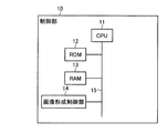
次に、第1印刷装置1の制御部10および第2印刷装置2の制御部20について説明する。図2は、図1に示した第1印刷装置1の制御部10の主要な構成を示すブロック図であり、図3は、図1に示した第2印刷装置2の制御部20の主要な構成を示すブロック図である。   Next, the control unit 10 of the first printing apparatus 1 and the control unit 20 of the second printing apparatus 2 will be described. FIG. 2 is a block diagram showing a main configuration of the control unit 10 of the first printing apparatus 1 shown in FIG. 1, and FIG. 3 shows a main configuration of the control unit 20 of the second printing apparatus 2 shown in FIG. It is a block diagram which shows a structure.

図2に示すように、第1印刷装置1の制御部10は、CPU11、ROM12、RAM13、および、画像形成制御部14を備える。これらCPU11、ROM12、RAM13、および、画像形成制御部14は、システムバス15によって接続されている。   As shown in FIG. 2, the control unit 10 of the first printing apparatus 1 includes a CPU 11, a ROM 12, a RAM 13, and an image formation control unit 14. The CPU 11, ROM 12, RAM 13, and image formation control unit 14 are connected by a system bus 15.

CPU11は、第1印刷装置1の全体の制御を司るとともに、用紙Wの第1面上にマーク41を形成する処理を含む各種の処理を実行する中央処理装置である。   The CPU 11 is a central processing unit that performs overall control of the first printing apparatus 1 and executes various processes including a process of forming the mark 41 on the first surface of the paper W.

ROM12は、CPU11が実行するプログラムを記憶している読み出し専用の記憶手段である。   The ROM 12 is a read-only storage unit that stores a program executed by the CPU 11.

RAM13は、CPU11が実行するプログラムを展開し、各種処理を行う際の作業領域として使用する読み書き可能な記憶手段である。   The RAM 13 is a readable / writable storage means used as a work area when the program executed by the CPU 11 is expanded and various processes are performed.

画像形成制御部14は、CPU11からの指示に基づいて、第1印刷装置1の内部の画像形成部に対する制御を司る。画像形成制御部14は、図1に示した感光体16上へのトナーによる画像(マーク41も含む)の形成と、加熱ローラ17の加熱と、感光体16、加熱ローラ17、加圧ローラ18、送り出しローラ19、および、図示を省略した帯電、露光、現像、除電、クリーニングなどの各手段の駆動制御を行う。   The image forming control unit 14 controls the image forming unit inside the first printing apparatus 1 based on an instruction from the CPU 11. The image forming control unit 14 forms an image (including the mark 41) with toner on the photosensitive member 16 shown in FIG. 1, heats the heating roller 17, and the photosensitive member 16, the heating roller 17, and the pressure roller 18. Then, drive control of the delivery roller 19 and each means such as charging, exposure, development, charge removal, cleaning, etc. (not shown) is performed.

第1印刷装置1においては、例えば、制御部10のCPU11がROM12に記録されているプログラムを実行し、画像形成制御部14に対して指示を与えて画像形成部を制御することにより、用紙W上の第1面に画像とともにマーク41を形成するために必要な機能が実現される。つまり、第1印刷装置1においては、制御部10のCPU11と画像形成制御部14と画像形成部とが、特許請求の範囲に記載の「マーク形成手段」として機能する。   In the first printing apparatus 1, for example, the CPU 11 of the control unit 10 executes a program recorded in the ROM 12, and gives an instruction to the image formation control unit 14 to control the image formation unit. A function necessary for forming the mark 41 together with the image on the first surface is realized. That is, in the first printing apparatus 1, the CPU 11, the image formation control unit 14, and the image formation unit of the control unit 10 function as “mark formation unit” recited in the claims.

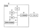
第2印刷装置2の制御部20は、図3に示すように、CPU21、ROM22、RAM23、画像形成制御部24、および、入力制御部25を備える。これらCPU21、ROM22、RAM23、画像形成制御部24、および、入力制御部25は、システムバス26によって接続されている。   As shown in FIG. 3, the control unit 20 of the second printing apparatus 2 includes a CPU 21, a ROM 22, a RAM 23, an image formation control unit 24, and an input control unit 25. The CPU 21, ROM 22, RAM 23, image formation control unit 24, and input control unit 25 are connected by a system bus 26.

CPU21は、第2印刷装置2の全体の制御を司るとともに、マークセンサ31から入力した第1通過時間および第2通過時間に基づいて、用紙Wの副走査伸縮率および主走査伸縮率(マークセンサ31が第1マークセンサ31aと第2マークセンサ31bを有する場合はさらに蛇行量)を算出する処理と、算出した副走査伸縮率および主走査伸縮率に応じて用紙Wの第2面に形成する画像の位置を調整する処理(画像形成のタイミングを調整して画像の位置をずらすものも含む)を含む各種の処理を実行する中央処理装置である。   The CPU 21 governs overall control of the second printing apparatus 2 and, based on the first passage time and the second passage time input from the mark sensor 31, the sub-scanning expansion / contraction ratio and the main scanning expansion / contraction ratio (mark sensor) of the paper W. In the case where the first mark sensor 31a and the second mark sensor 31b 31 have a first mark sensor 31a and a second mark sensor 31b, a process of calculating a meandering amount) and a sub-scanning expansion / contraction ratio and a main-scanning expansion / contraction ratio are formed. This is a central processing unit that executes various processes including a process for adjusting the position of an image (including a process for adjusting the timing of image formation to shift the position of the image).

ROM22は、CPU21が実行するプログラムを記憶している読み出し専用の記憶手段である。   The ROM 22 is a read-only storage unit that stores a program executed by the CPU 21.

RAM23は、CPU21が実行するプログラムを展開し、各種処理を行う際の作業領域として使用する読み書き可能な記憶手段である。   The RAM 23 is a readable / writable storage means used as a work area when the program executed by the CPU 21 is expanded and various processes are performed.

画像形成制御部24は、CPU21からの指示に基づいて、第2印刷装置2の内部の画像形成部に対する制御を司り、図1に示した感光体27上へのトナーによる画像の形成と、上記加熱ローラ28の加熱と、上記感光体27と加熱ローラ28と上記加圧ローラ29と上記送り出しローラ30と、図示を省略した帯電、露光、現像、除電、クリーニングなどの各手段の各駆動制御を行う。   The image forming control unit 24 controls the image forming unit inside the second printing apparatus 2 based on an instruction from the CPU 21. The image forming control unit 24 forms an image with toner on the photosensitive member 27 shown in FIG. The heating control of the heating roller 28, the photosensitive member 27, the heating roller 28, the pressure roller 29, the delivery roller 30, and various means such as charging, exposure, development, charge removal, cleaning, etc., not shown. Do.

入力制御部25は、マークセンサ31から出力される第1通過時間および第2通過時間の情報を入力し、その情報をCPU21へ送る。   The input control unit 25 inputs information on the first passage time and the second passage time output from the mark sensor 31 and sends the information to the CPU 21.

第2印刷装置2においては、例えば、制御部20のCPU21がROM22に記録されているプログラムを実行することにより、マークセンサ31から入力した第1通過時間および第2通過時間に基づいて副走査伸縮率および主走査伸縮率(マークセンサ31が第1マークセンサ31aと第2マークセンサ31bを有する場合はさらに蛇行量)を算出する処理が実現される。また、第2印刷装置2においては、例えば、制御部20のCPU21がROM22に記録されているプログラムを実行し、画像形成制御部24に対して指示を与えて画像形成部を制御することにより、用紙Wの第2面に形成される画像の位置を調整するために必要な機能が実現される。つまり、第2印刷装置2においては、制御部20のCPU21が特許請求の範囲に記載の「算出手段」として機能する。また、第2印刷装置2においては、制御部20のCPU21と画像形成制御部24と画像形成部とが、特許請求の範囲に記載の「画像調整手段」として機能する。   In the second printing apparatus 2, for example, the CPU 21 of the control unit 20 executes a program recorded in the ROM 22, so that the sub-scanning expansion / contraction is performed based on the first passage time and the second passage time input from the mark sensor 31. Processing for calculating the rate and the main scanning expansion / contraction rate (when the mark sensor 31 includes the first mark sensor 31a and the second mark sensor 31b, the amount of meandering) is realized. In the second printing apparatus 2, for example, the CPU 21 of the control unit 20 executes a program recorded in the ROM 22 and gives an instruction to the image formation control unit 24 to control the image formation unit. A function necessary for adjusting the position of the image formed on the second surface of the paper W is realized. That is, in the second printing apparatus 2, the CPU 21 of the control unit 20 functions as “calculation means” described in the claims. In the second printing apparatus 2, the CPU 21, the image formation control unit 24, and the image formation unit of the control unit 20 function as “image adjustment unit” recited in the claims.

次に、マーク41の用紙W上の形成位置について説明する。図4は、図1に示した第1印刷装置1によってマーク41が形成された用紙Wの説明図である。   Next, the formation position of the mark 41 on the paper W will be described. FIG. 4 is an explanatory diagram of the paper W on which the mark 41 is formed by the first printing apparatus 1 shown in FIG.

本実施形態に係る印刷システムで使用する用紙Wとしては、図4(a)に示すように、副走査方向に平行な縁部に送り孔40を設けたタイプと、図4(b)に示すように、送り孔を設けていないタイプとがある。本実施形態では、図4(b)に示したタイプの用紙Wを使用するものとして説明する。なお、図4(a)の送り孔40を設けたタイプの用紙Wを用いる場合、第1印刷装置1と第2印刷装置2には、用紙Wに設けた送り孔40にピンを挿入して係合させることによって用紙Wを搬送する搬送手段を設ける必要があるが、その搬送手段は公知技術なので、詳細な説明は省略する。   As the paper W used in the printing system according to the present embodiment, as shown in FIG. 4A, a type in which the feed hole 40 is provided at the edge parallel to the sub-scanning direction, and as shown in FIG. 4B. Thus, there is a type in which no feed hole is provided. In the present embodiment, description will be made assuming that the paper W of the type shown in FIG. When the paper W of the type provided with the feed hole 40 in FIG. 4A is used, a pin is inserted into the feed hole 40 provided in the paper W in the first printing apparatus 1 and the second printing apparatus 2. Although it is necessary to provide a transporting means for transporting the paper W by being engaged, the transporting means is a well-known technique, and thus detailed description thereof is omitted.

マーク41は、用紙Wの送り孔40の有無に関わらず、第1印刷装置1により、画像データ(印刷データ)に基づく画像Imとともに、各ページの先頭端を含む等間隔の位置(例えば、ページ長L毎の位置)に形成される。上記等間隔の位置については、ページ長Lよりも短い等間隔にしてもよい。なお、本実施形態では、上述したように、第1印刷装置1の制御部10のCPU11がROM12に記録されているプログラムを実行し、画像形成制御部14に対して指示を与えて画像形成部を制御することにより、用紙W上の第1面に画像Imとともにマーク41を形成するために必要な機能が実現される。ただし、マーク41を形成する手段は、画像Imを形成する手段とは独立させて別に設けるようにしてもよい。   Regardless of the presence or absence of the feed hole 40 of the paper W, the mark 41 is printed by the first printing apparatus 1 along with the image Im based on the image data (print data) at equal intervals including the top end of each page (for example, page (Position for each length L). The equidistant positions may be equidistant shorter than the page length L. In the present embodiment, as described above, the CPU 11 of the control unit 10 of the first printing apparatus 1 executes the program recorded in the ROM 12 and gives an instruction to the image formation control unit 14 to provide an image formation unit. By controlling the above, a function necessary for forming the mark 41 together with the image Im on the first surface on the paper W is realized. However, the means for forming the mark 41 may be provided separately from the means for forming the image Im.

第1印刷装置1により第1面にマーク41が形成された用紙Wは、第1印刷装置1から排出され、反転装置3により表裏が反転された後、第2印刷装置2に送られる。これにより、第2印刷装置2においては、マーク41が形成された用紙Wの第1面が、マークセンサ31の検出面と対向するようになり、マークセンサ31によって用紙Wの第1面に形成されたマーク41を検出することが可能になる。   The paper W on which the mark 41 is formed on the first surface by the first printing apparatus 1 is discharged from the first printing apparatus 1, and the front and back are reversed by the reversing apparatus 3, and then sent to the second printing apparatus 2. Accordingly, in the second printing apparatus 2, the first surface of the paper W on which the mark 41 is formed is opposed to the detection surface of the mark sensor 31, and is formed on the first surface of the paper W by the mark sensor 31. The marked mark 41 can be detected.

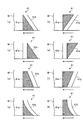
次に、マーク41の具体例について説明する。マーク41は、上述したように、副走査方向の長さが、主操作方向の位置に応じて異なる形状を有する第1マーク部と、第1マーク部の副走査方向と平行な辺を除くいずれかの辺に対して、所定距離を存して平行に配置される線である第2マーク部とを含む。図5は、上記の条件を満たすマーク41の具体例を示す図である。なお、図中の矢印の方向が用紙Wの搬送方向(副走査方向)である。   Next, a specific example of the mark 41 will be described. As described above, the mark 41 has a length in the sub-scanning direction that has a different shape depending on the position in the main operation direction, and any of the marks 41 except for a side parallel to the sub-scanning direction of the first mark portion. And a second mark portion which is a line arranged parallel to the side with a predetermined distance. FIG. 5 is a diagram showing a specific example of the mark 41 that satisfies the above conditions. Note that the direction of the arrow in the figure is the conveyance direction (sub-scanning direction) of the paper W.

図5(a)および図5(b)は、第1マーク部41aを直角三角形の形状とし、第2マーク部41bを、直角三角形の第1マーク部41aの斜辺に対して所定距離を存して平行となるように、第1マーク部41aよりも用紙Wの搬送方向の後段に配置したマーク41の例である。なお、図5(b)に示すマーク41は、図5(a)に示すマーク41を主走査方向に反転させた例である。   5A and 5B, the first mark portion 41a has a right triangle shape, and the second mark portion 41b has a predetermined distance with respect to the hypotenuse of the right triangle first mark portion 41a. This is an example of the mark 41 that is arranged at a later stage in the transport direction of the paper W than the first mark portion 41a so as to be parallel to each other. The mark 41 shown in FIG. 5B is an example in which the mark 41 shown in FIG. 5A is inverted in the main scanning direction.

図5(c)および図5(d)は、第1マーク部41aを直角三角形の形状とし、第2マーク部41bを、直角三角形の第1マーク部41aの長辺に対して所定距離を存して平行となるように、第1マーク部41aよりも用紙Wの搬送方向の前段に配置したマーク41の例である。なお、図5(d)に示すマーク41は、図5(c)に示すマーク41を主走査方向に反転させた例である。   5 (c) and 5 (d), the first mark portion 41a has a right triangle shape, and the second mark portion 41b has a predetermined distance from the long side of the first mark portion 41a of the right triangle. In this example, the marks 41 are arranged in front of the first mark portion 41a in the transport direction of the paper W so as to be parallel to each other. The mark 41 shown in FIG. 5D is an example in which the mark 41 shown in FIG. 5C is reversed in the main scanning direction.

なお、図5(a)〜図5(d)に示すマーク41は、直角三角形の第1マーク部41aの短辺が副走査方向に沿って配置され、長辺が主走査方向に沿って配置されるようにしているが、これとは逆に、直角三角形の第1マーク部41aの長辺が副走査方向に沿って配置され、短辺が主走査方向に沿って配置されるようにしてもよい。また、直角三角形の第1マーク部41aの斜辺を除く2辺の長さが等しい場合は、そのうちの一方の辺(第1辺)が副走査方向に沿って配置され、他方の辺(第2辺)が主走査方向に沿って配置されるようにすればよい。   5A to 5D, the short side of the first mark portion 41a of a right triangle is arranged along the sub-scanning direction, and the long side is arranged along the main scanning direction. However, on the contrary, the long side of the first mark portion 41a of the right triangle is arranged along the sub-scanning direction, and the short side is arranged along the main scanning direction. Also good. When the lengths of the two sides excluding the hypotenuse of the first mark portion 41a of the right triangle are equal, one side (first side) of them is arranged along the sub-scanning direction, and the other side (second side) (Side) may be arranged along the main scanning direction.

図5(e)および図5(f)は、第1マーク部41aを90度の内角を2つ持つ台形の形状とし、第2マーク部41bを、上記台形の第1マーク部41aの斜辺に対して所定距離を存して平行となるように、第1マーク部41aよりも用紙Wの搬送方向の後段に配置したマーク41の例である。なお、図5(f)に示すマーク41は、図5(e)に示すマーク41を主走査方向に反転させた例である。なお、図5(e)および図5(f)に示すマーク41は、第2マーク部41bを第1マーク部41aよりも用紙Wの搬送方向の後段に配置しているが、これとは逆に、第2マーク部41bを第1マーク部41aよりも用紙Wの搬送方向の前段に配置してもよい。   5 (e) and 5 (f), the first mark portion 41a has a trapezoidal shape with two 90 ° inner angles, and the second mark portion 41b is placed on the hypotenuse of the trapezoidal first mark portion 41a. This is an example of the mark 41 arranged at a later stage in the transport direction of the paper W than the first mark portion 41a so as to be parallel with a predetermined distance. Note that the mark 41 shown in FIG. 5F is an example in which the mark 41 shown in FIG. 5E is inverted in the main scanning direction. Note that the mark 41 shown in FIGS. 5E and 5F has the second mark portion 41b disposed at a later stage in the transport direction of the paper W than the first mark portion 41a, but this is opposite. In addition, the second mark portion 41b may be arranged at a preceding stage in the transport direction of the paper W than the first mark portion 41a.

図5(g)は、図5(a)に示した直角三角形の第1マーク部41aの斜辺を2次曲線に置き換えたマーク41の例である。また、図5(h)は、図5(e)に示した台形の第1マーク部41aの斜辺を2次曲線に置き換えたマーク41の例である。なお、ここでは、図5(a)に示した直角三角形の第1マーク部41aの斜辺を2次曲線に置き換えた例と、図5(e)に示した台形の第1マーク部41aの斜辺を2次曲線に置き換えた例を例示するが、図5(a)と図5(e)以外で示した第1マーク部41aの斜辺を2次曲線に置き換えるようにしてもよい。また、マーク41は、図5(a)〜図5(g)で例示した構成に限らず、副走査方向の長さが、主操作方向の位置に応じて異なる形状を有する第1マーク部41aと、第1マーク部41aの副走査方向と平行な辺を除くいずれかの辺に対して、所定距離を存して平行に配置される線である第2マーク部41bとを含む構成であればよい。   FIG. 5G shows an example of the mark 41 in which the hypotenuse of the first mark portion 41a of the right triangle shown in FIG. 5A is replaced with a quadratic curve. FIG. 5H is an example of the mark 41 in which the hypotenuse of the trapezoidal first mark portion 41a shown in FIG. 5E is replaced with a quadratic curve. Here, an example in which the hypotenuse of the right triangle first mark portion 41a shown in FIG. 5A is replaced with a quadratic curve, and the hypotenuse of the trapezoidal first mark portion 41a shown in FIG. 5E. However, the hypotenuse of the first mark portion 41a shown in FIG. 5A and FIG. 5E may be replaced with a quadratic curve. In addition, the mark 41 is not limited to the configuration illustrated in FIGS. 5A to 5G, and the first mark portion 41 a having a shape whose length in the sub-scanning direction varies depending on the position in the main operation direction. And a second mark portion 41b which is a line arranged in parallel with a predetermined distance with respect to any side except the side parallel to the sub-scanning direction of the first mark portion 41a. That's fine.

マーク41が上記のいずれの構成であっても、用紙Wの副走査伸縮率は、第1マーク部41aと第2マーク部42bとの間の所定距離の区間がマーク検出位置を通過している時間である第1通過時間と第1参照時間との比率により求めることができる。ここで第1参照時間とは、用紙Wの副走査方向の長さが変化していない状態(つまり副走査方向の伸縮が生じていない状態)の第1通過時間である。第1参照時間は、予め計測され、第2画像形成装置2の制御部20内部のROM22あるいは別途設けた不揮発性メモリなどの記憶部に格納される。   Regardless of the configuration of the mark 41, the sub-scanning expansion / contraction ratio of the paper W is such that a section of a predetermined distance between the first mark portion 41a and the second mark portion 42b passes the mark detection position. It can be obtained from the ratio of the first transit time, which is time, and the first reference time. Here, the first reference time is a first passage time in a state where the length of the paper W in the sub-scanning direction has not changed (that is, a state in which expansion and contraction in the sub-scanning direction has not occurred). The first reference time is measured in advance and stored in a storage unit such as a ROM 22 in the control unit 20 of the second image forming apparatus 2 or a non-volatile memory provided separately.

また、マーク41が上記のいずれの構成であっても、用紙Wの主走査伸縮率は、例えば、第1マーク部41aがマーク検出位置を通過している時間である第2通過時間と第2参照時間との比率と、副走査伸縮率と、第1マーク部41aの主走査方向の位置に応じた副走査方向の長さの関係を表す関数とにより求めることができる。ここで第2参照時間とは、用紙Wの副走査方向および主走査方向の長さが変化していない状態(つまり副走査方向にも主走査方向にも伸縮が生じていない状態)の第2通過時間である。第2参照時間は、予め計測され、第2画像形成装置2の制御部20内部のROM22あるいは別途設けた不揮発性メモリなどの記憶部に格納される。また、第1マーク部41aの主走査方向の位置に応じた副走査方向の長さの関係を表す関数は、第1マーク部41aの形状から一義的に導かれる関数であり、予め作成されて、第2画像形成装置2の制御部20内部のROM22あるいは別途設けた不揮発性メモリなどの記憶部に格納される。   Further, regardless of the configuration of the mark 41, the main scanning expansion / contraction rate of the paper W is, for example, the second passage time and the second passage time that is the time during which the first mark portion 41a passes the mark detection position. It can be obtained by a function representing the relationship between the ratio to the reference time, the sub-scanning expansion / contraction rate, and the length in the sub-scanning direction according to the position of the first mark portion 41a in the main scanning direction. Here, the second reference time is a second state in which the lengths of the paper W in the sub-scanning direction and the main scanning direction are not changed (that is, no expansion or contraction occurs in the sub-scanning direction or the main scanning direction). It is transit time. The second reference time is measured in advance and stored in a storage unit such as a ROM 22 in the control unit 20 of the second image forming apparatus 2 or a non-volatile memory provided separately. The function representing the relationship in length in the sub-scanning direction according to the position of the first mark portion 41a in the main scanning direction is a function that is uniquely derived from the shape of the first mark portion 41a and is created in advance. These are stored in a storage unit such as a ROM 22 in the control unit 20 of the second image forming apparatus 2 or a non-volatile memory provided separately.

なお、上記の主走査伸縮率の算出方法は、用紙Wが主走査方向に蛇行せずに搬送されていることを前提としており、用紙Wが主走査方向に蛇行しながら搬送されている場合は、その蛇行量に応じて算出結果に誤差が生じる。このような用紙Wの主走査方向の蛇行による影響を排除して主走査伸縮率を正確に算出するには、上述したように、マークセンサ41を、主走査方向における位置が異なる2つのマーク検出位置でマーク41を検出する第1マークセンサ31aおよび第2マークセンサ31bで構成し、2つのマーク検出位置での第2通過時間が得られるようにすることが望ましい。この場合、2つのマーク検出位置の位置関係と、2つのマーク検出位置での第2通過時間とを用いることで、用紙Wが主走査方向に蛇行していたとしても、蛇行の影響を排除した正確な主走査伸縮率が求められるとともに、その蛇行量も求めることができる。   The above-described main scanning expansion / contraction rate calculation method is based on the assumption that the paper W is conveyed without meandering in the main scanning direction, and when the paper W is conveyed while meandering in the main scanning direction. An error occurs in the calculation result according to the meandering amount. In order to eliminate the influence of the meandering of the paper W in the main scanning direction and accurately calculate the main scanning expansion / contraction rate, as described above, the mark sensor 41 detects two marks at different positions in the main scanning direction. It is desirable that the first mark sensor 31a and the second mark sensor 31b that detect the mark 41 at the position are configured so that the second passage time at the two mark detection positions can be obtained. In this case, by using the positional relationship between the two mark detection positions and the second passage time at the two mark detection positions, even if the paper W is meandering in the main scanning direction, the influence of meandering is eliminated. An accurate main scanning expansion / contraction ratio is obtained, and the meandering amount can be obtained.

また、特に、マーク41の第1マーク部41aを直角三角形の形状とし、直角三角形の斜辺を除く2つの辺のうち、主走査方向に沿って配置された辺(第2辺)を3等分する2つの位置で、第1マークセンサ31aおよび第2マークセンサ31bがそれぞれマーク41を検出する構成とすれば、蛇行の影響を排除した主走査伸縮率および蛇行量を、簡単な幾何学計算により算出することが可能となる。以下、マーク41を図5(a)に例示した構成とし、直角三角形の第1マーク部41aの主走査方向に沿って配置された辺(第2辺)を3等分する2つの位置で、第1マークセンサ31aおよび第2マークセンサ31bがそれぞれマーク41を検出する場合を例に挙げ、副走査伸縮率、主走査伸縮率、および、蛇行量を算出する方法について、さらに詳しく説明する。   In particular, the first mark portion 41a of the mark 41 is formed in a right triangle shape, and the side (second side) arranged along the main scanning direction among the two sides excluding the hypotenuse of the right triangle is divided into three equal parts. If the first mark sensor 31a and the second mark sensor 31b detect the mark 41 at the two positions, the main scanning expansion / contraction rate and the meandering amount excluding the influence of meandering can be calculated by simple geometric calculation. It is possible to calculate. Hereinafter, the mark 41 is configured as illustrated in FIG. 5A, and the two positions that divide the side (second side) arranged along the main scanning direction of the first mark portion 41a of the right triangle into three equal parts, Taking the case where the first mark sensor 31a and the second mark sensor 31b detect the mark 41 as an example, a method for calculating the sub-scanning expansion / contraction ratio, the main scanning expansion / contraction ratio, and the meandering amount will be described in more detail.

図6は、図5(a)に例示した構成のマーク41とマークセンサ31との位置関係を説明する図である。なお、図中の矢印の方向が用紙Wの搬送方向(副走査方向)である。図6に示すように、マーク41は、直角三角形の形状を有する第1マーク部41aと、直角三角形の第1マーク部41aの斜辺a1−a3に対して所定距離n(nは正の数)を存して平行に配置された直線a4−a5である第2マーク部41bとを含む。このマーク41は、用紙Wの第1面の搬送方向に平行な縁部に形成される。また、マーク41は、例えば、用紙Wのページ先頭端を含む等間隔の位置に複数形成される。   FIG. 6 is a diagram for explaining the positional relationship between the mark 41 and the mark sensor 31 having the configuration illustrated in FIG. Note that the direction of the arrow in the figure is the conveyance direction (sub-scanning direction) of the paper W. As shown in FIG. 6, the mark 41 has a first mark portion 41a having a right triangle shape and a predetermined distance n (n is a positive number) with respect to the hypotenuse a1-a3 of the first mark portion 41a of the right triangle. And a second mark portion 41b which is a straight line a4-a5 arranged in parallel. The mark 41 is formed on an edge portion parallel to the transport direction of the first surface of the paper W. Also, a plurality of marks 41 are formed at equally spaced positions including, for example, the page leading edge of the paper W.

直角三角形の第1マーク部41aは、短辺a2−a3が副走査方向に沿って配置され、長辺a1−a2が主走査方向に沿って配置されるように、用紙Wの第1面に形成される。また、第2マーク部41bは、第1マーク部41aよりも用紙Wの搬送方向の後段に配置されるように、用紙Wの第1面に形成される。以下、第1マーク部41aの長辺a1−a2の長さ(距離)をRとし、第1マーク部41aの短辺a2−a3の長さ(距離)をmとする。   The first mark portion 41a having a right triangle is formed on the first surface of the paper W such that the short sides a2-a3 are arranged along the sub-scanning direction and the long sides a1-a2 are arranged along the main scanning direction. It is formed. Further, the second mark portion 41b is formed on the first surface of the paper W so as to be arranged at a later stage in the transport direction of the paper W than the first mark portion 41a. Hereinafter, the length (distance) of the long side a1-a2 of the first mark part 41a is R, and the length (distance) of the short side a2-a3 of the first mark part 41a is m.

一方、マークセンサ31は、第1マークセンサ31aと第2マークセンサ31bの2つの検出部を、主走査方向に沿って並べて配置した構成である。これら第1マークセンサ31aと第2マークセンサ31bは、マーク41の第1マーク部41aの長辺a1−a2を3分割する2箇所において、用紙Wの第1面に形成されたマークを検出する。すなわち、第1マークセンサ31aは、直角三角形の第1マーク部41aの頂点a1から頂点a2側にR/3だけシフトした位置でマーク41を検出できるように配置される。また、第2マークセンサ31bは、直角三角形の第1マーク部41aの頂点a2から頂点a1側にR/3だけシフトした位置でマーク41を検出できるように配置される。なお、図6では、第1マークセンサ31aと第2マークセンサ31bを1つの筐体内に配置した例を図示しているが、第1マークセンサ31aと第2マークセンサ31bは、それぞれ個別の筐体内に配置されていてもよい。   On the other hand, the mark sensor 31 has a configuration in which two detection units of the first mark sensor 31a and the second mark sensor 31b are arranged side by side along the main scanning direction. The first mark sensor 31a and the second mark sensor 31b detect marks formed on the first surface of the paper W at two locations where the long side a1-a2 of the first mark portion 41a of the mark 41 is divided into three. . That is, the first mark sensor 31a is arranged so that the mark 41 can be detected at a position shifted by R / 3 from the vertex a1 to the vertex a2 side of the first mark portion 41a having a right triangle. The second mark sensor 31b is arranged so that the mark 41 can be detected at a position shifted by R / 3 from the vertex a2 to the vertex a1 side of the first mark portion 41a having a right triangle. FIG. 6 shows an example in which the first mark sensor 31a and the second mark sensor 31b are arranged in one housing. However, the first mark sensor 31a and the second mark sensor 31b are respectively separate housings. It may be placed in the body.

次に、図6に示した構成において、第2印刷装置2の制御部20が、用紙Wの副走査伸縮率、主走査伸縮率、および、蛇行量を算出する処理の具体例について、さらに詳しく説明する。   Next, in the configuration illustrated in FIG. 6, a specific example of a process in which the control unit 20 of the second printing apparatus 2 calculates the sub-scanning expansion / contraction ratio, the main scanning expansion / contraction ratio, and the meandering amount of the paper W will be described in more detail. explain.

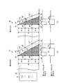
まず、副走査伸縮率を算出する処理について説明する。図7は、第2印刷装置2の制御部20が、用紙Wの副走査伸縮率を算出する処理を説明する図である。図中の一点鎖線で示したラインは、第1マークセンサ31aが配置された主走査方向の位置と、第2マークセンサ31bが配置された主走査方向の位置を示している。また、図中の矢印が用紙Wの搬送方向を示し、用紙Wの搬送速度をv(m/s)とする。   First, processing for calculating the sub-scanning expansion / contraction rate will be described. FIG. 7 is a diagram illustrating a process in which the control unit 20 of the second printing apparatus 2 calculates the sub-scanning expansion / contraction rate of the paper W. A line indicated by a one-dot chain line in the drawing indicates a position in the main scanning direction where the first mark sensor 31a is arranged and a position in the main scanning direction where the second mark sensor 31b is arranged. In addition, an arrow in the figure indicates the conveyance direction of the paper W, and the conveyance speed of the paper W is v (m / s).

図7(a)は、用紙Wに熱作用による伸縮がない状態で、第1マークセンサ31aと第2マークセンサ31bがマーク41を検出する場合を示している。この図7(a)において、第1マーク部41aの3頂点はそれぞれ点a1〜a3で示されており、点a2が直角である。また、第2マーク部41bの両端は、それぞれ点a4、a5で示されている。   FIG. 7A shows a case where the first mark sensor 31a and the second mark sensor 31b detect the mark 41 in a state where the paper W is not expanded or contracted by a thermal action. In FIG. 7A, the three vertices of the first mark portion 41a are indicated by points a1 to a3, respectively, and the point a2 is a right angle. Further, both ends of the second mark portion 41b are indicated by points a4 and a5, respectively.

図7(a)に示す例の場合、第1マークセンサ31aは、マーク41の第1マーク部41aの点a6から点a7までの区間が第1マークセンサ31aの位置(マーク検知位置)を通過している間、第2通過時間T1を表すローレベル信号を出力する。また、第1マークセンサ31aは、マーク41の第1マーク部41aの点a7から第2マーク部41bの点a8までの所定距離(図6に示したn)の区間がマーク検知位置を通過している間、第1通過時間T2を表すハイレベル信号を出力する。   In the case of the example shown in FIG. 7A, in the first mark sensor 31a, the section from the point a6 to the point a7 of the first mark portion 41a of the mark 41 passes the position (mark detection position) of the first mark sensor 31a. During this time, a low level signal representing the second passage time T1 is output. Further, in the first mark sensor 31a, a section of a predetermined distance (n shown in FIG. 6) from the point a7 of the first mark portion 41a of the mark 41 to the point a8 of the second mark portion 41b passes the mark detection position. During this time, a high level signal representing the first passage time T2 is output.

一方、第2マークセンサ31bは、マーク41の第1マーク部41aの点a9から点a10までの区間が第2マークセンサ31bの位置(マーク検知位置)を通過している間、第2通過時間T3を表すローレベル信号を出力する。また、第2マークセンサ31bは、マーク41の第1マーク部41aの点a10から第2マーク部41bの点a11までの所定距離の区間がマーク検知位置を通過している間、第1通過時間T2を表すハイレベル信号を出力する。   On the other hand, the second mark sensor 31b has a second passage time while the section from the point a9 to the point a10 of the first mark portion 41a of the mark 41 passes the position (mark detection position) of the second mark sensor 31b. A low level signal representing T3 is output. Further, the second mark sensor 31b has a first passage time while a section of a predetermined distance from the point a10 of the first mark part 41a of the mark 41 to the point a11 of the second mark part 41b passes the mark detection position. A high level signal representing T2 is output.

ここで、マーク41の第2マーク部41aは、直角三角形の第1マーク部41bの斜辺に対して平行に配置されているため、第1マークセンサ31aから出力される第1通過時間T2と、第2マークセンサ31bから出力される第1通過時間T2は、同じ値である。制御部20のCPU21は、この図7(a)の例のように、熱作用による伸縮がない用紙Wを搬送したときに、第1マークセンサ31aおよび第2マークセンサ31bから出力される第1通過時間T2を、第1参照時間tbとして、ROM22などの記憶部に格納する。   Here, since the second mark portion 41a of the mark 41 is arranged in parallel to the oblique side of the first mark portion 41b having a right triangle, the first passage time T2 output from the first mark sensor 31a, The first passage time T2 output from the second mark sensor 31b has the same value. The CPU 21 of the controller 20 outputs the first mark sensor 31a and the second mark sensor 31b output from the first mark sensor 31a when the paper W that does not expand or contract due to thermal action is conveyed as in the example of FIG. The passage time T2 is stored in the storage unit such as the ROM 22 as the first reference time tb.

図7(b)は、第1面への画像形成時の熱作用により用紙Wが副走査方向に収縮している状態で、第1マークセンサ31aと第2マークセンサ31bがマーク41を検出する場合を示している。この図7(b)において、第1マーク部41aの3頂点はそれぞれ点b1〜b3で示されており、点b2が直角である。また、第2マーク部41bの両端は、それぞれ点b4、b5で示されている。この図7(b)に示すマーク41では、直角三角形の第1マーク部41aの短辺b2−b3が、伸縮のない図7(a)の例の短辺a2−a3よりも短くなっている。また、直角三角形の第1マーク部41aの斜辺b1−b3と第2マーク部41bとの距離も、伸縮のない図7(a)の例と比較して狭くなっている。   FIG. 7B shows the mark 41 detected by the first mark sensor 31a and the second mark sensor 31b in a state where the paper W is contracted in the sub-scanning direction due to thermal action during image formation on the first surface. Shows the case. In FIG. 7B, the three vertices of the first mark portion 41a are indicated by points b1 to b3, respectively, and the point b2 is a right angle. Further, both ends of the second mark portion 41b are indicated by points b4 and b5, respectively. In the mark 41 shown in FIG. 7B, the short side b2-b3 of the first mark portion 41a having a right triangle is shorter than the short side a2-a3 in the example of FIG. . Further, the distance between the hypotenuse b1-b3 of the first mark portion 41a having a right triangle and the second mark portion 41b is also narrower than in the example of FIG.

図7(b)に示す例の場合、第1マークセンサ31aは、マーク41の第1マーク部41aの点b6から点b7までの区間が第1マークセンサ31aの位置(マーク検知位置)を通過している間、第2通過時間t1を表すローレベル信号を出力する。また、第1マークセンサ31aは、マーク41の第1マーク部41aの点b7から第2マーク部41bの点b8までの所定距離の区間がマーク検知位置を通過している間、第1通過時間t2を表すハイレベル信号を出力する。   In the example shown in FIG. 7B, in the first mark sensor 31a, the section from the point b6 to the point b7 of the first mark portion 41a of the mark 41 passes the position (mark detection position) of the first mark sensor 31a. During this time, a low level signal representing the second passage time t1 is output. Further, the first mark sensor 31a has a first passage time while a section of a predetermined distance from the point b7 of the first mark part 41a of the mark 41 to the point b8 of the second mark part 41b passes the mark detection position. A high level signal representing t2 is output.

一方、第2マークセンサ31bは、マーク41の第1マーク部41aの点b9から点b10までの区間が第2マークセンサ31bの位置(マーク検知位置)を通過している間、第2通過時間t3を表すローレベル信号を出力する。また、第2マークセンサ31bは、マーク41の第1マーク部41aの点b10から第2マーク部41bの点b11までの所定距離の区間がマーク検知位置を通過している間、第1通過時間t2を表すハイレベル信号を出力する。   On the other hand, the second mark sensor 31b has a second passage time while the section from the point b9 to the point b10 of the first mark portion 41a of the mark 41 passes the position (mark detection position) of the second mark sensor 31b. A low level signal representing t3 is output. Further, the second mark sensor 31b has a first passage time while a section of a predetermined distance from the point b10 of the first mark part 41a of the mark 41 to the point b11 of the second mark part 41b passes the mark detection position. A high level signal representing t2 is output.

ここで、マーク41の第2マーク部41aは、直角三角形の第1マーク部41bの斜辺に対して平行に配置されているため、用紙Wに副走査方向の伸縮が生じていたとしても、第1マークセンサ31aから出力される第1通過時間t2と、第2マークセンサ31bから出力される第1通過時間t2は、同じ値である。制御部20のCPU21は、これら第1マークセンサ31aおよび第2マークセンサ31bから出力される第1通過時間t2を、副走査伸縮率を求めるための第1通過時間taとして使用する。   Here, since the second mark portion 41a of the mark 41 is arranged in parallel to the oblique side of the first mark portion 41b having a right triangle, even if the paper W is expanded or contracted in the sub-scanning direction, The first passage time t2 output from the first mark sensor 31a and the first passage time t2 output from the second mark sensor 31b are the same value. The CPU 21 of the control unit 20 uses the first passage time t2 output from the first mark sensor 31a and the second mark sensor 31b as the first passage time ta for obtaining the sub-scanning expansion / contraction rate.

用紙Wの副走査伸縮率は、用紙Wに副走査方向の伸縮が生じた場合の第1通過時間と、用紙Wに伸縮が生じていない場合の第1通過時間との比率により算出できる。つまり、副走査伸縮率αは、上記第1参照時間tbと第1通過時間taから、下記式(1)により算出できる。
α=ta/tb ・・・(1)
制御部20のCPU21は、上記式(1)に基づく演算処理によって、用紙Wの副走査伸縮率αを算出する。
The sub-scanning expansion / contraction rate of the paper W can be calculated by a ratio between the first passage time when the paper W is stretched in the sub-scanning direction and the first passage time when the paper W is not stretched. That is, the sub-scanning expansion / contraction rate α can be calculated by the following formula (1) from the first reference time tb and the first passage time ta.
α = ta / tb (1)
The CPU 21 of the control unit 20 calculates the sub-scanning expansion / contraction rate α of the paper W by the arithmetic processing based on the above formula (1).

次に、主走査伸縮率を算出する処理について説明する。図8は、第2印刷装置2の制御部20が、用紙Wの主走査伸縮率を算出する処理を説明する図である。図中の一点鎖線で示したラインは、第1マークセンサ31aが配置された主走査方向の位置と、第2マークセンサ31bが配置された主走査方向の位置を示している。また、図中の矢印が用紙Wの搬送方向を示し、用紙Wの搬送速度をv(m/s)とする。   Next, processing for calculating the main scanning expansion / contraction rate will be described. FIG. 8 is a diagram illustrating a process in which the control unit 20 of the second printing apparatus 2 calculates the main scanning expansion / contraction rate of the paper W. A line indicated by a one-dot chain line in the drawing indicates a position in the main scanning direction where the first mark sensor 31a is arranged and a position in the main scanning direction where the second mark sensor 31b is arranged. In addition, an arrow in the figure indicates the conveyance direction of the paper W, and the conveyance speed of the paper W is v (m / s).

図8(a)は、用紙Wに熱作用による伸縮がない状態で、第1マークセンサ31aと第2マークセンサ31bがマーク41を検出する場合を示している。なお、図8(a)は、先に示した図7(a)と共通なので、ここでは詳細な説明を省略する。   FIG. 8A shows a case where the first mark sensor 31a and the second mark sensor 31b detect the mark 41 in a state where the paper W is not expanded or contracted by a thermal action. Since FIG. 8A is common to FIG. 7A described above, detailed description thereof is omitted here.

図8(b)は、第1面への画像形成時の熱作用により用紙Wが主走査方向に収縮している状態で、第1マークセンサ31aと第2マークセンサ31bがマーク41を検出する場合を示している。この図8(b)において、第1マーク部41aの3頂点はそれぞれ点c1〜c3で示されており、点c2が直角である。また、第2マーク部41bの両端は、それぞれ点c4、c5で示されている。この図8(b)に示すマーク41では、直角三角形の第1マーク部41aの長辺c1−c2が、伸縮のない図8(a)の例の長辺a1−a2よりも短くなっている。   FIG. 8B shows the first mark sensor 31a and the second mark sensor 31b detecting the mark 41 in a state where the paper W is contracted in the main scanning direction due to the thermal action during image formation on the first surface. Shows the case. In FIG. 8B, the three vertices of the first mark portion 41a are indicated by points c1 to c3, respectively, and the point c2 is a right angle. Further, both ends of the second mark portion 41b are indicated by points c4 and c5, respectively. In the mark 41 shown in FIG. 8B, the long side c1-c2 of the first mark portion 41a having a right triangle is shorter than the long side a1-a2 in the example of FIG. .

図8(b)に示す例の場合、第1マークセンサ31aは、マーク41の第1マーク部41aの点c6から点c7までの区間が第1マークセンサ31aの位置(マーク検知位置)を通過している間、第2通過時間t1を表すローレベル信号を出力する。また、第1マークセンサ31aは、マーク41の第1マーク部41aの点c7から第2マーク部41bの点c8までの所定距離の区間がマーク検知位置を通過している間、第1通過時間t2を表すハイレベル信号を出力する。   In the case of the example shown in FIG. 8B, in the first mark sensor 31a, the section from the point c6 to the point c7 of the first mark portion 41a of the mark 41 passes the position (mark detection position) of the first mark sensor 31a. During this time, a low level signal representing the second passage time t1 is output. Further, the first mark sensor 31a has a first passage time while a section of a predetermined distance from the point c7 of the first mark portion 41a of the mark 41 to the point c8 of the second mark portion 41b passes the mark detection position. A high level signal representing t2 is output.

一方、第2マークセンサ31bは、マーク41の第1マーク部41aの点c9から点c10までの区間が第2マークセンサ31bの位置(マーク検知位置)を通過している間、第2通過時間t3を表すローレベル信号を出力する。また、第2マークセンサ31bは、マーク41の第1マーク部41aの点c10から第2マーク部41bの点c11までの所定距離の区間がマーク検知位置を通過している間、第1通過時間t2を表すハイレベル信号を出力する。   On the other hand, the second mark sensor 31b has a second passage time while the section from the point c9 to the point c10 of the first mark portion 41a of the mark 41 passes the position (mark detection position) of the second mark sensor 31b. A low level signal representing t3 is output. Further, the second mark sensor 31b has a first passage time while a section of a predetermined distance from the point c10 of the first mark part 41a of the mark 41 to the point c11 of the second mark part 41b passes the mark detection position. A high level signal representing t2 is output.

制御部20のCPU21は、まず、第1マークセンサ31aおよび第2マークセンサ31bから出力される第1通過時間t2を、副走査伸縮率を求めるための第1通過時間taとして使用する。そして、制御部20のCPU21は、上記第1参照時間tbと第1通過時間taから、上記式(1)に基づく演算処理によって、用紙Wの副走査伸縮率αを算出する。   First, the CPU 21 of the control unit 20 uses the first passage time t2 output from the first mark sensor 31a and the second mark sensor 31b as the first passage time ta for obtaining the sub-scanning expansion / contraction rate. Then, the CPU 21 of the control unit 20 calculates the sub-scanning expansion / contraction rate α of the paper W from the first reference time tb and the first passage time ta through the arithmetic processing based on the formula (1).

さらに、制御部20のCPU21は、第1マークセンサ31aから出力される第2通過時間t1を、主走査伸縮率を求めるための第2通過時間tcとして使用する。また、第2マークセンサ31bから出力される第2通過時間t3を、主走査伸縮率を求めるための第2通過時間tdとして使用する。そして、制御部20のCPU21は、2つの第2通過時間tc,tdと、先に求めた用紙Wの副走査伸縮率αと、第1マーク部41aの短辺a2−a3の長さmと、用紙Wの搬送速度vから、下記式(2)に基づく演算処理によって、用紙Wの主走査伸縮率βを算出する。
β=(1/3)×(α×(m/v))/(td−tc) ・・・(2)
Further, the CPU 21 of the control unit 20 uses the second passage time t1 output from the first mark sensor 31a as the second passage time tc for obtaining the main scanning expansion / contraction rate. The second passage time t3 output from the second mark sensor 31b is used as the second passage time td for obtaining the main scanning expansion / contraction rate. Then, the CPU 21 of the control unit 20 includes the two second passage times tc and td, the sub-scanning expansion / contraction rate α of the paper W obtained previously, and the length m of the short side a2-a3 of the first mark unit 41a. The main scanning expansion / contraction rate β of the paper W is calculated from the transport speed v of the paper W by a calculation process based on the following equation (2).
β = (1/3) × (α × (m / v)) / (td−tc) (2)

主走査伸縮率βは、伸縮のない場合の第1マーク部41aの長辺a1−a2の長さRと、伸縮のあった場合の第1マーク部41aの長辺c1−c2の長さyとに基づいて、β=y/Rから算出することができる。また、伸縮のあった場合の第1マーク部41aの長辺c1−c2の長さyについては、直角三角形の相似関係に基いて求めることができる。   The main scanning expansion / contraction ratio β is determined by the length R of the long side a1-a2 of the first mark portion 41a when there is no expansion / contraction, and the length y of the long side c1-c2 of the first mark portion 41a when expansion / contraction occurs. Can be calculated from β = y / R. In addition, the length y of the long sides c1-c2 of the first mark portion 41a when stretched can be obtained based on the similarity of right-angled triangles.

図8(b)に示すように、c1〜c3を頂点とする直角三角形の第1マーク部41aと、c12〜c14を頂点とする直角三角形とは、2つの内角が等しいので相似関係にあり、2辺の長さの比が互いに等しくなる。すなわち、辺c1−c2の長さ(=y)と辺c2−c3の長さ(副走査方向に伸縮のない状態の短辺a2−a3の長さmに副走査伸縮率αを乗算した値)の比と、辺c12−c13の長さ(=R/3)と辺c13−c14の長さの比とが等しくなる。   As shown in FIG. 8 (b), the first mark portion 41a of the right triangle having the vertices c1 to c3 and the right triangle having the vertices of c12 to c14 are similar because the two interior angles are equal, The ratio of the lengths of the two sides becomes equal to each other. That is, the length of the side c1-c2 (= y) and the length of the side c2-c3 (the value obtained by multiplying the length m of the short side a2-a3 in the sub-scanning direction without expansion / contraction by the sub-scanning expansion / contraction rate α. ) And the ratio of the length of the side c12-c13 (= R / 3) to the length of the side c13-c14.

ここで、辺c13−c14の長さに、第2マークセンサ31bから出力される第2通過時間t3と第1マークセンサ31aから出力される第2通過時間t1との差分(t3−t1)を対応させると、y:R/3=(α×m/v):(t3−t1)から、y/R=(1/3)×(α×(m/v))×(1/(t3−t1))が得られる。したがって、β=y/Rと、y/R=(1/3)×(α×(m/v))×(1/(t3−t1))とから、β=(1/3)×(α×(m/v))×(1/(t3−t1))が得られる。ここで、第1マークセンサ31aから出力される第2通過時間t1をtc、第2マークセンサ31bから出力される第2通過時間t3をtdに置き換えると、上記式(2)が得られる。   Here, the difference (t3−t1) between the second passage time t3 output from the second mark sensor 31b and the second passage time t1 output from the first mark sensor 31a is set to the length of the side c13-c14. In correspondence, from y: R / 3 = (α × m / v) :( t3−t1), y / R = (1/3) × (α × (m / v)) × (1 / (t3 -T1)) is obtained. Therefore, from β = y / R and y / R = (1/3) × (α × (m / v)) × (1 / (t3−t1)), β = (1/3) × ( α × (m / v)) × (1 / (t3−t1)) is obtained. Here, when the second passage time t1 output from the first mark sensor 31a is replaced with tc and the second passage time t3 output from the second mark sensor 31b is replaced with td, the above equation (2) is obtained.

したがって、制御部20のCPU21は、マークセンサ31から出力される2つの第2通過時間tc,tdと、用紙Wの副走査伸縮率αと、第1マーク部41aの短辺a2−a3の長さmと、用紙Wの搬送速度vから、上記式(2)に基づく演算処理によって、用紙Wの主走査伸縮率βを算出することができる。なお、用紙Wが主走査方向にのみ伸縮している場合は、α=1となる。   Therefore, the CPU 21 of the control unit 20 includes the two second passage times tc and td output from the mark sensor 31, the sub-scanning expansion / contraction ratio α of the paper W, and the length of the short side a2-a3 of the first mark unit 41a. The main scanning expansion / contraction rate β of the paper W can be calculated from the length m and the conveyance speed v of the paper W by the arithmetic processing based on the above equation (2). Note that α = 1 when the paper W expands and contracts only in the main scanning direction.

次に、蛇行量を算出する処理について説明する。図9は、第2印刷装置2の制御部20が、用紙Wの蛇行量を算出する処理を説明する図である。図中の一点鎖線で示したラインは、第1マークセンサ31aが配置された主走査方向の位置と、第2マークセンサ31bが配置された主走査方向の位置を示している。また、図中の矢印が用紙Wの搬送方向を示し、用紙Wの搬送速度をv(m/s)とする。   Next, a process for calculating the meandering amount will be described. FIG. 9 is a diagram illustrating a process in which the control unit 20 of the second printing apparatus 2 calculates the meandering amount of the paper W. A line indicated by a one-dot chain line in the drawing indicates a position in the main scanning direction where the first mark sensor 31a is arranged and a position in the main scanning direction where the second mark sensor 31b is arranged. In addition, an arrow in the figure indicates the conveyance direction of the paper W, and the conveyance speed of the paper W is v (m / s).

図9(a)は、用紙Wが蛇行していない状態で、第1マークセンサ31aと第2マークセンサ31bがマーク41を検出する場合を示している。なお、図9(a)は、先に示した図7(a)および図8(a)と共通なので、ここでは詳細な説明を省略する。   FIG. 9A shows a case where the first mark sensor 31a and the second mark sensor 31b detect the mark 41 in a state where the paper W is not meandering. Since FIG. 9A is common to FIGS. 7A and 8A described above, detailed description thereof is omitted here.

図9(b)は、用紙Wが主走査方向に蛇行している状態で、第1マークセンサ31aと第2マークセンサ31bがマーク41を検出する場合を示している。この図9(b)において、第1マーク部41aの3頂点はそれぞれ点d1〜d3で示されており、点d2が直角である。   FIG. 9B shows a case where the first mark sensor 31a and the second mark sensor 31b detect the mark 41 in a state where the paper W meanders in the main scanning direction. In FIG. 9B, the three vertices of the first mark portion 41a are indicated by points d1 to d3, respectively, and the point d2 is a right angle.

図9(b)に示す例の場合、第1マークセンサ31aは、マーク41の第1マーク部41aの点d6から点d7までの区間が第1マークセンサ31aの位置(マーク検知位置)を通過している間、第2通過時間t1を表すローレベル信号を出力する。また、第1マークセンサ31aは、マーク41の第1マーク部41aの点d7から第2マーク部41bの点d8までの所定距離の区間がマーク検知位置を通過している間、第1通過時間t2を表すハイレベル信号を出力する。   In the case of the example shown in FIG. 9B, the first mark sensor 31a is such that the section from the point d6 to the point d7 of the first mark portion 41a of the mark 41 passes the position (mark detection position) of the first mark sensor 31a. During this time, a low level signal representing the second passage time t1 is output. Further, the first mark sensor 31a has a first passage time while a section of a predetermined distance from the point d7 of the first mark portion 41a of the mark 41 to the point d8 of the second mark portion 41b passes the mark detection position. A high level signal representing t2 is output.

一方、第2マークセンサ31bは、マーク41の第1マーク部41aの点d9から点d10までの区間が第2マークセンサ31bの位置(マーク検知位置)を通過している間、第2通過時間t3を表すローレベル信号を出力する。また、第2マークセンサ31bは、マーク41の第1マーク部41aの点d10から第2マーク部41bの点d11までの所定距離の区間がマーク検知位置を通過している間、第1通過時間t2を表すハイレベル信号を出力する。   On the other hand, the second mark sensor 31b has a second passage time while the section from the point d9 to the point d10 of the first mark portion 41a of the mark 41 passes the position (mark detection position) of the second mark sensor 31b. A low level signal representing t3 is output. Further, the second mark sensor 31b has a first passage time while a section of a predetermined distance from the point d10 of the first mark part 41a of the mark 41 to the point d11 of the second mark part 41b passes the mark detection position. A high level signal representing t2 is output.

制御部20のCPU21は、まず、第1マークセンサ31aおよび第2マークセンサ31bから出力される第1通過時間t2を、副走査伸縮率を求めるための第1通過時間taとして使用する。そして、制御部20のCPU21は、上記第1参照時間tbと第1通過時間taから、上記式(1)に基づく演算処理によって、用紙Wの副走査伸縮率αを算出する。   First, the CPU 21 of the control unit 20 uses the first passage time t2 output from the first mark sensor 31a and the second mark sensor 31b as the first passage time ta for obtaining the sub-scanning expansion / contraction rate. Then, the CPU 21 of the control unit 20 calculates the sub-scanning expansion / contraction rate α of the paper W from the first reference time tb and the first passage time ta through the arithmetic processing based on the formula (1).

また、制御部20のCPU21は、第1マークセンサ31aから出力される第2通過時間t1を、主走査伸縮率を求めるための第2通過時間tcとして使用する。また、第2マークセンサ31bから出力される第2通過時間t3を、主走査伸縮率を求めるための第2通過時間tdとして使用する。そして、制御部20のCPU21は、2つの第2通過時間tc,tdと、先に求めた用紙Wの副走査伸縮率αと、第1マーク部41aの短辺a2−a3の長さmと、用紙Wの搬送速度vから、上記式(2)に基づく演算処理によって、用紙Wの主走査伸縮率βを算出する。   Further, the CPU 21 of the control unit 20 uses the second passage time t1 output from the first mark sensor 31a as the second passage time tc for obtaining the main scanning expansion / contraction rate. The second passage time t3 output from the second mark sensor 31b is used as the second passage time td for obtaining the main scanning expansion / contraction rate. Then, the CPU 21 of the control unit 20 includes the two second passage times tc and td, the sub-scanning expansion / contraction rate α of the paper W obtained previously, and the length m of the short side a2-a3 of the first mark unit 41a. The main scanning expansion / contraction rate β of the paper W is calculated from the transport speed v of the paper W by the arithmetic processing based on the above equation (2).

さらに、制御部20のCPU21は、2つの第2通過時間tc,tdと、先に求めた用紙Wの主走査伸縮率βと、第1マーク部41aの長辺a1−a2の長さRから、下記式(3)に基づく演算処理によって、用紙Wの蛇行量Sを算出する。
S=R/3×[tc/(td−tc)−1]×β ・・・(3)
Further, the CPU 21 of the control unit 20 determines from the two second passage times tc and td, the main scanning expansion / contraction ratio β of the paper W previously obtained, and the length R of the long side a1-a2 of the first mark portion 41a. The meandering amount S of the paper W is calculated by an arithmetic process based on the following equation (3).
S = R / 3 × [tc / (td−tc) −1] × β (3)

図9(a)と図9(b)を比較すると分かるように、図9(b)に示す第1マーク部41aの点d1から点d6までの長さxは、図9(a)に示す第1マーク部41aの点a1から点a6までの長さR/3に対して、主走査方向の伸縮と蛇行が加わった長さである。つまり、x=(S+R/3)×βとなる。   As can be seen by comparing FIG. 9 (a) and FIG. 9 (b), the length x from the point d1 to the point d6 of the first mark portion 41a shown in FIG. 9 (b) is shown in FIG. 9 (a). This is a length obtained by adding expansion and contraction in the main scanning direction and meandering to the length R / 3 from the point a1 to the point a6 of the first mark portion 41a. That is, x = (S + R / 3) × β.

また、図9(b)に示すように、d1、d6、d7を頂点とする直角三角形と、d7、d12、d10を頂点とする直角三角形とは2つの内角が等しいので相似関係にあり、2辺の長さの比が互いに等しくなる。すなわち、辺d1−d6の長さ(=x)と辺d6−d7の長さの比と、辺d7−d12の長さ(=R/3)と辺c12−c10の長さの比とが等しくなる。   Further, as shown in FIG. 9B, the right triangle having the vertices d1, d6, and d7 and the right triangle having the vertices d7, d12, and d10 have a similar relationship because the two inner angles are equal. The side length ratios are equal to each other. That is, the ratio of the length of the side d1-d6 (= x) to the length of the side d6-d7 and the ratio of the length of the side d7-d12 (= R / 3) to the length of the side c12-c10 are as follows. Will be equal.

ここで、辺d6−d7の長さに第1マークセンサ31aから出力される第2通過時間t1を対応させ、辺d9−d10の長さに第2マークセンサ31bから出力される第2通過時間t3を対応させると、x:R/3=t1:(t3−t1)となり、x=((R/3)×t1)/(t3−t1)が得られる。したがって、x=(S+R/3)×βと、x=((R/3)×t1)/(t3−t1)とから、S=(R/3)×((t1/(t3−t1))−1)×βが得られる。ここで、第1マークセンサ31aから出力される第2通過時間t1をtc、第2マークセンサ31bから出力される第2通過時間t3をtdに置き換えると、上記式(3)が得られる。   Here, the second passage time t1 output from the first mark sensor 31a corresponds to the length of the side d6-d7, and the second passage time output from the second mark sensor 31b to the length of the side d9-d10. When t3 is made to correspond, x: R / 3 = t1: (t3-t1) is obtained, and x = ((R / 3) × t1) / (t3-t1) is obtained. Therefore, from x = (S + R / 3) × β and x = ((R / 3) × t1) / (t3−t1), S = (R / 3) × ((t1 / (t3−t1)) ) -1) × β is obtained. Here, when the second passage time t1 output from the first mark sensor 31a is replaced with tc and the second passage time t3 output from the second mark sensor 31b is replaced with td, the above equation (3) is obtained.

したがって、制御部20のCPU21は、マークセンサ31から出力される2つの第2通過時間tc,tdと、用紙Wの主走査伸縮率βと、第1マーク部41aの長辺a1−a2の長さRから、上記式(3)に基づく演算処理によって、用紙Wの蛇行量Sを算出することができる。なお、この蛇行量Sは、図9中の白抜き矢印で示すように、+方向に蛇行した場合はS>0であり、−方向に蛇行した場合はS<0であり、蛇行していない場合はS=0である。   Therefore, the CPU 21 of the control unit 20 includes the two second passage times tc and td output from the mark sensor 31, the main scanning expansion / contraction rate β of the paper W, and the lengths of the long sides a1-a2 of the first mark unit 41a. From the thickness R, the meandering amount S of the paper W can be calculated by the arithmetic processing based on the above formula (3). The meandering amount S is S> 0 when meandering in the + direction, and S <0 when meandering in the negative direction, as indicated by the white arrow in FIG. In this case, S = 0.

以上のように算出した蛇行量Sは、その値が、第1マーク部41aの長辺a1−a2の長さRの1/3以下の場合に有効値とする。算出した蛇行量SがR/3を超えている場合は、上記式(3)で算出される蛇行量Sとして適正でない。このため、R/3を超えた値として算出された蛇行量Sを無効とし、R/3以下の場合のみ有効値とすることで、算出結果の信頼性を確保できる。   The meandering amount S calculated as described above is an effective value when the value is 1/3 or less of the length R of the long side a1-a2 of the first mark portion 41a. When the calculated meandering amount S exceeds R / 3, the meandering amount S calculated by the above formula (3) is not appropriate. For this reason, the reliability of the calculation result can be ensured by invalidating the meandering amount S calculated as a value exceeding R / 3 and setting it as an effective value only when R / 3 or less.

また、マークセンサ31がマーク41を検出中に用紙Wが蛇行した場合、上記式(3)に基づく演算処理では正確な蛇行量Sを算出できない。このため、蛇行量Sを算出する際は、用紙Wの第1面に形成された複数のマーク41をマーク31が検出するたびに算出される複数の蛇行量Sの平均値を求め、これを有効な蛇行量として用いることが望ましい。これにより、マーク検出中の蛇行などに起因する誤差を抑制することができる。   In addition, when the paper W meanders while the mark sensor 31 is detecting the mark 41, an accurate meandering amount S cannot be calculated by the arithmetic processing based on the above equation (3). Therefore, when calculating the meandering amount S, an average value of the plurality of meandering amounts S calculated each time the mark 31 detects the plurality of marks 41 formed on the first surface of the paper W is obtained. It is desirable to use it as an effective meandering amount. As a result, errors caused by meandering during mark detection can be suppressed.

以上のように算出された蛇行量Sは、例えば、第2印刷装置2において実行される蛇行補正処理における補正データとして使用することができる。なお、長尺の用紙Wの主走査方向の蛇行を補正する蛇行補正処理は公知の技術であるため、ここでは詳細な説明は省略する。   The meandering amount S calculated as described above can be used, for example, as correction data in the meandering correction process executed in the second printing apparatus 2. The meandering correction process for correcting the meandering of the long paper W in the main scanning direction is a well-known technique, and thus detailed description thereof is omitted here.

また、上記の副走査伸縮率および主走査伸縮率は、用紙Wの第2面に形成する画像の位置を、第1面に形成された画像の位置に合わせるためのデータとして使用できる。すなわち、用紙Wの副走査方向については、算出された副走査伸縮率に応じて、例えば、用紙Wを搬送する搬送モータ(図示を省略する)の回転数または感光体27を回転させる感光体モータ(図示を省略する)を制御して、用紙Wの第2面に形成する画像の副走査方向の倍率を調整することで、第1面に形成された画像に対して、第2面に形成する画像の副走査方向における位置を合わせることができる。また、主走査方向については、算出された主走査伸縮率に応じて、例えば、用紙Wの第2面に形成する画像のドット周波数を制御して、用紙Wの第2面に形成する画像の主走査方向の倍率を調整することで、第1面に形成された画像に対して、第2面に形成する画像の主走査方向における位置を合わせることができる。   The sub-scanning expansion / contraction ratio and the main scanning expansion / contraction ratio can be used as data for matching the position of the image formed on the second surface of the paper W with the position of the image formed on the first surface. That is, with respect to the sub-scanning direction of the paper W, for example, according to the calculated sub-scanning expansion / contraction ratio, for example, the number of rotations of a transport motor (not shown) that transports the paper W or a photoconductor motor that rotates the photoconductor 27. By controlling (not shown) and adjusting the magnification in the sub-scanning direction of the image formed on the second surface of the paper W, the image formed on the first surface is formed on the second surface. The position in the sub-scanning direction of the image to be adjusted can be adjusted. In the main scanning direction, for example, the dot frequency of the image formed on the second surface of the paper W is controlled according to the calculated main scanning expansion / contraction ratio, and the image formed on the second surface of the paper W is controlled. By adjusting the magnification in the main scanning direction, the position of the image formed on the second surface in the main scanning direction can be aligned with the image formed on the first surface.

以上、具体的な例を挙げながら詳細に説明したように、本実施形態に係る印刷システムによれば、第1印刷装置1が用紙Wにマーク41を形成し、第2印刷装置2がこのマーク41をマークセンサ31で検出して、用紙Wの副走査伸縮率および主走査伸縮率を算出するようにしているので、第1印刷装置1による用紙Wの第1面への画像形成時における熱作用により用紙Wが副走査方向だけでなく主走査方向に伸縮した場合であっても、算出した副走査伸縮率および副走査伸縮率に応じて、第2印刷装置2が用紙Wの第2面に形成する画像を調整することで、用紙Wの第1面と第2面とで画像の位置を適切に揃えることができる。   As described above in detail with specific examples, according to the printing system according to the present embodiment, the first printing apparatus 1 forms the mark 41 on the paper W, and the second printing apparatus 2 uses this mark. 41 is detected by the mark sensor 31 to calculate the sub-scanning expansion / contraction rate and the main-scanning expansion / contraction rate of the paper W, so that heat is generated when the first printing apparatus 1 forms an image on the first surface of the paper W. Even when the paper W expands and contracts not only in the sub-scanning direction but also in the main scanning direction due to the action, the second printing apparatus 2 causes the second surface of the paper W to change according to the calculated sub-scanning expansion / contraction rate and sub-scanning expansion / contraction rate By adjusting the image to be formed, the position of the image can be appropriately aligned on the first surface and the second surface of the paper W.

また、本実施形態に係る印刷システムによれば、マークセンサ31が第1マークセンサ31aおよび第2マークセンサ31bの2つの検知部を持ち、これら第1マークセンサ31aおよび第2マークセンサ31bが、主走査方向の位置が異なる2つのマーク検出位置でそれぞれマーク41を検出する構成とすることにより、用紙Wが主走査方向に蛇行している場合であっても主走査伸縮率を正しく算出できるとともに、その蛇行量も算出することができる。つまり、長尺の用紙Wの両面に画像を形成する場合、第1面への画像形成時の熱作用により用紙Wの副走査方向および主走査方向の伸縮と用紙Wの主走査方向の蛇行とが同時に発生することも考えられるが、本実施形態に係る印刷システムによれば、用紙Wの副走査方向の伸縮、主走査方向の伸縮、および、主走査方向の蛇行の組み合わせのうち、どの組み合わせが発生したとしても、副走査伸縮率、主走査伸縮率、および、蛇行量をそれぞれ適切に算出することができる。したがって、用紙Wの第1面と第2面の画像の位置合わせを適切に実施できるとともに、蛇行補正処理も適切に行うことができ、用紙Wの第1面と第2面に形成される画像の品位を高めることができる。   Further, according to the printing system according to the present embodiment, the mark sensor 31 has two detection units, the first mark sensor 31a and the second mark sensor 31b, and the first mark sensor 31a and the second mark sensor 31b are By adopting a configuration in which the mark 41 is detected at each of two mark detection positions having different positions in the main scanning direction, the main scanning expansion / contraction ratio can be correctly calculated even when the paper W meanders in the main scanning direction. The meandering amount can also be calculated. That is, when images are formed on both sides of a long sheet W, the expansion and contraction of the sheet W in the sub-scanning direction and the main scanning direction and the meandering of the sheet W in the main scanning direction are caused by the thermal action during image formation on the first surface. However, according to the printing system according to the present embodiment, any combination of the expansion / contraction of the paper W in the sub-scanning direction, the expansion / contraction in the main scanning direction, and the meandering in the main scanning direction is selected. Even if this occurs, the sub-scanning expansion / contraction ratio, the main scanning expansion / contraction ratio, and the meandering amount can be calculated appropriately. Accordingly, it is possible to appropriately align the images on the first and second surfaces of the paper W, and to appropriately perform meandering correction processing, and images formed on the first and second surfaces of the paper W. Can improve the quality.

また、本実施形態に係る印刷システムによれば、単一のマーク41を用いて用紙Wが熱作用によって伸縮した場合の副走査伸縮率および主走査伸縮率と、用紙Wの伸縮による主走査方向の蛇行量がそれぞれ算出可能であるため、用途別のマークを予め準備する必要がない。したがって、用紙Wの印刷領域の拡大に繋がり、また、用紙の蛇行を検出する蛇行センサを別途設けなくても済むことから、印刷システムを安価に構成することができる。   Further, according to the printing system according to the present embodiment, the sub-scanning expansion / contraction ratio and the main scanning expansion / contraction ratio when the paper W is expanded / contracted by a thermal action using the single mark 41, and the main scanning direction due to the expansion / contraction of the paper W Therefore, it is not necessary to prepare a mark for each application in advance. Therefore, the printing area of the paper W is expanded, and it is not necessary to provide a meandering sensor for detecting the meandering of the paper, so that the printing system can be configured at low cost.

また、本実施形態に係る印刷システムによれば、用紙Wの副走査伸縮率については、予め用紙Wに伸縮のない状態で算出された第1通過時間(第1マーク部41aと第2マーク部41bとの間の所定距離の区間がマーク検出位置を通過している時間)を第1参照時間として記憶部(RAM22等)に記憶させておくことで、その後、用紙Wに副走査方向の伸縮が生じた場合に得られる第1通過時間と第1参照時間との比率を求めるといった簡単な方法(上記式(1)による演算)で、副走査伸縮率を算出することができる。   Further, according to the printing system according to the present embodiment, the sub-scanning expansion / contraction rate of the paper W is calculated based on the first passage time (first mark portion 41a and second mark portion) calculated in advance without the paper W being stretched / contracted. The time during which a section of a predetermined distance from 41b passes the mark detection position) is stored in the storage unit (such as the RAM 22) as the first reference time, and then the paper W is expanded or contracted in the sub-scanning direction. The sub-scanning expansion / contraction rate can be calculated by a simple method (calculation according to the above equation (1)) such as obtaining the ratio between the first passage time and the first reference time obtained when the above occurs.

また、本実施形態に係る印刷システムによれば、マーク41の第1マーク部41aを直角三角形の形状とすることで、用紙Wの蛇行の影響を排除した主走査伸縮率および蛇行量を、簡単な幾何学計算により算出することが可能となる。具体的には、上記式(2)により、用紙Wの蛇行の影響を排除した主走査伸縮率を適切に算出できるとともに、式(3)により、用紙Wの蛇行量を適切に算出することができる。   Further, according to the printing system according to the present embodiment, the first mark portion 41a of the mark 41 has a right triangle shape, so that the main scanning expansion / contraction rate and the amount of meandering without the influence of the meandering of the paper W can be simplified. It can be calculated by simple geometric calculation. Specifically, the main scanning expansion / contraction rate excluding the influence of the meandering of the paper W can be calculated appropriately by the above equation (2), and the meandering amount of the paper W can be appropriately calculated by the equation (3). it can.

また、本実施形態に係る印刷システムによれば、マーク41を、第1マーク部41aの主走査方向に沿う辺が用紙Wの第1面に対する画像の書き出し位置に配置されるように、用紙Wの第1面に形成し、第1マーク部41aの主走査方向に沿う辺が検出されるタイミングに基づいて、用紙Wの第2面に対する画像の書き出し位置を調整することで、用紙Wの第1面と第2面とで画像の書き出し位置を合わせることもできる。   Further, according to the printing system according to the present embodiment, the mark 41 is placed on the paper W such that the side along the main scanning direction of the first mark portion 41 a is arranged at the image writing position on the first surface of the paper W. The image writing position on the second surface of the paper W is adjusted on the basis of the timing at which the side along the main scanning direction of the first mark portion 41a is detected. The image writing position can be matched between the first side and the second side.

(第2の実施形態)
次に、第2の実施形態について説明する。本実施形態に係る印刷システムは、第1印刷装置1にマーク41の濃度を検出する濃度センサを設け、この濃度センサにより検出されたマーク41の濃度に応じて、第2印刷装置2のマークセンサ31の感度を調整するようにしたものである。なお、その他の構成は第1の実施形態と共通であるため、以下、第1の実施形態と共通の構成については同一の符号を付して詳細な説明を省略し、本実施形態に特有の構成についてのみ説明する。
(Second Embodiment)
Next, a second embodiment will be described. The printing system according to the present embodiment includes a density sensor that detects the density of the mark 41 in the first printing apparatus 1, and the mark sensor of the second printing apparatus 2 according to the density of the mark 41 detected by the density sensor. The sensitivity of 31 is adjusted. Since other configurations are the same as those in the first embodiment, the same components as those in the first embodiment are denoted by the same reference numerals and detailed description thereof is omitted, and specific to the present embodiment. Only the configuration will be described.

図10は、第1印刷装置1における濃度センサ50の配置の具体例を説明する図である。なお、図中の白抜き矢印は用紙Wの搬送方向を示している。本実施形態に係る印刷システムでは、第1印刷装置1に濃度センサ50が設けられている。濃度センサ50は、用紙Wの第1面に形成されたマーク41の濃度を検出するものである。なお、濃度センサ50は、第2印刷装置2のマークセンサ31と同じ構成のセンサを利用することができる。濃度センサ50として、マークセンサ31と同じ構成のセンサを利用するようにすれば、部品の共通化によるコスト低減が期待できる。   FIG. 10 is a diagram illustrating a specific example of the arrangement of the density sensor 50 in the first printing apparatus 1. A white arrow in the figure indicates the conveyance direction of the paper W. In the printing system according to the present embodiment, a density sensor 50 is provided in the first printing apparatus 1. The density sensor 50 detects the density of the mark 41 formed on the first surface of the paper W. The density sensor 50 can use a sensor having the same configuration as the mark sensor 31 of the second printing apparatus 2. If a sensor having the same configuration as that of the mark sensor 31 is used as the density sensor 50, cost reduction due to the common use of parts can be expected.

マーク41は、上述したように、感光体16に形成されたマーク41のトナー像を転写手段51によって用紙Wの第1面に転写し、その後、加熱ローラ17と加圧ローラ18とからなる一対の定着ローラで用紙Wを加熱加圧しながら挟持搬送することによって、用紙Wの第1面上にマーク41のトナー像を溶融定着させることで形成される。濃度センサ41は、この過程のいずれの段階におけるマーク41を濃度検出の対象としてもよい。   As described above, the mark 41 transfers the toner image of the mark 41 formed on the photosensitive member 16 to the first surface of the paper W by the transfer unit 51, and then includes a pair of the heating roller 17 and the pressure roller 18. It is formed by fusing and fixing the toner image of the mark 41 on the first surface of the paper W by nipping and transporting the paper W while being heated and pressurized by the fixing roller. The density sensor 41 may use the mark 41 in any stage of this process as a density detection target.

図10(a)で示す例は、濃度センサ50を、感光体16の周面と対向するように配置した例である。この例の場合、濃度センサ50は、感光体16の周面に形成され、転写手段51により用紙Wの第1面に転写される前の段階のマーク41のトナー像の濃度を検出する。   The example shown in FIG. 10A is an example in which the density sensor 50 is arranged so as to face the peripheral surface of the photoconductor 16. In the case of this example, the density sensor 50 is formed on the peripheral surface of the photoconductor 16 and detects the density of the toner image of the mark 41 before being transferred to the first surface of the paper W by the transfer means 51.

図10(b)に示す例は、濃度センサ50を、用紙Wの搬送経路の転写手段51と定着ローラとの間に配置した例である。この例の場合、濃度センサ50は、感光体16から用紙Wの第1面に転写され、定着ローラにより溶融定着される前の段階のマーク41のトナー像の濃度を検出する。この例のように、用紙Wの第1面に転写された後のマーク41のトナー像を濃度検出の対象とすれば、転写効率の影響によりマーク41の濃度が変化したとしても、変化後の濃度を検出できるため、図10(a)に示した例よりも正確にマーク41の濃度を検出することができる。   The example shown in FIG. 10B is an example in which the density sensor 50 is disposed between the transfer unit 51 and the fixing roller on the conveyance path of the paper W. In the case of this example, the density sensor 50 detects the density of the toner image of the mark 41 at the stage before being transferred from the photoreceptor 16 to the first surface of the paper W and being melted and fixed by the fixing roller. As in this example, if the toner image of the mark 41 after being transferred to the first surface of the paper W is the target of density detection, even if the density of the mark 41 changes due to the effect of transfer efficiency, Since the density can be detected, the density of the mark 41 can be detected more accurately than in the example shown in FIG.

図10(c)に示す例は、濃度センサ50を、用紙Wの搬送経路の定着ローラよりも後段に配置した例である。この例の場合、濃度センサ50は、定着ローラにより溶融定着されたトナー像であるマーク41の濃度を検出する。この例のように、用紙Wの第1面に溶融定着されたトナー像であるマーク41を濃度検出の対象とすれば、定着効率の影響によりマーク41の濃度が変化したとしても、変化後の濃度を検出できるため、図10(a)や図10(b)に示した例よりも正確にマーク41の濃度を検出することができる。   The example shown in FIG. 10C is an example in which the density sensor 50 is arranged at a stage subsequent to the fixing roller in the conveyance path of the paper W. In this example, the density sensor 50 detects the density of the mark 41 that is a toner image fused and fixed by the fixing roller. As in this example, if the mark 41, which is a toner image fused and fixed on the first surface of the paper W, is the target of density detection, even if the density of the mark 41 changes due to the effect of fixing efficiency, Since the density can be detected, the density of the mark 41 can be detected more accurately than in the examples shown in FIGS. 10 (a) and 10 (b).

図11は、第1印刷装置1の制御部60の主要な構成を示すブロック図である。本実施形態に係る印刷システムでは、第1印刷装置1が、第1の実施形態で説明した制御部10に代えて、図11に示す制御部60を備える。濃度センサ50により検出されたマーク41の濃度は、制御部60に入力される。   FIG. 11 is a block diagram illustrating a main configuration of the control unit 60 of the first printing apparatus 1. In the printing system according to the present embodiment, the first printing apparatus 1 includes a control unit 60 illustrated in FIG. 11 instead of the control unit 10 described in the first embodiment. The density of the mark 41 detected by the density sensor 50 is input to the control unit 60.

第1印刷装置1の制御部60は、図11に示すように、CPU61、ROM62、RAM63、画像形成制御部64、および、入出力制御部65を備える。これらCPU61、ROM62、RAM63、画像形成制御部64、および、入出力制御部65は、システムバス66によって接続されている。   As shown in FIG. 11, the control unit 60 of the first printing apparatus 1 includes a CPU 61, a ROM 62, a RAM 63, an image formation control unit 64, and an input / output control unit 65. The CPU 61, ROM 62, RAM 63, image formation control unit 64, and input / output control unit 65 are connected by a system bus 66.

CPU61は、第1印刷装置1の全体の制御を司るとともに、用紙Wの第1面上にマーク41を形成する処理と、濃度センサ50により検出されたマーク41の濃度を、第2印刷装置2の制御部70に送る処理を含む各種の処理を実行する中央処理装置である。   The CPU 61 governs overall control of the first printing apparatus 1, and processes the process of forming the mark 41 on the first surface of the paper W and the density of the mark 41 detected by the density sensor 50, in the second printing apparatus 2. This is a central processing unit that executes various types of processing including processing to be sent to the control unit 70.

ROM62は、CPU61が実行するプログラムを記憶している読み出し専用の記憶手段である。   The ROM 62 is a read-only storage unit that stores a program executed by the CPU 61.

RAM63は、CPU61が実行するプログラムを展開し、各種処理を行う際の作業領域として使用する読み書き可能な記憶手段である。   The RAM 63 is a readable / writable storage unit that is used as a work area when a program executed by the CPU 61 is expanded and various processes are performed.

画像形成制御部64は、CPU61からの指示に基づいて、第1印刷装置1の内部の画像形成部に対する制御を司る。   The image forming control unit 64 controls the image forming unit inside the first printing apparatus 1 based on an instruction from the CPU 61.

入出力制御部65は、濃度センサ50から出力されるマーク41の濃度の情報を入力し、その情報をCPU61へ送る。また、入出力制御部65は、CPU61からの指示に基づいて、濃度センサ50が検出したマーク41の濃度の情報を、第2印刷装置2の制御部70へ送る。   The input / output control unit 65 inputs the density information of the mark 41 output from the density sensor 50 and sends the information to the CPU 61. Further, the input / output control unit 65 sends information on the density of the mark 41 detected by the density sensor 50 to the control unit 70 of the second printing apparatus 2 based on an instruction from the CPU 61.

図12は、第2印刷装置1の制御部70の主要な構成を示すブロック図である。本実施形態に係る印刷システムでは、第2印刷装置1が、第1の実施形態で説明した制御部20に代えて、図12に示す制御部70を備える。   FIG. 12 is a block diagram illustrating a main configuration of the control unit 70 of the second printing apparatus 1. In the printing system according to the present embodiment, the second printing apparatus 1 includes a control unit 70 illustrated in FIG. 12 instead of the control unit 20 described in the first embodiment.

第2印刷装置2の制御部70は、図12に示すように、CPU71、ROM72、RAM73、画像形成制御部74、および、入出力制御部75を備える。これらCPU71、ROM72、RAM73、画像形成制御部74、および、入出力制御部75は、システムバス76によって接続されている。   As shown in FIG. 12, the control unit 70 of the second printing apparatus 2 includes a CPU 71, a ROM 72, a RAM 73, an image formation control unit 74, and an input / output control unit 75. The CPU 71, ROM 72, RAM 73, image formation control unit 74, and input / output control unit 75 are connected by a system bus 76.

CPU71は、第2印刷装置2の全体の制御を司るとともに、マーク41の濃度に基づいてマークセンサ31の感度を調整する処理と、マークセンサ31から入力した第1通過時間および第2通過時間に基づいて、用紙Wの副走査伸縮率および主走査伸縮率(マークセンサ31が第1マークセンサ31aと第2マークセンサ31bを有する場合はさらに蛇行量)を算出する処理と、算出した副走査伸縮率および主走査伸縮率に応じて用紙Wの第2面に形成する画像の位置を調整する処理(画像形成のタイミングを調整して画像の位置をずらすものも含む)と、を含む各種の処理を実行する中央処理装置である。   The CPU 71 controls the entire second printing apparatus 2 and adjusts the sensitivity of the mark sensor 31 based on the density of the mark 41, and the first passage time and the second passage time input from the mark sensor 31. Based on the sub-scanning expansion / contraction ratio and the main-scanning expansion / contraction ratio of the paper W (when the mark sensor 31 includes the first mark sensor 31a and the second mark sensor 31b, the sub-scanning expansion / contraction) Various processes including adjusting the position of the image formed on the second surface of the paper W in accordance with the rate and the main scanning expansion / contraction ratio (including adjusting the image formation timing to shift the image position). Is a central processing unit for executing

ROM72は、CPU71が実行するプログラムを記憶している読み出し専用の記憶手段である。   The ROM 72 is a read-only storage unit that stores a program executed by the CPU 71.

RAM73は、CPU71が実行するプログラムを展開し、各種処理を行う際の作業領域として使用する読み書き可能な記憶手段である。   The RAM 73 is a readable / writable storage means used as a work area when the program executed by the CPU 71 is expanded and various processes are performed.

画像形成制御部74は、CPU71からの指示に基づいて、第2印刷装置2の内部の画像形成部に対する制御を司る。   The image forming control unit 74 controls the image forming unit inside the second printing apparatus 2 based on an instruction from the CPU 71.

入出力制御部75は、第1印刷装置1の制御部60から送られるマーク41の濃度の情報を入力し、その情報をCPU71へ送る。また、入出力制御部75は、マークセンサ31の感度を調整するための制御信号をCPU71から受け、この制御信号をマークセンサ31へ送る。また、入出力制御部75は、マークセンサ31から出力される第1通過時間および第2通過時間の情報を入力し、その情報をCPU21へ送る。   The input / output control unit 75 inputs the density information of the mark 41 sent from the control unit 60 of the first printing apparatus 1 and sends the information to the CPU 71. The input / output control unit 75 receives a control signal for adjusting the sensitivity of the mark sensor 31 from the CPU 71, and sends the control signal to the mark sensor 31. Further, the input / output control unit 75 inputs information on the first passage time and the second passage time output from the mark sensor 31 and sends the information to the CPU 21.

第2印刷装置2においては、例えば、制御部70のCPU71がROM72に記録されているプログラムを実行することにより、第1印刷装置1の制御部60から入力したマーク41の濃度に基づいて、マークセンサ41の感度を調整する処理が実現される。このマークセンサ41の感度を調整する処理は、例えば、濃度センサ50の出力が基準値α[V]より低いβ[V]である場合(つまりマーク41の濃度が基準値よりも低い場合)に、マークセンサ31の出力感度を[×α/β]だけ上昇させるといった処理となる。制御部70のCPU71は、このようにマークセンサ31の感度を調整するための制御信号を、入出力制御部75を介してマークセンサ31に送ることで、濃度センサ50により検出されたマーク41の濃度に応じてマークセンサ31の感度を調整する。つまり、第2印刷装置2においては、制御部70のCPU71が特許請求の範囲に記載の「感度調整手段」として機能する。   In the second printing apparatus 2, for example, the CPU 71 of the control unit 70 executes a program recorded in the ROM 72, so that the mark 71 is recorded based on the density of the mark 41 input from the control unit 60 of the first printing apparatus 1. A process for adjusting the sensitivity of the sensor 41 is realized. The process of adjusting the sensitivity of the mark sensor 41 is performed, for example, when the output of the density sensor 50 is β [V] lower than the reference value α [V] (that is, when the density of the mark 41 is lower than the reference value). The output sensitivity of the mark sensor 31 is increased by [× α / β]. The CPU 71 of the control unit 70 sends a control signal for adjusting the sensitivity of the mark sensor 31 to the mark sensor 31 via the input / output control unit 75 in this way, so that the mark 41 detected by the density sensor 50 is detected. The sensitivity of the mark sensor 31 is adjusted according to the density. That is, in the second printing apparatus 2, the CPU 71 of the control unit 70 functions as “sensitivity adjusting means” described in the claims.

以上説明したように、本実施形態に係る印刷システムによれば、第1印刷装置1に濃度センサ41を用いてマーク41の濃度を検出し、第2印刷装置2が、第1印刷装置1において検出されたマーク41の濃度に応じて、このマーク41を検出するマークセンサ31の感度を調整するようにしているので、第1の実施形態の効果に加えて、例えば、画像形成時の濃度設定、感光体16の疲労等の影響、および、用紙Wの熱作用による伸縮等に起因して、用紙Wの第1面に形成されたマーク41の濃度が変動したとしても、その影響によるマーク41の誤検出を有効に回避できるといった効果が得られる。   As described above, according to the printing system according to the present embodiment, the density of the mark 41 is detected using the density sensor 41 in the first printing apparatus 1, and the second printing apparatus 2 is used in the first printing apparatus 1. Since the sensitivity of the mark sensor 31 that detects the mark 41 is adjusted according to the detected density of the mark 41, in addition to the effects of the first embodiment, for example, density setting during image formation is performed. Even if the density of the mark 41 formed on the first surface of the paper W fluctuates due to the influence of fatigue or the like of the photoconductor 16 and the expansion and contraction due to the thermal action of the paper W, the mark 41 due to the influence is changed. Thus, it is possible to effectively avoid false detection.

なお、以上説明した印刷システムでは、濃度センサ50により検出されるマーク41の濃度に基づいてマークセンサ31の感度を調整するようにしているが、これとは逆に、マークセンサ31の出力を基準値として、マークセンサ31がマーク41を正しく検出できるように、第1印刷装置1により形成されるマーク41の濃度を調整するようにしてもよい。この場合も、マークセンサ31がマーク41を正しく検出できるようになり、マーク41の誤検出を有効に回避することができる。なお、マーク41の濃度の調整は、例えば、現像手段による感光体16へのトナー供給量を調整することで実施してもよいし、露光手段による光源の光パワーを増減させることで実施してもよい。   In the printing system described above, the sensitivity of the mark sensor 31 is adjusted based on the density of the mark 41 detected by the density sensor 50. Conversely, the output of the mark sensor 31 is used as a reference. As a value, the density of the mark 41 formed by the first printing apparatus 1 may be adjusted so that the mark sensor 31 can correctly detect the mark 41. Also in this case, the mark sensor 31 can correctly detect the mark 41, and erroneous detection of the mark 41 can be effectively avoided. The density of the mark 41 may be adjusted, for example, by adjusting the amount of toner supplied to the photoconductor 16 by the developing unit, or by increasing / decreasing the light power of the light source by the exposing unit. Also good.

以上、本発明の具体的な実施形態について詳細に説明したが、本発明は、上述した実施形態そのままに限定されるものではなく、実施段階ではその要旨を逸脱しない範囲で構成要素を変形して具体化することができる。すなわち、上述した実施形態に係る通信システムの構成や動作はあくまで一例であり、用途や目的に応じて様々な変形が可能である。   Although specific embodiments of the present invention have been described in detail above, the present invention is not limited to the above-described embodiments as they are, and the constituent elements may be modified without departing from the scope in the implementation stage. Can be embodied. In other words, the configuration and operation of the communication system according to the above-described embodiment are merely examples, and various modifications can be made according to applications and purposes.

例えば、上述した実施形態の印刷システムにおいて、第1印刷装置1および第2印刷装置2に実行させるジョブを管理するジョブ管理装置(例えば、プリントサーバ)を設けるようにしてもよい。この場合、ジョブ管理装置は、ユーザの操作するパーソナルコンピュータ(PC)等の端末装置から受信したジョブについて、適当な実行順や実行タイミングを設定して、その順番およびタイミングで第1印刷装置1および第2印刷装置2に送信して実行させる。また、ジョブ管理装置と第1印刷装置1および第印刷装置2、あるいはユーザの操作する端末装置との接続は、イーサネット(登録商標)やUSB(Universal Serial Bus)を始め、有線無線を問わず、任意の規格の通信手段によって行うようにするとよい。   For example, in the printing system of the above-described embodiment, a job management apparatus (for example, a print server) that manages jobs to be executed by the first printing apparatus 1 and the second printing apparatus 2 may be provided. In this case, the job management apparatus sets an appropriate execution order and execution timing for the job received from the terminal device such as a personal computer (PC) operated by the user, and the first printing apparatus 1 and It is transmitted to the second printing apparatus 2 and executed. Further, the connection between the job management device and the first printing device 1 and the second printing device 2 or the terminal device operated by the user is not limited to Ethernet (registered trademark), USB (Universal Serial Bus), or wired wireless. The communication may be performed by any standard communication means.

また、上述した実施形態では、電子写真式の印刷装置を用いた印刷システムについて説明したが、他の印刷方式の印刷装置(例えば、インクジェット方式の印刷装置等)を用いた印刷システムにおいても、上述した実施形態と同様に、用紙の副走査伸縮率、主走査伸縮率、および、蛇行量を算出して、算出した値に基づいて用紙の両面の画像位置を合わせることができるとともに、マークセンサによるマークの誤検出を回避することができる。   In the above-described embodiment, the printing system using the electrophotographic printing apparatus has been described. However, the above-described printing system using a printing apparatus using another printing method (for example, an inkjet printing apparatus) is also described above. As in the embodiment described above, the sub-scanning expansion / contraction ratio, the main scanning expansion / contraction ratio, and the meandering amount of the paper can be calculated, and the image positions on both sides of the paper can be adjusted based on the calculated values. It is possible to avoid erroneous mark detection.

1 第1印刷装置
2 第2印刷装置
10、20、60、70 制御部
11、21、61、71 CPU
14、24、64、74 画像形成制御部
31 マークセンサ
31a 第1マークセンサ
31b 第2マークセンサ
41 マーク
41a 第1マーク部
41b 第2マーク部
50 濃度センサ
DESCRIPTION OF SYMBOLS 1 1st printing apparatus 2 2nd printing apparatus 10, 20, 60, 70 Control part 11, 21, 61, 71 CPU
14, 24, 64, 74 Image formation control unit 31 Mark sensor 31a First mark sensor 31b Second mark sensor 41 Mark 41a First mark unit 41b Second mark unit 50 Density sensor

特開平7−237336号公報JP 7-237336 A 特開2002−187660号公報JP 2002-187660 A 特開2004−062170号公報JP 2004-062170 A

Claims (14)

搬送される用紙の第1面に、第1画像形成装置により画像を形成した後、前記第1面の反対面である第2面に、第2画像形成装置により画像を形成する画像形成システムにおいて、
前記第1画像形成装置は、
前記第1面に、前記用紙の搬送方向に沿った方向である第1方向の長さが、前記搬送方向に垂直な方向である第2方向の位置に応じて異なる形状を有する第1マーク部と、前記第1マーク部の前記第1方向と平行な辺を除くいずれかの辺に対して、所定距離を存して平行に配置される線である第2マーク部と、を含むマークを形成するマーク形成手段と、
前記マークの濃度を検出する濃度検出手段と、を備え、
前記第2画像形成装置は、
前記用紙の搬送経路の所定位置を通過する前記マークを検出し、前記第1マーク部と前記第2マーク部との間の前記所定距離の区間が前記所定位置を通過している時間である第1通過時間と、前記第1マーク部が前記所定位置を通過している時間である第2通過時間と、を出力するマーク検出手段と、
前記第1通過時間および前記第2通過時間に基づいて、前記用紙の前記第1方向の伸縮率と、前記用紙の前記第2方向の伸縮率と、を算出する算出手段と、
前記濃度検出手段により検出された前記マークの濃度に基づいて、前記マーク検出手段の感度を調整する感度調整手段と、を備えることを特徴とする画像形成システム。
In an image forming system in which an image is formed on a first surface of a sheet to be conveyed by a first image forming apparatus, and then an image is formed on a second surface opposite to the first surface by a second image forming apparatus. ,
The first image forming apparatus includes:
A first mark portion having a shape in which a length in a first direction, which is a direction along a conveyance direction of the sheet, differs according to a position in a second direction, which is a direction perpendicular to the conveyance direction, on the first surface. And a second mark portion that is a line arranged in parallel with a predetermined distance with respect to any side excluding the side parallel to the first direction of the first mark portion. Mark forming means to be formed ;
Density detecting means for detecting the density of the mark ,
The second image forming apparatus includes:
The mark that passes through a predetermined position on the paper conveyance path is detected, and a section of the predetermined distance between the first mark portion and the second mark portion is a time during which the predetermined position passes. Mark detection means for outputting one passage time and a second passage time that is a time during which the first mark portion passes the predetermined position;
Calculation means for calculating an expansion / contraction ratio of the sheet in the first direction and an expansion / contraction ratio of the sheet in the second direction based on the first passage time and the second passage time;
An image forming system comprising: a sensitivity adjusting unit that adjusts a sensitivity of the mark detecting unit based on the density of the mark detected by the density detecting unit .
前記第1画像形成装置は、前記マーク検出手段の出力に基づいて、前記マークの濃度を調整する濃度調整手段をさらに備えることを特徴とする請求項1に記載の画像形成システム。   The image forming system according to claim 1, wherein the first image forming apparatus further includes a density adjusting unit that adjusts a density of the mark based on an output of the mark detecting unit. 前記マーク検出手段は、前記第2方向の位置が異なる2つの前記所定位置で前記マークを検出する2つの検出部を有し、
前記算出手段は、前記マーク検出手段の2つの検出部のうちの一方が出力する前記第1通過時間および前記第2通過時間と、前記マーク検出手段の2つの検出部のうちの他方が出力する前記第1通過時間および前記第2通過時間とに基づいて、前記用紙の前記第1方向の伸縮率と、前記用紙の前記第2方向の伸縮率と、前記用紙の前記第2方向の蛇行量とを算出することを特徴とする請求項1に記載の画像形成システム。
The mark detection means includes two detection units that detect the mark at two predetermined positions different in the position in the second direction,
The calculation means outputs the first passage time and the second passage time output from one of the two detection units of the mark detection means, and the other of the two detection units of the mark detection means. Based on the first passage time and the second passage time, the expansion / contraction ratio of the paper in the first direction, the expansion / contraction ratio of the paper in the second direction, and the meandering amount of the paper in the second direction. The image forming system according to claim 1, wherein:
前記第2画像形成装置は、前記用紙の前記第1方向の伸縮率に基づいて、前記第2面に形成する画像の前記第1方向の倍率を調整するとともに、前記用紙の前記第2方向の伸縮率に基づいて、前記第2面に形成する画像の前記第2方向の倍率を調整して、前記第2面に形成する画像の位置を前記第1面に形成された画像の位置に合わせる画像調整手段をさらに備えることを特徴とする請求項1に記載の画像形成システム。   The second image forming apparatus adjusts the magnification in the first direction of the image formed on the second surface based on the expansion / contraction ratio of the paper in the first direction, and also adjusts the second direction of the paper in the second direction. Based on the expansion / contraction ratio, the magnification in the second direction of the image formed on the second surface is adjusted to match the position of the image formed on the second surface with the position of the image formed on the first surface. The image forming system according to claim 1, further comprising image adjusting means. 前記用紙の前記第1方向の長さが変化していない状態の前記第1通過時間を参照時間として記憶する記憶部を備え、
前記算出手段は、前記第1通過時間をta、前記参照時間をtbとしたときに、前記用紙の前記第1方向の伸縮率αを、α=ta/tbにより算出することを特徴とする請求項1に記載の画像形成システム。
A storage unit for storing, as a reference time, the first passage time when the length of the sheet in the first direction has not changed;
The calculation means calculates the expansion / contraction rate α of the paper in the first direction by α = ta / tb, where the first passage time is ta and the reference time is tb. Item 4. The image forming system according to Item 1.
前記第1マーク部は、斜辺を除く2つの辺の一方である第1辺が前記第1方向に沿って配置され、他方である第2辺が前記第2方向に沿って配置された直角三角形の形状を有することを特徴とする請求項に記載の画像形成システム。 The first mark portion is a right triangle in which a first side which is one of two sides excluding a hypotenuse is arranged along the first direction, and a second side which is the other side is arranged along the second direction. The image forming system according to claim 3 , wherein the image forming system has the following shape. 前記マーク検出手段の2つの検出部は、前記第1マーク部の前記第2辺を3等分する2つの前記所定位置で前記マークを検出し、
前記算出手段は、前記マーク検出手段の2つの検出部のうちの一方が出力する前記第2通過時間をtc、前記マーク検出手段の2つの検出部のうちの他方が出力する前記第2通過時間をtd、前記用紙の前記第1方向の伸縮率をα、前記第1マーク部の前記第1辺の長さをm、前記用紙の搬送速度をvとしたときに、前記用紙の前記第2方向の伸縮率βを、β=(1/3)×(α×(m/v))/(td−tc)により算出することを特徴とする請求項に記載の画像形成システム。
The two detection parts of the mark detection means detect the mark at the two predetermined positions dividing the second side of the first mark part into three equal parts,
The calculation means includes tc as the second passage time output from one of the two detection units of the mark detection means, and the second passage time as output from the other of the two detection parts of the mark detection means. Td, the expansion / contraction ratio in the first direction of the paper is α, the length of the first side of the first mark portion is m, and the conveyance speed of the paper is v, the second of the paper. The image forming system according to claim 6 , wherein the direction expansion / contraction ratio β is calculated by β = (1/3) × (α × (m / v)) / (td−tc).
前記算出手段は、前記マーク検出手段の2つの検出部のうちの一方が出力する前記第2通過時間をtc、前記マーク検出手段の2つの検出部のうちの他方が出力する前記第2通過時間をtd、前記用紙の前記第2方向の伸縮率をβ、前記第1マーク部の前記第2辺の長さをRとしたときに、前記用紙の前記第2方向の蛇行量Sを、S=R/3×[tc/(td−tc)−1]×βにより算出することを特徴とする請求項に記載の画像形成システム。 The calculation means includes tc as the second passage time output from one of the two detection units of the mark detection means, and the second passage time as output from the other of the two detection parts of the mark detection means. Td, the expansion / contraction ratio of the paper in the second direction is β, and the length of the second side of the first mark portion is R, the meandering amount S of the paper in the second direction is S The image forming system according to claim 7 , wherein calculation is performed by: R / 3 × [tc / (td−tc) −1] × β. 前記蛇行量Sは、前記第1マーク部の前記第2辺の長さRの1/3以下の場合に有効値とすることを特徴とする請求項に記載の画像形成システム。 The image forming system according to claim 8 , wherein the meandering amount S is an effective value when the length is R 1/3 or less of the second side of the first mark portion. 前記マーク形成手段は、前記マークを前記第1面の複数の位置に形成し、
前記算出手段は、複数の前記マークごとに算出した前記蛇行量Sの平均値を前記蛇行量とすることを特徴とする請求項に記載の画像形成システム。
The mark forming means forms the mark at a plurality of positions on the first surface,
The image forming system according to claim 8 , wherein the calculating unit sets an average value of the meandering amount S calculated for each of the plurality of marks as the meandering amount.
前記マーク形成手段は、前記第1マーク部の前記第2辺が、前記第1面に形成する画像の書き出し位置に配置されるように前記マークを形成し、
前記第2画像形成装置は、前記マーク検出手段が前記第1マーク部の前記第2辺を検出したタイミングに基づいて、前記第2面に形成する画像の書き出し位置を調整することを特徴とする請求項に記載の画像形成システム。
The mark forming means forms the mark so that the second side of the first mark portion is disposed at a writing position of an image formed on the first surface,
The second image forming apparatus adjusts a writing position of an image formed on the second surface based on a timing at which the mark detection unit detects the second side of the first mark portion. The image forming system according to claim 6 .
前記マーク形成手段は、前記マークのトナー像を像担持体上に形成し、該トナー像を前記第1面に転写して溶融定着させることで、前記第1面に前記マークを形成するものであり、
前記濃度検出手段は、前記第1面に転写される前の前記マークのトナー像の濃度を検出することを特徴とする請求項に記載の画像形成システム。
The mark forming means forms the mark on the first surface by forming a toner image of the mark on an image carrier, transferring the toner image to the first surface, and fixing the toner image. Yes,
The image forming system according to claim 1 , wherein the density detecting unit detects a density of a toner image of the mark before being transferred to the first surface.
前記マーク形成手段は、前記マークのトナー像を像担持体上に形成し、該トナー像を前記第1面に転写して溶融定着させることで、前記第1面に前記マークを形成するものであり、
前記濃度検出手段は、前記第1面に転写され、溶融定着される前の前記マークのトナー像の濃度を検出することを特徴とする請求項に記載の画像形成システム。
The mark forming means forms the mark on the first surface by forming a toner image of the mark on an image carrier, transferring the toner image to the first surface, and fixing the toner image. Yes,
2. The image forming system according to claim 1 , wherein the density detecting unit detects a density of a toner image of the mark before being transferred to the first surface and fused and fixed.
前記マーク形成手段は、前記マークのトナー像を像担持体上に形成し、該トナー像を前記第1面に転写して溶融定着させることで、前記第1面に前記マークを形成するものであり、
前記濃度検出手段は、前記第1面に定着されたトナー像である前記マークの濃度を検出することを特徴とする請求項に記載の画像形成システム。
The mark forming means forms the mark on the first surface by forming a toner image of the mark on an image carrier, transferring the toner image to the first surface, and fixing the toner image. Yes,
The image forming system according to claim 1 , wherein the density detecting unit detects a density of the mark which is a toner image fixed on the first surface.
JP2011122364A 2010-07-16 2011-05-31 Image forming system Expired - Fee Related JP5747660B2 (en)

Priority Applications (2)

Application Number Priority Date Filing Date Title
JP2011122364A JP5747660B2 (en) 2010-07-16 2011-05-31 Image forming system
US13/176,348 US8582994B2 (en) 2010-07-16 2011-07-05 Image forming system for improved image formation on both sides of a recording medium

Applications Claiming Priority (5)

Application Number Priority Date Filing Date Title
JP2010161524 2010-07-16
JP2010243322 2010-10-29
JP2011122364A JP5747660B2 (en) 2010-07-16 2011-05-31 Image forming system

Publications (3)

Publication Number Publication Date
JP2012108467A JP2012108467A (en) 2012-06-07
JP2012108467A5 JP2012108467A5 (en) 2014-05-29
JP5747660B2 true JP5747660B2 (en) 2015-07-15

Family

ID=45467086

Family Applications (1)

Application Number Title Priority Date Filing Date
JP2011122364A Expired - Fee Related JP5747660B2 (en) 2010-07-16 2011-05-31 Image forming system

Country Status (2)

Country Link
US (1) US8582994B2 (en)
JP (1) JP5747660B2 (en)

Families Citing this family (17)

* Cited by examiner, † Cited by third party
Publication number Priority date Publication date Assignee Title
JP5838597B2 (en) * 2010-08-19 2016-01-06 株式会社リコー Web mark detection method and image forming apparatus
US8982364B2 (en) * 2011-10-14 2015-03-17 Zih Corp. Apparatus, system, and method for calibration of a media processing device
JP6048683B2 (en) * 2014-04-11 2016-12-21 コニカミノルタ株式会社 Image forming apparatus and image forming method
JP2016002702A (en) * 2014-06-17 2016-01-12 京セラドキュメントソリューションズ株式会社 Inkjet recording device
JP6107775B2 (en) * 2014-09-18 2017-04-05 コニカミノルタ株式会社 Image forming apparatus, image forming system, and image forming control method
JP2016085069A (en) 2014-10-23 2016-05-19 理想科学工業株式会社 Sheet position detecting device
JP6417858B2 (en) * 2014-10-31 2018-11-07 株式会社リコー Recording apparatus and recording apparatus control method
JP6288005B2 (en) * 2015-08-18 2018-03-07 コニカミノルタ株式会社 Image forming apparatus, image forming management apparatus, and image forming method
JP6278033B2 (en) * 2015-11-18 2018-02-14 コニカミノルタ株式会社 Image forming apparatus and program
JP6724411B2 (en) * 2016-02-24 2020-07-15 株式会社リコー Information processing system, information processing apparatus and program
JP6786980B2 (en) * 2016-09-13 2020-11-18 コニカミノルタ株式会社 Image formation system, image formation device, and image formation control program
JP6477740B2 (en) * 2017-02-03 2019-03-06 ブラザー工業株式会社 Image forming apparatus
JP6828545B2 (en) * 2017-03-23 2021-02-10 セイコーエプソン株式会社 Printing equipment and printing method
JP7000956B2 (en) * 2018-03-29 2022-01-19 セイコーエプソン株式会社 Recording device
JP7435247B2 (en) 2019-05-29 2024-02-21 京セラドキュメントソリューションズ株式会社 Image forming device, sheet expansion/contraction amount acquisition method
CN110202962B (en) * 2019-06-25 2021-06-18 深圳弘博智能数码设备有限公司 Front-back registration detection method for digital printing machine
EP3782817B1 (en) * 2019-08-22 2022-03-23 Canon Production Printing Holding B.V. A method of duplex printing

Family Cites Families (27)

* Cited by examiner, † Cited by third party
Publication number Priority date Publication date Assignee Title
FR2634123A1 (en) 1988-07-18 1990-01-19 Debat Lab USE OF ACETOGENINS IN THERAPEUTICS AS PEST CONTROL SUBSTANCES
JPH04371970A (en) 1991-06-20 1992-12-24 Matsushita Electric Ind Co Ltd Color electrophotographic device
JPH05210278A (en) * 1991-08-12 1993-08-20 Sharp Corp Magnification adjusting method for copying machine
JPH0695474A (en) 1992-09-16 1994-04-08 Canon Inc Color image forming device
US5384592A (en) 1992-11-16 1995-01-24 Xerox Corporation Method and apparatus for tandem color registration control
JPH07237336A (en) 1994-01-10 1995-09-12 Fujitsu Ltd Both-sided printing device of continuous paper
JPH09222827A (en) * 1996-02-16 1997-08-26 Fuji Xerox Co Ltd Image forming device
JPH1020570A (en) * 1996-07-03 1998-01-23 Canon Inc Document feeder
JPH1165219A (en) 1997-08-18 1999-03-05 Ricoh Co Ltd Image forming device
JPH11301048A (en) * 1998-04-24 1999-11-02 Sanyo Electric Co Ltd Margin adjusting method in image forming apparatus
JP2000071522A (en) 1998-09-02 2000-03-07 Minolta Co Ltd Image-forming apparatus
JP3680989B2 (en) * 2000-12-22 2005-08-10 リコープリンティングシステムズ株式会社 Printing system
JP2003063115A (en) * 2001-08-24 2003-03-05 Hitachi Koki Co Ltd Method for recording on continuous form
JP4461715B2 (en) 2002-06-06 2010-05-12 コニカミノルタホールディングス株式会社 Image forming apparatus and image forming method
JP2005148127A (en) 2003-11-11 2005-06-09 Ricoh Co Ltd Image forming apparatus
US7542162B2 (en) * 2003-12-01 2009-06-02 Kabushiki Kaisha Toshiba Image forming apparatus and image forming method
JP4449524B2 (en) 2004-03-24 2010-04-14 富士ゼロックス株式会社 Image forming apparatus
US6941083B1 (en) * 2004-05-24 2005-09-06 Kabushiki Kaisha Toshiba Image forming apparatus with image deviation correction function
US20060072939A1 (en) * 2004-09-23 2006-04-06 Kremer Karl H Print correction for paper shrinkage
JP4715272B2 (en) 2005-03-29 2011-07-06 富士ゼロックス株式会社 Image forming apparatus
JP2007293047A (en) 2006-04-25 2007-11-08 Konica Minolta Business Technologies Inc Color image forming apparatus and color image forming method
JP4940780B2 (en) * 2006-06-23 2012-05-30 コニカミノルタビジネステクノロジーズ株式会社 Composite image and image forming apparatus
JP4965961B2 (en) * 2006-10-12 2012-07-04 キヤノン株式会社 Image forming apparatus
JP5317439B2 (en) * 2007-07-10 2013-10-16 キヤノン株式会社 Image forming apparatus
JP2009092869A (en) * 2007-10-05 2009-04-30 Canon Inc Image forming apparatus
JP2009180947A (en) * 2008-01-31 2009-08-13 Konica Minolta Business Technologies Inc Image forming apparatus, method of controllin image forming apparatus, and control program for image forming apparatus
JP5245646B2 (en) * 2008-08-26 2013-07-24 株式会社リコー Continuous paper tandem printing electrophotographic equipment

Also Published As

Publication number Publication date
US20120014703A1 (en) 2012-01-19
JP2012108467A (en) 2012-06-07
US8582994B2 (en) 2013-11-12

Similar Documents

Publication Publication Date Title
JP5747660B2 (en) Image forming system
JP6582565B2 (en) Image forming apparatus
EP3699692B1 (en) Image forming apparatus
US8328187B2 (en) Sheet conveying apparatus executing orientation correction
EP2482136B1 (en) Image forming apparatus
JP4693690B2 (en) Image forming apparatus and image forming apparatus control method
CN103576492B (en) Image processing system
JP2006201624A (en) Image forming apparatus
JP5939121B2 (en) Image forming apparatus
JP2015230394A (en) Image forming apparatus
JP7135798B2 (en) CONVEYING DEVICE, IMAGE FORMING APPARATUS, POSITION DETECTION METHOD, AND PROGRAM
JP2018065660A (en) Image forming apparatus
JP4774840B2 (en) Image forming apparatus, continuous printing apparatus, and continuous paper conveyance control method
JP2008102444A (en) Image forming apparatus
JP7392448B2 (en) Reading device, decal system, image forming system, and curl state detection method
JP6372191B2 (en) Image forming apparatus
JP2012254875A (en) Recording material conveying device and image forming apparatus
JP3776398B2 (en) Image forming apparatus
JP6106918B2 (en) Image forming apparatus
JP7331359B2 (en) IMAGE FORMING APPARATUS AND PAPER POSITION CORRECTION METHOD
JP5078819B2 (en) Image forming apparatus
JP2019066748A (en) Image forming apparatus and control method
JP2004133217A (en) Image forming apparatus, and color smear correction method therefor
JP2006126510A (en) Image forming apparatus
JP2020146891A (en) Image forming apparatus

Legal Events

Date Code Title Description
A521 Written amendment

Free format text: JAPANESE INTERMEDIATE CODE: A523

Effective date: 20140415

A621 Written request for application examination

Free format text: JAPANESE INTERMEDIATE CODE: A621

Effective date: 20140415

A131 Notification of reasons for refusal

Free format text: JAPANESE INTERMEDIATE CODE: A131

Effective date: 20150224

A977 Report on retrieval

Free format text: JAPANESE INTERMEDIATE CODE: A971007

Effective date: 20150225

A521 Written amendment

Free format text: JAPANESE INTERMEDIATE CODE: A523

Effective date: 20150326

TRDD Decision of grant or rejection written
A01 Written decision to grant a patent or to grant a registration (utility model)

Free format text: JAPANESE INTERMEDIATE CODE: A01

Effective date: 20150414

A61 First payment of annual fees (during grant procedure)

Free format text: JAPANESE INTERMEDIATE CODE: A61

Effective date: 20150427

R151 Written notification of patent or utility model registration

Ref document number: 5747660

Country of ref document: JP

Free format text: JAPANESE INTERMEDIATE CODE: R151

LAPS Cancellation because of no payment of annual fees