JP5229111B2 - Image forming apparatus, image forming method, and program - Google Patents
Image forming apparatus, image forming method, and program Download PDFInfo
- Publication number
- JP5229111B2 JP5229111B2 JP2009126757A JP2009126757A JP5229111B2 JP 5229111 B2 JP5229111 B2 JP 5229111B2 JP 2009126757 A JP2009126757 A JP 2009126757A JP 2009126757 A JP2009126757 A JP 2009126757A JP 5229111 B2 JP5229111 B2 JP 5229111B2
- Authority
- JP
- Japan
- Prior art keywords
- control unit
- alignment
- transfer
- image forming
- alignment control
- Prior art date
- Legal status (The legal status is an assumption and is not a legal conclusion. Google has not performed a legal analysis and makes no representation as to the accuracy of the status listed.)
- Expired - Fee Related
Links
Images


Classifications
-
- G—PHYSICS
- G03—PHOTOGRAPHY; CINEMATOGRAPHY; ANALOGOUS TECHNIQUES USING WAVES OTHER THAN OPTICAL WAVES; ELECTROGRAPHY; HOLOGRAPHY
- G03G—ELECTROGRAPHY; ELECTROPHOTOGRAPHY; MAGNETOGRAPHY
- G03G15/00—Apparatus for electrographic processes using a charge pattern
- G03G15/50—Machine control of apparatus for electrographic processes using a charge pattern, e.g. regulating differents parts of the machine, multimode copiers, microprocessor control
- G03G15/5054—Machine control of apparatus for electrographic processes using a charge pattern, e.g. regulating differents parts of the machine, multimode copiers, microprocessor control by measuring the characteristics of an intermediate image carrying member or the characteristics of an image on an intermediate image carrying member, e.g. intermediate transfer belt or drum, conveyor belt
- G03G15/5058—Machine control of apparatus for electrographic processes using a charge pattern, e.g. regulating differents parts of the machine, multimode copiers, microprocessor control by measuring the characteristics of an intermediate image carrying member or the characteristics of an image on an intermediate image carrying member, e.g. intermediate transfer belt or drum, conveyor belt using a test patch
-
- G—PHYSICS
- G03—PHOTOGRAPHY; CINEMATOGRAPHY; ANALOGOUS TECHNIQUES USING WAVES OTHER THAN OPTICAL WAVES; ELECTROGRAPHY; HOLOGRAPHY
- G03G—ELECTROGRAPHY; ELECTROPHOTOGRAPHY; MAGNETOGRAPHY
- G03G15/00—Apparatus for electrographic processes using a charge pattern
- G03G15/01—Apparatus for electrographic processes using a charge pattern for producing multicoloured copies
- G03G15/0105—Details of unit
- G03G15/0131—Details of unit for transferring a pattern to a second base
- G03G15/0136—Details of unit for transferring a pattern to a second base transfer member separable from recording member or vice versa, mode switching
-
- G—PHYSICS
- G03—PHOTOGRAPHY; CINEMATOGRAPHY; ANALOGOUS TECHNIQUES USING WAVES OTHER THAN OPTICAL WAVES; ELECTROGRAPHY; HOLOGRAPHY
- G03G—ELECTROGRAPHY; ELECTROPHOTOGRAPHY; MAGNETOGRAPHY
- G03G15/00—Apparatus for electrographic processes using a charge pattern
- G03G15/14—Apparatus for electrographic processes using a charge pattern for transferring a pattern to a second base
- G03G15/16—Apparatus for electrographic processes using a charge pattern for transferring a pattern to a second base of a toner pattern, e.g. a powder pattern, e.g. magnetic transfer
- G03G15/1605—Apparatus for electrographic processes using a charge pattern for transferring a pattern to a second base of a toner pattern, e.g. a powder pattern, e.g. magnetic transfer using at least one intermediate support
- G03G15/161—Apparatus for electrographic processes using a charge pattern for transferring a pattern to a second base of a toner pattern, e.g. a powder pattern, e.g. magnetic transfer using at least one intermediate support with means for handling the intermediate support, e.g. heating, cleaning, coating with a transfer agent
-
- G—PHYSICS
- G03—PHOTOGRAPHY; CINEMATOGRAPHY; ANALOGOUS TECHNIQUES USING WAVES OTHER THAN OPTICAL WAVES; ELECTROGRAPHY; HOLOGRAPHY
- G03G—ELECTROGRAPHY; ELECTROPHOTOGRAPHY; MAGNETOGRAPHY
- G03G2215/00—Apparatus for electrophotographic processes
- G03G2215/00025—Machine control, e.g. regulating different parts of the machine
- G03G2215/00029—Image density detection
- G03G2215/00059—Image density detection on intermediate image carrying member, e.g. transfer belt
-
- G—PHYSICS
- G03—PHOTOGRAPHY; CINEMATOGRAPHY; ANALOGOUS TECHNIQUES USING WAVES OTHER THAN OPTICAL WAVES; ELECTROGRAPHY; HOLOGRAPHY
- G03G—ELECTROGRAPHY; ELECTROPHOTOGRAPHY; MAGNETOGRAPHY
- G03G2215/00—Apparatus for electrophotographic processes
- G03G2215/01—Apparatus for electrophotographic processes for producing multicoloured copies
- G03G2215/0151—Apparatus for electrophotographic processes for producing multicoloured copies characterised by the technical problem
- G03G2215/0158—Colour registration
- G03G2215/0161—Generation of registration marks
-
- G—PHYSICS
- G03—PHOTOGRAPHY; CINEMATOGRAPHY; ANALOGOUS TECHNIQUES USING WAVES OTHER THAN OPTICAL WAVES; ELECTROGRAPHY; HOLOGRAPHY
- G03G—ELECTROGRAPHY; ELECTROPHOTOGRAPHY; MAGNETOGRAPHY
- G03G2215/00—Apparatus for electrophotographic processes
- G03G2215/01—Apparatus for electrophotographic processes for producing multicoloured copies
- G03G2215/019—Structural features of the multicolour image forming apparatus
- G03G2215/0193—Structural features of the multicolour image forming apparatus transfer member separable from recording member
Description
本発明は、画像形成装置、画像形成方法およびプログラムに関する。 The present invention relates to an image forming apparatus, an image forming method, and a program.
今日、電子写真装置では、市場からの要求にともない、カラー複写機やカラープリンタなどカラー出力のものが多くなってきている。とくに最近では、カラー出力時もモノクロ並みのスピードが望まれることから、感光体と現像装置とを各色ごとに備え、各感光体上にそれぞれ単色トナー画像を形成し、それらの単色トナー画像を順次転写して転写紙上にカラー画像を記録するタンデム方式の画像形成装置が主流となってきている(例えば、特許文献1参照)。 2. Description of the Related Art Today, electrophotographic apparatuses are increasing in color output such as color copiers and color printers in response to market demands. In recent years, in particular, since monochrome speeds are desired for color output, a photoconductor and a developing device are provided for each color, and a single color toner image is formed on each photoconductor, and those single color toner images are sequentially formed. Tandem-type image forming apparatuses that transfer and record color images on transfer paper have become mainstream (see, for example, Patent Document 1).
ところで、タンデム方式の画像形成装置においては、直接転写方式と間接転写方式とのいずれの場合も、各色の感光体上の画像は中間転写ベルト上の異なる位置で転写紙もしくはベルト上に転写されるため、中間転写ベルトの移動速度に微小な変化があった場合、次の色の転写位置までの到達時間が変動するために各色の転写位置にずれが生じ、結果的に出力された画像に副走査方向の位置ずれ(色ずれ)が発生してしまうことになる。 By the way, in the tandem image forming apparatus, in both the direct transfer method and the indirect transfer method, the image on the photoreceptor of each color is transferred onto the transfer paper or belt at different positions on the intermediate transfer belt. For this reason, if there is a slight change in the moving speed of the intermediate transfer belt, the arrival time to the next color transfer position fluctuates, causing a shift in the transfer position of each color, resulting in a subtraction in the output image. A positional shift (color shift) in the scanning direction will occur.
また、書き込みユニットも、各色で独立しているため、温度等の環境変化により構成部品が変位することにより主走査方向の倍率や書き込みの位置が変化した場合、結果的に出力された画像に主走査方向の位置ずれが発生してしまうことになる。 In addition, since the writing unit is independent for each color, if the magnification in the main scanning direction or the writing position changes due to the displacement of the component due to environmental changes such as temperature, the main image is output as a result. A positional deviation in the scanning direction will occur.
そこで、タンデム方式の画像形成装置では、先行ページの画像処理エリアと後行ページの画像処理エリアの間であって中間転写ベルト上に位置合わせ制御用パターン画像を形成して、このパターン画像に基づいて主副走査方向の位置ずれを検出するとともに、位置ずれの補正を行う位置合わせ制御処理が実行される。 Therefore, in the tandem image forming apparatus, an alignment control pattern image is formed on the intermediate transfer belt between the image processing area of the preceding page and the image processing area of the succeeding page, and based on this pattern image. Thus, a position alignment control process for detecting a position shift in the main / sub-scanning direction and correcting the position shift is executed.
ところで、上述したような位置合わせ制御処理においては一定の処理時間が必要となるため、処理実行中は印刷処理できないダウンタイムが発生し、印刷の生産性が低下するという問題がある。また、位置合わせ制御が不要なモノクロ印刷中において、タイマ設定などによって位置合わせ制御処理が割り込んだ場合には、位置合わせ制御が不要なのにもかかわらずモノクロ印刷を中断しなければならず、印刷の生産性が低下するという問題もある。 By the way, in the alignment control processing as described above, a certain processing time is required, so that there is a problem that a downtime that cannot be performed during the processing is generated and printing productivity is lowered. In addition, during monochrome printing that does not require alignment control, if the alignment control process interrupts due to a timer setting, etc., monochrome printing must be interrupted even though alignment control is not required, and print production There is also a problem that the performance decreases.
そこで、特許文献1には、位置合わせ処理の開始前に印刷ジョブが入った場合には位置合わせ処理を行わずに印刷処理を行い、位置合わせ処理の開始後に印刷ジョブが入った場合には位置合わせ処理を中断して印刷処理を開始することで、印刷ジョブを優先し、位置合わせ処理によって生産性が低下しないようにする技術が開示されている。
Therefore, in
しかしながら、特許文献1に開示された技術によれば、位置合わせ処理時に印刷処理は出来ないため、印刷の生産性が低下するという問題は解消できていない。
However, according to the technique disclosed in
本発明は、上記に鑑みてなされたものであって、印刷の生産性を維持しながら、直接転写方式で転写される画像および間接転写方式で転写される画像に対して全色の位置合わせ(色合わせ)を行う画像形成装置、画像形成方法およびプログラムを提供することを目的とする。 The present invention has been made in view of the above, and is capable of aligning all colors with respect to an image transferred by a direct transfer method and an image transferred by an indirect transfer method while maintaining printing productivity ( An object is to provide an image forming apparatus, an image forming method, and a program for performing color matching.
上述した課題を解決し、目的を達成するために、本発明の画像形成装置は、単色の画像形成ユニットと直接転写体とを制御して、前記単色の画像形成ユニットによって形成した画像を、前記直接転写体または当該直接転写体により搬送される転写紙に転写する直接転写制御部と、複数色の画像形成ユニットと中間転写体とを制御して、前記複数色の画像形成ユニットによって複数色の画像を前記中間転写体上に重ね合わせる間接転写制御部と、前記直接転写体と前記中間転写体との近接および離間を制御する2次転写制御部と、前記直接転写制御部によって前記直接転写体上に形成された画像および前記間接転写制御部によって前記中間転写体上に形成された画像の両方を、前記2次転写制御部の近接制御により、直接転写体または中間転写体の少なくともいずれか一方に転写し、前記各画像の主副走査方向の位置ずれを補正する第1の位置合わせ制御処理を行う第1の位置合わせ制御部と、前記2次転写制御部を離間制御し、前記第1の位置合わせ制御処理が行われた色の画像の位置を基準として、前記間接転写制御部によって前記中間転写体上に形成された他の色画像との主副走査方向の位置ずれを補正する第2の位置合わせ制御処理を行う第2の位置合わせ制御部と、を備えることを特徴とする。 In order to solve the above-described problems and achieve the object, an image forming apparatus of the present invention controls a single-color image forming unit and a direct transfer body, and an image formed by the single-color image forming unit is A direct transfer controller or a direct transfer controller that transfers to a transfer sheet conveyed by the direct transfer member, a plurality of color image forming units, and an intermediate transfer member are controlled, and the plurality of color image forming units control a plurality of colors. An indirect transfer control unit that superimposes an image on the intermediate transfer member, a secondary transfer control unit that controls the proximity and separation between the direct transfer member and the intermediate transfer member, and the direct transfer member by the direct transfer control unit. Both the image formed on the image and the image formed on the intermediate transfer body by the indirect transfer control unit can be directly transferred to the intermediate transfer or the intermediate transfer by proximity control of the secondary transfer control unit. A first alignment control unit that performs a first alignment control process for transferring the image to at least one of the images and correcting a positional shift of each image in the main and sub-scanning directions; and the secondary transfer control unit. Then, with reference to the position of the color image on which the first alignment control processing has been performed as a reference, the position in the main / sub-scanning direction with the other color image formed on the intermediate transfer body by the indirect transfer control unit And a second alignment control unit that performs a second alignment control process for correcting the deviation.
本発明によれば、直接転写制御部によって直接転写体上に形成された画像および間接転写制御部によって中間転写体上に形成された画像を、2次転写制御部の近接制御により、直接転写体または中間転写体の少なくともいずれか一方に転写し、各画像の主副走査方向の位置ずれを補正する第1の位置合わせ制御処理を行い、さらに、2次転写制御部を離間制御し、第1の位置合わせ制御処理が行われた色の画像の位置を基準として、間接転写制御部によって中間転写体上に形成された他の色画像との主副走査方向の位置ずれを補正する第2の位置合わせ制御処理を行うため、印刷の生産性を維持しながら、直接転写方式で転写される画像および間接転写方式で転写される画像に対して全色の位置合わせを行うことができるという効果を奏する。 According to the present invention, an image directly formed on the transfer body by the direct transfer control unit and an image formed on the intermediate transfer body by the indirect transfer control unit are directly transferred by the proximity control of the secondary transfer control unit. Alternatively, the image is transferred to at least one of the intermediate transfer members, a first alignment control process is performed to correct the positional deviation of each image in the main and sub scanning directions, and the secondary transfer control unit is controlled to be separated. A second correction for correcting a positional deviation in the main and sub-scanning directions from the other color image formed on the intermediate transfer body by the indirect transfer control unit with reference to the position of the color image on which the alignment control process is performed. Since the alignment control process is performed, it is possible to perform alignment of all colors for an image transferred by the direct transfer method and an image transferred by the indirect transfer method while maintaining printing productivity. Play
以下に添付図面を参照して、この発明にかかる画像形成装置、画像形成方法およびプログラムの最良な実施の形態を詳細に説明する。 Exemplary embodiments of an image forming apparatus, an image forming method, and a program according to the present invention are explained in detail below with reference to the accompanying drawings.
本発明の実施の一形態を図1を用いて説明する。本実施の形態は画像形成装置として、コピー機能、ファクシミリ(FAX)機能、プリント機能、スキャナ機能および入力画像(スキャナ機能による読み取り原稿画像やプリンタあるいはFAX機能により入力された画像)を配信する機能等を複合したいわゆるMFP(Multi Function Peripheral)と称されるカラーデジタル複合機を適用した例である。 An embodiment of the present invention will be described with reference to FIG. In this embodiment, as an image forming apparatus, a copy function, a facsimile (FAX) function, a print function, a scanner function, an input image (a document image read by a scanner function, an image input by a printer or a FAX function), etc. This is an example in which a so-called MFP (Multi Function Peripheral) color digital multi-function peripheral is applied.
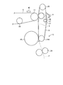
図1は、本発明の実施の一形態にかかるカラーデジタル複合機100の概略構成図である。図1に示すように、カラーデジタル複合機100は、画像読取装置であるスキャナ部200と、電子写真方式の画像印刷装置であるプリンタ部300とで構成されている。これらのスキャナ部200とプリンタ部300とによって、エンジン制御部500(図3参照)が構成されている。本実施の形態にかかるカラーデジタル複合機100は、操作部400(図3参照)のアプリケーション切り替えキーにより、ドキュメントボックス機能、複写機能、プリンタ機能、およびファクシミリ機能を順次に切り替えて選択することが可能となっている。ドキュメントボックス機能の選択時にはドキュメントボックスモードとなり、複写機能の選択時には複写モードとなり、プリンタ機能の選択時にはプリンタモードとなり、ファクシミリモードの選択時にはファクシミリモードとなる。
FIG. 1 is a schematic configuration diagram of a color digital multifunction peripheral 100 according to an embodiment of the present invention. As shown in FIG. 1, the color digital multifunction peripheral 100 includes a
本実施の形態のカラーデジタル複合機100における特徴的な機能を有しているプリンタ部300について詳述する。カラーデジタル複合機100のプリンタ部300は、図1に示すように、イエロー、マゼンタ、シアン(以下、Y、M、Cと略す)の3つの画像形成ユニット12Y、12M、12Cが、ループ状をなして略水平に延びる中間転写体としての中間転写ベルト6に沿ってベルト移動方向に直列に配置されたタンデム方式である。中間転写ベルト6は、駆動ローラ17、従動ローラ18、テンションローラ19、20により支持されている。従動ローラ18に対向して中間転写ベルト6の外側には、中間転写ベルト6上の残留トナーを除去するクリーニング手段7が設けられている。
The
加えて、カラーデジタル複合機100のプリンタ部300は、前記タンデム配列より転写紙(記録媒体)移動方向の上流位置に、ブラック(K)の画像形成ユニット12Kを独立して設けている。ブラック(K)の画像形成ユニット12Kは、ブラックの画像形成ユニット12Kのトナー像が転写紙に直接転写されるよう配置されている。より詳細には、ブラックの画像形成ユニット12Kは、中間転写ベルト6に対するY、M、C色の転写構成とは独立しており、そこで作成されたブラックトナー像は中間転写ベルト6とは異なる2次転写部15により転写紙に直接転写される。このような2次転写部15は、略水平に延びる中間転写ベルト6に対して略垂直に交差するように配置されていて、中間転写ベルト6上で重ね合わせられた複数色の画像と転写紙Pに転写された黒色の画像とが重ね合わされる転写紙Pの搬送経路上の位置に設けられる。さらに詳述すると、ブラックの画像形成ユニット12Kは、転写紙Pの略垂直搬送経路の近傍にこれに沿って配置されており、2次転写部15は略垂直搬送経路における定着装置10の上流側のスペースを利用して配置されている。
In addition, the
ここで、図2−1は2次転写部15の構成を概略的に示す模式図である。図2−1に示すように、2次転写部15は、直接転写体としての転写紙搬送ベルト8と、転写紙搬送ベルト8を支持する駆動ローラ25と、転写手段をかねる従動ローラ21Kと、テンションローラ27と、2次転写手段としての2次転写ローラ28と、転写紙搬送ベルト8上を清掃するクリーニング装置9とを主に備えている。2次転写ローラ28は中間転写ベルト6の駆動ローラ17に対向して配置されており、図示しない接離機構と、テンションローラ27によって転写紙搬送ベルト8の張力を保持することにより、中間転写ベルト6に対して図中実線で示すように近接可能、あるいは図中一点鎖線で示すように離間可能となっている。
Here, FIG. 2A is a schematic diagram schematically illustrating the configuration of the
なお、本実施の形態の2次転写部15においては、2次転写ローラ28を変位させる構成としたが、これに限るものではなく、従動ローラ21Kを支点として転写紙搬送ベルト8全体を変位させるようにしてもよい。
In the
従来より、モノクロ画像形成時に、ブラックを除く色の像担持体から中間転写ベルトを離間させる構成も知られている。この方式では中間転写ベルトのみ駆動してブラック以外の色の画像形成ユニットを駆動(空転)する必要はないが、中間転写ベルトを変位させるため張力変動の問題は避けられない。その点、2次転写ローラ28を変位させる構成、または、転写紙搬送ベルト8全体を変位させる構成にした場合、中間転写ベルト6に比べて周長が大幅に短い転写紙搬送ベルト8側が接離し、中間転写ベルト6は据え置き可能(転写紙搬送ベルト8と連動しない)となるため、中間転写ベルト6の張力変動がない。すなわち、位置合わせ数の多い中間転写ベルト6を転写紙搬送ベルト8に対して接離する構成とすることもできるが、この場合、位置合わせのための位置精度が経時的に低下する虞がある。これに対して、本実施の形態では、中間転写ベルト6をY、M、C色の各感光体1(1Y、1M、1C)に接したままの構成とすることができるため、中間転写ベルト6のローラ間の位置決め精度を高く設定できるので、ベルト寄りに対する余裕度が向上する。また、ベルト走行が安定化することにより、フルカラー時の位置ずれに対しても余裕度を向上させることができる。
Conventionally, a configuration is also known in which an intermediate transfer belt is separated from an image carrier of a color other than black when forming a monochrome image. In this method, it is not necessary to drive only the intermediate transfer belt and drive (idle) an image forming unit of a color other than black, but the problem of fluctuation in tension is unavoidable because the intermediate transfer belt is displaced. In this regard, when the configuration is such that the
また、図2−2に示すように、中間転写ベルト6を支持する駆動ローラ17を図示しない接離機構により変位させ、テンションローラ20によって中間転写ベルト6の張力を保持させて、中間転写ベルト6を転写紙搬送ベルト8に対して接離させる構成としてもよい。この場合、転写紙Pの搬送姿勢が変化することがないので、転写紙搬送ベルト8から定着装置10の間にかけて転写紙Pの挙動が不安定となることがない。このため、定着装置10から排出された後の転写紙Pにシワや画像の乱れが発生するのを防止することができる。さらに、2次転写部15の2次転写ローラ28および中間転写ベルト6を支持する駆動ローラ17の双方を移動させることによって、中間転写ベルト6と転写紙搬送ベルト8とを接離させる構成としてもよい。
Also, as shown in FIG. 2B, the driving
図1に戻り、各画像形成ユニット12Y、12M、12C、12Kは、プリンタ部300の本体に対して着脱可能なプロセスカートリッジとして構成されている。それぞれの画像形成ユニット12(12Y、12M、12C、12K)は、像担持体としての感光体1(1Y、1M、1C、1K)、帯電装置2(2Y、2M、2C、2K)、トナーを潜像に供給してトナー像を形成する現像装置3(3Y、3M、3C、3K)、クリーニング装置4(4Y、4M、4C、4K)等を備えている。各画像形成ユニット12Y、12M、12Cにおいては、各感光体1Y、1M、1Cが中間転写ベルト6の下側の展張面に接するように配置されている。また、中間転写ベルト6の内側には、各感光体1(1Y、1M、1C)に対向して1次転写手段としての1次転写ローラ21Y、21C、21Mが設けられている。
Returning to FIG. 1, each of the image forming units 12 </ b> Y, 12 </ b> M, 12 </ b> C, and 12 </ b> K is configured as a process cartridge that can be attached to and detached from the main body of the
また、カラーデジタル複合機100のプリンタ部300は、図示しないLDからレーザ光を発する各色の画像形成ユニット12(12Y、12M、12C、12K)に対応する露光装置5を備えている。スキャナ部200で読み取られた原稿、ファクシミリなどの受信データ、またはコンピュータから送信されるカラー画像情報は、イエロー、シアン、マゼンタ、ブラックの各色に色分解され、各色の版のデータが形成され、各色の画像形成ユニット12(12Y、12M、12C、12K)の露光装置5に送られる。露光装置5のLDから発せられるレーザ光は、各画像形成ユニット12(12Y、12M、12C、12K)の各感光体1(1Y、1M、1C、1K)上に静電潜像を形成する。
The
なお、本実施の形態では、クリーニング装置4、9としてブレードタイプのものを用いたが、本発明はこれに限定される趣旨ではなく、ファーブラシローラ、磁気ブラシクリーニング方式であっても良い。また、露光装置5についてもレーザ方式に限定するものではなく、LED方式などの方式であっても良い。
In the present embodiment, blade type devices are used as the
さらに、カラーデジタル複合機100のプリンタ部300は、中間転写ベルト6の幅方向左端、中央、右端に、図示しないLD走査のスキュー量等を検出するために、中間転写ベルト6上に形成された位置合わせ制御用パターン13(図7参照)を検出するパターン検出用センサ40を備えている。
Further, the
パターン検出用センサ40として反射型の光学式センサ(正反射光センサ)を使用した場合、中間転写ベルト6に光を照射し、中間転写ベルト6上に形成された位置合わせ制御用パターン13および中間転写ベルト6からの反射光をパターン検出用センサ40が検出して、位置ずれ量を計測するための情報を得る。
When a reflective optical sensor (regular reflection light sensor) is used as the
なお、パターン検出用センサ40として正反射光センサを適用するようにしたが、これに限るものではなく、位置合わせ制御用パターン13及び中間転写ベルト6により拡散された光を読み取る拡散光センサユニットを適用するようにしても良い。
Although a regular reflection light sensor is applied as the
位置合わせ制御機能は、基準色に対するスキュー、副走査レジストずれ、主走査レジストずれ、主走査倍率誤差の計測が可能である。なお、実際の読み取りは、位置合わせ制御用パターン13のエッジ部分を読み取っている。位置合わせ制御についての詳細は、後述する。 The alignment control function can measure skew with respect to the reference color, sub-scanning registration error, main-scanning registration error, and main-scanning magnification error. In actual reading, the edge portion of the alignment control pattern 13 is read. Details of the alignment control will be described later.
また、カラーデジタル複合機100のプリンタ部300の下部には、転写紙サイズが異なる給紙トレイ22、23が設けられており、各給紙トレイ22、23から図示しない給紙手段により給紙された転写紙Pは、図示しない搬送手段により搬送されてレジストローラ対24に達し、ここでスキューを修正された後にレジストローラ対24により所定のタイミングで、感光体1Kと転写紙搬送ベルト8の転写部位へ搬送される。
Further, under the
さらに、カラーデジタル複合機100のプリンタ部300は、中間転写ベルト6の上部に、トナーバンク32を備えている。トナーバンク32は、トナータンク32K、32Y、32C、32Mから構成され、これらのトナータンクはトナー補給パイプ33K、33Y、33C、33Mにより各現像装置3(3Y、3M、3C、3K)に接続されている。ブラックの画像形成ユニット12Kは、Y、M、C色の画像形成ユニット12(12Y、12M、12C)から独立して配置されているので、ブラックの作像工程にY、M、C色の転写トナーが混入することがない。このため、感光体1Kより回収されたトナーは、図示しないブラックトナー回収経路でブラックの現像装置3Kへ運ばれ、再利用される。なお、前記ブラックトナー回収経路の途中において、紙粉除去を行う装置や、トナーを廃棄する経路に切替え可能な装置を設けても良い。
Further, the
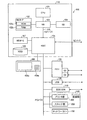
次に、カラーデジタル複合機100のハードウェア構成を説明する。図3は、カラーデジタル複合機100のハードウェア構成を示すブロック図である。図3に示すように、カラーデジタル複合機100は、コントローラ110とプリンタ部300およびスキャナ部200とをPCI(Peripheral Component Interconnect)バスで接続した構成となる。コントローラ110は、カラーデジタル複合機100全体の制御と描画、通信、操作部400からの入力を制御するコントローラである。なお、プリンタ部300またはスキャナ部200には、誤差拡散やガンマ変換などの画像処理部分が含まれる。操作部400は、スキャナ部200で読み取られた原稿の原稿画像情報等をLCD(Liquid Crystal Display)に表示するとともに操作者からの入力をタッチパネルを介して受け付ける操作表示部400aと、操作者からのキー入力を受け付けるキーボード部400bとを有している。
Next, the hardware configuration of the color digital multifunction peripheral 100 will be described. FIG. 3 is a block diagram illustrating a hardware configuration of the color digital multifunction peripheral 100. As shown in FIG. 3, the color digital multifunction peripheral 100 has a configuration in which a
コントローラ110は、コンピュータの主要部であるCPU(Central Processing Unit)101と、システムメモリ(MEM−P)102と、ノースブリッジ(NB)103と、サウスブリッジ(SB)104と、ASIC(Application Specific Integrated Circuit)106と、記憶部であるローカルメモリ(MEM−C)107と、記憶部であるハードディスクドライブ(HDD)108とを有し、NB103とASIC106との間をAGP(Accelerated Graphics Port)バス105で接続した構成となる。また、MEM−P102は、ROM(Read Only Memory)102aと、RAM(Random Access Memory)102bとをさらに有する。
The
CPU101は、カラーデジタル複合機100の全体制御を行うものであり、NB103、MEM−P102およびSB104からなるチップセットを有し、このチップセットを介して他の機器と接続される。
The
NB103は、CPU101とMEM−P102、SB104、AGPバス105とを接続するためのブリッジであり、MEM−P102に対する読み書きなどを制御するメモリコントローラと、PCIマスタおよびAGPターゲットとを有する。
The
MEM−P102は、プログラムやデータの格納用メモリ、プログラムやデータの展開用メモリ、プリンタの描画用メモリなどとして用いるシステムメモリであり、ROM102aとRAM102bとからなる。ROM102aは、CPU101の動作を制御するプログラムやデータの格納用メモリとして用いる読み出し専用のメモリであり、RAM102bは、プログラムやデータの展開用メモリ、プリンタの描画用メモリなどとして用いる書き込みおよび読み出し可能なメモリである。
The MEM-
SB104は、NB103とPCIデバイス、周辺デバイスとを接続するためのブリッジである。このSB104は、PCIバスを介してNB103と接続されており、このPCIバスには、ネットワークインタフェース(I/F)150なども接続される。
The
ASIC106は、画像処理用のハードウェア要素を有する画像処理用途向けのIC(Integrated Circuit)であり、AGPバス105、PCIバス、HDD108およびMEM−C107をそれぞれ接続するブリッジの役割を有する。このASIC106は、PCIターゲットおよびAGPマスタと、ASIC106の中核をなすアービタ(ARB)と、MEM−C107を制御するメモリコントローラと、ハードウェアロジックなどにより画像データの回転などを行う複数のDMAC(Direct Memory Access Controller)と、プリンタ部300やスキャナ部200との間でPCIバスを介したデータ転送を行うPCIユニットとからなる。このASIC106には、PCIバスを介してFCU(Fax Control Unit)120、USB(Universal Serial Bus)130、IEEE1394(the Institute of Electrical and Electronics Engineers 1394)インタフェース140が接続される。
The
MEM−C107は、コピー用画像バッファ、符号バッファとして用いるローカルメモリであり、HDD108は、画像データの蓄積、CPU101の動作を制御するプログラムの蓄積、フォントデータの蓄積、フォームの蓄積を行うためのストレージである。
The MEM-
AGPバス105は、グラフィック処理を高速化するために提案されたグラフィックスアクセラレータカード用のバスインタフェースであり、MEM−P102に高スループットで直接アクセスすることにより、グラフィックスアクセラレータカードを高速にするものである。
The AGP bus 105 is a bus interface for a graphics accelerator card proposed for speeding up graphics processing. The AGP bus 105 speeds up the graphics accelerator card by directly accessing the MEM-
なお、本実施の形態のカラーデジタル複合機100で実行されるプログラムは、ROM等に予め組み込まれて提供される。本実施の形態のカラーデジタル複合機100で実行されるプログラムは、インストール可能な形式又は実行可能な形式のファイルでCD−ROM、フレキシブルディスク(FD)、CD−R、DVD(Digital Versatile Disk)等のコンピュータで読み取り可能な記録媒体に記録して提供するように構成してもよい。
The program executed by the color digital multifunction peripheral 100 according to the present embodiment is provided by being incorporated in advance in a ROM or the like. The program executed in the color
さらに、本実施の形態のカラーデジタル複合機100で実行されるプログラムを、インターネット等のネットワークに接続されたコンピュータ上に格納し、ネットワーク経由でダウンロードさせることにより提供するように構成してもよい。また、本実施の形態のカラーデジタル複合機100で実行されるプログラムをインターネット等のネットワーク経由で提供または配布するように構成してもよい。
Furthermore, the program executed by the color
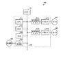
図4は、プリンタ部300のハードウェア構成を示すブロック図である。図4に示すように、プリンタ部300の制御系は、CPU301、RAM302、ROM303、I/O制御部304、転写駆動モータI/F306a、ドライバ307a、転写駆動モータI/F306b、ドライバ307bから構成されている。
FIG. 4 is a block diagram illustrating a hardware configuration of the
上記CPU301は、コントローラ110から入力される画像データの受信及び制御コマンドの送受信制御をはじめ、プリンタ部300全体の制御を行っている。
The
またワーク用として用いるRAM302及びプログラムを記憶するROM303、I/O制御部304は、バス309を介して相互に接続され、CPU301からの指示によりデータのリード/ライト処理及び接離機構などの各負荷305を駆動するモータ、クラッチ、ソレノイド、センサなど各種の動作を実行する。
A
転写駆動モータI/F306aは、CPU301からの駆動指令により、ドライバ307aに対して駆動パルス信号の駆動周波数を指令する指令信号を出力する。この周波数に応じて転写駆動モータM1が回転駆動される。この回転駆動によって、図2に示す駆動ローラ17が回転駆動される。同じく、転写駆動モータI/F306bは、CPU301からの駆動指令により、ドライバ307bに対して駆動パルス信号の駆動周波数を指令する指令信号を出力する。この周波数に応じて転写駆動モータM2が回転駆動される。この回転駆動によって、図2に示す駆動ローラ25が回転駆動される。
In response to a drive command from the
また、RAM302はROM303に記憶されているプログラムを実行する際のワークエリアとして使用される。このRAM302は揮発性メモリのため、振幅・位相値など次のベルト駆動で使用するパラメータに関しては、図示しないEEPROM(Electrically Erasable Programmable Read Only Memory)などの不揮発性メモリに記憶しておき、電源オン時もしくは駆動モータ17の駆動時にsin関数もしくは近似式を用いて、ベルト一周期分のデータをRAM302上に展開する。
The
本実施の形態のプリンタ部300で実行されるプログラムは、後述する各部(印刷制御部51、位置合わせ制御部52、間接転写制御部53、直接転写制御部54、2次転写制御部55など(図5参照))を含むモジュール構成となっており、実際のハードウェアとしてはCPU301が上記ROM303からプログラムを読み出して実行することにより上記各部が主記憶装置上にロードされ、印刷制御部51、位置合わせ制御部52、間接転写制御部53、直接転写制御部54、2次転写制御部55などが主記憶装置上に生成されるようになっている。
A program executed by the
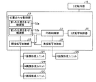
図5は、プリンタ部300の機能構成を示すブロック図である。プリンタ部300は、印刷制御部51と、位置合わせ制御部52と、間接転写制御部53と、直接転写制御部54と、2次転写制御部55と、を主に備えている。
FIG. 5 is a block diagram illustrating a functional configuration of the
印刷制御部51は、フルカラー印刷やモノクロ印刷等および位置合わせ制御処理を実行するために、システム全体、即ち位置合わせ制御部52、間接転写制御部53、直接転写制御部54、2次転写制御部55等を制御する。印刷制御部51が行う制御処理については、図11〜図14を用いて後述する。
The
位置合わせ制御部52は、画像形成ユニット12Y、12M、12K、12Cが形成する各画像の位置合わせ制御処理を行うために、間接転写制御部53、直接転写制御部54、2次転写制御部55等を制御する。また、位置合わせ制御部52は、第1の位置合わせ制御部52aと、第2の位置合わせ制御部52bとを備えている。
The
第1の位置合わせ制御部52aは、概略的には、直接転写側の画像形成ユニット12Kが形成するK色を基準色として、間接転写側の画像形成ユニット12Cが形成するC色の画像についてK色の画像に対する位置合わせである、第1の位置合わせ制御処理を行う。
The first
第2の位置合わせ制御部52bは、概略的には、第1の位置合わせ制御において位置合わせが行われたC色を基準色として、M色、Y色の画像についてC色の画像に対する位置合わせである、第2の位置合わせ制御処理を行う。
The second
即ち、本実施の形態のカラーデジタル複合機100は、図6に示すように、第1の位置合わせ制御部52aによって直接転写側のK色の画像と間接転写側のC色の画像との間の位置合わせを行う第1の位置合わせを行い、第2の位置合わせ制御部52bによって間接転写側のY、M、C色間の位置合わせを行う第2の位置合わせと行うことにより、全色の位置合わせを2段階に分けて行うことを特徴としている。これにより、直接転写方式で画像形成を行うK色の画像と、間接転写方式で画像形成を行うY、M、C色の画像とに対して全色の位置合わせを行うことが可能となる。
That is, as shown in FIG. 6, the color digital multi-function peripheral 100 according to the present embodiment uses the first
間接転写制御部53は、印刷制御部51の制御によるフルカラー印刷時に、Y、M、C色の画像形成ユニット12Y、12M、12Cと中間転写ベルト6を制御し、転写紙Pに転写するための画像を各感光体1Y、1M、1C上に形成する。各感光体1Y、1M、1Cに形成されたY、M、C色のトナー画像は、間接転写方式によって中間転写ベルト6上に重ね合わせられる。
The indirect
また、間接転写制御部53は、第1の位置合わせ制御部52aの制御による第1の位置合わせ制御処理時に、画像形成ユニット12Cと中間転写ベルト6とを制御し、位置合わせ制御用パターン13C(図7参照)を中間転写ベルト6上に形成する。
Further, the indirect
また、間接転写制御部53は、第2の位置合わせ制御部52bの制御による第2の位置合わせ制御処理時に、Y、M、C色の画像形成ユニット12Y、12M、12Cと中間転写ベルト6とを制御し、位置合わせ制御処理のための位置合わせ制御用パターン13Y、13M、13C(図10参照)を中間転写ベルト6上に形成する。
Further, the indirect
直接転写制御部54は、印刷制御部51の制御によるフルカラー印刷およびモノクロ印刷時に、K色の画像形成ユニット12Kを制御して、転写紙Pに転写するための画像を感光体1Kに形成する。感光体1Kに形成されたK色のトナー画像は、直接転写方式によって、感光体1Kと転写手段である従動ローラ21Kが当接する地点で転写紙Pに転写され、印刷される。
The direct transfer control unit 54 controls the K-color
また、直接転写制御部54は、第1の位置合わせ制御部52aの制御による第1の位置合わせ制御処理時に、画像形成ユニット12Kと、転写紙搬送ベルト8とを制御し、位置合わせ制御用パターン13K(図8参照)を転写紙搬送ベルト8上に形成する。
Further, the direct transfer control unit 54 controls the
2次転写制御部55は、印刷制御部51の制御によるフルカラー印刷時および第1の位置合わせ制御部52aの制御による第1の位置合わせ制御処理時に、2次転写ローラ28を動作させて、中間転写ベルト6に接近させる。
The secondary
また、2次転写制御部55は、印刷制御部51の制御によるモノクロ印刷時および第2の位置合わせ制御部52bの制御による第2の位置合わせ制御処理時に、転写紙Pまたは転写紙搬送ベルト9にY、M、C色のトナー画像を転写する必要がないため、2次転写ローラ28を動作させて中間転写ベルト6から離間させる。
The secondary
次に、上述したような第1の位置合わせ制御処理における第1の位置合わせ制御部52aの制御について、図7〜図9を用いて詳述する。
Next, the control of the first
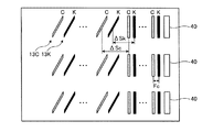
まず、第1の位置合わせ制御部52aは、間接転写制御部53および画像形成ユニット12Cによって中間転写ベルト6上に位置合わせ制御用パターン13Cを形成させる。図7は、感光体1Cによって中間転写ベルト6上に形成される位置合わせ制御用パターン13Cの一例を示す平面図である。
First, the first
図7に示すように、位置合わせ制御用パターン13Cは、平行線のパターンと、斜め線のパターンを副走査方向に一定間隔に配置したものである。このような位置合わせ制御用パターン13Cは、中間転写ベルト6の搬送方向に沿って繰り返し形成される。位置合わせ制御用パターン13は、サンプル数を多くして誤差による影響を減らすために、図7に示すようにパターン検出用センサ40の位置にあわせて複数出力される。
As shown in FIG. 7, the
また、第1の位置合わせ制御部52aは、直接転写制御部54および画像形成ユニット12Kによって転写紙搬送ベルト8上に位置合わせ制御用パターン13Kを形成させる。図8は、感光体1Kによって転写紙搬送ベルト8上に形成される位置合わせ制御用パターン13Kの一例を示す平面図である。位置合わせ制御用パターン13Kは、位置合わせ制御用パターン13Cと同様のパターンから成り、転写紙搬送ベルト8の搬送方向に沿って繰り返し形成される。
Further, the first
次に、第1の位置合わせ制御部52aは、2次転写制御部55が中間転写ベルト6と転写紙搬送ベルト8とを近接させることにより、転写紙搬送ベルト8上に形成された位置合わせ制御用パターン13Kを中間転写ベルト6上に転写し、中間転写ベルト6上に形成された位置合わせ制御用パターン13C上に重ね合わせる。図9は、第1の位置合わせ制御処理の際に、中間転写ベルト6上に形成された位置合わせ制御用パターン13Cおよび13Kを示す図である。
Next, the first
ここで、第1の位置合わせ制御部52aは、間接転写側の画像形成ユニット12Y、12M、12Cのうち、中間転写ベルト6の搬送方向において最も2次転写部15に近い画像形成ユニット12Cが形成するC色の画像を用いて第1の位置合わせ制御処理を行うことを特徴とする。
Here, the first
これにより、C色の位置合わせ制御用パターン13CとK色の位置合わせ制御用パターン13Kとを合成する場合、中間転写ベルト6上にC色の位置合わせ制御用パターン13Cが形成されてから、転写紙搬送ベルト8上の位置合わせ制御用パターン13Kが中間転写ベルト6上に転写されるまでに、中間転写ベルト6の移動距離が最短となる。これにより、位置合わせ制御用パターン13K、13Cを合成するまでの所要時間も最短とすることができ、位置合わせに必要な時間を短縮することができるという効果を奏する。
Thus, when the C color
次に、第1の位置合わせ制御部52aは、上述のようにして中間転写ベルト6上に形成された位置合わせ制御用パターン13Kおよび13Cの合成パターンを、パターン検出用センサ40により位置合わせ制御用パターン13Kおよび13Cを検出する。さらに、第1の位置合わせ制御部52aは、検出した位置合わせ制御用パターン13Kおよび13Cにより主走査ずれ量および副走査ずれ量の演算を行う。
Next, the first
まず、第1の位置合わせ制御部52aは、位置合わせ制御用パターン13K、13Cに対し、縦線がパターン検出用センサ40によって検出されてから縦線と同色で形成された斜め線が検出されるまでの時間をCPU101のタイマ機能で計測し、計測した時間から縦線と斜め線との間隔ΔSkおよびΔSc(図9参照)を算出する。第1の位置合わせ制御部52aは、算出した間隔ΔSkおよびΔScを予め記憶されている各々の基準値と比較することで、主走査方向の位置ずれ量および補正値を算出する。
First, the first
一方、第1の位置合わせ制御部52aは、位置合わせ制御用パターン13K、13Cに対し、基準色であるK色の位置合わせ制御用パターン13Kがパターン検出用センサ40によって検出されてからC色の位置合わせ制御用パターン13Cが検出されるまでの時間をCPU101のタイマ機能で計測し、計測した時間から位置合わせ制御用パターン13Kおよび13Cとの間隔ΔFcを算出する。第1の位置合わせ制御部52aは、算出した間隔ΔFcを予め記憶されている基準値と比較することで、副走査方向の位置ずれ量および補正値を算出する。
On the other hand, the first
第1の位置合わせ制御部52aは、この補正値に基づいて主副走査位置の調整やスキュー調整を行い、画像形成ユニット12K、12Cで形成される画像の位置を補正する。
The first
次に、第2の位置合わせ制御処理において第2の位置合わせ制御部52bが行う制御処理について詳述する。
Next, the control process performed by the second
第2の位置合わせ制御部52bは、2次転写制御部55によって中間転写ベルト6と転写紙搬送ベルト8とを離間させ、間接転写制御部53および画像形成ユニット12Y、12M、12Cによって中間転写ベルト6上に位置合わせ制御用パターン13Y、13M、13Cを形成させる。図10は、第2の位置合わせ制御処理の際に、感光体1Y、1M、1Cによって中間転写ベルト6上に形成される位置合わせ制御用パターン13Y、13M、13Cを示す図である。
The second
図10に示すように、位置合わせ制御用パターン13Y、13M、13Cは、3本の並行なパターンと、3本の斜め線のパターンを副走査方向に一定間隔に配置したものである。位置合わせ制御用パターン13Y、13M、13Cは、中間転写ベルト6の搬送方向に沿って繰り返し形成される。
As shown in FIG. 10, the
次に、第2の位置合わせ制御部52bは、このように中間転写ベルト6上に形成された位置合わせ制御用パターン13Y、13M、13C(図10参照)を、パターン検出用センサ40により検出し、主走査ずれ量および副走査ずれ量の演算を行う。
Next, the second
先ず、第2の位置合わせ制御部52bは、位置合わせ制御用パターン13Y、13M、13Cに対し、縦線がパターン検出用センサ40によって検出されてから縦線と同色で形成された斜め線が検出されるまでの時間をCPU101のタイマ機能で計測し、計測した時間から縦線と斜め線との間隔ΔSy、ΔSm、ΔSc(図10参照)を算出する。第2の位置合わせ制御部52bは、算出した間隔ΔSy、ΔSm、ΔScを予め記憶されている各々の基準値と比較することで、主走査方向の位置ずれ量および補正値を算出する。
First, the second
一方、第2の位置合わせ制御部52bは、第1の位置合わせ制御において位置合わせが行われたCを基準色とし、位置合わせ制御用パターン13Cがパターン検出用センサ40によって検出されてからY、Mの位置合わせ制御用パターン13Y、13Mが検出されるまでの時間をCPU101のタイマ機能で計測し、計測した時間から位置合わせ制御用パターン13Y、13Mと位置合わせ制御用パターン13Cとの間隔ΔFy、ΔFmを算出する。第2の位置合わせ制御部52bは、算出した間隔ΔFy、ΔFmを各々の間隔の基準値と比較することで、副走査方向の位置ずれ量および補正値を算出する。
On the other hand, the second
第2の位置合わせ制御部52bは、この補正値に基づいて主副走査位置の調整やスキュー調整を行い、画像形成ユニット12Y、12M、12Cで形成される画像の位置を補正する。
The second
次に、フルカラー印刷時、第1の位置合わせ制御時および第2の位置合わせ制御時における、印刷制御部51および位置合わせ制御部52による制御について図11〜図14を用いて説明する。
Next, control by the
まず、フルカラー印刷時における印刷制御部51による制御について説明する。図11は、フルカラー印刷時の各感光体1と2次転写ローラ28の動作を説明する図である。
First, control by the
フルカラー印刷時に、印刷制御部51は、2次転写制御部55によって2次転写ローラ28を中間転写ベルト6へ接近させ、間接転写制御部53に画像形成ユニット12Y、12M、12Cおよび中間転写ベルト6を制御させてY、M、C色の印刷処理を実行させ、これと並行して直接転写制御部54に画像形成ユニット12Kおよび転写紙搬送ベルト8を制御させ、K色の印刷処理を実行させる。
During full-color printing, the
なお、図11に示す2次転写ローラ28の当接とは、中間転写ベルト6へ2次転写ローラ28が接近しており、中間転写ベルト6に形成された画像は転写紙搬送ベルト8または転写紙搬送ベルト8により搬送されている搬送紙Pに2次転写することが可能であることを表す。
The contact of the
すなわち、印刷制御部51は、帯電装置2(2Y、2M、2C、2K)によって均一に帯電された感光体1(1Y、1M、1C、1K)は、露光装置5からの色別の露光光により画像部を露光し、現像装置3(3Y、3M、3C、3K)によってトナー像を作らせる。その後、印刷制御部51は、感光体1Y、1M、1C上に作られたカラートナー像を、タイミングを合わせて中間転写ベルト6に転写させ、色重ねされたトナー像を形成させる。一方、印刷制御部51は、感光体1K上に作られたブラックトナー像を、転写搬送ベルトとしての転写紙搬送ベルト8によって搬送される転写紙Pに直接転写させ、その後、中間転写ベルト6上に色重ねされたY、M、Cトナー像を転写紙P上に転写させる。故に、転写紙搬送ベルト8はブラックトナー像の転写部では直接転写ベルトとして機能し、中間転写ベルト6上のY、M、Cトナー像の転写部では2次転写ベルトとして機能する。
That is, the
その後、印刷制御部51は、ブラックトナー像とY、M、Cトナー像を重ねて転写された転写紙Pを、定着装置10によりトナー像を定着させてフルカラー画像の印刷処理を完了する。印刷制御部51は、定着を終えた転写紙Pを搬送経路R1(図1参照)に搬送させ、排紙ローラ対30により排紙トレイ31にフェイスダウン状態で排出させてスタックさせる。両面モードの場合には、印刷制御部51は、図示しない切替え爪により搬送経路R2へ案内させ、両面ユニット34で反転された後にレジストローラ対24へ搬送させて片面コピーと同様の排紙経路を辿らせる。
Thereafter, the
次に、モノクロ印刷時における印刷制御部51による制御について説明する。図12は、モノクロ印刷時の各感光体1と2次転写ローラ28の動作を説明する図である。
Next, control by the
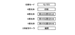
モノクロ印刷時に、印刷制御部51は、2次転写制御部55によって2次転写ローラ28と中間転写ベルト6とを離間させ、間接転写制御部53によるY、M、C色の印刷処理は停止させて、直接印刷制御部54に画像形成ユニット12Kおよび転写紙搬送ベルト9を制御させてK色の印刷処理を実行させる。
During monochrome printing, the
すなわち、印刷制御部51は、ブラックの画像データに基づいて露光装置5により、感光体1K上の画像部を露光させ、現像装置3Kによってトナー像を作らせる。印刷制御部51は、作成されたブラックトナー像を転写紙搬送ベルト8によって搬送される転写紙P上に直接転写させ、定着装置10により定着させ、モノクロ画像の印刷処理を完了する。
That is, the
モノクロ画像形成時、中間転写ベルト6と転写紙搬送ベルト8の接触部は、図2−1に示すように離間されており、Y、M、C色の各画像形成ユニット12(12Y、12M、12C)、及び中間転写ベルト6は動作しない。これにより、Y、M、C色の各画像形成ユニット12(12Y、12M、12C)、及び中間転写ベルト6の長寿命化を図ることができるという効果を奏する。
When a monochrome image is formed, the contact portion between the
なお、図10に示す2次転写ローラ28の離間とは、中間転写ベルト6から2次転写ローラ28が離れていることを表す。
The separation of the
次に、第1の位置合わせ制御時における第1の位置合わせ制御部52aによる制御について説明する。図13は、第1の位置合わせ制御時における各感光体1と2次転写ローラ28の動作を説明する図である。
Next, the control performed by the first
図13に示すように、第1の位置合わせ制御部52aは、位置合わせ制御部52に、感光体1Cを動作させてC色の位置合わせ制御用パターン13C(図7参照)を中間転写ベルト6上に形成させ、これと並行して、感光体1Kを動作させてK色の位置合わせ制御用パターン13K(図8参照)を転写紙搬送ベルト8上に形成させる。さらに、第1の位置合わせ制御部52aは、2次転写制御部55に2次転写ローラ28と中間転写ベルト6とを当接させて、転写紙搬送ベルト8上の位置合わせ制御用パターン13Kを中間転写ベルト6上に転写する。さらに、第1の位置合わせ制御部52aは、中間転写ベルト6上で合成された位置合わせ制御用パターン13Kおよび13Cをパターン検出センサ40で検出し、K色とC色の位置ずれ量を演算することにより第1の位置合わせ制御処理を実行する。このとき、第1の位置合わせ制御に用いないM、Yの感光体1M、1Yは空駆動を行う。
As shown in FIG. 13, the first
次に、第2の位置合わせ制御時における第2の位置合わせ制御部52bによる制御について説明する。図14は、第1の位置合わせ制御時における各感光体1と2次転写ローラ28の動作を説明する図である。
Next, the control by the second
図14に示すように、第2の位置合わせ制御部52bは、間接転写制御部53に感光体1Y、1M、1Cを動作させて、Y、M、C色の位置合わせ制御用パターン13Y、13M、13C(図10参照)を中間転写ベルト6上に形成させる。さらに、第2の位置合わせ制御部52bは、中間転写ベルト7上に合成されたY、M、C色の位置合わせ制御パターン13Y、13M、13Cをパターン検出用センサ40で検出し、第1の位置合わせ制御処理時に位置合わせが行われたCを基準色としてY、Mの位置ずれ量を演算することにより第2の位置合わせ制御を行う。このとき、第2の位置合わせ制御部52bは、2次転写制御部55に2次転写ローラ28と中間転写ベルト6とを離間させ、直接転写制御部54による感光体1Kの動作を停止させる。
As shown in FIG. 14, the second
次に、第2の位置合わせ制御時と並行してモノクロ印刷を行う場合の印刷制御部51および第2の位置合わせ制御部52bによる制御について説明する。図15は、第2の位置合わせ制御時と並行してモノクロ印刷を行う場合の各感光体1と2次転写ローラ28の動作を説明する図である。
Next, control by the
図15に示すように、印刷制御部51は、K色の画像のみを転写紙Pに転写するため、2次転写部15の2次転写ローラ28を中間転写ベルトから離間させ、感光体1Kのみに印刷動作を実行させる。一方、印刷制御部51は、第2の位置合わせ制御部52bに第2の位置合わせ制御を開始させる。即ち、第2の位置合わせ制御部52bは、間接転写制御部53に感光体1Y、1M、1Cを動作させて、Y、M、C色の位置合わせ制御用パターン13Y、13M、13C(図10参照)を中間転写ベルト6上に形成させ、上述のように第2の位置合わせ制御処理を行う。
As shown in FIG. 15, in order to transfer only the K-color image onto the transfer paper P, the
このようにして、印刷制御部51は、モノクロ印刷時におけるK色の画像形成ユニット12Kの印刷動作と、Y、M、C色の画像形成ユニット12(12Y、12M、12C)の位置合わせ制御とを並行動作させることが可能となり、印刷のダウンタイムを増加させることなく、位置合わせ制御処理を行うことが可能となる。
In this way, the
また、中間転写ベルト6と転写紙搬送ベルト8の接触部を離間させることによって、位置合わせ制御用パターン13Y、13M、13Cの形成に用いるY、M、C色のトナーが転写紙搬送ベルト8に付着し、同時にモノクロ印刷する場合に転写紙Pの裏にY、M、C色のトナーが付着してしまい裏汚れになってしまうことを防止することができる。
Further, by separating the contact portion between the
続いて、印刷制御部51によるシステム制御の状態遷移について図16〜図22を用いて説明する。
Next, system control state transition by the
図16は、印刷待機状態および第1の位置合わせから、モノクロ印刷および第2の位置合わせに遷移し、そしてフルカラー印刷に遷移する、第1のシステム制御例を示す模式図である。 FIG. 16 is a schematic diagram illustrating a first system control example in which a transition is made from monochrome printing and second alignment to full-color printing from the print standby state and the first alignment.
図16に示すように、印刷待機状態および第1の位置合わせの次にモノクロ印刷および第2の位置合わせに遷移する場合、第1の位置合わせが終了すると、印刷制御部51は、2次転写制御部55に2次転写ローラ28と中間転写ベルト6とを離間させる。そして、第2の位置合わせを開始するよう第2の位置合わせ制御部52bに指示を出す。第2の位置合わせ制御部52bはこの指示を受けて、間接転写制御部53を制御し、感光体1Y、1M、1Cを制御して位置合わせ制御用パターン13Y、13M、13Cを中間転写ベルト6上に形成させる。第2の位置合わせ制御部52bは、前述したように、位置合わせ制御用パターン13Y、13M、13Cをパターン検出用センサ40により検出して補正値を算出し、この補正値に基づいて画像の形成位置を補正する。
As shown in FIG. 16, in the case of transition to monochrome printing and second alignment after the print standby state and first alignment, when the first alignment is completed, the
そして、印刷制御部51は、第2の位置合わせ制御部52bに指示を出すことと並行して、直接転写制御部54には画像出力を指示し、モノクロ印刷を開始させる。印刷制御部51は、モノクロ印刷が終了し、さらに第2の位置合わせ制御処理が終了した場合に、受付けたフルカラー印刷のジョブを開始する。即ち、印刷制御部51は、2次転写制御部55に2次転写ローラ28と中間転写ベルト6とを当接させて、間接転写制御部53および直接転写制御部54に画像出力を指示し、フルカラー印刷を開始させる。
In parallel with issuing an instruction to the second
このように、モノクロ印刷の次にフルカラー印刷を行う場合、第2の位置合わせとモノクロ印刷を並行して行えるため、フルカラー印刷の直前にY、M、C、K全色における位置合わせの実行が可能となり、印刷の待機時間を大幅に増加させることなく、フルカラー印刷時に経時などによる色ずれ量を軽減できる。 As described above, when full color printing is performed after monochrome printing, the second alignment and monochrome printing can be performed in parallel. Therefore, alignment for all colors Y, M, C, and K is performed immediately before full color printing. This makes it possible to reduce the amount of color misregistration due to aging during full color printing without significantly increasing the waiting time for printing.
図17は、印刷待機状態および第1の位置合わせからモノクロ印刷および第2の位置合わせを行った後に、印刷処理の停止に遷移する、第2のシステム制御例を示す模式図である。 FIG. 17 is a schematic diagram illustrating a second system control example in which the monochrome printing and the second alignment are performed from the print standby state and the first alignment, and then the print processing is stopped.
待機状態からモノクロ印刷を行う場合、印刷制御部51は、2次転写ローラ28と中間転写ベルト6を当接させ、第1の位置合わせ制御部52aに第1の位置合わせ制御処理を開始するよう指示する。第1の位置合わせ制御部52aは、直接転写制御部54および感光体1Kに位置合わせ制御用パターン13Kの出力を指示し、これと並行して、間接転写制御部53および感光体1Cに位置合わせ制御用パターン12Cの出力を指示する。さらに第1の位置合わせ制御部52aは、2次転写制御部55により近接制御を行って、K色の位置合わせ制御用パターン13Kを中間転写ベルト6上に転写する。第1の位置合わせ制御部52aは、パターン検出用センサ40によって中間転写ベルト6上に形成されたK色とC色の合成パターン画像を検出し、上述したように補正値を演算し、この補正値に基づいて画像形成ユニット12Cが形成する画像の位置を補正する。
When performing monochrome printing from the standby state, the
第1の位置合わせが終了すると、印刷制御部51は2次転写制御部55により2次転写ローラ28と中間転写ベルト6を離間させる。そして、第2の位置合わせ制御部52bは第2の位置合わせを実施する為に、感光体1Y、1M、1Cに位置合わせ制御用パターン13Y、13M、13Cの出力を指示する。第2の位置合わせ制御部52bは、パターン検出用センサ40によって中間転写ベルト6上に形成された位置合わせ制御用パターン13Y、13M、13Cを検出し、補正値を演算し、この補正値に基づいて画像形成ユニット1Y、1M、1Cが形成する画像の位置を補正する。また、第2の位置合わせと並行して、印刷制御部51は直接転写制御部54には画像出力を指示し、モノクロ印刷を開始する。モノクロ印刷と第2の位置合わせが終了すると、印刷制御部51は2次転写制御部55に2次転写ローラ28と中間転写ベルト6とを離間させ、画像形成ユニット12Kを停止させ、さらに、間接転写制御部53にフルカラー印刷を実行させる。
When the first alignment is completed, the
このように、第2のシステム制御例においては、モノクロ印刷を行う場合、第2の位置合わせとモノクロ印刷を並行して行えるため、モノクロ印刷に付随して、経時などによる位置ずれ量を軽減できることが可能となる。 As described above, in the second system control example, when monochrome printing is performed, the second alignment and monochrome printing can be performed in parallel, so that the amount of misalignment due to aging can be reduced accompanying monochrome printing. Is possible.
図18は、モノクロ印刷および第2の位置合わせから印刷待機状態および第1の位置合わせを行った後にフルカラー印刷に遷移する、第3のシステム制御例を示す模式図である。第1、第2のシステム制御例において、印刷制御部51は、先に第1の位置合わせを行わせて、その後第2の位置合わせを行わせたが、第3のシステム制御例において、印刷制御部51は、先に第2の位置合わせを行わせ、その後第1の位置合わせを行わせる。
FIG. 18 is a schematic diagram illustrating a third system control example that transitions from monochrome printing and second alignment to full-color printing after performing the print standby state and the first alignment. In the first and second system control examples, the
図18に示すように、印刷制御部51は先ずモノクロ印刷と並行して、第2の位置合わせ制御部52bにより第2の位置合わせを実行させる。モノクロ印刷中に第2の位置合わせを実施する為に、第2の位置合わせ制御部52bは、間接転写制御部53および感光体1Y、1M、1Cによって位置合わせ制御用パターン13Y、13M、13Cを出力させる。第2の位置合わせ制御部52bは、パターン検出用センサ40によって中間転写ベルト6上に形成された位置合わせ制御用パターン13Y、13M、13Cを検出し、Y、M、C色間の色ずれ量を検出して補正値を演算する。第2の位置合わせ制御部52bは、この補正値に基づいて画像形成ユニット12Y、12M、12Cが形成する画像の位置を補正する。
As shown in FIG. 18, the
モノクロ印刷と第2の位置合わせが終了すると、印刷制御部51は、第1の位置合わせを行う為に、2次転写制御部55に2次転写ローラ28と中間転写ベルト6を当接させ、第1の位置合わせ制御部52aに第1の位置合わせ制御を指示する。第1の位置合わせ制御部52aは、直接転写制御部54および感光体1Kに位置合わせ制御用パターン13Kの出力を指示し、これと並行して、間接転写制御部53および感光体1Cに位置合わせ制御用パターン13Cの出力を指示する。そして、第1の位置合わせ制御部52aは、2次転写制御部55によってK色の位置合わせ制御用パターン13Kを中間転写ベルト6上に転写させる。第1の位置合わせ制御部52aは、パターン検出用センサ40によって中間転写ベルト6上に形成されたK色とC色の合成パターン画像を検出し、K色とC色間の位置ずれ量を検出して、補正値を演算する。
When the monochrome printing and the second alignment are completed, the
この場合、Y、M、C色間の位置合わせは終了しており、Y、M、C色間については位置ずれが無い状態となる。従って、ここではK色に対してC色基準で補正処理を行うことになる。第2の位置合わせ制御部52bは、この補正値に基づいて画像形成ユニット12Kが形成する画像の位置を補正する。第1の位置合わせが終了した場合、印刷制御部51は続いてフルカラー印刷に移行する。
In this case, the alignment between the Y, M, and C colors is completed, and there is no misalignment between the Y, M, and C colors. Therefore, here, correction processing is performed on the K color on the basis of the C color. The second
このように、モノクロ印刷の次にフルカラー印刷を行う場合、第2の位置合わせとモノクロ印刷を並行して行えるため、フルカラー印刷の直前にY、M、C、K全色間の位置合わせが可能となり、印刷の待機時間を大幅に増加させることなく、フルカラー印刷時に経時などによる色ずれ量を軽減できる。 In this way, when full color printing is performed after monochrome printing, the second alignment and monochrome printing can be performed in parallel, so alignment between all colors Y, M, C, and K is possible immediately before full color printing. Therefore, the amount of color misregistration due to aging during full color printing can be reduced without significantly increasing the waiting time for printing.
図19は、フルカラー印刷が終了した場合に、第1の位置合わせおよび第2の位置合わせに遷移する、第4のシステム制御例を示す模式図である。 FIG. 19 is a schematic diagram illustrating a fourth system control example that transitions to the first alignment and the second alignment when full-color printing is completed.
フルカラー印刷が終了した場合、印刷制御部51は引き続き2次転写ローラ28と中間転写ベルト6を当接させておく。第1の位置合わせ制御部52aは、直接転写制御部54および感光体1Kに位置合わせ制御用パターン13Kの出力を指示し、これと並行して、間接転写制御部53および感光体1Cに位置合わせ制御用パターン13Cの出力を指示する。さらに、第1の位置合わせ制御部52aは、2次転写制御部55に近接制御を行わせて、K色の位置合わせ制御用パターン13Kを中間転写ベルト6上に転写する。第1の位置合わせ制御部52aは、パターン検出用センサ40によって中間転写ベルト6上のK色とC色の合成パターン画像を検出し、K色とC色間の位置ずれ量を検出して、位置合わせの為の補正値を演算する。第1の位置合わせ制御部52aは、この補正値に基づいて画像形成ユニット12Cが形成する画像の位置を補正する。
When the full color printing is finished, the
第1の位置合わせが終了すると、印刷制御部51は2次転写制御部55によって2次転写ローラ28と中間転写ベルト6を離間させ、感光体1Kを停止させる。第2の位置合わせ制御部52bは第2の位置合わせを実施する為に、間接転写制御部53および感光体1Y、1M、1Cに位置合わせ制御用パターン13Y、13M、13Cの出力を指示する。第2の位置合わせ制御部52bは、パターン検出用センサ40によって中間転写ベルト6上に形成された位置合わせ制御用パターン13Y、13M、13Cを検出し、Y、M、C色間の位置ずれ量を検出して、位置合わせのための補正値を演算する。第2の位置合わせ制御部52bは、この補正値に基づいて画像形成ユニット12Y、12M、12Cが形成する画像の位置を補正する。そして、第2の位置合わせが終了すると、印刷制御部51はプリンタ部300を停止させる。
When the first alignment is completed, the
このように、フルカラー印刷の終了時に位置合わせを行なうのと並行して、K色の感光体1Kを早めに停止させることができるので、K色の感光体1Kの寿命低下を低減することができる。
As described above, since the K-color
図20は、フルカラー印刷が終了した場合に、第1の位置合わせ制御を行い、モノクロ印刷および第2の位置合わせを行った後に停止する、第5のシステム制御例を示す模式図である。 FIG. 20 is a schematic diagram illustrating a fifth system control example in which the first alignment control is performed when monochrome printing and the second alignment are performed when full-color printing is completed.
印刷制御部51は、フルカラー印刷が終了した場合に、間接転写制御部53は印刷を行わない待機状態に移行させ、第1の位置合わせ制御部52aに第1の位置合わせ制御を指示する。具体的には、第1の位置合わせ制御部52aは、直接転写制御部54および感光体1Kに位置合わせ制御用パターン13Kの出力を指示し、これと並行して、間接転写制御部53および感光体1Cに位置合わせ制御用パターン13Cの出力を指示する。さらに、第1の位置合わせ制御部52aは、2次転写制御部55によってK色の位置合わせ制御用パターン13Kを中間転写ベルト6上に転写させる。第1の位置合わせ制御部52aはパターン検出用センサ40によって中間転写ベルト6上に形成されたK色とC色の合成パターン画像を検出し、K色とC色間の位置ずれ量を検出し、位置合わせの為の補正値を演算する。第1の位置合わせ制御部52aは、この補正値に基づいて画像形成ユニット12Cが形成する画像の位置を補正する。
When the full color printing is completed, the
第1の位置合わせが終了すると、2次転写制御部55は2次転写ローラ28と中間転写ベルト6を離間させる。印刷制御部51は第2の位置合わせ制御部52bに第2の位置合わせを開始するよう指示する。第2の位置合わせ制御部52bは、間接転写制御部53および感光体1Y、1M、1Cに位置合わせ制御用パターン13Y、13M、13Cの出力を指示する。第2の位置合わせ制御部52bは、中間転写ベルト6上に形成された位置合わせ制御用パターン13Y、13M、13Cをパターン検出用センサ40によって検出し、Y、M、C色間の位置ずれ量を検出して、位置合わせのための補正値を演算する。第2の位置合わせ制御部52bは、この補正値に基づいて画像形成ユニット12Y、12M、12Cが形成する画像の位置を補正する。
When the first alignment is completed, the secondary
また、第2の位置合わせと並行して、印刷制御部51は直接転写制御部54には画像出力を指示し、モノクロ印刷を開始する。モノクロ印刷が終了すると、印刷制御部51は直接転写制御部54に画像形成ユニット12Kの動作を停止させる。第2の位置合わせが終了すると、印刷制御部51は、間接転写制御部53に画像形成ユニット12Y、12M、12Cの動作を停止させる。
In parallel with the second alignment, the
このように第2の位置合わせとモノクロ印刷を並行して行えるため、印刷の待機時間を大幅に増加させることなく、Y、M、C、K全色における位置合わせが可能となる。 As described above, since the second alignment and monochrome printing can be performed in parallel, alignment in all colors Y, M, C, and K is possible without significantly increasing the waiting time for printing.
図21は、第1の位置合わせ終了後、第2の位置合わせ中にモノクロ印刷が一度終了し、さらにモノクロ印刷を再開する場合の、第6のシステム制御例を示す模式図である。 FIG. 21 is a schematic diagram illustrating a sixth system control example in the case where monochrome printing is once completed during the second alignment after the first alignment is completed, and further monochrome printing is resumed.
図21に示すように、第2の位置合わせ中にモノクロ印刷が一度終了した場合、印刷制御部51は直接転写制御部54に画像形成ユニット12Kの動作を停止させる。印刷制御部51は、この場合、2次転写ローラ28と中間転写ベルト6とを離間させた状態で保持する。この後さらに、第2の位置合わせ制御処理が引き続き進行している間に、再度モノクロ印刷のジョブが入ってモノクロ印刷を再開する場合、印刷制御部51は直接転写制御部54に画像形成ユニット12Kによる印刷開始を指示して、モノクロ印刷を再開する。
As shown in FIG. 21, when the monochrome printing is once completed during the second alignment, the
このように、第2の位置合わせ制御中は2次転写ローラ28と中間転写ベルト6とが離間されて保持されるため、第2の位置合わせ中にモノクロ印刷を断続的に、かつ速やかに行うことが可能となり、モノクロ印刷に関する利便性は保持したままで、全色の位置合わせを行うことができる。
Thus, since the
図22は、第1の位置合わせ終了後、第2の位置合わせ中にモノクロ印刷が一度終了し、さらにフルカラー印刷を開始する場合の、第7のシステム制御例を示す模式図である。 FIG. 22 is a schematic diagram illustrating a seventh system control example in the case where monochrome printing is once completed during the second alignment after the first alignment is completed, and further, full-color printing is started.
図22に示すように、第2の位置合わせ中にモノクロ印刷が一度終了した場合、印刷制御部51は直接転写制御部54に画像形成ユニット12Kの動作を停止させる。印刷制御部51は、この場合、2次転写ローラ28と中間転写ベルト6とを離間させた状態で保持する。
As shown in FIG. 22, when monochrome printing is once completed during the second alignment, the
この後さらに、第2の位置合わせ制御処理が引き続き進行している間にフルカラー印刷のジョブが入っても、第6のシステム制御例とは異なって、2次転写ローラ28と中間転写ベルト6とを当接させて間接転写による画像形成をしなくてはならないため、第2の位置合わせ制御処理中は、フルカラー印刷が実行できない。
Thereafter, even if a full-color printing job is entered while the second alignment control process continues, unlike the sixth system control example, the
この場合、印刷制御部51は、第2の位置合わせ制御処理が終了するまで、直接転写制御部54および感光体1Kを待機状態にする。ここで、待機状態とは、他の感光体1Y、1M、1Cの準備が完了したら印刷動作可能になる状態のことで、ハード上では停止状態と同じ状態や、感光体1が空駆動を行っている状態を指す。第2の位置合わせ制御処理が終了した場合、印刷制御部51は、2次転写制御部55に2次転写ローラ28と中間転写ベルト6とを当接させて、直接転写制御部54、間接転写制御部53および画像形成ユニット12にフルカラー印刷を実行させる。
In this case, the
このように第2の位置合わせ制御処理が終了するのを待ってフルカラー印刷を行えるため、印刷の待機時間を大幅に増加させることなく、フルカラー印刷直前に、Y、M、C、K全色の位置合わせを行うことができる。 In this way, full-color printing can be performed after the second alignment control process is completed, so that all the colors Y, M, C, and K can be printed immediately before full-color printing without significantly increasing the waiting time for printing. Alignment can be performed.
このように、本実施の形態によれば、第1の位置合わせ制御部52aが、2次転写制御部55により転写紙搬送ベルト8と中間転写ベルト6とを近接させ、転写紙搬送ベルト8上のK色の位置合わせ制御用パターン13Kを中間転写ベルト6上に形成されたC色の位置合わせ制御用パターン13Cに重ね合わせてC色とK色の位置合わせを行い、さらに、第2の位置合わせ制御部52bが、2次転写制御部55により転写紙搬送ベルト8と中間転写ベルト6とを離間させてY色、M色、C色の位置合わせを行うことで、全色間の位置合わせが可能となり、さらに、直接転写制御部54によるモノクロ印刷処理と、第2の位置合わせ制御処理とを並行して行うことが可能となるため、印刷の生産性を維持しながら、直接転写方式で転写されるK色画像および間接転写方式で転写されるY、M、C色の画像に対して全色の位置合わせを行うことができるという効果を奏する。
As described above, according to the present embodiment, the first
なお、上述では、第1の位置合わせ制御部52aは第1の位置合わせ制御処理時に、転写紙搬送ベルト8上に形成された位置合わせ制御パターン13Kを、位置合わせ制御パターン13Cが形成された中間転写ベルト6上に転写し、中間転写ベルト6上の位置合わせ制御パターン13Kおよび13Cをパターン検出センサ40により検出させるとしたが、これに限定されるものではない。
In the above description, during the first alignment control process, the first
例えば、図23に示すように、転写紙転送ベルト8の幅方向左端、中央、右端に、転写紙搬送ベルト8上に形成された位置合わせ制御用パターン13を検出するパターン検出用センサ50を備える構成としてもよい。併せて、第1の位置合わせ制御部52aが第1の位置合わせ制御処理時に、中間転写ベルト6に形成された位置合わせ制御パターン13Cを、位置合わせ制御パターン13Kが形成された転写紙搬送ベルト8上に転写し、転写紙搬送ベルト上の位置合わせ制御パターン13Cおよび13Kをパターン検出用センサ50により検出させるとしても良い。
For example, as shown in FIG. 23, a
このように構成することで、C色の位置合わせ制御用パターン13Cを転写紙搬送ベルト8に転写してK色の位置合わせ制御用パターン13Kと図9に示されるように合成した場合に、パターン検出用センサ50を用いてK色とC色の位置合わせ制御パターン13K、13Cを検出することが可能となる。
With this configuration, when the C color
6 中間転写ベルト
8 転写紙搬送ベルト
12K、12Y、12M、12C 画像形成ユニット
40、50 パターン検出用センサ
15 2次転写部
51 印刷制御部
52 位置合わせ制御部
53 間接転写制御部
54 直接転写制御部
55 2次転写制御部
100 画像形成装置
P 転写紙
6
Claims (15)
複数色の画像形成ユニットと中間転写体とを制御して、前記複数色の画像形成ユニットによって複数色の画像を前記中間転写体上に重ね合わせる間接転写制御部と、
前記直接転写体と前記中間転写体との近接および離間を制御する2次転写制御部と、
前記直接転写制御部によって前記直接転写体上に形成された画像および前記間接転写制御部によって前記中間転写体上に形成された画像の両方を、前記2次転写制御部の近接制御により、直接転写体または中間転写体の少なくともいずれか一方に転写し、前記各画像の主副走査方向の位置ずれを補正する第1の位置合わせ制御処理を行う第1の位置合わせ制御部と、
前記2次転写制御部を離間制御し、前記第1の位置合わせ制御処理が行われた色の画像の位置を基準として、前記間接転写制御部によって前記中間転写体上に形成された他の色画像との主副走査方向の位置ずれを補正する第2の位置合わせ制御処理を行う第2の位置合わせ制御部と、
を備えることを特徴する画像形成装置。 A direct transfer control unit that controls a single-color image forming unit and a direct transfer member to transfer an image formed by the single-color image forming unit to the direct transfer member or a transfer sheet conveyed by the direct transfer member; ,
An indirect transfer control unit that controls a plurality of color image forming units and an intermediate transfer member, and superimposes a plurality of color images on the intermediate transfer member by the plurality of color image forming units;
A secondary transfer control unit for controlling the proximity and separation between the direct transfer member and the intermediate transfer member;
Both the image formed on the direct transfer member by the direct transfer control unit and the image formed on the intermediate transfer member by the indirect transfer control unit are directly transferred by proximity control of the secondary transfer control unit. A first alignment control unit that performs a first alignment control process for transferring the image to at least one of the body and the intermediate transfer body and correcting a positional shift of each image in the main and sub-scanning directions;
Other colors formed on the intermediate transfer member by the indirect transfer control unit with reference to the position of the color image on which the secondary transfer control unit is separated and the first alignment control process is performed A second alignment control unit that performs a second alignment control process for correcting a positional deviation from the image in the main and sub scanning directions;
An image forming apparatus comprising:
ことを特徴とする請求項1に記載の画像形成装置。 The image formed by the indirect transfer control unit, which is corrected by the first alignment control unit, is the moving distance of the intermediate transfer body from the formation of the image on the intermediate transfer body to the position where the transfer is performed. An image formed by any one of the image forming units that is shortest,
The image forming apparatus according to claim 1.
ことを特徴とする請求項1に記載の画像形成装置。 The first alignment control unit transfers the image formed on the direct transfer member onto the intermediate transfer member, and uses the intermediate transfer member as a reference based on the position of the image transferred onto the intermediate transfer member. Detecting the amount of positional deviation in the main / sub-scanning direction of the image formed above,
The image forming apparatus according to claim 1.
ことを特徴とする請求項1に記載の画像形成装置。 The first alignment control unit transfers the image formed on the intermediate transfer member onto the direct transfer member, and uses the position of the image formed on the direct transfer member as a reference. Detecting the amount of displacement in the main / sub-scanning direction of the image transferred above,
The image forming apparatus according to claim 1.
前記印刷制御部は、位置合わせ制御処理と印刷制御処理とを並行して実行する、
ことを特徴とする請求項1に記載の画像形成装置。 A printing control unit for controlling the direct transfer control unit, the indirect transfer control unit, the secondary transfer control unit, the first alignment control unit, and the second alignment control unit; ,
The print control unit executes the alignment control process and the print control process in parallel.
The image forming apparatus according to claim 1.
ことを特徴とする請求項5に記載の画像形成装置。 In parallel with the second alignment control processing by the second alignment control unit, the print control unit controls the image forming unit by the direct transfer control unit to convey the image formed in the conveyance process. Have the printing process to transfer to transfer paper,
The image forming apparatus according to claim 5.
前記第1の位置合わせ制御部は、前記第2の位置合わせ制御処理が行われた複数色のうち1色の画像を基準として、前記第1の位置合わせ制御処理を行う、
ことを特徴とする請求項5に記載の画像形成装置。 The print control unit first causes the second alignment control unit to execute the second alignment control process, and further causes the secondary transfer control unit to execute the proximity, so that the first alignment is performed. Causing the control unit to execute the first alignment control process;
The first alignment control unit performs the first alignment control process on the basis of an image of one color among a plurality of colors subjected to the second alignment control process;
The image forming apparatus according to claim 5.
ことを特徴とする請求項5に記載の画像形成装置。 The printing control unit causes the secondary transfer control unit to execute the proximity when the direct transfer control unit or the indirect transfer control unit is not printing, and causes the first alignment control unit to Starting the first alignment control process;
The image forming apparatus according to claim 5.
ことを特徴とする請求項5に記載の画像形成装置。 The printing control unit causes the secondary transfer control unit to execute the separation when printing by the direct transfer control unit or the indirect transfer control unit is not performed, and causes the second alignment control unit to perform the separation. Starting the second alignment control process;
The image forming apparatus according to claim 5.
ことを特徴とする請求項5に記載の画像形成装置。 The print control unit causes the first alignment control unit to start the first alignment control process when printing by the direct transfer control unit and the indirect transfer control unit is completed.
The image forming apparatus according to claim 5.
ことを特徴とする請求項5に記載の画像形成装置。 The print control unit causes the secondary transfer control unit to execute the separation when the first alignment control process is completed, and causes the second alignment control unit to execute the second alignment control process. In parallel with causing the image forming unit to be controlled, the image forming unit controlled by the direct transfer control unit is stopped.
The image forming apparatus according to claim 5.
ことを特徴とする請求項5に記載の画像形成装置。 When the printing control unit starts the printing by the indirect transfer control unit, the indirect transfer control unit is set in a standby state until the second alignment control process is completed.
The image forming apparatus according to claim 5.
ことを特徴とする請求項1に記載の画像形成装置。 The image formed by controlling the image forming unit by the direct transfer control unit is black,
The image forming apparatus according to claim 1.
複数色の画像形成ユニットによって複数色の画像を前記中間転写体上に重ね合わせた後に前記転写紙に転写する間接転写制御部と、
前記直接転写体と前記中間転写体との近接および離間を制御する2次転写制御部と、
を備える画像形成装置で実行される画像形成方法であって、
前記画像形成装置は、制御部と記憶部とを備え、
前記制御部において実行される、
第1の位置合わせ制御部が、前記2次転写制御部を近接制御し、前記直接転写制御部によって前記直接転写体上に形成された画像および前記間接転写制御部によって前記中間転写体上に形成された画像を、直接転写体または中間転写体の少なくともいずれか一方に転写し、前記各画像の主副走査方向の位置ずれを補正する第1の位置合わせ制御処理を行うステップと、
第2の位置合わせ制御部が、前記2次転写制御部を離間制御し、前記第1の位置合わせ制御処理が行われた色の画像の位置を基準として、前記間接転写制御部によって前記中間転写体上に形成された他の色画像との主副走査方向の位置ずれを補正する第2の位置合わせ制御処理を行うステップと、
を含むことを特徴とする画像形成方法。 A direct transfer control unit for transferring an image formed by the image forming unit to a direct transfer member or transfer paper conveyed by the direct transfer member;
An indirect transfer control unit configured to transfer a plurality of color images onto the intermediate transfer member by a plurality of color image forming units and then transferring the image onto the transfer paper;
A secondary transfer control unit for controlling the proximity and separation between the direct transfer member and the intermediate transfer member;
An image forming method executed by an image forming apparatus comprising:
The image forming apparatus includes a control unit and a storage unit,
Executed in the control unit,
A first alignment control unit controls the secondary transfer control unit in proximity, and an image formed on the direct transfer body by the direct transfer control unit and an image formed on the intermediate transfer body by the indirect transfer control unit Performing a first alignment control process of transferring the resulting image to at least one of a direct transfer member and an intermediate transfer member, and correcting a positional shift of each image in the main and sub-scanning directions;
A second alignment control unit performs separation control on the secondary transfer control unit, and the intermediate transfer is performed by the indirect transfer control unit based on the position of the color image on which the first alignment control process has been performed. Performing a second alignment control process for correcting a positional deviation in the main and sub-scanning directions with other color images formed on the body;
An image forming method comprising:
単色の画像形成ユニットと直接転写体とを制御して、前記単色の画像形成ユニットによって形成した画像を、前記直接転写体または当該直接転写体により搬送される転写紙に転写する直接転写制御部と、
複数色の画像形成ユニットと中間転写体とを制御して、前記複数色の画像形成ユニットによって複数色の画像を前記中間転写体上に重ね合わせる間接転写制御部と、
前記直接転写体と前記中間転写体との近接および離間を制御する2次転写制御部と、
前記直接転写制御部によって前記直接転写体上に形成された画像および前記間接転写制御部によって前記中間転写体上に形成された画像の両方を、前記2次転写制御部の近接制御により、直接転写体または中間転写体の少なくともいずれか一方に転写し、前記各画像の主副走査方向の位置ずれを補正する第1の位置合わせ制御処理を行う第1の位置合わせ制御部と、
前記2次転写制御部を離間制御し、前記第1の位置合わせ制御処理が行われた色の画像の位置を基準として、前記間接転写制御部によって前記中間転写体上に形成された他の色画像との主副走査方向の位置ずれを補正する第2の位置合わせ制御処理を行う第2の位置合わせ制御部と、
として機能させることを特徴とするプログラム。 Computer
A direct transfer control unit that controls a single-color image forming unit and a direct transfer member to transfer an image formed by the single-color image forming unit to the direct transfer member or a transfer sheet conveyed by the direct transfer member; ,
An indirect transfer control unit that controls a plurality of color image forming units and an intermediate transfer member, and superimposes a plurality of color images on the intermediate transfer member by the plurality of color image forming units;
A secondary transfer control unit for controlling the proximity and separation between the direct transfer member and the intermediate transfer member;
Both the image formed on the direct transfer member by the direct transfer control unit and the image formed on the intermediate transfer member by the indirect transfer control unit are directly transferred by proximity control of the secondary transfer control unit. A first alignment control unit that performs a first alignment control process for transferring the image to at least one of the body and the intermediate transfer body and correcting a positional shift of each image in the main and sub-scanning directions;
Other colors formed on the intermediate transfer member by the indirect transfer control unit with reference to the position of the color image on which the secondary transfer control unit is separated and the first alignment control process is performed A second alignment control unit that performs a second alignment control process for correcting a positional deviation from the image in the main and sub-scanning directions;
A program characterized by functioning as
Priority Applications (2)
| Application Number | Priority Date | Filing Date | Title |
|---|---|---|---|
| JP2009126757A JP5229111B2 (en) | 2009-05-26 | 2009-05-26 | Image forming apparatus, image forming method, and program |
| US12/780,346 US8331836B2 (en) | 2009-05-26 | 2010-05-14 | Image forming apparatus, image forming method, and program |
Applications Claiming Priority (1)
| Application Number | Priority Date | Filing Date | Title |
|---|---|---|---|
| JP2009126757A JP5229111B2 (en) | 2009-05-26 | 2009-05-26 | Image forming apparatus, image forming method, and program |
Publications (2)
| Publication Number | Publication Date |
|---|---|
| JP2010276708A JP2010276708A (en) | 2010-12-09 |
| JP5229111B2 true JP5229111B2 (en) | 2013-07-03 |
Family
ID=43220377
Family Applications (1)
| Application Number | Title | Priority Date | Filing Date |
|---|---|---|---|
| JP2009126757A Expired - Fee Related JP5229111B2 (en) | 2009-05-26 | 2009-05-26 | Image forming apparatus, image forming method, and program |
Country Status (2)
| Country | Link |
|---|---|
| US (1) | US8331836B2 (en) |
| JP (1) | JP5229111B2 (en) |
Families Citing this family (7)
| Publication number | Priority date | Publication date | Assignee | Title |
|---|---|---|---|---|
| JP5229144B2 (en) * | 2009-07-17 | 2013-07-03 | 株式会社リコー | Image forming apparatus, image forming method, and program |
| JP5517046B2 (en) * | 2010-02-23 | 2014-06-11 | 株式会社リコー | Image forming apparatus |
| JP5423511B2 (en) * | 2010-03-18 | 2014-02-19 | 株式会社リコー | Image forming apparatus |
| JP5890645B2 (en) * | 2011-09-30 | 2016-03-22 | キヤノン株式会社 | Image forming apparatus |
| JP6007617B2 (en) | 2012-06-25 | 2016-10-12 | 株式会社リコー | RECORDING MEDIUM STACKING DEVICE AND ITS CONTROL METHOD, CONTROL METHOD PROGRAM, AND STORAGE MEDIUM STORING THE PROGRAM |
| JP6180253B2 (en) * | 2013-09-20 | 2017-08-16 | キヤノン株式会社 | Image forming apparatus |
| JP7200504B2 (en) * | 2018-06-01 | 2023-01-10 | 株式会社リコー | Image forming apparatus and image forming method |
Family Cites Families (15)
| Publication number | Priority date | Publication date | Assignee | Title |
|---|---|---|---|---|
| JPH0990697A (en) * | 1995-09-27 | 1997-04-04 | Tec Corp | Color electrophotographic printer |
| JP2001175091A (en) | 1999-12-20 | 2001-06-29 | Murata Mach Ltd | Image forming device |
| JP4042127B2 (en) | 2001-01-10 | 2008-02-06 | 株式会社リコー | Color image forming apparatus |
| JP2004205943A (en) | 2002-12-26 | 2004-07-22 | Kyocera Mita Corp | Image forming apparatus |
| US7274900B2 (en) * | 2004-09-20 | 2007-09-25 | Kabushiki Kaisha Toshiba | Color image forming apparatus and image forming method |
| JP2006126643A (en) * | 2004-10-29 | 2006-05-18 | Sharp Corp | Image forming apparatus |
| JP2006171352A (en) * | 2004-12-15 | 2006-06-29 | Ricoh Co Ltd | Color image forming apparatus |
| JP2006201340A (en) * | 2005-01-19 | 2006-08-03 | Seiko Epson Corp | Image forming apparatus |
| JP4343149B2 (en) * | 2005-06-16 | 2009-10-14 | 京セラミタ株式会社 | Image forming apparatus and color misregistration correction method |
| JP2007052073A (en) * | 2005-08-15 | 2007-03-01 | Ricoh Co Ltd | Image forming apparatus, control method for image forming apparatus, program, and recording medium |
| JP2007171915A (en) * | 2005-11-22 | 2007-07-05 | Ricoh Co Ltd | Image forming apparatus and image forming method |
| JP5055807B2 (en) * | 2006-03-31 | 2012-10-24 | 富士ゼロックス株式会社 | Image forming apparatus |
| JP2008070531A (en) * | 2006-09-13 | 2008-03-27 | Ricoh Co Ltd | Image forming device |
| JP2008090092A (en) * | 2006-10-04 | 2008-04-17 | Canon Inc | Image forming apparatus |
| JP2008299199A (en) * | 2007-06-01 | 2008-12-11 | Casio Electronics Co Ltd | Color image-forming apparatus |
-
2009
- 2009-05-26 JP JP2009126757A patent/JP5229111B2/en not_active Expired - Fee Related
-
2010
- 2010-05-14 US US12/780,346 patent/US8331836B2/en not_active Expired - Fee Related
Also Published As
| Publication number | Publication date |
|---|---|
| US20100303512A1 (en) | 2010-12-02 |
| US8331836B2 (en) | 2012-12-11 |
| JP2010276708A (en) | 2010-12-09 |
Similar Documents
| Publication | Publication Date | Title |
|---|---|---|
| JP5402288B2 (en) | Image forming apparatus, image forming method, and program | |
| JP5304584B2 (en) | Image forming apparatus, image forming method, and program | |
| JP5499880B2 (en) | Image forming apparatus, image forming method, and program | |
| JP2010217787A (en) | Color image forming apparatus, color image forming method, and program | |
| US8364063B2 (en) | Image forming apparatus, image forming method for image forming apparatus, and program | |
| JP5229111B2 (en) | Image forming apparatus, image forming method, and program | |
| EP2738617B1 (en) | Optical writing control device, image forming apparatus, and method of controlling optical writing device | |
| JP5229144B2 (en) | Image forming apparatus, image forming method, and program | |
| JP4616712B2 (en) | Color misregistration correction method and image forming apparatus | |
| JP2010281894A (en) | Image forming apparatus, image forming method for the image forming apparatus, and program | |
| JP2005114980A (en) | Image forming apparatus | |
| JP5566167B2 (en) | Image forming apparatus | |
| JP5423511B2 (en) | Image forming apparatus | |
| JP4343149B2 (en) | Image forming apparatus and color misregistration correction method | |
| JP3619332B2 (en) | Image forming apparatus | |
| JP5338535B2 (en) | Image forming apparatus, image forming method, and program | |
| JP5347863B2 (en) | Optical writing apparatus, image forming apparatus, and positional deviation correction method for optical writing apparatus | |
| JP2015052731A (en) | Image forming apparatus | |
| JP5113457B2 (en) | COLOR IMAGE FORMING DEVICE, PROGRAM, AND POSITION ERROR DETECTING METHOD | |
| JP5246179B2 (en) | Image forming apparatus | |
| JP2006126288A (en) | Image forming apparatus and method for controlling the same | |
| JP2012168437A (en) | Image forming apparatus, image forming method, and program | |
| JP2011197097A (en) | Optical writing device, image forming apparatus, and density correcting method of optical writing device |
Legal Events
| Date | Code | Title | Description |
|---|---|---|---|
| A621 | Written request for application examination |
Free format text: JAPANESE INTERMEDIATE CODE: A621 Effective date: 20120412 |
|
| TRDD | Decision of grant or rejection written | ||
| A01 | Written decision to grant a patent or to grant a registration (utility model) |
Free format text: JAPANESE INTERMEDIATE CODE: A01 Effective date: 20130219 |
|
| A977 | Report on retrieval |
Free format text: JAPANESE INTERMEDIATE CODE: A971007 Effective date: 20130220 |
|
| A61 | First payment of annual fees (during grant procedure) |
Free format text: JAPANESE INTERMEDIATE CODE: A61 Effective date: 20130304 |
|
| FPAY | Renewal fee payment (event date is renewal date of database) |
Free format text: PAYMENT UNTIL: 20160329 Year of fee payment: 3 |
|
| LAPS | Cancellation because of no payment of annual fees |