JP4457571B2 - Geothermal utilization system - Google Patents
Geothermal utilization system Download PDFInfo
- Publication number
- JP4457571B2 JP4457571B2 JP2003097876A JP2003097876A JP4457571B2 JP 4457571 B2 JP4457571 B2 JP 4457571B2 JP 2003097876 A JP2003097876 A JP 2003097876A JP 2003097876 A JP2003097876 A JP 2003097876A JP 4457571 B2 JP4457571 B2 JP 4457571B2
- Authority
- JP
- Japan
- Prior art keywords
- heat
- gas
- heat exchanger
- pipe
- underground
- Prior art date
- Legal status (The legal status is an assumption and is not a legal conclusion. Google has not performed a legal analysis and makes no representation as to the accuracy of the status listed.)
- Expired - Fee Related
Links
Images


Classifications
-
- Y—GENERAL TAGGING OF NEW TECHNOLOGICAL DEVELOPMENTS; GENERAL TAGGING OF CROSS-SECTIONAL TECHNOLOGIES SPANNING OVER SEVERAL SECTIONS OF THE IPC; TECHNICAL SUBJECTS COVERED BY FORMER USPC CROSS-REFERENCE ART COLLECTIONS [XRACs] AND DIGESTS
- Y02—TECHNOLOGIES OR APPLICATIONS FOR MITIGATION OR ADAPTATION AGAINST CLIMATE CHANGE
- Y02B—CLIMATE CHANGE MITIGATION TECHNOLOGIES RELATED TO BUILDINGS, e.g. HOUSING, HOUSE APPLIANCES OR RELATED END-USER APPLICATIONS
- Y02B10/00—Integration of renewable energy sources in buildings
- Y02B10/40—Geothermal heat-pumps
-
- Y—GENERAL TAGGING OF NEW TECHNOLOGICAL DEVELOPMENTS; GENERAL TAGGING OF CROSS-SECTIONAL TECHNOLOGIES SPANNING OVER SEVERAL SECTIONS OF THE IPC; TECHNICAL SUBJECTS COVERED BY FORMER USPC CROSS-REFERENCE ART COLLECTIONS [XRACs] AND DIGESTS
- Y02—TECHNOLOGIES OR APPLICATIONS FOR MITIGATION OR ADAPTATION AGAINST CLIMATE CHANGE
- Y02B—CLIMATE CHANGE MITIGATION TECHNOLOGIES RELATED TO BUILDINGS, e.g. HOUSING, HOUSE APPLIANCES OR RELATED END-USER APPLICATIONS
- Y02B30/00—Energy efficient heating, ventilation or air conditioning [HVAC]
- Y02B30/54—Free-cooling systems
-
- Y—GENERAL TAGGING OF NEW TECHNOLOGICAL DEVELOPMENTS; GENERAL TAGGING OF CROSS-SECTIONAL TECHNOLOGIES SPANNING OVER SEVERAL SECTIONS OF THE IPC; TECHNICAL SUBJECTS COVERED BY FORMER USPC CROSS-REFERENCE ART COLLECTIONS [XRACs] AND DIGESTS
- Y02—TECHNOLOGIES OR APPLICATIONS FOR MITIGATION OR ADAPTATION AGAINST CLIMATE CHANGE
- Y02E—REDUCTION OF GREENHOUSE GAS [GHG] EMISSIONS, RELATED TO ENERGY GENERATION, TRANSMISSION OR DISTRIBUTION
- Y02E10/00—Energy generation through renewable energy sources
- Y02E10/10—Geothermal energy
Landscapes
- Other Air-Conditioning Systems (AREA)
Description
【0001】
【発明の属する技術分野】
本発明は、住宅、事務所等の建物に対して、地中の安定した熱を利用して空調を行うシステムに関する。
【0002】
【従来の技術】
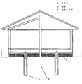
従来、地中熱を利用した空調システムとして、図8に示すような地中熱利用システムがあった。図において、床下に蓄熱用のくり石層1があり、地中2には地中パイプ3が埋設されている。くり石層1において蓄熱された地中熱を地中パイプ3により熱交換し、室内に送り込むというシステムであった(例えば、特許文献1参照)。
【0003】
【特許文献1】
特許第3030022号公報(第5頁、第1図)
【0004】
【発明が解決しようとする課題】
しかしながら、従来の地中熱利用システムは、地中パイプを用いて地中熱を室内に送り込み空調として利用するものであり、温度や空気の流れなどを制御することができないという課題を有していた。
【0005】
そこで本発明は、地中熱を用いるとともに地中熱から得られる温度や空気の流れなどを制御し、より効率のよい地中熱利用システムを提供することを目的とする。
【0006】
【課題を解決するための手段】
上記課題を解決するために本発明は、地中から熱交換器へ移送される気体の流れる第1のパイプと、熱交換器から地中へ移送される気体の流れる第2のパイプと、第1のパイプと第2のパイプ内の気体を地中と熱交換器の間で循環させる気体移送機と、前記熱交換器に風を送って熱交換後の風を室内に吹き出す送風機とを備えるとともに、前記第1のパイプに切り替え機を設け、地中から熱交換器へ移送される気体の流れを前記送風機へ流す場合と室内に直接流す場合とに切り替え制御するとともに、前記熱交換器には温度センサ及び補助ヒータを設け、前記熱交換器へ移送される気体の前記温度センサにより測定された温度が予め定められた温度より低い場合に補助ヒータを作動して前記気体を加熱するように構成した地中熱利用システムである。
【0007】
この構成により、夏季には地中熱により冷却された気体を用いて冷風を効率よく送ることができ、また冬季には地中熱により温められた気体を用いて温風を効率よく送ることができる。
【0008】
【発明の実施の形態】
本発明は、地中から熱交換器へ移送される気体の流れる第1のパイプと、熱交換器から地中へ移送される気体の流れる第2のパイプと、第1のパイプと第2のパイプ内の気体を地中と熱交換器の間で循環させる気体移送機と、前記熱交換器に風を送って熱交換後の風を室内に吹き出す送風機とを備えるとともに、前記第1のパイプに切り替え機を設け、地中から熱交換器へ移送される気体の流れを前記送風機へ流す場合と室内に直接流す場合とに切り替え制御するとともに、前記熱交換器には温度センサ及び補助ヒータを設け、前記熱交換器へ移送される気体の前記温度センサにより測定された温度が予め定められた温度より低い場合に補助ヒータを作動して前記気体を加熱する構成としてある。
【0009】
この構成により、特に冬季において、室内が地中の温度より非常に低い場合には切り替え機を作動して室内に地中熱を直接取りいれ、室内が地中の温度近傍に上昇した後は再度切り替え機を作動して熱交換器から室内に温風を送ることが可能となり、より効率のよい空調ができる。
【0010】
特に冬季において地中熱だけでは室内が充分に暖まらない場合に補助ヒータを用いて室内を暖めることができ好ましい。
【0011】
また、上記のように構成した熱交換器を給湯機や床暖房といった熱利用システムに接続したものであり、効率よく安定したエネルギシステムを実現することができる。
【0012】
【実施例】
(参考例1)
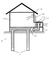
本発明の実施例を説明するに際し、まず本発明を理解するうえで参考となる参考例を図1を用いて説明する。図1において、4は家屋であり、地表面5から地中6にわたって地中パイプ7が設けられており地中パイプ7は外パイプ8と内パイプ9から構成されている。内パイプ9は下方が開放されており外パイプ8と繋がっており、気体移送機10により移送される気体を地中パイプ7内で外パイプ8と内パイプ9を通して循環させている。
【0013】
地中パイプ7の一端には熱交換器11が接続されており、その熱交換器11に風を送るように送風機12が配置されている。なお、13は家屋4の室内を示す。
【0014】
上記のように構成された地中熱利用システムについてその動作を説明する。気体移送機10により内パイプ9を通り地中6に送られた気体は外パイプ8を通り気体移送機10に再度送られる間に地中熱により温められる。温められた地中熱は熱交換器11に送られ送風機12から送られる風を受け、夏季であれば温風を、冬季であれば冷風を室内13に送り込む。
【0015】
このように熱交換器11と送風機12を用いることで、送風機12の風量や風速などを調整することで地中熱を利用した温風または冷風の温度や風量などを調整することができるため効率よく空調を行うことができる。
【0016】
なお、地中熱は一般に、地表面5から約1.5mまでは頻繁に温度が変化するが、約1.5mより深くなると摂氏15度付近で安定していることが知られている。従って、本発明においても、地中パイプ7は地中熱が安定している領域に届くように適宜構成することが好ましい。
【0017】
また、本参考例においては、気体移送機10により内パイプ9を通り地中6に送られた気体は外パイプ8を通り気体移送機10に再度送られる構成にしたが、気体移送機10により外パイプ8を通り地中6に送られた気体が内パイプ9を通り気体移送機10に再度送られるように構成してもよい。なお、外パイプ8と内パイプ9は一体に構成していても別体に構成していてもよく、何本設けるかは任意である。さらには、地中パイプ7内を循環する気体は、熱伝導性のあるものであればよい。
【0018】
また、上記のような地中熱利用システムの熱交換器11を床暖房や給湯機といった熱利用システムに接続することによって効率よく安定したエネルギシステムを実現することができる。
【0019】
(参考例2)
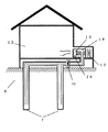
本発明の参考例2について図2及び図3を用いて説明する。図において参考例1と同一部材については同一符号を用いて説明を省略する。また、地中パイプ7内の気体が熱交換器11に移送される動作も参考例1と同様であるため説明を省略する。図2において14はヒートポンプの室外機であり、送風機12から熱交換器11へ送られた風を受ける位置に配置されており、冷媒移送管15を介して室内機16に接続されている。
【0020】
上記のように構成された地中熱利用システムにおいてその動作を説明する。地中熱で温められた気体は熱交換器11に移送され送風機12から風を受けてヒートポンプの室外機14に夏季であれば冷風を、冬季であれば温風を送る。その風を受けてヒートポンプの室外機14の冷媒は夏季であれば冷やされ、冬季であれば温められて冷媒移送管15を通って室内機16から室内13に夏季であれば冷風が、冬季であれば温風が送られる。
【0021】
この構成により、地中熱を利用してヒートポンプが室内を夏季であれば冷やし、冬季であれば暖める能力を補助することができ、ヒートポンプの冷却効率及び暖房効率といった成績係数を向上することができる。また、ヒートポンプは家屋に予め設置されたものを用いてもよく、その場合は工事が簡便になり好ましい。
【0022】
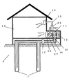
なお、本参考例においては熱交換器11、送風機12及びヒートポンプの室外機14を室内に設けたが、図3のように室外に設けても構わない。
【0023】
また、上記のような地中熱利用システムの熱交換器11を床暖房や給湯機といった熱利用システムに接続することによって効率よく安定したエネルギシステムを実現することができる。
【0024】
(参考例3)
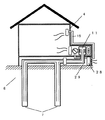
本発明の参考例3について図4を用いて説明する。図において前記参考例と同一部材については同一符号を用いて説明を省略する。また、地中パイプ7内の気体が熱交換器18に移送される動作も参考例1と同様であるため説明を省略する。図4において、熱交換器18は補助ヒータ19及び温度センサ20を備える。
【0025】
上記のように構成された地中熱利用システムについてその動作を説明する。地中熱で温められた気体は熱交換器11に移送され送風機12から風を受けて室内13に送られる。特に冬季において、温度センサ20が作動し熱交換器18に移送された気体の温度を測定する。測定された温度が予め定められた温度より低い場合には、室内13は肌寒いと考えられるため、補助ヒータ19を作動して熱交換器18内の気体の温度をより高め温風を室内に送る。
【0026】
この構成により、特に冬季において地中熱だけでは室内が充分に暖まらない場合に補助ヒータを用いて室内を暖めることができ、効率よく空調を行うことができる。
【0027】
また、上記のような地中熱利用システムの熱交換器18を床暖房や給湯機といった熱利用システムに接続することによって効率よく安定したエネルギシステムを実現することができる。
【0028】
(参考例4)
本発明の参考例4について図5を用いて説明する。図において前記参考例と同一部材については同一符号を用いて説明を省略する。また、地中パイプ7内の気体が熱交換器11に移送される動作も参考例1と同様であるため説明を省略する。
【0029】
熱交換器11は気体通路23に接続しており、気体通路切り替え機24により複数の室内吹き出し口16及び25に流れる気体の流れを制御している。室内吹き出し口16は冷媒移送管15を介してヒートポンプ室外機26及び気体通路切り替え機24に接続されている。また、室内吹き出し口25付近には温度センサ27が配置されている。
【0030】
上記のように構成された地中熱利用システムにおいて、その動作を説明する。熱交換器11に移送された地中パイプ7内に気体は、送風機12からの風により夏季であれば冷風を、冬季であれば温風を気体通路23に送る。
【0031】
その後、夏季であれば気体通路切り替え機24を用いて室内吹き出し口25に冷風を送り、室内13の温度を低くする。なお、その際に、冷風を循環させるため、適宜気体通路切り替え機24を設定してヒートポンプ室外機26側に風を流し冷媒移送路15内の冷媒を冷やして室内吹き出し口16から冷風を出し効率よく室内13を冷やすようにすることもできる。
【0032】
また、冬季であれば、温度センサ27により測定される室内13の温度に基づき、室温が地中熱の温度よりも低い場合には気体通路切り替え機24を用いて室内吹き出し口25から温風が室内13に送られる。
【0033】
室温が地中熱の温度付近に近づいた場合にも、地中熱の温度は摂氏15度前後のためより一層の暖房が必要となることもある。その際には、気体通路切り替え機24を用いてヒートポンプの室外機26側に温風を送り、冷媒移送管15内の冷媒を温めることにより地中熱より高い温度の温風を室内吹き出し口16から室内13に送る。
【0034】
この構成により、夏季においても冬季においても安定して室内13の温度を保つことができる。また、冬季においては予め設置されたヒートポンプを用いており、そのヒートポンプの冷房効率や暖房効率といった成績係数を向上することができる。
【0035】
なお、本参考例においては、ヒートポンプの室外機26を熱交換器11などを配置している上に置くようにしているが、図6のようにヒートポンプの室外機28を床下29に配置するようにしてもよい。なお、この場合、冷媒移送管15の長さが長くなるため、冷媒が温められる時間も長くなるため好ましい。
【0036】
また、上記のような地中熱利用システムの熱交換器11を床暖房や給湯機といった熱利用システムに接続することによって効率よく安定したエネルギシステムを実現することができる。
【0037】
(実施例1)
次に本発明の実施例1について図7を用いて説明する。図において前記参考例と同一部材については同一符号を用いて説明を省略する。図において、地中パイプ7は外パイプ30と内パイプ31とにより別体に構成され、外パイプ30の途中には切り替え機32を設け、外パイプ30を通る気体の流れを制御している。また、室内には温度センサ20とは別に第2の温度センサ33が設置されている。
【0038】
上記のように構成された地中熱利用システムにおいてその動作を説明する。気体移送機10により内パイプ31を通り地中6に送られた気体は外パイプ30を通り気体移送機10に再度送られる間に地中熱により夏季であれば冷やされ、冬季であれば温められる。
【0039】
夏季には、外パイプ30を通り熱交換器18に移送された気体は送風機12からの風を受け、室内13に冷風を送り室温を冷やす。
【0040】
冬季には、第2の温度センサ33が作動し、室内13の温度を測定しその温度が地中熱の温度より低い場合には切り替え機32が温められた気体を直接室内13に入れるように設定される。
【0041】
また、第2の温度センサ33が測定した室温が地中熱の温度付近になると切り替え機32は外パイプ30内の気体を気体移送機10側に送り、熱交換器18へ移送される。温度センサ20により外パイプ30及び内パイプ31内の気体の温度が測定され、その温度が予め定められた温度より低い場合には、室内13は肌寒いと考えられるため、補助ヒータ19を作動して熱交換器18内の気体の温度をより高め温風を室内に送る。
【0042】
この構成により、特に冬季において、直接室内を暖めることができるとともに温度センサ20及び第2の温度センサ33を用いることで室内13の温度を安定した温度に保つことができる。
【0043】
なお、本実施例においては、温度センサ20及び第2の温度センサ33というように2つのセンサを設けたが、どちらか一方にしてもよく、1つのセンサで室内13及び熱交換器18の両方を測定できるようにしてもよい。
【0044】
また、上記のような地中熱利用システムの熱交換器18を床暖房や給湯機といった熱利用システムに接続することによって効率よく安定したエネルギシステムを実現することができる。
【0045】
【発明の効果】
上記のように本発明は、夏季には地中熱により冷却された気体を用いて冷風を効率よく送ることができ、また冬季には地中熱により温められた気体を用いて温風を効率よく送ることができる。特に冬季において、室内が地中の温度より非常に低い場合には切り替え機を作動して室内に地中熱を直接取りいれ、室内が地中の温度近傍に上昇した後は再度切り替え機を作動して熱交換器から室内に温風を送ることが可能となり、より効率のよい空調ができる。
【図面の簡単な説明】
【図1】 本発明の参考例1を示す地中熱利用システムの概略図
【図2】 本発明の参考例2の地中熱利用システムの概略図
【図3】 本発明の参考例2の地中熱利用システムの概略図
【図4】 本発明の参考例3の地中熱利用システムの概略図
【図5】 本発明の参考例4の地中熱利用システムの概略図
【図6】 本発明の参考例4の地中熱利用システムの概略図
【図7】 本発明の実施例1の地中熱利用システムの概略図
【図8】 従来の地中熱利用システムの概略図
【符号の説明】
7 地中パイプ
8 外パイプ
9 内パイプ
10 気体移送機
11 熱交換器
12 送風機[0001]
BACKGROUND OF THE INVENTION
The present invention relates to a system for air-conditioning a building such as a house or an office using stable heat in the ground.
[0002]
[Prior art]
Conventionally, as an air conditioning system using geothermal heat, there has been a geothermal heat utilization system as shown in FIG. In the figure, a
[0003]
[Patent Document 1]
Japanese Patent No. 3030022 (5th page, Fig. 1)
[0004]
[Problems to be solved by the invention]
However, the conventional geothermal heat utilization system uses underground pipes to send ground heat into the room and uses it as air conditioning, and has a problem that it cannot control temperature, air flow, etc. It was.
[0005]
Accordingly, an object of the present invention is to provide a more efficient geothermal heat utilization system by using geothermal heat and controlling the temperature and air flow obtained from the geothermal heat.
[0006]
[Means for Solving the Problems]
In order to solve the above-mentioned problems, the present invention provides a first pipe through which a gas transferred from the ground to the heat exchanger flows, a second pipe through which a gas transferred from the heat exchanger to the ground, A gas transfer device that circulates the gas in the first pipe and the second pipe between the ground and the heat exchanger; and a blower that sends air to the heat exchanger and blows the air after heat exchange into the room. In addition, a switching device is provided in the first pipe, and the flow of the gas transferred from the ground to the heat exchanger is controlled to be switched between flowing to the blower and flowing directly into the room, and the heat exchanger Is provided with a temperature sensor and an auxiliary heater, and when the temperature measured by the temperature sensor of the gas transferred to the heat exchanger is lower than a predetermined temperature, the auxiliary heater is operated to heat the gas. Constructed geothermal heat utilization system A.
[0007]
With this configuration, cool air can be sent efficiently using gas cooled by underground heat in summer, and hot air can be sent efficiently using gas heated by underground heat in winter. it can.
[0008]
DETAILED DESCRIPTION OF THE INVENTION
The present invention includes a first pipe through which a gas transferred from the ground to a heat exchanger flows, a second pipe through which a gas transferred from the heat exchanger into the ground, a first pipe, and a second pipe The first pipe includes a gas transfer device that circulates the gas in the pipe between the ground and the heat exchanger, and a blower that sends air to the heat exchanger and blows out the air after heat exchange into the room. And switching control between the case where the flow of gas transferred from the ground to the heat exchanger flows to the blower and the case where it directly flows into the room, and the heat exchanger is provided with a temperature sensor and an auxiliary heater. The auxiliary heater is operated to heat the gas when the temperature measured by the temperature sensor of the gas transferred to the heat exchanger is lower than a predetermined temperature.
[0009]
With this configuration, especially in the winter, when the room is very cooler than the underground temperature, the switcher is operated to directly take in the underground heat and switch again after the room rises near the underground temperature. By operating the machine, it becomes possible to send warm air from the heat exchanger to the room, and more efficient air conditioning can be achieved.
[0010]
Particularly in the winter season, it is preferable that the room can be warmed by using an auxiliary heater when the room is not sufficiently warmed only by underground heat.
[0011]
Further, the heat exchanger configured as described above is connected to a heat utilization system such as a water heater or floor heating, and an efficient and stable energy system can be realized.
[0012]
【Example】
(Reference Example 1)
In describing an embodiment of the present invention, first, a reference example to be referred to in understanding the present invention will be described with reference to FIG. In FIG. 1,
[0013]
A heat exchanger 11 is connected to one end of the
[0014]
The operation of the underground heat utilization system configured as described above will be described. The gas sent to the
[0015]
Since the heat exchanger 11 and the air blower 12 are used in this way, the temperature and air flow of the hot air or the cold air using the geothermal heat can be adjusted by adjusting the air volume and the air speed of the air blower 12 and the efficiency. Air conditioning can be performed well.
[0016]
It is known that the underground heat generally changes frequently from the
[0017]
Moreover, in this reference example, the gas sent to the
[0018]
Further, an efficient and stable energy system can be realized by connecting the heat exchanger 11 of the above-described underground heat utilization system to a heat utilization system such as floor heating or a hot water heater.
[0019]
(Reference Example 2)
Reference Example 2 of the present invention will be described with reference to FIGS. In the figure, the same members as those in Reference Example 1 are denoted by the same reference numerals, and description thereof is omitted. The operation of transferring the gas in the
[0020]
The operation of the geothermal heat utilization system configured as described above will be described. The gas heated by the underground heat is transferred to the heat exchanger 11, receives wind from the blower 12, and sends cool air to the
[0021]
With this configuration, it is possible to assist the ability of the heat pump to cool the room in the summer using the geothermal heat and warm it in the winter, and improve the coefficient of performance such as the cooling efficiency and the heating efficiency of the heat pump. . In addition, a heat pump that is preliminarily installed in the house may be used, and in that case, the construction is simple and preferable.
[0022]
In addition, in this reference example, although the heat exchanger 11, the air blower 12, and the
[0023]
Further, an efficient and stable energy system can be realized by connecting the heat exchanger 11 of the above-described underground heat utilization system to a heat utilization system such as floor heating or a hot water heater.
[0024]
(Reference Example 3)
Reference Example 3 of the present invention will be described with reference to FIG. In the figure, the same members as those in the reference example are denoted by the same reference numerals and the description thereof is omitted. Further, the operation of transferring the gas in the
[0025]
The operation of the underground heat utilization system configured as described above will be described. The gas heated by the underground heat is transferred to the heat exchanger 11, receives the wind from the blower 12, and is sent to the
[0026]
With this configuration, particularly in winter, when the room is not sufficiently warmed only by underground heat, the room can be warmed using the auxiliary heater, and air conditioning can be performed efficiently.
[0027]
Further, an efficient and stable energy system can be realized by connecting the heat exchanger 18 of the above-described underground heat utilization system to a heat utilization system such as floor heating or a hot water heater.
[0028]
(Reference Example 4)
Reference Example 4 of the present invention will be described with reference to FIG. In the figure, the same members as those in the reference example are denoted by the same reference numerals and the description thereof is omitted. The operation of transferring the gas in the
[0029]
The heat exchanger 11 is connected to the
[0030]
The operation of the geothermal heat utilization system configured as described above will be described. In the
[0031]
Thereafter, in the summer, the cool air is sent to the indoor outlet 25 using the
[0032]
In the winter season, based on the temperature of the
[0033]
Even when the room temperature approaches the temperature of the underground heat, the temperature of the underground heat is around 15 degrees Celsius, so that further heating may be required. At that time, warm air having a temperature higher than the underground heat is sent to the
[0034]
With this configuration, the temperature of the
[0035]
In this reference example, the
[0036]
Further, an efficient and stable energy system can be realized by connecting the heat exchanger 11 of the above-described underground heat utilization system to a heat utilization system such as floor heating or a hot water heater.
[0037]
Example 1
Next,
[0038]
The operation of the geothermal heat utilization system configured as described above will be described. The gas sent to the underground 6 through the
[0039]
In summer, the gas transferred to the heat exchanger 18 through the
[0040]
In winter, the
[0041]
Further, when the room temperature measured by the
[0042]
With this configuration, the interior of the
[0043]
In the present embodiment, two sensors such as the
[0044]
Further, an efficient and stable energy system can be realized by connecting the heat exchanger 18 of the above-described underground heat utilization system to a heat utilization system such as floor heating or a hot water heater.
[0045]
【The invention's effect】
As described above, the present invention can efficiently send cold air using a gas cooled by geothermal heat in summer, and can efficiently use hot air using a gas heated by underground heat in winter. Can send well. Especially in the winter, when the room is very cooler than the underground temperature, the switcher is operated to directly take the underground heat into the room, and after the room rises near the underground temperature, the switcher is operated again. Therefore, it becomes possible to send warm air from the heat exchanger into the room, and air conditioning can be performed more efficiently.
[Brief description of the drawings]
FIG. 1 is a schematic diagram of a geothermal heat utilization system showing a reference example 1 of the present invention. FIG. 2 is a schematic diagram of a geothermal heat utilization system of a reference example 2 of the present invention. Schematic diagram of geothermal heat utilization system [Fig. 4] Schematic diagram of geothermal heat utilization system of Reference Example 3 of the present invention [Fig. 5] Schematic diagram of geothermal heat utilization system of Reference Example 4 of the present invention [Fig. 6] Schematic diagram of the geothermal heat utilization system of Reference Example 4 of the present invention. [Fig. 7] Schematic diagram of the geothermal heat utilization system of Example 1 of the present invention. [Fig. Explanation of]
7
Claims (2)
Priority Applications (1)
| Application Number | Priority Date | Filing Date | Title |
|---|---|---|---|
| JP2003097876A JP4457571B2 (en) | 2003-04-01 | 2003-04-01 | Geothermal utilization system |
Applications Claiming Priority (1)
| Application Number | Priority Date | Filing Date | Title |
|---|---|---|---|
| JP2003097876A JP4457571B2 (en) | 2003-04-01 | 2003-04-01 | Geothermal utilization system |
Publications (2)
| Publication Number | Publication Date |
|---|---|
| JP2004301470A JP2004301470A (en) | 2004-10-28 |
| JP4457571B2 true JP4457571B2 (en) | 2010-04-28 |
Family
ID=33409552
Family Applications (1)
| Application Number | Title | Priority Date | Filing Date |
|---|---|---|---|
| JP2003097876A Expired - Fee Related JP4457571B2 (en) | 2003-04-01 | 2003-04-01 | Geothermal utilization system |
Country Status (1)
| Country | Link |
|---|---|
| JP (1) | JP4457571B2 (en) |
Families Citing this family (13)
| Publication number | Priority date | Publication date | Assignee | Title |
|---|---|---|---|---|
| JP4632760B2 (en) * | 2004-11-25 | 2011-02-16 | 旭化成ホームズ株式会社 | Geothermal equipment |
| DE102005038512A1 (en) * | 2005-07-29 | 2007-02-01 | Maico Elektroapparate-Fabrik Gmbh | Method and device for operating a tempered room ventilation |
| KR100800328B1 (en) | 2006-11-27 | 2008-02-01 | 김재휘 | Heat pump using underground air as heat source |
| JP2011153764A (en) * | 2010-01-27 | 2011-08-11 | Fujitsu Ltd | Air conditioning control system, air conditioning control method and air conditioning control program |
| JP2012163239A (en) * | 2011-02-04 | 2012-08-30 | Sekisui Chem Co Ltd | Geothermal heat utilization apparatus |
| KR101261057B1 (en) | 2011-11-30 | 2013-05-06 | 코오롱글로벌 주식회사 | Heat pump apparatus using cool tube and heating and cooling method using thereof |
| CN102840725B (en) * | 2012-09-27 | 2014-07-16 | 山东中瑞新能源科技有限公司 | Control system and method of buried pipe and cooling tower ground source heat pump compound system |
| JP5932692B2 (en) * | 2013-03-19 | 2016-06-08 | 岡谷鋼機株式会社 | Heat storage device |
| CN103363700B (en) * | 2013-07-04 | 2016-02-03 | 吉林大学 | Underground heat exchange pipe frost-heaving deformation Active Control Method |
| JP7320308B2 (en) * | 2018-09-19 | 2023-08-03 | 株式会社リビエラ | Auxiliary heat exchange device |
| JP7109781B2 (en) * | 2018-09-19 | 2022-08-01 | 株式会社リビエラ | Auxiliary heat exchange device |
| JP7045744B1 (en) | 2021-11-01 | 2022-04-01 | 俊明 前田 | Air heat collection system |
| CN115076814A (en) * | 2022-06-25 | 2022-09-20 | 中建七局第四建筑有限公司 | Indoor temperature control system for geothermal energy |
Family Cites Families (5)
| Publication number | Priority date | Publication date | Assignee | Title |
|---|---|---|---|---|
| JPS57195030U (en) * | 1980-12-15 | 1982-12-10 | ||
| JPH11182942A (en) * | 1997-12-25 | 1999-07-06 | Kubota Corp | Underground heat exchanger |
| JP3030022B2 (en) * | 1998-04-10 | 2000-04-10 | 株式会社東光工業 | Air conditioning system using natural power of building |
| JP3727229B2 (en) * | 2000-09-08 | 2005-12-14 | 独立行政法人科学技術振興機構 | Air circulation type air conditioning system |
| JP2003021360A (en) * | 2001-07-05 | 2003-01-24 | Ground System Corp | Air conditioning system using soil heat and heat exchange device in soil |
-
2003
- 2003-04-01 JP JP2003097876A patent/JP4457571B2/en not_active Expired - Fee Related
Also Published As
| Publication number | Publication date |
|---|---|
| JP2004301470A (en) | 2004-10-28 |
Similar Documents
| Publication | Publication Date | Title |
|---|---|---|
| JP4457571B2 (en) | Geothermal utilization system | |
| CN101821562B (en) | Heat pump device | |
| JP6548088B2 (en) | Air conditioning system | |
| CN102667348A (en) | Arrangement for air conditioning rooms and heat pump unit for use in the arrangement | |
| JP2011141073A (en) | Device and method of improving efficiency of air conditioning device | |
| JP2005009737A (en) | Geothermal air conditioning system | |
| JP2003021360A (en) | Air conditioning system using soil heat and heat exchange device in soil | |
| JP2005024140A (en) | Air conditioning system of building, and air conditioning/hot-water supply system of building | |
| JP7008347B2 (en) | Hot water and energy storage | |
| JP4376023B2 (en) | Heat utilization equipment for air conditioning | |
| JP2010014296A (en) | Air conditioning system and unit building | |
| JP3441406B2 (en) | Area cooling and heating system thermal storage system | |
| CN101182950A (en) | A building system | |
| JP2001194012A (en) | Solar hot water supply and heating system | |
| JP4404731B2 (en) | Air-conditioning system using geothermal heat | |
| JP3873259B1 (en) | Heat storage device and air conditioner | |
| WO2008096157A1 (en) | A method of changing the temperature of a thermal load | |
| JP2005098594A (en) | Geothermal exchange system | |
| CN214536618U (en) | Air conditioner | |
| JP4471164B2 (en) | Heat exchange system | |
| JP2012159220A (en) | Heat storage type heat exchanger and air conditioning system using the same | |
| JP2009264702A (en) | Air conditioning system, unitized building and air conditioning method | |
| JP2005155937A (en) | Air conditioner, and heating apparatus | |
| JP2001311556A (en) | Solar thermal system | |
| JP4462462B2 (en) | Air conditioning and heat storage system using body heat storage |
Legal Events
| Date | Code | Title | Description |
|---|---|---|---|
| A621 | Written request for application examination |
Free format text: JAPANESE INTERMEDIATE CODE: A621 Effective date: 20060324 |
|
| RD01 | Notification of change of attorney |
Free format text: JAPANESE INTERMEDIATE CODE: A7421 Effective date: 20060412 |
|
| A131 | Notification of reasons for refusal |
Free format text: JAPANESE INTERMEDIATE CODE: A131 Effective date: 20080708 |
|
| A521 | Written amendment |
Free format text: JAPANESE INTERMEDIATE CODE: A523 Effective date: 20080905 |
|
| A131 | Notification of reasons for refusal |
Free format text: JAPANESE INTERMEDIATE CODE: A131 Effective date: 20081007 |
|
| A521 | Written amendment |
Free format text: JAPANESE INTERMEDIATE CODE: A523 Effective date: 20081201 |
|
| A131 | Notification of reasons for refusal |
Free format text: JAPANESE INTERMEDIATE CODE: A131 Effective date: 20090602 |
|
| A521 | Written amendment |
Free format text: JAPANESE INTERMEDIATE CODE: A523 Effective date: 20090717 |
|
| RD01 | Notification of change of attorney |
Free format text: JAPANESE INTERMEDIATE CODE: A7421 Effective date: 20091119 |
|
| TRDD | Decision of grant or rejection written | ||
| A01 | Written decision to grant a patent or to grant a registration (utility model) |
Free format text: JAPANESE INTERMEDIATE CODE: A01 Effective date: 20100119 |
|
| A01 | Written decision to grant a patent or to grant a registration (utility model) |
Free format text: JAPANESE INTERMEDIATE CODE: A01 |
|
| A61 | First payment of annual fees (during grant procedure) |
Free format text: JAPANESE INTERMEDIATE CODE: A61 Effective date: 20100201 |
|
| FPAY | Renewal fee payment (event date is renewal date of database) |
Free format text: PAYMENT UNTIL: 20130219 Year of fee payment: 3 |
|
| LAPS | Cancellation because of no payment of annual fees |