EP0909933A1 - Cross-flow heat exchanger with bypass-valve - Google Patents
Cross-flow heat exchanger with bypass-valve Download PDFInfo
- Publication number
- EP0909933A1 EP0909933A1 EP98203429A EP98203429A EP0909933A1 EP 0909933 A1 EP0909933 A1 EP 0909933A1 EP 98203429 A EP98203429 A EP 98203429A EP 98203429 A EP98203429 A EP 98203429A EP 0909933 A1 EP0909933 A1 EP 0909933A1
- Authority
- EP
- European Patent Office
- Prior art keywords
- heat exchanger
- flow
- walls
- valve
- cavity
- Prior art date
- Legal status (The legal status is an assumption and is not a legal conclusion. Google has not performed a legal analysis and makes no representation as to the accuracy of the status listed.)
- Granted
Links
Images

Classifications
-
- F—MECHANICAL ENGINEERING; LIGHTING; HEATING; WEAPONS; BLASTING
- F28—HEAT EXCHANGE IN GENERAL
- F28F—DETAILS OF HEAT-EXCHANGE AND HEAT-TRANSFER APPARATUS, OF GENERAL APPLICATION
- F28F27/00—Control arrangements or safety devices specially adapted for heat-exchange or heat-transfer apparatus
- F28F27/02—Control arrangements or safety devices specially adapted for heat-exchange or heat-transfer apparatus for controlling the distribution of heat-exchange media between different channels
-
- F—MECHANICAL ENGINEERING; LIGHTING; HEATING; WEAPONS; BLASTING
- F24—HEATING; RANGES; VENTILATING
- F24F—AIR-CONDITIONING; AIR-HUMIDIFICATION; VENTILATION; USE OF AIR CURRENTS FOR SCREENING
- F24F12/00—Use of energy recovery systems in air conditioning, ventilation or screening
- F24F12/001—Use of energy recovery systems in air conditioning, ventilation or screening with heat-exchange between supplied and exhausted air
- F24F12/006—Use of energy recovery systems in air conditioning, ventilation or screening with heat-exchange between supplied and exhausted air using an air-to-air heat exchanger
-
- F—MECHANICAL ENGINEERING; LIGHTING; HEATING; WEAPONS; BLASTING
- F28—HEAT EXCHANGE IN GENERAL
- F28D—HEAT-EXCHANGE APPARATUS, NOT PROVIDED FOR IN ANOTHER SUBCLASS, IN WHICH THE HEAT-EXCHANGE MEDIA DO NOT COME INTO DIRECT CONTACT
- F28D9/00—Heat-exchange apparatus having stationary plate-like or laminated conduit assemblies for both heat-exchange media, the media being in contact with different sides of a conduit wall
-
- F—MECHANICAL ENGINEERING; LIGHTING; HEATING; WEAPONS; BLASTING
- F24—HEATING; RANGES; VENTILATING
- F24F—AIR-CONDITIONING; AIR-HUMIDIFICATION; VENTILATION; USE OF AIR CURRENTS FOR SCREENING
- F24F12/00—Use of energy recovery systems in air conditioning, ventilation or screening
- F24F12/001—Use of energy recovery systems in air conditioning, ventilation or screening with heat-exchange between supplied and exhausted air
- F24F2012/007—Use of energy recovery systems in air conditioning, ventilation or screening with heat-exchange between supplied and exhausted air using a by-pass for bypassing the heat-exchanger
-
- F—MECHANICAL ENGINEERING; LIGHTING; HEATING; WEAPONS; BLASTING
- F28—HEAT EXCHANGE IN GENERAL
- F28F—DETAILS OF HEAT-EXCHANGE AND HEAT-TRANSFER APPARATUS, OF GENERAL APPLICATION
- F28F2250/00—Arrangements for modifying the flow of the heat exchange media, e.g. flow guiding means; Particular flow patterns
- F28F2250/06—Derivation channels, e.g. bypass
-
- Y—GENERAL TAGGING OF NEW TECHNOLOGICAL DEVELOPMENTS; GENERAL TAGGING OF CROSS-SECTIONAL TECHNOLOGIES SPANNING OVER SEVERAL SECTIONS OF THE IPC; TECHNICAL SUBJECTS COVERED BY FORMER USPC CROSS-REFERENCE ART COLLECTIONS [XRACs] AND DIGESTS
- Y02—TECHNOLOGIES OR APPLICATIONS FOR MITIGATION OR ADAPTATION AGAINST CLIMATE CHANGE
- Y02B—CLIMATE CHANGE MITIGATION TECHNOLOGIES RELATED TO BUILDINGS, e.g. HOUSING, HOUSE APPLIANCES OR RELATED END-USER APPLICATIONS
- Y02B30/00—Energy efficient heating, ventilation or air conditioning [HVAC]
- Y02B30/56—Heat recovery units
Definitions
- the invention relates to a cross-flow heat exchanger for use in a space heating system which is adapted for heating air by means of a burner;
- the first through-flow circuit it is often found to be desirable for the first through-flow circuit to comprise a part through which not all cold outside air reaches the space for heating in preheated state. In certain conditions it may be desired to feed a fraction of the admitted outside air unheated to the space for heating. It is per se known for this purpose to incorporate a bypass through-flow circuit parallel to the first through-flow circuit of the heat exchanger.
- the object of the invention is to embody a cross-flow heat exchanger such that it combines the two said functions, i.e. the first through-flow circuit for heating outside air and the bypass through-flow circuit.
- the heat exchanger according to the invention has the feature that in the prismatic form a smaller prismatic part serving as bypass circuit with the same section transversely of the main direction is free of walls and comprises a cavity bounded by two walls, which cavity forms part of the first through-flow circuit, in which cavity is arranged a valve which is displaceable between a closed position and an open position by means of control means coupled to the valve, which valve comprises a shaft rotatable by a drive, which shaft has an axis of rotation extending substantially in transverse direction relative to the flow direction of the first through-flow circuit and bears a substantially plate-like element which extends substantially over the whole transverse dimension of said smaller prismatic part, extends between the side walls of the smaller prismatic part in the closed position of the valve, and is at a distance from at least one of these side walls in the open position of the valve.
- a preferred embodiment has the special feature that the axis is placed symmetrically in relation to said side walls.
- This embodiment has the advantage that the air flowing along loads the plate-like element symmetrically, which element must of course be embodied symmetrically relative to the axis.
- the valve can hereby also be rotated with very little effort when air is flowing by, since no resistance is encountered by the air flowing by. In the stationary situation the drive with this structure is not under strain of rotation either.
- cross-flow heat exchanger further has the special feature that the plate-like element is mounted rotatably at both its ends.
- the plate-like element is mounted rotatably at both its ends.
- a specific embodiment has the special feature that the drive comprises a motor with a reduction gearing.
- the drive comprises a motor with a reduction gearing.
- a smooth displacement of the plate-like element can hereby be realized, wherein the force can be sufficiently large under all conditions owing to the slow movement.
- a simple embodiment has the special feature that the drive comprises two limit switches which respectively determine the open and the closed position of the valve.
- This structure has the advantage that both end positions can be determined with very simple, reliable and inexpensive means.
- the drive comprises a stepping motor.
- a stepping motor enables in simple manner a possibly desired intermediate position. Such an intermediate position could in principle also be achieved with an ordinary motor.
- position pick-up means must be used to signal the momentary position of the plate-like valve element to the control means, which respond thereto by comparing the momentary position with a nominal position set by a user or determined on the basis of program control and external signals.
- control means are connectable for control purposes to an outdoor temperature sensor.
- the system according to the invention is a system which is used in a space heating system with heat recovery. Contaminated inside air is replaced by fresh outside air, wherein exchange of thermal energy takes place between the heated inside air to be discharged and the still unheated, incoming outside air.
- the present invention start from the principle that in the space heating system a cross-flow heat exchanger must be present which must itself be provided with the bypass system. This provides the possibility of a very simple structure.
- the heat exchanger according to the invention has the particular feature that the heat exchanger has the same general form as a known heat exchanger and is therefore interchangeable therewith.
- the heat exchanger can also have the special feature that the prismatic part serving as bypass circuit is a separate unit.
- Such a relatively small prismatic part serving as bypass circuit forms a plug-in module and can be placed in a heat exchanger which is provided with an empty space adapted for this purpose in which said relatively small prismatic part fits.
- control means which can comprise for instance a microprocessor or the like, are connectable for control to an outdoor temperature sensor.
- the system can for instance have the following functional situations:
- Said levels of 15°C and 20°C are stated by way of example.
- the system can be designed for instance such that the user of the space heating system can adjust these temperatures.
- the described adjustment can result in a lesser heating of the dwelling in the summer during the day (when it is warm outside) and a more rapid cooling of the dwelling during the night (when it is relatively cool outside).
- Figure 1 shows a part of a space heating device 1.
- a cross-flow heat exchanger 2 is incorporated therein.
- an inlet 2 cold outside air is fed to heat exchanger 2 via a first intake cavity 4.
- a first discharge cavity 5 the heated outside air, which has passed through heat exchanger 2 via a first through-flow circuit, is discharged by a fan 6 to an outlet 7 through which heated air is guided to the space for heating.
- the air extracted from the space is fed via a second intake cavity 8 to a second through-flow circuit of heat exchanger 2 and discharged therefrom via a second discharge cavity 10 to an outlet 11 for discharge to the outside.
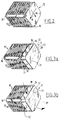
- FIG. 2 shows a known heat exchanger 12.
- This is of the cross-flow type with two through-flow circuits which are physically separated from each other and thermally coupled to each other by means of a number of parallel walls 13, for instance of aluminium. These circuits are mutually interwoven and flow therethrough can take place in mutually transverse direction.
- the general direction of said two through-flow circuits is indicated on the right-hand end wall by means of two arrows 14, 15.
- the embodiment of this heat exchanger 12 is generally known.
- the walls 13 are held in mutual connection by means of construction means 16.
- heat exchanger 2 has a substantially prismatic form, the main direction of which parallel to the generating lines extends transversely of the main planes of the walls.
- Heat exchanger 17 as according to figures 3a and 3b has the same generally prismatic form as heat exchanger 12 of figure 2. It is hereby fully interchangeable with this heat exchanger 12.
- Heat exchanger 17 has the special feature relative to heat exchanger 12 that in the prismatic form a smaller prismatic form 18 with the same section transversely of the main direction is free of walls and thus comprises a cavity 18 bounded by two walls.
- This cavity 18 forms part of the first through-flow circuit which for heat exchanger 12 is designated with 14 in figure 2.
- the cavity is therefore bounded at the sides by two walls 19, 20.
- a plate 21 serving as valve body which is displaceable between a closed position as according to figure 3a and an open position as according to figure 3b. In the open position shown in figure 3b the valve is designated with 21'.
- Plate 21 is centrally mounted on its longitudinal ends in rotation bearings 31, 32 which together define a rotation axis which extends symmetrically relative to the prismatic part 18. Plate 21 is likewise placed symmetrically relative to the said axis. Plate 21 can thus be displaced between the closed position of figure 3a, in which the long side edges of plate 21 substantially connect onto walls 19, 20, and the open position, in which plate 21 extends in a plane extending more or less parallel to walls 19, 20.
- Rotation of plate 21 takes place with a drive 33 embodied in this case as stepping motor.
- Control thereof takes place by central control means, for instance comprising a microprocessor which is connected for instance to a space thermostat, an outdoor temperature sensor and control means which may comprise for instance a keyboard for operation by a user.
- the air flow through cavity 18 is not carried along the surfaces of heat exchanger 17. As a result of this bypass cavity 18 a direct through-flow of outside air therefore takes place outside the heat exchanger.
- a space heating system is generally known and applied on a large scale. Dwellings equipped with such a system must also remain ventilated by the intake fan during the summer. It is noted in this respect that it is not always desirable or even possible to open windows, for instance due to street noise. Adequate ventilation of the spaces in these dwellings is nevertheless necessary.
- the valve 21 is placed in its position 21'. Supply of air with a considerably reduced flow resistance by means of fan 6 is thus also ensured in the summer. This also results in a considerable reduction in the required capacity of fan 6.
- heat exchanger 17 according to figures 1 and 3 preferably has the same external form as the known heat exchanger of figure 2. Heat exchanger 17 can thus be used to replace the known heat exchanger 12.
- the invention also relates to a bypass unit which is adapted and intended for addition to a heat exchanger which is provided with a space for accommodating such a unit.
- This bypass unit according to the invention is specified in claim 10.
Abstract
Description
- The invention relates to a cross-flow heat exchanger for use in a space heating system which is adapted for heating air by means of a burner;
- which heat exchanger comprises two through-flow
circuits physically separated from each other and thermally
coupled to each other by means of a number of
parallel walls, which circuits are arranged in interwoven
relation and through which flow, in mutual transverse
direction, respectively
- (1) an air flow from an outside air inlet to a discharge to the space for heating
- (2) a gas flow from an inlet, for instance for hot flue gases coming from the burner, to a discharge for flue gases to the outside, or air coming from the space to a discharge therefor to the outside,
- which walls are all substantially congruent and are held in mutual connection by construction means, which heat exchanger generally has a substantially prismatic form, the main direction of which parallel to the generating lines extends transversely of the main planes of the walls.
-
- It is often found to be desirable for the first through-flow circuit to comprise a part through which not all cold outside air reaches the space for heating in preheated state. In certain conditions it may be desired to feed a fraction of the admitted outside air unheated to the space for heating. It is per se known for this purpose to incorporate a bypass through-flow circuit parallel to the first through-flow circuit of the heat exchanger.
- The object of the invention is to embody a cross-flow heat exchanger such that it combines the two said functions, i.e. the first through-flow circuit for heating outside air and the bypass through-flow circuit.
- To this end the heat exchanger according to the invention has the feature that in the prismatic form a smaller prismatic part serving as bypass circuit with the same section transversely of the main direction is free of walls and comprises a cavity bounded by two walls, which cavity forms part of the first through-flow circuit, in which cavity is arranged a valve which is displaceable between a closed position and an open position by means of control means coupled to the valve, which valve comprises a shaft rotatable by a drive, which shaft has an axis of rotation extending substantially in transverse direction relative to the flow direction of the first through-flow circuit and bears a substantially plate-like element which extends substantially over the whole transverse dimension of said smaller prismatic part, extends between the side walls of the smaller prismatic part in the closed position of the valve, and is at a distance from at least one of these side walls in the open position of the valve.
- A preferred embodiment has the special feature that the axis is placed symmetrically in relation to said side walls. This embodiment has the advantage that the air flowing along loads the plate-like element symmetrically, which element must of course be embodied symmetrically relative to the axis. The valve can hereby also be rotated with very little effort when air is flowing by, since no resistance is encountered by the air flowing by. In the stationary situation the drive with this structure is not under strain of rotation either.
- In preference the cross-flow heat exchanger further has the special feature that the plate-like element is mounted rotatably at both its ends. Thus is avoided, particularly in the closed situation, that the plate-like element is placed under strain of bending by air flowing by.
- A specific embodiment has the special feature that the drive comprises a motor with a reduction gearing. A smooth displacement of the plate-like element can hereby be realized, wherein the force can be sufficiently large under all conditions owing to the slow movement.
- A simple embodiment has the special feature that the drive comprises two limit switches which respectively determine the open and the closed position of the valve. This structure has the advantage that both end positions can be determined with very simple, reliable and inexpensive means.
- An alternative has the special feature that the drive comprises a stepping motor. A stepping motor enables in simple manner a possibly desired intermediate position. Such an intermediate position could in principle also be achieved with an ordinary motor. In that case however, position pick-up means must be used to signal the momentary position of the plate-like valve element to the control means, which respond thereto by comparing the momentary position with a nominal position set by a user or determined on the basis of program control and external signals.
- A specific embodiment has the special feature that the control means are connectable for control purposes to an outdoor temperature sensor.
- The system according to the invention is a system which is used in a space heating system with heat recovery. Contaminated inside air is replaced by fresh outside air, wherein exchange of thermal energy takes place between the heated inside air to be discharged and the still unheated, incoming outside air.
- In known systems there occurs a problem in a period, for instance a summer period, when the outdoor temperature is higher than the indoor temperature. In this case the system with heat recovery will begin to operate in reverse, and the space in question is heated in relation to the outdoor temperature. In certain conditions this may be undesirable. In most comparable devices with heat recovery, the supply ventilation is simply switched off in these conditions. If for some reason this is not possible, such as in the case of strongly noise-charged outside walls which make it impossible for instance to open windows for natural ventilation, or because of personal circumstances such as allergies, a bypass circuit must be applied. This bypass could optionally be arranged outside the space heating system. When the bypass is switched on, the outside air will be re-routed round the space heating system with heat recovery in the active state of the bypass.
- The present invention start from the principle that in the space heating system a cross-flow heat exchanger must be present which must itself be provided with the bypass system. This provides the possibility of a very simple structure.
- In a preferred embodiment the heat exchanger according to the invention has the particular feature that the heat exchanger has the same general form as a known heat exchanger and is therefore interchangeable therewith.
- The heat exchanger can also have the special feature that the prismatic part serving as bypass circuit is a separate unit. Such a relatively small prismatic part serving as bypass circuit forms a plug-in module and can be placed in a heat exchanger which is provided with an empty space adapted for this purpose in which said relatively small prismatic part fits.
- In respect of both this embodiment and the embodiment described in the foregoing paragraph, attention must be drawn in this case to the fact that the bypass space causes a certain decrease in the effective dimensions of the heat exchanger. In practice however, it is found that heat exchangers in space heating systems are amply dimensioned such that this does not pose a problem.
- One of the described embodiments is embodied such that the control means, which can comprise for instance a microprocessor or the like, are connectable for control to an outdoor temperature sensor.
- The system can for instance have the following functional situations:
- (1) Outside air temperature lower than 15°C; bypass closed; space heating system active. The supplied outside air is heated by the discharged inside air.
- (2) Outside air temperature lower than 15°C or higher than 20°C; bypass open; space heating system not active. The supplied outside air is carried directly to the space without being heated.
- (3) Outside air temperature lower than 20°C; bypass closed; space heating system active. The supplied outside air is heated by the discharged inside air.
-
- Said levels of 15°C and 20°C are stated by way of example. The system can be designed for instance such that the user of the space heating system can adjust these temperatures.
- The described adjustment can result in a lesser heating of the dwelling in the summer during the day (when it is warm outside) and a more rapid cooling of the dwelling during the night (when it is relatively cool outside).
- The invention will now be elucidated with reference to the annexed drawing. Herein:
- figure 1 shows a partly broken away perspective view of a part of a space heating system incorporating a cross-flow heat exchanger according to the invention;
- figure 2 shows a perspective view of a known heat exchanger;
- figure 3a shows a view corresponding with figure 2 of the heat exchanger of figure 1 in the situation where the bypass valve is closed; and
- figure 3b shows a view corresponding with figure 3a in the situation where the bypass valve is fully opened.
-
- Figure 1 shows a part of a space heating device 1. A
cross-flow heat exchanger 2 is incorporated therein. - Via an
inlet 2 cold outside air is fed toheat exchanger 2 via a first intake cavity 4. Via afirst discharge cavity 5 the heated outside air, which has passed throughheat exchanger 2 via a first through-flow circuit, is discharged by a fan 6 to an outlet 7 through which heated air is guided to the space for heating. - Via a second inlet 8 the air extracted from the space is fed via a second intake cavity 8 to a second through-flow circuit of
heat exchanger 2 and discharged therefrom via asecond discharge cavity 10 to an outlet 11 for discharge to the outside. Using device 1 there thus takes place an effective recovery of the heat present in the air to be discharged from the space. - Before discussion of the
heat exchanger 2 according to the invention, reference is first made to figures 2, 3a and 3b. - Figure 2 shows a known
heat exchanger 12. This is of the cross-flow type with two through-flow circuits which are physically separated from each other and thermally coupled to each other by means of a number ofparallel walls 13, for instance of aluminium. These circuits are mutually interwoven and flow therethrough can take place in mutually transverse direction. The general direction of said two through-flow circuits is indicated on the right-hand end wall by means of twoarrows heat exchanger 12 is generally known. Thewalls 13 are held in mutual connection by means of construction means 16. - As shown in figure 2,
heat exchanger 2 has a substantially prismatic form, the main direction of which parallel to the generating lines extends transversely of the main planes of the walls. -
Heat exchanger 17 as according to figures 3a and 3b has the same generally prismatic form asheat exchanger 12 of figure 2. It is hereby fully interchangeable with thisheat exchanger 12. -
Heat exchanger 17 has the special feature relative toheat exchanger 12 that in the prismatic form a smallerprismatic form 18 with the same section transversely of the main direction is free of walls and thus comprises acavity 18 bounded by two walls. Thiscavity 18 forms part of the first through-flow circuit which forheat exchanger 12 is designated with 14 in figure 2. In this respect the cavity is therefore bounded at the sides by twowalls cavity 18 is aplate 21 serving as valve body which is displaceable between a closed position as according to figure 3a and an open position as according to figure 3b. In the open position shown in figure 3b the valve is designated with 21'.Plate 21 is centrally mounted on its longitudinal ends inrotation bearings prismatic part 18.Plate 21 is likewise placed symmetrically relative to the said axis.Plate 21 can thus be displaced between the closed position of figure 3a, in which the long side edges ofplate 21 substantially connect ontowalls plate 21 extends in a plane extending more or less parallel towalls plate 21 takes place with adrive 33 embodied in this case as stepping motor. Control thereof takes place by central control means, for instance comprising a microprocessor which is connected for instance to a space thermostat, an outdoor temperature sensor and control means which may comprise for instance a keyboard for operation by a user. - The air flow through
cavity 18 is not carried along the surfaces ofheat exchanger 17. As a result of this bypass cavity 18 a direct through-flow of outside air therefore takes place outside the heat exchanger. - A space heating system is generally known and applied on a large scale. Dwellings equipped with such a system must also remain ventilated by the intake fan during the summer. It is noted in this respect that it is not always desirable or even possible to open windows, for instance due to street noise. Adequate ventilation of the spaces in these dwellings is nevertheless necessary. For this purpose the
valve 21 is placed in its position 21'. Supply of air with a considerably reduced flow resistance by means of fan 6 is thus also ensured in the summer. This also results in a considerable reduction in the required capacity of fan 6. - Attention is drawn to the fact that
heat exchanger 17 according to figures 1 and 3 preferably has the same external form as the known heat exchanger of figure 2.Heat exchanger 17 can thus be used to replace the knownheat exchanger 12. - Attention is further drawn to the fact that the invention also relates to a bypass unit which is adapted and intended for addition to a heat exchanger which is provided with a space for accommodating such a unit. This bypass unit according to the invention is specified in
claim 10.
Claims (10)
- Cross-flow heat exchanger for use in a space heating system which is adapted for heating air by means of a burner;which heat exchanger comprises two through-flow circuits physically separated from each other and thermally coupled to each other by means of a number of parallel walls,which circuits are arranged in interwoven relation and through which flow, in mutual transverse direction, respectively(1) an air flow from an outside air inlet to a discharge to the space for heating(2) a gas flow from an inlet, for instance for hot flue gases coming from the burner, to a discharge for flue gases to the outside, or air coming from the space to a discharge therefor to the outside,which walls are all substantially congruent and are held in mutual connection by construction means, which heat exchanger generally has a substantially prismatic form, the main direction of which parallel to the generating lines extends transversely of the main planes of the walls,
characterized in thatin the prismatic form a smaller prismatic part serving as bypass circuit with the same section transversely of the main direction is free of walls and comprises a cavity bounded by two walls, which cavity forms part of the first through-flow circuit, in which cavity is arranged a valve which is displaceable between a closed position and an open position by means of control means coupled to the valve, which valve comprises a shaft rotatable by a drive, which shaft has an axis of rotation extending substantially in transverse direction relative to the flow direction of the first through-flow circuit and bears a substantially plate-like element which extends substantially over the whole transverse dimension of said smaller prismatic part, extends between the side walls of the smaller prismatic part in the closed position of the valve, and is at a distance from at least one of these side walls in the open position of the valve. - Heat exchanger as claimed in claim 1, wherein the axis is placed symmetrically in relation to said side walls.
- Heat exchanger as claimed in claim 1, wherein the plate-like element is mounted rotatably on both its ends.
- Heat exchanger as claimed in claim 1, wherein the drive comprises a motor with a reduction gearing.
- Heat exchanger as claimed in claim 1, wherein the drive comprises two limit switches respectively determining the open and the closed position of the valve.
- Heat exchanger as claimed in claim 1, wherein the drive comprises a stepping motor.
- Heat exchanger as claimed in claim 1, wherein the control means are connectable for control purposes to an outdoor temperature sensor.
- Heat exchanger as claimed in claim 1, wherein the heat exchanger has the same general form as a known heat exchanger and is therefore interchangeable therewith.
- Heat exchanger as claimed in claim 1, wherein the prismatic part serving as bypass circuit is a separate unit.
- Bypass unit intended and adapted to form part of a cross-flow heat exchanger for use in a space heating system which is adapted for heating air by means of a burner;which heat exchanger comprises two through-flow circuits physically separated from each other and thermally coupled to each other by means of a number of parallel walls, which circuits are arranged in interwoven relation and through which flow, in mutual transverse direction, respectively(1) an air flow from an outside air inlet to a discharge to the space for heating(2) a gas flow from an inlet, for instance for hot flue gases coming from the burner, to a discharge for flue gases to the outside, or air coming from the space to a discharge therefor to the outside,which walls are all substantially congruent and are held in mutual connection by construction means, which heat exchanger generally has a substantially prismatic form, the main direction of which parallel to the generating lines extends transversely of the main planes of the walls, wherein in the prismatic form a smaller prismatic part serving as bypass circuit with the same section transversely of the main direction is free of walls and comprises a cavity bounded by two walls, which cavity forms part of the first through-flow circuit;in which cavity enclosed by the bypass unit and through which flow is possible is arranged a valve which is displaceable between a closed position and an open position by means of control means coupled to the valve, which valve comprises a shaft rotatable by a drive, which shaft has an axis of rotation extending substantially in transverse direction relative to the flow direction of the first through-flow circuit and bears a substantially plate-like element which extends substantially over the whole transverse dimension of said smaller prismatic part, extends between the side walls of the smaller prismatic part in the closed position of the valve, and is at a distance from at least one of these side walls in the open position of the valve.
Applications Claiming Priority (2)
| Application Number | Priority Date | Filing Date | Title |
|---|---|---|---|
| NL1007298 | 1997-10-16 | ||
| NL1007298A NL1007298C2 (en) | 1997-10-16 | 1997-10-16 | Cross flow heat exchanger with bypass valve. |
Publications (2)
| Publication Number | Publication Date |
|---|---|
| EP0909933A1 true EP0909933A1 (en) | 1999-04-21 |
| EP0909933B1 EP0909933B1 (en) | 2003-09-24 |
Family
ID=19765852
Family Applications (1)
| Application Number | Title | Priority Date | Filing Date |
|---|---|---|---|
| EP98203429A Expired - Lifetime EP0909933B1 (en) | 1997-10-16 | 1998-10-12 | Cross-flow heat exchanger with bypass-valve |
Country Status (7)
| Country | Link |
|---|---|
| EP (1) | EP0909933B1 (en) |
| AT (1) | ATE250747T1 (en) |
| DE (1) | DE69818389T2 (en) |
| DK (1) | DK0909933T3 (en) |
| ES (1) | ES2202736T3 (en) |
| NL (1) | NL1007298C2 (en) |
| PT (1) | PT909933E (en) |
Cited By (5)
| Publication number | Priority date | Publication date | Assignee | Title |
|---|---|---|---|---|
| WO2001022021A1 (en) * | 1999-09-20 | 2001-03-29 | Villavent As | Method and aggregate for ventilation usage related to heat recovery |
| US6612267B1 (en) | 2002-05-17 | 2003-09-02 | Vebteck Research Inc. | Combined heating and hot water system |
| WO2005073656A1 (en) * | 2004-01-30 | 2005-08-11 | Polybloc Ag | Method for cooling an incoming air flow into a room |
| EP1962031A2 (en) * | 2007-02-21 | 2008-08-27 | Robert Bosch GmbH | Heat recovery module |
| FR2925953A1 (en) * | 2007-12-28 | 2009-07-03 | Atlantic Climatisation & Venti | Double flow heat exchanger box for replacing air in toilet of apartment building, has fresh air inlet and polluted air evacuation departure located in rear wall of box opposite to front wall free from fresh air outlet/extraction inlet |
Families Citing this family (2)
| Publication number | Priority date | Publication date | Assignee | Title |
|---|---|---|---|---|
| CN105333601B (en) * | 2014-06-24 | 2018-06-12 | 海信(山东)空调有限公司 | A kind of total-heat exchanger |
| CN116164575A (en) * | 2021-11-24 | 2023-05-26 | 河北秦淮数据有限公司 | Heat exchange core body assembly and indirect evaporative cooling unit |
Citations (5)
| Publication number | Priority date | Publication date | Assignee | Title |
|---|---|---|---|---|
| US4462459A (en) * | 1980-07-22 | 1984-07-31 | Eltreva Ag | Device for air control of an energy facade wall |
| JPS6399440A (en) * | 1986-10-16 | 1988-04-30 | Matsushita Seiko Co Ltd | Air conditioning ventilation fan for use in duct |
| FR2626969A1 (en) * | 1988-02-09 | 1989-08-11 | Plus Air Groupe | Device for diverting fluid for a cross-flow heat exchanger and heat exchanger fitted with such a device |
| US5000253A (en) * | 1988-03-31 | 1991-03-19 | Roy Komarnicki | Ventilating heat recovery system |
| US5024263A (en) * | 1987-12-18 | 1991-06-18 | Ilmatera Oy | Method and apparatus for the control of air flows and pressures in air-conditioning |
-
1997
- 1997-10-16 NL NL1007298A patent/NL1007298C2/en not_active IP Right Cessation
-
1998
- 1998-10-12 DE DE69818389T patent/DE69818389T2/en not_active Expired - Fee Related
- 1998-10-12 DK DK98203429T patent/DK0909933T3/en active
- 1998-10-12 EP EP98203429A patent/EP0909933B1/en not_active Expired - Lifetime
- 1998-10-12 PT PT98203429T patent/PT909933E/en unknown
- 1998-10-12 AT AT98203429T patent/ATE250747T1/en not_active IP Right Cessation
- 1998-10-12 ES ES98203429T patent/ES2202736T3/en not_active Expired - Lifetime
Patent Citations (5)
| Publication number | Priority date | Publication date | Assignee | Title |
|---|---|---|---|---|
| US4462459A (en) * | 1980-07-22 | 1984-07-31 | Eltreva Ag | Device for air control of an energy facade wall |
| JPS6399440A (en) * | 1986-10-16 | 1988-04-30 | Matsushita Seiko Co Ltd | Air conditioning ventilation fan for use in duct |
| US5024263A (en) * | 1987-12-18 | 1991-06-18 | Ilmatera Oy | Method and apparatus for the control of air flows and pressures in air-conditioning |
| FR2626969A1 (en) * | 1988-02-09 | 1989-08-11 | Plus Air Groupe | Device for diverting fluid for a cross-flow heat exchanger and heat exchanger fitted with such a device |
| US5000253A (en) * | 1988-03-31 | 1991-03-19 | Roy Komarnicki | Ventilating heat recovery system |
Non-Patent Citations (1)
| Title |
|---|
| PATENT ABSTRACTS OF JAPAN vol. 012, no. 340 (M - 740) 13 September 1988 (1988-09-13) * |
Cited By (7)
| Publication number | Priority date | Publication date | Assignee | Title |
|---|---|---|---|---|
| WO2001022021A1 (en) * | 1999-09-20 | 2001-03-29 | Villavent As | Method and aggregate for ventilation usage related to heat recovery |
| US6612267B1 (en) | 2002-05-17 | 2003-09-02 | Vebteck Research Inc. | Combined heating and hot water system |
| WO2005073656A1 (en) * | 2004-01-30 | 2005-08-11 | Polybloc Ag | Method for cooling an incoming air flow into a room |
| CH697104A5 (en) * | 2004-01-30 | 2008-04-30 | Polybloc Ag | A method of cooling a supply air flow for a room. |
| EP1962031A2 (en) * | 2007-02-21 | 2008-08-27 | Robert Bosch GmbH | Heat recovery module |
| EP1962031A3 (en) * | 2007-02-21 | 2009-03-18 | Robert Bosch GmbH | Heat recovery module |
| FR2925953A1 (en) * | 2007-12-28 | 2009-07-03 | Atlantic Climatisation & Venti | Double flow heat exchanger box for replacing air in toilet of apartment building, has fresh air inlet and polluted air evacuation departure located in rear wall of box opposite to front wall free from fresh air outlet/extraction inlet |
Also Published As
| Publication number | Publication date |
|---|---|
| DE69818389T2 (en) | 2004-07-15 |
| EP0909933B1 (en) | 2003-09-24 |
| ATE250747T1 (en) | 2003-10-15 |
| DE69818389D1 (en) | 2003-10-30 |
| PT909933E (en) | 2004-01-30 |
| ES2202736T3 (en) | 2004-04-01 |
| NL1007298C2 (en) | 1999-04-27 |
| DK0909933T3 (en) | 2004-02-02 |
Similar Documents
| Publication | Publication Date | Title |
|---|---|---|
| US9816724B2 (en) | Integrated ventilation unit | |
| US4505327A (en) | Heating and cooling apparatus having evaporative cooler and heat pump | |
| US6038879A (en) | Combined air exchange and air conditioning unit | |
| JP4207166B2 (en) | Dehumidifying air conditioner | |
| CA1274391A (en) | Heat recirculation apparatus and method | |
| US4678025A (en) | Heating/cooling/ventilation unit | |
| US20070095519A1 (en) | Method and device for recovering energy | |
| US4485642A (en) | Adjustable heat exchanger air bypass for humidity control | |
| EP0909933B1 (en) | Cross-flow heat exchanger with bypass-valve | |
| JP4457571B2 (en) | Geothermal utilization system | |
| US8250878B2 (en) | Air conditioning and energy recovery system and method of operation | |
| JP3170556B2 (en) | Air conditioner | |
| CN100552310C (en) | The air-conditioning unit of many cold and heat sources | |
| EP0497774B1 (en) | A method of and an arrangement for cooling a building | |
| CN217464767U (en) | Heat exchange fresh air fan with external channel and bypass device | |
| JPH11248232A (en) | Floor-heating air-conditioning system | |
| JPS5869379A (en) | Hot-water supply air conditioner | |
| JP3716459B2 (en) | Air conditioner for vehicles | |
| JPH0484038A (en) | Apparatus for air conditioning and method of operation | |
| KR101633087B1 (en) | Combined heating and cooling coil | |
| JPS61246552A (en) | Hot water supplier combined with air conditioner controlled by heat pump utilizing solar heat | |
| US20090056347A1 (en) | Air conditioning and energy recovery system and method of operation | |
| JP3014110U (en) | Air conditioner | |
| JPH11173703A (en) | Air conditioner | |
| JPH03148535A (en) | Cooling and heating ventilation |
Legal Events
| Date | Code | Title | Description |
|---|---|---|---|
| PUAI | Public reference made under article 153(3) epc to a published international application that has entered the european phase |
Free format text: ORIGINAL CODE: 0009012 |
|
| AK | Designated contracting states |
Kind code of ref document: A1 Designated state(s): AT BE CH CY DE DK ES FI FR GB GR IE IT LI LU MC NL PT SE |
|
| AX | Request for extension of the european patent |
Free format text: AL;LT;LV;MK;RO;SI |
|
| 17P | Request for examination filed |
Effective date: 19990924 |
|
| AKX | Designation fees paid |
Free format text: AT BE CH CY DE DK ES FI FR GB GR IE IT LI LU MC NL PT SE |
|
| 17Q | First examination report despatched |
Effective date: 20010925 |
|
| GRAH | Despatch of communication of intention to grant a patent |
Free format text: ORIGINAL CODE: EPIDOS IGRA |
|
| GRAS | Grant fee paid |
Free format text: ORIGINAL CODE: EPIDOSNIGR3 |
|
| GRAA | (expected) grant |
Free format text: ORIGINAL CODE: 0009210 |
|
| AK | Designated contracting states |
Kind code of ref document: B1 Designated state(s): AT BE CH CY DE DK ES FI FR GB GR IE IT LI LU MC NL PT SE |
|
| REG | Reference to a national code |
Ref country code: GB Ref legal event code: FG4D |
|
| REG | Reference to a national code |
Ref country code: CH Ref legal event code: NV Representative=s name: ANDRE ROLAND CONSEILS EN PROPRIETE INTELLECTUELLE Ref country code: CH Ref legal event code: EP |
|
| PG25 | Lapsed in a contracting state [announced via postgrant information from national office to epo] |
Ref country code: LU Free format text: LAPSE BECAUSE OF NON-PAYMENT OF DUE FEES Effective date: 20031012 Ref country code: CY Free format text: LAPSE BECAUSE OF NON-PAYMENT OF DUE FEES Effective date: 20031012 Ref country code: AT Free format text: LAPSE BECAUSE OF NON-PAYMENT OF DUE FEES Effective date: 20031012 |
|
| PG25 | Lapsed in a contracting state [announced via postgrant information from national office to epo] |
Ref country code: SE Free format text: LAPSE BECAUSE OF NON-PAYMENT OF DUE FEES Effective date: 20031013 Ref country code: IE Free format text: LAPSE BECAUSE OF NON-PAYMENT OF DUE FEES Effective date: 20031013 Ref country code: ES Free format text: LAPSE BECAUSE OF NON-PAYMENT OF DUE FEES Effective date: 20031013 |
|
| REG | Reference to a national code |
Ref country code: IE Ref legal event code: FG4D |
|
| REF | Corresponds to: |
Ref document number: 69818389 Country of ref document: DE Date of ref document: 20031030 Kind code of ref document: P |
|
| PG25 | Lapsed in a contracting state [announced via postgrant information from national office to epo] |
Ref country code: MC Free format text: LAPSE BECAUSE OF NON-PAYMENT OF DUE FEES Effective date: 20031031 Ref country code: LI Free format text: LAPSE BECAUSE OF NON-PAYMENT OF DUE FEES Effective date: 20031031 Ref country code: CH Free format text: LAPSE BECAUSE OF NON-PAYMENT OF DUE FEES Effective date: 20031031 Ref country code: BE Free format text: LAPSE BECAUSE OF NON-PAYMENT OF DUE FEES Effective date: 20031031 |
|
| PG25 | Lapsed in a contracting state [announced via postgrant information from national office to epo] |
Ref country code: FI Free format text: LAPSE BECAUSE OF NON-PAYMENT OF DUE FEES Effective date: 20031112 |
|
| REG | Reference to a national code |
Ref country code: GR Ref legal event code: EP Ref document number: 20030404075 Country of ref document: GR |
|
| PG25 | Lapsed in a contracting state [announced via postgrant information from national office to epo] |
Ref country code: GB Free format text: LAPSE BECAUSE OF NON-PAYMENT OF DUE FEES Effective date: 20031224 |
|
| PG25 | Lapsed in a contracting state [announced via postgrant information from national office to epo] |
Ref country code: DK Free format text: LAPSE BECAUSE OF NON-PAYMENT OF DUE FEES Effective date: 20040102 |
|
| REG | Reference to a national code |
Ref country code: SE Ref legal event code: TRGR |
|
| REG | Reference to a national code |
Ref country code: DK Ref legal event code: T3 |
|
| REG | Reference to a national code |
Ref country code: ES Ref legal event code: FG2A Ref document number: 2202736 Country of ref document: ES Kind code of ref document: T3 |
|
| BERE | Be: lapsed |
Owner name: J.E. *STORK VENTILATOREN B.V. Effective date: 20031031 |
|
| PG25 | Lapsed in a contracting state [announced via postgrant information from national office to epo] |
Ref country code: NL Free format text: LAPSE BECAUSE OF NON-PAYMENT OF DUE FEES Effective date: 20040501 Ref country code: DE Free format text: LAPSE BECAUSE OF NON-PAYMENT OF DUE FEES Effective date: 20040501 |
|
| REG | Reference to a national code |
Ref country code: CH Ref legal event code: PL |
|
| EUG | Se: european patent has lapsed | ||
| NLV4 | Nl: lapsed or anulled due to non-payment of the annual fee |
Effective date: 20040501 |
|
| ET | Fr: translation filed | ||
| REG | Reference to a national code |
Ref country code: IE Ref legal event code: MM4A |
|
| PLBE | No opposition filed within time limit |
Free format text: ORIGINAL CODE: 0009261 |
|
| STAA | Information on the status of an ep patent application or granted ep patent |
Free format text: STATUS: NO OPPOSITION FILED WITHIN TIME LIMIT |
|
| GBPC | Gb: european patent ceased through non-payment of renewal fee |
Effective date: 20031224 |
|
| REG | Reference to a national code |
Ref country code: DK Ref legal event code: EBP |
|
| 26N | No opposition filed |
Effective date: 20040625 |
|
| REG | Reference to a national code |
Ref country code: ES Ref legal event code: FD2A Effective date: 20031013 |
|
| PG25 | Lapsed in a contracting state [announced via postgrant information from national office to epo] |
Ref country code: PT Free format text: LAPSE BECAUSE OF NON-PAYMENT OF DUE FEES Effective date: 20050712 |
|
| PG25 | Lapsed in a contracting state [announced via postgrant information from national office to epo] |
Ref country code: IT Free format text: LAPSE BECAUSE OF NON-PAYMENT OF DUE FEES Effective date: 20051012 |
|
| REG | Reference to a national code |
Ref country code: PT Ref legal event code: MM4A Effective date: 20050712 |
|
| PG25 | Lapsed in a contracting state [announced via postgrant information from national office to epo] |
Ref country code: GR Free format text: LAPSE BECAUSE OF NON-PAYMENT OF DUE FEES Effective date: 20030924 |
|
| PG25 | Lapsed in a contracting state [announced via postgrant information from national office to epo] |
Ref country code: PT Free format text: LAPSE BECAUSE OF NON-PAYMENT OF DUE FEES Effective date: 20031012 |
|
| PG25 | Lapsed in a contracting state [announced via postgrant information from national office to epo] |
Ref country code: FR Free format text: LAPSE BECAUSE OF NON-PAYMENT OF DUE FEES Effective date: 20031031 |
|
| REG | Reference to a national code |
Ref country code: FR Ref legal event code: ST Effective date: 20110923 |