JP4448059B2 - Sheet bundle back processing apparatus, sheet bundle processing apparatus, and image forming apparatus - Google Patents
Sheet bundle back processing apparatus, sheet bundle processing apparatus, and image forming apparatus Download PDFInfo
- Publication number
- JP4448059B2 JP4448059B2 JP2005147353A JP2005147353A JP4448059B2 JP 4448059 B2 JP4448059 B2 JP 4448059B2 JP 2005147353 A JP2005147353 A JP 2005147353A JP 2005147353 A JP2005147353 A JP 2005147353A JP 4448059 B2 JP4448059 B2 JP 4448059B2
- Authority
- JP
- Japan
- Prior art keywords
- sheet bundle
- processing
- folding
- processing apparatus
- folded
- Prior art date
- Legal status (The legal status is an assumption and is not a legal conclusion. Google has not performed a legal analysis and makes no representation as to the accuracy of the status listed.)
- Active
Links
- 238000012545 processing Methods 0.000 title claims description 260
- 238000000034 method Methods 0.000 claims description 62
- 238000003825 pressing Methods 0.000 claims description 42
- 238000005728 strengthening Methods 0.000 claims description 18
- 230000003014 reinforcing effect Effects 0.000 claims description 8
- 238000000926 separation method Methods 0.000 description 16
- 238000010586 diagram Methods 0.000 description 14
- 230000002787 reinforcement Effects 0.000 description 7
- 230000008961 swelling Effects 0.000 description 6
- 208000002513 Flank pain Diseases 0.000 description 2
- 238000003860 storage Methods 0.000 description 2
- 125000002066 L-histidyl group Chemical group [H]N1C([H])=NC(C([H])([H])[C@](C(=O)[*])([H])N([H])[H])=C1[H] 0.000 description 1
- 239000000853 adhesive Substances 0.000 description 1
- 230000001070 adhesive effect Effects 0.000 description 1
- 230000003111 delayed effect Effects 0.000 description 1
- 238000001514 detection method Methods 0.000 description 1
- 230000000694 effects Effects 0.000 description 1
- 238000012805 post-processing Methods 0.000 description 1
- 238000002360 preparation method Methods 0.000 description 1
- 238000004080 punching Methods 0.000 description 1
Images


Classifications
-
- B—PERFORMING OPERATIONS; TRANSPORTING
- B42—BOOKBINDING; ALBUMS; FILES; SPECIAL PRINTED MATTER
- B42C—BOOKBINDING
- B42C5/00—Preparing the edges or backs of leaves or signatures for binding
-
- B—PERFORMING OPERATIONS; TRANSPORTING
- B65—CONVEYING; PACKING; STORING; HANDLING THIN OR FILAMENTARY MATERIAL
- B65H—HANDLING THIN OR FILAMENTARY MATERIAL, e.g. SHEETS, WEBS, CABLES
- B65H45/00—Folding thin material
- B65H45/12—Folding articles or webs with application of pressure to define or form crease lines
- B65H45/18—Oscillating or reciprocating blade folders
-
- B—PERFORMING OPERATIONS; TRANSPORTING
- B65—CONVEYING; PACKING; STORING; HANDLING THIN OR FILAMENTARY MATERIAL
- B65H—HANDLING THIN OR FILAMENTARY MATERIAL, e.g. SHEETS, WEBS, CABLES
- B65H2301/00—Handling processes for sheets or webs
- B65H2301/50—Auxiliary process performed during handling process
- B65H2301/51—Modifying a characteristic of handled material
- B65H2301/512—Changing form of handled material
- B65H2301/5123—Compressing, i.e. diminishing thickness
- B65H2301/51232—Compressing, i.e. diminishing thickness for flattening
-
- B—PERFORMING OPERATIONS; TRANSPORTING
- B65—CONVEYING; PACKING; STORING; HANDLING THIN OR FILAMENTARY MATERIAL
- B65H—HANDLING THIN OR FILAMENTARY MATERIAL, e.g. SHEETS, WEBS, CABLES
- B65H2701/00—Handled material; Storage means
- B65H2701/10—Handled articles or webs
- B65H2701/13—Parts concerned of the handled material
- B65H2701/132—Side portions
- B65H2701/1321—Side portions of folded article or web
- B65H2701/13212—Fold, spine portion of folded article
Description
本発明は、折り畳まれたシート束の背面折り部を処理するシート束背部処理装置、特に、1台で、背面折り部を挟圧して折り目の形状を整える処理機能と、背面折り部の背部を押圧して背部を平坦にする処理機能とを備えたシート束背部処理装置と、その装置を備えたシート束処理装置及び画像形成装置とに関する。 The present invention relates to a sheet bundle back processing device for processing a back folded portion of a folded sheet bundle, and in particular, a processing function for adjusting the shape of a fold by clamping the back folded portion and a back portion of the back folded portion. The present invention relates to a sheet bundle back processing apparatus having a processing function of pressing and flattening the back, and a sheet bundle processing apparatus and an image forming apparatus including the apparatus.
従来、シートは、約20枚以下の所定枚数重ねられて、折り曲げ手段としての縫合/折り畳み機で、折り畳まれて冊子状に形成されていた。このような縫合/折り畳み機で折り畳まれたシート束には、単に折り畳まれたシート束、中綴じして折り畳まれたシート束、糸やステイプルで綴じないで接着剤で綴じて(無線綴じして)折り畳まれたシート束等がある。 Conventionally, a predetermined number of sheets of about 20 sheets or less are stacked and folded into a booklet by a stitching / folding machine as a folding means. For a sheet bundle folded by such a stitching / folding machine, the sheet bundle is simply folded, the sheet bundle is folded by saddle stitching, and is bound with an adhesive without binding with a thread or staple (wireless binding). ) There are folded sheet bundles.
しかし、いずれのシート束であっても、多少の弾力を有しているため、図22に示すように、折り畳まれた後、折り曲げられた背面折り部(折り頂部、背表紙)Sb周辺が膨らんで湾曲して、U字状になっていた。このようなシート束Sは、積み重ねると不安定な状態になって、崩れやすく、積み重ねての保管や、運搬をしにくかった。 However, since any sheet bundle has some elasticity, as shown in FIG. 22, the folded back folded portion (folded top portion, back cover) Sb and the surroundings swell after being folded. It was curved in a U shape. Such a sheet bundle S is in an unstable state when stacked, easily collapses, and is difficult to store and transport.
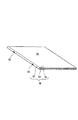
このような課題に対し、折り畳まれたシート束Sを平坦に置けるように、例えば、図8に示したシート束Saのように、背面折り部Sbの膨らみを少なくして平坦にするシート束背部処理装置がある(特許文献1参照)。 For such a problem, the sheet bundle back portion that flattens the fold of the back folding portion Sb, such as the sheet bundle Sa shown in FIG. 8, so that the folded sheet bundle S can be placed flat. There exists a processing apparatus (refer patent document 1).
従来のシート束背部処理装置を、図23乃至図25に示す。このシート束背部処理装置901は、まず、折りローラ対907から背面折り部(背表紙)Sbを先端にして矢印B方向に排出された冊子状の2つ折りの中綴じシート束Sを、昇降可能な停止板905で一旦受け止めて停止させる(図24(a))。その後、シート束背部処理装置901は、グリップ部材902,903でシート束を把持し、停止板905を上昇させる(図24(b))。このとき、背面折り部Sbは、グリップ部材902,903から突出している。停止板905は、背面折り部Sbから離れる。そして、シート束背部処理装置901は、背部処理手段の押圧部材としての押圧ローラ904を背面折り部Sbに押圧させて背面折り部Sbに沿って矢印A方向に走行させる。湾曲していた背面折り部Sbは、押圧ローラ904に押圧されて、平坦になる(図25参照)。最後に、シート束背部処理装置901は、排出ベルト対906によって処理済のシート束Sを排紙トレイ908に矢印B方向に排出して積載する(図24(c))。
A conventional sheet bundle back processing apparatus is shown in FIGS. The sheet bundle
なお、従来のシート束背部処理装置901は、単体で使用されるだけでなく、シートを束状にして折り畳むシート束折り装置とでシート束処理装置を構成し、そのシート束折り装置によって折り畳まれたシート束の背面折り部を平坦にするようになっている場合もある。
The conventional sheet bundle
さらに、シート束処理装置に組み込まれた従来のシート束背部処理装置は、シートに画像を形成する画像形成手段を備えた画像形成装置の装置本体に装備されて、画像形成装置の一部分を構成している場合もある。 Further, a conventional sheet bundle back processing apparatus incorporated in a sheet bundle processing apparatus is provided in an apparatus main body of an image forming apparatus having an image forming means for forming an image on a sheet, and constitutes a part of the image forming apparatus. Sometimes it is.
また、他の従来のシート束背部処理装置として、第1折りローラ対で折り処理された背面折り部を、第1折りローラ対とは別の第2折りローラ対で挟んで、この第2折りローラ対を背面折り部に沿って移動させることで背面折り部を強化する(背面折り部の折り目の形状を整える)ものがある。第2折りローラ対の動作時、第1折りローラ対はシート束が動かないように保持している(特許文献2参照)。 Further, as another conventional sheet bundle spine processing device, the back folding portion folded by the first folding roller pair is sandwiched by a second folding roller pair different from the first folding roller pair, and the second folding roller pair is processed. There is one that reinforces the back fold by moving the roller pair along the back fold (to adjust the shape of the fold of the back fold). During the operation of the second folding roller pair, the first folding roller pair holds the sheet bundle so as not to move (see Patent Document 2).
しかし、これら従来のシート束背部処理装置は、シート束の背面折り部を平坦にする処理と、背面折り部を強化する処理とを別々に施すようになっている。このため、1つのシート束背部処理装置で、シート束の背面折り部を平坦にする処理と、折り目を強化する処理とを選択的に行なえる装置の出現が待たれていた。 However, these conventional sheet bundle spine processing apparatuses separately perform a process for flattening the back folded part of the sheet bundle and a process for strengthening the back folded part. For this reason, the advent of an apparatus capable of selectively performing the process of flattening the back folded portion of the sheet bundle and the process of strengthening the crease with one sheet bundle back processing apparatus has been awaited.
また、このようなシート束背部処理装置を備えたシート束処理装置と画像形成装置は、使い勝手が制限されて、使い勝手が悪かった。 Further, the sheet bundle processing apparatus and the image forming apparatus provided with such a sheet bundle back part processing apparatus are limited in usability, and are not easy to use.
本発明は、1台で、背面折り部を挟圧して折り目の形状を整える処理機能と、背面折り部の背部を押圧して背部を平坦にする処理機能とを備え、各処理機能を選択してシート束を処理できるシート束背部処理装置を提供することを目的としている。 The present invention includes a processing function for adjusting the shape of the fold by clamping the back fold portion and a processing function for pressing the back portion of the back fold portion to flatten the back portion, and selects each processing function. An object of the present invention is to provide a sheet bundle back processing apparatus capable of processing a sheet bundle.
本発明は、1台で、上記各処理機能を選択してシート束を処理できるシート束背部処理装置を備えて、使いやすくしたシート束処理装置を提供することを目的としている。 An object of the present invention is to provide an easy-to-use sheet bundle processing apparatus including a sheet bundle back processing apparatus that can process a sheet bundle by selecting each of the above processing functions.
本発明は、1台で、上記各処理機能を選択してシート束を処理できるシート束背部処理装置を備えて、使いやすくした画像形成装置を提供することを目的としている。 SUMMARY OF THE INVENTION An object of the present invention is to provide an image forming apparatus that is provided with a sheet bundle back processing apparatus that can process a sheet bundle by selecting each of the above processing functions and that is easy to use.
上記目的を達成するため、本発明のシート束背部処理装置は、折り畳まれたシート束の背面折り部の表裏面を挟圧しながら移動して折り目を強化する折り目処理手段と、前記シート束の背面折り部の背部を押圧しながら移動して前記背部を平坦にする背部処理手段と、前記折り目処理手段と前記背部処理手段を選択的に作動させる制御部と、を備えている。 In order to achieve the above object, a sheet bundle back surface processing apparatus according to the present invention includes a crease processing means that moves while pinching the front and back surfaces of a folded back surface of a folded sheet bundle and reinforces the fold, and the back surface of the sheet bundle It includes a back processing means for the folded portion of the back moves while pressing to flatten the back, and a control unit for selectively actuating said back processing means and the fold processing unit.
上記目的を達成するため、本発明のシート束処理装置は、シート束を折り曲げる折り曲げ手段と、前記折り曲げ手段によって折り曲げられたシート束の背面折り部を処理するシート束背部処理装置と、を備え、前記シート束背部処理装置が上記シート束背部処理装置である。 In order to achieve the above object, a sheet bundle processing apparatus of the present invention comprises a folding means for folding a sheet bundle, and a sheet bundle back processing apparatus for processing a back folded portion of the sheet bundle folded by the folding means, The sheet bundle back processing apparatus is the sheet bundle back processing apparatus.
上記目的を達成するため、本発明の画像形成装置は、シートに画像を形成する画像形成手段と、前記画像形成手段によって画像形成されたシートを束状にして折り曲げる折り曲げ手段と、前記折り曲げ手段によって折り曲げられたシート束の背面折り部を処理するシート束背部処理装置と、を備え、前記シート束背部処理装置が上記シート束背部処理装置である。
上記目的を達成するため、本発明の画像形成装置は、シートに画像を形成する画像形成手段と、画像形成され、折り畳まれたシート束の背面折り部の表裏面を挟圧しながら移動して折り目を強化する折り目処理手段と、前記シート束の背面折り部の背部を押圧しながら移動して前記背部を平坦にする背部処理手段と、前記折り目処理手段と前記背部処理手段を選択的に作動させる制御部と、を備えている。
In order to achieve the above object, an image forming apparatus according to the present invention includes an image forming unit that forms an image on a sheet, a folding unit that folds a sheet on which an image is formed by the image forming unit, and a folding unit. A sheet bundle back processing device for processing a back folded portion of the folded sheet bundle, and the sheet bundle back processing device is the sheet bundle back processing device.
In order to achieve the above object, an image forming apparatus according to the present invention includes an image forming unit that forms an image on a sheet, and an image formed and folded sheet bundle that moves while pinching the front and back surfaces of a back folded portion of a folded sheet bundle. Fold processing means for strengthening the sheet, back processing means for flattening the back by moving while pressing the back part of the back folding part of the sheet bundle, and selectively operating the crease processing means and the back processing means And a control unit.
本発明のシート束背部処理装置は、折り目処理手段と背部処理手段との少なくとも一方を選択して作動させる選択手段を備えているので、1台の装置内でシート束の背面折り部の折り目を整える処理と、シート束背面部の背部を平坦にする処理との少なくとも1つの処理を選択することができるため、ユーザの好みに応じたシート束背部の処理を行なうことができる。また、1台の装置内で複数のシート束の背部処理が可能なため、省スペース化及び低コスト化することができる。 Since the sheet bundle back processing apparatus of the present invention includes selection means for selecting and operating at least one of the fold processing means and the back processing means, the folds of the back folds of the sheet bundle in one apparatus are provided. Since at least one of the processing for adjusting and the processing for flattening the back portion of the back side of the sheet bundle can be selected, the processing of the back portion of the sheet bundle can be performed according to the user's preference. Further, since the back portion processing of a plurality of sheet bundles can be performed in one apparatus, space saving and cost reduction can be achieved.
本発明のシート束背部処理装置は、折り目処理手段と背部処理手段との少なくとも折り目処理手段を選択して作動させる選択手段を備えているので、1台の装置内でシート束の背面折り部の折り目を整える処理と、シート束背面部の背部を平坦にする処理との少なくとも折り目を整える処理を選択することができるため、ユーザの好みに応じたシート束背部の処理を行なうことができる。また、1台の装置内で複数のシート束の背部処理が可能なため、省スペース化及び低コスト化することができる。 The sheet bundle back processing apparatus of the present invention includes selection means for selecting and operating at least the crease processing means of the fold processing means and the back processing means. Since it is possible to select at least a process for adjusting the crease between a process for adjusting the crease and a process for flattening the back part of the back side of the sheet bundle, the process for the back part of the sheet bundle can be performed according to the user's preference. Further, since the back portion processing of a plurality of sheet bundles can be performed in one apparatus, space saving and cost reduction can be achieved.
本発明のシート束処理装置は、1台の装置内でシート束の背面折り部の折り目を整える処理と、シート束背面部の背部を平坦にする処理との少なくとも1つの処理を選択することができるシート束背部処理装置を備えているので、使いやすさを向上させることができる。 The sheet bundle processing apparatus according to the present invention can select at least one of a process for adjusting the fold of the back fold portion of the sheet bundle and a process for flattening the back portion of the sheet bundle back portion in one apparatus. Since the sheet bundle back portion processing apparatus that can be used is provided, the usability can be improved.
本発明の画像形成装置は、1台の装置内でシート束の背面折り部の折り目を整える処理と、シート束背面部の背部を平坦にする処理との少なくとも折り目を整える処理を選択することができるシート束背部処理装置を備えているので、使いやすさを向上させることができる In the image forming apparatus of the present invention, it is possible to select at least a process for adjusting the crease among a process for adjusting the fold of the back fold part of the sheet bundle and a process for flattening the back part of the back part of the sheet bundle in one apparatus. Equipped with a sheet bundle back processing device that can be used to improve ease of use
以下、本発明の実施形態のシート束背部処理装置、シート束処理装置及び画像形成装置を図に基づいて説明する。 Hereinafter, a sheet bundle back processing apparatus, a sheet bundle processing apparatus, and an image forming apparatus according to an embodiment of the present invention will be described with reference to the drawings.
なお、本実施形態のシート束背部処理装置は、単体で使用されるだけでなく、シートを束状にして折り畳むシート束折り装置とでシート束処理装置を構成し、そのシート束折り装置によって折り畳まれたシート束の背面折り部を平坦にするようになっている場合もある。 The sheet bundle back processing apparatus of the present embodiment is not only used as a single unit, but also forms a sheet bundle processing apparatus with a sheet bundle folding apparatus that folds sheets in a bundle and is folded by the sheet bundle folding apparatus. In some cases, the folded back portion of the sheet bundle is flattened.
さらに、シート束処理装置に組み込まれたシート束背部処理装置は、シートに画像を形成する画像形成部を備えた画像形成装置の装置本体に装備されて、画像形成装置の一部分を構成している場合もある。 Further, the sheet bundle back processing apparatus incorporated in the sheet bundle processing apparatus is mounted on the apparatus main body of the image forming apparatus having an image forming unit for forming an image on the sheet, and constitutes a part of the image forming apparatus. In some cases.
(画像形成装置)
画像形成装置としての白黒/カラー複写機110を図21に基づいて説明する。白黒/カラー画像形成装置110は、白黒/カラー複写機(以下、単に「複写機」という)の本体100と、フィニッシャ600とを備えている。シート束処理装置としてのフィニッシャ600は、複写機の本体100に接続されて、中綴じ処理装置200と、平綴じ処理装置300と、シート束背部処理装置400とを備えている。中綴じ処理装置200と、平綴じ処理装置300は、中綴じ製本処理装置700を構成している。なお、フィニッシャ600は、オプションとして使用されることがある。このため、複写機の本体100は、単独でも使用できるようになっている。また、フィニッシャ600と本体100は、一体であってもよい。
(Image forming device)
A monochrome /
本体100内のカセット107a乃至107dから供給されたシートは、それぞれ画像形成手段としてのイエロー、マゼンタ、シアン、ブラックの感光ドラム101a乃至101d等によって、4色のトナー像が転写され、定着器111に搬送されてトナー画像を定着され、機外に排出される。
The sheets supplied from the cassettes 107 a to 107 d in the
(フィニッシャ)
図21において、複写機の本体100から排出されたシートは、フィニッシャ600に送られる。フィニッシャ600は、複写機の本体100から排出されたシートを順に取り込み、取り込んだ複数のシートを整合して1つの束に束ねる処理、束ねたシート束の後端をステイプラ301で綴じるステイプル処理、取り込んだシートの後端付近に孔をあけるパンチ処理、ソート処理、ノンソート処理、シート束を折る折処理、製本処理などの各種のシート後処理を行なうようになっている。本実施形態のフィニッシャ600は、少なくとも折り処理を行なえるようになっている。
(Finisher)
In FIG. 21, the sheet discharged from the copying machine
フィニッシャ600は、複写機110の本体100から排出されたシートを内部に導くための入口ローラ対602を有している。この入口ローラ対602の下流側には、シートを、平綴じ製本パスX、または中綴じ製本パスYに選択的に案内する切換フラッパ631を設けてある。
The
平綴じ製本パスXに導かれたシートは、搬送ローラ対603を介してバッファローラ605に向けて送られる。搬送ローラ対603とバッファローラ605は、正逆転可能になっている。搬送ローラ対603とバッファローラ605との間には、パンチユニット650を設けてある。パンチユニット650は、必要に応じて動作し、搬送されてきたシートの後端付近に孔をあけるようになっている。
The sheet guided to the flat stitch binding path X is sent toward the
バッファローラ605は、その外周に送られたシートを所定枚数積層して巻き付けられるローラである。バッファローラ605に送られたシートは、下流に配置された切換フラッパ611によって、サンプルトレイ621に積載されるか、もしくは、平綴じ処理装置300内の中間トレイ(以下、処理トレイという)330に積載される。
The
処理トレイ330上に束状に積載されたシートは、必要に応じて整合処理、ステイプル処理などが施された後、排出ローラ380a,380bによりスタックトレイ622上に排出される。処理トレイ330上に束状に積載されたシートを綴じるステイプル処理には、ステイプラ301が使用される。ステイプラ301は、シート束の角部や、背部に相当する部分を綴じるようになっている。
The sheets stacked in a bundle on the
切換フラッパ631に案内されたシートは、搬送ローラ対213によって収納ガイド220内に収納され、さらにシートの先端が昇降式の不図示のシート位置決め部材に接するまで搬送される。また、収納ガイド220の途中には、2対のステイプラ218(図21では、重なって見えるため、1つのみ図示してある)を設けてある。このステイプラ218は、それに対向するアンビル219と協働してシート束の中央を綴じるようになっている。
The sheet guided by the switching
なお、以下の各図中において、符号Seで示す部分は、ステイプラ218によってシート束を綴じた針を示している。
In each of the following drawings, a portion denoted by reference numeral Se indicates a needle that has bound the sheet bundle by the
ステイプラ218の下流には、折りローラ対226a,226bを設けてある。折りローラ対226に対向する位置には、突き出し部材225を設けてある。突き出し部材225の先端は、折りローラ対226a,226bのニップに対向している。折りローラ対226a,226bと突き出し部材225は、シート束を折り畳むシート束折り装置201を構成している。
Downstream of the
ステイプラ218で綴じたシート束を折るとき、上記不図示のシート位置決め部材が、ステイプル処理終了後にシート束のステイプル位置が折りローラ対226の中央位置(ニップ)に対向するように下降する。次に、突き出し部材225がシート束に向けて突き出ることにより、このシート束は折りローラ対226間(ニップ)に押し込まれて、折りローラ対226に挟み込まれながら搬送されて、2つ折り状に折り畳まれる。したがって、シート束は、中綴じされた冊子状になる。なお、シート束は、中綴じされないで、折り畳まれるときもある。
When the sheet bundle bound by the
冊子状の中綴じされたシート束はそのまま、突き出し部材225と製本束搬送ベルト401によって、シート束背部処理装置400に送られる。
The booklet-like saddle-stitched sheet bundle is sent as it is to the sheet bundle back
なお、図20に示すように、中綴じ製本処理装置700の制御部701は、ネットワークインターフェイス661によって、フィニッシャ600を制御するフィニッシャ制御部660に接続されて、CPU702、RAM703、ROM704等を備えている。CPU702は、フィニッシャ制御部660と信号の授受をしながら、シート束背部処理装置400、中綴じ処理装置200を制御するようになっている。RAM703は、シート束背部処理装置400、中綴じ処理装置200の処理情報等を記憶するようになっている。ROM704は、中綴じ製本装置700の制御手順等を記憶してある。シート束背部処理装置400は、I/O705によって、CPU702等に接続されている。中綴じ処理装置200と、ユーザ操作パネル1000は、通信インターフェース706を介して、CPU702等に接続されている。
As shown in FIG. 20, the
(第1実施形態のシート束背部処理装置)
(構成の説明)
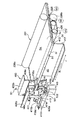
シート束背部処理装置400の構成を図1乃至図13に基づいて説明する。なお、図2に示すように、本発明において、背面折り部Sbとは、シート束Saの折り曲げられた部分の表面Sc、裏面Sd、及び背部Sfを言う。表面Scと裏面Sdは、シート束の全体の表裏面でもある。また、以下の説明において、表面を上面、裏面を下面と言う場合もある。
(Sheet bundle back portion processing apparatus of the first embodiment)
(Description of configuration)
A configuration of the sheet bundle back
図1に示すように、ストッパ417は、折り畳まれたシート束Saの先端部(背面折り部Sb)を位置決めする部材で、回転中心軸412に回動自在に支持されて、不図示のモータ、ソレノイド等駆動源により上下方向に回転するようになっている。
As shown in FIG. 1, the
図2、図3に示す、断面ほぼコの字状の筐体413は、上側プレスローラ409a、下側プレスローラ409b、平坦化ローラ410及びこれらに関連する部材を支持してユニット化されている。筐体413は、図20に示す筐体搬送モータM1によって循環する不図示の無端状のベルト、チェーン等に設けられ、そのベルト,チェーンが循環することによって、移動するようになっている。
A
なお、筐体は、図2,図3にのみ示して、他の図においては、構成を明瞭にするため、図示省略してある。 The housing is shown only in FIGS. 2 and 3 and is not shown in the other drawings for the sake of clarity.
筐体413には、上部側板405a,405bと、下部側板406a,406bとを固定してある。上部側板405aと下部側板406aとには、上下方向を向いた平坦化ローラ支点軸414を渡して回転自在に設けてある。さらに、平坦化ローラ支点軸414には、扇ギア501を設けてある。扇ギア501には、平坦化ローラ軸423を固定してある。扇ギア501には、平坦化ローラ離間モータM3によって回転するピニオン502が噛み合っている。したがって、平坦化ローラ離間モータM3が回転すると、ピニオン502と扇ギア501とが回転して、平坦化ローラ410の位置が変わるようになっている。
扇ギア501、ピニオン502、平坦化ローラ離間モータM3等は、移動手段を構成している。
The
筐体413の側板413aと上部側板405bとの間には、上側プレスローラ支点軸420aをほぼ水平に渡して回転自在設けてある。筐体413の側板413aと下部側板406bとの間には、下側プレスローラ支点軸420bをほぼ水平に渡して回転自在に設けてある。
An upper press
上側プレスローラ支点軸420aには、1対の上側プレスローラ加圧アーム418aを一体に設けてある。1対の上側プレスローラ加圧アーム418aの一端には、上側プレスローラ409aが取り付けられた上側プレスローラ軸415aをほぼ水平に、かつ回転自在に有している。上側プレスローラ409aはローラである。図4に示すように、1対の上側プレスローラ加圧アーム418aの他端と、上部側板405aとの間には(筐体413との間でもよい)、上側プレスローラ409aをシート束Sa側に付勢する上側プレスローラばね416aを設けてある。
The upper press
下側プレスローラ支点軸420bには、1対の下側プレスローラ加圧アーム418bを一体に設けてある。1対の下側プレスローラ加圧アーム418bの一端には、下側プレスローラ409bが取り付けられた下側プレスローラ軸415bをほぼ水平に、かつ回転自在に有している。下側プレスローラ409bはローラである。図4に示すように、1対の下側プレスローラ加圧アーム418bの他端と、下部側板406aとの間には(筐体413との間でもよい)、下側プレスローラ409bをシート束側に付勢する下側プレスローラばね416bを設けてある。
The lower press
挟持部材としての上、下側プレスローラ409a,409b、上、下側プレスローラばね416a,416b等は、折り目処理手段を構成している。
The upper and
したがって、1対の上側プレスローラ加圧アーム418aは、上側プレスローラ409aを有して、上側プレスローラ支点軸420aと一体に筐体413に回転自在に設けられていることになる。また、1対の下側プレスローラ加圧アーム418bも、下側プレスローラ409bを有して、下側プレスローラ支点軸420bと一体に筐体413に回転自在に設けられていることになる。よって、上側プレスローラ409aと下側プレスローラ409bは、上側プレスローラばね416aと下側プレスローラばね416bとの引っ張り力によって、シート束Saの背面折り部Sb近くのの上面Scと下面Sdとの両側から挟圧するようになっている。
Accordingly, the pair of upper press
図3に示すように、上側プレスローラ409aと下側プレスローラ409bとによるシート挟圧力は、上側、下側プレスローラ加圧アーム418a,418bに形成した複数の挟圧力調節手段としての上側、下側挟圧力調節孔419a,419bを選択して上側、下側プレスローラばね416a,416b(図6参照)の引っ掛け位置を変えて、上側、下側プレスローラばね416a,416bの長さを調節することによって調節することができる。
As shown in FIG. 3, the sheet clamping pressure by the
上部側板405aと下部側板406aとに渡して回転自在に設けてある平坦化ローラ支点軸414の両端近くには、上部平坦化ローラ加圧アーム421aと下部平坦化ローラ加圧アーム421bとを一体に設けてある。上部平坦化ローラ加圧アーム421aと下部平坦化ローラ加圧アーム421bとの一端には、上下方向を向いた回転自在な平坦化ローラ軸423によって平坦化ローラ410を設けてある。
An upper flattening
上部平坦化ローラ加圧アーム421aと下部平坦化ローラ加圧アーム421bとの他端と、上部側板405aと下部側板406aとの間には(筐体413との間でもよい)、平坦化ローラ410をシート束の背面折り部Sbに押し付ける上側平坦化ローラばね416c(図5参照)と下側平坦化ローラばね416dとを設けてある。これにより、扇ギア501と平坦化ローラ離間モータM3のピニオン502とのバックラッシュを取り除き、平坦化ローラ410の位置制御を正確に行なうことができると共に、シート束の背面折り部Sbに押し付ける力を一定以上に保つことが可能となる。
Between the other end of the upper flattening
平坦化ローラ410がシート束の背面折り部Sbを押圧する押圧力は、図3に示すように、上部平坦化ローラ加圧アーム421aと下部平坦化ローラ加圧アーム421bに形成した複数の上部押圧力調節孔424aと下部押圧力調節孔424bとを選択して上側、下側平坦化ローラばね416c,416dの引っ掛け位置を変えて、上側、下側平坦化ローラばね416c,416d(図5参照)の長さを調節することによって調節することができる。
The pressing force with which the flattening
押圧部材としての平坦化ローラ410、上側、下側平坦化ローラばね416c,416d等は、背部処理手段を構成している。
The flattening
本実施形態では、加圧ばねの伸張ストロークを変更することで、挟圧力を可変にしたが、単にばね変更での対応、または、加圧アームのアーム比率の変更等でも、同様な効果を奏する。例えば、上側、下側プレスローラばね416a,416bを筐体413に引っ掛ける位置に位置調節自在な不図示の引っ掛け板を設け、その引っ掛け位置を調節して上側、下側プレスローラばね416a,416bの長さを調節することによって上記挟圧力を調節してもよい。
In the present embodiment, the clamping pressure is made variable by changing the extension stroke of the pressure spring. However, the same effect can be obtained by simply changing the spring or changing the arm ratio of the pressure arm. . For example, a hook plate (not shown) whose position is freely adjustable is provided at a position where the upper and lower press roller springs 416a and 416b are hooked to the
また、上側プレスローラ409a、下側プレスローラ409b、および平坦化ローラ410のシート束への接触位置関係においても、冊子の枚数、冊子を構成するシートの坪量、シートの画像種類によって、可変するようにしてもよい。すなわち、図4における距離Lを調節できるようになっていてもよい。
Further, the positional relationship of the
図4に示すように、上側プレスローラ409a、下側プレスローラ409bがシート束に接触する位置は、平坦化ローラ410がシート束に接触する位置よりも距離Lだけシート束の背面折り部を平坦にするため移動するJ方向に先行している。なお、平坦化ローラ410は距離Lだけ遅れた位置に必ずしも設ける必要がない。上側プレスローラ409aと下側プレスローラ409bと同じ位置であってもよい。
As shown in FIG. 4, the position where the
以上の構成において、図20に示す筐体搬送モータM1は、筐体413を移動するようになっている。平坦化ローラ410のホームセンサS1は、図1,図2に示す位置に設けられて、平坦化ローラ410がホームポジションにいるか否かを筐体413を介して検知するようになっている。ストッパシート検知センサS2は、図5に示す位置に設けてあり、ストッパ417で受け止められたシート束の先端(背部Sf)を検知するようになっている。シート束搬送モータM2(図1,5,20参照)は、製本束搬送ベルト401を駆動するようになっている。平坦化ローラ離間モータM3(図1,4参照)は、シート束の背面折り部Sbに対する平坦化ローラ410の位置を制御するモータである。中綴じ処理装置200(図21参照)における、折りローラ駆動モータM4(図1,5,20参照)は、折りローラ226a,226bを回転駆動するようになっている。突き出し部材駆動モータM5は、突き出し部材225を往復移動するようになっている。突き出し部材位置センサS3は、図6(c)に示す位置に設けてあり、突き出し部材225が最も突き出た位置を検知するようになっている。
In the above configuration, the case transport motor M1 shown in FIG. 20 moves the
(動作の説明)
(シート束の背面折り部の強化処理(背面折り部の挟圧処理)の場合)
図6において、上側プレスローラ409a、下側プレスローラ409bは、シート束Saを把持していないとき、互いに接触しているが、図面を明瞭にするため、離間させてある。ここで、シート束折り目強化処理のみを行なう場合、平坦化ローラ410は、平坦化ローラ離間モータM3、ピニオン502、扇ギア501とにより、退避位置APに移動されている。よって、シート束背部処理装置400がR(図1)方向に移動する場合でも、シート束に接触することはない。
(Description of operation)
(In the case of strengthening processing of the back fold of the sheet bundle (clamping processing of the back fold)
In FIG. 6, an
図6(a)に示すように、中綴じされて、折りローラ対226a,226bと、突き出し部材225により、折り畳まれたシート束Saは、折りローラ対226a,226b、突き出し部材225、製本束搬送ベルト401により、ストッパ417へ搬送される。このとき、上側プレスローラ409a、下側プレスローラ409bのニップ線K(図4参照)は、シート束Saの端面よりも外側の位置にある。シート束Saの背面折り部Sbがストッパ417に突き当たる前に、図6(b)に示すように、折りローラ対226a,226bは、シート束Saから離間する。そして、製本束搬送ベルト401は、シート束Saがストッパ417に突き当たるまでシート束Saを搬送する。シート束Saの搬送方向先端部(背面折り部Sb)が、ストッパ417に突き当たると、先端の斜行が補正される。その後、図6(c)に示すように、ストッパ417は下方へ退避する。
As shown in FIG. 6A, the sheet bundle Sa which is saddle-stitched and folded by the folding roller pairs 226a and 226b and the protruding
シート束Saの先端部(背面折り部Sb)が位置決めされると図7(a)に示すようにシート束背部処理装置400が矢印J方向に移動し始める。そして、上側プレスローラ409aと下側プレスローラ409bが、シート束Saの背面折り部Sbの表裏面Sc,Sdを咥える。
When the leading end (back folding portion Sb) of the sheet bundle Sa is positioned, the sheet bundle back processing
シート束背部処理装置400がシート束Saの背面折り部Sbを強化処理している間(背面折り部Sbの折り目の形状を整えている間)、シート束Saは、先端、中間部が製本束搬送ベルト401、突き出し部材225、及び折りローラ対226a,226bに支持され、かつ後部が折りローラ対226a,226bに挟持されている。このため、シート束は、シート束背部処理装置400に引きずられることがほとんどなく、位置がほとんどずれないようになっている。なお、折りローラ対226a,226bの代わりに単なる搬送ローラ対を使用してもよい。
While the sheet bundle back processing
シート束背部処理装置400は、シート束の他端まで移動すると、シート束の背面折り部Sbの強化処理を終了する。この結果、シート束背部処理装置400は、シート束の背面折り部Sbの膨らみを少なくして折り目の形状を整えることができる。その後、図7(c)に示すように、折りローラ対226a,226bが再びシート束Saから離間する。そして、シート束背部処理装置400の背面折り部の強化処理動作中に、シート束Saが垂れ下がらないようにシート束を支持していた突き出し部材225が、折りローラ対226a,226bの後方まで退避して、次のシート束の中綴じ製本処理に備える。また、背面折り部Sbの表裏面Sc,Sdを平坦に処理されたシート束Saは、排紙トレイ480に排出されて順次積載されていく。
When the sheet bundle back
シート束背部処理装置400は、以上の一連の動作を行なうことにより、図8に示すように、背面折り部(背表紙)Sbを膨らみの少ない形状にすることができ、高品位なシート束を提供することができる。
By performing the series of operations described above, the sheet bundle back
(シート束の背面折り部の強化処理(背面折り部の挟圧処理)と背部の平坦化処理を同時に行なう場合)
図9において、上側プレスローラ409a、下側プレスローラ409bは、シート束を把持していないとき、互いに接触しているが、図面を明瞭にするため、離間させてある。ここで、シート束の背面折り部の強化処理と背部の平坦化処理を同時に行なう場合、平坦化ローラ410は、平坦化ローラ離間モータM3、ピニオン502、扇ギア501により、シート束の背部Sfに当接する位置に移動される。よって、シート束背部処理装置400がR方向(図1参照)に移動するとき、常に、平坦化ローラ410は、シート束の背部Sfに接触している。
(In case of strengthening the back folding part of the sheet bundle (clamping process of the back folding part) and flattening the back part simultaneously)
In FIG. 9, an
図9(a)に示すように、中綴じされて、折りローラ対226a,226bと、突き出し部材225により、折り畳まれたシート束Saは、折りローラ対226a,226b、突き出し部材225、製本束搬送ベルト401により、ストッパ417へ搬送される。このとき、上側プレスローラ409a、下側プレスローラ409bのニップ線K(図4参照)は、シート束Saの端面よりも外側の位置にある。シート束Saの背面折り部Sbがストッパ417に突き当たる前に、図9(b)に示すように、折りローラ対226a,226bは、シート束Saから離間する。そして、製本束搬送ベルト401は、シート束Saがストッパ417に突き当たるまでシート束Saを搬送する。シート束Saの搬送方向先端部(背面折り部Sb)が、ストッパ417に突き当たると、先端の斜行が補正される。その後、図9(c)に示すように、ストッパ417は下方へ退避する。
As shown in FIG. 9A, the sheet bundle Sa which is saddle-stitched and folded by the folding roller pairs 226a and 226b and the protruding
シート束Saの先端部が位置決めされると図10(a)に示すようにシート束背部処理装置400が矢印J方向に移動し始める。そして、上側プレスローラ409aと下側プレスローラ409bが、シート束Saの背面折り部Sbの表裏面Sc,Sdを咥える。
その後、上側プレスローラ409aと下側プレスローラ409bの後を追うようにして、距離L(図4参照)だけ遅れて平坦化ローラ410がシート束Saの背面折り部Sbの背部Sfを圧接しながら、背部Sfを平坦にしていく。
When the leading end of the sheet bundle Sa is positioned, the sheet bundle back processing
Thereafter, the flattening
シート束背部処理装置400がシート束の背面折り部の処理を行っている間、シート束は、先端、中間部が製本束搬送ベルト401、突き出し部材225、及び折りローラ対226a,226bに支持され、かつ後部が折りローラ対226a,226bに挟持されている。このため、シート束は、シート束背部処理装置400に引きずられることがほとんどなく、位置がほとんどずれないようになっている。製本束搬送ベルト401(又は、突き出し部材225)、及び折りローラ対226a,226bは、保持手段を構成している。
While the sheet bundle back
シート束背部処理装置400は、シート束の端まで移動すると、シート束の背面折り部の強化処理と背部の平坦化処理を終了する。この結果、シート束背部処理装置400は、シート束の背面折り部Sbの膨らみを少なくして折り目の形状を整えることと、背部Sfを平坦にすることができる。その後、図10(c)に示すように、折りローラ対226a,226bが再びシート束Saから離間する。そして、シート束背部処理装置400のシート束背部処理動作中に、シート束Saが垂れ下がらないようにシート束を支持していた突き出し部材225が、折りローラ対226a,226bの後方まで退避して、次のシート束の中綴じ製本処理に備える。また、背面折り部Sbの表裏面Sc,Sdと背部Sfを平坦に処理されたシート束Saは、排紙トレイ480(図21参照)に排出されて順次積載されていく。
When the sheet bundle back processing
シート束背部処理装置400は、以上の一連の動作を行なうことにより、図11に示すように、背面折り部(背表紙)Sbを膨らみの少ない角張った形状にして小さく且つ平坦に処理することが可能となり、高品位なシート束を提供することができる。
By performing the above-described series of operations, the sheet bundle back
なお、図12に示すように、必ずしも、突き出し部材225でシート束を支持する必要がない。シート束を、図12において不図示の製本束搬送ベルト401で支持して、折りローラ対226a,226bで挟持してもよい。
In addition, as shown in FIG. 12, it is not always necessary to support the sheet bundle with the protruding
以上、説明したように、本実施形態のシート束背部処理装置400は、上側、下側プレスローラ409a,409bが背面折り部の傍の上面Scと下面Sdを把持しながら走行してシート束背部の折り目を強化(膨らみを少なく)する処理と、上側、下側プレスローラ409a,409bが背面折り部の傍の上面Scと下面Sdを把持しながら走行するのにともなって、平坦化ローラ410も走行して上側、下側プレスローラ409a,409bが把持している両面近傍のシート束の背部Sfを平坦にする(角張った形状にする)処理とを選択的に行なうことができるようになっている。
As described above, the sheet bundle
この処理の選択は、図13に示すユーザ操作パネル1000により、『背面折り部強化』ボタン1001と『背部平坦化』ボタン1002とのいずれかをユーザが好みに応じて選択することによって行われる。
This process is selected by the user selecting one of the “enhance back folding part”
『背面折り部強化』ボタン1001を選択すると、図20に示す中綴じ製本装置制御部701が、平坦化ローラ離間モータM3を作動させて、平坦化ローラ410がシート束の背面折り部Sbに接触しない退避位置AP(図6(a)参照)に移動させる。その後、筐体モータM1(図20参照)を作動させる。この結果、シート束背部処理装置400がシート束の背面折り曲げ部Sbに沿って移動して、背面折り部強化処理を行なう。
When the “enhance back folding part”
『背部平坦化』ボタン1002を選択すると、図20に示す中綴じ製本装置制御部701が、平坦化ローラ離間モータM3を作動させて、平坦化ローラ410が退避位置AP(図6(a)参照)からシート束の背面折り部Sbに接触可能な押圧位置に移動させる。その後、筐体搬送モータM1(図20参照)を作動させる。この結果、シート束背部処理装置400がシート束の背面折り曲げ部Sbに沿って移動して、背面折り部強化処理と背部平坦化処理を行なう。
When the “back flattening”
さらに、ユーザが『最適処理』ボタン1003を選択すると、図20に示す中綴じ製本装置制御部701が、シート束の厚さが厚い場合(例えば10mm以上)、背面折り部強化処理と背部平坦化処理を選択し、シート束厚さが薄い場合(例えば10mm未満)、背面折り部強化処理のみを選択して、シート束背部処理装置400に各処理を行なわせる。
Further, when the user selects the “optimum processing”
ユーザ操作パネル1000、中綴じ製本装置制御部701等は、選択手段を構成している。
The
このように、本実施形態のシート束背部処理装置400は、従来、別々の装置でしか行なえなかったシート束の処理を1台で行なうことができる。しかも、ユーザが処理を選択することができるようになっている。さらに、シート束の厚みに応じて、自動的にシート束に最適な処理を選択することができるようになっている。
As described above, the sheet bundle back
(第2実施形態のシート束背部処理装置)
以上の第1実施形態のシート束背部処理装置400は、ストッパ417でシート束を受け止める位置が一箇所である。このため、平坦化ローラ410が筐体413に対して移動するようになっている。すなわち、シート束の背面折り部を強化処理する他に、背部の平坦化処理も同時に行なうときには、平坦化ローラ410は、扇ギア501、ピニオン502、及び平坦化ローラ離間ローラM3によって、上記一箇所の位置に移動して、シート束Saの背部Sbに当接できる位置で待機するようになっている。また、シート束の背面折り部の強化処理のみ行い背部の平坦化処理を行なわないときには、平坦化ローラ410は、上記一箇所の位置から、シート束Saの背部Sbに当接しない退避位置AP(図6(a)参照)に退避している。
(Sheet Bundle Back Processing Device of Second Embodiment)
In the sheet bundle back
これに対して、図14乃至図18に示す第2実施形態のシート束背部処理装置1400は、ストッパ417がソレノイド601(モータでも可)によってシート搬送方向の第1の位置と、第2の位置とに移動するようになっており、シート束を受け止める位置が2箇所ある。このため、平坦化ローラ410は筐体413に対して移動しないようになっている。
On the other hand, in the sheet bundle
第1の位置は、背部の平坦化処理を行なわないでシート束の背面折り部の強化処理のみ行なうときの位置であり、上記一箇所の位置に相当する位置である。第2の位置は、シート束の背面折り部を強化処理する他に、背部の平坦化処理も同時に行なうときの位置であり、第1の位置よりも下流側である。すなわち、上記退避位置APにいる平坦化ローラ410よりやや下流側の上記退避位置APに相当する位置である。
The first position is a position when only the reinforcing process of the back folded portion of the sheet bundle is performed without performing the flattening process of the back, and is a position corresponding to the one position. The second position is a position when the back-folding process of the sheet bundle is strengthened and the flattening process of the back part is performed at the same time, and is downstream of the first position. That is, it is a position corresponding to the retreat position AP slightly downstream of the flattening
このように、第2実施形態のシート束背部処理装置1400は、第1実施形態のシート束背部処理装置400における扇ギア501、ピニオン502、及び平坦化ローラ離間ローラM3を省略して、平坦化ローラ410の位置に合わせて、シート束の背部の平坦化処理を行なうようになっている。
As described above, the sheet bundle back
なお、第1実施形態のシート束背部処理装置400と同一部分については、同一符号を付して、一部説明を省略する。
In addition, about the same part as the sheet | seat bundle back
(動作の説明)
(シート束の背面折り部の強化処理(背面折り部の挟圧処理)の場合)
この処理動作は、第1実施形態のシート束背部処理装置400における、図6、図7に示す動作と同様であるので概略説明する。図15、図16において、中綴じされて、折りローラ対226a,226bと、突き出し部材225により、折り畳まれたシート束Saは、折りローラ対226a,226b、突き出し部材225、製本束搬送ベルト401により、ストッパ417へ搬送されて、ストッパ417に受け止められる。このときのストッパ417の位置は、上記第1の位置にいる。その後、図15(c)に示すように、ストッパ417が下方へ退避する。シート束Saの背面折り部Sbと平坦化ローラ410との間に一定の距離Tが確保されている。
(Description of operation)
(In the case of strengthening processing of the back fold of the sheet bundle (clamping processing of the back fold)
Since this processing operation is the same as the operation shown in FIGS. 6 and 7 in the sheet bundle
シート束Saの先端部が位置決めされると図16(a)、(b)に示すようにシート束背部処理装置1400が矢印J方向に移動し始めて、上側プレスローラ409aと下側プレスローラ409bで、シート束Saの背表紙部の上下面を咥える。
When the leading end of the sheet bundle Sa is positioned, as shown in FIGS. 16A and 16B, the sheet bundle
そして、シート束背部処理装置1400は、シート束の他端まで移動する。この間、シート束Saの背面折り部Sbと平坦化ローラ410との間に一定の距離Tが確保されているので、平坦化ローラ410は、シート束の背部Sfに接触することがない。したがって、シート束背部折り部強化処理のみ行なわれる。
Then, the sheet bundle back
その後、図16(c)に示すように、折りローラ対226a,226bが再びシート束Saから離間する。その後、突き出し部材225が、折りローラ対226a,226bの後方まで退避して、次のシート束の中綴じ製本処理に備える。また、背面折り部の強化処理されたシート束Saは、排紙トレイ480に排出されて順次積載されていく。
Thereafter, as shown in FIG. 16C, the pair of
シート束背部処理装置1400は、以上の一連の動作を行なうことにより、図8に示すように、背面折り部(背表紙)Sbを膨らみの少ない形状にすることができ、高品位なシート束を提供することができる。
By performing the above-described series of operations, the sheet bundle back
(シート束の背面折り部の強化処理(背面折り部の挟圧処理)と背部の平坦化処理を同時に行なう場合)
この処理動作も、第1実施形態のシート束背部処理装置400における、図9、図10に示す動作と同様であるので概略説明する。図17、図18において、中綴じされて、折りローラ対226a,226bと、突き出し部材225により、折り畳まれたシート束Saは、折りローラ対226a,226b、突き出し部材225、製本束搬送ベルト401により、ストッパ417へ搬送される。このとき、ソレノイド601をONにすることにより、ストッパ417は、平坦化モード待機ポジションPHに移動されて、シート束Saの背面折り部Sbを受け止めるまで待機している。
(In case of strengthening the back folding part of the sheet bundle (clamping process of the back folding part) and flattening the back part simultaneously)
Since this processing operation is also the same as the operation shown in FIGS. 9 and 10 in the sheet bundle back
シート束Saの先端部が位置決めされると図18(a)、(b)に示すようにシート束背部処理装置1400が矢印J方向に移動し始める。そして、上側プレスローラ409aと下側プレスローラ409bが、シート束Saの背表紙部の上下面を咥え始める。
When the leading end of the sheet bundle Sa is positioned, the sheet bundle back
その後、上側プレスローラ409aと下側プレスローラ409bの後を追うようにして、図4に示す距離Lに相当する距離だけ遅れて平坦化ローラ410がシート束Saの背面折り部Sbに沿って移動する。この間、上側プレスローラ409aと下側プレスローラ409bがシート束の背部折り部の強化処理を行なってシート束の折り目を確実に折り曲げた形状にする。平坦化ローラ410が背部の平坦化処理を行なって背部Sfを平坦にする。
Thereafter, the flattening
シート束背部処理装置1400は、シート束の端まで移動すると、シート束背部折り目強化及び平坦化処理を終了する。その後、図18(c)に示すように、折りローラ対226a,226bが再びシート束Saから離間する。その後、突き出し部材225が、折りローラ対226a,226bの後方まで退避して、次のシート束の中綴じ製本処理に備える。また、背面折り部を平坦に処理されたシート束Saは、排紙トレイ480に排出されて順次積載されていく。
When the sheet bundle back
シート束背部処理装置1400は、以上の一連の動作を行なうことにより、図11に示すように、背面折り部(背表紙)Sbを膨らみの少ない角張った形状にして小さく且つ平坦に処理することが可能となり、高品位なシート束を提供することができる。
By performing the above-described series of operations, the sheet bundle back
以上説明したように、第2実施形態のシート束背部処理装置1400は、ソレノイド601をON/OFFすることにより、ストッパ417の待機位置を変更することにより、シート束Saの背面折り部Sbの平坦化ローラに対する離接を行なうようになっている。
As described above, the sheet bundle back
このため、シート束背部処理装置1400は、シート束Saの背面折り部Sbの強化処理を行ないたい場合、シート束背部を平坦化ローラ410に当接させない位置に停止させて、上側、下側プレスローラ409a,409bが背面折り部の傍の上面Scと下面Sdを把持しながら走行してシート束の折り目を確実に折った形状にすることができる。
For this reason, when the sheet bundle back
また、シート束背部処理装置1400は、シート束背部に平坦化処理を施したい場合、シート束背部を平坦化ローラ410に当接させる位置に停止させて、上側、下側プレスローラ409a,409bが背面折り部の傍の上面Scと下面Sdを把持しながら走行するとともに、平坦化ローラ410も上側、下側プレスローラ409a,409bが把持している両面Sc,Sd近傍の背部Sfを押圧しながら走行する。
Further, when the sheet bundle back
また、本実施形態のシート束背部処理装置1400は、第1実施形態のシート束背部処理装置400と同様に、図13に示すユーザ操作パネル1000により、『背面折り部強化』ボタン1001と『背部平坦化』ボタン1002とのいずれかをユーザが好みに応じて選択することによって行われる。さらに、ユーザが『最適処理』ボタン1003を選択すると、本実施形態のシート束背部処理装置400は、シート束の厚さが厚い場合(例えば10mm以上)、背面折り部強化処理と背部平坦化処理とを行い、シート束厚さが薄い場合(例えば10mm未満)、背面折り部強化処理のみを、自動的に行なうようになっている。
Similarly to the sheet bundle back
このように、本実施形態のシート束背部処理装置1400も、従来、別々の装置でしか行なえなかったシート束の処理を1台で行なうことができる。しかも、ユーザが処理を選択することができるようになっている。さらに、シート束の厚みに応じて、自動的にシート束に最適な処理を選択することができるようになっている。
As described above, the sheet bundle back
以上の第1、第2実施形態のシート束背部処理装置400,1400は、綴じられたシート束の背面折り部の強化処理、または、平坦化処理を行なうようになっているが、綴じられていないシート束であっても同様の処理を施すことができる。
The sheet bundle back processing
また、以上説明した、挟圧部材としての各プレスローラ409aないし409bは、ローラであるが、必ずしもローラである必要はない。無端状の循環自在なベルト、へら状の部材であってもよい。また、押圧部材としての平坦化ローラ410も、必ずしもローラである必要はない。無端状の循環自在なベルト、へら状の部材であってもよい。
Further, the
また、挟圧部材のプレスローラ409a及び409bをモータM6や不図示のソレノイドの駆動源によって作動する図19に示すプレスローラ離間機構801のカム802により離間させ、シート束に接触させずに、平坦化ローラ410のみをシート束背部に接触させることにより、シート束の背面折り部の強化処理(背面折り部の挟圧処理)と背部の平坦化処理とのいずれか一方の処理と、両方の処理とを選択的に行なうことも可能である。プレスローラ離間機構801のカム802は、図13に示すようなユーザ操作パネルにより、『背部平坦化』ボタンを押されたとき作動するようになっている。この場合の選択手段は、ユーザ操作パネル、中綴じ製本処理装置の制御部701(図20参照)、及びプレスローラ離間機構801等で構成されている。
Further, the
AP 平坦化ローラの退避位置
Sa シート束
Sb シート束の背面折り部
Sc シート束の上面(表面)
Sd シート束の下面(裏面)
Se 綴じた針
Sf 背部
M3 平坦化ローラ離間モータ(移動手段)
100 白黒/カラー複写機の本体(画像形成装置の本体)
101a乃至101d 感光ドラム(画像形成手段)
110 白黒/カラー複写機(画像形成装置)
200 中綴じ処理装置
201 シート束折り装置
300 平綴じ処理装置
400 第1実施形態のシート束背部処理装置
409a 上側プレスローラ(折り目処理手段、挟持部材)
409b 下側プレスローラ(折り目処理手段、挟持部材)
410 平坦化ローラ(背部処理手段、押圧手段)
413 筐体
416a 上側プレスローラばね(折り目処理手段)
416b 下側プレスローラばね(折り目処理手段)
416c 上側平坦化ローラばね(背部処理手段)
416d 下側平坦化ローラばね(背部処理手段)
417 ストッパ
501 扇ギア(移動手段)
502 ピニオン(移動手段)
600 フィニッシャ(シート束処理装置)
660 フィニッシャ制御部
700 中綴じ製本処理装置
701 中綴じ製本処理装置の制御部(選択手段)
702 CPU
801 プレスローラ離間機構(選択手段)
802 カム(選択手段)
1000 ユーザ操作パネル(選択手段)
1001 『背面折り部強化』ボタン
1002 『背部平坦化』ボタン
1003 『最適処理』ボタン
1400 第2実施形態のシート束背部処理装置
AP Retraction position of the flattening roller Sa Sheet bundle Sb Back folded portion of the sheet bundle Sc Upper surface (front surface) of the sheet bundle
Sd Lower side (back side) of sheet bundle
Se Stitched needle Sf Back M3 Flattening roller separation motor (moving means)
100 B / W / color copier body (image forming device body)
101a to 101d Photosensitive drum (image forming means)
110 B / W / color copier (image forming device)
DESCRIPTION OF
409b Lower press roller (fold processing means, clamping member)
410 Flattening roller (back processing means, pressing means)
413
416b Lower press roller spring (crease processing means)
416c Upper flattening roller spring (back processing means)
416d Lower flattening roller spring (back processing means)
417
502 Pinion (moving means)
600 Finisher (sheet bundle processing device)
660
702 CPU
801 Press roller separation mechanism (selection means)
802 Cam (selection means)
1000 User operation panel (selection means)
1001 “Reinforcement of folded back part”
Claims (16)
前記シート束の背面折り部の背部を押圧しながら移動して前記背部を平坦にする背部処理手段と、
前記折り目処理手段と前記背部処理手段を選択的に作動させる制御部と、
を備えたことを特徴とするシート束背部処理装置。 A crease processing means for reinforcing the fold by moving while sandwiching the front and back surfaces of the folded back portion of the folded sheet bundle;
Back processing means that moves while pressing the back of the back folded portion of the sheet bundle to flatten the back,
A control unit for selectively actuating said back processing means and the fold processing unit,
A sheet bundle back portion processing apparatus comprising:
前記背部処理手段が、前記背面折り部の背部を押圧して、前記背面折り部に沿って移動可能な押圧部材を有していることを特徴とする請求項1に記載のシート束背部処理装置。 The crease processing means has a pair of clamping members that can move along the back fold by clamping the front and back surfaces of the back fold.
The sheet bundle back processing apparatus according to claim 1, wherein the back processing unit includes a pressing member that presses a back of the back folding unit and is movable along the back folding unit. .
前記制御部が、前記背部処理手段を作動させるとき、前記移動手段が、前記押圧部材を前記退避位置から前記押圧位置に移動させることを特徴とする請求項2又は3に記載のシート束背部処理装置。 Moving means for moving the pressing member to a pressing position for pressing a back portion of the back folding portion and a retracted position retracted from the pressing position;
4. The sheet bundle back processing according to claim 2, wherein when the control unit operates the back processing unit, the moving unit moves the pressing member from the retracted position to the pressing position. 5. apparatus.
前記折り曲げ手段によって折り曲げられたシート束の背面折り部を処理するシート束背部処理装置と、を備え、
前記シート束背部処理装置が請求項1乃至6のいずれか1項に記載のシート束背部処理装置であることを特徴とするシート束処理装置。 Folding means for folding the sheet bundle;
A sheet bundle back processing device for processing a back folded portion of the sheet bundle folded by the folding means,
The sheet bundle back processing apparatus according to any one of claims 1 to 6, wherein the sheet bundle back processing apparatus is the sheet bundle back processing apparatus.
前記画像形成手段によって画像形成されたシートを束状にして折り曲げる折り曲げ手段と、
前記折り曲げ手段によって折り曲げられたシート束の背面折り部を処理するシート束背部処理装置と、を備え、
前記シート束背部処理装置が請求項1乃至6のいずれか1項に記載のシート束背部処理装置であることを特徴とする画像形成装置。 Image forming means for forming an image on a sheet;
Folding means for folding the sheets imaged by the image forming means in a bundle; and
A sheet bundle back processing device for processing a back folded portion of the sheet bundle folded by the folding means,
An image forming apparatus, wherein the sheet bundle back processing apparatus is the sheet bundle back processing apparatus according to claim 1.
前記画像形成手段によって画像形成され、折り畳まれたシート束の背面折り部を処理するシート束処理装置と、を備え、
前記シート束処理装置が請求項7に記載のシート束処理装置であることを特徴とする画像形成装置。 Image forming means for forming an image on a sheet;
A sheet bundle processing device that processes the back folded portion of the sheet bundle that has been image-formed and folded by the image forming means,
An image forming apparatus, wherein the sheet bundle processing apparatus is the sheet bundle processing apparatus according to claim 7.
画像形成され、折り畳まれたシート束の背面折り部の表裏面を挟圧しながら移動して折り目を強化する折り目処理手段と、A crease processing means for strengthening the crease by moving while pinching the front and back surfaces of the back fold portion of the image-formed and folded sheet bundle,
前記シート束の背面折り部の背部を押圧しながら移動して前記背部を平坦にする背部処理手段と、Back processing means that moves while pressing the back of the back folded portion of the sheet bundle to flatten the back,
前記折り目処理手段と前記背部処理手段を選択的に作動させる制御部と、A controller that selectively activates the fold processing means and the back processing means;
を備えたことを特徴とする画像形成装置。An image forming apparatus comprising:
前記背部処理手段が、前記背面折り部の背部を押圧して、前記背面折り部に沿って移動可能な押圧部材を有していることを特徴とする請求項10に記載の画像形成装置。The image forming apparatus according to claim 10, wherein the back processing unit includes a pressing member that presses a back portion of the back folding portion and is movable along the back folding portion.
前記制御部が、前記背部処理手段を作動させるとき、前記移動手段が、前記押圧部材を前記退避位置から前記押圧位置に移動させることを特徴とする請求項11又は12に記載の画像形成装置。13. The image forming apparatus according to claim 11, wherein when the control unit operates the back processing unit, the moving unit moves the pressing member from the retracted position to the pressing position.
前記折り曲げ手段によって折り曲げられたシート束の背面折り部を処理するシート束背部処理装置と、を備え、A sheet bundle back processing device for processing a back folded portion of the sheet bundle folded by the folding means,
前記シート束背部処理装置が請求項10乃至15のいずれか1項に記載のシート束背部処理装置であることを特徴とする画像形成装置。16. The image forming apparatus according to claim 10, wherein the sheet bundle back portion processing apparatus is the sheet bundle back portion processing apparatus according to claim 10.
Priority Applications (2)
| Application Number | Priority Date | Filing Date | Title |
|---|---|---|---|
| JP2005147353A JP4448059B2 (en) | 2005-05-19 | 2005-05-19 | Sheet bundle back processing apparatus, sheet bundle processing apparatus, and image forming apparatus |
| US11/435,600 US7607650B2 (en) | 2005-05-19 | 2006-05-17 | Sheet-bundle spine treatment apparatus, sheet-bundle treatment apparatus, and image-forming apparatus |
Applications Claiming Priority (1)
| Application Number | Priority Date | Filing Date | Title |
|---|---|---|---|
| JP2005147353A JP4448059B2 (en) | 2005-05-19 | 2005-05-19 | Sheet bundle back processing apparatus, sheet bundle processing apparatus, and image forming apparatus |
Publications (3)
| Publication Number | Publication Date |
|---|---|
| JP2006321622A JP2006321622A (en) | 2006-11-30 |
| JP2006321622A5 JP2006321622A5 (en) | 2008-12-04 |
| JP4448059B2 true JP4448059B2 (en) | 2010-04-07 |
Family
ID=37448438
Family Applications (1)
| Application Number | Title | Priority Date | Filing Date |
|---|---|---|---|
| JP2005147353A Active JP4448059B2 (en) | 2005-05-19 | 2005-05-19 | Sheet bundle back processing apparatus, sheet bundle processing apparatus, and image forming apparatus |
Country Status (2)
| Country | Link |
|---|---|
| US (1) | US7607650B2 (en) |
| JP (1) | JP4448059B2 (en) |
Cited By (1)
| Publication number | Priority date | Publication date | Assignee | Title |
|---|---|---|---|---|
| US9221648B2 (en) | 2013-08-12 | 2015-12-29 | Ricoh Company, Limited | Sheet processing device, image forming system, and method of additionally folding sheet bundle |
Families Citing this family (41)
| Publication number | Priority date | Publication date | Assignee | Title |
|---|---|---|---|---|
| JP4724508B2 (en) * | 2005-09-13 | 2011-07-13 | キヤノン株式会社 | Sheet processing apparatus and image forming apparatus |
| JP4923538B2 (en) * | 2005-11-25 | 2012-04-25 | 富士ゼロックス株式会社 | Paper processing device |
| JP4721463B2 (en) * | 2007-02-02 | 2011-07-13 | キヤノン株式会社 | Sheet processing apparatus and image forming apparatus having the same |
| US7850156B2 (en) * | 2007-06-19 | 2010-12-14 | Kabushiki Kaisha Toshiba | Sheet finisher, image forming apparatus using the same, and sheet finishing method |
| JP5072484B2 (en) | 2007-08-20 | 2012-11-14 | キヤノン株式会社 | Bookbinding apparatus, control method therefor, and program |
| JP4991444B2 (en) | 2007-08-20 | 2012-08-01 | キヤノン株式会社 | Bookbinding apparatus, control method therefor, program, bookbinding system, and control apparatus |
| US7798950B2 (en) * | 2007-11-27 | 2010-09-21 | Ricoh Company, Limited | Sheet finisher, image forming apparatus, and sheet processing method |
| JP5094354B2 (en) * | 2007-12-07 | 2012-12-12 | キヤノン株式会社 | Sheet processing apparatus, image forming apparatus, and image forming system |
| JP4869215B2 (en) * | 2007-12-13 | 2012-02-08 | 株式会社リコー | Sheet folding apparatus, sheet conveying apparatus, sheet processing apparatus, and image forming apparatus |
| JP5070115B2 (en) * | 2008-04-15 | 2012-11-07 | 株式会社リコー | Sheet folding apparatus, sheet processing apparatus, and image forming apparatus |
| JP5245533B2 (en) * | 2008-05-16 | 2013-07-24 | 富士ゼロックス株式会社 | Sheet processing apparatus and image forming system |
| WO2010013440A1 (en) * | 2008-07-31 | 2010-02-04 | 株式会社デュプロ | Book molding device and book molding method |
| JP5197237B2 (en) * | 2008-08-29 | 2013-05-15 | キヤノン株式会社 | Sheet processing apparatus and image forming apparatus |
| EP2165847B1 (en) * | 2008-09-23 | 2016-02-10 | Müller Martini Holding AG | Device and method for manufacturing printed products |
| US8814773B2 (en) * | 2009-05-29 | 2014-08-26 | Xerox Corporation | Booklet maker with crease roller |
| JP5413075B2 (en) * | 2009-09-14 | 2014-02-12 | 株式会社リコー | Rear processing apparatus and bookbinding system |
| JP5465139B2 (en) * | 2009-10-07 | 2014-04-09 | キヤノン株式会社 | Sheet processing apparatus and image forming system |
| JP4977771B2 (en) * | 2009-10-16 | 2012-07-18 | 株式会社リコー | Bookbinding system |
| JP5168262B2 (en) * | 2009-10-30 | 2013-03-21 | 株式会社リコー | Back surface forming apparatus, image forming system, and back surface forming method |
| JP5669565B2 (en) * | 2010-01-18 | 2015-02-12 | キヤノン株式会社 | Sheet processing apparatus and image forming system |
| JP5178776B2 (en) * | 2010-05-17 | 2013-04-10 | キヤノン株式会社 | Sheet processing apparatus and image forming apparatus |
| JP5574817B2 (en) * | 2010-05-17 | 2014-08-20 | キヤノン株式会社 | Sheet processing apparatus and image forming apparatus |
| JP2012006761A (en) * | 2010-06-28 | 2012-01-12 | Ricoh Co Ltd | Sheet folding device, sheet processing device, image forming device and sheet folding method |
| JP5477251B2 (en) * | 2010-10-08 | 2014-04-23 | 株式会社リコー | Booklet processing apparatus, image forming system, and booklet processing method |
| JP5549529B2 (en) * | 2010-10-20 | 2014-07-16 | 株式会社リコー | Paper folding apparatus and image forming apparatus |
| JP5569341B2 (en) * | 2010-11-02 | 2014-08-13 | 株式会社リコー | Paper processing device |
| JP5553003B2 (en) * | 2010-11-05 | 2014-07-16 | 株式会社リコー | Paper processing device |
| JP5569356B2 (en) * | 2010-11-18 | 2014-08-13 | 株式会社リコー | Paper processing device |
| JP5675308B2 (en) * | 2010-12-07 | 2015-02-25 | キヤノン株式会社 | Sheet processing device |
| EP2634125B1 (en) * | 2012-03-01 | 2014-08-06 | SDD Holding B.V. | Device for folding a stack of sheets |
| JP6146650B2 (en) * | 2013-01-28 | 2017-06-14 | 株式会社リコー | Sheet processing apparatus and image forming system |
| JP5546652B2 (en) * | 2013-01-31 | 2014-07-09 | キヤノン株式会社 | Image forming system and image forming apparatus |
| JP6167765B2 (en) * | 2013-08-29 | 2017-07-26 | 株式会社リコー | Sheet processing apparatus, image forming system, and sheet bundle additional folding method |
| CN103754668B (en) * | 2013-12-16 | 2015-12-23 | 安徽华印机电股份有限公司 | Books roller lifting apparatus |
| JP6293475B2 (en) * | 2013-12-20 | 2018-03-14 | キヤノンファインテックニスカ株式会社 | Sheet folding apparatus and image forming apparatus using the same |
| JP6360368B2 (en) * | 2014-06-30 | 2018-07-18 | キヤノンファインテックニスカ株式会社 | Sheet processing apparatus, image forming apparatus including the same, and sheet additional folding method |
| JP5999160B2 (en) * | 2014-10-02 | 2016-09-28 | 富士ゼロックス株式会社 | Paper processing apparatus, image forming system, and rotating member pair |
| JP6406985B2 (en) * | 2014-11-19 | 2018-10-17 | キヤノン株式会社 | Sheet processing apparatus and image forming system |
| US10625971B2 (en) | 2016-01-29 | 2020-04-21 | Canon Finetech Nisca Inc. | Apparatus for processing sheets, apparatus for forming images and method of pressing folds of sheets |
| CN107324123B (en) * | 2017-06-27 | 2019-06-25 | 台聪 | A kind of medical absorbent cloth auto-folder equipment |
| CN108515785B (en) * | 2018-03-27 | 2019-07-09 | 安徽芜湖新华印务有限责任公司 | A kind of spine shaping equipment |
Family Cites Families (8)
| Publication number | Priority date | Publication date | Assignee | Title |
|---|---|---|---|---|
| US2066620A (en) * | 1935-02-25 | 1937-01-05 | Curtis Publishing Company | Book and method of making same |
| US2088904A (en) * | 1935-12-11 | 1937-08-03 | Curtis Publishing Company | Method of binding books |
| GB0005333D0 (en) * | 2000-03-07 | 2000-04-26 | Watkiss Automation Ltd | Methods of and apparatus for producing booklets |
| SE519617C2 (en) * | 2001-07-19 | 2003-03-18 | Plockmatic Int Ab | Apparatus and means for providing square and folded booklets with square spines |
| JP3918545B2 (en) | 2001-12-13 | 2007-05-23 | コニカミノルタホールディングス株式会社 | Paper post-processing method and paper post-processing apparatus |
| JP4541906B2 (en) * | 2004-01-27 | 2010-09-08 | キヤノン株式会社 | Sheet bundle back folding unit flat processing apparatus, sheet processing apparatus, and image forming apparatus |
| JP4217640B2 (en) * | 2004-02-27 | 2009-02-04 | キヤノン株式会社 | Sheet bundle back folding unit flat processing apparatus, sheet bundle processing apparatus, and image forming apparatus |
| JP2005349521A (en) * | 2004-06-10 | 2005-12-22 | Konica Minolta Business Technologies Inc | Post-processing device and image forming device |
-
2005
- 2005-05-19 JP JP2005147353A patent/JP4448059B2/en active Active
-
2006
- 2006-05-17 US US11/435,600 patent/US7607650B2/en active Active
Cited By (1)
| Publication number | Priority date | Publication date | Assignee | Title |
|---|---|---|---|---|
| US9221648B2 (en) | 2013-08-12 | 2015-12-29 | Ricoh Company, Limited | Sheet processing device, image forming system, and method of additionally folding sheet bundle |
Also Published As
| Publication number | Publication date |
|---|---|
| US20060263174A1 (en) | 2006-11-23 |
| JP2006321622A (en) | 2006-11-30 |
| US7607650B2 (en) | 2009-10-27 |
Similar Documents
| Publication | Publication Date | Title |
|---|---|---|
| JP4448059B2 (en) | Sheet bundle back processing apparatus, sheet bundle processing apparatus, and image forming apparatus | |
| JP4217640B2 (en) | Sheet bundle back folding unit flat processing apparatus, sheet bundle processing apparatus, and image forming apparatus | |
| US8109497B2 (en) | Sheet post-processing apparatus | |
| JP4663571B2 (en) | Sheet stacking apparatus, sheet processing apparatus, and image forming apparatus | |
| JP4724508B2 (en) | Sheet processing apparatus and image forming apparatus | |
| US8146905B2 (en) | Sheet finisher, image forming apparatus using the same, and sheet finishing method | |
| JP6274768B2 (en) | Sheet bundle binding processing apparatus and image forming system provided with the same | |
| US8459630B2 (en) | Sheet processing apparatus and image forming apparatus | |
| JP6360368B2 (en) | Sheet processing apparatus, image forming apparatus including the same, and sheet additional folding method | |
| JP2003267622A (en) | Sheet post-treatment device, and image forming device | |
| JP2015020339A5 (en) | ||
| JP2012201462A (en) | Sheet processing device | |
| US8382089B2 (en) | Sheet cutting apparatus and sheet post-processing apparatus having the same, and image forming system | |
| JP5896700B2 (en) | Sheet post-processing device | |
| US20140062003A1 (en) | Sheet processing apparatus, method for using the same image and image forming system | |
| JP7215291B2 (en) | Additional folding device, post-processing device, and image forming system | |
| JP5640757B2 (en) | Sheet folding apparatus and image forming system | |
| JP6282416B2 (en) | Sheet processing device | |
| JP4719637B2 (en) | Sheet processing apparatus and image forming apparatus | |
| JP5422806B2 (en) | Booklet forming apparatus and booklet forming method | |
| JP5879835B2 (en) | Sheet folding apparatus and image forming system | |
| JP2014172673A (en) | Sheet processing device, sheet processing method and bookbinding booklet | |
| JP6217229B2 (en) | Sheet processing apparatus, image forming system, and sheet bundle additional folding method | |
| JP5747634B2 (en) | Paper post-processing device | |
| JP4921193B2 (en) | Sheet post-processing device |
Legal Events
| Date | Code | Title | Description |
|---|---|---|---|
| A521 | Request for written amendment filed |
Free format text: JAPANESE INTERMEDIATE CODE: A523 Effective date: 20080515 |
|
| A621 | Written request for application examination |
Free format text: JAPANESE INTERMEDIATE CODE: A621 Effective date: 20080515 |
|
| A521 | Request for written amendment filed |
Free format text: JAPANESE INTERMEDIATE CODE: A523 Effective date: 20081021 |
|
| A977 | Report on retrieval |
Free format text: JAPANESE INTERMEDIATE CODE: A971007 Effective date: 20100114 |
|
| TRDD | Decision of grant or rejection written | ||
| A01 | Written decision to grant a patent or to grant a registration (utility model) |
Free format text: JAPANESE INTERMEDIATE CODE: A01 Effective date: 20100119 |
|
| A01 | Written decision to grant a patent or to grant a registration (utility model) |
Free format text: JAPANESE INTERMEDIATE CODE: A01 |
|
| A61 | First payment of annual fees (during grant procedure) |
Free format text: JAPANESE INTERMEDIATE CODE: A61 Effective date: 20100121 |
|
| FPAY | Renewal fee payment (event date is renewal date of database) |
Free format text: PAYMENT UNTIL: 20130129 Year of fee payment: 3 |
|
| R150 | Certificate of patent or registration of utility model |
Ref document number: 4448059 Country of ref document: JP Free format text: JAPANESE INTERMEDIATE CODE: R150 Free format text: JAPANESE INTERMEDIATE CODE: R150 |
|
| FPAY | Renewal fee payment (event date is renewal date of database) |
Free format text: PAYMENT UNTIL: 20140129 Year of fee payment: 4 |