JP4447949B2 - Method for initializing positioning apparatus, exposure apparatus and device manufacturing method - Google Patents
Method for initializing positioning apparatus, exposure apparatus and device manufacturing method Download PDFInfo
- Publication number
- JP4447949B2 JP4447949B2 JP2004089502A JP2004089502A JP4447949B2 JP 4447949 B2 JP4447949 B2 JP 4447949B2 JP 2004089502 A JP2004089502 A JP 2004089502A JP 2004089502 A JP2004089502 A JP 2004089502A JP 4447949 B2 JP4447949 B2 JP 4447949B2
- Authority
- JP
- Japan
- Prior art keywords
- slider
- auxiliary structure
- initialization
- electromagnet
- initialization method
- Prior art date
- Legal status (The legal status is an assumption and is not a legal conclusion. Google has not performed a legal analysis and makes no representation as to the accuracy of the status listed.)
- Expired - Fee Related
Links
Images


Classifications
-
- G—PHYSICS
- G03—PHOTOGRAPHY; CINEMATOGRAPHY; ANALOGOUS TECHNIQUES USING WAVES OTHER THAN OPTICAL WAVES; ELECTROGRAPHY; HOLOGRAPHY
- G03F—PHOTOMECHANICAL PRODUCTION OF TEXTURED OR PATTERNED SURFACES, e.g. FOR PRINTING, FOR PROCESSING OF SEMICONDUCTOR DEVICES; MATERIALS THEREFOR; ORIGINALS THEREFOR; APPARATUS SPECIALLY ADAPTED THEREFOR
- G03F7/00—Photomechanical, e.g. photolithographic, production of textured or patterned surfaces, e.g. printing surfaces; Materials therefor, e.g. comprising photoresists; Apparatus specially adapted therefor
- G03F7/70—Microphotolithographic exposure; Apparatus therefor
- G03F7/70691—Handling of masks or workpieces
- G03F7/70716—Stages
- G03F7/70725—Stages control
-
- G—PHYSICS
- G05—CONTROLLING; REGULATING
- G05B—CONTROL OR REGULATING SYSTEMS IN GENERAL; FUNCTIONAL ELEMENTS OF SUCH SYSTEMS; MONITORING OR TESTING ARRANGEMENTS FOR SUCH SYSTEMS OR ELEMENTS
- G05B19/00—Programme-control systems
- G05B19/02—Programme-control systems electric
- G05B19/18—Numerical control [NC], i.e. automatically operating machines, in particular machine tools, e.g. in a manufacturing environment, so as to execute positioning, movement or co-ordinated operations by means of programme data in numerical form
- G05B19/19—Numerical control [NC], i.e. automatically operating machines, in particular machine tools, e.g. in a manufacturing environment, so as to execute positioning, movement or co-ordinated operations by means of programme data in numerical form characterised by positioning or contouring control systems, e.g. to control position from one programmed point to another or to control movement along a programmed continuous path
-
- G—PHYSICS
- G05—CONTROLLING; REGULATING
- G05B—CONTROL OR REGULATING SYSTEMS IN GENERAL; FUNCTIONAL ELEMENTS OF SUCH SYSTEMS; MONITORING OR TESTING ARRANGEMENTS FOR SUCH SYSTEMS OR ELEMENTS
- G05B2219/00—Program-control systems
- G05B2219/30—Nc systems
- G05B2219/49—Nc machine tool, till multiple
- G05B2219/49276—Floating, air, magnetic suspension xy table, sawyer motor, xenetics
-
- Y—GENERAL TAGGING OF NEW TECHNOLOGICAL DEVELOPMENTS; GENERAL TAGGING OF CROSS-SECTIONAL TECHNOLOGIES SPANNING OVER SEVERAL SECTIONS OF THE IPC; TECHNICAL SUBJECTS COVERED BY FORMER USPC CROSS-REFERENCE ART COLLECTIONS [XRACs] AND DIGESTS
- Y10—TECHNICAL SUBJECTS COVERED BY FORMER USPC
- Y10T—TECHNICAL SUBJECTS COVERED BY FORMER US CLASSIFICATION
- Y10T74/00—Machine element or mechanism
- Y10T74/20—Control lever and linkage systems
- Y10T74/20207—Multiple controlling elements for single controlled element
- Y10T74/20341—Power elements as controlling elements
- Y10T74/20354—Planar surface with orthogonal movement only
Description
本発明は、半導体露光装置、各種工作機械および各種精密測定器等などに好適に使用される位置決め装置の初期化方法に関する。 The present invention relates to a semiconductor exposure apparatus, a method of initializing various machine tools and various precision measuring instruments such as a positioning device suited to use in such.
図17は従来用いられている半導体露光装置のウエハステージの概観を示す斜視図、図18は静圧軸受を用いたそのステージの構成を示した斜視図である。このウエハステージはウエハをウエハチャックに搭載し、アライメントポジションや露光ポジションにウエハを搬送し位置決めする動作を行う。ステージ定盤1上に不図示の静圧案内を用いて平面上を移動自由に案内された粗動X梁2が設けられている。この粗動X梁2はXヨーガイド3に不図示の静圧案内を用いてヨー方向に姿勢が固定され、結果として粗動X梁2はX方向のみに移動自由に案内されている。同様にして粗動Y梁4はステージ定盤1とYヨーガイド5によりY方向のみに移動自由に案内されている。粗動X梁2およびY梁4の各両端には永久磁石を用いた粗動リニアモータ可動子が設けられている。これらのリニアモータ可動子を上下から挟み込むようにX粗動リニアモータ固定子8、Y粗動リニアモータ固定子9の組が設けられている。これらの粗動リニアモータ固定子8,9は、櫛歯状の珪素鋼薄板を積層してなる鉄心にコイルが巻かれた構成となっている。鉄心と粗動リニアモータ可動子の間には磁石の吸引力が働くが、上下とも同じ間隙で挟み込む構成によりこの吸引力は相殺されている。粗動リニアモータ固定子8,9のコイルに適宜電流を流すことにより、粗動リニアモータ固定子と粗動リニアモータ可動子の間に推力を発生することが出来る。粗動リニアモータ固定子8,9は、ステージ定盤1と同じ構造体に設けられており、粗動リニアモータの推力は粗動X梁2およびY梁4の各々の移動方向に働く。粗動X梁2およびY梁4には不図示のコーナーキューブが設けられており、不図示のレーザ干渉計からのレーザ光軸X1,X2,Y1,Y2に沿ったレーザ光をそれぞれのターゲット面17で反射している。粗動X梁2およびY梁4の各移動方向の位置はレーザ干渉計により計測される。不図示の制御系により、粗動X梁2およびY梁4は各々のレーザ干渉計計測値と粗動リニアモータにより位置決め制御される。
FIG. 17 is a perspective view showing an overview of a wafer stage of a conventionally used semiconductor exposure apparatus, and FIG. 18 is a perspective view showing a configuration of the stage using a hydrostatic bearing. In this wafer stage, a wafer is mounted on a wafer chuck, and the wafer is transferred to an alignment position or exposure position and positioned. A coarse
粗動X梁2およびY梁4を囲むようにしてXYスライダ13が設けられている。XYスライダ13の自重はXYスライダ底板14に設けられた不図示の静圧案内によってステージ定盤1で受けられている。よってXYスライダ13はステージ定盤1上をXY平面内に移動自由に案内されている。XYスライダ13とX梁2およびY梁4との間には図18の静圧軸受18が構成されている。図18は分かりやすいように静圧軸受18の構成部材をZ方向にずらして示してある。静圧軸受とは空気ばねにより非接触の案内が構成されたものである。
An
XYスライダ13は、上板15を有し、その上に微動ステージ16が搭載されている。この微動ステージ16は、XYステージ13上に不図示の空気ばねや磁石の反発を用いた自重補償系により下からの振動を絶縁して搭載されている。XYスライダ13にはコイルから成る単相リニアモータ固定子が、微動ステージ16上には永久磁石から成る単相リニアモータ可動子が設けられている。これらの単相リニアモータは、微動ステージ16をX,Y,Zと各々の軸周りの回転方向であるωx、ωy、θz方向に推力を出せる構成となっている。単相リニアモータは、例えば、Z方向に1直線上には並ばない3つの位置に設け、Z,ωx、ωyに推力を出すように出来る。
The
また、単相リニアモータは、X方向に2個、Y方向に2個を配置することにより、X,Y、θz方向に推力を出すように出来る。微動ステージ16には不図示のレーザ反射鏡が設けられており、不図示のレーザ干渉計からのレーザ光を反射し、微動ステージ16の6自由度の位置変位を計測することが出来る。粗動X梁2、Y梁4、微動ステージ16には各々不図示の位置制御系が設けられており、XYリニアモータと単相リニアモータに適宜指令を与えることによりウエハステージを可動範囲内で任意の位置に精密に位置決めが行えるようになっている。
In addition, by arranging two single-phase linear motors in the X direction and two in the Y direction, thrust can be generated in the X, Y, and θz directions. The fine movement stage 16 is provided with a laser reflecting mirror (not shown), and can reflect a laser beam from a laser interferometer (not shown) and measure the positional displacement of the fine movement stage 16 with six degrees of freedom. The coarse
ナノメートルオーダーの精度が要求され、なおかつ移動ストロークが数百mm必要な露光装置などにおいては、位置計測にレーザ干渉計を用いることが多いが、こうした高精度かつ長ストロークの計測手段は、通常はアブソリュート型ではなく、相対位置情報を検出するインクリメンタル型となる。したがってこれらのセンサにおいて絶対的な位置情報を得るには、位置データの初期化(校正)を行う必要がある。通常、位置データの初期化は、可動子を特定の位置(突き当て位置や、初期位置検出用の遮光スイッチ取り付け位置など)へ移動させ(これを初期化駆動と呼ぶ)、そこで計測値を所望の値に書き換える、という方式を取る。さらに、初期化駆動によって決められた原点は、全ての位置計測の基準となるため、高精度・高再現性が要求される。 In an exposure apparatus that requires accuracy on the order of nanometers and requires a moving stroke of several hundreds of millimeters, a laser interferometer is often used for position measurement. It is not an absolute type but an incremental type that detects relative position information. Therefore, in order to obtain absolute position information in these sensors, it is necessary to initialize (calibrate) the position data. Normally, the position data is initialized by moving the mover to a specific position (such as the abutment position or the position where the light shielding switch for detecting the initial position is attached) (this is called initialization drive), and the measurement value is desired there. The method of rewriting to the value of is taken. Furthermore, since the origin determined by the initialization drive is a reference for all position measurements, high accuracy and high reproducibility are required.
この際問題となるのは、梁の両側のリニアモータを用いて行う初期化駆動において、通電コイル選択を伴うシステムにおいては、絶対位置を測定し、通電すべきコイルを選択する必要がある。つまり、選択・通電すべきコイルを決定できない状態ではステージを駆動することができない。このような問題を解決する手段として、例えば特開平5−64487号公報(特許文献1)、特開平11−316607号公報(特許文献2)などに記載の方法がある。また、特許文献2には、コイル選択式の多相駆動リニアモータにおいて、ステージの相対変位情報のみを用いて、リニアモータの位相角を確定し、初期化駆動を行う方法が開示されている。
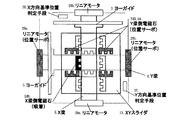
ウエハステージの高速化・高加速度化・高精度化および高真空化が進む中で、X・Y梁とXYスライダの間が、静圧ガイドに代わり電磁ガイドで構成されているステージが提案されている。図1に示すステージは、XYスライダ13とX梁2およびY梁4との間が電磁ガイドで構成されている。図1は分かりやすいように電磁ガイドの構成部材をZ方向にずらして示してある。電磁ガイドとは電磁石の吸引力を利用したアクチュエータを対向して用いて制御することにより、非接触の案内が構成されたものである。X梁2およびY梁4の側面には珪素鋼の薄板を積層して構成したターゲット面17が構成されている。複数の電磁石20も珪素鋼の薄板を積層して構成されている。積層にするのは渦電流の影響を抑えるためである。複数の電磁石20はいずれもE型の形状をしたコアにコイルが巻かれている。このコイルに適宜電流を流すと、Eコアとターゲット面に磁束が通り、電磁石による吸引力が発生する。XYスライダ上板15の側面には反射鏡が構成されており、不図示のレーザ干渉計からX方向1本(Xレーザ光軸)、Y方向2本(Y1レーザ光軸、Y2レーザ光軸Y10)のレーザ光を反射しXYスライダ13のX,Yおよびωz方向位置を計測できる。θz方向はY方向2本の位置計測値の差分とレーザ光の間隔から算出される。図1における複数の電磁石20の配置図を図2に示す。
Along with the progress of high-speed, high-acceleration, high-precision, and high-vacuum wafer stages, a stage has been proposed in which an X / Y beam and an XY slider are composed of electromagnetic guides instead of static pressure guides. Yes. The stage shown in FIG. 1 includes an electromagnetic guide between the
これらの電磁石は吸引力しか働かすことができないため、二つの電磁石をユニットにして対向して用いる。X電磁石X21とX電磁石X22、X電磁石X23とX電磁石X24がこの電磁石ユニットである。X電磁石X21とX電磁石X22の中心を結ぶ線をX12軸X31、X電磁石3とX電磁石4の中心を結ぶ線をX34軸X33と定義する。これらのX12軸X31およびX34軸X33は、それぞれX電磁石X21とX電磁石X22の力線、およびX電磁石X23とX電磁石X24の力線である。同様にしてY方向も、Y電磁石Y21とY電磁石Y22の中心を結ぶ線をY12軸Y31、Y電磁石Y23とY電磁石Y24の中心を結ぶ線をY34軸Y33と定義する。XYスライダ13への一指令とXYスライダ13の計測値とをもとに各電磁石ユニットへの制御指令を生成する制御器を用いることにより、XYスライダ13の位置決めを行うことができる。
Since these electromagnets can work only with an attractive force, two electromagnets are used as a unit and face each other. X electromagnet X21 and X electromagnet X22, X electromagnet X23 and X electromagnet X24 are this electromagnet unit. A line connecting the centers of the X electromagnet X21 and the X electromagnet X22 is defined as an X12 axis X31, and a line connecting the centers of the X electromagnet 3 and the X electromagnet 4 is defined as an X34 axis X33. These X12 axis X31 and X34 axis X33 are the lines of force of X electromagnet X21 and X electromagnet X22, and the lines of force of X electromagnet X23 and X electromagnet X24, respectively. Similarly, in the Y direction, a line connecting the centers of the Y electromagnet Y21 and the Y electromagnet Y22 is defined as a Y12 axis Y31, and a line connecting the Y electromagnet Y23 and the center of the Y electromagnet Y24 is defined as a Y34 axis Y33. By using a controller that generates a control command to each electromagnet unit based on one command to the
このような、電磁ガイド構成のステージにおいても、従来技術と同様な理由から、絶対原点を持っていないインクリメンタル型の位置計測手段を、何らかの基準に対して、原点出しを行うことが必要となる。さらに、初期化駆動によって決められた原点は、全ての位置計測の基準となるため、高精度・高再現性が要求される。 Even in such a stage having an electromagnetic guide structure, for the same reason as in the prior art, it is necessary to perform an origin search for an incremental type position measuring means having no absolute origin with respect to some reference. Furthermore, since the origin determined by the initialization drive is a reference for all position measurements, high accuracy and high reproducibility are required.
しかしながら、従来のX梁・Y梁とXYスライダ間が静圧軸受構成のXY粗動ステージとは異なり、電磁ガイド構成のXY粗動ステージでは、電源投入時にXYスライダにガイド機能はなくステージを初期化駆動することができない。すなわち、XYスライダが電磁ガイドで案内されるステージにおいて、初期化を行う方法が確立されていなかった。したがって、電磁ガイドを初期化するシーケンスが課題であった。 However, unlike the conventional XY coarse movement stage with a static pressure bearing between the X and Y beams and the XY slider, the XY coarse movement stage with an electromagnetic guide structure does not have a guide function for the XY slider when the power is turned on. Cannot be driven. That is, a method for performing initialization on a stage where the XY slider is guided by an electromagnetic guide has not been established. Therefore, the sequence for initializing the electromagnetic guide has been a problem.
本発明は、電源投入時にガイド機能を持たない、電磁ガイドを有する位置決め装置において、高精度・高再現性の初期化シーケンスを実現することを目的とする。 An object of the present invention is to realize an initialization sequence with high accuracy and high reproducibility in a positioning apparatus having an electromagnetic guide that does not have a guide function when power is turned on.
上記目的を達成するために、本発明に係る初期化方法は、互いに直交する第1方向および第2方向に移動可能な対象物と、前記対象物の位置を計測する対象物位置計測手段と、前記対象物を第2方向に案内し、第1方向に移動可能な第1補助構造体と、前記対象物を第1方向に案内し、第2方向に移動可能な第2補助構造体と、前記第1補助構造体および前記第2補助構造体の側面をそれぞれ挟み込むように前記対象物に設けられた少なくとも2対の電磁石ユニットと、少なくとも一方の補助構造体の回転を規制する回転規制手段とを有する位置決め装置の初期化方法であって、前記対象物を前記回転規制手段によって回転を規制された補助構造体に前記電磁石ユニットを用いて吸着する工程と、前記吸着時に前記対象物位置計測手段をオフセットする工程と、を有することを特徴とする。この場合、前記位置決め装置は、前記第1および第2補助構造体の側面に設けられた磁性体部材を有し、前記磁性体部材と前記電磁石ユニットとの間で吸引力を発生することが好ましく、また、前記第1補助構造体の第1方向位置を計測する第1位置計測手段と、前記第2補助構造体の第2方向位置を計測する第2位置計測手段とを有しうる。 In order to achieve the above object, an initialization method according to the present invention includes an object movable in a first direction and a second direction orthogonal to each other, an object position measuring means for measuring the position of the object, A first auxiliary structure that guides the object in the second direction and is movable in the first direction; a second auxiliary structure that guides the object in the first direction and is movable in the second direction; At least two pairs of electromagnet units provided on the object so as to sandwich the side surfaces of the first auxiliary structure and the second auxiliary structure, respectively, and rotation restricting means for restricting rotation of at least one of the auxiliary structures. And a method of adsorbing the object to an auxiliary structure whose rotation is restricted by the rotation restricting means using the electromagnet unit, and the object position measuring means at the time of attracting Off A step of Tsu bets, characterized in that it has a. In this case, it is preferable that the positioning device includes a magnetic member provided on a side surface of the first and second auxiliary structures, and generates an attractive force between the magnetic member and the electromagnet unit. also it can have a first position measuring means for measuring a first direction position of the first auxiliary structure, and a second position measuring means for measuring a second direction position of the second auxiliary structure.
本発明に係る初期化方法は、さらに前記対象物と前記回転規制手段によって回転を規制された補助構造体とを所定の相対位置関係に維持した状態で、他方の補助構造体を前記対象物に吸着する工程、前記対象物と前記回転規制手段によって回転を規制された補助構造体とを所定の相対位置関係に維持した状態で、他方の補助構造体を所定の基準位置まで駆動する工程を有することが好ましい。 Initialization method according to the present invention, a further pre-Symbol object and said is restricted rotated by the rotation restricting means auxiliary structure while maintaining a predetermined relative positional relationship, the object and the other auxiliary structure A step of driving the other auxiliary structure to a predetermined reference position in a state where the object and the auxiliary structure whose rotation is restricted by the rotation restricting means are maintained in a predetermined relative positional relationship. It is preferable to have.
また、本発明は、上記いずれかの位置決め装置を備えることを特徴とする露光装置または上記いずれかの初期化方法を用いたステージによって基板および原版の少なくとも一方を位置決めすることを特徴とする露光装置であってもよく、また、本発明は、上記いずれかの露光装置を用いて基板を露光する工程と、露光された基板を現像する工程とを有することを特徴とするデバイス製造方法にも適用可能である。 According to the present invention, an exposure apparatus comprising any one of the above positioning apparatuses or an exposure apparatus that positions at least one of a substrate and an original by a stage using any one of the above initialization methods. The present invention is also applicable to a device manufacturing method comprising a step of exposing a substrate using any one of the above exposure apparatuses and a step of developing the exposed substrate. Is possible.
電磁ガイド構成の位置決め装置において、高精度・高再現性の初期化シーケンスを実現する。 A highly accurate and reproducible initialization sequence is realized in the electromagnetic guide configuration positioning device.
本発明の好ましい実施の形態については、例えば次のとおりである。
(1)X梁とY梁がクロスバー構成であり、X梁とY梁を取り囲むように構成されたXYスライダが電磁石を搭載した電磁ガイド構成のステージにおいて、X梁およびY梁の少なくとも一方の梁に姿勢を規定するヨーガイドなどを設ける。
A preferred embodiment of the present invention is as follows, for example.
(1) In the stage of the electromagnetic guide configuration in which the X beam and the Y beam have a crossbar configuration and the XY slider configured to surround the X beam and the Y beam mounts an electromagnet, at least one of the X beam and the Y beam A yaw guide that defines the posture of the beam will be provided.
(2)ヨーガイドなど、姿勢の基準のある側の梁、例えばX梁を着地させた状態で、XYスライダの電磁石を用いて、XYスライダを吸着する。そこで、レーザ干渉計などインクリメンタル型の位置計測手段をリセットする。すなわち、姿勢の規定された(θz=0)梁にXYスライダを吸着することで、XYスライダの姿勢を正し(θz=0)、その状態でXYスライダのX梁とのX方向の相対位置および、XYスライダのθz方向回転の絶対位置(θz=0)を明らかにする。 (2) The XY slider is attracted by using an electromagnet of the XY slider in a state where a beam having a reference position such as a yaw guide, for example, an X beam is landed. Therefore, an incremental type position measuring means such as a laser interferometer is reset. That is, by adsorbing the XY slider to a beam with a defined attitude (θz = 0), the attitude of the XY slider is corrected (θz = 0), and in this state, the relative position of the XY slider with the X beam in the X direction The absolute position (θz = 0) of the rotation of the XY slider in the θz direction is clarified.
(3)ここで吸着を解除し、明らかになったX方向の相対位置および、θz方向の絶対位置を元にXYスライダのX梁と対向する、少なくとも2組の電磁石を用いて、X方向およびθz方向の位置サーボをかける。この状態で、XYスライダはY方向に自由に案内される。ここで、XYスライダのY梁と対向する少なくとも1つの電磁石を用い、Y梁に吸着する。XYスライダはθz方向の位置サーボを掛けているので、同時にY梁のθz方向の位置サーボもかかったことになる。この状態で、XYスライダに吸着されたY梁を一体物として、Y梁の両側のリニアモータを用いて基準位置に初期化駆動し、基準位置にてY梁のY方向、θz方向、XYスライダのY方向の位置計測手段を同時にリセットする。 (3) Here, the attraction is released, and at least two sets of electromagnets facing the X beam of the XY slider based on the relative position in the X direction and the absolute position in the θz direction that have been clarified are used. Apply the position servo in the θz direction. In this state, the XY slider is freely guided in the Y direction. Here, at least one electromagnet facing the Y beam of the XY slider is used to attract the Y beam. Since the XY slider is applied with the position servo in the θz direction, the position servo in the θz direction of the Y beam is also applied at the same time. In this state, the Y beam adsorbed by the XY slider is integrated and driven to a reference position by using linear motors on both sides of the Y beam, and the Y direction, θz direction, and XY slider of the Y beam at the reference position are driven. Simultaneously reset the Y-direction position measuring means.
(4)XYスライダのY梁側の吸着を解除し、正しくリセットされたY方向、θz方向、XYスライダのY方向の位置を用いて、Y梁のY方向およびθz方向の位置サーボをかける。次に、同様にXYスライダのX側の少なくとも1つの電磁石を用いてX梁に吸着し、X梁とXYスライダを一体物として、X梁の両端のリニアモータを用いてX方向の基準位置に初期化駆動し、基準位置にてX梁のX方向、XYスライダのX方向の位置計測手段を同時にリセットする。 (4) Release the suction on the Y beam side of the XY slider, and apply the position servo in the Y direction and the θz direction of the Y beam using the correctly reset Y direction, θz direction, and Y position of the XY slider. Next, similarly, at least one electromagnet on the X side of the XY slider is attracted to the X beam, and the X beam and the XY slider are integrated into a reference position in the X direction using linear motors at both ends of the X beam. Initialization driving is performed to simultaneously reset the position measuring means in the X direction of the X beam and the X direction of the XY slider at the reference position.
上記の手順にて、電磁ガイドで案内されたステージの各ユニットの位置計測手段をリセットし、ステージの原点出しを行う。
ヨーガイドがY梁にあっても、Y梁から同様な手順で行うことができるし、両側についていても同様である。また、基準位置を検出する手段は、遮光版およびフォトスイッチでも良いし、機械的スイッチでも良いし、ストッパ位置への突き当てでも良い。以下、本発明の実施例について図面を参照しながら詳細に説明する
According to the above procedure, the position measuring means of each unit of the stage guided by the electromagnetic guide is reset, and the origin of the stage is obtained.
Even if the yaw guide is on the Y beam, the same procedure can be performed from the Y beam, and the same applies to both sides. The means for detecting the reference position may be a light-shielding plate and a photo switch, a mechanical switch, or abutment against the stopper position. Hereinafter, embodiments of the present invention will be described in detail with reference to the drawings.
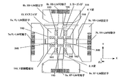
図3は本発明の実施例1に係る位置決め装置を有するステージを上から見た平面図である。このステージは、X梁2およびY梁4がクロスバー構成であり、少なくとも一方の梁として、ヨーガイド3を設けたX梁2と、ヨーガイドのないY梁4と、それらを囲むように構成されたXYスライダ13と、そのX梁2およびY梁4とXYスライダ13の間が電磁ガイドで構成されている。図3は分かりやすいように、XYスライダ13を透過して中の電磁ガイド電磁石と、X梁2およびY梁4を図示している。また、図4〜図8はその動作を示している。
FIG. 3 is a plan view of the stage having the positioning device according to the first embodiment of the present invention as seen from above. In this stage, the
X梁2は、XB−LM可動子6aとXB−LM固定子8aを有するリニアモータ28aおよびXF−LM可動子6bとXF−LM固定子8bを有するリニアモータ28bにより可動である。Y梁4は、YL−LM可動子7aとYL−LM固定子9aを有するリニアモータ29aおよびYR−LM可動子7bとYR−LM固定子9bを有するリニアモータ29bにより可動である。そして、X梁2側にはX梁側電磁石X41〜46が配置され、Y梁4側にはY梁側電磁石Y41〜46が配置されている。
The
さて、従来のX梁・Y梁とXYスライダとの間が静圧軸受構成のXY粗動ステージであったのとは異なり、電磁ガイド構成のXY粗動ステージでは、電源投入時にXYスライダ13にガイド機能がなく、ステージを初期化駆動することができない。そこで本発明では、電磁ガイドの初期化を含めた、ステージの初期化シーケンスを提案する。
Unlike the conventional XY coarse movement stage having a hydrostatic bearing structure between the X beam / Y beam and the XY slider, the XY coarse movement stage having an electromagnetic guide structure has an
(初期化ステップ1)では、図4で示すように、ヨーガイド3のある側のX梁2は、θz方向を拘束されている。そのX梁2を着地させ、XYスライダ13のX梁2側の少なくとも1つの例えば電磁石X45で吸着する。この状態で、XYスライダ13のθz方向の位置計測手段をリセットし、X梁2のX方向およびXYスライダ13のX方向の位置計測手段を仮リセットする。
In (initialization step 1), as shown in FIG. 4, the
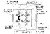
(初期化ステップ2)では、図5で示すように、XYスライダ13のX梁2側の少なくとも2組の例えば電磁石X41,43を用いて、XYスライダ13のθz、X方向の位置サーボをかける。次に、XYスライダ13のY梁4側の少なくとも1つの例えば電磁石Y46を用いて、XYスライダ13をY梁4に吸着する。
In (initialization step 2), as shown in FIG. 5, position servo in the θz and X directions of the
(初期化ステップ3)では、Y方向の位置データの初期化であるが、これは特許文献2で開示された方法を用いることによって、初期化を行うことが可能となる。図6に示すように、この初期化駆動を、Y梁4とXYスライダ13を吸着した状態で同時に行い、基準位置判定手段37まで駆動しY梁4のY方向、θz方向、XYスライダ13のY方向の位置計測手段を同時にリセットする。
(Initialization step 3) is initialization of position data in the Y direction. This can be initialized by using the method disclosed in
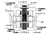
(初期化ステップ4)では、図7に示すように、Y梁4のY方向および、θz方向の位置サーボをかける。X梁2側の少なくとも2組の電磁石によるXYスライダ13のX方向およびθz方向の位置サーボを切り、Y梁4側の少なくとも2組の例えば電磁石Y43,44でXYスライダ13のθz方向の位置サーボをかける。着地していたX梁2を浮上させ、X梁2側の少なくとも1つの例えば電磁石X45を用いて、XYスライダ13をX梁2に吸着する。
In (initialization step 4), as shown in FIG. 7, position servo of the Y beam 4 in the Y direction and the θz direction is applied. The position servo in the X direction and the θz direction of the
(初期化ステップ5)では、(初期化ステップ3)と同様に、特許文献2で開示された方法を用いることによって、X方向の位置データの初期化を行う。図8に示すように、この初期化駆動を、X梁2とXYスライダ13を吸着した状態で同時に行い、基準位置判定手段まで駆動し、X梁2のX方向、XYスライダ13のX方向の位置計測手段を同時にリセットする。
In (initialization step 5), as in (initialization step 3), the position data in the X direction is initialized by using the method disclosed in
この手順で、X梁2のX方向、(θz方向はヨーガイド3で拘束)、Y梁4のY方向・θz方向、XYスライダ13のX方向・Y方向・θz方向の全ての軸における位置計測手段の初期化を完了する。なお、梁2,4および、XYスライダ13が基準位置判定手段36,37に到達したか否かを判定するための方法は、
・ 梁に遮光板を設け、基準位置にフォトインタラプタを設ける方法
・ 基準位置にレバースイッチなどの機械的スイッチを設ける方法
・ 基準位置に突き当てストッパを設ける方法
などの方法をとることが望ましい。また、ヨーガイドをY梁4側だけに設ける場合も同様である。
With this procedure, the
-A method of providing a light shielding plate on the beam and a photo interrupter at the reference position-A method of providing a mechanical switch such as a lever switch at the reference position-A method of providing a butting stopper at the reference position is desirable. The same applies when the yaw guide is provided only on the Y beam 4 side.
なお、(初期化ステップ1)において、X梁2に吸着後、XYスライダ13のY梁4側の電磁石を用いてY梁4にも同時に吸着し、正しく姿勢の出たX梁2に吸着したXYスライダ13にY梁4を吸着させることにより正しい姿勢の出たY梁4を着地させ、初期化ステップ4および5で先にX方向の初期化を行ってから初期化ステップ2および3を行ってY方向の初期化を行っても良い。
In (Initialization Step 1), after being attracted to the
その場合、初期化ステップ4ではY梁4の位置サーボをかける代わりに、着地させて行う。そして、初期化ステップ2でX梁2を着地させる代わりにX方向に位置サーボをかけ、初期化ステップ3を行う。
In that case, the initialization step 4 is performed by landing instead of applying the position servo of the Y beam 4. Then, instead of landing the
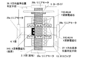
図9は本発明の実施例2に係る位置決め装置を有するステージを上から見た平面図である。このステージは、X梁2およびY梁4がクロスバー構成であり、X梁2およびY梁4の両方に案内手段として対応するヨーガイド3,5を設け、それらを囲むように構成されたXYスライダ13と、そのX梁2およびY梁4とXYスライダ13との間が電磁ガイドで構成されている。図9は分かりやすいように、XYスライダ13を透過して中の電磁ガイドと、X梁2おおびY梁4を図示している。図10〜図14はその動作を示している。
FIG. 9 is a plan view of a stage having a positioning device according to
X梁2は、XB−LM可動子6aとXB−LM固定子8aを有するリニアモータ28aおよびXF−LM可動子6bとXF−LM固定子8bを有するリニアモータ28bにより可動である。Y梁4は、YL−LM可動子7aとYL−LM固定子9aを有するリニアモータ29aおよびYR−LM可動子7bとYR−LM固定子9bを有するリニアモータ29bにより可動である。そして、XYスライダにおいて、X梁2側にはX梁側電磁石X41〜46が配置され、Y梁4側にはY梁側電磁石Y41〜46が配置されている。
The
実施例1で説明した通り、従来のX梁・Y梁とXYスライダ間が静圧軸受構成のXY粗動ステージとは異なり、電磁ガイド構成のXY粗動ステージでは、電源投入時にXYスライダにガイド機能はなくステージを初期化駆動することができない。そこで本発明では、電磁ガイドの初期化を含めた、ステージの初期化シーケンスを提案する。 As described in the first embodiment, unlike the XY coarse movement stage having a static pressure bearing structure between the conventional X beam / Y beam and the XY slider, the XY coarse movement stage having an electromagnetic guide structure guides the XY slider when the power is turned on. There is no function and the stage cannot be initialized. Therefore, the present invention proposes a stage initialization sequence including initialization of the electromagnetic guide.
(初期化ステップ1)では、図10に示すように、X梁2およびY梁4の両方ともヨーガイド3,5によりθz方向を拘束(回転を規制)されている。X梁2およびY梁4の両方ともに、少なくとも1つずつの例えば電磁石X45,Y46を用いXYスライダ13に吸着する。この状態で、XYスライダ13のθz方向の位置計測手段をリセットし、X梁2のX方向、Y梁4のY方向、XYスライダ13のX方向・Y方向の位置計測手段を仮リセットする。
In (initialization step 1), as shown in FIG. 10, both the
(初期化ステップ2)では、図11で示すように、X梁2を着地させ、XYスライダ13のX梁2側の少なくとも2組の電磁石を用いて、XYスライダ13のθz、X方向の位置サーボをかける。次に、XYスライダ13のY梁4側の少なくとも1つの例えば電磁石Y46を用いて、XYスライダ13をY梁4に吸着する。
In (initialization step 2), as shown in FIG. 11, the
(初期化ステップ3)では、Y方向の位置データの初期化であるが、これは特許文献2で開示された方法を用いることによって、初期化を行うことが可能となる。図12に示すように、この初期化駆動を、Y梁4とXYスライダ13を吸着した状態で同時に行い、基準位置判定手段37まで駆動しY梁4のY方向、XYスライダ13のY方向の位置計測手段を同時にリセットする。
(Initialization step 3) is initialization of position data in the Y direction. This can be initialized by using the method disclosed in
(初期化ステップ4)では、図13で示すように、Y梁4のY方向の位置サーボをかける。X梁2側の少なくとも2組の電磁石によるXYスライダ13X方向およびθz方向の位置サーボを切り、Y梁4側の少なくとも2組の電磁石でXYスライダ13のθz方向の位置サーボをかける。着地していたX梁2を浮上させ、X梁2側の少なくとも1つの例えば電磁石X45を用いて、XYスライダ13をX梁2に吸着する。
In (initialization step 4), as shown in FIG. 13, the position servo in the Y direction of the Y beam 4 is applied. The position servo in the XY slider 13X direction and the θz direction is cut by at least two sets of electromagnets on the
(初期化ステップ5)では、(初期化ステップ3)と同様に、特許文献2で開示された方法を用いることによって、X方向の位置データの初期化を行う。図14に示すように、この初期化駆動を、X梁2とXYスライダ13を吸着した状態で同時に行い、基準位置判定手段36まで駆動し、X梁2のX方向、XYスライダ13のX方向の位置計測手段を同時にリセットする。
In (initialization step 5), as in (initialization step 3), the position data in the X direction is initialized by using the method disclosed in
この手順で、X梁2のX方向(θz方向はヨーガイド3で拘束)、Y梁4のY方向(θz方向はヨーガイド5で拘束)、XYスライダ13のX方向・Y方向・θz方向の全ての軸における位置計測手段の初期化を完了する。なお、梁2,4および、XYスライダ13が基準位置に到達したか否かを判定するための方法は、
・ 梁に遮光板を設け、基準位置にフォトインタラプタを設ける方法
・ 基準位置にレバースイッチなどの機械的スイッチを設ける方法
・ 基準位置に突き当てストッパを設ける方法
などのいずれかの方法をとることが望ましい。
In this procedure, the X direction of the X beam 2 (the θz direction is constrained by the yaw guide 3), the Y direction of the Y beam 4 (the θz direction is constrained by the yaw guide 5), and the X direction, Y direction, and θz direction of the
-A method of providing a light shielding plate on the beam and a photo interrupter at the reference position-A method of providing a mechanical switch such as a lever switch at the reference position-A method of providing an abutment stopper at the reference position desirable.
また、初期化ステップ2および3は初期化ステップ4および5で先にX方向の初期化を行ってから行っても良い。その場合、初期化ステップ4ではY梁4を位置サーボをかける代わりに、着地させて先に行う。そして、初期化ステップ2でX梁2を着地させる代わりにX方向に位置サーボをかけ、初期化ステップ3を行う。
Further, the initialization steps 2 and 3 may be performed after the initialization steps 4 and 5 have been initialized in the X direction first. In this case, in the initialization step 4, the Y beam 4 is landed first instead of being subjected to position servo. Then, instead of landing the
吸着を行う電磁石は実施例の図で示した電磁石に限らないし、複数個を用いて吸着しても良いし、全てを用いても良い。位置サーボを行う電磁石は実施例の図で示した2組に限らず、どの組み合わせで行っても良いし、全てを使ってもよい。 The electromagnets to be attracted are not limited to the electromagnets shown in the drawings of the embodiments, and a plurality of electromagnets may be attracted or all may be used. The electromagnets that perform the position servo are not limited to the two sets shown in the drawings of the embodiments, and any combination or all of them may be used.
なお、XYスライダ13の電磁ガイドで吸着を行う際、図15に示すように、XYスライダ13の例えば電磁石43,44,46の面とY梁4のターゲット面17を密着するように吸着してもいいし、図16に示すように、少なくとも2個のストッパ48,49によって接触して吸着しても良い。ストッパ48,49は吸着に使用する電磁石より外側に配置するのが望ましい。
Note that, when attracting with the electromagnetic guide of the
図19は、上記の位置決め装置を有するステージをウエハステージとする半導体デバイス製造用の露光装置を示す。
この露光装置は、半導体集積回路等の半導体デバイスや、マイクロマシン、薄膜磁気ヘッド等の微細なパターンが形成されたデバイスの製造に利用され、原版であるレチクルRを介して基板としての半導体ウエハW上に光源61からの露光エネルギーとしての露光光(この用語は、可視光、紫外光、EUV光、X線、電子線、荷電粒子線等の総称である)を投影系としての投影レンズ(この用語は、屈折レンズ、反射レンズ、反射屈折レンズシステム、荷電粒子レンズ等の総称である)62を介して照射することによって、基板上に所望のパターンを形成している。
FIG. 19 shows an exposure apparatus for manufacturing a semiconductor device in which a stage having the above positioning apparatus is a wafer stage.
This exposure apparatus is used for manufacturing a semiconductor device such as a semiconductor integrated circuit or a device on which a fine pattern is formed, such as a micromachine or a thin film magnetic head, on a semiconductor wafer W as a substrate via a reticle R which is an original plate. Projection lens (this term is a generic term for visible light, ultraviolet light, EUV light, X-rays, electron beams, charged particle beams, etc.) as a projection system (this term) Irradiates through a refraction lens, a reflection lens, a catadioptric lens system, a charged particle lens, and the like (62) to form a desired pattern on the substrate.
この露光装置は、定盤51上にガイド52とリニアモータ固定子72を固設している。リニアモータ固定子72は多相電磁コイルを、リニアモータ可動子71は永久磁石群を有している。リニアモータ可動子71を可動部53として、ステージである可動ガイド54に接続し、リニアモータM1の駆動によって可動ガイド54を紙面法線方向に移動させる。可動部53は、定盤51の上面を基準に静圧軸受55で、ガイド52の側面を基準に静圧軸受56で支持される。
In this exposure apparatus, a
可動ガイド54を跨ぐようにして配置したステージである移動ステージ57は静圧軸受58によって支持されている。この移動ステージ57は、上記と同様のリニアモータM2によって駆動され、可動ガイド54を基準に移動ステージ57が紙面左右方向に移動する。移動ステージ57の動きは、移動ステージ57に固設したミラー59および干渉計60を用いて計測する。
A moving
移動ステージ57に搭載したチャック上に基板であるウエハWを保持し、光源61、投影光学系62によって、原版であるレチクルRのパターンをウエハW上の各領域にステップアンドリピートもしくはステップアンドスキャンで縮小転写する。
A wafer W, which is a substrate, is held on a chuck mounted on a moving
なお、本発明の位置決め装置は、マスクを使用せずに半導体ウエハ上に回路パターンを直接描画してレジストを露光するタイプの露光装置にも、同様に適用できる。 Note that the positioning apparatus of the present invention can be similarly applied to an exposure apparatus that directly draws a circuit pattern on a semiconductor wafer without using a mask and exposes a resist.
次に、この露光装置を利用した半導体デバイスの製造プロセスを説明する。図20は半導体デバイスの全体的な製造プロセスのフローを示す図である。ステップ1(回路設計)では半導体デバイスの回路設計を行う。ステップ2(マスク作製)では設計した回路パターンに基づいてマスクを作製する。 Next, a semiconductor device manufacturing process using this exposure apparatus will be described. FIG. 20 is a diagram showing a flow of an entire manufacturing process of a semiconductor device. In step 1 (circuit design), a semiconductor device circuit is designed. In step 2 (mask fabrication), a mask is fabricated based on the designed circuit pattern.
一方、ステップ3(ウエハ製造)ではシリコン等の材料を用いてウエハを製造する。ステップ4(ウエハプロセス)は前工程と呼ばれ、上記のマスクとウエハを用いて、上記の露光装置によりリソグラフィ技術を利用してウエハ上に実際の回路を形成する。次のステップ5(組み立て)は後工程と呼ばれ、ステップ5によって作製されたウエハを用いて半導体チップ化する工程であり、アッセンブリ工程(ダイシング、ボンディング)、パッケージング工程(チップ封入)等の組み立て工程を含む。ステップ6(検査)ではステップ5で作製された半導体デバイスの動作確認テスト、耐久性テスト等の検査を行う。こうした工程を経て半導体デバイスが完成し、ステップ7でこれを出荷する。
On the other hand, in step 3 (wafer manufacture), a wafer is manufactured using a material such as silicon. Step 4 (wafer process) is called a pre-process, and an actual circuit is formed on the wafer by using the above-described exposure apparatus and lithography technology using the above-described mask and wafer. The next step 5 (assembly) is called a post-process, which is a process for forming a semiconductor chip using the wafer produced in
上記ステップ4のウエハプロセスは以下のステップを有する。ウエハの表面を酸化させる酸化ステップ、ウエハ表面に絶縁膜を成膜するCVDステップ、ウエハ上に電極を蒸着によって形成する電極形成ステップ、ウエハにイオンを打ち込むイオン打ち込みステップ、ウエハに感光剤を塗布するレジスト処理ステップ、上記の露光装置によって回路パターンをレジスト処理ステップ後のウエハに転写する露光ステップ、露光ステップで露光したウエハを現像する現像ステップ、現像ステップで現像したレジスト像以外の部分を削り取るエッチングステップ、エッチングが済んで不要となったレジストを取り除くレジスト剥離ステップ。これらのステップを繰り返し行うことによって、ウエハ上に多重に回路パターンを形成する。 The wafer process in step 4 includes the following steps. An oxidation step for oxidizing the surface of the wafer, a CVD step for forming an insulating film on the wafer surface, an electrode formation step for forming electrodes on the wafer by vapor deposition, an ion implantation step for implanting ions on the wafer, and applying a photosensitive agent to the wafer A resist processing step, an exposure step for transferring the circuit pattern to the wafer after the resist processing step by the above exposure apparatus, a development step for developing the wafer exposed in the exposure step, and an etching step for scraping off portions other than the resist image developed in the development step A resist stripping step that removes the resist that has become unnecessary after etching. By repeating these steps, multiple circuit patterns are formed on the wafer.
1:ステージ定盤、2:粗動X梁、3:Xヨーガイド、4:粗動Y梁、5:Yヨーガイド、6a,6b:Xリニアモータ可動子、7a,7b:Yリニアモータ可動子、8a,8b:Xリニアモータ固定子、9a,9b:Yリニアモータ固定子、X10〜12:Xレーザ光軸、Y10〜12:Yレーザ光軸、13:XYスライダ、14:XYスライダ底板、15:XYスライダ上板、16:微動ステージ、17:ターゲット面、18:静圧軸受、20:電磁石、X21〜24:X電磁石、Y21〜24:Y電磁石、X25,26:X加速電磁石、Y25,26:Y加速電磁石、28a,28b,29a,29b:リニアモータ、X31:X12軸、Y31:Y12軸、X33:X34軸、Y33:Y34軸、36:X方向基準位置判定手段、37:Y方向基準位置判定手段、X41〜46:X梁側電磁石、Y41〜46:Y梁側電磁石、51:定盤、52:ガイド、53:可動部、54:可動ガイド、55,56:静圧軸受、57:移動ステージ、58:静圧軸受、59:ミラー、60:干渉計、61:光源、62:投影光学系、71:リニアモータ可動子、72:リニアモータ固定子、M1,M2:リニアモータ。 1: stage surface plate, 2: coarse X beam, 3: X yaw guide, 4: coarse Y beam, 5: Y yaw guide, 6a, 6b: X linear motor mover, 7a, 7b: Y linear motor mover, 8a, 8b: X linear motor stator, 9a, 9b: Y linear motor stator, X10-12: X laser optical axis, Y10-12: Y laser optical axis, 13: XY slider, 14: XY slider bottom plate, 15 : XY slider upper plate, 16: fine movement stage, 17: target surface, 18: static pressure bearing, 20: electromagnet, X21-24: X electromagnet, Y21-24: Y electromagnet, X25, 26: X acceleration electromagnet, Y25, 26: Y accelerating electromagnet, 28a, 28b, 29a, 29b: linear motor, X31: X12 axis, Y31: Y12 axis, X33: X34 axis, Y33: Y34 axis, 36: X direction reference position determining means, 3, : Y direction reference position determination means, X41 to 46: X beam side electromagnet, Y41 to 46: Y beam side electromagnet, 51: Surface plate, 52: Guide, 53: Movable part, 54: Movable guide, 55, 56: Static Pressure bearing, 57: Moving stage, 58: Hydrostatic bearing, 59: Mirror, 60: Interferometer, 61: Light source, 62: Projection optical system, 71: Linear motor movable element, 72: Linear motor stator, M1, M2 : Linear motor.
Claims (10)
前記対象物の位置を計測する対象物位置計測手段と、
前記対象物を第2方向に案内し、第1方向に移動可能な第1補助構造体と、
前記対象物を第1方向に案内し、第2方向に移動可能な第2補助構造体と、
前記第1補助構造体および前記第2補助構造体の側面をそれぞれ挟み込むように前記対象物に設けられた少なくとも2対の電磁石ユニットと、
少なくとも一方の補助構造体の回転を規制する回転規制手段とを有する位置決め装置の初期化方法であって、
前記対象物を前記回転規制手段によって回転を規制された補助構造体に前記電磁石ユニットを用いて吸着する工程と、
前記吸着時に前記対象物位置計測手段をオフセットする工程と、
を有することを特徴とする初期化方法。 An object movable in a first direction and a second direction orthogonal to each other ;
Object position measuring means for measuring the position of the object;
A first auxiliary structure that guides the object in a second direction and is movable in the first direction;
A second auxiliary structure that guides the object in a first direction and is movable in a second direction;
At least two pairs of electromagnet units provided on the object so as to sandwich the side surfaces of the first auxiliary structure and the second auxiliary structure, respectively,
A method of initializing a position-decided Me device having a rotation restricting means for restricting the rotation of at least one auxiliary structure,
Using the electromagnet unit to attract the object to the auxiliary structure whose rotation is restricted by the rotation restricting means;
Offsetting the object position measuring means during the suction;
An initialization method characterized by comprising:
前記第1補助構造体の第1方向位置を計測する第1位置計測手段と、
前記第2補助構造体の第2方向位置を計測する第2位置計測手段と、
を有することを特徴とする請求項1〜3のいずれかに記載の初期化方法。 The positioning device comprises:
First position measuring means for measuring a first direction position of the first auxiliary structure;
Second position measuring means for measuring a second direction position of the second auxiliary structure;
The initialization method according to claim 1 , comprising:
基準位置としての第1基準位置検出手段および第2基準位置検出手段を有することを特徴とする請求項4に記載の初期化方法。 The first position measuring means and the second position measuring means measure their relative positions;
5. The initialization method according to claim 4 , further comprising first reference position detection means and second reference position detection means as reference positions.
露光された基板を現像する工程とを有することを特徴とするデバイス製造方法。 Exposing the substrate using the exposure apparatus according to claim 9 ;
And a step of developing the exposed substrate .
Priority Applications (3)
| Application Number | Priority Date | Filing Date | Title |
|---|---|---|---|
| JP2004089502A JP4447949B2 (en) | 2004-03-25 | 2004-03-25 | Method for initializing positioning apparatus, exposure apparatus and device manufacturing method |
| US11/084,115 US7157722B2 (en) | 2004-03-25 | 2005-03-21 | Positioning device and method of initializing a positioning device |
| US11/557,137 US7375346B2 (en) | 2004-03-25 | 2006-11-07 | Positioning device and method of initializing a positioning device |
Applications Claiming Priority (1)
| Application Number | Priority Date | Filing Date | Title |
|---|---|---|---|
| JP2004089502A JP4447949B2 (en) | 2004-03-25 | 2004-03-25 | Method for initializing positioning apparatus, exposure apparatus and device manufacturing method |
Publications (3)
| Publication Number | Publication Date |
|---|---|
| JP2005278325A JP2005278325A (en) | 2005-10-06 |
| JP2005278325A5 JP2005278325A5 (en) | 2008-02-21 |
| JP4447949B2 true JP4447949B2 (en) | 2010-04-07 |
Family
ID=34988682
Family Applications (1)
| Application Number | Title | Priority Date | Filing Date |
|---|---|---|---|
| JP2004089502A Expired - Fee Related JP4447949B2 (en) | 2004-03-25 | 2004-03-25 | Method for initializing positioning apparatus, exposure apparatus and device manufacturing method |
Country Status (2)
| Country | Link |
|---|---|
| US (2) | US7157722B2 (en) |
| JP (1) | JP4447949B2 (en) |
Families Citing this family (11)
| Publication number | Priority date | Publication date | Assignee | Title |
|---|---|---|---|---|
| US7428850B2 (en) * | 2005-02-24 | 2008-09-30 | Applied Materials, Israel,Ltd. | Integrated in situ scanning electronic microscope review station in semiconductor wafers and photomasks optical inspection system |
| US7566997B2 (en) * | 2007-03-30 | 2009-07-28 | Baldor Electric Company | Gas bearing system |
| CN102059576B (en) * | 2010-11-25 | 2012-02-08 | 西安理工大学 | Biaxial linear moving micro driving device |
| US8418350B2 (en) | 2011-07-11 | 2013-04-16 | Baldor Electric Company | Method of forming a secondary for linear drive motor comprising sheet of highly permeable magnetic material having synchronized motor teeth, encoder teeth, and commutation tracks integrally formed therein |
| US8803371B2 (en) | 2011-07-11 | 2014-08-12 | Baldor Electric Company | Secondary for linear drive motor comprising sheet of highly permeable magnetic material having synchronized motor teeth, encoder teeth, and commutation tracks integrally formed therein |
| US8791608B2 (en) | 2011-07-11 | 2014-07-29 | Baldor Electric Company | Primary for linear drive motor with solid steel stacks |
| US8922068B2 (en) | 2011-07-11 | 2014-12-30 | Baldor Electric Company | Linear drive motor with improved bearing system |
| JP2013211507A (en) * | 2011-08-08 | 2013-10-10 | Rohm Co Ltd | Photointerrupter, manufacturing method of photointerrupter, and mounting structure of photointerrupter |
| CN102837225B (en) * | 2012-10-12 | 2014-11-19 | 飞迅科技(苏州)有限公司 | Combination-type calibration positioning mechanism |
| CN107664920B (en) * | 2016-07-29 | 2019-04-12 | 上海微电子装备(集团)股份有限公司 | Electromagnetism track-type facilities |
| CN117072561B (en) * | 2023-10-18 | 2023-12-19 | 无锡星微科技有限公司 | Combinable multi-shaft structure and linear motion platform with same |
Family Cites Families (6)
| Publication number | Priority date | Publication date | Assignee | Title |
|---|---|---|---|---|
| JPH0564487A (en) | 1991-09-04 | 1993-03-12 | Canon Inc | Positioning table unit |
| JPH11316607A (en) | 1998-04-30 | 1999-11-16 | Canon Inc | Stage device, exposure device and device production method |
| DE50114723D1 (en) * | 2000-09-15 | 2009-04-09 | Vistec Electron Beam Gmbh | Six-axis positioning system with magnetic-field-free space |
| US6788385B2 (en) * | 2001-06-21 | 2004-09-07 | Nikon Corporation | Stage device, exposure apparatus and method |
| JP3762401B2 (en) | 2002-09-30 | 2006-04-05 | キヤノン株式会社 | Positioning apparatus, exposure apparatus, and device manufacturing method |
| JP2005005393A (en) * | 2003-06-10 | 2005-01-06 | Canon Inc | Stage equipment, optical lithography system, and method for manufacturing device |
-
2004
- 2004-03-25 JP JP2004089502A patent/JP4447949B2/en not_active Expired - Fee Related
-
2005
- 2005-03-21 US US11/084,115 patent/US7157722B2/en not_active Expired - Fee Related
-
2006
- 2006-11-07 US US11/557,137 patent/US7375346B2/en not_active Expired - Fee Related
Also Published As
| Publication number | Publication date |
|---|---|
| US20070063149A1 (en) | 2007-03-22 |
| US20050211920A1 (en) | 2005-09-29 |
| US7157722B2 (en) | 2007-01-02 |
| US7375346B2 (en) | 2008-05-20 |
| JP2005278325A (en) | 2005-10-06 |
Similar Documents
| Publication | Publication Date | Title |
|---|---|---|
| JP4268333B2 (en) | Balanced positioning system for use in a lithographic projection apparatus | |
| US7375346B2 (en) | Positioning device and method of initializing a positioning device | |
| US7280185B2 (en) | Stage system including fine-motion cable unit, exposure apparatus, and method of manufacturing device | |
| JP4639517B2 (en) | Stage apparatus, lithography system, positioning method, and stage apparatus driving method | |
| US7282874B2 (en) | Alignment apparatus, exposure apparatus, and device manufacturing method | |
| KR101729791B1 (en) | Exposure apparatus, exposure method, and device manufacturing method | |
| US7348695B2 (en) | Linear motor, moving stage system, exposure apparatus, and device manufacturing method | |
| JPH11189332A (en) | Stage device, exposure device using it, and manufacture of device | |
| US20060044537A1 (en) | Stage alignment apparatus and its control method, exposure apparatus, and semiconductor device manufacturing method | |
| US6777896B2 (en) | Methods and apparatus for initializing a planar motor | |
| KR100715785B1 (en) | Positioning device, exposure apparatus, and device manufacturing method | |
| JP4298547B2 (en) | Positioning apparatus and exposure apparatus using the same | |
| US20030173833A1 (en) | Wafer stage with magnetic bearings | |
| US6686991B1 (en) | Wafer stage assembly, servo control system, and method for operating the same | |
| JP2004228473A (en) | Movable stage device | |
| TWI754681B (en) | Motor assembly, lithographic apparatus and device manufacturing method | |
| US7385318B2 (en) | Positioning system, magnetic bearing, and method of controlling the same | |
| JP4262153B2 (en) | Positioning apparatus and exposure apparatus using the same | |
| WO2014136143A1 (en) | Mobile device, exposure device, and device production method | |
| US6980279B2 (en) | Interferometer system for measuring a height of wafer stage | |
| WO2001081171A1 (en) | Wafer stage with magnetic bearings | |
| JP2004342825A (en) | Magnetic guide apparatus | |
| JP2004241576A (en) | Positioning device | |
| JP2006156554A (en) | Stage device and aligner using the same, and device manufacturing method | |
| WO2016041731A1 (en) | Object table, lithographic apparatus and device manufacturing method |
Legal Events
| Date | Code | Title | Description |
|---|---|---|---|
| A621 | Written request for application examination |
Free format text: JAPANESE INTERMEDIATE CODE: A621 Effective date: 20070323 |
|
| A521 | Request for written amendment filed |
Free format text: JAPANESE INTERMEDIATE CODE: A523 Effective date: 20080107 |
|
| RD01 | Notification of change of attorney |
Free format text: JAPANESE INTERMEDIATE CODE: A7421 Effective date: 20090406 |
|
| TRDD | Decision of grant or rejection written | ||
| A01 | Written decision to grant a patent or to grant a registration (utility model) |
Free format text: JAPANESE INTERMEDIATE CODE: A01 Effective date: 20100119 |
|
| A01 | Written decision to grant a patent or to grant a registration (utility model) |
Free format text: JAPANESE INTERMEDIATE CODE: A01 |
|
| A977 | Report on retrieval |
Free format text: JAPANESE INTERMEDIATE CODE: A971007 Effective date: 20100121 |
|
| A61 | First payment of annual fees (during grant procedure) |
Free format text: JAPANESE INTERMEDIATE CODE: A61 Effective date: 20100121 |
|
| FPAY | Renewal fee payment (event date is renewal date of database) |
Free format text: PAYMENT UNTIL: 20130129 Year of fee payment: 3 |
|
| R150 | Certificate of patent or registration of utility model |
Free format text: JAPANESE INTERMEDIATE CODE: R150 |
|
| FPAY | Renewal fee payment (event date is renewal date of database) |
Free format text: PAYMENT UNTIL: 20140129 Year of fee payment: 4 |
|
| LAPS | Cancellation because of no payment of annual fees |