JP4447792B2 - A device for folding containers such as CD discs, etc. - Google Patents
A device for folding containers such as CD discs, etc. Download PDFInfo
- Publication number
- JP4447792B2 JP4447792B2 JP2000603951A JP2000603951A JP4447792B2 JP 4447792 B2 JP4447792 B2 JP 4447792B2 JP 2000603951 A JP2000603951 A JP 2000603951A JP 2000603951 A JP2000603951 A JP 2000603951A JP 4447792 B2 JP4447792 B2 JP 4447792B2
- Authority
- JP
- Japan
- Prior art keywords
- jig
- casing
- folding
- slide part
- finished
- Prior art date
- Legal status (The legal status is an assumption and is not a legal conclusion. Google has not performed a legal analysis and makes no representation as to the accuracy of the status listed.)
- Expired - Fee Related
Links
- 238000004806 packaging method and process Methods 0.000 claims description 9
- 238000003780 insertion Methods 0.000 claims description 4
- 230000037431 insertion Effects 0.000 claims description 4
- 230000000295 complement effect Effects 0.000 claims description 2
- 239000000463 material Substances 0.000 claims description 2
- 238000004519 manufacturing process Methods 0.000 abstract description 14
- 239000003292 glue Substances 0.000 abstract 2
- 238000000034 method Methods 0.000 description 8
- 239000000853 adhesive Substances 0.000 description 6
- 230000001070 adhesive effect Effects 0.000 description 6
- 210000000078 claw Anatomy 0.000 description 6
- 238000000926 separation method Methods 0.000 description 5
- 239000005022 packaging material Substances 0.000 description 4
- 238000009434 installation Methods 0.000 description 2
- 238000005192 partition Methods 0.000 description 2
- 230000015572 biosynthetic process Effects 0.000 description 1
- 230000000994 depressogenic effect Effects 0.000 description 1
- 238000010586 diagram Methods 0.000 description 1
- 238000005516 engineering process Methods 0.000 description 1
- 238000001125 extrusion Methods 0.000 description 1
- 230000006870 function Effects 0.000 description 1
- 238000007726 management method Methods 0.000 description 1
- 239000000155 melt Substances 0.000 description 1
- 230000003287 optical effect Effects 0.000 description 1
- 230000002093 peripheral effect Effects 0.000 description 1
- 238000002360 preparation method Methods 0.000 description 1
- 238000003825 pressing Methods 0.000 description 1
- 238000004080 punching Methods 0.000 description 1
- 238000009958 sewing Methods 0.000 description 1
- 239000007787 solid Substances 0.000 description 1
Images


Classifications
-
- B—PERFORMING OPERATIONS; TRANSPORTING
- B65—CONVEYING; PACKING; STORING; HANDLING THIN OR FILAMENTARY MATERIAL
- B65B—MACHINES, APPARATUS OR DEVICES FOR, OR METHODS OF, PACKAGING ARTICLES OR MATERIALS; UNPACKING
- B65B25/00—Packaging other articles presenting special problems
- B65B25/002—Packaging other articles presenting special problems packaging of information carriers, e.g. records, CD, DVD
-
- B—PERFORMING OPERATIONS; TRANSPORTING
- B31—MAKING ARTICLES OF PAPER, CARDBOARD OR MATERIAL WORKED IN A MANNER ANALOGOUS TO PAPER; WORKING PAPER, CARDBOARD OR MATERIAL WORKED IN A MANNER ANALOGOUS TO PAPER
- B31B—MAKING CONTAINERS OF PAPER, CARDBOARD OR MATERIAL WORKED IN A MANNER ANALOGOUS TO PAPER
- B31B2105/00—Rigid or semi-rigid containers made by assembling separate sheets, blanks or webs
-
- B—PERFORMING OPERATIONS; TRANSPORTING
- B31—MAKING ARTICLES OF PAPER, CARDBOARD OR MATERIAL WORKED IN A MANNER ANALOGOUS TO PAPER; WORKING PAPER, CARDBOARD OR MATERIAL WORKED IN A MANNER ANALOGOUS TO PAPER
- B31B—MAKING CONTAINERS OF PAPER, CARDBOARD OR MATERIAL WORKED IN A MANNER ANALOGOUS TO PAPER
- B31B2120/00—Construction of rigid or semi-rigid containers
- B31B2120/60—Construction of rigid or semi-rigid containers of drawer-and-shell type
-
- B—PERFORMING OPERATIONS; TRANSPORTING
- B31—MAKING ARTICLES OF PAPER, CARDBOARD OR MATERIAL WORKED IN A MANNER ANALOGOUS TO PAPER; WORKING PAPER, CARDBOARD OR MATERIAL WORKED IN A MANNER ANALOGOUS TO PAPER
- B31B—MAKING CONTAINERS OF PAPER, CARDBOARD OR MATERIAL WORKED IN A MANNER ANALOGOUS TO PAPER
- B31B50/00—Making rigid or semi-rigid containers, e.g. boxes or cartons
- B31B50/26—Folding sheets, blanks or webs
Abstract
Description
【0001】
(技術分野)
本発明は、請求項の前文に示される様に、厚紙又は類似品の製造工程にある素材に先行し押し抜き、折りたたみノッチを提供し、包装材を折りたたみ、それに円盤型の製品、特にコンパクトディスク又は類似品を収容する装置に関するものである。
【0002】
(背景技術)
このタイプの装置は、スウェーデン特許発明明細書SE-C-508483より知られており、また包装材を起立させ、それに円盤形の製品、特にコンパクトディスクを入れるのに適しているが、前記包装材は公告発明WO/97/38919号に、そして特殊な形状としてスウェーデン特許出願番号9900018-1号に記載されている包装材の種類である。厚紙より作製されたこれら包装材には、現在より一般的であるプラスチック製包装材に比べ多くの利点がある。既知装置では、直線的にステーションを通過するか、又は多くの異なる作業を実行する様に配置された二本のエンドレス型、段階式、又は連続送り出し式エンドレスコンベヤが巡らされており、そしてこれらコンベヤは相互に直角に向かい合っており、一方のコンベヤからのケーシング部品と、もう一方のコンベヤからのスライド部品を組み立てる。この様な理由から、装置全体は比較的大型になる。その結果、とりわけ装置は分解せずに輸送することができず、分解と組み立ての両方の作業が必要となり、時間を浪費することになる。
【0003】
本発明の目的は、単一ベッドへの取り付けに十分な程小型であり、ユニットとして工場に設置し運搬することができ、例えばおそらくは電源コントロール用のキャビネットまたは同等品を除いて、標準型のフォークリフトによって全体を動かすことができる様な、上記の目的に適した装置を提供することである。従って原則的には、装置は世界中のいかなる場所にも航空機を利用し、直ぐに工場調製済みの状態で出荷することができる。別の目的は、迅速かつ信頼性の高い固定式の包装装置を提供することである。第三の目的は、拡張性を最大にするために、機械式制御や軸、歯車、カム輪等の手段による共同作業に替わり、完全にコンピューターで制御されたメカニズムを有する固定式の包装装置を提供することである。
【0004】
(発明の開示)
これらの、及びその他の有利な目的は、請求項1の特徴部分に記載されている様に構成された形式の装置により始めて達成される。従って第一及び第二トラックは原則的には、円形コンベヤ形式に取り付けられたジグの形状に配置され、その結果各トラックはその上に複数のジグが取り付けられている回転軸を含んでおり、そして前記ジグにはそれぞれケーシング部品とスライド部品を保持し、段階的に完成させるための保持装置が提供されており、回転テーブルの軸は回転でき、好ましくは段階的に、それらのジグを一定角度位置にあるステーション間移動させることができる。完成したケーシング部品は次に第一回転テーブルから第二回転テーブルに運ばれ、そこで供給されたケーシング部品の中に最終位置のジグから供給された完成スライド部品が挿入される。
【0005】
好ましくは回転テーブルの少なくとも一つには、相互に回転角間隔を持つ固定ステーションが配置されており、回転当たりの数はそれぞれのジグの数に同じである。好適には回転毎に一つのユニットが組み立てられ、従って作動中回転テーブルは、それらが互いに同一回転数をカバーする様な速度で回転する。しかし、2つの回転テーブルが同一数のジグを持つ必要はない。
【0006】
本発明によれば、ピッキング、設置、折りたたみ等様々な作業工程がコンピューター内のソフトウエアーのコントロールにより好適に実施され、これにより電磁石及び空気圧又は油圧式操縦装置、ステッピングモーター等を制御する。これにより大部分制御がコンピューター及びソフトウエアーの支援を受けることができる様になり、その結果包装量を追跡可能となるという特別な利点が提供される。例えばソフトウエアーは、自由に使用できる権利を持つ関係者をコードする新しいコードが送られるまでは特定数の包装作業のみが実施される様に実行することができる。また、コード化されたメモリー等から登録を追加することも可能であり、これにより日付、時間及び特定の場合毎に製造された包装の数によるリストを引き出すことができる。即ち、不正や無許可製造を減らす大きな可能性が提供される。
【0007】
上述の如く、本発明にはそれぞれ平面製造工程品からケーシング部品とスライド部品を完成させることを目的とし、スライド部品にディスクが提供され、引き続き部品が合わされるための複数のジグを持つ回転テーブルトラックがある。ケーシング部品のジグは、配置面及び回転方向に対し垂直にジグ内に入ることができること、そして前記配置面上に置くことができるU字形のカバーを持つことを特徴とするが、前記カバーは配置面上に置かれるケーシング製造工程品の上に配置される“ラスト(型)”として機能し、前記ケーシング製造工程品は回転可能な装置により異なるステーション中のジグ及び装置内に配置され、次に段階的工程を経て折りたたまれ上記カバーの周囲に接着され、最後に靴製造で使用されるラスト(靴型)同様に引きはがされ、後工程のなかで“ラスト”は収容個体パーツに置き換えられる。従来技術に対するこのジグシステムの持つ特別な利点は、ジグがクランピング装置と一緒にあり、幾つかのステーション停止中も固体パーツを一定かつ安全に保持することができ、そして接着剤(溶融接着剤)で接着している間に、対応するジグに対し停止しているケーシング部品内に存在している接着部を同時に圧搾できることである。
【0008】
スライド部品製造に貢献するジグの特徴は、それらが角形の開口部を持つ設置プレートを含む主要部品を持ち、そして持ち上げて回転させることができるクランピング装置をもち、それを手段として折りたたみと固定することができること、及び持ち上げて回転できる垂直制御軸を持つこと、そしてそれらが設置プレートを軸方向に下向きに押し下げるスプリングを持つことである。好ましくは、それらは異なるステーションに配置された、好ましくは空気式に作動する制御装置による手段で制御される。スライド部品回転テーブルに於ける最終作業工程は完成され収容されたスライド部品が完成したケーシング部品内に挿入され、スライド部品に運搬され、その後完成した包装が運び出されることから成る。
【0009】
(発明を実施するための最良の形態)
本発明を、それに限定されない実施形態の手段、及び図面を参照して詳細に説明する。
【0010】
図1は上から見た、構成部品で表した完全包装組み立てを表している。二個の回転装置A及びBと、追加の周辺装置が含まれている。回転テーブルAは中心の回りを段階的に回転できる六個のジグを持っており、ケーシング製造工程の物品供給位置A1より開始し、その後反時計回りに回転する回転テーブルを段階的に通過し、完成された形でケーシングはコンベヤーA2より搬出される。回転テーブル装置Bはケーシングに関するスライド部品を折りたたみ、収容するための8つのジグを有している。供給部B1より加工物はジグ上に乗せられ、段階的に形成され、異なるステーションにて小冊子及び一枚または二枚の円盤が挿入される。小冊子はコンベヤーベルトCより不図示の吸い込みアームにより供給され、2シート型コンベヤーの上に置かれ、そこからC2で小冊子は90°回転させられながら、部分的に織り込まれたスライド部品上に乗せられる。それ自体コンパクトディスクの製造に関連して知られているタイプの、ディスクD‘及びDに関する二カ所の送り出しステーションはスピア上にディスクを保管している。各ステーションにはディスクのパイルを持つスピア(spear)が配置された6個の回転式ラックのための空間がある。これらからの供給を受け、各D’2及びD2にあるジグの上にディスクを下ろすために吸い込みアーム(不図示)を使って最上部のディスクを持ち上げるのに好適なレベルにまで、各送り出しステーションD’1及びD1の収容量は維持される。
【0011】
送り出しステーションD’は二枚のディスクを挿入する場合にのみ必要であり、D’1ではD’より送り出された最初のディスクが、仕切プレートがその上に下向きに織り込まれる前に小冊子上に直接置かれる。ステーションD1では、ディスクは仕切プレートの上に載せられ、回転を続けている最中にジグは最終ステーション(A+B+C+D(+D’)で表される)に達し、そこでスライド部品がケーシング内に挿入され、その後完成した包装は残りのトラックA2にそって動き搬出される。以下の説明より明らかになる様に、ジグの配置周辺には様々な制御装置が存在しているが、明瞭性の観点より本簡略図では折りたたみ作業を行うためのプラウ装置(plough devices)等を示されていない。
【0012】
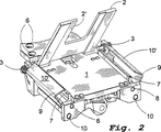
図2はケーシング部品を製造するためのジグを模式的に示している。ジグには配置面に対し下ろされ、それを覆うことができるカバー2を回転させることができる配置面1を有している。カバー2はU字形の陥凹部2‘を持ち、軸3に対し回転でき、ポスト内のベアリング上に取り付けられている。カバーは不図示の下側部にあるフラッグにより制御することができる。配置面1は、残りのディテールを動かすことでネジ穴6を利用し、所定位置の垂直回転テーブル軸上にネジ止めすることができる。第一折りたたみ装置7は軸8の回りを配置面1に接し、90°の角度を形成する位置まで回転することができる。軸10のベアリング上に取り付けられた第二折りたたみ装置9は水平接触部品10により、第一折りたたみ装置7に接触する上縁部の上に置かれ、これを覆う事ができる。
【0013】
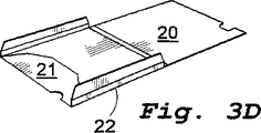
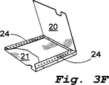
記述し、また図1に模式的に示した様に、図に示した例に類似の六個のジグが回転テーブル内に配置され、そして固定位置間を回転移動している。これらの一つは、図3Aに示す様な折りたたみノッチ付き厚紙加工材を持つマガジンの正面右の挿入位置にある。最上部の加工材は吸い込みカップ付きアームにより取り上げられが、このとき図3Bに示す様にエアノズルが背面部分20を持ち上げ、それからアームが管を作り加工材を折りたたみ(不図示)、その結果折り込み22(図3C)は上向きに90°折り込まれるが管形成から解除されると若干元に戻り、そして同時にフラップ21も若干上向きに折り込まれる。アームは次に図3Cにより形成された加工材を配置面1の上に下ろす(図2)。カバー2が下ろされるが、陥凹部2’のおかげで吸い込みカップは若干残すことができる。これによりフラップ21はカバーによって完全に下方向に押されるようになる。これにより加工材は固定され、吸い込みカップを取り外すことができ、ジグを次のステーションに移動させることができる。第一折りたたみ装置7は図2に示した位置から直立方向に回転し、それにより折り込み22は90°となり、加工材は図3Dに示す形を獲得する。その後第二折りたたみ装置9が配置面と第一折りたたみ装置7に向かって回転する。第二折りたたみ装置9の上部10は第一折りたたみ装置7の上部の上に水平に配置され、その間に厚紙がその間に送り込まれ折り25を形成する。続いて、第二折り込み装置が持ち上げられている間に、ミシンのプレスフット(不図示)に似た活動型固定装置を持つノズルを使い溶融接着剤24を適用する。続いて図3Fに示す様に大型の背面部品20を折り重ね、接着剤が塗られた折り込みフラップに対し押しつけた後、第二折りたたみ装置9を再度加工材上に降ろし、図3Gに示したケーシング25の様な最終形状を得る。回転テーブルの一部が回転している間、接着接合部には第二固定装置がそれを押し下げ固定することで圧が加えられ、その結果溶融接着剤は硬化する。最後に回転テーブルにあるジグのための最終ステーションにて、カバー2はその上に乗せられたケーシング部品と共に軸3−3の回りを約45°上向きに回転し、続いて完成ケーシングが引き出され、回転させられ、コンベアーの上に乗せられ(図2のA2)、スライド部品と組み合わされるポイントに運ばれる。ジグは元の位置に留まり、そこで新しい加工材が配置される。
【0014】
既述の如く、ケーシング用のスライド部品はジグを持つ別の回転テーブル(図1のB)にて製造される。この様なジグは図4に示されており、開口部31と一方の端部に回転テーブルに固定するための固定穴32を持つ配置プレート30、及びもう一方の端部にある陥凹部33より構成される。持ち上げ回転させることができるクランピング装置34が軸35の上に取り付けられており、配置プレート下に強固に配置されているスリーブ36の中に挿入されている。軸35にはスリーブ36とコントロールヘッド38の間に配置されたコイルバネ37によりバネ荷重が加えられており、軸端部には肩が付与されており、コイルバネ37はこの肩に固定されている。異なるステーションでは、クランピング装置34を持ち上げる時、及びそれらを放射線状に回転させる場合、コントロールヘッド38及びそのネジ回しスロット39を利用してクランピング装置34を垂直方向にコントロールすることができる。図4には異なる位置にある2つのクランピング装置34が示されているが、図左手の装置は図に示されていない補助手段により下から上に向かって更に押されている。コントロールされない場合、一部完成したスライド部品はある固定位置から別の固定位置に搬送されることから、クランピング装置はそれらの間に運ばれたものは全てつまみ上げ、プレート30の上に置くだろう。即ち、ジグが動いていない場合には、図1に示した固定位置の一つでコントロールヘッド38による制御が行われる。また、縦トラック40がジグ内に提供され、これが以下詳細記載する完成スライド部品を外に押し出す押出し装置として機能する。
【0015】
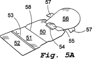
次に図4のジグはスライド部品を折りたたみ、ディスク及び小冊子をスライドケーシング部品内に入れられる部品の上に置くのに利用される。図5Aは厚紙加工材が示されており、折りたたみノッチ58で分離された底プレート50、51、二重折り込みにより底プレートと分離されている蓋フラップ52、固定フラップ55及びフラップ57が付けられた分離プレート56を見ることができる。
【0016】
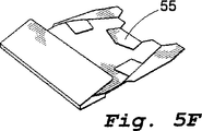
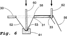
図5Aの厚紙加工材はジグ内の開口部31幅(図4)と一致した幅を有し、また軸35からの距離も加工材の幅より大きいため何ら障害なくプレート30上に置くことができる。厚紙加工品は吸い込みカップアームによりマガジン(図1のB1)より一つずつ吸い取られまず直線縁に合わせ、次に十分な距離を置いて挿入され、折り込みノッチ58をジグ内開口部31の最接近縁正面に正しく配置され、一方固定フラップ55の折り込みノッチ54は陥凹部33の縁に合わせられ、その後クランピング装置34が回転して厚紙の上に下ろされこれを固定する。次のステーションでは(図6の断面図参照)、二重折り込み53の間の距離と同じ幅と加工材の幅に一致した長さを持つヘッドを有するスタンプが開口部31を通り下向きに運び下ろされ、開口部31を通し厚紙をプレスするが、ステーションの下には正確な高さと相補的プロフィールを持った加工台61が提供されており、その結果折り込み58が開口部縁に対し約60°の角度で折り込まれると同時に二重折り込み53が折り込まれる。同時にジグの幅方向の寸法が小さい、上から接近する別の装置62が固定フラップ55を下向きにプレスし、その後加工材は図5Bに示す形状になる。次のステーションで加工材は開口部に押し戻され、その結果織り込み58は開口部31の前方縁に対し織り込まれ(図4)、矯正される。あるいはこの時点では、引き続き小冊子及び場合によっては追加ディスクが図5Cに示す様な位置に置かれる場合に障害にならない様に分離プレート56は若干下方に配置されることもあり、またクランピング装置は小冊子及び随意の追加ディスクを下ろす際に障害になることがあることから、上記プレートが押し下げられている間クランピング装置34を障害にならないように一時的に操作することができる。その後分離プレート56は小冊子及び随意の追加ディスク(図5D、5E)上に折り込まれ、吸い込みカップが提供されたアームを使い図5Eに示す位置にある分離プレート56の上にディスクが配置される。アームがディスクを下ろし全体をまとめて保持している間、次にクランピング装置34を持ち上げ、回転させてディスク57の上にフラップ57を折り込ませ、全体を保持することができ、その後スライド部品は完成させられる。続く工程にて回転テーブルが次の固定位置まで移動する間にプラウイングすることにより、フラップ52は回転ディスク上にて下向きに折り込まれ、一方固定フラップ55は上向きに折り込まれ、その結果ディスク、小冊子及び随意第二ディスクが挿入されている図5Fに示す形状を得ることができる。
【0017】
図1に示される様に、ジグの最後のステーションは完成ケーシング25に対しギャップを持つコンベヤーA2の正面に垂直方向に正確に提供されていることから、ケーシング25の開口部に向かって正確に正面滑垂直方向に位置している。コンベヤーは段階的に送られるため、ジグ及びケーシング部品は最終的には十分な正確性を持って互いの正面に位置するようになる。コンベヤーの分離壁により、約5mmのケーシング部品について全ての作業を行うことができる。
【0018】
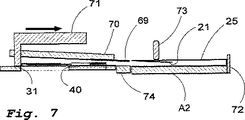
図7の断面図に示すように、ジグ上の完成スライドに向かって下がっている下向き固定装置69及び70が備えられており、これがスライド部品をまとめて保持しているため、ここでクランピング装置34(図4)を取り外すことができる。その後、クロー装置71がトラック40(図4)内に咬み合い、続いてジグからスライド部品を押し出す。本体裏の縁は開口部31の裏縁とほぼ同じレベルに配置されており、そのためトラック40内ではクロー装置71はスライド部品の後ろで咬み合い、次にクロー装置が動くことで前に押し出されるが、その場合下向き固定装置69及び70は、クロー装置71について動くための空間(未表示)を残すように取り付けられる。従って、このスライド部品はケーシング部品25の開口部に向かって送り出されることになり、それは加工台72及びブーム73を使いコンベヤー内の所定位置に固定され、下向きに運ばれる。あるいはジグ及びコンベヤーA2の間の位置にブリッジ部品74が配置され得る。図5Fに示すように、完成スライド部品は面取りされた端側部を持っているため、側方へ若干動くことができるケーシング部品25の小さな配置誤差は、修正されることになり、その結果スライド部品はクロー装置71の連続した動きによって、ケーシング部品内に押し込まれる。その後、下向き固定装置69と70及びクロー装置71は上方に持ち上げられること、そしてこれら装置の何れもが回転テーブルの動きに合わせ回転することはなく、むしろ最終ステーションに留まることから、コンベヤーA2が新しい空のケーシング部品を運び込む最終ステーションの最終位置に、完成スライド部品を持った次のジグが回転することができるようになる。
【0019】
固定フラップがディスク上に折り込まれているスライド部品内の固定フラップ(図5F)が、固定フラップ21の遊離端を通過したその遊離端と共に完成ケーシング部品内に挿入されるとすぐに、続くスライド部品引き出し作業の間にこれら固定フラップは相互に掛け合わされ、それ以上引き抜かれないようにする。その結果ケーシング部品とスライド部品は分割不可能なユニットとなり、同時にディスク、小冊子及び随意の第二ディスクを快適な方法でスライド部品から引き出しまた挿入することができ、公告発明WO/97/38919に記載されている様に停止位置まで引き出すことができる。
【0020】
図示した装置及び厚紙加工品、小冊子及びディスク/複数ディスクを取り上げ、置くための真空吸引カップが装備されたアームに加え、記載の各種作業を実施することを目的として各種ステーション内に機能的装置が提供される。2ステーション間をジグが移動している間に、幾つかの作業を実施することも可能であり、この様な動きはコンピューター制御により実施される。例えば、ケーシング部品を製造している間に、カバー2に関する操作イヤー及び操作イヤーが、下方に配置されている折り込み装置7、9それぞれに関する制御装置(未表示)をジグの動きが回転している間に、カムの表面の手段により作動させることができる。更にスライド部品に関しては、図5B及び図5Cの位置の間にある分離プレート56を、カム表面の手段により下方に回転させ、小冊子及び随意の第二ディスクを下ろす時障害に成らないようにすることができ、更にカム表面の手段を使った同様の方法によりジグが回転している間に、少なくとも図5Dに示す限りに於いて、一方のステーションから別のステーションに折り重ねることができる。
【0021】
注意深く調整された時系列及びコンピューター管理の下、全ての各種作業が実施される。回転テーブルの回転は、ステッピングモーター、可能であればカムベルトを使って回転軸に接続されたものにより実施されることが好ましい。この様な運転手段は下方に位置しており、図示されていない。既に述べた様に、幾つかの折り込み作業は一つのステーションから次のステーションに移動する間に、カム表面を通過する各ジグにより実施され、その間別の装置による別の運動が、コンピューターに信号を送る光フォークの管理の下に、コンピューター制御された空気式シリンダー装置により実施される。速度を調節することで機械上の問題の多くは避けることができ、更にソフトウエアーのソースコードを持たない人にとっては十分複雑であり、それを改変し、そして数量チェックを免れる様なことができないという記録手続きの観点から、最も望ましいソフトウエアー管理が実現される。
【図面の簡単な説明】
【図1】コンパクトディスク及び類似品の包装に適した装置の上から見た詳細な全体図。
【図2】ケーシング部品の製造に関するジグ。
【図3A−G】第一回転テーブルにて実施される場合のケーシング部品に関する段階的折りたたみ工程を示した概略的な透視図。
【図4】スライド部品の製造及び収容用ジグ。
【図5A−F】第二回転テーブルにて実施される場合の、スライド部品に関する段階的折りたたみ工程を示す概略的な透視図。
【図6】スライド部品製造の段階を示した断面図。
【図7】完成したスライディング部品が、どの様にジグから完成したケーシング部品内に直接挿入され、それが完成される中で、スライドパーツに運ばれるかを示した概略断面図。[0001]
(Technical field)
The present invention, as set forth in the preamble of the claims, provides for punching, providing folding notches, folding packaging, and disk-type products, particularly compact discs, prior to the material in the manufacturing process of cardboard or similar Or it is related with the apparatus which accommodates the similar goods.
[0002]
(Background technology)
A device of this type is known from the Swedish patent specification SE-C-508483, and is suitable for standing up a packaging material and placing it in a disc-shaped product, in particular a compact disc. Is a type of packaging material described in the published invention WO / 97/38919 and as a special shape in Swedish patent application number 9900018-1. These packaging materials made from cardboard have many advantages over the more common plastic packaging materials today. In known devices, there are two endless, staged or continuous feed endless conveyors that are arranged to pass through the station in a straight line or to perform many different tasks, and these conveyors Face each other at right angles to assemble casing parts from one conveyor and slide parts from the other conveyor. For this reason, the entire apparatus becomes relatively large. As a result, among other things, the device cannot be transported without being disassembled, requiring both disassembly and assembly operations, and time is wasted.
[0003]
The object of the present invention is small enough to be mounted on a single bed and can be installed and transported in the factory as a unit, for example a standard forklift, except perhaps for a power control cabinet or equivalent. It is an object to provide a device suitable for the above-mentioned purpose, which can be moved as a whole. Therefore, in principle, the device can be shipped to any location in the world using aircraft and ready for factory preparation. Another object is to provide a fast and reliable fixed packaging device. The third objective is to replace the mechanical control and collaborative work by means such as shafts, gears, cam wheels, etc., in order to maximize expandability, and to use a fixed packaging device with a completely computer controlled mechanism. Is to provide.
[0004]
(Disclosure of the Invention)
These and other advantageous objects are achieved for the first time by an apparatus of the type configured as described in the characterizing part of
[0005]
Preferably, at least one of the turntables is provided with a fixed station having a rotation angle interval between each other, and the number per rotation is the same as the number of each jig. Preferably, one unit is assembled per revolution, so that during operation, the rotary tables rotate at a speed such that they cover the same number of revolutions. However, the two rotary tables need not have the same number of jigs.
[0006]
According to the present invention, various work processes such as picking, installation, folding and the like are suitably performed by controlling software in the computer, thereby controlling an electromagnet and a pneumatic or hydraulic control device, a stepping motor, and the like. This provides the special advantage that for the most part the control can be assisted by computers and software, so that the package volume can be tracked. For example, the software can be run such that only a certain number of packaging operations are performed until a new code is sent that encodes a party with the right to use it freely. It is also possible to add a registration from a coded memory or the like, which allows a list by date, time and the number of packages produced per specific case to be drawn. That is, it offers great potential to reduce fraud and unauthorized manufacturing.
[0007]
As described above, the present invention aims to complete a casing part and a slide part from a flat manufacturing process product, respectively, and a rotary table track having a plurality of jigs for providing a disk to the slide part and continuing the parts together. There is. The jig of the casing part is characterized in that it can enter the jig perpendicular to the placement surface and the direction of rotation and has a U-shaped cover that can be placed on the placement surface, the cover being arranged Acting as a “last” placed on the casing manufacturing process placed on the surface, the casing manufacturing process being placed in jigs and equipment in different stations by means of a rotatable device; Folded through a step-by-step process, glued around the cover, and finally peeled off in the same way as the last used in shoe manufacturing, and in the subsequent process, the “last” is replaced with a contained individual part . The special advantage of this jig system over the prior art is that the jig is with the clamping device, can hold solid parts constant and safe even during several station stops, and adhesive (melt adhesive) ), The bonded portions present in the casing parts stopped against the corresponding jig can be squeezed simultaneously.
[0008]
The features of the jigs that contribute to the production of slide parts are that they have a main part including a mounting plate with a square opening and have a clamping device that can be lifted and rotated, which is used as a means for folding and fixing And having a vertical control shaft that can be lifted and rotated, and that they have a spring that pushes the installation plate downward in the axial direction. Preferably they are controlled by means by means of a controller, preferably pneumatically operated, located at different stations. The final work process at the slide part turntable consists of the completed and received slide part being inserted into the finished casing part and transported to the slide part, after which the finished package is carried out.
[0009]
(Best Mode for Carrying Out the Invention)
The invention will be described in detail with reference to means of a non-limiting embodiment and to the drawings.
[0010]
FIG. 1 represents the complete packaging assembly in terms of components, viewed from above. Two rotating devices A and B and an additional peripheral device are included. The turntable A has six jigs that can rotate stepwise around the center, starts from the article supply position A1 in the casing manufacturing process, and then passes stepwise through the turntable that rotates counterclockwise. The casing is unloaded from the conveyor A2 in a completed form. The turntable device B has eight jigs for folding and accommodating slide parts relating to the casing. The workpiece is placed on the jig from the supply unit B1, formed in stages, and a booklet and one or two disks are inserted at different stations. The booklet is supplied from a conveyor belt C by a suction arm (not shown), placed on a two-sheet conveyor, and from there, the booklet is placed on a partially woven slide part while being rotated by 90 °. . Two delivery stations for disks D 'and D, of the type known per se in connection with the manufacture of compact disks, store the disks on the spear. Each station has space for six rotating racks in which spears with disk piles are arranged. Each delivery station receives feeds from these to a level suitable for lifting the top disk using a suction arm (not shown) to lower the disk onto the jig on each D'2 and D2. The capacity of D′ 1 and D1 is maintained.
[0011]
The delivery station D 'is only necessary when inserting two discs, and in D'1 the first disc delivered from D' is directly on the booklet before the partition plate is woven downwards on it. Placed. At station D1, the disc is placed on the partition plate, and while continuing to rotate, the jig reaches the final station (represented by A + B + C + D (+ D ′)), where the slide part is inserted into the casing, Thereafter, the completed packaging moves along the remaining truck A2 and is carried out. As will become clear from the following explanation, there are various control devices around the jig arrangement. From the viewpoint of clarity, in this simplified diagram, plow devices and the like for performing folding work are used. Not shown.
[0012]
FIG. 2 schematically shows a jig for producing casing parts. The jig has a
[0013]
As described and shown schematically in FIG. 1, six jigs similar to the example shown in the figure are placed in the turntable and are rotationally moved between fixed positions. One of these is in the insertion position on the right front of the magazine having a cardboard workpiece with folding notches as shown in FIG. 3A. The uppermost workpiece is picked up by the arm with the suction cup. At this time, as shown in FIG. 3B, the air nozzle lifts the
[0014]
As described above, the slide part for the casing is manufactured by another rotary table having a jig (B in FIG. 1). Such a jig is shown in FIG. 4, and includes an
[0015]
The jig of FIG. 4 is then used to fold the slide part and place the disc and booklet on the part that can be placed in the slide casing part. FIG. 5A shows a cardboard work piece with a
[0016]
5A has a width corresponding to the width of the
[0017]
As shown in FIG. 1, the last station of the jig is accurately provided perpendicular to the front of the conveyor A2 having a gap with respect to the
[0018]
As shown in the cross-sectional view of FIG. 7, there are provided downward fixing
[0019]
As soon as the fixed flap (FIG. 5F) in the slide part with the fixed flap folded over the disc is inserted into the finished casing part with its free end passed through the free end of the fixed
[0020]
In addition to the arm and the vacuum suction cup for picking up and placing the equipment and cardboard products, booklets and disks / multiple disks shown in the figure, there are functional devices in various stations for the purpose of performing the various operations described. Provided. While the jig is moving between the two stations, it is possible to carry out several tasks, such movement being carried out by computer control. For example, while manufacturing the casing parts, the operation ear and the operation ear related to the
[0021]
All the various tasks are performed under carefully coordinated time series and computer management. The rotation of the rotary table is preferably carried out by a stepping motor, preferably connected to the rotary shaft using a cam belt. Such operating means are located below and are not shown. As already mentioned, several folding operations are performed by each jig passing through the cam surface while moving from one station to the next, during which another movement by another device signals the computer. Implemented by a computer-controlled pneumatic cylinder device under the control of a sending optical fork. Adjusting the speed avoids many of the mechanical problems, and is complicated enough for those who don't have the software source code to modify it and not be able to avoid the quantity check From the viewpoint of the recording procedure, the most desirable software management is realized.
[Brief description of the drawings]
FIG. 1 is a detailed overall view from above of an apparatus suitable for packaging compact discs and similar items.
FIG. 2 is a jig relating to the manufacture of casing parts.
FIGS. 3A-G are schematic perspective views showing a stepwise folding process for casing parts when implemented on a first turntable. FIGS.
FIG. 4 shows a jig for manufacturing and housing a slide part.
FIGS. 5A to 5F are schematic perspective views showing a step-by-step folding process for a slide part when implemented on a second rotary table. FIGS.
FIG. 6 is a cross-sectional view showing a stage of manufacturing a slide part.
FIG. 7 is a schematic cross-sectional view showing how a completed sliding part is inserted directly into a completed casing part from a jig and carried to a slide part as it is completed.
Claims (8)
前記装置がケーシング部品を組み立てて取り付けるための第一トラックと、スライド部品を組み立てて少なくとも一枚の円盤状製品をそれぞれの中に入れるための第二トラックと、完成した各ケーシング部品を収容済み完成スライド部品と対にして組み合わせ、完成スライド部品をケーシング部品の中に挿入する手段と、を有する装置において、
第一トラック及び第二トラック(A、B)が回転テーブルを有し、且つ各回転テーブルがその上に取り付けられた複数のジグを有する回転軸を含み、前記ジグは、ケーシング部品及びスライド部品をそれぞれ保持して、段階的に完成させるための保持装置(2、7、9、34)を有し、前記軸は、固定角度位置にあるステーション間でジグを移動させるべく回転可能であり、前記固定角度位置には、完成ケーシング部品をケーシングジグから取り外してスライド部品ジグまで運搬し、完成ケーシング部品が内部に収容済み完成スライド部品を持つ最終位置に向かって回転するように構成されたコンベヤー(A2)が設けられ、前記最終位置に、スライド部品を挿入するための押し出し装置(71)と、スライド部品の挿入端の挿入が完了するまでスライド部品全体を保持するための下方固定装置(70)とが設けられることを特徴とする装置。Folding packaging suitable for one or a plurality of disc-shaped products, in the apparatus for housing, it said packaging is made from the casing working portion and slide the working portion which is punched from the material, the flat tetrahedral casing A slide part that is pushed into the casing and matches the maximum dimension of the disc-shaped product;
A first track for mounting the device is not assembled casing parts, a second track for optionally assembling the sliding parts to put at least one of the disc-shaped products in each respective casing parts form complete Means for paired combination with a housed finished slide part and means for inserting the finished slide part into the casing part ;
Having a first track and a second track (A, B) is a rotary table, and includes a rotating shaft each rotary table has a plurality of jigs mounted thereon, said di grayed, the casing parts and slide parts Each holding and holding devices (2 , 7 , 9 , 34) for completion in stages, the shaft being rotatable to move the jig between stations at fixed angular positions, In the fixed angle position, the conveyor is configured to remove the finished casing part from the casing jig and transport it to the slide part jig so that the finished casing part rotates toward the final position with the finished slide part contained therein. A2) is provided, and the push-out device (71) for inserting the slide part and the insertion of the insertion end of the slide part are completed at the final position. Apparatus characterized by lower fixing device for holding the entire slide part (70) and is provided to.
配置プレート(1)の上に置かれるように回転可能であるとともに、完成ケーシングの内寸法に一致した厚さを持つカバー(2)、
前記配置プレート(1)の側縁に向かって回転して該側縁と直角をなすように接触し、配置プレートからの高さが完成ケーシングの厚さに一致するように形成された第一折りたたみ装置(7)、及び
配置プレートの側縁に向かって、該側縁と接触している第一折りたたみ装置に向かって回転し、第一折りたたみ装置(7)の上端部と水平に接する接触部位(10)を備える第二折りたたみ装置(9)、を有することを特徴とする請求項1に記載の装置。 A positioning plate ( 1 ) with side edges separated from each other by a distance corresponding to the width of the finished casing , the jig for folding the casing parts;
A cover (2) which is rotatable to be placed on the positioning plate (1) and has a thickness corresponding to the inner dimensions of the finished casing;
The pre-contact so as to form the side edge perpendicular to rotate toward the side edges of Sharing, ABS location plate (1), the height from the arrangement plate is formed so as to match the thickness of the finished casing One folding device (7) and a contact that rotates towards the side edge of the arrangement plate towards the first folding device that is in contact with the side edge and is in horizontal contact with the upper end of the first folding device (7) Device according to claim 1, characterized in that it has a second folding device (9) comprising a part (10) .
Applications Claiming Priority (3)
| Application Number | Priority Date | Filing Date | Title |
|---|---|---|---|
| SE9900796A SE513795C2 (en) | 1999-03-05 | 1999-03-05 | Machine for wrapping and filling packaging for disc-shaped products |
| SE9900796-5 | 1999-03-05 | ||
| PCT/SE2000/000415 WO2000053503A1 (en) | 1999-03-05 | 2000-03-02 | Machine for folding and filling of containers, in particular for cd discs and the like |
Publications (3)
| Publication Number | Publication Date |
|---|---|
| JP2002539038A JP2002539038A (en) | 2002-11-19 |
| JP2002539038A5 JP2002539038A5 (en) | 2007-04-26 |
| JP4447792B2 true JP4447792B2 (en) | 2010-04-07 |
Family
ID=20414733
Family Applications (1)
| Application Number | Title | Priority Date | Filing Date |
|---|---|---|---|
| JP2000603951A Expired - Fee Related JP4447792B2 (en) | 1999-03-05 | 2000-03-02 | A device for folding containers such as CD discs, etc. |
Country Status (8)
| Country | Link |
|---|---|
| US (1) | US6609352B1 (en) |
| EP (1) | EP1175345B1 (en) |
| JP (1) | JP4447792B2 (en) |
| AT (1) | ATE252020T1 (en) |
| AU (1) | AU3849800A (en) |
| DE (1) | DE60005944T2 (en) |
| SE (1) | SE513795C2 (en) |
| WO (1) | WO2000053503A1 (en) |
Families Citing this family (8)
| Publication number | Priority date | Publication date | Assignee | Title |
|---|---|---|---|---|
| ITBO20000653A1 (en) * | 2000-11-14 | 2002-05-14 | Sichera Di Sichera Gianni | METHOD FOR INSERTING A COVER SHEET BETWEEN A CLEAR FILM AND A CONTAINER WITH BOOK OPENING AND DEVICE THAT IMPLEMENTS |
| US7076932B2 (en) * | 2003-01-21 | 2006-07-18 | Richard Howard Rubin | Apparatus and method for wrapping |
| US20060025885A1 (en) * | 2004-08-02 | 2006-02-02 | The Form House, Inc. | Apparatus and method for loading data storage devices into carriers |
| DE102006033630A1 (en) | 2006-07-20 | 2008-01-24 | Robert Bosch Gmbh | Method and device for producing a high-precision box |
| USH2266H1 (en) | 2008-12-02 | 2012-02-07 | The United States Of America As Represented By The Secretary Of The Navy | Glue jig to position adhesive-applied specimens |
| US20110030319A1 (en) * | 2009-08-10 | 2011-02-10 | O'malley Martin | Machine |
| US20130180208A1 (en) * | 2012-01-18 | 2013-07-18 | International Microsystems, Inc. (Imi) | Apparatus for loading containers with objects |
| CN116812236B (en) * | 2023-04-19 | 2023-11-14 | 山东劳动职业技术学院(山东劳动技师学院) | Goods fastener is used in commodity circulation transportation of electricity merchant |
Family Cites Families (12)
| Publication number | Priority date | Publication date | Assignee | Title |
|---|---|---|---|---|
| GB1032677A (en) * | 1964-01-25 | 1966-06-15 | Bemrose & Sons Ltd | Improvements in packaging machines |
| DE3829308C1 (en) * | 1988-08-30 | 1989-12-28 | Unilever N.V., Rotterdam, Nl | |
| US5207050A (en) * | 1992-01-15 | 1993-05-04 | Thiele Engineering Company | Apparatus and method for assembling compact disc or media package |
| US5285620A (en) * | 1992-12-11 | 1994-02-15 | Thiele Engineering Company | Apparatus and method for manufacturing a compact disc holder |
| US5694743A (en) * | 1995-08-15 | 1997-12-09 | Beighle; Douglas J. | Book/disc product and method of making the same |
| CN1166032A (en) * | 1995-12-29 | 1997-11-26 | 奎德/技术公司 | Method of packaging computer disks |
| DE19613832C2 (en) * | 1996-04-09 | 1998-12-10 | Heino Ilsemann Verpackungsmasc | Method and device for packaging compact discs |
| US5852915A (en) * | 1996-09-26 | 1998-12-29 | R. R. Donnelley & Sons Company | Method of making compact disc product |
| SE508483C2 (en) * | 1997-02-17 | 1998-10-12 | Sprinter System Ab | Method and apparatus for raising and filling a package |
| US5890346A (en) * | 1997-02-20 | 1999-04-06 | Automated Packaging Systems, Inc. | Disc packaging machine and method |
| US5875614A (en) * | 1997-09-25 | 1999-03-02 | Univenture Inc. | Apparatus and methods for forming flexible packaging containers for discs |
| US6032435A (en) * | 1998-05-05 | 2000-03-07 | Gima S.P.A. | Device for introducing sleeves into cases for compact disc and the like |
-
1999
- 1999-03-05 SE SE9900796A patent/SE513795C2/en not_active IP Right Cessation
-
2000
- 2000-03-02 WO PCT/SE2000/000415 patent/WO2000053503A1/en active IP Right Grant
- 2000-03-02 US US09/936,056 patent/US6609352B1/en not_active Expired - Fee Related
- 2000-03-02 AT AT00917542T patent/ATE252020T1/en not_active IP Right Cessation
- 2000-03-02 DE DE60005944T patent/DE60005944T2/en not_active Expired - Lifetime
- 2000-03-02 JP JP2000603951A patent/JP4447792B2/en not_active Expired - Fee Related
- 2000-03-02 EP EP00917542A patent/EP1175345B1/en not_active Expired - Lifetime
- 2000-03-02 AU AU38498/00A patent/AU3849800A/en not_active Abandoned
Also Published As
| Publication number | Publication date |
|---|---|
| EP1175345A1 (en) | 2002-01-30 |
| DE60005944T2 (en) | 2004-07-22 |
| AU3849800A (en) | 2000-09-28 |
| WO2000053503A1 (en) | 2000-09-14 |
| SE9900796L (en) | 2000-09-06 |
| EP1175345B1 (en) | 2003-10-15 |
| JP2002539038A (en) | 2002-11-19 |
| SE513795C2 (en) | 2000-11-06 |
| US6609352B1 (en) | 2003-08-26 |
| ATE252020T1 (en) | 2003-11-15 |
| SE9900796D0 (en) | 1999-03-05 |
| DE60005944D1 (en) | 2003-11-20 |
Similar Documents
| Publication | Publication Date | Title |
|---|---|---|
| CN101022996B (en) | Modular packing system | |
| JP4447792B2 (en) | A device for folding containers such as CD discs, etc. | |
| SE1651200A1 (en) | Pick and place head with internal vacuum and air pressure supply, system and method | |
| CN109927347A (en) | A kind of automatic peripheral frame moulding process of packing box and equipment | |
| CN210553248U (en) | Automatic frame former that encloses of packing carton | |
| CN107081759B (en) | Flexible assembly system for dished prize disc | |
| US20020062627A1 (en) | Process and machine for fastening objects into a box having a square or rectangular corss-section | |
| US4958478A (en) | Apparatus for storing and supplying end closures for envelopes of cylindrical commodities | |
| JPH0520284B2 (en) | ||
| CN210652044U (en) | Automatic frame forming device that encloses of packing carton | |
| CN212101102U (en) | Automatic blowing device of smart card | |
| JP4644350B2 (en) | Folding box take-out supply device | |
| US6612789B2 (en) | Compact disc shaping apparatus and method | |
| CN212312874U (en) | Box body forming device for one-step forming of surface paper blank plate and side plate | |
| JPH04183533A (en) | Assembly device for cylindrical body | |
| JP2782657B2 (en) | Automatic suspension subunit assembling method and apparatus | |
| CN216423568U (en) | Carton assembling equipment | |
| CN214526739U (en) | Adhesive tape sticking machine | |
| CN116692110A (en) | Packaged product production equipment | |
| CN213229189U (en) | Press and cover device | |
| CN210708138U (en) | Device for disassembling color box | |
| JPH0323453B2 (en) | ||
| JP2001145965A (en) | Apparatus and method for feeding paper pipe | |
| JP2886081B2 (en) | Forming and mounting method of cap for enclosing end face of steel coil | |
| US20090124478A1 (en) | Multi-Direction Carton Setup On A Single Direction Machine |
Legal Events
| Date | Code | Title | Description |
|---|---|---|---|
| A521 | Request for written amendment filed |
Free format text: JAPANESE INTERMEDIATE CODE: A523 Effective date: 20070228 |
|
| A621 | Written request for application examination |
Free format text: JAPANESE INTERMEDIATE CODE: A621 Effective date: 20070228 |
|
| TRDD | Decision of grant or rejection written | ||
| A01 | Written decision to grant a patent or to grant a registration (utility model) |
Free format text: JAPANESE INTERMEDIATE CODE: A01 Effective date: 20091222 |
|
| A01 | Written decision to grant a patent or to grant a registration (utility model) |
Free format text: JAPANESE INTERMEDIATE CODE: A01 |
|
| A61 | First payment of annual fees (during grant procedure) |
Free format text: JAPANESE INTERMEDIATE CODE: A61 Effective date: 20100121 |
|
| FPAY | Renewal fee payment (event date is renewal date of database) |
Free format text: PAYMENT UNTIL: 20130129 Year of fee payment: 3 |
|
| R150 | Certificate of patent or registration of utility model |
Free format text: JAPANESE INTERMEDIATE CODE: R150 |
|
| LAPS | Cancellation because of no payment of annual fees |