JP4440121B2 - 電圧供給回路およびマイクユニット - Google Patents
電圧供給回路およびマイクユニット Download PDFInfo
- Publication number
- JP4440121B2 JP4440121B2 JP2005001381A JP2005001381A JP4440121B2 JP 4440121 B2 JP4440121 B2 JP 4440121B2 JP 2005001381 A JP2005001381 A JP 2005001381A JP 2005001381 A JP2005001381 A JP 2005001381A JP 4440121 B2 JP4440121 B2 JP 4440121B2
- Authority
- JP
- Japan
- Prior art keywords
- voltage
- circuit
- booster circuit
- output
- stage
- Prior art date
- Legal status (The legal status is an assumption and is not a legal conclusion. Google has not performed a legal analysis and makes no representation as to the accuracy of the status listed.)
- Expired - Fee Related
Links
Images


Classifications
-
- H—ELECTRICITY
- H03—ELECTRONIC CIRCUITRY
- H03F—AMPLIFIERS
- H03F3/00—Amplifiers with only discharge tubes or only semiconductor devices as amplifying elements
- H03F3/181—Low frequency amplifiers, e.g. audio preamplifiers
-
- E—FIXED CONSTRUCTIONS
- E01—CONSTRUCTION OF ROADS, RAILWAYS, OR BRIDGES
- E01D—CONSTRUCTION OF BRIDGES, ELEVATED ROADWAYS OR VIADUCTS; ASSEMBLY OF BRIDGES
- E01D11/00—Suspension or cable-stayed bridges
- E01D11/02—Suspension bridges
-
- E—FIXED CONSTRUCTIONS
- E01—CONSTRUCTION OF ROADS, RAILWAYS, OR BRIDGES
- E01D—CONSTRUCTION OF BRIDGES, ELEVATED ROADWAYS OR VIADUCTS; ASSEMBLY OF BRIDGES
- E01D19/00—Structural or constructional details of bridges
- E01D19/10—Railings; Protectors against smoke or gases, e.g. of locomotives; Maintenance travellers; Fastening of pipes or cables to bridges
- E01D19/103—Parapets, railings ; Guard barriers or road-bridges
-
- E—FIXED CONSTRUCTIONS
- E01—CONSTRUCTION OF ROADS, RAILWAYS, OR BRIDGES
- E01D—CONSTRUCTION OF BRIDGES, ELEVATED ROADWAYS OR VIADUCTS; ASSEMBLY OF BRIDGES
- E01D19/00—Structural or constructional details of bridges
- E01D19/16—Suspension cables; Cable clamps for suspension cables ; Pre- or post-stressed cables
-
- H—ELECTRICITY
- H03—ELECTRONIC CIRCUITRY
- H03F—AMPLIFIERS
- H03F1/00—Details of amplifiers with only discharge tubes, only semiconductor devices or only unspecified devices as amplifying elements
- H03F1/02—Modifications of amplifiers to raise the efficiency, e.g. gliding Class A stages, use of an auxiliary oscillation
- H03F1/0205—Modifications of amplifiers to raise the efficiency, e.g. gliding Class A stages, use of an auxiliary oscillation in transistor amplifiers
- H03F1/0211—Modifications of amplifiers to raise the efficiency, e.g. gliding Class A stages, use of an auxiliary oscillation in transistor amplifiers with control of the supply voltage or current
-
- H—ELECTRICITY
- H03—ELECTRONIC CIRCUITRY
- H03F—AMPLIFIERS
- H03F1/00—Details of amplifiers with only discharge tubes, only semiconductor devices or only unspecified devices as amplifying elements
- H03F1/02—Modifications of amplifiers to raise the efficiency, e.g. gliding Class A stages, use of an auxiliary oscillation
- H03F1/0205—Modifications of amplifiers to raise the efficiency, e.g. gliding Class A stages, use of an auxiliary oscillation in transistor amplifiers
- H03F1/0261—Modifications of amplifiers to raise the efficiency, e.g. gliding Class A stages, use of an auxiliary oscillation in transistor amplifiers with control of the polarisation voltage or current, e.g. gliding Class A
Description
PA音響システム:工学図書:平成8年度版
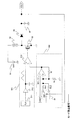
図1は、本発明の実施の形態1のコンデンサマイクユニットを示すブロック図である。実施の形態1のコンデンサマイクユニットは、電圧供給回路1、コンデンサマイク2、増幅回路3、キャパシタ4、抵抗5、6、電源7を有している。
実施の形態2では、昇圧回路21としてFET方式のチャージポンプ回路が用いられている。その他の構成は実施の形態1と同じであるためその説明を省略する。実施の形態1と同様に、このチャージポンプ回路には電圧選択部として、モード指定信号に基づいて動作するスイッチが設けられている。実施の形態2では電源昇圧部であるチャージポンプの構成が異なっているのみであるため、FET方式のチャージポンプ回路を中心に昇圧回路21を説明する。
実施の形態3では、昇圧回路21としてDC/DCコンバータが用いられている。その他の構成に関しては実施の形態1と同様であるため、以下、昇圧回路21についてのみ説明する。この実施の形態では電圧選択部として、モード指定信号に基づいて入力抵抗を変更するスイッチが設けられている。
2 コンデンサマイク
3 増幅回路
4 キャパシタ
5、6 抵抗
7 電源
21 昇圧回路
22 レギュレータ部
221 非反転増幅器
222 基準電圧源
23 出力電圧設定部
231、232 帰還抵抗部
233 モード設定部
30 電圧選択部
31 電源
33、34 インバータ
35 平滑コンデンサ
36 整流ダイオード
37 1倍昇圧回路
40 電圧選択部
41 電源
43、44 インバータ
44 インバータ
46 平滑コンデンサ
47 1倍昇圧回路
50 電圧選択部
51 電源
52 コイル
53 スイッチングトランジスタ
Claims (18)
- 電源電圧を昇圧した電圧を出力する昇圧回路と、
前記昇圧回路によって出力された電圧を電源として動作し、供給されるバイアス電圧の値に応じて感度が切り替わるセンサに対して、基準電圧を非反転増幅した電圧を当該バイアス電圧として供給する増幅器とを有し、
前記昇圧回路は、前記センサの感度を指定する制御信号に基づいて出力する電圧値が設定されることを特徴とする電圧供給回路。 - 前記昇圧回路は、
電源電圧を昇圧する電源昇圧部と、
前記センサの感度を指定する制御信号に基づいて出力する電圧値を選択する電圧選択部とを有することを特徴とする請求項1に記載の電圧供給回路。 - 前記非反転増幅動作における前記増幅器の増幅率を抵抗比により決定する帰還抵抗部をさらに有し、当該抵抗比は前記センサのバイアス電圧の設定値に応じて決定されること特徴とする請求項1又は2に記載の電圧供給回路。
- 前記帰還抵抗部の抵抗値が前記センサの感度を指定する制御信号に応じて決定されることを特徴とする請求項3に記載の電圧供給回路。
- 前記帰還抵抗部は、少なくとも第1の帰還抵抗部および第2の帰還抵抗部を有し、前記センサの感度を指定する制御信号に基づいて、前記第1の帰還抵抗部あるいは第2の帰還抵抗部が前記増幅器に対する帰還抵抗として選択されることを特徴とする請求項3あるいは4に記載の電圧供給回路。
- バイアス電圧が供給されるマイクと、
電源電圧を昇圧した電圧を出力する昇圧回路と、
前記昇圧回路によって出力された電圧を電源として動作し、供給されるバイアス電圧の値に応じて感度が切り替わる前記マイクに対して、基準電圧を非反転増幅した電圧を当該バイアス電圧として供給する増幅器とを有し、
前記昇圧回路は、前記マイクの感度を指定する制御信号に基づいて出力する電圧値が設定されることを特徴とするマイクユニット。 - 前記昇圧回路は、
電源電圧を昇圧する電源昇圧部と、
前記マイクの感度を指定する信号に基づいて出力する電圧値を選択する電圧選択部とを有することを特徴とする請求項6に記載のマイクユニット。 - センサの感度を指定する制御信号に基づいて前記センサに供給するバイアス電圧を設定し、出力する設定回路を備え、
前記設定回路は、
前記センサに前記バイアス電圧を供給する増幅器と、
電源電圧を昇圧した電圧を、前記増幅器を動作させる電源として出力する昇圧回路と、を備えた電圧供給回路。 - 前記設定回路は、基準電圧を生成し前記増幅器の非反転入力端子に供給する基準電圧生成回路を備え、
前記増幅回路は、当該基準電圧を非反転増幅した電圧を前記バイアス電圧として出力することを特徴とする請求項8に記載の電圧供給回路。 - 前記設定回路は、前記増幅器の増幅率を抵抗比により制御する帰還抵抗部を備えることを特徴とする請求項9に記載の電圧供給回路。
- 前記設定回路は、前記増幅器の反転入力端子と前記増幅器の出力端との間に接続された帰還抵抗部を備えることを特徴とする請求項10に記載の電圧供給回路。
- 前記帰還抵抗部は、少なくとも第1の帰還抵抗部および第2の帰還抵抗部を備え、前記センサの感度を指定する制御信号に基づいて、前記第1の帰還抵抗部あるいは第2の帰還抵抗部が前記増幅器に対する帰還抵抗として選択されることを特徴とする請求項10に記載の電圧供給回路。
- 前記センサは、前記バイアス電圧を一端に受け他端が第1の電源ラインに接続されたコンデンサマイクであることを特徴とする請求項8に記載の電圧供給回路。
- 請求項13に記載の電圧供給回路と、
前記第1の電源ラインと第2の電源ラインとの間に接続されたトランジスタと、
前記トランジスタの制御端子と前記コンデンサマイクの前記一端との間に接続されたキャパシタと、を備えたセンサユニット。 - 前記昇圧回路は、1つのダイオードと1つのキャパシタからなる1倍昇圧回路を複数接続したチャージポンプ回路により構成されることを特徴とする請求項8に記載の電圧供給回路。
- 前記昇圧回路は、複数の昇圧部から構成され、前記センサの感度を指定する制御信号に基づいて前記複数の昇圧部から対応する昇圧部を選択し前記出力電圧のもとになる昇圧電圧を生成することを特徴とする請求項8に記載の電圧供給回路。
- 前記チャージポンプ回路は、奇数段の1倍昇圧回路の入力端子は偶数段の1倍昇圧回路
の出力端子に接続され、前記奇数段の1倍昇圧回路の制御端子は第1のインバータの出力
端子に接続され、前記偶数段の1倍昇圧回路の入力端子は前記奇数段の1倍昇圧回路の出
力端子に接続され、前記偶数段の1倍昇圧回路の制御端子は第2のインバータの出力端子
に接続され、
N段目の1倍昇圧回路の出力端子とN+1段目の1倍昇圧回路の入力端子との間に第1
スイッチ、N−1段目の1倍昇圧回路の制御端子とN+1段目の1倍昇圧回路の制御端子
の間に第2スイッチ、N段目の1倍昇圧回路の制御端子と、N+2段目の1倍昇圧回路の
制御端子の間に第3スイッチ、チャージポンプ回路の最終段の整流ダイオードのアノード
端子とその前段の出力端子との間に第4スイッチが設けられ、
前記第1スイッチと前記第4スイッチを接続するように配線が設けられ、
前記第1スイッチは、前記センサの感度を指定する信号に基づいて次段の1倍昇圧回路
の入力端子あるいは前記配線に接続され、
前記第4スイッチは、前記センサの感度を指定する信号に基づいて前段の1倍昇圧回路
の出力端子あるいは前記配線に接続され、
前記第2スイッチおよび前記第3スイッチは、前記センサの感度を指定する信号に基づ
いてオン・オフすることにより昇圧動作を行うことを特徴とする請求項15に記載の電圧供給回路。 - 前記基準電圧生成回路は、バンドギャップ回路であることを特徴とする請求項9に記載の電圧供給回路。
Priority Applications (4)
| Application Number | Priority Date | Filing Date | Title |
|---|---|---|---|
| JP2005001381A JP4440121B2 (ja) | 2005-01-06 | 2005-01-06 | 電圧供給回路およびマイクユニット |
| US11/325,346 US7864970B2 (en) | 2005-01-06 | 2006-01-05 | Voltage supply circuit and microphone unit |
| KR1020060001626A KR100760877B1 (ko) | 2005-01-06 | 2006-01-06 | 전압 공급 회로 및 마이크로폰 유닛 |
| CN2006100057486A CN1801590B (zh) | 2005-01-06 | 2006-01-06 | 电压供应电路和扩音器单元 |
Applications Claiming Priority (1)
| Application Number | Priority Date | Filing Date | Title |
|---|---|---|---|
| JP2005001381A JP4440121B2 (ja) | 2005-01-06 | 2005-01-06 | 電圧供給回路およびマイクユニット |
Publications (3)
| Publication Number | Publication Date |
|---|---|
| JP2006191360A JP2006191360A (ja) | 2006-07-20 |
| JP2006191360A5 JP2006191360A5 (ja) | 2006-12-14 |
| JP4440121B2 true JP4440121B2 (ja) | 2010-03-24 |
Family
ID=36640476
Family Applications (1)
| Application Number | Title | Priority Date | Filing Date |
|---|---|---|---|
| JP2005001381A Expired - Fee Related JP4440121B2 (ja) | 2005-01-06 | 2005-01-06 | 電圧供給回路およびマイクユニット |
Country Status (4)
| Country | Link |
|---|---|
| US (1) | US7864970B2 (ja) |
| JP (1) | JP4440121B2 (ja) |
| KR (1) | KR100760877B1 (ja) |
| CN (1) | CN1801590B (ja) |
Families Citing this family (59)
| Publication number | Priority date | Publication date | Assignee | Title |
|---|---|---|---|---|
| US7356151B2 (en) * | 2004-03-30 | 2008-04-08 | Akg Acoustic Gmbh | Microphone system |
| US7728663B2 (en) * | 2006-06-22 | 2010-06-01 | Sige Semiconductor Inc. | Integrated implementation of a voltage boost follower and method therefor |
| US8027489B1 (en) * | 2006-07-07 | 2011-09-27 | Analog Devices, Inc. | Multi-voltage biasing system with over-voltage protection |
| US8077878B2 (en) * | 2006-07-26 | 2011-12-13 | Qualcomm Incorporated | Low-power on-chip headset switch detection |
| JP2008083850A (ja) * | 2006-09-26 | 2008-04-10 | Nec Electronics Corp | レギュレータ回路 |
| KR101369398B1 (ko) * | 2007-01-15 | 2014-03-04 | 삼성디스플레이 주식회사 | 액정 표시 장치 및 그의 구동 방법 |
| US8456450B2 (en) * | 2007-06-28 | 2013-06-04 | Apple Inc. | Systems and methods for impedance stabilization |
| US8335328B2 (en) * | 2007-10-24 | 2012-12-18 | Winbond Electronics Corporation | Programmable integrated microphone interface circuit |
| US8401208B2 (en) * | 2007-11-14 | 2013-03-19 | Infineon Technologies Ag | Anti-shock methods for processing capacitive sensor signals |
| JP2009225100A (ja) | 2008-03-17 | 2009-10-01 | Nec Electronics Corp | 半導体集積回路及びコンデンサ・マイクロフォン |
| GB2466785B (en) * | 2008-12-30 | 2011-06-08 | Wolfson Microelectronics Plc | Apparatus and method for testing a capacitive transducer and/or associated electronic circuitry |
| JP2010198570A (ja) * | 2009-02-27 | 2010-09-09 | Panasonic Corp | 電圧供給回路 |
| US8233643B1 (en) * | 2010-03-23 | 2012-07-31 | Fiberplex Technologies, LLC | System and method for amplifying low level signals provided on electrical supply power |
| US9431974B2 (en) | 2010-04-19 | 2016-08-30 | Qorvo Us, Inc. | Pseudo-envelope following feedback delay compensation |
| EP2561611B1 (en) | 2010-04-19 | 2015-01-14 | RF Micro Devices, Inc. | Pseudo-envelope following power management system |
| US9099961B2 (en) | 2010-04-19 | 2015-08-04 | Rf Micro Devices, Inc. | Output impedance compensation of a pseudo-envelope follower power management system |
| US8494185B2 (en) * | 2010-07-18 | 2013-07-23 | Bose Corporation | Electro-acoustic transducer tuning and data storage |
| US9215529B2 (en) * | 2010-07-18 | 2015-12-15 | Bose Corporation | Multi-mode audio device interfacing |
| US8494184B2 (en) * | 2010-07-18 | 2013-07-23 | Bose Corporation | Digital data transfer via audio signal conductors |
| US9954436B2 (en) | 2010-09-29 | 2018-04-24 | Qorvo Us, Inc. | Single μC-buckboost converter with multiple regulated supply outputs |
| DE102011002937A1 (de) * | 2011-01-20 | 2012-07-26 | Ford Global Technologies, Llc | Partikelsensor, Abgassystem und Verfahren zum Bestimmen von Partikeln im Abgas |
| US9379667B2 (en) | 2011-05-05 | 2016-06-28 | Rf Micro Devices, Inc. | Multiple power supply input parallel amplifier based envelope tracking |
| US9246460B2 (en) | 2011-05-05 | 2016-01-26 | Rf Micro Devices, Inc. | Power management architecture for modulated and constant supply operation |
| US9668076B2 (en) * | 2011-06-21 | 2017-05-30 | Apple Inc. | Microphone headset failure detecting and reporting |
| US9263996B2 (en) | 2011-07-20 | 2016-02-16 | Rf Micro Devices, Inc. | Quasi iso-gain supply voltage function for envelope tracking systems |
| CN103988406B (zh) | 2011-10-26 | 2017-03-01 | Qorvo美国公司 | 射频(rf)开关转换器以及使用rf开关转换器的rf放大装置 |
| US9484797B2 (en) | 2011-10-26 | 2016-11-01 | Qorvo Us, Inc. | RF switching converter with ripple correction |
| US9515621B2 (en) | 2011-11-30 | 2016-12-06 | Qorvo Us, Inc. | Multimode RF amplifier system |
| US9250643B2 (en) | 2011-11-30 | 2016-02-02 | Rf Micro Devices, Inc. | Using a switching signal delay to reduce noise from a switching power supply |
| US9280163B2 (en) | 2011-12-01 | 2016-03-08 | Rf Micro Devices, Inc. | Average power tracking controller |
| US9256234B2 (en) | 2011-12-01 | 2016-02-09 | Rf Micro Devices, Inc. | Voltage offset loop for a switching controller |
| US9041365B2 (en) | 2011-12-01 | 2015-05-26 | Rf Micro Devices, Inc. | Multiple mode RF power converter |
| US9494962B2 (en) | 2011-12-02 | 2016-11-15 | Rf Micro Devices, Inc. | Phase reconfigurable switching power supply |
| JP5979855B2 (ja) * | 2011-12-06 | 2016-08-31 | 株式会社オーディオテクニカ | コンデンサマイクロホン |
| US9813036B2 (en) | 2011-12-16 | 2017-11-07 | Qorvo Us, Inc. | Dynamic loadline power amplifier with baseband linearization |
| US9298198B2 (en) | 2011-12-28 | 2016-03-29 | Rf Micro Devices, Inc. | Noise reduction for envelope tracking |
| US8674751B2 (en) * | 2012-04-16 | 2014-03-18 | Taiwan Semiconductor Manufacturing Co., Ltd. | Reference generation in an integrated circuit device |
| US9627975B2 (en) | 2012-11-16 | 2017-04-18 | Qorvo Us, Inc. | Modulated power supply system and method with automatic transition between buck and boost modes |
| US9929696B2 (en) | 2013-01-24 | 2018-03-27 | Qorvo Us, Inc. | Communications based adjustments of an offset capacitive voltage |
| US9479118B2 (en) | 2013-04-16 | 2016-10-25 | Rf Micro Devices, Inc. | Dual instantaneous envelope tracking |
| CN104167769B (zh) * | 2013-05-16 | 2016-08-03 | 海洋王(东莞)照明科技有限公司 | 一种扩展电池输出电压电路及电子设备 |
| CN104168529B (zh) * | 2013-05-17 | 2018-08-28 | 上海耐普微电子有限公司 | 多模式的微机械麦克风 |
| US9374005B2 (en) * | 2013-08-13 | 2016-06-21 | Rf Micro Devices, Inc. | Expanded range DC-DC converter |
| CN108449057A (zh) | 2013-09-12 | 2018-08-24 | 意法半导体研发(深圳)有限公司 | 音频设备中去除pop噪声的方法与电路 |
| JP2015115881A (ja) * | 2013-12-13 | 2015-06-22 | 株式会社東芝 | 差動増幅回路およびマイクアンプシステム |
| US9614476B2 (en) | 2014-07-01 | 2017-04-04 | Qorvo Us, Inc. | Group delay calibration of RF envelope tracking |
| US9948240B2 (en) | 2015-07-01 | 2018-04-17 | Qorvo Us, Inc. | Dual-output asynchronous power converter circuitry |
| US9912297B2 (en) | 2015-07-01 | 2018-03-06 | Qorvo Us, Inc. | Envelope tracking power converter circuitry |
| WO2017021929A1 (en) * | 2015-08-05 | 2017-02-09 | Wizedsp Ltd. | Ultra-low-power and low noise microphone for acoustic communication |
| JP6656660B2 (ja) * | 2016-02-12 | 2020-03-04 | 国立大学法人東北大学 | 電圧調整回路 |
| US9973147B2 (en) | 2016-05-10 | 2018-05-15 | Qorvo Us, Inc. | Envelope tracking power management circuit |
| US10530303B2 (en) * | 2016-05-25 | 2020-01-07 | Cirrus Logic, Inc. | Multi-phase power converter system using multiple amplifier integrated circuits |
| TWI727034B (zh) * | 2016-06-24 | 2021-05-11 | 日商東京計器股份有限公司 | 增幅裝置 |
| US10298123B2 (en) * | 2017-06-06 | 2019-05-21 | Infineon Technologies Austria Ag | Power supply control and use of generated ramp signal to control activation |
| US10674296B2 (en) * | 2017-07-28 | 2020-06-02 | Cirrus Logic, Inc. | Microphone bias apparatus and method |
| CN107371100B (zh) * | 2017-09-14 | 2020-02-28 | 珠海全志科技股份有限公司 | 一种麦克风偏置驱动电路 |
| US10476437B2 (en) | 2018-03-15 | 2019-11-12 | Qorvo Us, Inc. | Multimode voltage tracker circuit |
| JP2019208128A (ja) * | 2018-05-29 | 2019-12-05 | ヤマハ株式会社 | 信号伝送回路及び信号伝送方法 |
| US20230188038A1 (en) * | 2021-12-09 | 2023-06-15 | Renesas Electronics America Inc. | Regulator booster |
Family Cites Families (15)
| Publication number | Priority date | Publication date | Assignee | Title |
|---|---|---|---|---|
| JPS58103291A (ja) | 1981-12-15 | 1983-06-20 | Matsushita Electric Ind Co Ltd | コンデンサ型マイクロホン |
| US4617555A (en) * | 1985-04-17 | 1986-10-14 | Data Distribution Devices, Inc. | Receiver for audible alarm |
| JPS6324789A (ja) | 1986-07-16 | 1988-02-02 | Sanyo Electric Co Ltd | リモ−トコントロ−ル装置 |
| US5239579A (en) * | 1991-01-04 | 1993-08-24 | Schuh Peter O | Adaptive amplifier circuit |
| US6195437B1 (en) * | 1997-09-30 | 2001-02-27 | Compaq Computer Corporation | Method and apparatus for independent gain control of a microphone and speaker for a speakerphone mode and a non-speakerphone audio mode of a computer system |
| JP4227679B2 (ja) | 1998-05-07 | 2009-02-18 | 株式会社オーディオテクニカ | インピーダンス変換器 |
| US7003127B1 (en) * | 1999-01-07 | 2006-02-21 | Sarnoff Corporation | Hearing aid with large diaphragm microphone element including a printed circuit board |
| JP2000217188A (ja) | 1999-01-20 | 2000-08-04 | Nec Niigata Ltd | コンデンサマイクロフォン接続回路 |
| JP2001102875A (ja) * | 1999-10-01 | 2001-04-13 | Hosiden Corp | 半導体増幅回路及び半導体エレクトレットコンデンサマイクロホン |
| KR100486868B1 (ko) * | 2002-07-30 | 2005-05-03 | 주식회사 비에스이 | 증폭기를 내장한 콘덴서 마이크로폰 |
| KR100502171B1 (ko) * | 2002-07-30 | 2005-07-22 | 주식회사 비에스이 | 저전압 인가형 콘덴서 마이크로폰 |
| US7787642B2 (en) * | 2003-07-17 | 2010-08-31 | Massachusetts Institute Of Technology | Low-power high-PSRR current-mode microphone pre-amplifier system and method |
| US7391873B2 (en) * | 2003-12-01 | 2008-06-24 | Audioasics A/S | Microphone with voltage pump |
| EP1553696B1 (en) * | 2004-01-12 | 2008-10-08 | Sonion A/S | Amplifier circuit for capacitive transducers |
| EP1599067B1 (en) * | 2004-05-21 | 2013-05-01 | Epcos Pte Ltd | Detection and control of diaphragm collapse in condenser microphones |
-
2005
- 2005-01-06 JP JP2005001381A patent/JP4440121B2/ja not_active Expired - Fee Related
-
2006
- 2006-01-05 US US11/325,346 patent/US7864970B2/en not_active Expired - Fee Related
- 2006-01-06 CN CN2006100057486A patent/CN1801590B/zh not_active Expired - Fee Related
- 2006-01-06 KR KR1020060001626A patent/KR100760877B1/ko not_active IP Right Cessation
Also Published As
| Publication number | Publication date |
|---|---|
| KR100760877B1 (ko) | 2007-09-21 |
| CN1801590B (zh) | 2010-10-13 |
| KR20060080892A (ko) | 2006-07-11 |
| CN1801590A (zh) | 2006-07-12 |
| JP2006191360A (ja) | 2006-07-20 |
| US20060147062A1 (en) | 2006-07-06 |
| US7864970B2 (en) | 2011-01-04 |
Similar Documents
| Publication | Publication Date | Title |
|---|---|---|
| JP4440121B2 (ja) | 電圧供給回路およびマイクユニット | |
| KR100768014B1 (ko) | 전압 공급 회로 및 이를 구비한 마이크로폰 유닛 | |
| JP2006191360A5 (ja) | ||
| JP5287030B2 (ja) | Dc−dcコンバータおよび制御方法 | |
| JP4791094B2 (ja) | 電源回路 | |
| KR100695713B1 (ko) | 승강압형 dc-dc 컨버터, 승강압형 dc-dc 컨버터의제어 회로, 승강압형 dc-dc 컨버터의 제어 방법 | |
| JP4390716B2 (ja) | 電圧供給回路、マイクユニットおよびマイクユニットの感度調整方法 | |
| JP4693047B2 (ja) | 電源回路 | |
| US7292016B2 (en) | Buck/boost DC-DC converter control circuit with input voltage detection | |
| JP2007043861A (ja) | 電源装置及びこれを用いた電気機器 | |
| JP2007043862A (ja) | ソフトスタート回路、電源装置、電気機器 | |
| KR20090038929A (ko) | 다출력 전원 장치 | |
| JPWO2006085632A1 (ja) | 電源回路、及び携帯機器 | |
| JP2007202281A (ja) | 電源回路 | |
| JP2009088426A (ja) | 駆動回路 | |
| KR20150074651A (ko) | 전하 펌프 회로의 구동 회로 및 이를 포함하는 전하 펌프 시스템 | |
| JP2008035297A (ja) | 電源回路装置及びこの電源回路装置を備えた電子機器 | |
| JP2014207820A (ja) | スイッチングレギュレータおよびその制御回路、それを用いた電子機器 | |
| JP4848692B2 (ja) | 昇圧電源回路及び昇圧方法 | |
| JP2020028172A (ja) | 電源供給回路 | |
| JP5104336B2 (ja) | 可変容量回路、誤差増幅回路、およびスイッチング電源 | |
| JP4072148B2 (ja) | 演算増幅器 | |
| JP2005020922A (ja) | チャージポンプ回路 | |
| JP5055982B2 (ja) | ソフトスタート回路及びこれを用いた集積回路装置 | |
| JP3913364B2 (ja) | 増幅回路 |
Legal Events
| Date | Code | Title | Description |
|---|---|---|---|
| A521 | Written amendment |
Free format text: JAPANESE INTERMEDIATE CODE: A523 Effective date: 20061031 |
|
| A621 | Written request for application examination |
Free format text: JAPANESE INTERMEDIATE CODE: A621 Effective date: 20071214 |
|
| A977 | Report on retrieval |
Free format text: JAPANESE INTERMEDIATE CODE: A971007 Effective date: 20090526 |
|
| A131 | Notification of reasons for refusal |
Free format text: JAPANESE INTERMEDIATE CODE: A131 Effective date: 20090602 |
|
| A521 | Written amendment |
Free format text: JAPANESE INTERMEDIATE CODE: A523 Effective date: 20090723 |
|
| A131 | Notification of reasons for refusal |
Free format text: JAPANESE INTERMEDIATE CODE: A131 Effective date: 20090908 |
|
| A521 | Written amendment |
Free format text: JAPANESE INTERMEDIATE CODE: A523 Effective date: 20091104 |
|
| TRDD | Decision of grant or rejection written | ||
| A01 | Written decision to grant a patent or to grant a registration (utility model) |
Free format text: JAPANESE INTERMEDIATE CODE: A01 Effective date: 20091215 |
|
| A01 | Written decision to grant a patent or to grant a registration (utility model) |
Free format text: JAPANESE INTERMEDIATE CODE: A01 |
|
| A61 | First payment of annual fees (during grant procedure) |
Free format text: JAPANESE INTERMEDIATE CODE: A61 Effective date: 20100106 |
|
| FPAY | Renewal fee payment (event date is renewal date of database) |
Free format text: PAYMENT UNTIL: 20130115 Year of fee payment: 3 |
|
| R150 | Certificate of patent or registration of utility model |
Free format text: JAPANESE INTERMEDIATE CODE: R150 |
|
| FPAY | Renewal fee payment (event date is renewal date of database) |
Free format text: PAYMENT UNTIL: 20130115 Year of fee payment: 3 |
|
| S533 | Written request for registration of change of name |
Free format text: JAPANESE INTERMEDIATE CODE: R313533 |
|
| FPAY | Renewal fee payment (event date is renewal date of database) |
Free format text: PAYMENT UNTIL: 20130115 Year of fee payment: 3 |
|
| R350 | Written notification of registration of transfer |
Free format text: JAPANESE INTERMEDIATE CODE: R350 |
|
| FPAY | Renewal fee payment (event date is renewal date of database) |
Free format text: PAYMENT UNTIL: 20130115 Year of fee payment: 3 |
|
| FPAY | Renewal fee payment (event date is renewal date of database) |
Free format text: PAYMENT UNTIL: 20140115 Year of fee payment: 4 |
|
| LAPS | Cancellation because of no payment of annual fees |