JP4436152B2 - Air conditioner - Google Patents
Air conditioner Download PDFInfo
- Publication number
- JP4436152B2 JP4436152B2 JP2004038595A JP2004038595A JP4436152B2 JP 4436152 B2 JP4436152 B2 JP 4436152B2 JP 2004038595 A JP2004038595 A JP 2004038595A JP 2004038595 A JP2004038595 A JP 2004038595A JP 4436152 B2 JP4436152 B2 JP 4436152B2
- Authority
- JP
- Japan
- Prior art keywords
- compression
- compression mechanism
- capacity
- evaporator
- feedforward
- Prior art date
- Legal status (The legal status is an assumption and is not a legal conclusion. Google has not performed a legal analysis and makes no representation as to the accuracy of the status listed.)
- Expired - Fee Related
Links
Images


Classifications
-
- B—PERFORMING OPERATIONS; TRANSPORTING
- B60—VEHICLES IN GENERAL
- B60H—ARRANGEMENTS OF HEATING, COOLING, VENTILATING OR OTHER AIR-TREATING DEVICES SPECIALLY ADAPTED FOR PASSENGER OR GOODS SPACES OF VEHICLES
- B60H1/00—Heating, cooling or ventilating [HVAC] devices
- B60H1/32—Cooling devices
- B60H1/3204—Cooling devices using compression
- B60H1/3205—Control means therefor
- B60H1/3211—Control means therefor for increasing the efficiency of a vehicle refrigeration cycle
-
- B—PERFORMING OPERATIONS; TRANSPORTING
- B60—VEHICLES IN GENERAL
- B60H—ARRANGEMENTS OF HEATING, COOLING, VENTILATING OR OTHER AIR-TREATING DEVICES SPECIALLY ADAPTED FOR PASSENGER OR GOODS SPACES OF VEHICLES
- B60H1/00—Heating, cooling or ventilating [HVAC] devices
- B60H1/32—Cooling devices
- B60H1/3204—Cooling devices using compression
- B60H1/3205—Control means therefor
- B60H1/3208—Vehicle drive related control of the compressor drive means, e.g. for fuel saving purposes
-
- B—PERFORMING OPERATIONS; TRANSPORTING
- B60—VEHICLES IN GENERAL
- B60H—ARRANGEMENTS OF HEATING, COOLING, VENTILATING OR OTHER AIR-TREATING DEVICES SPECIALLY ADAPTED FOR PASSENGER OR GOODS SPACES OF VEHICLES
- B60H1/00—Heating, cooling or ventilating [HVAC] devices
- B60H1/32—Cooling devices
- B60H2001/3269—Cooling devices output of a control signal
- B60H2001/327—Cooling devices output of a control signal related to a compressing unit
-
- F—MECHANICAL ENGINEERING; LIGHTING; HEATING; WEAPONS; BLASTING
- F25—REFRIGERATION OR COOLING; COMBINED HEATING AND REFRIGERATION SYSTEMS; HEAT PUMP SYSTEMS; MANUFACTURE OR STORAGE OF ICE; LIQUEFACTION SOLIDIFICATION OF GASES
- F25B—REFRIGERATION MACHINES, PLANTS OR SYSTEMS; COMBINED HEATING AND REFRIGERATION SYSTEMS; HEAT PUMP SYSTEMS
- F25B2400/00—General features or devices for refrigeration machines, plants or systems, combined heating and refrigeration systems or heat-pump systems, i.e. not limited to a particular subgroup of F25B
- F25B2400/07—Details of compressors or related parts
- F25B2400/075—Details of compressors or related parts with parallel compressors
- F25B2400/0751—Details of compressors or related parts with parallel compressors the compressors having different capacities
-
- F—MECHANICAL ENGINEERING; LIGHTING; HEATING; WEAPONS; BLASTING
- F25—REFRIGERATION OR COOLING; COMBINED HEATING AND REFRIGERATION SYSTEMS; HEAT PUMP SYSTEMS; MANUFACTURE OR STORAGE OF ICE; LIQUEFACTION SOLIDIFICATION OF GASES
- F25B—REFRIGERATION MACHINES, PLANTS OR SYSTEMS; COMBINED HEATING AND REFRIGERATION SYSTEMS; HEAT PUMP SYSTEMS
- F25B2600/00—Control issues
- F25B2600/02—Compressor control
- F25B2600/025—Compressor control by controlling speed
- F25B2600/0253—Compressor control by controlling speed with variable speed
-
- F—MECHANICAL ENGINEERING; LIGHTING; HEATING; WEAPONS; BLASTING
- F25—REFRIGERATION OR COOLING; COMBINED HEATING AND REFRIGERATION SYSTEMS; HEAT PUMP SYSTEMS; MANUFACTURE OR STORAGE OF ICE; LIQUEFACTION SOLIDIFICATION OF GASES
- F25B—REFRIGERATION MACHINES, PLANTS OR SYSTEMS; COMBINED HEATING AND REFRIGERATION SYSTEMS; HEAT PUMP SYSTEMS
- F25B2700/00—Sensing or detecting of parameters; Sensors therefor
- F25B2700/21—Temperatures
- F25B2700/2104—Temperatures of an indoor room or compartment
-
- F—MECHANICAL ENGINEERING; LIGHTING; HEATING; WEAPONS; BLASTING
- F25—REFRIGERATION OR COOLING; COMBINED HEATING AND REFRIGERATION SYSTEMS; HEAT PUMP SYSTEMS; MANUFACTURE OR STORAGE OF ICE; LIQUEFACTION SOLIDIFICATION OF GASES
- F25B—REFRIGERATION MACHINES, PLANTS OR SYSTEMS; COMBINED HEATING AND REFRIGERATION SYSTEMS; HEAT PUMP SYSTEMS
- F25B2700/00—Sensing or detecting of parameters; Sensors therefor
- F25B2700/21—Temperatures
- F25B2700/2106—Temperatures of fresh outdoor air
-
- F—MECHANICAL ENGINEERING; LIGHTING; HEATING; WEAPONS; BLASTING
- F25—REFRIGERATION OR COOLING; COMBINED HEATING AND REFRIGERATION SYSTEMS; HEAT PUMP SYSTEMS; MANUFACTURE OR STORAGE OF ICE; LIQUEFACTION SOLIDIFICATION OF GASES
- F25B—REFRIGERATION MACHINES, PLANTS OR SYSTEMS; COMBINED HEATING AND REFRIGERATION SYSTEMS; HEAT PUMP SYSTEMS
- F25B2700/00—Sensing or detecting of parameters; Sensors therefor
- F25B2700/21—Temperatures
- F25B2700/2117—Temperatures of an evaporator
- F25B2700/21171—Temperatures of an evaporator of the fluid cooled by the evaporator
- F25B2700/21172—Temperatures of an evaporator of the fluid cooled by the evaporator at the inlet
Description
本発明は、冷媒の圧縮機を有する冷凍サイクルを備えた空調装置に関し、とくに、互いに独立した固定容量圧縮機構及び可変容量圧縮機構を備えた冷凍サイクルを好適に制御できるようにした空調装置に関する。 The present invention relates to an air conditioner including a refrigeration cycle having a refrigerant compressor, and more particularly to an air conditioner capable of suitably controlling a refrigeration cycle including a fixed capacity compression mechanism and a variable capacity compression mechanism that are independent of each other.
従来の空調装置、たとえば建設機械用空調装置においては、原動機により、冷凍サイクルの圧縮機を運転し、空調装置として構成されるものがある。また、建設機械の室内空間(たとえば、キャビン内空間)が大きな場合や、熱負荷等が大きく変動するような場合においては、1つの冷凍サイクルで複数台の圧縮機を用い、それぞれに駆動力伝達系を設ける場合がある。さらに、2つの圧縮機を持つ冷凍サイクルにおいて、1つを固定容量タイプの圧縮機で、もう1つを可変容量タイプの圧縮機とした空調装置もある(たとえば、特許文献1)。 Some conventional air conditioners, for example, air conditioners for construction machines, are configured as an air conditioner by operating a compressor of a refrigeration cycle by a prime mover. In addition, when the indoor space of the construction machine (for example, cabin space) is large, or when the thermal load etc. fluctuates greatly, multiple compressors are used in one refrigeration cycle, and the driving force is transmitted to each. A system may be provided. Further, in a refrigeration cycle having two compressors, there is an air conditioner in which one is a fixed capacity type compressor and the other is a variable capacity type compressor (for example, Patent Document 1).
しかしながら、2つの圧縮機を用いる場合において、第2圧縮機の単独運転時に対して2つの圧縮機を同時に運転する場合では、第2圧縮機による容量制御方法が運転状態によらず同一であると、単独運転の場合と同時運転の場合とでは蒸発器温度等の応答が異なるため、蒸発器温度を適切に制御することが困難になるという問題がある。その結果、蒸発器温度制御がうまくいかず、要求される冷房性能に対して、蒸発器温度を適切に安定して制御することは困難となっていた。
そこで本発明の課題は、2つの圧縮機構を備え、一つは固定容量式の圧縮機構とし、もう一方は容量を変えることのできる可変容量式の圧縮機構とした冷凍システムを有する空調装置において、異なる運転状態においても最適なフィードフォワードまたは/及びフィードバック制御を実施することにより、要求される冷房性能に対して、安定した適切な空調制御を可能にすることにあり、たとえば建設機械のキャビン用として好適な空調装置を提供することにある。 Accordingly, an object of the present invention is an air conditioner having a refrigeration system including two compression mechanisms, one as a fixed capacity compression mechanism and the other as a variable capacity compression mechanism capable of changing the capacity. By implementing optimal feedforward or / and feedback control even in different operating conditions, it is possible to achieve stable and appropriate air conditioning control for the required cooling performance, for example for cabins of construction machinery The object is to provide a suitable air conditioner.
上記課題を解決するために、本発明に係る空調装置は、冷凍サイクル中に、互いに独立した、固定容量式の第1圧縮機構と可変容量式の第2圧縮機構との2つの圧縮機構を有し、前記第2圧縮機構の容量を制御する第2圧縮機構容量制御手段、前記2つの圧縮機構による運転、またはどちらか一方の圧縮機構による運転に切り替える圧縮機構運転切替制御手段、空調用空気を冷却する冷媒の蒸発器、冷媒の凝縮器、蒸発器に空気を送風する送風機、第2圧縮機構におけるフィードフォワード制御のための圧縮容量としての第2圧縮機構フィードフォワード圧縮容量を算出する第2圧縮機構フィードフォワード圧縮容量演算手段を備えた空調装置において、前記第2圧縮機構フィードフォワード圧縮容量演算手段が、前記第2圧縮機構による単独運転時と、前記第1圧縮機構及び第2圧縮機構の同時運転時とについて、互いに異なる第2圧縮機構フィードフォワード圧縮容量演算式により第2圧縮機構フィードフォワード圧縮容量を算出し、第2圧縮機構単独運転時には冷凍サイクル熱負荷を参照することにより、第1及び第2圧縮機構同時運転時には冷凍サイクル熱負荷及び、第1圧縮機構の駆動源である原動機の回転数または/及び該原動機により走行される車の速度を参照することにより、第2圧縮機構フィードフォワード圧縮容量を算出することを特徴とするものからなる。また、上記のような空調装置においては、前記第2圧縮機構フィードフォワード圧縮容量演算手段は、第2圧縮機構単独運転時には冷凍サイクル熱負荷を参照することにより、第1及び第2圧縮機構同時運転時には冷凍サイクル熱負荷及び、第1圧縮機構の駆動源である原動機の回転数または/及び該原動機により走行される車の速度を参照することにより、第2圧縮機構フィードフォワード圧縮容量を算出するようにすることが好ましい。 In order to solve the above problems, an air conditioner according to the present invention has two compression mechanisms, a fixed capacity type first compression mechanism and a variable capacity type second compression mechanism, which are independent of each other during a refrigeration cycle. Second compression mechanism capacity control means for controlling the capacity of the second compression mechanism, compression mechanism operation switching control means for switching to operation by the two compression mechanisms, or operation by one of the two compression mechanisms, air for air conditioning Refrigerant evaporator for cooling, refrigerant condenser, blower for blowing air to the evaporator, and second compression for calculating the second compression mechanism feedforward compression capacity as the compression capacity for feedforward control in the second compression mechanism In the air conditioner provided with the mechanism feedforward compression capacity calculation means, the second compression mechanism feedforward compression capacity calculation means is a single unit by the second compression mechanism. And during operation, the on and during simultaneous operation of the first compression mechanism and the second compression mechanism, it calculates a second compression mechanism feedforward compression capacity by different second compression mechanism feedforward compression capacity calculation formula, the second compression mechanism By referring to the refrigeration cycle heat load during the single operation, the refrigeration cycle heat load and the rotational speed of the prime mover that is the drive source of the first compression mechanism and / or the prime mover are driven during the simultaneous operation of the first and second compression mechanisms. The second compression mechanism feedforward compression capacity is calculated by referring to the vehicle speed . In the air conditioner as described above, the second compression mechanism feedforward compression capacity calculation means refers to the refrigeration cycle heat load when the second compression mechanism is operated independently, thereby simultaneously operating the first and second compression mechanisms. The second compression mechanism feedforward compression capacity is sometimes calculated by referring to the refrigeration cycle heat load and the rotational speed of the prime mover that is the drive source of the first compression mechanism or / and the speed of the vehicle that is driven by the prime mover. It is preferable to make it.
さらに、本発明に係る空調装置は、冷凍サイクル中に、互いに独立した、固定容量式の第1圧縮機構と可変容量式の第2圧縮機構との2つの圧縮機構を有し、前記第2圧縮機構の容量を制御する第2圧縮機構容量制御手段、前記2つの圧縮機構による運転、またはどちらか一方の圧縮機構による運転に切り替える圧縮機構運転切替制御手段、空調用空気を冷却する冷媒の蒸発器、冷媒の凝縮器、蒸発器に空気を送風する送風機、第2圧縮機構におけるフィードフォワード制御のための圧縮容量としての第2圧縮機構フィードフォワード圧縮容量を算出する第2圧縮機構フィードフォワード圧縮容量演算手段、蒸発器または蒸発器出口空気温度を検出する蒸発器温度検出手段、蒸発器または蒸発器出口空気温度の目標温度を算出する蒸発器目標温度算出手段、蒸発器または蒸発器出口空気温度と蒸発器または蒸発器出口空気温度の目標温度との偏差を参照することにより第2圧縮機構におけるフィードバック制御のための圧縮容量としての第2圧縮機構フィードバック圧縮容量を演算する第2圧縮機構フィードバック圧縮容量演算手段を備えた空調装置において、前記第2圧縮機構フィードフォワード圧縮容量演算手段が、前記第2圧縮機構による単独運転時と、前記第1圧縮機構及び第2圧縮機構の同時運転時とについて、互いに異なる第2圧縮機構フィードフォワード圧縮容量演算式により第2圧縮機構フィードフォワード圧縮容量を算出するとともに、前記第2圧縮機構フィードバック圧縮容量演算手段が、前記第2圧縮機構による単独運転時と、前記第1圧縮機構及び第2圧縮機構の同時運転時とについて、係数が互いに異なる第2圧縮機構フィードバック圧縮容量演算式により第2圧縮機構フィードバック圧縮容量を演算し、第2圧縮機構単独運転時には冷凍サイクル熱負荷を参照することにより、第1及び第2圧縮機構同時運転時には冷凍サイクル熱負荷及び、第1圧縮機構の駆動源である原動機の回転数または/及び該原動機により走行される車の速度を参照することにより、第2圧縮機構フィードフォワード圧縮容量を算出することを特徴とするものからなる。 The air conditioner according to the present invention further includes two compression mechanisms, a fixed capacity type first compression mechanism and a variable capacity type second compression mechanism, which are independent of each other during the refrigeration cycle, and the second compression mechanism. Second compression mechanism capacity control means for controlling the capacity of the mechanism, compression mechanism operation switching control means for switching to operation by the two compression mechanisms, or operation by either one of the compression mechanisms, a refrigerant evaporator for cooling the air for air conditioning , A refrigerant condenser, a blower that blows air to the evaporator, a second compression mechanism feedforward compression capacity calculation that calculates a second compression mechanism feedforward compression capacity as a compression capacity for feedforward control in the second compression mechanism Means, evaporator temperature detector means for detecting the evaporator or evaporator outlet air temperature, evaporator target for calculating the target temperature of the evaporator or evaporator outlet air temperature Degree calculating means, evaporator or evaporator exit air temperature and the evaporator or evaporator outlet air temperature of the second compression mechanism as the compression capacity for the feedback control in the second compression mechanism by reference to the deviation between the target temperature In the air conditioner provided with the second compression mechanism feedback compression capacity calculation means for calculating the feedback compression capacity, the second compression mechanism feedforward compression capacity calculation means is operated in the single operation by the second compression mechanism, and the first compression. for the time of simultaneous operation of the mechanism and the second compression mechanism, to calculate the second compression mechanism feedforward compression capacity by different second compression mechanism feedforward compression volume arithmetic expression, said second compression mechanism feedback compression volume calculation means , During the independent operation by the second compression mechanism, and the first compression mechanism and the second pressure. For the time of simultaneous operation of the mechanism, coefficients calculates the second compression mechanism feedback compression volume by different second compression mechanism feedback compression capacity calculation formula, by the second compression mechanism alone during operation Referring to the refrigeration cycle heat load, By referring to the refrigeration cycle heat load and the rotational speed of the prime mover that is the drive source of the first compression mechanism and / or the speed of the vehicle that is driven by the prime mover during the simultaneous operation of the first and second compression mechanisms, The mechanism feedforward compression capacity is calculated .
この空調装置においては、前記圧縮機構運転切替制御手段により、第1圧縮機構による単独運転から、第1圧縮機構及び第2圧縮機構による同時運転に切替時、予め定めた所定時間内においては、前記第2圧縮機構フォードバック圧縮容量演算手段により演算されたフィードバック圧縮容量を参照することなく前記第2圧縮機構フィードフォワード圧縮容量のみを参照し、前記第2圧縮機構容量制御手段により第2圧縮機構の容量を制御して同時運転に切り替えるようにすることが好ましい。 In this air conditioner, when the compression mechanism operation switching control means switches from the single operation by the first compression mechanism to the simultaneous operation by the first compression mechanism and the second compression mechanism, within the predetermined time, Only the second compression mechanism feedforward compression capacity is referred to without referring to the feedback compression capacity calculated by the second compression mechanism Fordback compression capacity calculation means, and the second compression mechanism capacity control means refers to the second compression mechanism. It is preferable to switch to simultaneous operation by controlling the capacity.
前述の所定時間は、たとえば、冷凍サイクル熱負荷及び、第1圧縮機構の駆動源である原動機の回転数または/及び該原動機により走行される車の速度を参照することにより、算出することができる。 The predetermined time can be calculated, for example, by referring to the refrigeration cycle heat load, the rotational speed of the prime mover that is the drive source of the first compression mechanism, and / or the speed of the vehicle that is driven by the prime mover. .
また、上述の冷凍サイクル熱負荷は、外気温度、及び、室内温度、及び、送風量あるいは送風量に相関のある物理量、及び、日射量を検知することにより、または、これらのいずれか少なくとも1つを検知することにより算出することができる。 In addition, the above-described refrigeration cycle heat load is detected by detecting the outside air temperature, the room temperature, the air volume or the physical quantity correlated with the air volume or the amount of solar radiation, or at least one of these. It can be calculated by detecting.
本発明に係る空調装置において、上記第2圧縮機構は、容量制御信号による容量可変圧縮機構、または回転数制御による容量可変圧縮機構から構成することができる。 In the air conditioner according to the present invention, the second compression mechanism can be composed of a variable capacity compression mechanism based on a capacity control signal or a variable capacity compression mechanism based on rotation speed control.
このようなフィードフォワードまたは/及びフィードバック制御を行う、本発明に係る空調装置は、車両用空調装置として、中でも建設機械用空調装置として好適なものである。 An air conditioner according to the present invention that performs such feedforward and / or feedback control is suitable as an air conditioner for a vehicle, particularly as an air conditioner for a construction machine.
本発明に係る空調装置によれば、第2圧縮機構の容量制御方法に対して、同時運転時、または、第2圧縮機構単独運転時等の異なる運転状態においても最適なフィードフォワードまたは/及びフィードバック制御を行うことが可能となり、それによって、要求される冷房性能に対して、安定した適切な空調制御を行うことが可能となる。 According to the air conditioner according to the present invention, the optimum feedforward and / or feedback in the different operation states such as simultaneous operation or independent operation of the second compression mechanism, with respect to the capacity control method of the second compression mechanism. It becomes possible to perform control, and it becomes possible to perform stable and appropriate air conditioning control for the required cooling performance.
以下に、本発明の望ましい実施の形態を、図面を参照して説明する。
図1は、本発明の一実施態様に係る空調装置、たとえば建設機械用空調装置の概略機器系統図を示している。図1において、1は空調装置全体を示しており、室内(たとえば、キャビン内)へと開口する通風ダクト2内の上流側には、外気または/および内気導入口3からの吸気を圧送する送風機4が設けられている。送風機4の下流側には、送風される空気を冷却する冷却器としての蒸発器5が設けられている。図示を省略するが、必要に応じて、蒸発器5の下流側には、加熱器としてのヒータコアが設けられていてもよい。蒸発器5を通過し、冷却された空気が室内へと吹き出される。
Hereinafter, preferred embodiments of the present invention will be described with reference to the drawings.
FIG. 1: has shown the schematic equipment block diagram of the air conditioner which concerns on one embodiment of this invention, for example, the air conditioner for construction machines. In FIG. 1,
上記のような空調装置1に、上記蒸発器5を備えた冷凍サイクル6が設けられている。冷凍サイクル6は、各機器が冷媒配管を介して接続された冷媒回路に構成されており、この冷凍サイクル6には、原動機(たとえば、エンジン)等を駆動源とし、メインコントローラ7からの駆動制御信号8により駆動が制御される、固定容量式の第1圧縮機構9と、吐出容量信号10がメインコントローラ7に送られ、メインコントローラ7からの容量制御信号11により容量が制御される可変容量式の第2圧縮機構12が設けられている。第2圧縮機構12は、本実施態様では、電動モータによって駆動されるようになっている。冷凍サイクル6には、第1圧縮機構9および/または第2圧縮機構12で圧縮された高温高圧の冷媒を凝縮する凝縮器13、凝縮された冷媒の気液を分離する受液器14、受液器14からの冷媒を減圧、膨張させる膨張弁15、膨張弁15からの冷媒を蒸発させ通風ダクト2内を送られてくる空気との熱交換により該空気を冷却する蒸発器5がこの順に配置されており、蒸発器5からの冷媒が上記圧縮機構に吸入されて再び圧縮される。蒸発器5の温度制御は、たとえば、原動機から第1圧縮機構9への駆動力伝達回路に設けられたクラッチのコントロールおよび第2圧縮機構12駆動用の電動モータの制御信号により行われるようになっている。
The
本実施態様では、メインコントローラ7には、蒸発器または蒸発器出口空気温度(Teva)を検出する蒸発器温度検出手段としての蒸発器出口空気温度センサ16により検出された蒸発器出口空気温度(Teva)の信号が送られる。また、メインコントローラ7には、車室内温度センサ17により検出された車室内温度(Tin )の信号、外気温度センサ18により検出された外気温度(Tamb)の信号、日射センサ19により検出された日射量(Rsun)の信号もそれぞれ送られるようになっている。
In the present embodiment, the main controller 7 includes an evaporator outlet air temperature (Teva) detected by an evaporator outlet air temperature sensor 16 as an evaporator temperature detecting means for detecting an evaporator or an evaporator outlet air temperature (Teva). ) Signal is sent. Further, the main controller 7 includes a signal of the vehicle interior temperature (Tin) detected by the vehicle interior temperature sensor 17, a signal of the outdoor air temperature (Tamb) detected by the outdoor
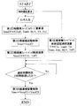
本実施態様では、メインコントローラ7により、たとえば図2、図3に示すような制御が行われる。
第1圧縮機構9は、固定容量式であり、クラッチ信号によりコントロールされ、クラッチ信号は、蒸発器温度目標値(Toff) と、蒸発器出口空気温度センサ16により検出された蒸発器出口空気温度(Teva)とから、次式によって演算される。
クラッチ信号=f(Toff, Teva)
そして、第2圧縮機構12が運転されているときは、蒸発器温度制御は、その容量制御手段により行われ、容量制御信号11により容量可変機構を制御するか、あるいは、第2圧縮機構12駆動用の電動モータの回転数制御により制御される。この第2圧縮機構12の制御方法の例を、図2、図3を参照しながら説明する。
In this embodiment, the main controller 7 performs control as shown in FIGS. 2 and 3, for example.
The first compression mechanism 9 is of a fixed capacity type and is controlled by a clutch signal. The clutch signal includes an evaporator temperature target value (Toff) and an evaporator outlet air temperature (detected by the evaporator outlet air temperature sensor 16). Teva) is calculated by the following equation.
Clutch signal = f (Toff, Teva)
When the
まず、第2圧縮機構蒸発器温度制御方法についてであるが、第2圧縮機構12は、フィードフォワード(FF)演算項、フィードバック(FB)演算項により、その圧縮容量が制御されるものである。但し、FF、FB演算項は運転状態に適合した、制御方法を持つものである。特に、第2圧縮機構単独運転時と比較して、第1及び第2圧縮機構による同時運転時との違いを持たせてある。ここでは、本システムにおける第2圧縮機構12の同時運転状態による制御方法を示す。
First, regarding the second compression mechanism evaporator temperature control method, the compression capacity of the
第1及び第2圧縮機構による同時運転時制御方法:
(1)第1圧縮機構9及び第2圧縮機構12により同時に運転されるとき、第2圧縮機構12のフィードフォワード演算項により、フィードフォワード容量演算値が出力され、その演算値を参照し、第2圧縮機構12の圧縮容量が制御される。但し、同時に運転されるときは、第2圧縮機構12のフィードフォワード演算項は、第2圧縮機構単独時のフィードフォワード演算項の演算方法を変更し、第1及び第2圧縮機構による同時運転に適合したフィードフォワード演算値を算出するものとする。つまり、第2圧縮機構12の圧縮容量の制御演算値(Nmo) としては、次式のようにフィードフォワード演算値(NmoFF) とフィードバック演算値(NmoFB) との合計値とされ、フィードフォワード演算値(NmoFF)はたとえば蒸発器温度目標値(Toff) 、外気温度(Tamb)、車速(VS)やエンジン回転数(Ne)、ブロワ(送風機)電圧(BLV) 等から次式のように算出される。
Nmo=NmoFF+NmoFB
NmoFF=A ×Toff + B×Tamb + C×VS + D×BLV
ここで、A 、B 、C 、D は定数である。
Control method during simultaneous operation by the first and second compression mechanisms:
(1) When simultaneously operated by the first compression mechanism 9 and the
Nmo = NmoFF + NmoFB
NmoFF = A × Toff + B × Tamb + C × VS + D × BLV
Here, A, B, C and D are constants.
同様に、フィードバック演算値を用いる場合にも、フィードバック演算値(NmoFB) は、第2圧縮機構単独運転時と、第1及び第2圧縮機構による同時運転時とは異なる演算値とされることが好ましく、これはとくに、フィードバック演算値(NmoFB) が次式のように演算される際、その比例ゲインKpを変更することにより行われる。つまり、第1及び第2圧縮機構により同時に運転されるとき、第2圧縮機構のフィードフォワード及びフィードバック演算項により制御されるが、第2圧縮機構のフィードバック演算項は、第2圧縮機構単独時のフィードバック演算項の演算に関わる係数(比例ゲイン等)を変更し、第1及び第2圧縮機構による同時運転に適したフィードバックとするものである。
NmoFB=NmoP(比例演算値)+ NmoI(積分演算値)
NmoP =Kp×(Teva-Toff)
NmoI =NmoIn-1 + Kp/Ti ×(Teva-Toff)
ここで、Kpは比例ゲイン、Tiは積分時間、NmoIn-1 はNmoIの前回演算値である。
Similarly, when the feedback calculation value is used, the feedback calculation value (NmoFB) may be a calculation value that is different from that when the second compression mechanism is operated independently and when the first and second compression mechanisms are operated simultaneously. This is preferably done by changing the proportional gain Kp when the feedback calculation value (NmoFB) is calculated as follows: In other words, when operated simultaneously by the first and second compression mechanisms, it is controlled by the feedforward and feedback calculation terms of the second compression mechanism, but the feedback calculation term of the second compression mechanism is the same as when the second compression mechanism alone. A coefficient (proportional gain or the like) related to the calculation of the feedback calculation term is changed to provide feedback suitable for simultaneous operation by the first and second compression mechanisms.
NmoFB = NmoP (proportional value) + NmoI (integral value)
NmoP = Kp × (Teva-Toff)
NmoI = NmoIn-1 + Kp / Ti × (Teva-Toff)
Here, Kp is a proportional gain, Ti is an integration time, and NmoIn-1 is a previously calculated value of NmoI.
また、第1圧縮機構9のみによる運転状態から第1及び第2圧縮機構により同時に運転されるとき、第2圧縮機構12のフィードフォワード演算値のみにより、第2圧縮機構12を起動し、容量を制御し、予め求めた所定時間(T)は、第2圧縮機構12のフィードバック演算項の出力を制限または演算停止させて、所定時間(T)経過後に前記フィードバック演算項の制限または演算停止解除し、フィードフォワード及びフィードバックによる制御とすることができる。このような制御のフローの例を図3に示す。すなわち、フィードフォワード制御によって起動し、フィードバック制御を所定時間制限または演算停止するものである。
Further, when the first and second compression mechanisms are operated simultaneously from the operation state of only the first compression mechanism 9, the
本発明に係る空調装置は、互いに独立した固定容量圧縮機構及び可変容量圧縮機構を備えた、あらゆる冷凍サイクルを好適に適用でき、とくに熱負荷変動の激しい建設機械のキャビン用空調装置に適用して最適なものである。 The air conditioner according to the present invention can be suitably applied to any refrigeration cycle having a fixed capacity compression mechanism and a variable capacity compression mechanism that are independent of each other. It is the best one.
1 空調装置
2 通風ダクト
3 外気または/および内気導入口
4 送風機
5 蒸発器
6 冷凍サイクル
7 メインコントローラ
8 駆動制御信号
9 第1圧縮機構
10 吐出容量信号
11 容量制御信号
12 第2圧縮機構
13 凝縮器
14 受液器
15 膨張弁
16 蒸発器出口空気温度センサ
17 車室内温度センサ
18 外気温度センサ
19 日射センサ
DESCRIPTION OF
Claims (8)
前記第2圧縮機構フィードフォワード圧縮容量演算手段が、前記第2圧縮機構による単独運転時と、前記第1圧縮機構及び第2圧縮機構の同時運転時とについて、互いに異なる第2圧縮機構フィードフォワード圧縮容量演算式により第2圧縮機構フィードフォワード圧縮容量を算出するとともに、前記第2圧縮機構フィードバック圧縮容量演算手段が、前記第2圧縮機構による単独運転時と、前記第1圧縮機構及び第2圧縮機構の同時運転時とについて、係数が互いに異なる第2圧縮機構フィードバック圧縮容量演算式により第2圧縮機構フィードバック圧縮容量を演算し、
前記圧縮機構運転切替制御手段により、第1圧縮機構による単独運転から、第1圧縮機構及び第2圧縮機構による同時運転に切替時、予め定めた所定時間内においては、前記第2圧縮機構フィードバック圧縮容量演算手段により演算された第2圧縮機構フィードバック圧縮容量を参照することなく前記第2圧縮機構フィードフォワード圧縮容量のみを参照し、前記第2圧縮機構容量制御手段により第2圧縮機構の容量を制御して同時運転に切り替えることを特徴とする空調装置。 A second compression mechanism having two compression mechanisms, a fixed capacity type first compression mechanism and a variable capacity type second compression mechanism, which are independent of each other, and controlling the capacity of the second compression mechanism, during the refrigeration cycle Capacity control means, compression mechanism operation switching control means for switching to operation by the two compression mechanisms, or operation by one of the compression mechanisms, a refrigerant evaporator for cooling the air-conditioning air, a refrigerant condenser, air to the evaporator A second compression mechanism feedforward compression capacity computing means for calculating a second compression mechanism feedforward compression capacity as a compression capacity for feedforward control in the second compression mechanism, an evaporator or an evaporator outlet air temperature Evaporator temperature detection means for detecting the target temperature of the evaporator or evaporator outlet air temperature, evaporator target temperature calculation means for calculating the target temperature of the evaporator outlet air temperature, evaporator or evaporator Second compression for computing the second compression mechanism feedback compression capacity as the compression capacity for the feedback control in the second compression mechanism by reference to the deviation between the target temperature of the mouth air temperature and the evaporator or evaporator outlet air temperature In an air conditioner equipped with mechanism feedback compression capacity calculation means,
The second compression mechanism feedforward compression capacity calculation means is different in second compression mechanism feedforward compression during independent operation by the second compression mechanism and during simultaneous operation of the first compression mechanism and the second compression mechanism. The second compression mechanism feedforward compression capacity is calculated by a capacity calculation formula, and the second compression mechanism feedback compression capacity calculation means is operated in the single operation by the second compression mechanism, and the first compression mechanism and the second compression mechanism. And calculating the second compression mechanism feedback compression capacity using the second compression mechanism feedback compression capacity calculation formulas having different coefficients .
When the compression mechanism operation switching control means switches from the single operation by the first compression mechanism to the simultaneous operation by the first compression mechanism and the second compression mechanism, the second compression mechanism feedback compression is performed within a predetermined time. Only the second compression mechanism feedforward compression capacity is referred to without referring to the second compression mechanism feedback compression capacity calculated by the capacity calculation means, and the capacity of the second compression mechanism is controlled by the second compression mechanism capacity control means. And switching to simultaneous operation .
前記第2圧縮機構フィードフォワード圧縮容量演算手段が、前記第2圧縮機構による単独運転時と、前記第1圧縮機構及び第2圧縮機構の同時運転時とについて、互いに異なる第2圧縮機構フィードフォワード圧縮容量演算式により第2圧縮機構フィードフォワード圧縮容量を算出し、第2圧縮機構単独運転時には冷凍サイクル熱負荷を参照することにより、第1及び第2圧縮機構同時運転時には冷凍サイクル熱負荷及び、第1圧縮機構の駆動源である原動機の回転数または/及び該原動機により走行される車の速度を参照することにより、第2圧縮機構フィードフォワード圧縮容量を算出することを特徴とする空調装置。 A second compression mechanism having two compression mechanisms, a fixed capacity type first compression mechanism and a variable capacity type second compression mechanism, which are independent of each other, and controlling the capacity of the second compression mechanism, during the refrigeration cycle Capacity control means, compression mechanism operation switching control means for switching to operation by the two compression mechanisms, or operation by one of the compression mechanisms, a refrigerant evaporator for cooling the air-conditioning air, a refrigerant condenser, air to the evaporator In an air conditioner comprising a second compression mechanism feedforward compression capacity calculating means for calculating a second compression mechanism feedforward compression capacity as a compression capacity for feedforward control in the second compression mechanism,
The second compression mechanism feedforward compression capacity calculation means is different in second compression mechanism feedforward compression during independent operation by the second compression mechanism and during simultaneous operation of the first compression mechanism and the second compression mechanism. By calculating the feedforward compression capacity of the second compression mechanism using the capacity calculation formula, and referring to the refrigeration cycle thermal load during the second operation of the second compression mechanism, the refrigeration cycle heat load during the simultaneous operation of the first and second compression mechanisms, An air conditioner that calculates a feed-forward compression capacity of a second compression mechanism by referring to a rotational speed of a prime mover that is a driving source of one compression mechanism and / or a speed of a vehicle that is driven by the prime mover .
前記第2圧縮機構フィードフォワード圧縮容量演算手段が、前記第2圧縮機構による単独運転時と、前記第1圧縮機構及び第2圧縮機構の同時運転時とについて、互いに異なる第2圧縮機構フィードフォワード圧縮容量演算式により第2圧縮機構フィードフォワード圧縮容量を算出するとともに、前記第2圧縮機構フィードバック圧縮容量演算手段が、前記第2圧縮機構による単独運転時と、前記第1圧縮機構及び第2圧縮機構の同時運転時とについて、係数が互いに異なる第2圧縮機構フィードバック圧縮容量演算式により第2圧縮機構フィードバック圧縮容量を演算し、第2圧縮機構単独運転時には冷凍サイクル熱負荷を参照することにより、第1及び第2圧縮機構同時運転時には冷凍サイクル熱負荷及び、第1圧縮機構の駆動源である原動機の回転数または/及び該原動機により走行される車の速度を参照することにより、第2圧縮機構フィードフォワード圧縮容量を算出することを特徴とする空調装置。 A second compression mechanism having two compression mechanisms, a fixed capacity type first compression mechanism and a variable capacity type second compression mechanism, which are independent of each other, and controlling the capacity of the second compression mechanism, during the refrigeration cycle Capacity control means, compression mechanism operation switching control means for switching to operation by the two compression mechanisms, or operation by one of the compression mechanisms, a refrigerant evaporator for cooling the air-conditioning air, a refrigerant condenser, air to the evaporator blower for blowing, second compression mechanism feedforward compression capacity calculation means for calculating a second compression mechanism feedforward compression capacity as the compression capacity for the feed-forward control of the second compression mechanism, an evaporator or evaporator outlet air temperature Evaporator temperature detection means for detecting the target temperature of the evaporator or evaporator outlet air temperature, evaporator target temperature calculation means for calculating the target temperature of the evaporator outlet air temperature, evaporator or evaporator Second compression for computing the second compression mechanism feedback compression capacity as the compression capacity for the feedback control in the second compression mechanism by reference to the deviation between the target temperature of the mouth air temperature and the evaporator or evaporator outlet air temperature In an air conditioner equipped with mechanism feedback compression capacity calculation means,
The second compression mechanism feedforward compression capacity calculation means is different in second compression mechanism feedforward compression during independent operation by the second compression mechanism and during simultaneous operation of the first compression mechanism and the second compression mechanism. The second compression mechanism feedforward compression capacity is calculated by a capacity calculation formula, and the second compression mechanism feedback compression capacity calculation means is operated in the single operation by the second compression mechanism, and the first compression mechanism and the second compression mechanism. for a time of simultaneous operation, coefficients calculates the second compression mechanism feedback compression volume by different second compression mechanism feedback compression capacity calculation formula, by the second compression mechanism alone during operation Referring to the refrigeration cycle heat load, the The refrigeration cycle heat load and the drive source of the first compression mechanism during simultaneous operation of the first and second compression mechanisms By referring to the speed of the car is traveling by the rotational speed and / or prime mover motive, air-conditioning system and calculates the second compression mechanism feedforward compression capacity.
Priority Applications (4)
| Application Number | Priority Date | Filing Date | Title |
|---|---|---|---|
| JP2004038595A JP4436152B2 (en) | 2004-02-16 | 2004-02-16 | Air conditioner |
| PCT/JP2005/001663 WO2005077689A1 (en) | 2004-02-16 | 2005-02-04 | Air conditioner |
| EP05709729A EP1717075A4 (en) | 2004-02-16 | 2005-02-04 | Air conditioner |
| US10/598,034 US20080223058A1 (en) | 2004-02-16 | 2005-02-04 | Air Conditioner |
Applications Claiming Priority (1)
| Application Number | Priority Date | Filing Date | Title |
|---|---|---|---|
| JP2004038595A JP4436152B2 (en) | 2004-02-16 | 2004-02-16 | Air conditioner |
Publications (2)
| Publication Number | Publication Date |
|---|---|
| JP2005225439A JP2005225439A (en) | 2005-08-25 |
| JP4436152B2 true JP4436152B2 (en) | 2010-03-24 |
Family
ID=34857812
Family Applications (1)
| Application Number | Title | Priority Date | Filing Date |
|---|---|---|---|
| JP2004038595A Expired - Fee Related JP4436152B2 (en) | 2004-02-16 | 2004-02-16 | Air conditioner |
Country Status (4)
| Country | Link |
|---|---|
| US (1) | US20080223058A1 (en) |
| EP (1) | EP1717075A4 (en) |
| JP (1) | JP4436152B2 (en) |
| WO (1) | WO2005077689A1 (en) |
Families Citing this family (4)
| Publication number | Priority date | Publication date | Assignee | Title |
|---|---|---|---|---|
| JP4861900B2 (en) | 2007-02-09 | 2012-01-25 | サンデン株式会社 | Capacity control system for variable capacity compressor |
| US10145589B2 (en) * | 2013-03-15 | 2018-12-04 | Whirlpool Corporation | Net heat load compensation control method and appliance for temperature stability |
| US9989286B2 (en) | 2013-12-17 | 2018-06-05 | Lennox Industries Inc. | Compressor operation management in air conditioners |
| GB2547806B (en) * | 2017-02-28 | 2018-02-28 | Cotopaxi Ltd | System and method for controlling compressor operating capacity of a refrigeration plant |
Family Cites Families (10)
| Publication number | Priority date | Publication date | Assignee | Title |
|---|---|---|---|---|
| JP2508043B2 (en) * | 1987-01-12 | 1996-06-19 | ダイキン工業株式会社 | Compressor capacity control device for refrigeration equipment |
| JPH03137457A (en) * | 1989-10-20 | 1991-06-12 | Daikin Ind Ltd | Freezer device |
| JP2969388B2 (en) * | 1991-04-30 | 1999-11-02 | 松下冷機株式会社 | Multi-room air conditioner |
| JP3492849B2 (en) * | 1996-05-01 | 2004-02-03 | サンデン株式会社 | Vehicle air conditioner |
| JP2001090667A (en) * | 1999-09-21 | 2001-04-03 | Toyota Autom Loom Works Ltd | Control device for variable displacement compressor |
| JP4186361B2 (en) * | 1999-12-22 | 2008-11-26 | 株式会社デンソー | Air conditioner for vehicles |
| JP4613455B2 (en) | 2001-07-06 | 2011-01-19 | 株式会社デンソー | Vehicle cooling system |
| JP3936199B2 (en) * | 2002-01-23 | 2007-06-27 | サンデン株式会社 | Air conditioner for vehicles |
| US6761037B2 (en) * | 2002-01-23 | 2004-07-13 | Sanden Corporation | Vehicle air conditioner using a hybrid compressor |
| KR100487149B1 (en) * | 2002-06-14 | 2005-05-03 | 삼성전자주식회사 | Air conditioning apparatus and control method thereof |
-
2004
- 2004-02-16 JP JP2004038595A patent/JP4436152B2/en not_active Expired - Fee Related
-
2005
- 2005-02-04 WO PCT/JP2005/001663 patent/WO2005077689A1/en not_active Application Discontinuation
- 2005-02-04 EP EP05709729A patent/EP1717075A4/en not_active Withdrawn
- 2005-02-04 US US10/598,034 patent/US20080223058A1/en not_active Abandoned
Also Published As
| Publication number | Publication date |
|---|---|
| EP1717075A1 (en) | 2006-11-02 |
| EP1717075A4 (en) | 2008-05-21 |
| US20080223058A1 (en) | 2008-09-18 |
| WO2005077689A1 (en) | 2005-08-25 |
| JP2005225439A (en) | 2005-08-25 |
Similar Documents
| Publication | Publication Date | Title |
|---|---|---|
| JP2004299667A (en) | Air-conditioner for vehicle | |
| JP2005009794A (en) | Freezing cycle control device | |
| JPH1123081A (en) | Air conditioner having cooler for heat generating instrument | |
| JP2005193749A (en) | Controller | |
| JP2007106260A (en) | Air conditioner for vehicle | |
| EP1717527B1 (en) | Air conditioner | |
| JP4436152B2 (en) | Air conditioner | |
| US20070130975A1 (en) | Air conditioning system for vehicles | |
| JP5118441B2 (en) | Air conditioner for vehicles | |
| JP2003312474A (en) | Method of controlling dehumidification in air-conditioner for rolling stock, and rolling stock air-conditioner | |
| WO2017014030A1 (en) | Air-conditioning apparatus for vehicles | |
| WO2005077688A1 (en) | Air conditioner | |
| JP3936199B2 (en) | Air conditioner for vehicles | |
| JP2012076589A (en) | Air conditioner for vehicle | |
| JP4482503B2 (en) | Control device | |
| JP5195378B2 (en) | Air conditioning control device for vehicles | |
| JP4285228B2 (en) | Air conditioner for vehicles | |
| JP2007320392A (en) | Refrigerating cycle device | |
| JP2010047149A (en) | Vehicular air conditioner | |
| JP2003291633A (en) | Air conditioner for vehicle | |
| JP3947672B2 (en) | Air conditioner for vehicles | |
| JP2008002795A (en) | Refrigeration cycle system | |
| JP2006088956A (en) | Control device | |
| JP2004232995A (en) | Refrigeration cycle device | |
| JP2009174775A (en) | Refrigeration system |
Legal Events
| Date | Code | Title | Description |
|---|---|---|---|
| A621 | Written request for application examination |
Free format text: JAPANESE INTERMEDIATE CODE: A621 Effective date: 20060720 |
|
| A131 | Notification of reasons for refusal |
Free format text: JAPANESE INTERMEDIATE CODE: A131 Effective date: 20090807 |
|
| A521 | Written amendment |
Free format text: JAPANESE INTERMEDIATE CODE: A523 Effective date: 20090901 |
|
| TRDD | Decision of grant or rejection written | ||
| A01 | Written decision to grant a patent or to grant a registration (utility model) |
Free format text: JAPANESE INTERMEDIATE CODE: A01 Effective date: 20091120 |
|
| A01 | Written decision to grant a patent or to grant a registration (utility model) |
Free format text: JAPANESE INTERMEDIATE CODE: A01 |
|
| A61 | First payment of annual fees (during grant procedure) |
Free format text: JAPANESE INTERMEDIATE CODE: A61 Effective date: 20091225 |
|
| R150 | Certificate of patent or registration of utility model |
Free format text: JAPANESE INTERMEDIATE CODE: R150 |
|
| FPAY | Renewal fee payment (event date is renewal date of database) |
Free format text: PAYMENT UNTIL: 20130108 Year of fee payment: 3 |
|
| FPAY | Renewal fee payment (event date is renewal date of database) |
Free format text: PAYMENT UNTIL: 20130108 Year of fee payment: 3 |
|
| FPAY | Renewal fee payment (event date is renewal date of database) |
Free format text: PAYMENT UNTIL: 20140108 Year of fee payment: 4 |
|
| R250 | Receipt of annual fees |
Free format text: JAPANESE INTERMEDIATE CODE: R250 |
|
| R250 | Receipt of annual fees |
Free format text: JAPANESE INTERMEDIATE CODE: R250 |
|
| S533 | Written request for registration of change of name |
Free format text: JAPANESE INTERMEDIATE CODE: R313533 |
|
| R350 | Written notification of registration of transfer |
Free format text: JAPANESE INTERMEDIATE CODE: R350 |
|
| R250 | Receipt of annual fees |
Free format text: JAPANESE INTERMEDIATE CODE: R250 |
|
| R250 | Receipt of annual fees |
Free format text: JAPANESE INTERMEDIATE CODE: R250 |
|
| LAPS | Cancellation because of no payment of annual fees |