JP4435172B2 - Equipment for filling and / or discharging containers filled with and / or to be filled and operating devices for transporting the containers - Google Patents
Equipment for filling and / or discharging containers filled with and / or to be filled and operating devices for transporting the containers Download PDFInfo
- Publication number
- JP4435172B2 JP4435172B2 JP2006540223A JP2006540223A JP4435172B2 JP 4435172 B2 JP4435172 B2 JP 4435172B2 JP 2006540223 A JP2006540223 A JP 2006540223A JP 2006540223 A JP2006540223 A JP 2006540223A JP 4435172 B2 JP4435172 B2 JP 4435172B2
- Authority
- JP
- Japan
- Prior art keywords
- container
- operating device
- filled
- containers
- gripping
- Prior art date
- Legal status (The legal status is an assumption and is not a legal conclusion. Google has not performed a legal analysis and makes no representation as to the accuracy of the status listed.)
- Expired - Fee Related
Links
Images


Classifications
-
- B—PERFORMING OPERATIONS; TRANSPORTING
- B65—CONVEYING; PACKING; STORING; HANDLING THIN OR FILAMENTARY MATERIAL
- B65G—TRANSPORT OR STORAGE DEVICES, e.g. CONVEYORS FOR LOADING OR TIPPING, SHOP CONVEYOR SYSTEMS OR PNEUMATIC TUBE CONVEYORS
- B65G47/00—Article or material-handling devices associated with conveyors; Methods employing such devices
- B65G47/74—Feeding, transfer, or discharging devices of particular kinds or types
- B65G47/90—Devices for picking-up and depositing articles or materials
- B65G47/91—Devices for picking-up and depositing articles or materials incorporating pneumatic, e.g. suction, grippers
- B65G47/914—Devices for picking-up and depositing articles or materials incorporating pneumatic, e.g. suction, grippers provided with drive systems incorporating rotary and rectilinear movements
-
- A—HUMAN NECESSITIES
- A24—TOBACCO; CIGARS; CIGARETTES; SIMULATED SMOKING DEVICES; SMOKERS' REQUISITES
- A24C—MACHINES FOR MAKING CIGARS OR CIGARETTES
- A24C5/00—Making cigarettes; Making tipping materials for, or attaching filters or mouthpieces to, cigars or cigarettes
- A24C5/35—Adaptations of conveying apparatus for transporting cigarettes from making machine to packaging machine
- A24C5/352—Adaptations of conveying apparatus for transporting cigarettes from making machine to packaging machine using containers, i.e. boats
Abstract
Description
本発明は、充填された及び/又は充填すべき容器を、貯蔵部と容器の充填状態を変更する装置間で搬送するための少なくとも1つの操作装置と、容器の充填状態を変更する少なくとも1つの装置と、充填された及び/又は充填すべき容器を収容するための少なくとも1つの貯蔵部とを有する、物品で充填された及び/又は充填すべき容器の充填及び/又は排出をするための設備に関する。更に、本発明は、複数の自由度で可動に形成されている操作アームと、操作アームの自由端に可動に配設されており、その上に可動の担持要素を有する少なくとも1つの直動ガイドと容器用の保持要素とを備える把持要素と、担持要素を運動させるための駆動機構とを有する、前記設備の構成要素としての操作装置に関する。 The present invention, the filled and / or containers to be filled, and at least one operating device for transporting between devices for changing the state of filling the reservoir and the container, at least one of changing the state of filling containers Equipment for filling and / or discharging containers filled with and / or to be filled with an article and having at least one reservoir for containing filled and / or containers to be filled About. Furthermore, the present invention provides at least one linear motion guide having an operation arm that is movable with a plurality of degrees of freedom and a movable end disposed on the free end of the operation arm. The present invention relates to an operating device as a component of the equipment, having a gripping element including a container holding element and a drive mechanism for moving a carrier element.
このような設備と操作装置は、特にタバコ加工産業において使用される。しばしば、物品は、異なった理由から加工部から導出され、後の時点で再び加工部に導入されなければならない。例えば、タバコスティック等と結合する前にフィルタを硬化する必要がある。他の例では、シガレットの供給過剰分は、中間貯蔵されなければならない。フィルタ、シガレット、又は他の物品は、このため充填ステーションにおいて容器に、いわゆるトレイに、充填され、操作装置によって蓄積部に搬入される。トレイに留保された物品を再び加工部に導入する場合のために、トレイは、貯蔵部から取り出され、排出ステーションに供給されなければならない。 Such equipment and operating devices are used in particular in the tobacco processing industry. Often, the article must be derived from the processing section for different reasons and reintroduced into the processing section at a later point in time. For example, the filter needs to be cured before being joined to a tobacco stick or the like. In another example, the excess supply of cigarette must be stored intermediately. Filters, cigarettes or other articles are thus filled in containers, so-called trays, at the filling station and carried into the storage by the operating device. In order for the articles retained in the tray to be reintroduced into the processing section, the tray must be removed from the storage section and fed to the discharge station.
公知の設備の場合、貯蔵部は、容器の充填状態を変更する装置の領域に配設されており、操作装置が運転中でも操作可能であるように、設備は開放して形成されている。貯蔵部と容器の充填状態を変更するための装置は、また、広範な搬送経路を有する操作装置の複雑な運動経過が必要であるようにも配設されている。容器を搬送するための公知の操作装置は、それぞれ特別に適合された容器のために使用可能である。 In the case of a known facility, the storage part is arranged in the region of the device for changing the filling state of the container, and the facility is formed open so that the operation device can be operated even during operation. The device for changing the filling state of the reservoir and the container is also arranged in such a way that a complicated course of movement of the operating device with a wide transport path is required. Known operating devices for transporting containers can be used for each specially adapted container.
公知の設備は、貯蔵部から容器の充填状態を変更する装置に及びその逆に容器を搬送するための膨大な移動経路のために、出力を、即ち特に搬送すべき物品の装入量を、低減することが必要であるという欠点を備える。更に、開放した設備は、操作員のための安全に対して著しいリスクを秘めている。容器を搬送するための公知の操作装置は、異なった容器の形態及び寸法に適応させることができるように、限定的にしか使用可能でないか、構造的に非常に費用がかかるという欠点を備える。 The known equipment provides output, i.e. in particular the load of the article to be transported, for the enormous movement path for transporting the container from the reservoir to the device for changing the filling state of the container, and vice versa. It has the disadvantage that it needs to be reduced. Furthermore, open equipment carries significant risks to safety for operators. Known operating devices for transporting containers have the disadvantage that they can only be used in a limited way or can be very expensive in construction so that they can be adapted to different container configurations and dimensions.
従って、本発明の課題は、容易に操作可能で安全である、コンパクトで自在に使用可能な設備を提供することにある。更に、本発明の課題は、容易に操作可能で自在に使用可能な操作装置を提供することにある。 Accordingly, an object of the present invention is to provide a compact and freely usable facility that can be easily operated and is safe. Furthermore, the subject of this invention is providing the operating device which can be operated easily and can be used freely.
この課題は、一方で、冒頭で述べた様式の設備によれば、操作装置が、容器の充填状態を変更する少なくとも1つの装置と少なくとも1つの貯蔵部とをフェンス要素によって互いに結合することにより構成される作業空間もしくはセル内に配設されており、これにより、設備が、閉じたユニットとして形成されていること、各貯蔵部が、その内方に向いた操作装置に面した側を閉鎖可能であるように、選択的に開閉可能なスルース要素を介してフェンス要素に結合されており、貯蔵部が、スルース要素に連結可能又はスルース要素から連結解除可能であり、これにより、貯蔵部が、設備の運転中に交換可能であることによって解決される。閉じたセルを構成することにより、非常に短い搬送経路による容器の搬送を保証する、非常にコンパクトで、同時に安全な設備が提供される。これにより、容器の交換時間が低減される。 This problem is achieved, on the other hand, by the operating device according to the facility of the style described at the beginning by connecting at least one device for changing the filling state of the container and at least one reservoir to each other by means of a fence element. It is arranged in a working space or cell , so that the equipment is formed as a closed unit , each storage can be closed on the side facing the operating device facing inward Is coupled to the fence element via a sluice element that can be selectively opened and closed, and the reservoir is connectable to or detachable from the sluice element, whereby the reservoir is It is solved by being replaceable during operation of the equipment . Constructing a closed cell provides a very compact and at the same time safe installation that guarantees the transport of the container over a very short transport path. Thereby, the replacement time of the container is reduced.
有利なことに、貯蔵部は、その内方に向いた操作装置に面した側を閉鎖可能であり、これは、各貯蔵部が、選択的に開放又は閉鎖すべきスルース要素に付設されていることによって得られる。この形成により、設備の運転中の貯蔵部の交換が保証される。従って、貯蔵部は、本来のセルから連結解除もしくは分離されているので、操作装置の不作為の介入が排除されている。 Advantageously, the reservoirs can be closed on the side facing the inwardly facing operating device, each reservoir being attached to a sluice element to be selectively opened or closed Can be obtained. This formation ensures replacement of the storage part during operation of the equipment. Thus, since the reservoir is disconnected or separated from the original cell, random intervention of the operating device is eliminated.
好ましくは、容器の、開放された貯蔵部から出て行く方向に向いた側の平滑な部分面を把持可能であるように、操作装置が自在に形成されている。これは、柔軟で本質的に容器の形態及び形状によって拘束されない設備の使用を可能にする。 Preferably, the operating device is freely formed so as to be able to grip a smooth partial surface on the side facing the direction going out of the open storage part of the container. This allows the use of equipment that is flexible and essentially unconstrained by the form and shape of the container.
更に、本発明の課題は、冒頭で述べた様式の特徴を有する操作装置によれば、容器の、貯蔵部から出て行く方向に向いた側の平滑な部分面を把持可能であるように、把持要素が形成されていること、担持要素に、容器の底を支持する支持要素が配設されていることによって解決される。これにより、操作装置の柔軟な使用が保証され、しかも本質的に普通の容器の形状及び形態に依存しない。 Furthermore, the problem of the present invention is that according to the operating device having the characteristics of the style described at the beginning, it is possible to grip a smooth partial surface of the container facing the direction going out of the storage section. This is solved by the fact that the gripping element is formed and the support element is provided with a support element for supporting the bottom of the container . This ensures a flexible use of the operating device and is essentially independent of the usual container shape and form.
好ましくは、把持要素は、容器に面した側に、容器を押す及び/又は移動させるための要素を備える。これにより、付加的な把持及び又は固定要素を省略することができるので、操作装置の構造は簡素化される。この形成も、特に簡単に自在な使用を可能にする。 Preferably, the gripping element comprises an element for pushing and / or moving the container on the side facing the container. Thereby, an additional gripping and / or fixing element can be omitted, so that the structure of the operating device is simplified. This formation also allows a particularly simple and free use.
本発明の好ましい実施形態では、把持要素が、特に容器を引くための少なくとも1つの、好ましくは2つの、吸引カップと、特に容器を押すための少なくとも1つの、好ましくは2つの、バッファ要素を備える。吸引カップとバッファ要素によって、容器は、搬送のために最低の要求しか、即ち普通の各容器が備える小さい作用面しか満足する必要がないので、全ての普通の容器形態が、操作装置によって搬送可能であり、しかも付加的な構造的な消費がない。 In a preferred embodiment of the invention, the gripping element comprises at least one, preferably two, suction cups, in particular for pulling the container, and at least one, preferably two, buffer elements, in particular for pushing the container. . With suction cups and buffer elements, containers can be transported by the operating device since the containers need to satisfy the minimum requirements for transport, i.e. only the small working surfaces of each ordinary container. And there is no additional structural consumption.
本発明の更に有利で好ましい特徴及び実施形態は、下位の請求項及び後続の説明から分かる。特に好ましい実施形態を、添付図を基にして詳細に説明する。 Further advantageous and preferred features and embodiments of the invention can be seen from the subclaims and the subsequent description. Particularly preferred embodiments will be described in detail with reference to the accompanying drawings.
図に示した設備は、物品で充填された又は充填すべき容器の排出、充填及び貯蔵をするために使用される。自在の把持システムとしての操作装置は、設備の構成要素であり、設備の個々の構成要素間で容器を搬送するために使用される。 The equipment shown in the figure is used for evacuating, filling and storing containers filled with or to be filled with articles. The operating device as a free gripping system is a component of the equipment and is used to transport containers between the individual components of the equipment.
図1には、このような設備10が示されており、この設備は、本質的に中央の操作装置11と、容器13の排出をするための装置12と、容器13の充填をするための装置14と、4つの貯蔵部15,16,17,18とから構成されており、この場合、装置12及び13と貯蔵部15〜16とは、作業空間20を構成するためのフェンス要素19によって互いに結合されている。操作装置11は、作業空間20内に配設されており、これにより外方に対して遮蔽されている。作業空間20は、いわば閉じたセルを構成し、このセル内で、操作装置11は、複数の自由度で、移動可能、旋回可能、又は他の方式で運動可能である。選択的に、容器13の充填状態を変更する、容器13の排出もしくは充填をするための装置12及び14の数と貯蔵部15〜18の数は変えることができる。
FIG. 1 shows such an installation 10, which essentially comprises a central operating device 11, a
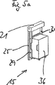
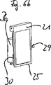
貯蔵部15〜18は、その内方に向いた操作装置11もしくは作業空間20に面した側を閉鎖可能に形成されている。このため、各貯蔵部15〜18には、スルース要素が付設されており、このスルース要素は、例えばロールアップゲート21,22,23,24として形成することができる。ロールアップゲート21〜24は、貯蔵部15〜18をそれぞれ作業空間20から連結解除するために、開放し、再び閉鎖することができる。図1では、ロールアップゲート21は開放されており、一方、ロールアップゲート22〜24は閉鎖されている。貯蔵部15〜18は、貯蔵部15〜18を場合によっては交換することができるように、スルース要素もしくはロールアップゲート21〜24に連結可能で、再び連結解除可能である。貯蔵部15〜18は、特に設備10の運転中に確実な位置決めを保証することができるように、ロールアップゲート21〜24のフレーム25,26,27,28に固定可能である。固定は、フレーム25〜28の横に配設されたプレート要素29,30(例えば図5a及び5b参照)によって実現される。プレート要素29,30は、旋回可能に形成され、ロールアップゲート21〜24の開口部に対して接線方向の固定も、プレート要素29,30が外方へと旋回されている場合には垂直な固定も可能にする。
The
装置12及び14は、相並んで配設されている。容器13の排出をするための装置12の前には、上のベルトステーション31と下のベルトステーション32とが接続されている。ベルトステーション31は、満杯の容器13を取り外し、これを装置12に供給するために使用される。ベルトステーション32は、装置12内で空になった容器13を取り外し、これを装置12から導き出すために使用される。容器13の充填をするための装置14は、同様に上のベルトステーション33と下のベルトステーション34を備えており、この場合、ベルトステーション33は、空の容器13を取り出し、これを装置14に供給するために使用され、ベルトステーション34は、装置14内で充填された容器13を取り外し、これを装置14から導き出すために使用される。ベルトステーション31〜34は、全てが、同じ方向に、しかも容器13がその長手方向への広がりに対して横に、即ち幅広側を前にして移送可能であるように整向されている。
各装置12及び14には、示した実施形態では、2つの貯蔵部15,16と17,18が付設されている。貯蔵部15及び18は、90°だけずらして装置12もしくは14に付設されている。これは、貯蔵部15及び18内の容器13の向きがベルトステーション31〜34と同じであることを意味する。貯蔵部16もしくは17は、貯蔵部15及び18に対して90°だけずらして配設されており、操作装置11の装置12,14と向かい合っている側に存在する。装置12及び14は、それぞれ、上から容器13を操作するいわゆる「トップローダ」として形成するか、前もしくは横から容器13を操作する「フロントローダ」として形成することができる。
Each
貯蔵部15〜18は、選択的に固定式又は可動式に形成されている。固定式の貯蔵部としては、例えば容器13を収容するための隔室35を備える不動のフレームが問題となる。図示されてない他の実施形態では、位置不動のコンテナが、書架型収容部内に配設されており、例えば、操作装置11の把持領域に容器3を用意するためのベルトステーションを備えていてもよい。図5〜10には、異なった可動式の貯蔵部15〜18が示されている。図5aは、トレイトロリとも呼ばれるトロリ36を示す。トロリ36は、フレーム25の領域にあるロールアップゲート21に連結され、プレート要素29,30によって固定されている。ロールアップゲート21は開放されている(図5b参照)。ロールアップゲート21の閉鎖位置は、図6aから分かる。図6では、トロリ36がロールアップゲート21から連結解除されている。ロールアップゲート21は、異なった状態で、即ち、一方では図6による完全に閉鎖された位置に、存在することができる。この位置で、トロリ36を導き出しても、新しいトロリ36を連結してもよい。他方で、ロールアップゲート21は、その下縁部をトロリ36に上にいわば同一平面上に位置させることができるので(図5b参照)、トロリ36を取り出すことができる。(図示されてない)別の位置では、ロールアップゲート21の下縁部が、最大に上方へと移動される。この位置は、セルもしくは作業空間20に入ることができるように、設備10の運転を中断させるために設けられている。
The
トロリ36(例えば図7による)は、それぞれ7つの隔室35が配設されている3つの面37,38,39を備える。隔室35は、部分的に開放された容器13から物品が落ちることを防止するために、若干傾けた底要素40を備えている。更に、隔室35は、隔室35内に配設された容器13が、底側を、即ち底要素40に面した側を、操作装置11に対して操作可能であるように形成されている。
The trolley 36 (for example according to FIG. 7 ) comprises three
図8は、示された実施形態では3つのコンテナ42を備えるコンテナトロリ41を示す。コンテナ42は、不動又は可動にコンテナトロリ41に配設することができる。コンテナ42の隔室35は、隔室35内に配設された容器13が底側を操作装置11に対して操作不能であり、容器13の支持が容器を部分的に引き出した後に初めて可能であるように形成されている。
FIG. 8 shows a
貯蔵部15〜18の別の実施形態は、図9及び10に図示されている。ここに示された貯蔵部は、容器フレーム43としてトロリ36と同様に構成されているが、ローラの代わりに竹馬状の足44が設けられていることが異なっている。足44は、例えばドライバもしくはガイドのない搬送システム45が、容器フレームを交換するために、容器フレーム43の下に移動可能であるような高さに形成されている。図9a及び10aからは、更に、隔室35のそれぞれに、傾斜した底要素40に対応するようにガイドレール46が付設されていることを読み取ることができる。
Another embodiment of reservoirs 15-18 is illustrated in FIGS. The storage unit shown here is configured in the same manner as the
操作装置11は、容器13の、開放された貯蔵部15〜18から出て行く方向に向いた側の平滑な部分面を把持可能であるように、自在に形成されている。通常、各容器13は、貯蔵部15〜18とは逆に面した端面に、把持要素を作用させることができる少なくとも1つの小さな作用面を備える。以下で、設備10の構成要素としての操作装置11を詳細に説明する。
The operating device 11,
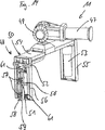
操作装置11は、本質的に操作アーム47と把持要素48とを備える。操作アーム47は、通常の方式で形成され、複数の自由度で運動可能であり、しかも直線方向に運動可能でもあり、旋回可能でもある。把持要素48は、操作アーム47の自由端49に運動可能に配設されている。把持要素48自身は、本質的にフレーム状の直動ガイド50と、可動の担持要素51と、容器13用の保持要素52とから成る。更に、把持要素48は、把持要素48に直線及び旋回運動をさせるための駆動機構53を備える。
The operating device 11 essentially comprises an
直動ガイド50は、ほぼU字形の形状を備える。このため、走行レール54が、対置する端部に、走行レール54から出て下方へと延在する2つのフレーム要素55及び56を備える。担持要素51は、容器13を把持したり、貯蔵部15〜18から出したり、貯蔵部15〜18に入れたりするために走行レール54上を移動可能である。把持要素48は、容器13の、貯蔵部15〜18から出て行く方向に向いた側の平滑な部分面を把持可能であるように形成されている。このため、把持要素48には、容器13を押す及び/又は引くための要素が配設されている。容器13を引くための要素は、吸引カップ57として形成されている。好ましくは2つの吸引カップ57は、担持要素51に互いに間隔を置いて上下に、しかも容器13に面した側に配設されている。各吸引カップ57には、容器13を押すためのバッファ要素58が付設されており、従って、2つのバッファ要素58は、担持要素51に互いに間隔を置いて上下に配設されている(例えば図15参照)。吸引カップ57は、図示されてない吸気ラインに接続されている。バッファ要素58は、弾性材料からほぼ高剛性に形成されている。
The
担持要素51には、容器13の底を支持する支持要素59が配設されている。図15では、支持要素59が、例えば固定式に形成されており、担持要素51から、吸引カップ57及びバッファ要素58と同じ方向に突出する。しかしながらまた、支持要素59は、運動可能もしくは待避可能に形成することができる(例えば図12b参照)。運動可能な支持要素59は、バネ負荷を受けており、待避位置ではバネ荷重に抗して吸引カップ57及びバッファ要素58の後に引戻されている(図12b)。支持位置(例えば図13b参照)では、支持要素59は、容器13の底60の下に位置決めされている。
A
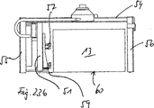
把持要素48には、好ましくは容器13に面した側の担持要素51の領域には、少なくとも1つのセンサ要素61が配設されている。好ましくは、複数の、特に3つのセンサ要素61が設けられている。センサ要素61は、特に容器の底の面並びに容器の後壁の面の位置を検知するために使用される。更に、把持要素48は、少なくとも1つの監視手段、好ましくはカメラ62が配設されている。カメラ62は、保持要素52に、しかも内容並びに内容の状態の観察をする目的のために容器13内の視察が保証されるように、配設されている(例えば図16参照)。
The gripping
図16から、更に、保持要素52が、加圧シリンダ64によって運動可能である押付けプレート63を有することが分かる。押付けプレート63は、容器13をその搬送時に固定するために使用される。容器13は、搬送の際に押付けプレート63とウェブ65間に挟まれ、この場合、容器13は、付加的にウェブ65と向かい合っている側で支持要素59上に支持される。押付けプレート63は、同様に加圧シリンダ64によって操作可能である別のプレート66と作用結合している。このプレート66は、容器13内に物品を固定するために使用される。
From Figure 16, further retaining
図19による別の実施形態では、容器13内の物品の望ましくない運動を検出し、光学的な品質コントロールをするために使用される複数のカメラ67が配設されている。このため、カメラ67は、搬送すべき容器13の上に配設されているので、視察を上から行なうことができる。
In another embodiment according to FIG. 19, a plurality of cameras 67 are provided which are used to detect unwanted movement of articles in the
本質的な処理の原理、特に貯蔵部15〜18から容器13を取り出すための工程を以下で説明する:
貯蔵部15〜18としてコンテナトロリ41を使用する場合、把持要素48は、例えば満杯の容器13をコンテナ42の1つの隔室35から取り出すために、この隔室35の前に位置決めされる。吸引カップ57は、隔室35内に入る。この場合、支持要素59は、バネ荷重に抗して押し戻されるので、支持要素は、入った状態では支持要素59ではなくストッパとして作用する。即ち、把持要素48は、隔室35の底要素40と衝突することなく隔室35内に入る(例えば図12b参照)。容器13が少なくとも部分的に隔室35から引き出されたら直ぐに、支持要素59は、バネ荷重によって容器13の底60の下の位置に移動される(例えば図13b参照)。次に、完全に隔室35から取り出された容器13は、操作アーム47によって、例えば容器13の排出をするための装置12の領域に移動される。未だ把持要素48内に存在する容器13がベルトステーション31の上に配置されたら直ぐに、容器13の固定並びに支持等が支持要素59によって解除されることによって、把持要素48が開放する。図23は、空になった容器13をベルトステーション31に引き渡した直後もしくは下のベルトステーション32から収容する直前の開放した状態の把持要素48を示す。把持要素48の閉鎖は、開放とは逆の順序で行なわれる。
The essential processing principles, in particular the steps for removing the
When using the
固定された不動の支持要素59を有する把持要素48による例えばトロリ36からの容器13の取出しは、以下のように経過する:
図14は、容器13を有する隔室35の前での把持要素48の捜査運動を示す。センサ要素61によって、容器の底の面並びに容器の後壁の面の位置が決定される(図15も参照のこと)。把持要素48が隔室35の前に正確に位置決めされるとすぐに、把持要素48は、支持要素59が容器13の底60の下の隔室35の内側を把持して、容器13が支持要素59上に載置されている場合に限って、容器13の方向に前進する。把持要素48を引き戻すことによって、容器13は、隔室から引き出される。図16では、容器13が既に部分的に隔室35から引き出され、既に末端部が隔室35の底要素40上に載置されている。容器13を引き出す際、容器は、ウェブ65に支持され、フレーム要素56によって案内される(図16では、フレーム要素56が明確化のために省略されている)。この場合、同時にカメラ62によって容器13内の物品の位置もしくは容器13の完全な排出が検査される。容器13は、搬送中はそれ自身の底60によって位置決めされる。後側の側壁は、1つのプレートによって横のガイド間に押し付けられる(図20による横断面図も参照のこと)。前側の側壁は、吸引カップ57によって保持され、固定の支持要素59によって下から支持される。図21は、搬送状態の固定の支持要素59を有する把持要素48を示す。把持要素48がベルトステーション31上の容器13を引き渡すためのその位置に達したら直ぐに、容器13が降ろされ、把持要素48が開放される。このため、押付けプレート63が解放され、簡単に持ち上げられる。容器13は、ベルトステーション31上に立っている。担持要素51は、容器側壁から離れるように移動し、操作装置11は、逆方向に、但し担持要素51よりも少ない程度で、移動されるので、把持要素48は開放されている。今や、操作装置11は、旋回され、他の容器13を逆の機能順序で収容する。
The removal of the
FIG. 14 shows the investigation movement of the
10 設備
11 操作装置
12 容器の排出をするための装置
13 容器
14 容器の充填をするための装置
15〜18 貯蔵部
19 フェンス要素
20 作業空間
21〜24 ロールアップゲート
25〜28 ロールアップゲートのフレーム
29,30 プレート要素
31 装置12用の上のベルトステーション
32 装置12用の下のベルトステーション
33 装置14用の上のベルトステーション
34 装置14用の下のベルトステーション
35 隔室
36 トロリ
37〜39 面
40 底要素
41 コンテナトロリ
42 コンテナ
43 容器フレーム
44 足
45 搬送システム
46 ガイドレール
47 操作アーム
48 把持要素
49 操作アームの自由端
50 直動ガイド
51 担持要素
52 保持要素
53 駆動機構
54 走行レール
55,56 フレーム要素
57 吸引カップ
58 バッファ要素
59 支持要素
60 容器の底
61 センサ要素
62 カメラ
63 押付けプレート
64 加圧シリンダ
65 ウェブ
66 プレート
67 カメラ
DESCRIPTION OF SYMBOLS 10 Equipment 11
Claims (20)
操作装置(11)が、容器の充填状態を変更する少なくとも1つの装置(12,14)と少なくとも1つの貯蔵部(15〜18)とをフェンス要素(19)によって互いに結合することにより構成される作業空間(20)もしくはセル内に配設されており、これにより、設備(10)が、閉じたユニットとして形成されていること、
各貯蔵部(15〜18)が、その内方に向いた操作装置(11)に面した側を閉鎖可能であるように、選択的に開閉可能なスルース要素を介してフェンス要素(19)に結合されており、貯蔵部(15〜18)が、スルース要素に連結可能又はスルース要素から連結解除可能であり、これにより、貯蔵部(15〜18)が、設備(10)の運転中に交換可能であること
を特徴とする設備。At least for transporting the filled and / or to be filled containers (13) between the reservoir (15, 16, 17, 18) and the device (12, 14) for changing the filling state of the containers (13) One operating device (11), at least one device (12, 14) for changing the filling state of the container (13), and at least one for containing the container (13) to be filled and / or to be filled In an installation for filling and / or discharging containers (13) filled with goods and / or to be filled, having two reservoirs (15-18),
The operating device (11) is constituted by connecting at least one device (12, 14) for changing the filling state of the container and at least one reservoir (15-18) to each other by means of a fence element (19). Arranged in the work space (20) or cell , whereby the facility (10) is formed as a closed unit ;
Each storage (15-18) is connected to the fence element (19) via a sluice element that can be selectively opened and closed so that the side facing the operating device (11) facing inwardly can be closed. Combined, the storage (15-18) can be connected to or disconnected from the sluice element so that the storage (15-18) can be replaced during operation of the installation (10) Equipment that is characterized by being capable .
容器(13)の、貯蔵部(15〜18)から出て行く方向に向いた側の平滑な部分面を把持可能であるように、把持要素(48)が形成されていること、
担持要素(51)に、容器(13)の底(60)を支持する支持要素(59)が配設されていること
を特徴とする操作装置。An operation arm (47) formed movably with a plurality of degrees of freedom, and is movably disposed at a free end (49) of the operation arm (47), and has a movable carrier element (51) thereon. A gripping element (48) comprising at least one linear guide (50) and a holding element (52) for the container (13), and a drive mechanism (53) for moving the carrier element (51). in the operating device as a component of a facility according to any one of claims 1-10,
Container (13), as a smooth part surfaces of the facing direction leaving the reservoir (15 to 18) side can be gripped, the gripping element (48) is formed,
An operating device characterized in that a support element (59) for supporting the bottom (60) of the container (13) is arranged on the carrier element (51) .
Applications Claiming Priority (2)
| Application Number | Priority Date | Filing Date | Title |
|---|---|---|---|
| DE10355876A DE10355876A1 (en) | 2003-11-25 | 2003-11-25 | Arrangement for filling and / or emptying of containers filled with articles and / or to be filled and handling device for transporting the containers |
| PCT/EP2004/012350 WO2005058077A2 (en) | 2003-11-25 | 2004-10-28 | Arrangement for the filling and/or emptying of containers filled and/or for filling with articles and manipulation device for transporting the containers |
Publications (2)
| Publication Number | Publication Date |
|---|---|
| JP2007512198A JP2007512198A (en) | 2007-05-17 |
| JP4435172B2 true JP4435172B2 (en) | 2010-03-17 |
Family
ID=34683272
Family Applications (1)
| Application Number | Title | Priority Date | Filing Date |
|---|---|---|---|
| JP2006540223A Expired - Fee Related JP4435172B2 (en) | 2003-11-25 | 2004-10-28 | Equipment for filling and / or discharging containers filled with and / or to be filled and operating devices for transporting the containers |
Country Status (8)
| Country | Link |
|---|---|
| US (1) | US7909557B2 (en) |
| EP (2) | EP2100834B9 (en) |
| JP (1) | JP4435172B2 (en) |
| CN (1) | CN1882485B (en) |
| AT (1) | ATE535477T1 (en) |
| DE (1) | DE10355876A1 (en) |
| PL (2) | PL2100834T3 (en) |
| WO (1) | WO2005058077A2 (en) |
Families Citing this family (9)
| Publication number | Priority date | Publication date | Assignee | Title |
|---|---|---|---|---|
| ITBO20050529A1 (en) * | 2005-08-09 | 2005-11-08 | Gd Spa | DEVICE AND METHOD TO STORE AND MAKE AVAILABLE SMOKED SMOKE ITEMS |
| US8186929B2 (en) * | 2008-08-04 | 2012-05-29 | Quantum Corporation | High density variable access storage library |
| DE102008039974A1 (en) * | 2008-08-27 | 2010-03-04 | Klaus Knaust | Frame sorting system for e.g. triangular window for roof dormer, has set of frame pro-storage areas stored in pivoting props and accommodated simultaneously by intermediate chassis, where storage areas are brought horizontal to carriages |
| IT1394375B1 (en) * | 2009-06-22 | 2012-06-15 | Gd Spa | DEVICE FOR THE SUPPLY OF MATERIALS TO A MACHINE FOR THE REALIZATION OF SMOKE ITEMS. |
| DE102011010257A1 (en) * | 2011-01-26 | 2012-07-26 | Hauni Maschinenbau Ag | Arrangement and method for producing and storing rod-shaped semi-finished products of the tobacco-processing industry |
| CN103010643B (en) * | 2013-01-05 | 2014-12-10 | 浙江中烟工业有限责任公司 | Tobacco box elevated warehouse system capable of automatically adding and removing cover and cover adding and removing method thereof |
| EP3269264A1 (en) * | 2016-07-13 | 2018-01-17 | International Tobacco Machinery Poland Sp. z o.o. | A method and an apparatus for emptying various types of trays filled with rod like articles of the tobacco industry, and converting unit designed to change tray's configuration |
| CN111498485B (en) * | 2019-01-30 | 2023-06-27 | 百特国际有限公司 | Medical fluid product delivery system and method |
| CN115338210B (en) * | 2022-07-29 | 2023-11-14 | 浙江世宏实业有限公司 | Automatic chip removing system |
Family Cites Families (35)
| Publication number | Priority date | Publication date | Assignee | Title |
|---|---|---|---|---|
| DE1632196A1 (en) | 1967-03-25 | 1970-05-14 | Hauni Werke Koerber & Co Kg | Cigarette ring conveyor system |
| US3912061A (en) * | 1973-10-23 | 1975-10-14 | Jr Joseph E Foster | Safety fence |
| DE3332196C2 (en) * | 1983-09-07 | 1985-08-01 | Hermann Spicher GmbH, 5000 Köln | Device for the automatic removal of objects from containers |
| FR2553864B3 (en) | 1983-10-20 | 1986-01-03 | Renault | SAFETY DEVICE FOR THE PROTECTION OF PERSONNEL PRESENT IN THE WORK AREA OF A ROBOT |
| US4789295A (en) | 1985-02-26 | 1988-12-06 | International Business Machines Corp. | Article manipulator for robot |
| JPS61206709A (en) | 1985-03-07 | 1986-09-13 | Motoda Electronics Co Ltd | Tray delivery apparatus |
| DE3532305A1 (en) | 1985-09-11 | 1987-03-12 | Messer Griesheim Gmbh | Production and/or assembly cell for workpieces |
| GB8602105D0 (en) | 1986-01-29 | 1986-03-05 | Precision Eng Products Suffolk | Automatic article handling methods |
| US4892453A (en) | 1986-07-17 | 1990-01-09 | Korber Ag | Apparatus for manipulating empty and filled trays for cigarettes and like rod-shaped articles between making and processing machines |
| JPS63192370A (en) * | 1987-02-05 | 1988-08-09 | 日本たばこ産業株式会社 | Filling apparatus of rod-shaped article |
| SE460530C (en) | 1988-09-15 | 1995-06-22 | Transman Ab | Facility for robotic operations |
| DE3835032A1 (en) | 1988-10-14 | 1990-04-19 | Niepmann Traylift Transport | METHOD AND DEVICE FOR THE STACKING OF BLOCKS IN BLOCKS ON PALLETS STACKED |
| DE3917097C2 (en) | 1989-05-26 | 1998-07-02 | Hauni Werke Koerber & Co Kg | Container conveyor |
| FR2660005A1 (en) | 1990-03-23 | 1991-09-27 | Tmf | Fence for safety enclosure |
| JP2669714B2 (en) | 1990-11-19 | 1997-10-29 | 株式会社ピーエフユー | Parts supply device |
| IT1245912B (en) * | 1991-05-22 | 1994-10-25 | Gd Spa | SYSTEM FOR THE SELECTIVE PALLETIZATION OF ITEMS OF DIFFERENT CHARACTERISTICS. |
| JP3185595B2 (en) * | 1995-04-03 | 2001-07-11 | 株式会社ダイフク | Load storage equipment with board sorting equipment |
| DE19622995A1 (en) * | 1996-06-08 | 1997-12-11 | Hauni Maschinenbau Ag | Method and device for handling cigarette sticks |
| DE19815434A1 (en) | 1998-04-07 | 1999-10-14 | Focke & Co | Lifting device (palletizer) with swivel arm |
| US6204469B1 (en) * | 1999-03-04 | 2001-03-20 | Honda Giken Kogyo Kabushiki Kaisha | Laser welding system |
| US6176699B1 (en) * | 1999-04-28 | 2001-01-23 | Walbro Corporation | Parison handling device |
| DE19959061A1 (en) | 1999-12-08 | 2001-06-13 | Hauni Maschinenbau Ag | Method for conveying rod-shaped articles and container conveying device |
| DE19959285B4 (en) | 1999-12-09 | 2008-01-31 | J. Schmalz Gmbh | Vacuum gripping system for gripping an object and handling device for handling an object by means of a vacuum gripping system |
| DE20003638U1 (en) * | 2000-02-29 | 2000-05-25 | D & T Engineering Gmbh | Robot cell for handling devices |
| AUPQ780900A0 (en) * | 2000-05-29 | 2000-06-22 | Becfab Equipment Pty Ltd | Article transfer apparatus |
| US6419438B1 (en) * | 2000-11-28 | 2002-07-16 | Asyst Technologies, Inc. | FIMS interface without alignment pins |
| US6892890B2 (en) * | 2001-01-16 | 2005-05-17 | Abb Automation, Inc. | Dynamic sortation of items in a containerization system |
| DE20101442U1 (en) | 2001-01-27 | 2001-05-10 | Ludwig Schleicher Gmbh Maschb | Processing system with a processing robot |
| US6585470B2 (en) * | 2001-06-19 | 2003-07-01 | Brooks Automation, Inc. | System for transporting substrates |
| JP2003072916A (en) | 2001-08-30 | 2003-03-12 | Sony Corp | Storage device |
| ITBO20010657A1 (en) * | 2001-10-31 | 2003-05-01 | Gd Spa | METHOD AND SUPPLY EQUIPMENT OF ELONGATED ELEMENTS |
| JP2003193777A (en) | 2001-12-26 | 2003-07-09 | Erecta International Corp | Shutter locking structure for transport truck |
| DE50306628D1 (en) | 2002-06-21 | 2007-04-12 | Abb Patent Gmbh | Robot system with a robot with a protection device |
| DE102004041821A1 (en) * | 2004-08-27 | 2006-03-16 | Abb Research Ltd. | Device and method for securing a machine-controlled handling device |
| US7322083B2 (en) * | 2005-11-30 | 2008-01-29 | Nokia Corporation | Manufacturing system architecture for tools |
-
2003
- 2003-11-25 DE DE10355876A patent/DE10355876A1/en not_active Ceased
-
2004
- 2004-10-28 CN CN2004800344579A patent/CN1882485B/en not_active Expired - Fee Related
- 2004-10-28 JP JP2006540223A patent/JP4435172B2/en not_active Expired - Fee Related
- 2004-10-28 WO PCT/EP2004/012350 patent/WO2005058077A2/en active Application Filing
- 2004-10-28 EP EP09075225A patent/EP2100834B9/en not_active Revoked
- 2004-10-28 PL PL09075225T patent/PL2100834T3/en unknown
- 2004-10-28 US US10/580,031 patent/US7909557B2/en not_active Expired - Fee Related
- 2004-10-28 EP EP04820389A patent/EP1704105B1/en not_active Not-in-force
- 2004-10-28 PL PL04820389T patent/PL1704105T3/en unknown
- 2004-10-28 AT AT04820389T patent/ATE535477T1/en active
Also Published As
| Publication number | Publication date |
|---|---|
| ATE535477T1 (en) | 2011-12-15 |
| JP2007512198A (en) | 2007-05-17 |
| PL1704105T3 (en) | 2012-04-30 |
| DE10355876A1 (en) | 2005-07-28 |
| EP2100834B1 (en) | 2012-08-15 |
| EP2100834B9 (en) | 2013-02-27 |
| CN1882485B (en) | 2010-11-03 |
| EP1704105B1 (en) | 2011-11-30 |
| WO2005058077A2 (en) | 2005-06-30 |
| CN1882485A (en) | 2006-12-20 |
| PL2100834T3 (en) | 2013-01-31 |
| US20070110546A1 (en) | 2007-05-17 |
| EP2100834A1 (en) | 2009-09-16 |
| EP1704105A2 (en) | 2006-09-27 |
| WO2005058077A3 (en) | 2005-09-22 |
| US7909557B2 (en) | 2011-03-22 |
Similar Documents
| Publication | Publication Date | Title |
|---|---|---|
| US7621715B2 (en) | Method and equipment for batch handling and transfer of tobacco products | |
| JP4435172B2 (en) | Equipment for filling and / or discharging containers filled with and / or to be filled and operating devices for transporting the containers | |
| EP1741351B1 (en) | A method for batch handling and transfer of tobacco products | |
| US6986632B2 (en) | Method and unit for feeding elongated elements | |
| EP0336897B1 (en) | Apparatus for transporting rods | |
| JPH06298215A (en) | Device to transfer and accumulate cigaret | |
| JP2001225819A (en) | Method and apparatus for automatically opening and emptying closed carton for rod-shaped article in tobacco manufacturing industry | |
| JP2013059329A (en) | Operation auxiliary tool for tray for carrying and/or storing rodlike articles in tobacco-processing industry, tray having such operation auxiliary tool, magazine for discharging such tray, and tray discharger having such magazine for discharging tray | |
| TWI419824B (en) | Cartridge transport device | |
| JP7051199B2 (en) | Goods take-out device and goods transfer system | |
| JP2005104555A (en) | Container boxing system and boxing method | |
| JPH01240435A (en) | Feed method and apparatus for bars | |
| CN113412961B (en) | Method and device for conveying and emptying rod-shaped materials | |
| JP2014143999A (en) | Tray-unloading device, method for automatically unloading tray filled with rod-like articles to multi-segment filter manufacturing machine, and manufacturing facility with one manufacturing machine and at least two tray-unloading devices | |
| JP2013106611A (en) | Facility configured and adjusted for handling industrial delivery container for manufacturing rod-like article of tobacco, particularly, rotary cassette used for the facility, and method for continuously changing filling level of empty delivery container or delivery container filled with rod-like article | |
| JP3076296B2 (en) | Noodle string container removing device and container removing system | |
| JPH04214428A (en) | Device for supplying and discharging bobbin | |
| CN214165400U (en) | Wine conveying rack | |
| KR102159553B1 (en) | Transporting magazine transporting system | |
| JP5819267B2 (en) | Packaging equipment | |
| JPH02205504A (en) | Feeding method and device for bar shaped member | |
| JP2000095349A (en) | Supply device for packaging material | |
| JP4304414B2 (en) | Bucket conveyor | |
| FR2459190A2 (en) | Automatic compartment stacking conveyor - has conveyor feed and travelling hoist down one side of compartments | |
| JP5299709B2 (en) | Loading guide removal device and removal method |
Legal Events
| Date | Code | Title | Description |
|---|---|---|---|
| A131 | Notification of reasons for refusal |
Free format text: JAPANESE INTERMEDIATE CODE: A131 Effective date: 20090512 |
|
| A521 | Request for written amendment filed |
Free format text: JAPANESE INTERMEDIATE CODE: A523 Effective date: 20090810 |
|
| TRDD | Decision of grant or rejection written | ||
| A01 | Written decision to grant a patent or to grant a registration (utility model) |
Free format text: JAPANESE INTERMEDIATE CODE: A01 Effective date: 20091208 |
|
| A01 | Written decision to grant a patent or to grant a registration (utility model) |
Free format text: JAPANESE INTERMEDIATE CODE: A01 |
|
| A61 | First payment of annual fees (during grant procedure) |
Free format text: JAPANESE INTERMEDIATE CODE: A61 Effective date: 20091222 |
|
| R150 | Certificate of patent or registration of utility model |
Free format text: JAPANESE INTERMEDIATE CODE: R150 |
|
| FPAY | Renewal fee payment (event date is renewal date of database) |
Free format text: PAYMENT UNTIL: 20130108 Year of fee payment: 3 |
|
| LAPS | Cancellation because of no payment of annual fees |