JP4430809B2 - Circuit breaker rotary contact arm device - Google Patents
Circuit breaker rotary contact arm device Download PDFInfo
- Publication number
- JP4430809B2 JP4430809B2 JP2000337128A JP2000337128A JP4430809B2 JP 4430809 B2 JP4430809 B2 JP 4430809B2 JP 2000337128 A JP2000337128 A JP 2000337128A JP 2000337128 A JP2000337128 A JP 2000337128A JP 4430809 B2 JP4430809 B2 JP 4430809B2
- Authority
- JP
- Japan
- Prior art keywords
- contact
- additional
- disposed
- pair
- arm
- Prior art date
- Legal status (The legal status is an assumption and is not a legal conclusion. Google has not performed a legal analysis and makes no representation as to the accuracy of the status listed.)
- Expired - Fee Related
Links
Images

Classifications
-
- H—ELECTRICITY
- H01—ELECTRIC ELEMENTS
- H01H—ELECTRIC SWITCHES; RELAYS; SELECTORS; EMERGENCY PROTECTIVE DEVICES
- H01H1/00—Contacts
- H01H1/12—Contacts characterised by the manner in which co-operating contacts engage
- H01H1/14—Contacts characterised by the manner in which co-operating contacts engage by abutting
- H01H1/20—Bridging contacts
- H01H1/2041—Rotating bridge
- H01H1/205—Details concerning the elastic mounting of the rotating bridge in the rotor
-
- H—ELECTRICITY
- H01—ELECTRIC ELEMENTS
- H01H—ELECTRIC SWITCHES; RELAYS; SELECTORS; EMERGENCY PROTECTIVE DEVICES
- H01H73/00—Protective overload circuit-breaking switches in which excess current opens the contacts by automatic release of mechanical energy stored by previous operation of a hand reset mechanism
- H01H73/02—Details
- H01H73/04—Contacts
- H01H73/045—Bridging contacts
-
- H—ELECTRICITY
- H01—ELECTRIC ELEMENTS
- H01H—ELECTRIC SWITCHES; RELAYS; SELECTORS; EMERGENCY PROTECTIVE DEVICES
- H01H1/00—Contacts
- H01H1/12—Contacts characterised by the manner in which co-operating contacts engage
- H01H1/14—Contacts characterised by the manner in which co-operating contacts engage by abutting
- H01H1/20—Bridging contacts
- H01H1/2041—Rotating bridge
- H01H1/2058—Rotating bridge being assembled in a cassette, which can be placed as a complete unit into a circuit breaker
Description
【0001】
【発明の属する技術分野】
本発明は回路遮断器に関し、より詳細には、回路遮断器のロータリー接点アーム装置に関する。
【0002】
【従来の技術】
ロータリー接点アーム装置内に電流遮断モジュールを持ち、それによって回路遮断器の可動接点アームが可動接点キャリアの対向する端部に配置される型の回路遮断器がある。この回路遮断器は、接点が一端に配置された可動接点キャリアを持つ型の回路遮断器よりも早い速度で回路電流を遮断できる。「回路遮断器用ロータリー接点システム」という名称で付与された米国特許第5,310,971号は、回路遮断器のラインストラップと負荷ストラップとに取り付けられた固定接点と、可動接点アームの対向する両端に配置された可動接点との間に均一な力の配分をもたらすため、接点スプリングと接点アームとの間にローラを使用しているロータリー接点アームを説明している。
【0003】
【発明が解決しようとする課題】
固定接点と可動接点との間の不均一な力配分に付随する1つの問題は、固定接点の表面に沿った領域のうち、より低い力が作用する点において、一対の接点上に過度の接触腐食が生じうることである。
【0004】
【課題を解決するための手段】
本発明の例示的実施態様においては、ロータリー接点アームの各々の側に配置された一対の接点スプリングを含む型の回路遮断器用のロータリー接点装置が、回転子と接点アームとの間で一対のU字型レバーを介して相互連結された接点スプリングを持つ。固定接点と可動接点との間の均一なスプリング力を確実にするため、U字型レバーのサイドアームは、回転子の外周表面と相互に作用し、一方、U字型レバーの湾曲部は、接点アームの形状表面と相互に作用する。
【0005】
ロータリー回路遮断器の固定および可動接点の両方の対の間の均一な接触圧力は、接点スプリングと可動接点アームとの間にローラを挿入することなく達成される。この場合、分離された複数の極の各々に個別の可動接点アームを必要とする多極回路遮断器においてロータリー回路遮断器を使用する場合は、特に有利である。
【0006】
【発明の実施の形態】
図1を参照すると、回路遮断器内部組立体の回転子組立体20がラインストラップ11と負荷ストラップ12の間に示され、かつ関連したアークシュート16A,16Bが示されている。単一の回転子組立体が示されているが、多極回路遮断器の各々の極には個別の回転子組立体が使用され、各々は同じように作動することが理解されるであろう。アークシュート16A,16Bは、本出願の参考文献でもある、「電気回路遮断器などの回路遮断装置における電気アークを急速に消滅する組立体」という名称で付与された米国特許第4,375,021に説明されているものと類似である。
【0007】
回路遮断器内部を通る電気の流れは、ラインストラップ11から発して付随する固定接点13Bに、次いで可動接点アーム15の一端に接続された可動接点14Bに至る。電流は更に、可動接点の反対側の接点14Aおよび固定接点13Aへ、そして負荷ストラップ12へと移動する。可動接点アーム15は、可動接点14A、14Bを「閉」および「開」位置の間で変位させるため、リンク19A、19Bによる回路遮断器作動メカニズム(図示しない)に連携した回転子17とともに軸(ピン)18を回転させる。回転子17は、軸18の回転運動に応答して接点を開閉する。延びだしているピン25は、接点の開閉を手動で行えるようにするため、リンク19A、19Bを介して回路遮断器作動メカニズムと連結する回転子17に取り付けられたものである。
【0008】
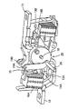
図2を参照すると、本発明の第1の実施形態の回転子組立体20は、各々が符号22で示されるような通路を持つ一対の突きだしシリンダー21A,21Bにより連結される対向配置された一対の回転子板17A,17Bを有する単一組立体として一般的に示されている。回転子板とシリンダーとは、良好な構造的特性および電気的絶縁特性を持つガラス充填熱硬化性樹脂から作られることが好ましく、また、中央作動軸18は、可動接点アーム15と両方の回転子板を通って延びている。
【0009】
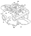
回転子板17A,17Bの各々は、それらの対向する外周上にU字型保持溝28と、符号30で示されるようなラジアル方向に盛り上げられたストッパを持つキャリアスロット29とを含む。対向する一対の接点スプリング23A、23Bは、一端側で、スプリングの一端が取り付けられたスプリングピン26Aによりスロット29に沿って誘導され、他端側ではU字型保持溝28内に捕捉されたスプリングピン27Bにより保持される。対向する一対の接点スプリング24A,24Bは、一端側では、スプリングの一端が取り付けられたスプリングピン26Bによりスロット29に沿って誘導され、他端ではU字型保持溝28内に捕捉されたスプリングピン27Aにより保持される。スプリングピン26A、26B、27A及び27Bは、一対のU字型レバー31A,31Bと協働する。その様子は、U字型レバー31A,31Bを詳細に描いた図3により最もよく理解される。図3では、回転子板17Aが取り除かれ、且つ、シリンダー21A,21Bを断面にして示している。
【0010】
ここで図3を参照すると、U字型レバー31A,31Bは、開口41,42を介して中央軸18と接続し、各々は、湾曲部33,35によってそれぞれ連結された一対の対向するサイドアーム32A、32Bと34A、34Bを有する。接点スプリング23A,23Bの端部におけるスプリングピン26Aは、サイドアーム32A,32Bの端部における開口部36を通って延び、符号39で示されるようにスロット29の面上で終端となる。サイドアーム32A,32Bを連結している湾曲部33は、可動接点アーム15の一端の表面15Bに沿って載置されている。サイドアーム34A,34Bを連結している湾曲部35は、可動接点アームの他端の表面15Aに沿って載置されている。スプリングピン26B,27B及び接点スプリング24A,24Bの関係は、前述の図2で示されたように、回転子板17Aに同様な方法で配置されることが理解される。
【0011】
回転子板17A,17Bと可動接点アーム15の対向する端部の表面15A,15Bとの間にU字型レバー31A,31Bを配置することにより、接点スプリング23A,23Bと24A,24Bの力が相互にフィードバックされる関係で働くことを可能にする。これにより図1の固定接点13A,13Bと可動接点14A,14Bの間に一定の力が作用する。接点スプリングによって可動接点アームの一端で示された力は、その一端に付随する湾曲部との相互作用を介して、可動接点アームの他端に付随する湾曲部に伝達され、可動接点アームの他端に付随する湾曲部の位置を調節する。可動接点アームの一端における一対の固定および可動接点の間の力の増加は、それに応じて他の一対の固定および可動接点の間のそれに相当する力の増加として反映され、それにより関連する回路遮断器の作動寿命を通じて、両方の固定および可動接点の対の間で一定の力をもたらす。
【図面の簡単な説明】
【図1】本発明の一実施形態によるロータリー接点組立体を使用しているロータリー接点回路遮断器内部の正面斜視図である。
【図2】図1の回路遮断器内部に包含された回転子組立体の拡大正面斜視図である。
【図3】図2の回路遮断器内部に包含された回転子組立体で、U字型レバーを極めて詳細に描くために回転子板を取り外した拡大正面斜視図である。
【符号の説明】
11 ラインストラップ
12 負荷ストラップ
13A 固定接点
13B 固定接点
14A 可動接点
14B 可動接点
15 可動接点アーム
16A アークシュート
16B アークシュート
18 軸
19A リンク
19B リンク
20 回転子組立体
25 ピン[0001]
BACKGROUND OF THE INVENTION
The present invention relates to circuit breakers and, more particularly, to a rotary contact arm device for a circuit breaker.
[0002]
[Prior art]
There is a type of circuit breaker having a current breaker module in the rotary contact arm device, whereby the movable contact arm of the circuit breaker is located at the opposite end of the movable contact carrier. This circuit breaker can break the circuit current at a faster rate than a circuit breaker of the type having a movable contact carrier with a contact disposed at one end. US Pat. No. 5,310,971, entitled “Rotary Contact System for Circuit Breakers”, describes fixed contacts attached to the line and load straps of a circuit breaker and opposite ends of a movable contact arm. A rotary contact arm is described that uses a roller between the contact spring and the contact arm to provide a uniform force distribution between the movable contacts disposed on the surface.
[0003]
[Problems to be solved by the invention]
One problem associated with non-uniform force distribution between the stationary contact and the movable contact is that excessive contact on the pair of contacts in that lower forces act in the area along the surface of the stationary contact. Corrosion can occur.
[0004]
[Means for Solving the Problems]
In an exemplary embodiment of the invention, a rotary contact device for a circuit breaker of the type including a pair of contact springs disposed on each side of the rotary contact arm is provided between the rotor and the contact arm. It has contact springs that are interconnected via a letter-shaped lever. In order to ensure a uniform spring force between the fixed contact and the movable contact, the side arm of the U-shaped lever interacts with the outer peripheral surface of the rotor, while the curved portion of the U-shaped lever It interacts with the shape surface of the contact arm.
[0005]
Uniform contact pressure between both fixed and movable contact pairs of the rotary circuit breaker is achieved without inserting a roller between the contact spring and the movable contact arm. In this case, it is particularly advantageous if the rotary circuit breaker is used in a multipole circuit breaker that requires a separate movable contact arm for each of the separated poles.
[0006]
DETAILED DESCRIPTION OF THE INVENTION
Referring to FIG. 1, a circuit breaker internal
[0007]
The flow of electricity through the circuit breaker emanates from the
[0008]
Referring to FIG. 2, the
[0009]
Each of the
[0010]
Referring now to FIG. 3, the U-shaped levers 31A, 31B are connected to the
[0011]
By arranging the U-shaped
[Brief description of the drawings]
FIG. 1 is a front perspective view of an interior of a rotary contact circuit breaker using a rotary contact assembly according to an embodiment of the present invention.
2 is an enlarged front perspective view of a rotor assembly contained within the circuit breaker of FIG. 1; FIG.
FIG. 3 is an enlarged front perspective view of the rotor assembly contained within the circuit breaker of FIG. 2 with the rotor plate removed to depict the U-shaped lever in greater detail.
[Explanation of symbols]
11
Claims (11)
前記回転子板(17A,17B)の間に設けられ、一端において第1の固定接点(13A)の反対側に配置された第1の可動接点(14A)と、前記一端の反対側の一端において第2の固定接点(13B)の近傍に配置された第2の可動接点(14B)とを有する可動接点アーム(15)と、
前記回転子板(17A,17B)と前記可動接点アーム(15)とが一致して回転するように、前記回転子板(17A,17B)と前記可動接点アーム(15)とを通って延びる軸ピン(18)と、
一方の接点スプリング(23A)は前記可動接点アーム(15)の一方の側に配置され、他方の接点スプリング(23B)はその反対側に配置される一対の第1接点スプリング(23A,23B)及び
前記回転子板(17A,17B)の間に設けられ、前記接点アーム(15)上に形成された第1の形状表面(15B)の近傍に配置された湾曲部(33)により一端において連結された一対のサイドアーム(32A,32B)を設け、前記第1および第2の固定および可動接点(14B,13B)の間に一定のスプリング力を作用させるU字型レバー(31A)
を含むことを特徴とする回路遮断器のロータリー接点装置。A pair of opposing circular rotor plates (17A, 17B), each defining a carrier slot (29) on its outer periphery;
A first movable contact (14A) provided between the rotor plates (17A, 17B) and disposed at one end opposite to the first fixed contact (13A) and at one end opposite to the one end A movable contact arm (15) having a second movable contact (14B) disposed in the vicinity of the second fixed contact (13B);
A shaft extending through the rotor plate (17A, 17B) and the movable contact arm (15) so that the rotor plate (17A, 17B) and the movable contact arm (15) rotate in unison. Pin (18),
One contact spring (23A) is disposed on one side of the movable contact arm (15), and the other contact spring (23B) is a pair of first contact springs (23A, 23B) disposed on the opposite side, and Provided between the rotor plates (17A, 17B) and connected at one end by a curved portion (33) disposed in the vicinity of the first shape surface (15B) formed on the contact arm (15). A pair of side arms (32A, 32B) is provided, and a U-shaped lever (31A) for applying a constant spring force between the first and second fixed and movable contacts (14B, 13B).
A rotary contact device for a circuit breaker comprising:
前記ラインおよび負荷ストラップ(11,12)間の過電流伝達に対して発生するアークを消滅するために、第1アークシュート(16B)が前記ラインストラップ(11)の近傍に置かれ、且つ、第2アークシュート(16A)が前記負荷ストラップ(12)の近傍に置かれるような、一対の第1および第2アークシュート(16A,16B)、
一端において、対向する第1の固定接点(13A)の反対側に配置された第1の可動接点(14A)と、前記一端の反対側の一端において、第2の固定接点(13B)の近傍に配置された第2の可動接点(14B)とを定めるような、前記回転子板(17A,17B)の間にある可動接点アーム(15)、
前記回転子板(17A,17B)と前記可動接点アーム(15)とが一致して回転するように、前記回転子板(17A,17B)と前記可動接点アーム(15)とを通って延びる軸ピン(18)、
一方(23A)は前記可動接点アーム(15)の一方の側に配置され、且つ、他方(23B)はその反対側に配置されるような、一対の第1接点スプリング(23A,23B)、及び
前記接点アーム上に形成された第1の形状表面(15B)の近傍に配置された湾曲部(33)により一端において接合された一対のサイドアーム(32A,32B)を定め、前記第1および第2の固定および可動接点(14A,13A)の間に一定のスプリング力を準備するための、前記回転子板(17A,17B)の間に置かれたU字型レバー(31A)
を含むことを特徴とする回路遮断器内部組立体。An electrical circuit, each of which is intermittently connected by a rotary contact device (20) including a pair of opposing circular rotor plates (17A, 17B) that define a conveying groove (29) on its outer periphery; And a load strap (12) arranged for electrical connection with the line strap (11) and for electrical connection with associated electrical equipment. ,
A first arc chute (16B) is placed in the vicinity of the line strap (11) in order to extinguish an arc generated due to overcurrent transmission between the line and the load strap (11, 12), and A pair of first and second arc chutes (16A, 16B) such that a two arc chute (16A) is placed in the vicinity of the load strap (12);
At one end, the first movable contact (14A) disposed on the opposite side of the opposing first fixed contact (13A), and at one end opposite to the one end, in the vicinity of the second fixed contact (13B). A movable contact arm (15) between the rotor plates (17A, 17B), such as to define a second movable contact (14B) disposed;
A shaft extending through the rotor plate (17A, 17B) and the movable contact arm (15) so that the rotor plate (17A, 17B) and the movable contact arm (15) rotate in unison. Pin (18),
A pair of first contact springs (23A, 23B), one (23A) disposed on one side of the movable contact arm (15) and the other (23B) disposed on the opposite side; A pair of side arms (32A, 32B) joined at one end by a curved portion (33) disposed in the vicinity of the first shape surface (15B) formed on the contact arm is defined, and the first and first U-shaped lever (31A) placed between the rotor plates (17A, 17B) for preparing a constant spring force between the two fixed and movable contacts (14A, 13A)
A circuit breaker internal assembly comprising:
Applications Claiming Priority (2)
| Application Number | Priority Date | Filing Date | Title |
|---|---|---|---|
| EP99308745.1 | 1999-11-03 | ||
| EP99308745A EP1098343B1 (en) | 1999-11-03 | 1999-11-03 | Circuit breaker rotary contact arm arrangement |
Publications (2)
| Publication Number | Publication Date |
|---|---|
| JP2001167681A JP2001167681A (en) | 2001-06-22 |
| JP4430809B2 true JP4430809B2 (en) | 2010-03-10 |
Family
ID=8241713
Family Applications (1)
| Application Number | Title | Priority Date | Filing Date |
|---|---|---|---|
| JP2000337128A Expired - Fee Related JP4430809B2 (en) | 1999-11-03 | 2000-11-06 | Circuit breaker rotary contact arm device |
Country Status (6)
| Country | Link |
|---|---|
| US (1) | US6262642B1 (en) |
| EP (1) | EP1098343B1 (en) |
| JP (1) | JP4430809B2 (en) |
| CN (1) | CN1165927C (en) |
| ES (1) | ES2249875T3 (en) |
| HU (1) | HU225422B1 (en) |
Families Citing this family (26)
| Publication number | Priority date | Publication date | Assignee | Title |
|---|---|---|---|---|
| US6366438B1 (en) * | 2000-03-06 | 2002-04-02 | General Electric Company | Circuit interrupter rotary contact arm |
| ITMI20012325A1 (en) * | 2001-11-06 | 2003-05-06 | Abb Service Srl | LOW VOLTAGE SWITCH |
| ITMI20012327A1 (en) * | 2001-11-06 | 2003-05-06 | Abb Service Srl | LOW VOLTAGE SWITCH |
| US7005594B2 (en) * | 2004-04-16 | 2006-02-28 | Ls Industrial Systems Co., Ltd. | Movable contactor assembly of circuit breaker |
| KR100575243B1 (en) * | 2004-04-16 | 2006-05-02 | 엘에스산전 주식회사 | A movable contactor assembly for a mould cased circuit breaker |
| KR100574788B1 (en) * | 2004-10-07 | 2006-04-27 | 엘에스산전 주식회사 | A contactor assembly for a circuit breaker |
| ITMI20042234A1 (en) * | 2004-11-19 | 2005-02-19 | Abb Service Srl | AUTOMATIC SWITCH WITH RELEASE KINEMATISM USED BY MOBILE CONTACT |
| US7297021B1 (en) * | 2006-08-31 | 2007-11-20 | Siemens Energy & Automation, Inc. | Devices, systems, and methods for bypassing an electrical meter |
| ITBG20060054A1 (en) | 2006-10-13 | 2008-04-14 | Abb Service Srl | LOW VOLTAGE DEVICE WITH REINFORCED MOBILE CREW |
| ITBG20060053A1 (en) * | 2006-10-13 | 2008-04-14 | Abb Service Srl | LOW VOLTAGE DEVICE WITH MOBILE CREW WITH HIGH ELECTRODYNAMIC SEALING |
| KR200437069Y1 (en) * | 2006-10-17 | 2007-11-02 | 엘에스산전 주식회사 | Moving conductor of air circuit breaker |
| US7977592B2 (en) | 2007-09-11 | 2011-07-12 | Siemens Industry, Inc. | Double break disconnect/contact system |
| US7566840B2 (en) * | 2007-10-04 | 2009-07-28 | General Electric Company | Contact arm mechanism for circuit breaker |
| CN101692415B (en) * | 2009-05-11 | 2012-05-02 | 江苏辉能电气有限公司 | Revolving double breakpoints structure of low-voltage circuit breaker contact |
| KR101463043B1 (en) * | 2009-09-01 | 2014-11-18 | 엘에스산전 주식회사 | Slide type movable contactor assembly for circuit breaker |
| BR112012005824B1 (en) * | 2009-09-18 | 2020-12-08 | Schneider Electric Industries Sas | unipolar cutting block comprising a rotating contact bridge, cutting device comprising such a block and circuit breaker comprising such a device |
| US8350168B2 (en) | 2010-06-30 | 2013-01-08 | Schneider Electric USA, Inc. | Quad break modular circuit breaker interrupter |
| DE102010035625A1 (en) * | 2010-08-24 | 2012-03-01 | Siemens Aktiengesellschaft | Electric switch and method for mounting a switching unit of an electrical switch |
| CN102024632A (en) * | 2010-12-19 | 2011-04-20 | 浙江达达电器有限公司 | Contact system of low-voltage circuit breaker |
| KR101141537B1 (en) * | 2011-01-03 | 2012-05-04 | 엘에스산전 주식회사 | Movable contactor assembly for current limiting circuit breaker |
| CN103021745B (en) * | 2011-09-26 | 2015-03-25 | 上海电科电器科技有限公司 | Moving contact linkage structure of modularized circuit breaker |
| CN103077858B (en) * | 2013-01-16 | 2015-07-08 | 创奇科技有限公司 | Contact system of circuit breaker |
| US9355798B2 (en) | 2014-08-21 | 2016-05-31 | General Electric Company | System and method for quenching an arc |
| US10118165B2 (en) | 2015-02-04 | 2018-11-06 | Exxonmobil Chemical Patents Inc. | Catalyst compositions and use in heavy aromatics conversion processes |
| US10053403B2 (en) | 2015-02-04 | 2018-08-21 | Exxonmobil Chemical Patents Inc. | Catalyst compositions and their use in transalkylation of heavy aromatics to xylenes |
| EP3696842A1 (en) * | 2019-02-13 | 2020-08-19 | ABB Schweiz AG | Closing switch and switchgear |
Family Cites Families (215)
| Publication number | Priority date | Publication date | Assignee | Title |
|---|---|---|---|---|
| US2340682A (en) | 1942-05-06 | 1944-02-01 | Gen Electric | Electric contact element |
| US2719203A (en) | 1952-05-02 | 1955-09-27 | Westinghouse Electric Corp | Circuit breakers |
| US2937254A (en) | 1957-02-05 | 1960-05-17 | Gen Electric | Panelboard unit |
| US3162739A (en) | 1962-06-25 | 1964-12-22 | Gen Electric | Electric circuit breaker with improved trip means |
| US3158717A (en) | 1962-07-18 | 1964-11-24 | Gen Electric | Electric circuit breaker including stop means for limiting movement of a toggle linkage |
| US3197582A (en) | 1962-07-30 | 1965-07-27 | Fed Pacific Electric Co | Enclosed circuit interrupter |
| DE1227978B (en) | 1963-10-04 | 1966-11-03 | Licentia Gmbh | Electrical switchgear, in particular contactor |
| US3307002A (en) | 1965-02-04 | 1967-02-28 | Texas Instruments Inc | Multipole circuit breaker |
| NL6810433A (en) | 1967-07-24 | 1969-01-28 | ||
| US3631369A (en) | 1970-04-27 | 1971-12-28 | Ite Imperial Corp | Blowoff means for circuit breaker latch |
| US3803455A (en) | 1973-01-02 | 1974-04-09 | Gen Electric | Electric circuit breaker static trip unit with thermal override |
| FR2241868B1 (en) | 1973-08-20 | 1976-06-18 | Merlin Gerin | |
| US3883781A (en) | 1973-09-06 | 1975-05-13 | Westinghouse Electric Corp | Remote controlled circuit interrupter |
| FR2360171A1 (en) | 1976-07-30 | 1978-02-24 | Unelec | CIRCUIT BREAKER CONTROL MECHANISM |
| FR2361737A1 (en) | 1976-08-09 | 1978-03-10 | Unelec | CIRCUIT BREAKER WITH LOCKING DEVICE FOR THE CONTROL HANDLE IN THE EVENT OF WELDING OF THE CONTACTS |
| US4158119A (en) | 1977-07-20 | 1979-06-12 | Gould Inc. | Means for breaking welds formed between circuit breaker contacts |
| US4144513A (en) | 1977-08-18 | 1979-03-13 | Gould Inc. | Anti-rebound latch for current limiting switches |
| FR2410353A1 (en) | 1977-11-28 | 1979-06-22 | Merlin Gerin | Polarised relay for differential circuit breaker - has magnetic yoke having two L=shaped legs, one carrying de-energising coil and other completing loop with permanent magnet |
| US4166988A (en) | 1978-04-19 | 1979-09-04 | General Electric Company | Compact three-pole circuit breaker |
| FR2429487A1 (en) | 1978-06-23 | 1980-01-18 | Merlin Gerin | CIRCUIT BREAKER WITH REMOVABLE TRIGGER BLOCK |
| US4220934A (en) | 1978-10-16 | 1980-09-02 | Westinghouse Electric Corp. | Current limiting circuit breaker with integral magnetic drive device housing and contact arm stop |
| US4255732A (en) | 1978-10-16 | 1981-03-10 | Westinghouse Electric Corp. | Current limiting circuit breaker |
| US4259651A (en) | 1978-10-16 | 1981-03-31 | Westinghouse Electric Corp. | Current limiting circuit interrupter with improved operating mechanism |
| FR2452175A1 (en) | 1979-03-23 | 1980-10-17 | Alsthom Unelec Sa | ELECTRICAL AIR CUT-OFF APPARATUS PROVIDED WITH A SHORT-CIRCUIT INDICATOR DEVICE |
| US4263492A (en) | 1979-09-21 | 1981-04-21 | Westinghouse Electric Corp. | Circuit breaker with anti-bounce mechanism |
| US4297663A (en) | 1979-10-26 | 1981-10-27 | General Electric Company | Circuit breaker accessories packaged in a standardized molded case |
| IT1129691B (en) | 1980-01-31 | 1986-06-11 | Elettromeccanica Spa Cge Comp | RAPID EXTINGUISHING COMPLEX OF THE ELECTRIC ARC IN INTERRUPTION DEVICES SUCH AS ELECTRIC SWITCHES |
| FR2478368A1 (en) | 1980-03-12 | 1981-09-18 | Merlin Gerin | MANEUVER MECHANISM FOR TETRAPOLAR CIRCUIT BREAKER |
| JPS613106Y2 (en) | 1980-04-10 | 1986-01-31 | ||
| US4301342A (en) | 1980-06-23 | 1981-11-17 | General Electric Company | Circuit breaker condition indicator apparatus |
| DE8023509U1 (en) | 1980-08-29 | 1980-11-27 | Siemens Ag, 1000 Berlin Und 8000 Muenchen | Low voltage circuit breaker for locking lever |
| DE3033213C2 (en) | 1980-08-29 | 1982-10-21 | Siemens AG, 1000 Berlin und 8000 München | Low voltage circuit breaker with a locking lever |
| DE3034790A1 (en) | 1980-09-15 | 1982-03-25 | Siemens AG, 1000 Berlin und 8000 München | CIRCUIT BREAKER |
| US4541032A (en) | 1980-10-21 | 1985-09-10 | B/K Patent Development Company, Inc. | Modular electrical shunts for integrated circuit applications |
| JPS57102281U (en) | 1980-12-16 | 1982-06-23 | ||
| DE3047360C2 (en) | 1980-12-16 | 1987-08-20 | Karl Pfisterer Elektrotechnische Spezialartikel Gmbh & Co Kg, 7000 Stuttgart | Switching strip |
| DE3110960A1 (en) | 1981-03-20 | 1982-09-30 | Basf Ag, 6700 Ludwigshafen | ELECTROPHOTOGRAPHIC RECORDING MATERIAL |
| US4360852A (en) | 1981-04-01 | 1982-11-23 | Allis-Chalmers Corporation | Overcurrent and overtemperature protective circuit for power transistor system |
| US4409573A (en) | 1981-04-23 | 1983-10-11 | Siemens-Allis, Inc. | Electromagnetically actuated anti-rebound latch |
| FR2505553A1 (en) | 1981-05-07 | 1982-11-12 | Merlin Gerin | MULTIPOLAR CIRCUIT BREAKER WITH INTERCHANGEABLE MAGNETOTHERMIC TRIGGER |
| FR2506066A1 (en) | 1981-05-18 | 1982-11-19 | Merlin Gerin | MANEUVERING MECHANISM OF A LOW VOLTAGE MULTIPOLAR ELECTRIC CIRCUIT BREAKER |
| FR2512582A1 (en) | 1981-09-10 | 1983-03-11 | Merlin Gerin | Tamperproof differential relay - uses screw-in cover to clip together two modules of earth leakage relay |
| FR2514195A1 (en) | 1981-10-05 | 1983-04-08 | Merlin Gerin | MULTIPOLAR CIRCUIT BREAKER WITH REMOVABLE TRIGGER BLOCK |
| US4435690A (en) | 1982-04-26 | 1984-03-06 | Rte Corporation | Primary circuit breaker |
| US4658322A (en) | 1982-04-29 | 1987-04-14 | The United States Of America As Represented By The Secretary Of The Navy | Arcing fault detector |
| US4470027A (en) | 1982-07-16 | 1984-09-04 | Eaton Corporation | Molded case circuit breaker with improved high fault current interruption capability |
| FR2532793A1 (en) | 1982-09-08 | 1984-03-09 | Merlin Gerin | Short-circuit and differential hybrid trip unit equipped with a current transformer with common homopolar torus. |
| IT8223118V0 (en) | 1982-10-07 | 1982-10-07 | Sace Spa | ELECTRIC SWITCH WITH STOPPING THE CONTROL LEVER STROKE IN CASE OF WELDING THE CONTACTS. |
| US4492941A (en) | 1983-02-18 | 1985-01-08 | Heinemann Electric Company | Circuit breaker comprising parallel connected sections |
| US4488133A (en) | 1983-03-28 | 1984-12-11 | Siemens-Allis, Inc. | Contact assembly including spring loaded cam follower overcenter means |
| FR2547122B1 (en) | 1983-06-03 | 1985-07-05 | Merlin Gerin | SELECTIVE ELECTRONIC TRIGGER ASSOCIATED WITH A LIMITING CIRCUIT BREAKER |
| JPS6068524A (en) | 1983-09-21 | 1985-04-19 | 三菱電機株式会社 | Circuit breaker |
| FR2553929B1 (en) | 1983-10-21 | 1986-08-01 | Merlin Gerin | CONTROL MECHANISM OF A LOW VOLTAGE MULTIPOLAR CIRCUIT BREAKER |
| FR2553943B1 (en) | 1983-10-24 | 1986-04-11 | Merlin Gerin | RESIDUAL DIFFERENTIAL DEVICE PROVIDED WITH A DEVICE FOR MONITORING THE ELECTRONIC POWER SOURCE |
| DE3347120A1 (en) | 1983-12-22 | 1985-07-11 | Siemens AG, 1000 Berlin und 8000 München | ELECTRO-DYNAMIC OPENING CONTACT SYSTEM |
| IT1173269B (en) | 1984-02-15 | 1987-06-18 | Cge Comp Gen Elettromecc | COMBINATION OF COUPLING CONNECTION AND RELEASE DEVICE TO AVOID THE CLOSING OF THE CONTACTS OF AN AUTOMATIC SWITCH AFTER AN OPENING DUE TO SHORT CIRCUIT |
| US4550360A (en) | 1984-05-21 | 1985-10-29 | General Electric Company | Circuit breaker static trip unit having automatic circuit trimming |
| US4672501A (en) | 1984-06-29 | 1987-06-09 | General Electric Company | Circuit breaker and protective relay unit |
| US4589052A (en) | 1984-07-17 | 1986-05-13 | General Electric Company | Digital I2 T pickup, time bands and timing control circuits for static trip circuit breakers |
| JPS6132324A (en) | 1984-07-20 | 1986-02-15 | 富士電機株式会社 | Internal accessory mounting structure of wiring breaker |
| IT1175633B (en) | 1984-08-14 | 1987-07-15 | Cge Spa | Contact arrangement for current limiting circuit breaker |
| DE3431288A1 (en) | 1984-08-23 | 1986-03-06 | Siemens AG, 1000 Berlin und 8000 München | CONTACT ARRANGEMENT FOR LOW VOLTAGE CIRCUIT BREAKERS WITH A TWO-ARM CONTACT LEVER |
| US4631625A (en) | 1984-09-27 | 1986-12-23 | Siemens Energy & Automation, Inc. | Microprocessor controlled circuit breaker trip unit |
| US4612430A (en) | 1984-12-21 | 1986-09-16 | Square D Company | Anti-rebound latch |
| FR2578113B1 (en) | 1985-02-25 | 1988-04-15 | Merlin Gerin | DIGITAL STATIC TRIGGER WITH OPTIONAL FUNCTIONS FOR AN ELECTRIC CIRCUIT BREAKER |
| FR2578091B1 (en) | 1985-02-25 | 1988-08-05 | Merlin Gerin | CIRCUIT BREAKER WITH DIGITAL STATIC TRIGGER PROVIDED WITH A CALIBRATION CIRCUIT |
| FR2578090B1 (en) | 1985-02-25 | 1989-12-01 | Merlin Gerin | CIRCUIT BREAKER WITH DIGITAL STATIC TRIGGER WITH REVERSE TIME TRIGGERING FUNCTION |
| FR2578112B1 (en) | 1985-02-25 | 1988-03-18 | Merlin Gerin | CIRCUIT BREAKER WITH STATIC TRIGGER WITH DIGITAL PROCESSING CHAIN SHUNTE BY AN ANALOGUE PROCESSING CHAIN |
| FR2578092B1 (en) | 1985-02-25 | 1987-03-06 | Merlin Gerin | CIRCUIT BREAKER WITH STATIC TRIGGER WITH SAMPLING AND LOCK AT THE LAST SIGNAL CRETE |
| FR2578093B1 (en) | 1985-02-27 | 1987-03-06 | Merlin Gerin | UNIPOLAR AND NEUTRAL DIFFERENTIAL CIRCUIT BREAKER |
| US4642431A (en) | 1985-07-18 | 1987-02-10 | Westinghouse Electric Corp. | Molded case circuit breaker with a movable electrical contact positioned by a camming spring loaded clip |
| FR2589627B1 (en) | 1985-10-31 | 1988-08-26 | Merlin Gerin | CONTROL MECHANISM FOR LOW VOLTAGE ELECTRIC CIRCUIT BREAKER |
| EP0225207B1 (en) | 1985-10-31 | 1991-05-15 | Merlin Gerin | Cinematic transmission chain between the control mechanism and the poles of an electric circuit breaker with a moulded insulating casing |
| DE3688838T2 (en) | 1986-01-10 | 1994-03-03 | Merlin Gerin | Static release with test circuit for electrical circuit breakers. |
| FR2592998B1 (en) | 1986-01-10 | 1988-03-18 | Merlin Gerin | TEST CIRCUIT FOR AN ELECTRONIC TRIGGER OF A DIFFERENTIAL CIRCUIT BREAKER. |
| ES2020284B3 (en) | 1986-02-28 | 1991-08-01 | Merlin Gerin | CURRENT CUTTING DEVICE WITH STATIC SWITCH AND PROTECTION CIRCUIT BREAKER. |
| FR2596576B1 (en) | 1986-03-26 | 1988-05-27 | Merlin Gerin | SELF-BLOWING ELECTRIC CIRCUIT BREAKER WITH IMPROVED DIELECTRIC HOLD |
| FR2598266B1 (en) | 1986-04-30 | 1994-02-18 | Merlin Et Gerin | INSTANT STATIC TRIGGER FOR A LIMITING CIRCUIT BREAKER |
| FR2602610B1 (en) | 1986-08-08 | 1994-05-20 | Merlin Et Gerin | STATIC TRIGGER OF AN ELECTRIC CIRCUIT BREAKER WITH CONTACT WEAR INDICATOR |
| FR2604294B1 (en) | 1986-09-23 | 1994-05-20 | Merlin Et Gerin | MULTIPOLAR DIFFERENTIAL CIRCUIT BREAKER WITH MODULAR ASSEMBLY |
| FR2604295B1 (en) | 1986-09-23 | 1988-12-02 | Merlin Gerin | ELECTRICAL DIFFERENTIAL PROTECTION DEVICE WITH TEST CIRCUIT |
| US4675481A (en) | 1986-10-09 | 1987-06-23 | General Electric Company | Compact electric safety switch |
| US4733211A (en) | 1987-01-13 | 1988-03-22 | General Electric Company | Molded case circuit breaker crossbar assembly |
| FR2612347B1 (en) | 1987-03-09 | 1989-05-26 | Merlin Gerin | STATIC TRIGGER COMPRISING A HOMOPOLAR CURRENT DETECTION CIRCUIT |
| EP0313106B1 (en) | 1987-03-12 | 1992-12-16 | Merlin Gerin Limited | Electrical switchgear |
| GB8705885D0 (en) | 1987-03-12 | 1987-04-15 | Y S Securities Ltd | Electrical switchgear |
| FR2615322B1 (en) | 1987-05-11 | 1989-06-30 | Merlin Gerin | TRIP BAR OF A MULTIPOLAR CIRCUIT BREAKER ASSOCIATED WITH AN AUXILIARY TRIGGER BLOCK |
| FR2615323B1 (en) | 1987-05-11 | 1989-06-30 | Merlin Gerin | MODULAR CIRCUIT BREAKER WITH AUXILIARY TRIGGER BLOCK ASSOCIATED WITH A MULTIPOLAR CIRCUIT BREAKER |
| FR2616583B1 (en) | 1987-06-09 | 1995-01-06 | Merlin Gerin | CONTROL MECHANISM OF A MINIATURE ELECTRIC CIRCUIT BREAKER |
| GB8713791D0 (en) | 1987-06-12 | 1987-07-15 | Bicc Plc | Electric circuit breaking apparatus |
| FR2616957A1 (en) | 1987-06-18 | 1988-12-23 | Merlin Gerin | HIGH PRESSURE ARC EXTINGUISHING CHAMBER |
| FR2617633B1 (en) | 1987-07-02 | 1989-11-17 | Merlin Gerin | CIRCUIT BREAKER WITH ROTATING ARC AND EXPANSION |
| FR2621170A1 (en) | 1987-09-25 | 1989-03-31 | Merlin Gerin | BREAKER-LIMIT |
| EP0309923B1 (en) | 1987-10-01 | 1994-12-14 | CGE- COMPAGNIA GENERALE ELETTROMECCANICA S.p.A. | Improved contact arrangement for a current limiting circuit breaker adapted to be actuated both manually and by an actuating electromagnet |
| FR2621748B1 (en) | 1987-10-09 | 1996-07-05 | Merlin Gerin | STATIC TRIGGER OF A MOLDED CASE CIRCUIT BREAKER |
| FR2622347B1 (en) | 1987-10-26 | 1995-04-14 | Merlin Gerin | CUTTING DEVICE FOR A MULTIPOLAR CIRCUIT BREAKER WITH DOUBLE ROTARY CONTACT |
| FR2622737B1 (en) | 1987-11-04 | 1995-04-14 | Merlin Gerin | SELF-EXPANSIONAL ELECTRIC CIRCUIT BREAKER WITH VARIABLE EXTINCTION CHAMBER VOLUME |
| FR2624649B1 (en) | 1987-12-10 | 1990-04-06 | Merlin Gerin | HIGH CALIBER MULTIPOLAR CIRCUIT BREAKER CONSISTING OF TWO ADJUSTED BOXES |
| FR2624650B1 (en) | 1987-12-10 | 1990-04-06 | Merlin Gerin | MULTIPOLAR CIRCUIT BREAKER WITH HIGH CALIBER MOLDED HOUSING |
| FR2624666B1 (en) | 1987-12-10 | 1990-04-06 | Merlin Gerin | |
| US4831221A (en) | 1987-12-16 | 1989-05-16 | General Electric Company | Molded case circuit breaker auxiliary switch unit |
| DE3802184A1 (en) | 1988-01-26 | 1989-08-03 | Licentia Gmbh | LOW VOLTAGE SWITCH WITH LOCKING LOBS |
| FR2626713B1 (en) | 1988-01-28 | 1990-06-01 | Merlin Gerin | ELECTROMAGNETIC TRIGGER WITH TRIGGER THRESHOLD ADJUSTMENT |
| FR2626724B1 (en) | 1988-01-28 | 1993-02-12 | Merlin Gerin | STATIC TRIGGER COMPRISING AN INSTANTANEOUS TRIGGER CIRCUIT INDEPENDENT OF THE SUPPLY VOLTAGE |
| FR2628259A1 (en) | 1988-03-01 | 1989-09-08 | Merlin Gerin | ELECTRICAL SHUT-OFF CIRCUIT BREAKER BY SHOCKPING OR EXPANSION OF INSULATING GAS |
| FR2628262B1 (en) | 1988-03-04 | 1995-05-12 | Merlin Gerin | CONTROL MECHANISM OF A TRIGGERING AUXILIARY BLOCK FOR MODULAR CIRCUIT BREAKER |
| FR2630256B1 (en) | 1988-04-14 | 1995-06-23 | Merlin Gerin | HIGH SENSITIVITY ELECTROMAGNETIC TRIGGER |
| FR2631485B1 (en) | 1988-05-13 | 1995-06-02 | Merlin Gerin | MINIATURE CIRCUIT BREAKER CONTROL MECHANISM WITH CONTACT WELDING INDICATOR |
| FR2632771B1 (en) | 1988-06-10 | 1990-08-31 | Merlin Gerin | LOW VOLTAGE LIMITER CIRCUIT BREAKER WITH WATERPROOF CUTTING CHAMBER |
| IT213976Z2 (en) | 1988-06-23 | 1990-03-05 | Cge Spa | STRUCTURE OF ELECTRIC CONTACTS IN WHICH THE AXIAL DRIVE FORCE IS ONLY A SMALL FRACTION OF THE FORCE EXERCISED ON THE CONTACTS. |
| US4870531A (en) | 1988-08-15 | 1989-09-26 | General Electric Company | Circuit breaker with removable display and keypad |
| FR2638909B1 (en) | 1988-11-04 | 1995-03-31 | Merlin Gerin | DIFFERENTIAL TRIGGER WITH TEST CIRCUIT AND SELF-PROTECTED OPENING REMOTE CONTROL |
| FR2639148B1 (en) | 1988-11-16 | 1991-08-02 | Merlin Gerin | MAGNETIC TRIGGER WITH WIDE TRIGGER THRESHOLD ADJUSTMENT RANGE |
| FR2639760B1 (en) | 1988-11-28 | 1996-02-09 | Merlin Gerin | MODULAR UR CIRCUIT BREAKER EQUIPPED WITH AN INDEPENDENT OR AUTOMATIC RESET TRIGGERING AUXILIARY BLOCK |
| FR2640422B1 (en) | 1988-12-14 | 1996-04-05 | Merlin Gerin | MODULAR ASSEMBLY OF A MULTIPOLAR DIFFERENTIAL CIRCUIT BREAKER |
| DE3843277A1 (en) | 1988-12-22 | 1990-06-28 | Bosch Gmbh Robert | Power output stage for electromagnetic loads |
| FR2641898B1 (en) | 1989-01-17 | 1991-03-15 | Merlin Gerin | SELF-BLOWING ELECTRIC CIRCUIT BREAKER |
| US4884164A (en) | 1989-02-01 | 1989-11-28 | General Electric Company | Molded case electronic circuit interrupter |
| EP0385886B1 (en) | 1989-02-27 | 1994-11-09 | Merlin Gerin | Circuit breaker with a rotating arc and with a centrifugal effect of the extinguishing gas |
| FR2644624B1 (en) | 1989-03-17 | 1996-03-22 | Merlin Gerin | ELECTRICAL CIRCUIT BREAKER WITH SELF-EXPANSION AND INSULATING GAS |
| US5200724A (en) | 1989-03-30 | 1993-04-06 | Westinghouse Electric Corp. | Electrical circuit breaker operating handle block |
| US4951019A (en) | 1989-03-30 | 1990-08-21 | Westinghouse Electric Corp. | Electrical circuit breaker operating handle block |
| US5004878A (en) | 1989-03-30 | 1991-04-02 | General Electric Company | Molded case circuit breaker movable contact arm arrangement |
| FR2646282B1 (en) | 1989-04-20 | 1996-03-22 | Merlin Gerin | MANUAL TEST AUXILIARY SWITCH FOR MODULAR CIRCUIT BREAKER |
| GB2233155A (en) | 1989-04-27 | 1991-01-02 | Delta Circuits Protection | Electric circuit breaker |
| SE461557B (en) | 1989-04-28 | 1990-02-26 | Asea Brown Boveri | CONTACT DEVICE FOR ELECTRICAL CONNECTORS |
| FR2646738B1 (en) | 1989-05-03 | 1991-07-05 | Merlin Gerin | STATIC TRIGGER FOR A THREE-PHASE NETWORK PROTECTION CIRCUIT BREAKER FOR DETECTING THE TYPE OF FAULT |
| IT1230203B (en) | 1989-05-25 | 1991-10-18 | Bassani Spa | AUTOMATIC SWITCH FOR MAGNETOTHERMAL PROTECTION WITH HIGH INTERRUPTION POWER. |
| FR2648952B1 (en) | 1989-06-26 | 1991-09-13 | Merlin Gerin | LIMITING CIRCUIT BREAKER HAVING AN ELECTROMAGNETIC EFFECT CONTACT DELAY RETARDER |
| FR2649259B1 (en) | 1989-07-03 | 1991-09-13 | Merlin Gerin | STATIC TRIGGER COMPRISING AN EARTH PROTECTION DESENSITIZATION SYSTEM |
| US4943888A (en) | 1989-07-10 | 1990-07-24 | General Electric Company | Electronic circuit breaker using digital circuitry having instantaneous trip capability |
| FR2650434B1 (en) | 1989-07-26 | 1995-11-24 | Merlin Gerin | LOW VOLTAGE CIRCUIT BREAKER WITH MULTIPLE CONTACTS AND HIGH CURRENTS |
| DE8909831U1 (en) | 1989-08-16 | 1990-12-20 | Siemens Ag, 8000 Muenchen, De | |
| FR2651915B1 (en) | 1989-09-13 | 1991-11-08 | Merlin Gerin | ULTRA-FAST STATIC CIRCUIT BREAKER WITH GALVANIC ISOLATION. |
| FR2651919B1 (en) | 1989-09-13 | 1995-12-15 | Merlin Gerin | CIRCUIT BREAKER COMPRISING AN ELECTRONIC TRIGGER. |
| FR2655766B1 (en) | 1989-12-11 | 1993-09-03 | Merlin Gerin | MEDIUM VOLTAGE HYBRID CIRCUIT BREAKER. |
| FR2659177B1 (en) | 1990-03-01 | 1992-09-04 | Merlin Gerin | CURRENT SENSOR FOR AN ELECTRONIC TRIGGER OF AN ELECTRIC CIRCUIT BREAKER. |
| FR2660794B1 (en) | 1990-04-09 | 1996-07-26 | Merlin Gerin | CONTROL MECHANISM OF AN ELECTRIC CIRCUIT BREAKER. |
| FR2661776B1 (en) | 1990-05-04 | 1996-05-10 | Merlin Gerin | INSTANT TRIGGER OF A CIRCUIT BREAKER. |
| IT219700Z2 (en) | 1990-05-29 | 1993-04-26 | Cge Spa | CLAMPING FIXING DEVICE WITH SNAP LOCK FOR CONTROL AND / OR SIGNALING UNIT |
| FR2663175A1 (en) | 1990-06-12 | 1991-12-13 | Merlin Gerin | STATIC SWITCH. |
| FR2663457B1 (en) | 1990-06-14 | 1996-06-07 | Merlin Gerin | ELECTRICAL CIRCUIT BREAKER WITH SELF-EXPANSION AND ARC ROTATION. |
| FR2663780B1 (en) | 1990-06-26 | 1992-09-11 | Merlin Gerin | HIGH VOLTAGE CIRCUIT BREAKER WITH GAS INSULATION AND PNEUMATIC CONTROL MECHANISM. |
| FR2665571B1 (en) | 1990-08-01 | 1992-10-16 | Merlin Gerin | ELECTRIC CIRCUIT BREAKER WITH ROTATING ARC AND SELF - EXPANSION. |
| US5120921A (en) | 1990-09-27 | 1992-06-09 | Siemens Energy & Automation, Inc. | Circuit breaker including improved handle indication of contact position |
| FR2671228B1 (en) | 1990-12-26 | 1996-07-26 | Merlin Gerin | CIRCUIT BREAKER COMPRISING AN INTERFACE CARD WITH A TRIGGER. |
| US5262744A (en) | 1991-01-22 | 1993-11-16 | General Electric Company | Molded case circuit breaker multi-pole crossbar assembly |
| US5140115A (en) | 1991-02-25 | 1992-08-18 | General Electric Company | Circuit breaker contacts condition indicator |
| US5184717A (en) | 1991-05-29 | 1993-02-09 | Westinghouse Electric Corp. | Circuit breaker with welded contacts |
| FR2677168B1 (en) | 1991-06-03 | 1994-06-17 | Merlin Gerin | MEDIUM VOLTAGE CIRCUIT BREAKER WITH REDUCED CONTROL ENERGY. |
| FR2679039B1 (en) | 1991-07-09 | 1993-11-26 | Merlin Gerin | ELECTRICAL ENERGY DISTRIBUTION DEVICE WITH INSULATION CONTROL. |
| FR2682529B1 (en) | 1991-10-10 | 1993-11-26 | Merlin Gerin | CIRCUIT BREAKER WITH SELECTIVE LOCKING. |
| FR2682531B1 (en) | 1991-10-15 | 1993-11-26 | Merlin Gerin | MULTIPOLAR CIRCUIT BREAKER WITH SINGLE POLE BLOCKS. |
| FR2682530B1 (en) * | 1991-10-15 | 1993-11-26 | Merlin Gerin | RANGE OF LOW VOLTAGE CIRCUIT BREAKERS WITH MOLDED HOUSING. |
| FR2682808B1 (en) | 1991-10-17 | 1997-01-24 | Merlin Gerin | HYBRID CIRCUIT BREAKER WITH AXIAL BLOWING COIL. |
| FR2682807B1 (en) | 1991-10-17 | 1997-01-24 | Merlin Gerin | ELECTRIC CIRCUIT BREAKER WITH TWO VACUUM CARTRIDGES IN SERIES. |
| US5341191A (en) | 1991-10-18 | 1994-08-23 | Eaton Corporation | Molded case current limiting circuit breaker |
| US5260533A (en) | 1991-10-18 | 1993-11-09 | Westinghouse Electric Corp. | Molded case current limiting circuit breaker |
| TW200593B (en) | 1991-10-24 | 1993-02-21 | Fuji Electric Co Ltd | |
| FR2683089B1 (en) * | 1991-10-29 | 1993-12-31 | Merlin Gerin | OPERATING MECHANISM FOR TETRAPOLAR CIRCUIT BREAKER. |
| FR2683675B1 (en) | 1991-11-13 | 1993-12-31 | Merlin Gerin | METHOD AND DEVICE FOR ADJUSTING A TECHNICAL TRIGGER WITH BILAME. |
| FR2683938B1 (en) | 1991-11-20 | 1993-12-31 | Gec Alsthom Sa | CIRCUIT BREAKER WITH SULFUR HEXAFLUORIDE AND APPLICATIONS TO CELLS AND PREFABRICATED STATIONS AND SUBSTATIONS. |
| FR2683940B1 (en) | 1991-11-20 | 1993-12-31 | Gec Alsthom Sa | MEDIUM VOLTAGE CIRCUIT BREAKER FOR INDOOR OR OUTDOOR USE. |
| US5172087A (en) | 1992-01-31 | 1992-12-15 | General Electric Company | Handle connector for multi-pole circuit breaker |
| FR2687250A1 (en) | 1992-02-07 | 1993-08-13 | Merlin Gerin | MULTIPLE CONTACTING CUTTING DEVICE. |
| FR2687249B1 (en) | 1992-02-07 | 1994-04-01 | Merlin Gerin | CONTROL MECHANISM OF A MOLDED BOX CIRCUIT BREAKER. |
| FR2688625B1 (en) * | 1992-03-13 | 1997-05-09 | Merlin Gerin | CONTACT OF A MOLDED BOX CIRCUIT BREAKER |
| FR2688626B1 (en) * | 1992-03-13 | 1994-05-06 | Merlin Gerin | CIRCUIT BREAKER WITH MOLDED BOX WITH BRIDGE OF BRAKE CONTACTS AT THE END OF PULSE STROKE. |
| FR2690563B1 (en) | 1992-04-23 | 1997-05-09 | Merlin Gerin | PLUG-IN CIRCUIT BREAKER WITH MOLDED HOUSING. |
| FR2690560B1 (en) | 1992-04-23 | 1997-05-09 | Merlin Gerin | DEVICE FOR MECHANICAL INTERLOCKING OF TWO MOLDED BOX CIRCUIT BREAKERS. |
| US5198956A (en) | 1992-06-19 | 1993-03-30 | Square D Company | Overtemperature sensing and signaling circuit |
| FR2693027B1 (en) | 1992-06-30 | 1997-04-04 | Merlin Gerin | SELF-EXPANSION SWITCH OR CIRCUIT BREAKER. |
| US5552755A (en) | 1992-09-11 | 1996-09-03 | Eaton Corporation | Circuit breaker with auxiliary switch actuated by cascaded actuating members |
| KR940007922A (en) | 1992-09-28 | 1994-04-28 | 기타오카 다카시 | Circuit breaker |
| FR2696275B1 (en) | 1992-09-28 | 1994-10-28 | Merlin Gerin | Molded case circuit breaker with interchangeable trip units. |
| FR2696276B1 (en) | 1992-09-29 | 1994-12-02 | Merlin Gerin | Molded case circuit breaker with auxiliary contacts. |
| FR2696866B1 (en) | 1992-10-13 | 1994-12-02 | Merlin Gerin | Three-position switch actuation mechanism. |
| DE4234619C2 (en) | 1992-10-14 | 1994-09-22 | Kloeckner Moeller Gmbh | Overload relay to be combined with contactors |
| FR2697669B1 (en) | 1992-10-29 | 1995-01-06 | Merlin Gerin | Auxiliary unit drawout circuit breaker. |
| FR2697670B1 (en) | 1992-11-04 | 1994-12-02 | Merlin Gerin | Relay constituting a mechanical actuator to trip a circuit breaker or a differential switch. |
| US5296664A (en) | 1992-11-16 | 1994-03-22 | Westinghouse Electric Corp. | Circuit breaker with positive off protection |
| FR2699324A1 (en) | 1992-12-11 | 1994-06-17 | Gen Electric | Auxiliary compact switch for circuit breaker - has casing placed inside circuit breaker box and housing lever actuated by button of microswitch and driven too its original position by spring |
| DE4334577C1 (en) | 1993-10-11 | 1995-03-30 | Kloeckner Moeller Gmbh | Contact system for a current limiting unit |
| FR2701159B1 (en) | 1993-02-03 | 1995-03-31 | Merlin Gerin | Mechanical and electrical locking device for a remote control unit for modular circuit breaker. |
| FR2701617B1 (en) | 1993-02-16 | 1995-04-14 | Merlin Gerin | Circuit breaker with remote control and sectioning function. |
| DE69412880T2 (en) | 1993-02-16 | 1999-03-11 | Schneider Electric Sa | Rotary actuator for a circuit breaker |
| FR2701596B1 (en) | 1993-02-16 | 1995-04-14 | Merlin Gerin | Remote control circuit breaker with reset cam. |
| US5351024A (en) * | 1993-03-08 | 1994-09-27 | Eaton Corporation | Electrical contactor and interrupter employing a rotary disc |
| DK0616347T3 (en) | 1993-03-17 | 1998-10-07 | Ellenberger & Poensgen | Multi-pole safety switch |
| DE69406334T2 (en) | 1993-03-25 | 1998-02-26 | Schneider Electric Sa | Switchgear |
| FR2703507B1 (en) | 1993-04-01 | 1995-06-02 | Merlin Gerin | Circuit breaker with a removable calibration device. |
| US5479143A (en) | 1993-04-07 | 1995-12-26 | Merlin Gerin | Multipole circuit breaker with modular assembly |
| FR2703824B1 (en) | 1993-04-07 | 1995-05-12 | Merlin Gerin | Multipolar limiter circuit breaker with electrodynamic repulsion. |
| FR2703823B1 (en) | 1993-04-08 | 1995-05-12 | Merlin Gerin | Magneto-thermal trip module. |
| FR2704090B1 (en) | 1993-04-16 | 1995-06-23 | Merlin Gerin | AUXILIARY TRIGGER FOR CIRCUIT BREAKER. |
| FR2704091B1 (en) | 1993-04-16 | 1995-06-02 | Merlin Gerin | Device for adjusting the tripping threshold of a multipole circuit breaker. |
| FR2704354B1 (en) | 1993-04-20 | 1995-06-23 | Merlin Gerin | CONTROL MECHANISM OF A MODULAR ELECTRIC CIRCUIT BREAKER. |
| DE9308495U1 (en) | 1993-06-07 | 1994-10-20 | Weber Ag | Single or multi-pole NH fuse |
| FR2707792B1 (en) | 1993-07-02 | 1995-09-01 | Telemecanique | Control and / or signaling unit with terminals. |
| US5361052A (en) | 1993-07-02 | 1994-11-01 | General Electric Company | Industrial-rated circuit breaker having universal application |
| GB9313928D0 (en) | 1993-07-06 | 1993-08-18 | Fenner Co Ltd J H | Improvements in and relating to electromechanical relays |
| DE4337344B4 (en) | 1993-11-02 | 2005-08-25 | Moeller Gmbh | Current limiting contact system for circuit breakers |
| FR2714771B1 (en) | 1994-01-06 | 1996-02-02 | Merlin Gerin | Differential protection device for a power transformer. |
| FR2715517B1 (en) | 1994-01-26 | 1996-03-22 | Merlin Gerin | Differential trip unit. |
| DE9401785U1 (en) | 1994-02-03 | 1995-07-20 | Kloeckner Moeller Gmbh | Key switch with a locking mechanism |
| US5485343A (en) | 1994-02-22 | 1996-01-16 | General Electric Company | Digital circuit interrupter with battery back-up facility |
| US5424701A (en) | 1994-02-25 | 1995-06-13 | General Electric | Operating mechanism for high ampere-rated circuit breakers |
| DE4408234C1 (en) | 1994-03-11 | 1995-06-14 | Kloeckner Moeller Gmbh | Housing with accessories for power switch |
| USD367265S (en) | 1994-07-15 | 1996-02-20 | Mitsubishi Denki Kabushiki Kaisha | Circuit breaker for distribution |
| IT1274993B (en) | 1994-09-01 | 1997-07-29 | Abb Elettrocondutture Spa | BASIC ELECTRONIC CIRCUIT FOR DIFFERENTIAL TYPE SWITCHES DEPENDENT ON THE MAINS VOLTAGE |
| US5585609A (en) | 1994-09-28 | 1996-12-17 | Siemens Energy & Automation, Inc. | Circuit breaker with movable main contact multi-force-level biasing element |
| US5519561A (en) | 1994-11-08 | 1996-05-21 | Eaton Corporation | Circuit breaker using bimetal of thermal-magnetic trip to sense current |
| US5534835A (en) | 1995-03-30 | 1996-07-09 | Siemens Energy & Automation, Inc. | Circuit breaker with molded cam surfaces |
| US5608367A (en) | 1995-11-30 | 1997-03-04 | Eaton Corporation | Molded case circuit breaker with interchangeable trip unit having bimetal assembly which registers with permanent heater transformer airgap |
| IT1292453B1 (en) * | 1997-07-02 | 1999-02-08 | Aeg Niederspannungstech Gmbh | ROTATING GROUP OF CONTACTS FOR HIGH FLOW SWITCHES |
-
1999
- 1999-11-03 ES ES99308745T patent/ES2249875T3/en not_active Expired - Lifetime
- 1999-11-03 EP EP99308745A patent/EP1098343B1/en not_active Expired - Lifetime
- 1999-12-30 US US09/475,374 patent/US6262642B1/en not_active Expired - Fee Related
-
2000
- 2000-11-03 HU HU0004277A patent/HU225422B1/en not_active IP Right Cessation
- 2000-11-03 CN CNB001347063A patent/CN1165927C/en not_active Expired - Fee Related
- 2000-11-06 JP JP2000337128A patent/JP4430809B2/en not_active Expired - Fee Related
Also Published As
| Publication number | Publication date |
|---|---|
| US6262642B1 (en) | 2001-07-17 |
| HU0004277D0 (en) | 2001-01-29 |
| EP1098343B1 (en) | 2005-09-21 |
| HU225422B1 (en) | 2006-11-28 |
| HUP0004277A2 (en) | 2001-09-28 |
| CN1165927C (en) | 2004-09-08 |
| EP1098343A1 (en) | 2001-05-09 |
| ES2249875T3 (en) | 2006-04-01 |
| HUP0004277A3 (en) | 2001-11-28 |
| JP2001167681A (en) | 2001-06-22 |
| CN1296276A (en) | 2001-05-23 |
Similar Documents
| Publication | Publication Date | Title |
|---|---|---|
| JP4430809B2 (en) | Circuit breaker rotary contact arm device | |
| JP4115000B2 (en) | Breaker | |
| KR100574788B1 (en) | A contactor assembly for a circuit breaker | |
| US5793270A (en) | Circuit breaker with latch preventing rebound of blow open contact arm | |
| US5912605A (en) | Circuit breaker with automatic catch to prevent rebound of blow open contact arm | |
| EP1109189B1 (en) | Circuit breaker rotary contact arm arrangement | |
| CN102592896B (en) | Movable contactor assembly for current limiting type circuit breaker | |
| US3343108A (en) | High speed circuit interrupter using magnetic blowoff and means for decreasing the inertial effects during interruption | |
| JP2000164106A (en) | Mechanism of multipolar circuit breaker | |
| JP3814671B2 (en) | Circuit breaker | |
| JP2010086959A (en) | Contact arm assembly and method for assembling contact arm assembly | |
| JPH04351824A (en) | Breaker | |
| JP4119650B2 (en) | Circuit breaker | |
| US3940723A (en) | Instantaneously tripping device for circuit interrupter | |
| JP2570895B2 (en) | Breaker | |
| US3602676A (en) | Knife blade switch with toggle operating means and means for fastening the knife blade to a tie bar | |
| CN216928457U (en) | Pressure balance's circuit breaker rotation type double break point moving contact system | |
| CN215869207U (en) | Contact system of universal circuit breaker | |
| CN220085866U (en) | Operating mechanism and isolating switch | |
| US4160142A (en) | Circuit breaker main and disconnect contact structure | |
| CN220710154U (en) | Static contact locking device for molded case circuit breaker | |
| JP4262349B2 (en) | Multipole circuit breaker | |
| CN116487235A (en) | Pressure balance breaker rotary double-breakpoint moving contact system | |
| CN113936976A (en) | Circuit breaker rotary type double-breakpoint moving contact system and circuit breaker | |
| JP4629281B2 (en) | Circuit breaker |
Legal Events
| Date | Code | Title | Description |
|---|---|---|---|
| A711 | Notification of change in applicant |
Free format text: JAPANESE INTERMEDIATE CODE: A711 Effective date: 20040126 |
|
| A521 | Written amendment |
Free format text: JAPANESE INTERMEDIATE CODE: A821 Effective date: 20040126 |
|
| A521 | Written amendment |
Free format text: JAPANESE INTERMEDIATE CODE: A523 Effective date: 20040303 |
|
| RD12 | Notification of acceptance of power of sub attorney |
Free format text: JAPANESE INTERMEDIATE CODE: A7432 Effective date: 20040305 |
|
| A521 | Written amendment |
Free format text: JAPANESE INTERMEDIATE CODE: A821 Effective date: 20040305 |
|
| A621 | Written request for application examination |
Free format text: JAPANESE INTERMEDIATE CODE: A621 Effective date: 20070821 |
|
| A977 | Report on retrieval |
Free format text: JAPANESE INTERMEDIATE CODE: A971007 Effective date: 20091127 |
|
| TRDD | Decision of grant or rejection written | ||
| A01 | Written decision to grant a patent or to grant a registration (utility model) |
Free format text: JAPANESE INTERMEDIATE CODE: A01 Effective date: 20091215 |
|
| A01 | Written decision to grant a patent or to grant a registration (utility model) |
Free format text: JAPANESE INTERMEDIATE CODE: A01 |
|
| A61 | First payment of annual fees (during grant procedure) |
Free format text: JAPANESE INTERMEDIATE CODE: A61 Effective date: 20091218 |
|
| FPAY | Renewal fee payment (event date is renewal date of database) |
Free format text: PAYMENT UNTIL: 20121225 Year of fee payment: 3 |
|
| R150 | Certificate of patent or registration of utility model |
Free format text: JAPANESE INTERMEDIATE CODE: R150 |
|
| LAPS | Cancellation because of no payment of annual fees |