EP0309923B1 - Improved contact arrangement for a current limiting circuit breaker adapted to be actuated both manually and by an actuating electromagnet - Google Patents
Improved contact arrangement for a current limiting circuit breaker adapted to be actuated both manually and by an actuating electromagnet Download PDFInfo
- Publication number
- EP0309923B1 EP0309923B1 EP88115601A EP88115601A EP0309923B1 EP 0309923 B1 EP0309923 B1 EP 0309923B1 EP 88115601 A EP88115601 A EP 88115601A EP 88115601 A EP88115601 A EP 88115601A EP 0309923 B1 EP0309923 B1 EP 0309923B1
- Authority
- EP
- European Patent Office
- Prior art keywords
- movable contact
- arms
- contacts
- contact arms
- movable
- Prior art date
- Legal status (The legal status is an assumption and is not a legal conclusion. Google has not performed a legal analysis and makes no representation as to the accuracy of the status listed.)
- Expired - Lifetime
Links
Images

Classifications
-
- H—ELECTRICITY
- H01—ELECTRIC ELEMENTS
- H01H—ELECTRIC SWITCHES; RELAYS; SELECTORS; EMERGENCY PROTECTIVE DEVICES
- H01H71/00—Details of the protective switches or relays covered by groups H01H73/00 - H01H83/00
- H01H71/04—Means for indicating condition of the switching device
-
- H—ELECTRICITY
- H01—ELECTRIC ELEMENTS
- H01H—ELECTRIC SWITCHES; RELAYS; SELECTORS; EMERGENCY PROTECTIVE DEVICES
- H01H1/00—Contacts
- H01H1/12—Contacts characterised by the manner in which co-operating contacts engage
- H01H1/14—Contacts characterised by the manner in which co-operating contacts engage by abutting
- H01H1/18—Contacts characterised by the manner in which co-operating contacts engage by abutting with subsequent sliding
-
- H—ELECTRICITY
- H01—ELECTRIC ELEMENTS
- H01H—ELECTRIC SWITCHES; RELAYS; SELECTORS; EMERGENCY PROTECTIVE DEVICES
- H01H1/00—Contacts
- H01H1/12—Contacts characterised by the manner in which co-operating contacts engage
- H01H1/14—Contacts characterised by the manner in which co-operating contacts engage by abutting
- H01H1/20—Bridging contacts
- H01H1/2041—Rotating bridge
- H01H1/205—Details concerning the elastic mounting of the rotating bridge in the rotor
-
- H—ELECTRICITY
- H01—ELECTRIC ELEMENTS
- H01H—ELECTRIC SWITCHES; RELAYS; SELECTORS; EMERGENCY PROTECTIVE DEVICES
- H01H77/00—Protective overload circuit-breaking switches operated by excess current and requiring separate action for resetting
- H01H77/02—Protective overload circuit-breaking switches operated by excess current and requiring separate action for resetting in which the excess current itself provides the energy for opening the contacts, and having a separate reset mechanism
- H01H77/10—Protective overload circuit-breaking switches operated by excess current and requiring separate action for resetting in which the excess current itself provides the energy for opening the contacts, and having a separate reset mechanism with electrodynamic opening
- H01H77/102—Protective overload circuit-breaking switches operated by excess current and requiring separate action for resetting in which the excess current itself provides the energy for opening the contacts, and having a separate reset mechanism with electrodynamic opening characterised by special mounting of contact arm, allowing blow-off movement
- H01H77/104—Protective overload circuit-breaking switches operated by excess current and requiring separate action for resetting in which the excess current itself provides the energy for opening the contacts, and having a separate reset mechanism with electrodynamic opening characterised by special mounting of contact arm, allowing blow-off movement with a stable blow-off position
-
- H—ELECTRICITY
- H01—ELECTRIC ELEMENTS
- H01H—ELECTRIC SWITCHES; RELAYS; SELECTORS; EMERGENCY PROTECTIVE DEVICES
- H01H89/00—Combinations of two or more different basic types of electric switches, relays, selectors and emergency protective devices, not covered by any single one of the other main groups of this subclass
- H01H89/06—Combination of a manual reset circuit with a contactor, i.e. the same circuit controlled by both a protective and a remote control device
- H01H89/08—Combination of a manual reset circuit with a contactor, i.e. the same circuit controlled by both a protective and a remote control device with both devices using the same contact pair
-
- H—ELECTRICITY
- H01—ELECTRIC ELEMENTS
- H01H—ELECTRIC SWITCHES; RELAYS; SELECTORS; EMERGENCY PROTECTIVE DEVICES
- H01H1/00—Contacts
- H01H1/12—Contacts characterised by the manner in which co-operating contacts engage
- H01H1/14—Contacts characterised by the manner in which co-operating contacts engage by abutting
- H01H1/22—Contacts characterised by the manner in which co-operating contacts engage by abutting with rigid pivoted member carrying the moving contact
- H01H1/221—Contacts characterised by the manner in which co-operating contacts engage by abutting with rigid pivoted member carrying the moving contact and a contact pressure spring acting between the pivoted member and a supporting member
- H01H2001/223—Contacts characterised by the manner in which co-operating contacts engage by abutting with rigid pivoted member carrying the moving contact and a contact pressure spring acting between the pivoted member and a supporting member using a torsion spring
-
- H—ELECTRICITY
- H01—ELECTRIC ELEMENTS
- H01H—ELECTRIC SWITCHES; RELAYS; SELECTORS; EMERGENCY PROTECTIVE DEVICES
- H01H73/00—Protective overload circuit-breaking switches in which excess current opens the contacts by automatic release of mechanical energy stored by previous operation of a hand reset mechanism
- H01H73/02—Details
- H01H73/04—Contacts
- H01H73/045—Bridging contacts
Definitions
- the present invention is an improvement of the invention disclosed and claimed in EP-A-01 72 488 filed on 06.08.1985.
- several contact arrangements of the free repulsion type arranged, as modular units, within single-pole boxes and adapted to be driven both manually and by electromagnetic actuators, said arrangements consisting of two fixed contact arms, on which abut two movable contact arms connected to one another by means of a flexible conductor braid and adapted to be turned in mutually opposite directions by means of two supporting members operated by two driving rods coupled to a push rod which can be operated by separate driving means.
- each movable contact arm is provided with a respective supporting member, the mechanism driving said arms is of very complex construction with a consequent high cost.
- EP-A-0237607 disclosing in the embodiment depicted in figures 5 to 8, an electric interrupting device, of the kind of relays or contactors, in which the closure of the contacts 34 is provided by the energization of an electromagnet 13, further provided with first manual tripping means or push button 7 to disengage the contact bearing member 39 of the relay from the armature 19 thereof and with second manual resetting means 49 to re-engage the contact bearing member 39 with the armature 19 after any kind of trip intervention, which can be either automatic, through the thermal trip unit 9 or the magnetic trip unit 35, or manual through the push button 7.
- a main object of the present invention is to provide a contact arrangement which is more simple than that of the mentioned publication while providing like electric performance.
- Another object is to provide an improved contact arrangement, adapted to be actuated both manually and by an electromagnetic actuator in which the two actuations affect both the movable contact arms.
- Another object is to provide an improved contact arrangement in which the manual actuation is performed by bringing closer and moving away contacts, with an associated displacement of said contacts able of causing said contacts to rub one against the other in order to remove possible oxide films thereby providing a small contact resistance or removing possible microweldings.
- Still another object is to provide a contact arrangement all of the component elements of which can be assembled by a single direction displacement and in which the contact elements can be coupled both to the manual driving mechanism and to the electromagnetic actuator by means of simple translation movements.
- an improved contact arrangement for a current limiting breaker, of the free repulsion type consisting of a modular unit to be housed in a usually insulating box or compartment, comprising two fixed contact arms provided with contacts, two movable contact arms provided with contacts and being driven both manually, by a single rod coupled to driving means, and electrically by a single electromagnetic actuator, characterized in that said movable contact arms are pivoted on a single pivot pin arranged at the ends of said movable arms opposite to the ends thereof supporting the contacts, so as to cause said movable arms to rotate in the same angular direction, said single pivot pin being supported by a single rotatable member which can be driven by said rod for manual actuations, said electromagnetic actuator controlling a rotating bracket member which causes said movable contact arms to be brought to their open condition as an electromagnet of said electromagnetic actuator is de-energized, and in that the movements of the rota
- said movable contact arms are electrically coupled to one another by means of a flexible braided conductor and one of said arms is provided with a detent member for preventing said movable contact arms from being disaligned beyond a given limit.
- At least one of said movable contact arms is provided with a pin or peg adapted to be engaged by a latching mechanism which can be disengaged by rotating said rotating member.
- the latching or engaging mechanism consists of a lever including a fulcrum fixed to said rotating member, having a first end provided with a sliding surface and a latching tooth, and a second end or tail abutting against a spring in turn abutting against a ridge of said rotating member and the stroke of which is restrained by a shaped projection, rigid with the supporting structure of said modular unit, so as to latch said at least one of said movable contact arms after an opening due to an electrodynamic repulsion caused by a short circuit current so as to prevent said at least one arm from being suddenly closed against one of its detent members and then to disengage said at least one arm by causing said second end or tail to engage against said shaped projection as the rotating member is brought to its open position by external tripping members or as the breaker is manually reset.
- said contact arrangement in which the movable contact arms are pivoted on a pin fixed to said rotating element is characterized in that said pin does not coincide with a rotation center about which the rotating element driven by said rod turns as the breaker is manually operated, in order to be displaced on a circle arc to provide a tangential or rubbing movement of the movable contacts on the fixed contacts.
- the pivot pin of said movable contact arms is eccentrical with respect to the rotation center of the rotating element and moreover it is offset from the contact normal symmetry axis passing through the rotation center of said contacts coinciding with said pin, so as to cause said pin to be displaced as the breaker is manually operated, on a circle arc which is not tangent to a longitudinal axis of said movable contact arms passing through their rotation center in order to provide, in addition to the mentioned rubbing movement, also a rotating movement of said movable contacts on said fixed contacts, in order to lessen the contact bounce and subject the contacts to a twisting moment suitable to remove possible welded areas formed between said contacts.
- the rotating member is provided with a lug including an open slot engaged by a pin supported by said rod coupled to manual driving means and with two first projections restraining two springs adapted to push said movable contact arms to their closure position.
- the rotating member is moreover provided with two projections suitable to entrain said movable contact arms to their opening position.
- Said rotating bracket member is preferably engaged on the single pin of the two movable contact arms and is provided with projections suitable to be engaged with the movable contact arms to displace them to the opening position as the electromagnet of said electromagnetic actuator is de-energized.
- Said rotating bracket member is further provided with a lug to engage, by an open slot formed therethrough, a pin supported by a lever which is driven or controlled by said electromagnet of said electromagnetic actuator.
- Said electromagnet further controls, through a tie rod, a cranck lever provided with an indicating flag facing a window of a box holding said electromagnetic actuator.
- FIG 1 which shows a modular unit 10 holding a contact arrangement according to the present invention, housed in a breaker casing 12, said contact arrangement consists or a first fixed contact arm 14 which bears, at a first end thereof, a clamp 16 and, at the second end thereof, a contact 18; of a first movable contact arm 20, bearing a contact 22; of a flexible braided conductor 24 coupled to the movable arm 20; a second movable contact arm 26, also coupled to the flexible conductor 24 and bearing a contact 28; a second fixed contact 30 bearing a contact 32; and an output coupling conductor 34 coupled by a screw 36 to said fixed contact arm 30.
- the two movable contact arms 20 and 26 can rotate about a pivot pin 38 affixed to a supporting element or member 40 which, in turn, can rotate about a pin 42 rigidly affixed with respect to the unit 10 supporting structure.
- the contact arm 26 is provided with a projection or fin 27 adapted to prevent the two movable arms 20 and 26 from being disaligned beyond a given limit. It should be apparent that this projection or fin 27 can also be coupled to the other movable contact arm 20.
- Said supporting member 40 is pushed to the position shown in figure 1 by means of a rod 44 which operates through a pin 46 coupled to said rod 44 within a slot 48 formed through a lug 50 of said supporting rotating member 40.
- Said rod 44 is obviously coupled to the breaker operating or actuating means (not shown).
- the movable contact arm 20 is held in the position of figure 1 by means of a spring 52 operating between a projection 54, also provided on the supporting member 40, and the same movable arm 20.
- the movable contact arm 26 is held in the same position of figure 1 by means of a spring 56 operating between a projection 58, also provided on the supporting member 40, and said movable arm 26.
- Said rotating member 40 is also provided with two projections 60 and 62 which, as said supporting rotating member 40 is counterclockwise rotated, will entrain to the open position the movable contact arms 20 and 26.
- Two projections 72 and 74 rigid with the unit 10 supporting structure operate as detent members for the respective movable contact arms 20 and 26 as they are brought by electrodynamic repulsion to the positions 20′ and 26′.
- the assembly consisting of the fixed contact arm 14 and movable contact arm 20 is arranged in front of an arc chute 64 provided with quenching plates 66.
- the assembly consisting of the fixed contact arm 30 and movable contact arm 26 is arranged in front of an arc chute 68 provided with quenching plates 70.
- the modular unit 10 can also comprise driving and unlatching mechanisms so as to form a single pole breaker, or several modular units 10 can be assembled in an insulating box or casing 12 also holding driving and unlatching mechanisms so as to form a multipole breaker.
- At least one of the movable contact arms can be provided with a latching mechanism consisting of a lever 150 rotatable about the fulcrum 152 having a first end provided with a sliding surface 154 and a latching tooth 156 and a second end, lug or tail 158 abutting against a spring 160 which, in turn, abuts against a projection 162 supported by said rotating element 40 and the stroke of which is restrained by a shaped step or ridge 164 rigid with said unit 10 supporting structure.
- Said latching mechanism operates so as to prevent the movable contact 22 from reclosing against the fixed contact because of a bouncing of the movable contact arm 20 against its detent projection 72.
- the unlatching mechanism operates as follows: as because of a short circuit current, the movable contact arm 20 is moved away, by electrodynamic repulsion, from the fixed contact arm 14, by counterclockwise rotating about its pivot pin 38, a peg or pin 21 arranged on said arm 20 slides on the surface 154 of the lever 150 so as to pass beyond or clear the latching tooth, thereby the lever 150 will rotate as biased by its spring 160 and will be held in abutment against the pin 21.
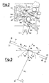
- the movable contact arm 20 would tend to return to its closure position, then it would be restrained by the engagement of the pin 21 and tooth 156, as it is clearly shown by its position 21 ⁇ in figure 2.
- the movable contact arm 20 would be accordingly stopped at the position 20 ⁇ shown in said figure.
- the supporting member 40 will be brought to the open position by means of a clockwise rotation.
- said latching mechanism can be, either also or alternatively, provided to the movable contact arm 26.
- An exemplary electromagnetic actuator 80 is shown inside an insulating box or casing 82, being provided with an extension conductor or wire 84 for the fixed contact arm 14 possibly coupled to a clamp 86.
- Said box or casing 82 is coupled to an assembly of modular units 10 both by means of the metal extention 84 and by means of mechanical coupling means (not shown).
- Said casing 82 also contains an actuating electromagnet 90 which is affixed to a base 92 in turn structurally coupled to the casing 82 and comprising an energizing winding 94, on a fixed core 96, a movable armature 98 and a return spring 100 so arranged as to operate by compression between the base 92 and a bracket member 102 affixed to said movable armature 98.
- a pin 104 extends which entrains a lever 106 pivoted at one end thereof about a pin 108 affixed to said insulating casing 82.
- the other end of said lever 106 supports a second pin 109 engaging a slot 110 of a lug 112 pertainting to a bracket member 114 able of rotating about the pivot pin 38 so as to push the movable contact arms 20 and 26 by means of entraining or driving projections 116 and 118 respectively.
- Said pin 104 also entrains or drives a first end of a driving rod 120 having the other end thereof traversed by a pin 122 engaging one end of a first arm of a crank lever 124 pivoted on a pin 126 affixed to the insulating casing 82.
- crank lever 124 supports an indicating flag 128 facing a window 130 of the casing 82 in order to show the energized condition of said electromagnet 90 and accordingly the opening or closing condition of the contact arrangement.
- the electromagnetic actuator 80 can be added to or removed from the modular units 10 without practically preventing their operation.
- Said electromagnetic actuator 80 will open the contact pairs 18, 22 and 28, 32 when the breaker operating or driving rod 44 is in its closure position (as shown in figure 1) and the electromagnet 90 is de-energized, thereby the spring 100 will move the movable armature 98 away from the fixed core 96 and then, through the bracket 102, the lever 106 and the lug 112, the bracket rotating member 114 will be counterclockwise turned, said bracket rotating member 114 entraining to open the movable contact arms 20 and 26 respectively.
- the rotation center 42 of the rotating supporting element 40 does not coincide with the pivot pin 38, on which are pivoted the movable contact arms 20 and 26, and moreover said center is also offset from the normal symmetry axis passing through the rotation center of said arms, thereby said pivot pin 38 will perform, with respect to said rotation center 42, a movement which will have on the movable contact arms 20 and 26 and on the contacts 22 and 28 associated therewith the effects which are shown in figure 3 and which will be disclosed in a detailed way hereinafter.
- this force can be thought as consisting of the vectorial sum of a component F 2T tangent to said line of the movable contact arms 20 and 26 and a component F 2N perpendicular to the mentioned line.
- the component F 2T will transmit to the movable contact arms 20 and 26 a stress parallel to said arms, which will cause the fixed contacts 18 and 32 and movable contacts 22 and 28 to mutually rub against one another, while the normal or perpendicular component F 2N , which is applied to the pivot pin 38, which is a hinge pin for hinge coupling the two movable contact arms 20 and 26, will urge toward the pin 42 the hinged ends of the movable contact arms which will tend to rotate their movable contacts, respectively 22 and 28, on the corresponding fixed contacts 18 and 32.
- the contact arms will be held in their closing condition as far as the rotating supporting element 40 is held in its position of figure 1 and the current passing through said contacts and the arms thereof is within the rated values.
- the contact arm 20 Under the urging of the spring 32, the contact arm 20 will be then brought to the latching position defined by its pin 21 abutting against the tooth 156 of the latching mechanism, clearly shown in figure 2, said latching being released as the breaker tripping members operate which, by causing the supporting element to move to the opening position, will engage the lug or tailpiece 158 of the latching element against the shaped projection 164 which will rotate clockwise the lever 150 thereby disengaging the tooth 156 from the pin 21 and also disengaging the movable contact arm 20.
- the latching operation is necessary in order to prevent the contact from closing by bouncing under the effect of the great electrodynamic forces, before its opening under the control of the associated overcurrent tripping or releasing members.
- the breaker is used in association with the electromagnetic actuator 80, then it is not sure that, by bringding the rotating element 40 to the position shown in figure 1, the movable contact arms 20 and 26 are brought to their closing position, because it depends from the fact that the rotaing bracket member 114 must be arranged at the position shown in figure 1, which position can be obtained exclusively as the electromagnet 90 of the electromagnetic actuator is energized, that is with its armature 98 abutting against its fixed core 96 since, if the electromagnet 90 were de-energized, then the armature 98 would be moved away from its fixed core 96, under the bias of the return spring 100, thereby causing the rotating bracket member 114 to oppose by its projections 116, 118, through the bracket 102, pin 104, lever 106 with its first end 109 and lug 112, to the closing displacement of the movable contact arms which, by overcoming the forces of their springs 52 and 56, would be brought to the opening position.
- the contact of the modular unit 10 can be closed only if the manual driving rod 44 is in its closure position and the electromagnet 90 of the electromagnetic actuator 80 is energized.
- the movable contact arms 20 and 26 can be brought to the closing position depending on whether electromagnet 90 is de-energized or energized. In this case the apparatus will operate as an actuating apparatus driven by an electromagnet.
Abstract
Description
- The present invention is an improvement of the invention disclosed and claimed in EP-
A-01 72 488 filed on 06.08.1985. In the mentioned publication there are disclosed several contact arrangements of the free repulsion type, arranged, as modular units, within single-pole boxes and adapted to be driven both manually and by electromagnetic actuators, said arrangements consisting of two fixed contact arms, on which abut two movable contact arms connected to one another by means of a flexible conductor braid and adapted to be turned in mutually opposite directions by means of two supporting members operated by two driving rods coupled to a push rod which can be operated by separate driving means. - The above disclosed contact arrangements operate in a satisfactory manner: however, because of the rotation in mutually opposite directions of the movable contact arms, entrained by said supporting member, the flewible conductor braid connecting said arms is greatly stressed, as it is greatly bent, thereby decreasing it's operating life.
- Moreover, since each movable contact arm is provided with a respective supporting member, the mechanism driving said arms is of very complex construction with a consequent high cost.
- Another drawback is that, since two supporting members are used for two movable contact arms, a driving mechanism with an electromagnetic actuator affecting a single movable arm must be used. In fact a driving mechanism able of simultaneously operating both said movable arms would be very complex and expensive.
- From the prior art is known EP-A-0237607 disclosing, in the embodiment depicted in figures 5 to 8, an electric interrupting device, of the kind of relays or contactors, in which the closure of the
contacts 34 is provided by the energization of an electromagnet 13, further provided with first manual tripping means or push button 7 to disengage the contact bearing member 39 of the relay from the armature 19 thereof and with second manual resetting means 49 to re-engage the contact bearing member 39 with the armature 19 after any kind of trip intervention, which can be either automatic, through the thermal trip unit 9 or the magnetic trip unit 35, or manual through the push button 7. About the above mentioned prior art there is to observe that, apart a complete different mechanical structure of its contact arms, the there disclosed relay always needs the operation of the electromagnet 13, being completely unable to operate a closure of thecontacts 34 without the presence and the action of the electromagnet 13. It means that the arrangement according to the above publication cannot be used to close thecontacts 34, as a simple hand actuated circuit breaker, while the circuit breaker according to the present invention can do that. Further being the movements of thecontacts 34 substantially linear, it is impossible to enjoy all the benefical features connected with the rotational movement of the contact arms and the reciprocal rubbing action among each other faced contacts of the present invention. - Accordingly, a main object of the present invention is to provide a contact arrangement which is more simple than that of the mentioned publication while providing like electric performance.
- Another object is to provide an improved contact arrangement, adapted to be actuated both manually and by an electromagnetic actuator in which the two actuations affect both the movable contact arms.
- Another object is to provide an improved contact arrangement in which the manual actuation is performed by bringing closer and moving away contacts, with an associated displacement of said contacts able of causing said contacts to rub one against the other in order to remove possible oxide films thereby providing a small contact resistance or removing possible microweldings.
- Still another object is to provide a contact arrangement all of the component elements of which can be assembled by a single direction displacement and in which the contact elements can be coupled both to the manual driving mechanism and to the electromagnetic actuator by means of simple translation movements.
- According to one aspect of the present invention, the above mentioned objects, as well as yet other objects which will become more apparent hereinafter, are achieved by an improved contact arrangement for a current limiting breaker, of the free repulsion type, consisting of a modular unit to be housed in a usually insulating box or compartment, comprising two fixed contact arms provided with contacts, two movable contact arms provided with contacts and being driven both manually, by a single rod coupled to driving means, and electrically by a single electromagnetic actuator, characterized in that said movable contact arms are pivoted on a single pivot pin arranged at the ends of said movable arms opposite to the ends thereof supporting the contacts, so as to cause said movable arms to rotate in the same angular direction, said single pivot pin being supported by a single rotatable member which can be driven by said rod for manual actuations, said electromagnetic actuator controlling a rotating bracket member which causes said movable contact arms to be brought to their open condition as an electromagnet of said electromagnetic actuator is de-energized, and in that the movements of the rotatable member and the rotating bracket member are mutually independent.
- More specifically said movable contact arms are electrically coupled to one another by means of a flexible braided conductor and one of said arms is provided with a detent member for preventing said movable contact arms from being disaligned beyond a given limit.
- In particular, at least one of said movable contact arms is provided with a pin or peg adapted to be engaged by a latching mechanism which can be disengaged by rotating said rotating member.
- The latching or engaging mechanism consists of a lever including a fulcrum fixed to said rotating member, having a first end provided with a sliding surface and a latching tooth, and a second end or tail abutting against a spring in turn abutting against a ridge of said rotating member and the stroke of which is restrained by a shaped projection, rigid with the supporting structure of said modular unit, so as to latch said at least one of said movable contact arms after an opening due to an electrodynamic repulsion caused by a short circuit current so as to prevent said at least one arm from being suddenly closed against one of its detent members and then to disengage said at least one arm by causing said second end or tail to engage against said shaped projection as the rotating member is brought to its open position by external tripping members or as the breaker is manually reset.
- In further details, said contact arrangement, in which the movable contact arms are pivoted on a pin fixed to said rotating element is characterized in that said pin does not coincide with a rotation center about which the rotating element driven by said rod turns as the breaker is manually operated, in order to be displaced on a circle arc to provide a tangential or rubbing movement of the movable contacts on the fixed contacts.
- The pivot pin of said movable contact arms is eccentrical with respect to the rotation center of the rotating element and moreover it is offset from the contact normal symmetry axis passing through the rotation center of said contacts coinciding with said pin, so as to cause said pin to be displaced as the breaker is manually operated, on a circle arc which is not tangent to a longitudinal axis of said movable contact arms passing through their rotation center in order to provide, in addition to the mentioned rubbing movement, also a rotating movement of said movable contacts on said fixed contacts, in order to lessen the contact bounce and subject the contacts to a twisting moment suitable to remove possible welded areas formed between said contacts.
- The rotating member is provided with a lug including an open slot engaged by a pin supported by said rod coupled to manual driving means and with two first projections restraining two springs adapted to push said movable contact arms to their closure position.
- The rotating member is moreover provided with two projections suitable to entrain said movable contact arms to their opening position.
- Said rotating bracket member is preferably engaged on the single pin of the two movable contact arms and is provided with projections suitable to be engaged with the movable contact arms to displace them to the opening position as the electromagnet of said electromagnetic actuator is de-energized.
- Said rotating bracket member is further provided with a lug to engage, by an open slot formed therethrough, a pin supported by a lever which is driven or controlled by said electromagnet of said electromagnetic actuator.
- Said electromagnet further controls, through a tie rod, a cranck lever provided with an indicating flag facing a window of a box holding said electromagnetic actuator.
- Further features and advantages of the present invention will become more apparent hereinafter from the following detailed description of a preferred embodiment thereof, with reference to the accompanying drawings, in which :
- figure 1 shows the contact arrangement according to the present invention including a driving electromagnet;
- figure 2 shows a detail of a latching mechanism of a movable contact arm which operates as hereinbelow disclosed;
- figure 3 schematically shows the vectors of the forces originally applied to the arms of the contacts during the manual opening operation, which are very useful since they provide a rubbing action on the contacts and are able of detaching them, if welded by possible overcurrents, and correspondingly shows those same forces as reversed during the manual closing operation, which reversed forces cause the cooperating conatct members to mutually rub and roll.
- With reference to figure 1 which shows a
modular unit 10 holding a contact arrangement according to the present invention, housed in abreaker casing 12, said contact arrangement consists or a first fixedcontact arm 14 which bears, at a first end thereof, aclamp 16 and, at the second end thereof, acontact 18; of a firstmovable contact arm 20, bearing acontact 22; of a flexiblebraided conductor 24 coupled to themovable arm 20; a secondmovable contact arm 26, also coupled to theflexible conductor 24 and bearing acontact 28; a second fixedcontact 30 bearing acontact 32; and anoutput coupling conductor 34 coupled by ascrew 36 to said fixedcontact arm 30. - The two
movable contact arms pivot pin 38 affixed to a supporting element ormember 40 which, in turn, can rotate about apin 42 rigidly affixed with respect to theunit 10 supporting structure. Moreover thecontact arm 26 is provided with a projection or fin 27 adapted to prevent the twomovable arms movable contact arm 20. - Said supporting
member 40 is pushed to the position shown in figure 1 by means of arod 44 which operates through apin 46 coupled to saidrod 44 within aslot 48 formed through alug 50 of said supporting rotatingmember 40. Saidrod 44 is obviously coupled to the breaker operating or actuating means (not shown). - The
movable contact arm 20 is held in the position of figure 1 by means of aspring 52 operating between aprojection 54, also provided on the supportingmember 40, and the samemovable arm 20. Likewise, themovable contact arm 26 is held in the same position of figure 1 by means of aspring 56 operating between aprojection 58, also provided on the supportingmember 40, and saidmovable arm 26. - Said rotating
member 40 is also provided with twoprojections member 40 is counterclockwise rotated, will entrain to the open position themovable contact arms - Two
projections unit 10 supporting structure operate as detent members for the respectivemovable contact arms positions 20′ and 26′. - The assembly consisting of the fixed
contact arm 14 andmovable contact arm 20 is arranged in front of anarc chute 64 provided withquenching plates 66. The assembly consisting of the fixedcontact arm 30 andmovable contact arm 26 is arranged in front of anarc chute 68 provided withquenching plates 70. - The
modular unit 10 can also comprise driving and unlatching mechanisms so as to form a single pole breaker, or severalmodular units 10 can be assembled in an insulating box orcasing 12 also holding driving and unlatching mechanisms so as to form a multipole breaker. - Moreover, at least one of the movable contact arms, for example the
arm 20, can be provided with a latching mechanism consisting of alever 150 rotatable about thefulcrum 152 having a first end provided with a slidingsurface 154 and alatching tooth 156 and a second end, lug ortail 158 abutting against aspring 160 which, in turn, abuts against aprojection 162 supported by said rotatingelement 40 and the stroke of which is restrained by a shaped step orridge 164 rigid with saidunit 10 supporting structure. Said latching mechanism operates so as to prevent themovable contact 22 from reclosing against the fixed contact because of a bouncing of themovable contact arm 20 against itsdetent projection 72. - The unlatching mechanism operates as follows: as because of a short circuit current, the
movable contact arm 20 is moved away, by electrodynamic repulsion, from the fixedcontact arm 14, by counterclockwise rotating about itspivot pin 38, a peg orpin 21 arranged on saidarm 20 slides on thesurface 154 of thelever 150 so as to pass beyond or clear the latching tooth, thereby thelever 150 will rotate as biased by itsspring 160 and will be held in abutment against thepin 21. If, because of a bounce against theprojection 72 or a decreasing of the short circuit current, themovable contact arm 20, as urged by itsspring 52, would tend to return to its closure position, then it would be restrained by the engagement of thepin 21 andtooth 156, as it is clearly shown by itsposition 21˝ in figure 2. Themovable contact arm 20 would be accordingly stopped at theposition 20˝ shown in said figure. - Then, as the tripping members operate, the supporting
member 40 will be brought to the open position by means of a clockwise rotation. - With this rotation, the lug or
tail 158 of the latching member will rub on the suitably shaped upturned portion orprojection 164, thereby said latching member will rotate so as to disengage thepin 21 of themovable contact arm 20 which will be able of abutting against itsnatural detent 60. - In this connection it should be apparent that said latching mechanism can be, either also or alternatively, provided to the
movable contact arm 26. An exemplary electromagnetic actuator 80 is shown inside an insulating box orcasing 82, being provided with an extension conductor orwire 84 for the fixedcontact arm 14 possibly coupled to aclamp 86. Said box orcasing 82 is coupled to an assembly ofmodular units 10 both by means of themetal extention 84 and by means of mechanical coupling means (not shown). Saidcasing 82 also contains anactuating electromagnet 90 which is affixed to abase 92 in turn structurally coupled to thecasing 82 and comprising anenergizing winding 94, on a fixedcore 96, amovable armature 98 and areturn spring 100 so arranged as to operate by compression between thebase 92 and abracket member 102 affixed to saidmovable armature 98. Through the bracket 102 apin 104 extends which entrains alever 106 pivoted at one end thereof about apin 108 affixed to said insulatingcasing 82. The other end of saidlever 106 supports asecond pin 109 engaging aslot 110 of alug 112 pertainting to abracket member 114 able of rotating about thepivot pin 38 so as to push themovable contact arms driving projections - Said
pin 104 also entrains or drives a first end of adriving rod 120 having the other end thereof traversed by apin 122 engaging one end of a first arm of acrank lever 124 pivoted on apin 126 affixed to the insulatingcasing 82. - The other arm of said
crank lever 124 supports an indicatingflag 128 facing awindow 130 of thecasing 82 in order to show the energized condition of saidelectromagnet 90 and accordingly the opening or closing condition of the contact arrangement. - As is clearly shown in figure 1, the electromagnetic actuator 80 can be added to or removed from the
modular units 10 without practically preventing their operation. - Said electromagnetic actuator 80 will open the
contact pairs rod 44 is in its closure position (as shown in figure 1) and theelectromagnet 90 is de-energized, thereby thespring 100 will move themovable armature 98 away from the fixedcore 96 and then, through thebracket 102, thelever 106 and thelug 112, thebracket rotating member 114 will be counterclockwise turned, saidbracket rotating member 114 entraining to open themovable contact arms - As shown in figure 1, the
rotation center 42 of the rotating supportingelement 40 does not coincide with thepivot pin 38, on which are pivoted themovable contact arms pivot pin 38 will perform, with respect to saidrotation center 42, a movement which will have on themovable contact arms contacts - With reference to figure 3, it should be apparent that the assembly consisting of the rotating supporting
member 40 and fixed andmovable contact arms member 40 is diagramatically illustrated as consisting of the two arms R₁ and R₂, while the contact arms are represented schematically by straight line segments having the same reference numbers as the corresponding contact arms, in this figure there being also shown the points representing the respective rotation pins orcenters - As a force F₁ is applied to the
pin 46 arranged at one end of the arm R₁, this force, owing to thepin 42 operating as a fulcrum, will be transformed into a force F₂ applied to thepivot pin 38, said force F₂ having a direction tangent to a circle C centered on thefulcrum 42 and passing throhgh thepivot pin 38. - Since the lines representing the two
movable contact arms movable contact arms - The component F2T will transmit to the
movable contact arms 20 and 26 a stress parallel to said arms, which will cause thefixed contacts movable contacts pivot pin 38, which is a hinge pin for hinge coupling the twomovable contact arms pin 42 the hinged ends of the movable contact arms which will tend to rotate their movable contacts, respectively 22 and 28, on the correspondingfixed contacts movable contacts fixed contacts - On the contrary, during the closure operation, F₂, F2T and F2N will become F′₂, F′2T and F′2N which, by generating reversed rubbings with respect to the opening rubbigs, will surface clean the contacts and lessen their bounces.
- If the breaker is used without the electromagnetic actuator 80, then the contact arms will be held in their closing condition as far as the rotating supporting
element 40 is held in its position of figure 1 and the current passing through said contacts and the arms thereof is within the rated values. - If a short circuit condition occurs, then the current would be raised to such a value as to cause an electrodynamic repulsion between the respective contact arm pairs 14, 20 and 30, 26, thereby the
movable contact arms respective springs - Under the urging of the
spring 32, thecontact arm 20 will be then brought to the latching position defined by itspin 21 abutting against thetooth 156 of the latching mechanism, clearly shown in figure 2, said latching being released as the breaker tripping members operate which, by causing the supporting element to move to the opening position, will engage the lug ortailpiece 158 of the latching element against the shapedprojection 164 which will rotate clockwise thelever 150 thereby disengaging thetooth 156 from thepin 21 and also disengaging themovable contact arm 20. - As previously discussed, the latching operation is necessary in order to prevent the contact from closing by bouncing under the effect of the great electrodynamic forces, before its opening under the control of the associated overcurrent tripping or releasing members.
- If, on the contrary, the breaker is used in association with the electromagnetic actuator 80, then it is not sure that, by bringding the
rotating element 40 to the position shown in figure 1, themovable contact arms rotaing bracket member 114 must be arranged at the position shown in figure 1, which position can be obtained exclusively as theelectromagnet 90 of the electromagnetic actuator is energized, that is with itsarmature 98 abutting against its fixedcore 96 since, if theelectromagnet 90 were de-energized, then thearmature 98 would be moved away from its fixedcore 96, under the bias of thereturn spring 100, thereby causing the rotatingbracket member 114 to oppose by itsprojections bracket 102,pin 104,lever 106 with itsfirst end 109 and lug 112, to the closing displacement of the movable contact arms which, by overcoming the forces of theirsprings - Thus, the contact of the
modular unit 10 can be closed only if themanual driving rod 44 is in its closure position and theelectromagnet 90 of the electromagnetic actuator 80 is energized. - Likewise, as the breaker is closed and the supporting
element 40 is in the position shown in figure 1, themovable contact arms electromagnet 90 is de-energized or energized. In this case the apparatus will operate as an actuating apparatus driven by an electromagnet. - While the invention as been disclosed and illustrated with reference to a preferred embodiment thereof it should be apparent that the disclosed embodiment is susceptible to several modifications and variations all of which will come within the scope of the appended claims.
Claims (11)
- A contact arrangement for a current limiting circuit breaker, of the free repulsion kind, consisting of a modular unit to be housed in a usually insulating box or compartment (12), comprising two fixed contact arms (14, 30) provided with contacts (18, 32), two movable contact arms (20, 26) provided with contacts (22, 28) and being driven both manually by a single rod (44) coupled to manual driving means and electrically by a single electromagnetic actuator (80) characterized in that said movable contact arms (20, 26) are pivoted on a single pivot pin (38) arranged at the ends thereof supporting the contacts (22, 28), so as to cause said movable arms (20, 26) in the same angular direction, said single pivot pin (38) being supported by a single rotatable member (40) which can be driven by said rod (44) for the manual actuation, said electromagnetic actuator (80) controlling a rotating bracket member (114) which causes said movable contact arms (20, 26) to be brought to their open position as an electromagnet (90) of said electromagnetic actuator (80) is de-energized, and in that the movements of the rotatable member (40) and of the rotating bracket member (114) are mutually independent.
- A contact arrangement, according to claim 1, characterized in that said movable contact arms (20, 26) are electrically connected to one another by means of a flexible braided conductor (24) and one of said arms is provided with a detent member (27) for preventing said movable contact arms (20, 26) from being disaligned beyond a given limit.
- A contact arrangement according to claim 2, characterized in that at least one of said movable arms (20, 26) is provided with a pin or peg (21) adapted to be engaged by a latching mechanism which can be disengaged by rotating said rotatable member (40).
- A contact arrangement according to claim 3, characterized in that said latching mechanism consists of a lever (150) including a fulcrum (152) fixed to said rotatable member (40), having a first end provided with a sliding surface (154) and a latching tooth (156), and a second end or tail (158) abutting against a spring (160) in turn abutting against a ridge (162) of said rotatable member (40) and the stroke of which is restrained by a shaped projection (164) rigid with the supporting structure of said modular unit so as to latch said at least one of said movable contact arms after an opening due to an electrodynamic repulsion caused by a short circuit current so as to prevent said at least one arm from being suddenly closed against one of its detent members (72, 74) and then to disegage said at least one arm by causing said second end or tail (158) to engage against said shaped projection (164) as said rotatable member (40) is brought to its open position by external tripping members or as the breaker is manually reset.
- A contact arrangement according to claims 1 to 4, wherein the movable contact arms (20, 26) are pivoted on a pivot pin (38) fixed to said rotatable member (40), characterized in that said pivot pin (38) does not coincide with a rotation center (42), about which said rotatable member (40), driven by said rod (44), turns, as the breaker is manually operated in order to be displaced on a circle arc to provide a tangential or rubbing movement of the movable contacts (22, 28) on the fixed contacts (18, 32).
- A contact arrangement, according to claim 5, characterized in that said pivot pin (38), about which said movable contact arms (20, 26) turn, is eccentrical with respect to said rotation center (42) of said rotatable member (40) and moreover said pivot pin is offset from the normal symmetry axis passing through the rotation center of said contacts coinciding with said pivot pin (38), so as to cause said pivot pin (38) to be displaced, as the breaker in manually operated, on a circle arc which in not tangent to a longitudinal axis of said movable contact arms (20, 26) passing through their rotation center in order to provide, in addition to said rubbing movement, also a rotating movement of said movable contacts (22, 28) on said fixed contacts (18, 32), in order to lessen the contact bounce and submit the contacts to a twisting moment suitable to remove possible welded areas formed between said contacts.
- A contact arrangement, according to claim 1, characterized in that said rotatable member (40) is provided with a lug (50) including an open slot (48) engaged by a pin (46) supported by said rod (44) coupled to manual driving means and with two first projections (54, 58) restrainig two springs (52, 56) suitable to push said movable contact arms (20, 26) to their closure position.
- A contact arrangement, according to claim 7, characterized in that said rotatable member (40) is provided with two projections (60, 62) suitable to displace said movable contact arms (20, 26) to their opening position.
- A contact arrangement according to claim 7, characterized in that said rotating bracket member (114) is pivoted on the single pivot pin (30) of the two movable contact arms (20, 26) and is provided with projections (116, 118) suitable to be engaged with the movable contact arms (20, 26) to displace them to the opening position as the electromagnet (90) of said electromagnetic actuator (80) is de-energized.
- A contact arrangement according to claim 9, characterized in that said rotating bracket member (114) is further provided with a lug (112) to engage, by an cpen slot (110) formed therethrough, a pin (109) supported by a lever (106) which is driven by said electromagnet (90) of said electomagnect actuator (80).
- A contact arrangement according to claim 10, characterized in that said electromagnet (90) further controls, through a tie rod (120), a crank lever (124) provided with an indicating flag (128) facing a window (130) of a box (82) holding said electromagnetic actuator (80).
Applications Claiming Priority (3)
| Application Number | Priority Date | Filing Date | Title |
|---|---|---|---|
| IT2210787 | 1987-10-01 | ||
| IT22107/87A IT1222801B (en) | 1987-10-01 | 1987-10-01 | Solenoid and manually actuated free repulsion circuit breaker |
| US07/251,492 US4916421A (en) | 1987-10-01 | 1988-09-30 | Contact arrangement for a current limiting circuit breaker |
Publications (3)
| Publication Number | Publication Date |
|---|---|
| EP0309923A2 EP0309923A2 (en) | 1989-04-05 |
| EP0309923A3 EP0309923A3 (en) | 1990-06-13 |
| EP0309923B1 true EP0309923B1 (en) | 1994-12-14 |
Family
ID=26328099
Family Applications (1)
| Application Number | Title | Priority Date | Filing Date |
|---|---|---|---|
| EP88115601A Expired - Lifetime EP0309923B1 (en) | 1987-10-01 | 1988-09-22 | Improved contact arrangement for a current limiting circuit breaker adapted to be actuated both manually and by an actuating electromagnet |
Country Status (5)
| Country | Link |
|---|---|
| US (1) | US4916421A (en) |
| EP (1) | EP0309923B1 (en) |
| JP (1) | JPH01117228A (en) |
| AT (1) | ATE115768T1 (en) |
| DE (1) | DE3852455T2 (en) |
Cited By (68)
| Publication number | Priority date | Publication date | Assignee | Title |
|---|---|---|---|---|
| US6037555A (en) | 1999-01-05 | 2000-03-14 | General Electric Company | Rotary contact circuit breaker venting arrangement including current transformer |
| US6087913A (en) | 1998-11-20 | 2000-07-11 | General Electric Company | Circuit breaker mechanism for a rotary contact system |
| US6114641A (en) | 1998-05-29 | 2000-09-05 | General Electric Company | Rotary contact assembly for high ampere-rated circuit breakers |
| US6166344A (en) | 1999-03-23 | 2000-12-26 | General Electric Company | Circuit breaker handle block |
| US6172584B1 (en) | 1999-12-20 | 2001-01-09 | General Electric Company | Circuit breaker accessory reset system |
| US6175288B1 (en) | 1999-08-27 | 2001-01-16 | General Electric Company | Supplemental trip unit for rotary circuit interrupters |
| US6184761B1 (en) | 1999-12-20 | 2001-02-06 | General Electric Company | Circuit breaker rotary contact arrangement |
| US6188036B1 (en) | 1999-08-03 | 2001-02-13 | General Electric Company | Bottom vented circuit breaker capable of top down assembly onto equipment |
| US6204743B1 (en) | 2000-02-29 | 2001-03-20 | General Electric Company | Dual connector strap for a rotary contact circuit breaker |
| US6211758B1 (en) | 2000-01-11 | 2001-04-03 | General Electric Company | Circuit breaker accessory gap control mechanism |
| US6211757B1 (en) | 2000-03-06 | 2001-04-03 | General Electric Company | Fast acting high force trip actuator |
| US6215379B1 (en) | 1999-12-23 | 2001-04-10 | General Electric Company | Shunt for indirectly heated bimetallic strip |
| US6218917B1 (en) | 1999-07-02 | 2001-04-17 | General Electric Company | Method and arrangement for calibration of circuit breaker thermal trip unit |
| US6218919B1 (en) | 2000-03-15 | 2001-04-17 | General Electric Company | Circuit breaker latch mechanism with decreased trip time |
| US6225881B1 (en) | 1998-04-29 | 2001-05-01 | General Electric Company | Thermal magnetic circuit breaker |
| US6232859B1 (en) | 2000-03-15 | 2001-05-15 | General Electric Company | Auxiliary switch mounting configuration for use in a molded case circuit breaker |
| US6232570B1 (en) | 1999-09-16 | 2001-05-15 | General Electric Company | Arcing contact arrangement |
| US6232856B1 (en) | 1999-11-02 | 2001-05-15 | General Electric Company | Magnetic shunt assembly |
| US6239398B1 (en) | 2000-02-24 | 2001-05-29 | General Electric Company | Cassette assembly with rejection features |
| US6239677B1 (en) | 2000-02-10 | 2001-05-29 | General Electric Company | Circuit breaker thermal magnetic trip unit |
| US6239395B1 (en) | 1999-10-14 | 2001-05-29 | General Electric Company | Auxiliary position switch assembly for a circuit breaker |
| US6252365B1 (en) | 1999-08-17 | 2001-06-26 | General Electric Company | Breaker/starter with auto-configurable trip unit |
| US6262872B1 (en) | 1999-06-03 | 2001-07-17 | General Electric Company | Electronic trip unit with user-adjustable sensitivity to current spikes |
| US6262642B1 (en) | 1999-11-03 | 2001-07-17 | General Electric Company | Circuit breaker rotary contact arm arrangement |
| US6268991B1 (en) | 1999-06-25 | 2001-07-31 | General Electric Company | Method and arrangement for customizing electronic circuit interrupters |
| US6281461B1 (en) | 1999-12-27 | 2001-08-28 | General Electric Company | Circuit breaker rotor assembly having arc prevention structure |
| US6281458B1 (en) | 2000-02-24 | 2001-08-28 | General Electric Company | Circuit breaker auxiliary magnetic trip unit with pressure sensitive release |
| US6300586B1 (en) | 1999-12-09 | 2001-10-09 | General Electric Company | Arc runner retaining feature |
| US6310307B1 (en) | 1999-12-17 | 2001-10-30 | General Electric Company | Circuit breaker rotary contact arm arrangement |
| US6317018B1 (en) | 1999-10-26 | 2001-11-13 | General Electric Company | Circuit breaker mechanism |
| US6326868B1 (en) | 1997-07-02 | 2001-12-04 | General Electric Company | Rotary contact assembly for high ampere-rated circuit breaker |
| US6326869B1 (en) | 1999-09-23 | 2001-12-04 | General Electric Company | Clapper armature system for a circuit breaker |
| US6340925B1 (en) | 2000-03-01 | 2002-01-22 | General Electric Company | Circuit breaker mechanism tripping cam |
| US6346868B1 (en) | 2000-03-01 | 2002-02-12 | General Electric Company | Circuit interrupter operating mechanism |
| US6346869B1 (en) | 1999-12-28 | 2002-02-12 | General Electric Company | Rating plug for circuit breakers |
| US6362711B1 (en) | 2000-11-10 | 2002-03-26 | General Electric Company | Circuit breaker cover with screw locating feature |
| US6366188B1 (en) | 2000-03-15 | 2002-04-02 | General Electric Company | Accessory and recess identification system for circuit breakers |
| US6373010B1 (en) | 2000-03-17 | 2002-04-16 | General Electric Company | Adjustable energy storage mechanism for a circuit breaker motor operator |
| US6377144B1 (en) | 1999-11-03 | 2002-04-23 | General Electric Company | Molded case circuit breaker base and mid-cover assembly |
| US6380829B1 (en) | 2000-11-21 | 2002-04-30 | General Electric Company | Motor operator interlock and method for circuit breakers |
| US6379196B1 (en) | 2000-03-01 | 2002-04-30 | General Electric Company | Terminal connector for a circuit breaker |
| US6388213B1 (en) | 2000-03-17 | 2002-05-14 | General Electric Company | Locking device for molded case circuit breakers |
| US6396369B1 (en) | 1999-08-27 | 2002-05-28 | General Electric Company | Rotary contact assembly for high ampere-rated circuit breakers |
| US6400245B1 (en) | 2000-10-13 | 2002-06-04 | General Electric Company | Draw out interlock for circuit breakers |
| US6404314B1 (en) | 2000-02-29 | 2002-06-11 | General Electric Company | Adjustable trip solenoid |
| US6429760B1 (en) | 2000-10-19 | 2002-08-06 | General Electric Company | Cross bar for a conductor in a rotary breaker |
| US6429659B1 (en) | 2000-03-09 | 2002-08-06 | General Electric Company | Connection tester for an electronic trip unit |
| US6429759B1 (en) | 2000-02-14 | 2002-08-06 | General Electric Company | Split and angled contacts |
| US6448522B1 (en) | 2001-01-30 | 2002-09-10 | General Electric Company | Compact high speed motor operator for a circuit breaker |
| US6448521B1 (en) | 2000-03-01 | 2002-09-10 | General Electric Company | Blocking apparatus for circuit breaker contact structure |
| US6459059B1 (en) | 2000-03-16 | 2002-10-01 | General Electric Company | Return spring for a circuit interrupter operating mechanism |
| US6459349B1 (en) | 2000-03-06 | 2002-10-01 | General Electric Company | Circuit breaker comprising a current transformer with a partial air gap |
| US6469882B1 (en) | 2001-10-31 | 2002-10-22 | General Electric Company | Current transformer initial condition correction |
| US6472620B2 (en) | 2000-03-17 | 2002-10-29 | Ge Power Controls France Sas | Locking arrangement for circuit breaker draw-out mechanism |
| US6476698B1 (en) | 2000-03-17 | 2002-11-05 | General Electric Company | Convertible locking arrangement on breakers |
| US6476335B2 (en) | 2000-03-17 | 2002-11-05 | General Electric Company | Draw-out mechanism for molded case circuit breakers |
| US6476337B2 (en) | 2001-02-26 | 2002-11-05 | General Electric Company | Auxiliary switch actuation arrangement |
| US6479774B1 (en) | 2000-03-17 | 2002-11-12 | General Electric Company | High energy closing mechanism for circuit breakers |
| US6496347B1 (en) | 2000-03-08 | 2002-12-17 | General Electric Company | System and method for optimization of a circuit breaker mechanism |
| US6531941B1 (en) | 2000-10-19 | 2003-03-11 | General Electric Company | Clip for a conductor in a rotary breaker |
| US6559743B2 (en) | 2000-03-17 | 2003-05-06 | General Electric Company | Stored energy system for breaker operating mechanism |
| US6586693B2 (en) | 2000-03-17 | 2003-07-01 | General Electric Company | Self compensating latch arrangement |
| US6639168B1 (en) | 2000-03-17 | 2003-10-28 | General Electric Company | Energy absorbing contact arm stop |
| US6678135B2 (en) | 2001-09-12 | 2004-01-13 | General Electric Company | Module plug for an electronic trip unit |
| US6710988B1 (en) | 1999-08-17 | 2004-03-23 | General Electric Company | Small-sized industrial rated electric motor starter switch unit |
| US6747535B2 (en) | 2000-03-27 | 2004-06-08 | General Electric Company | Precision location system between actuator accessory and mechanism |
| US6804101B2 (en) | 2001-11-06 | 2004-10-12 | General Electric Company | Digital rating plug for electronic trip unit in circuit breakers |
| US6806800B1 (en) | 2000-10-19 | 2004-10-19 | General Electric Company | Assembly for mounting a motor operator on a circuit breaker |
Families Citing this family (24)
| Publication number | Priority date | Publication date | Assignee | Title |
|---|---|---|---|---|
| JP2895533B2 (en) * | 1989-11-22 | 1999-05-24 | 株式会社東芝 | Circuit breaker |
| SE9002264L (en) * | 1990-06-27 | 1991-12-28 | Asea Brown Boveri | CONTACT DEVICE FOR ELECTRICAL CONNECTORS |
| FR2674370B1 (en) * | 1991-03-21 | 1993-10-29 | Telemecanique | PROTECTIVE SWITCHING APPARATUS ACCOUPABLE TO A CONTROL MODULE AND / OR A SIGNALING MODULE. |
| FR2688625B1 (en) * | 1992-03-13 | 1997-05-09 | Merlin Gerin | CONTACT OF A MOLDED BOX CIRCUIT BREAKER |
| US5319167A (en) * | 1993-03-08 | 1994-06-07 | Eaton Corporation | Electrical contactor employing a rotary disc |
| FR2710453B1 (en) * | 1993-09-24 | 1995-10-20 | Telemecanique | Contactor-circuit breaker device. |
| DE69406334T2 (en) * | 1993-03-25 | 1998-02-26 | Schneider Electric Sa | Switchgear |
| FR2736752B1 (en) * | 1995-07-13 | 1997-08-22 | Schneider Electric Sa | CIRCUIT-BREAKER TYPE SWITCHING APPARATUS |
| DE19630471A1 (en) * | 1996-07-27 | 1998-01-29 | Kloeckner Moeller Gmbh | Switching chamber housing for a circuit breaker and housing modules for producing such a switching chamber housing |
| US6084489A (en) * | 1998-09-08 | 2000-07-04 | General Electric Company | Circuit breaker rotary contact assembly locking system |
| US6229413B1 (en) | 1999-10-19 | 2001-05-08 | General Electric Company | Support of stationary conductors for a circuit breaker |
| US6366438B1 (en) | 2000-03-06 | 2002-04-02 | General Electric Company | Circuit interrupter rotary contact arm |
| US6403909B1 (en) * | 2000-03-13 | 2002-06-11 | General Electric Company | Trip override for rotary breaker |
| US6421217B1 (en) | 2000-03-16 | 2002-07-16 | General Electric Company | Circuit breaker accessory reset system |
| US6373357B1 (en) | 2000-05-16 | 2002-04-16 | General Electric Company | Pressure sensitive trip mechanism for a rotary breaker |
| US6995640B2 (en) * | 2000-05-16 | 2006-02-07 | General Electric Company | Pressure sensitive trip mechanism for circuit breakers |
| KR100373441B1 (en) * | 2001-02-20 | 2003-02-25 | 현대중공업 주식회사 | Twin Repulsive Moving Breaking Contact Unit Of Molded Case Circuit Breaker |
| US6882258B2 (en) * | 2001-02-27 | 2005-04-19 | General Electric Company | Mechanical bell alarm assembly for a circuit breaker |
| JP4356267B2 (en) * | 2001-05-28 | 2009-11-04 | 富士電機機器制御株式会社 | Circuit breaker for wiring |
| JP3997818B2 (en) * | 2001-05-28 | 2007-10-24 | 富士電機機器制御株式会社 | Circuit breaker for wiring |
| JP4147344B2 (en) * | 2002-08-13 | 2008-09-10 | 富士電機機器制御株式会社 | Circuit breaker |
| US7911302B2 (en) * | 2007-11-15 | 2011-03-22 | General Electric Company | Secondary trip system for circuit breaker |
| JP5018844B2 (en) * | 2009-08-20 | 2012-09-05 | 富士電機機器制御株式会社 | Magnetic contactor |
| CN108987138B (en) * | 2017-06-01 | 2024-02-02 | 泰科电子(深圳)有限公司 | Electrical contact system |
Family Cites Families (9)
| Publication number | Priority date | Publication date | Assignee | Title |
|---|---|---|---|---|
| CH223145A (en) * | 1941-12-16 | 1942-08-31 | Landis & Gyr Ag | Auto switch. |
| US3533027A (en) * | 1967-12-29 | 1970-10-06 | Terasaki Denki Sangyo Kk | Contact assembly of circuit interrupter |
| DE1638042A1 (en) * | 1968-03-08 | 1971-07-01 | Hundt & Weber | Circuit breaker with automatic instantaneous maximum current disconnection |
| FR2373143A1 (en) * | 1976-12-06 | 1978-06-30 | Telemecanique Electrique | Electromagnetic switch with- two symmetrically pivoted arms - has arms integral with armature with spring transverse to movement of support |
| EP0059475B1 (en) * | 1981-03-02 | 1986-06-25 | Mitsubishi Denki Kabushiki Kaisha | A current limiter |
| FR2503929A1 (en) * | 1981-04-13 | 1982-10-15 | Kruglyansky Igor | AUTOMATIC LOAD INTERRUPTION PROCESS AND AUTOMATIC LOAD INTERRUPTER FOR CARRYING OUT SAID METHOD |
| IT1175633B (en) * | 1984-08-14 | 1987-07-15 | Cge Spa | Contact arrangement for current limiting circuit breaker |
| DE3431288A1 (en) * | 1984-08-23 | 1986-03-06 | Siemens AG, 1000 Berlin und 8000 München | CONTACT ARRANGEMENT FOR LOW VOLTAGE CIRCUIT BREAKERS WITH A TWO-ARM CONTACT LEVER |
| EP0237607A1 (en) * | 1986-03-21 | 1987-09-23 | Square D Company (Deutschland) Gmbh | Contactor |
-
1988
- 1988-09-22 EP EP88115601A patent/EP0309923B1/en not_active Expired - Lifetime
- 1988-09-22 AT AT88115601T patent/ATE115768T1/en not_active IP Right Cessation
- 1988-09-22 DE DE3852455T patent/DE3852455T2/en not_active Expired - Fee Related
- 1988-09-30 US US07/251,492 patent/US4916421A/en not_active Expired - Fee Related
- 1988-09-30 JP JP63244708A patent/JPH01117228A/en active Pending
Cited By (76)
| Publication number | Priority date | Publication date | Assignee | Title |
|---|---|---|---|---|
| US6326868B1 (en) | 1997-07-02 | 2001-12-04 | General Electric Company | Rotary contact assembly for high ampere-rated circuit breaker |
| US6225881B1 (en) | 1998-04-29 | 2001-05-01 | General Electric Company | Thermal magnetic circuit breaker |
| US6259048B1 (en) | 1998-05-29 | 2001-07-10 | General Electric Company | Rotary contact assembly for high ampere-rated circuit breakers |
| US6114641A (en) | 1998-05-29 | 2000-09-05 | General Electric Company | Rotary contact assembly for high ampere-rated circuit breakers |
| US6087913A (en) | 1998-11-20 | 2000-07-11 | General Electric Company | Circuit breaker mechanism for a rotary contact system |
| US6037555A (en) | 1999-01-05 | 2000-03-14 | General Electric Company | Rotary contact circuit breaker venting arrangement including current transformer |
| US6166344A (en) | 1999-03-23 | 2000-12-26 | General Electric Company | Circuit breaker handle block |
| US6400543B2 (en) | 1999-06-03 | 2002-06-04 | General Electric Company | Electronic trip unit with user-adjustable sensitivity to current spikes |
| US6262872B1 (en) | 1999-06-03 | 2001-07-17 | General Electric Company | Electronic trip unit with user-adjustable sensitivity to current spikes |
| US6268991B1 (en) | 1999-06-25 | 2001-07-31 | General Electric Company | Method and arrangement for customizing electronic circuit interrupters |
| US6218917B1 (en) | 1999-07-02 | 2001-04-17 | General Electric Company | Method and arrangement for calibration of circuit breaker thermal trip unit |
| US6188036B1 (en) | 1999-08-03 | 2001-02-13 | General Electric Company | Bottom vented circuit breaker capable of top down assembly onto equipment |
| US6252365B1 (en) | 1999-08-17 | 2001-06-26 | General Electric Company | Breaker/starter with auto-configurable trip unit |
| US6710988B1 (en) | 1999-08-17 | 2004-03-23 | General Electric Company | Small-sized industrial rated electric motor starter switch unit |
| US6175288B1 (en) | 1999-08-27 | 2001-01-16 | General Electric Company | Supplemental trip unit for rotary circuit interrupters |
| US6396369B1 (en) | 1999-08-27 | 2002-05-28 | General Electric Company | Rotary contact assembly for high ampere-rated circuit breakers |
| US6232570B1 (en) | 1999-09-16 | 2001-05-15 | General Electric Company | Arcing contact arrangement |
| US6326869B1 (en) | 1999-09-23 | 2001-12-04 | General Electric Company | Clapper armature system for a circuit breaker |
| US6239395B1 (en) | 1999-10-14 | 2001-05-29 | General Electric Company | Auxiliary position switch assembly for a circuit breaker |
| US6317018B1 (en) | 1999-10-26 | 2001-11-13 | General Electric Company | Circuit breaker mechanism |
| US6232856B1 (en) | 1999-11-02 | 2001-05-15 | General Electric Company | Magnetic shunt assembly |
| US6377144B1 (en) | 1999-11-03 | 2002-04-23 | General Electric Company | Molded case circuit breaker base and mid-cover assembly |
| US6262642B1 (en) | 1999-11-03 | 2001-07-17 | General Electric Company | Circuit breaker rotary contact arm arrangement |
| US6300586B1 (en) | 1999-12-09 | 2001-10-09 | General Electric Company | Arc runner retaining feature |
| US6310307B1 (en) | 1999-12-17 | 2001-10-30 | General Electric Company | Circuit breaker rotary contact arm arrangement |
| US6184761B1 (en) | 1999-12-20 | 2001-02-06 | General Electric Company | Circuit breaker rotary contact arrangement |
| US6172584B1 (en) | 1999-12-20 | 2001-01-09 | General Electric Company | Circuit breaker accessory reset system |
| US6215379B1 (en) | 1999-12-23 | 2001-04-10 | General Electric Company | Shunt for indirectly heated bimetallic strip |
| US6281461B1 (en) | 1999-12-27 | 2001-08-28 | General Electric Company | Circuit breaker rotor assembly having arc prevention structure |
| US6346869B1 (en) | 1999-12-28 | 2002-02-12 | General Electric Company | Rating plug for circuit breakers |
| US6211758B1 (en) | 2000-01-11 | 2001-04-03 | General Electric Company | Circuit breaker accessory gap control mechanism |
| US6239677B1 (en) | 2000-02-10 | 2001-05-29 | General Electric Company | Circuit breaker thermal magnetic trip unit |
| US6429759B1 (en) | 2000-02-14 | 2002-08-06 | General Electric Company | Split and angled contacts |
| US6281458B1 (en) | 2000-02-24 | 2001-08-28 | General Electric Company | Circuit breaker auxiliary magnetic trip unit with pressure sensitive release |
| US6313425B1 (en) | 2000-02-24 | 2001-11-06 | General Electric Company | Cassette assembly with rejection features |
| US6239398B1 (en) | 2000-02-24 | 2001-05-29 | General Electric Company | Cassette assembly with rejection features |
| US6404314B1 (en) | 2000-02-29 | 2002-06-11 | General Electric Company | Adjustable trip solenoid |
| US6204743B1 (en) | 2000-02-29 | 2001-03-20 | General Electric Company | Dual connector strap for a rotary contact circuit breaker |
| US6724286B2 (en) | 2000-02-29 | 2004-04-20 | General Electric Company | Adjustable trip solenoid |
| US6340925B1 (en) | 2000-03-01 | 2002-01-22 | General Electric Company | Circuit breaker mechanism tripping cam |
| US6346868B1 (en) | 2000-03-01 | 2002-02-12 | General Electric Company | Circuit interrupter operating mechanism |
| US6379196B1 (en) | 2000-03-01 | 2002-04-30 | General Electric Company | Terminal connector for a circuit breaker |
| US6590482B2 (en) | 2000-03-01 | 2003-07-08 | General Electric Company | Circuit breaker mechanism tripping cam |
| US6388547B1 (en) | 2000-03-01 | 2002-05-14 | General Electric Company | Circuit interrupter operating mechanism |
| US6466117B2 (en) | 2000-03-01 | 2002-10-15 | General Electric Company | Circuit interrupter operating mechanism |
| US6448521B1 (en) | 2000-03-01 | 2002-09-10 | General Electric Company | Blocking apparatus for circuit breaker contact structure |
| US6459349B1 (en) | 2000-03-06 | 2002-10-01 | General Electric Company | Circuit breaker comprising a current transformer with a partial air gap |
| US6211757B1 (en) | 2000-03-06 | 2001-04-03 | General Electric Company | Fast acting high force trip actuator |
| US6496347B1 (en) | 2000-03-08 | 2002-12-17 | General Electric Company | System and method for optimization of a circuit breaker mechanism |
| US6534991B2 (en) | 2000-03-09 | 2003-03-18 | General Electric Company | Connection tester for an electronic trip unit |
| US6429659B1 (en) | 2000-03-09 | 2002-08-06 | General Electric Company | Connection tester for an electronic trip unit |
| US6366188B1 (en) | 2000-03-15 | 2002-04-02 | General Electric Company | Accessory and recess identification system for circuit breakers |
| US6218919B1 (en) | 2000-03-15 | 2001-04-17 | General Electric Company | Circuit breaker latch mechanism with decreased trip time |
| US6232859B1 (en) | 2000-03-15 | 2001-05-15 | General Electric Company | Auxiliary switch mounting configuration for use in a molded case circuit breaker |
| US6459059B1 (en) | 2000-03-16 | 2002-10-01 | General Electric Company | Return spring for a circuit interrupter operating mechanism |
| US6373010B1 (en) | 2000-03-17 | 2002-04-16 | General Electric Company | Adjustable energy storage mechanism for a circuit breaker motor operator |
| US6479774B1 (en) | 2000-03-17 | 2002-11-12 | General Electric Company | High energy closing mechanism for circuit breakers |
| US6639168B1 (en) | 2000-03-17 | 2003-10-28 | General Electric Company | Energy absorbing contact arm stop |
| US6472620B2 (en) | 2000-03-17 | 2002-10-29 | Ge Power Controls France Sas | Locking arrangement for circuit breaker draw-out mechanism |
| US6476698B1 (en) | 2000-03-17 | 2002-11-05 | General Electric Company | Convertible locking arrangement on breakers |
| US6476335B2 (en) | 2000-03-17 | 2002-11-05 | General Electric Company | Draw-out mechanism for molded case circuit breakers |
| US6388213B1 (en) | 2000-03-17 | 2002-05-14 | General Electric Company | Locking device for molded case circuit breakers |
| US6586693B2 (en) | 2000-03-17 | 2003-07-01 | General Electric Company | Self compensating latch arrangement |
| US6559743B2 (en) | 2000-03-17 | 2003-05-06 | General Electric Company | Stored energy system for breaker operating mechanism |
| US6747535B2 (en) | 2000-03-27 | 2004-06-08 | General Electric Company | Precision location system between actuator accessory and mechanism |
| US6400245B1 (en) | 2000-10-13 | 2002-06-04 | General Electric Company | Draw out interlock for circuit breakers |
| US6531941B1 (en) | 2000-10-19 | 2003-03-11 | General Electric Company | Clip for a conductor in a rotary breaker |
| US6429760B1 (en) | 2000-10-19 | 2002-08-06 | General Electric Company | Cross bar for a conductor in a rotary breaker |
| US6806800B1 (en) | 2000-10-19 | 2004-10-19 | General Electric Company | Assembly for mounting a motor operator on a circuit breaker |
| US6362711B1 (en) | 2000-11-10 | 2002-03-26 | General Electric Company | Circuit breaker cover with screw locating feature |
| US6380829B1 (en) | 2000-11-21 | 2002-04-30 | General Electric Company | Motor operator interlock and method for circuit breakers |
| US6448522B1 (en) | 2001-01-30 | 2002-09-10 | General Electric Company | Compact high speed motor operator for a circuit breaker |
| US6476337B2 (en) | 2001-02-26 | 2002-11-05 | General Electric Company | Auxiliary switch actuation arrangement |
| US6678135B2 (en) | 2001-09-12 | 2004-01-13 | General Electric Company | Module plug for an electronic trip unit |
| US6469882B1 (en) | 2001-10-31 | 2002-10-22 | General Electric Company | Current transformer initial condition correction |
| US6804101B2 (en) | 2001-11-06 | 2004-10-12 | General Electric Company | Digital rating plug for electronic trip unit in circuit breakers |
Also Published As
| Publication number | Publication date |
|---|---|
| US4916421A (en) | 1990-04-10 |
| DE3852455D1 (en) | 1995-01-26 |
| JPH01117228A (en) | 1989-05-10 |
| ATE115768T1 (en) | 1994-12-15 |
| DE3852455T2 (en) | 1996-04-18 |
| EP0309923A3 (en) | 1990-06-13 |
| EP0309923A2 (en) | 1989-04-05 |
Similar Documents
| Publication | Publication Date | Title |
|---|---|---|
| EP0309923B1 (en) | Improved contact arrangement for a current limiting circuit breaker adapted to be actuated both manually and by an actuating electromagnet | |
| US4987395A (en) | Circuit breaker alarm-switch operating apparatus | |
| JPH0349173B2 (en) | ||
| JPH0210622A (en) | Auxiliary tripper | |
| US4947145A (en) | Remote-controlled circuit breaker | |
| US5079529A (en) | Remote-controlled circuit breaker | |
| US5041805A (en) | Remote-controlled circuit breaker | |
| US3384845A (en) | Current-limiting electric circuit breaker | |
| US4079345A (en) | Multi-pole excess current circuit breaker | |
| US3548358A (en) | Electric circuit breaker with bimetallic strip protective means | |
| US3369202A (en) | Circuit breaker stack including auxiliary features | |
| US4683451A (en) | Circuit breaker with trip delay magnetic circuit | |
| US6229414B1 (en) | Make-and-break mechanism for circuit breaker | |
| JPH0127250Y2 (en) | ||
| US6724284B2 (en) | Circuit breaker | |
| US5502426A (en) | Protection switch device | |
| US3786382A (en) | Compact circuit breaker | |
| US5339060A (en) | Protective switch | |
| US5828277A (en) | Contactor/circuit-breaker type switch device | |
| EP0364950B1 (en) | Remote-controlled circuit breaker | |
| US3849619A (en) | Circuit breaker with reverse override device | |
| US3784940A (en) | Circuit breaker with overcurrent and auxiliary releases | |
| US4295025A (en) | Circuit breaker with electromechanical trip means | |
| US3444488A (en) | Multipole circuit breaker | |
| US2549441A (en) | Electric switch operator |
Legal Events
| Date | Code | Title | Description |
|---|---|---|---|
| PUAI | Public reference made under article 153(3) epc to a published international application that has entered the european phase |
Free format text: ORIGINAL CODE: 0009012 |
|
| AK | Designated contracting states |
Kind code of ref document: A2 Designated state(s): AT BE CH DE FR GB LI NL SE |
|
| PUAL | Search report despatched |
Free format text: ORIGINAL CODE: 0009013 |
|
| RHK1 | Main classification (correction) |
Ipc: H01H 77/10 |
|
| RHK1 | Main classification (correction) |
Ipc: H01H 77/10 |
|
| AK | Designated contracting states |
Kind code of ref document: A3 Designated state(s): AT BE CH DE FR GB LI NL SE |
|
| 17P | Request for examination filed |
Effective date: 19901017 |
|
| 17Q | First examination report despatched |
Effective date: 19930219 |
|
| GRAA | (expected) grant |
Free format text: ORIGINAL CODE: 0009210 |
|
| AK | Designated contracting states |
Kind code of ref document: B1 Designated state(s): AT BE CH DE FR GB LI NL SE |
|
| PG25 | Lapsed in a contracting state [announced via postgrant information from national office to epo] |
Ref country code: NL Effective date: 19941214 Ref country code: BE Effective date: 19941214 Ref country code: AT Effective date: 19941214 |
|
| REF | Corresponds to: |
Ref document number: 115768 Country of ref document: AT Date of ref document: 19941215 Kind code of ref document: T |
|
| ET | Fr: translation filed | ||
| REF | Corresponds to: |
Ref document number: 3852455 Country of ref document: DE Date of ref document: 19950126 |
|
| PG25 | Lapsed in a contracting state [announced via postgrant information from national office to epo] |
Ref country code: SE Effective date: 19950314 |
|
| NLV1 | Nl: lapsed or annulled due to failure to fulfill the requirements of art. 29p and 29m of the patents act | ||
| PG25 | Lapsed in a contracting state [announced via postgrant information from national office to epo] |
Ref country code: GB Effective date: 19950922 |
|
| PLBE | No opposition filed within time limit |
Free format text: ORIGINAL CODE: 0009261 |
|
| STAA | Information on the status of an ep patent application or granted ep patent |
Free format text: STATUS: NO OPPOSITION FILED WITHIN TIME LIMIT |
|
| 26N | No opposition filed | ||
| GBPC | Gb: european patent ceased through non-payment of renewal fee |
Effective date: 19950922 |
|
| PGFP | Annual fee paid to national office [announced via postgrant information from national office to epo] |
Ref country code: CH Payment date: 20020925 Year of fee payment: 15 |
|
| PG25 | Lapsed in a contracting state [announced via postgrant information from national office to epo] |
Ref country code: LI Free format text: LAPSE BECAUSE OF NON-PAYMENT OF DUE FEES Effective date: 20030930 Ref country code: CH Free format text: LAPSE BECAUSE OF NON-PAYMENT OF DUE FEES Effective date: 20030930 |
|
| PGFP | Annual fee paid to national office [announced via postgrant information from national office to epo] |
Ref country code: DE Payment date: 20031128 Year of fee payment: 16 |
|
| PGFP | Annual fee paid to national office [announced via postgrant information from national office to epo] |
Ref country code: FR Payment date: 20031230 Year of fee payment: 16 |
|
| REG | Reference to a national code |
Ref country code: CH Ref legal event code: PL |
|
| PG25 | Lapsed in a contracting state [announced via postgrant information from national office to epo] |
Ref country code: DE Free format text: LAPSE BECAUSE OF NON-PAYMENT OF DUE FEES Effective date: 20050401 |
|
| PG25 | Lapsed in a contracting state [announced via postgrant information from national office to epo] |
Ref country code: FR Free format text: LAPSE BECAUSE OF NON-PAYMENT OF DUE FEES Effective date: 20050531 |
|
| REG | Reference to a national code |
Ref country code: FR Ref legal event code: ST |