JP4429552B2 - Liquid hydrogen production system - Google Patents
Liquid hydrogen production system Download PDFInfo
- Publication number
- JP4429552B2 JP4429552B2 JP2001215168A JP2001215168A JP4429552B2 JP 4429552 B2 JP4429552 B2 JP 4429552B2 JP 2001215168 A JP2001215168 A JP 2001215168A JP 2001215168 A JP2001215168 A JP 2001215168A JP 4429552 B2 JP4429552 B2 JP 4429552B2
- Authority
- JP
- Japan
- Prior art keywords
- hydrogen
- gas
- hydrogen gas
- liquid
- natural gas
- Prior art date
- Legal status (The legal status is an assumption and is not a legal conclusion. Google has not performed a legal analysis and makes no representation as to the accuracy of the status listed.)
- Expired - Lifetime
Links
- UFHFLCQGNIYNRP-UHFFFAOYSA-N Hydrogen Chemical compound [H][H] UFHFLCQGNIYNRP-UHFFFAOYSA-N 0.000 title claims description 211
- 239000001257 hydrogen Substances 0.000 title claims description 110
- 229910052739 hydrogen Inorganic materials 0.000 title claims description 110
- 239000007788 liquid Substances 0.000 title claims description 49
- 238000004519 manufacturing process Methods 0.000 title claims description 23
- 239000003949 liquefied natural gas Substances 0.000 claims description 61
- VNWKTOKETHGBQD-UHFFFAOYSA-N methane Chemical compound C VNWKTOKETHGBQD-UHFFFAOYSA-N 0.000 claims description 38
- 238000001816 cooling Methods 0.000 claims description 21
- 239000007789 gas Substances 0.000 claims description 19
- 239000003345 natural gas Substances 0.000 claims description 18
- 239000006200 vaporizer Substances 0.000 claims description 7
- 150000002431 hydrogen Chemical class 0.000 claims description 5
- 239000003507 refrigerant Substances 0.000 claims description 4
- 238000002407 reforming Methods 0.000 claims description 3
- 238000007670 refining Methods 0.000 claims 1
- 230000008016 vaporization Effects 0.000 description 16
- 238000009834 vaporization Methods 0.000 description 14
- 239000003054 catalyst Substances 0.000 description 9
- 238000006243 chemical reaction Methods 0.000 description 8
- 239000002994 raw material Substances 0.000 description 7
- IJGRMHOSHXDMSA-UHFFFAOYSA-N Atomic nitrogen Chemical compound N#N IJGRMHOSHXDMSA-UHFFFAOYSA-N 0.000 description 6
- 238000000034 method Methods 0.000 description 6
- 238000000629 steam reforming Methods 0.000 description 4
- 230000000694 effects Effects 0.000 description 3
- 229910052757 nitrogen Inorganic materials 0.000 description 3
- 238000000746 purification Methods 0.000 description 3
- 238000010586 diagram Methods 0.000 description 2
- 239000000446 fuel Substances 0.000 description 2
- 230000003647 oxidation Effects 0.000 description 2
- 238000007254 oxidation reaction Methods 0.000 description 2
- 238000006057 reforming reaction Methods 0.000 description 2
- 238000000926 separation method Methods 0.000 description 2
- YZCKVEUIGOORGS-IGMARMGPSA-N Protium Chemical compound [1H] YZCKVEUIGOORGS-IGMARMGPSA-N 0.000 description 1
- NINIDFKCEFEMDL-UHFFFAOYSA-N Sulfur Chemical compound [S] NINIDFKCEFEMDL-UHFFFAOYSA-N 0.000 description 1
- 230000005680 Thomson effect Effects 0.000 description 1
- QVGXLLKOCUKJST-UHFFFAOYSA-N atomic oxygen Chemical compound [O] QVGXLLKOCUKJST-UHFFFAOYSA-N 0.000 description 1
- 238000006477 desulfuration reaction Methods 0.000 description 1
- 230000023556 desulfurization Effects 0.000 description 1
- 229930195733 hydrocarbon Natural products 0.000 description 1
- 150000002430 hydrocarbons Chemical class 0.000 description 1
- 238000012423 maintenance Methods 0.000 description 1
- 239000001301 oxygen Substances 0.000 description 1
- 229910052760 oxygen Inorganic materials 0.000 description 1
- 230000001737 promoting effect Effects 0.000 description 1
- 229910052717 sulfur Inorganic materials 0.000 description 1
- 239000011593 sulfur Substances 0.000 description 1
Images


Classifications
-
- F—MECHANICAL ENGINEERING; LIGHTING; HEATING; WEAPONS; BLASTING
- F25—REFRIGERATION OR COOLING; COMBINED HEATING AND REFRIGERATION SYSTEMS; HEAT PUMP SYSTEMS; MANUFACTURE OR STORAGE OF ICE; LIQUEFACTION SOLIDIFICATION OF GASES
- F25J—LIQUEFACTION, SOLIDIFICATION OR SEPARATION OF GASES OR GASEOUS OR LIQUEFIED GASEOUS MIXTURES BY PRESSURE AND COLD TREATMENT OR BY BRINGING THEM INTO THE SUPERCRITICAL STATE
- F25J1/00—Processes or apparatus for liquefying or solidifying gases or gaseous mixtures
- F25J1/0002—Processes or apparatus for liquefying or solidifying gases or gaseous mixtures characterised by the fluid to be liquefied
- F25J1/0005—Light or noble gases
- F25J1/001—Hydrogen
-
- F—MECHANICAL ENGINEERING; LIGHTING; HEATING; WEAPONS; BLASTING
- F25—REFRIGERATION OR COOLING; COMBINED HEATING AND REFRIGERATION SYSTEMS; HEAT PUMP SYSTEMS; MANUFACTURE OR STORAGE OF ICE; LIQUEFACTION SOLIDIFICATION OF GASES
- F25J—LIQUEFACTION, SOLIDIFICATION OR SEPARATION OF GASES OR GASEOUS OR LIQUEFIED GASEOUS MIXTURES BY PRESSURE AND COLD TREATMENT OR BY BRINGING THEM INTO THE SUPERCRITICAL STATE
- F25J1/00—Processes or apparatus for liquefying or solidifying gases or gaseous mixtures
- F25J1/003—Processes or apparatus for liquefying or solidifying gases or gaseous mixtures characterised by the kind of cold generation within the liquefaction unit for compensating heat leaks and liquid production
- F25J1/0047—Processes or apparatus for liquefying or solidifying gases or gaseous mixtures characterised by the kind of cold generation within the liquefaction unit for compensating heat leaks and liquid production using an "external" refrigerant stream in a closed vapor compression cycle
- F25J1/005—Processes or apparatus for liquefying or solidifying gases or gaseous mixtures characterised by the kind of cold generation within the liquefaction unit for compensating heat leaks and liquid production using an "external" refrigerant stream in a closed vapor compression cycle by expansion of a gaseous refrigerant stream with extraction of work
-
- F—MECHANICAL ENGINEERING; LIGHTING; HEATING; WEAPONS; BLASTING
- F25—REFRIGERATION OR COOLING; COMBINED HEATING AND REFRIGERATION SYSTEMS; HEAT PUMP SYSTEMS; MANUFACTURE OR STORAGE OF ICE; LIQUEFACTION SOLIDIFICATION OF GASES
- F25J—LIQUEFACTION, SOLIDIFICATION OR SEPARATION OF GASES OR GASEOUS OR LIQUEFIED GASEOUS MIXTURES BY PRESSURE AND COLD TREATMENT OR BY BRINGING THEM INTO THE SUPERCRITICAL STATE
- F25J1/00—Processes or apparatus for liquefying or solidifying gases or gaseous mixtures
- F25J1/003—Processes or apparatus for liquefying or solidifying gases or gaseous mixtures characterised by the kind of cold generation within the liquefaction unit for compensating heat leaks and liquid production
- F25J1/0047—Processes or apparatus for liquefying or solidifying gases or gaseous mixtures characterised by the kind of cold generation within the liquefaction unit for compensating heat leaks and liquid production using an "external" refrigerant stream in a closed vapor compression cycle
- F25J1/0052—Processes or apparatus for liquefying or solidifying gases or gaseous mixtures characterised by the kind of cold generation within the liquefaction unit for compensating heat leaks and liquid production using an "external" refrigerant stream in a closed vapor compression cycle by vaporising a liquid refrigerant stream
-
- F—MECHANICAL ENGINEERING; LIGHTING; HEATING; WEAPONS; BLASTING
- F25—REFRIGERATION OR COOLING; COMBINED HEATING AND REFRIGERATION SYSTEMS; HEAT PUMP SYSTEMS; MANUFACTURE OR STORAGE OF ICE; LIQUEFACTION SOLIDIFICATION OF GASES
- F25J—LIQUEFACTION, SOLIDIFICATION OR SEPARATION OF GASES OR GASEOUS OR LIQUEFIED GASEOUS MIXTURES BY PRESSURE AND COLD TREATMENT OR BY BRINGING THEM INTO THE SUPERCRITICAL STATE
- F25J1/00—Processes or apparatus for liquefying or solidifying gases or gaseous mixtures
- F25J1/006—Processes or apparatus for liquefying or solidifying gases or gaseous mixtures characterised by the refrigerant fluid used
- F25J1/0062—Light or noble gases, mixtures thereof
- F25J1/0067—Hydrogen
-
- F—MECHANICAL ENGINEERING; LIGHTING; HEATING; WEAPONS; BLASTING
- F25—REFRIGERATION OR COOLING; COMBINED HEATING AND REFRIGERATION SYSTEMS; HEAT PUMP SYSTEMS; MANUFACTURE OR STORAGE OF ICE; LIQUEFACTION SOLIDIFICATION OF GASES
- F25J—LIQUEFACTION, SOLIDIFICATION OR SEPARATION OF GASES OR GASEOUS OR LIQUEFIED GASEOUS MIXTURES BY PRESSURE AND COLD TREATMENT OR BY BRINGING THEM INTO THE SUPERCRITICAL STATE
- F25J1/00—Processes or apparatus for liquefying or solidifying gases or gaseous mixtures
- F25J1/02—Processes or apparatus for liquefying or solidifying gases or gaseous mixtures requiring the use of refrigeration, e.g. of helium or hydrogen ; Details and kind of the refrigeration system used; Integration with other units or processes; Controlling aspects of the process
- F25J1/0203—Processes or apparatus for liquefying or solidifying gases or gaseous mixtures requiring the use of refrigeration, e.g. of helium or hydrogen ; Details and kind of the refrigeration system used; Integration with other units or processes; Controlling aspects of the process using a single-component refrigerant [SCR] fluid in a closed vapor compression cycle
- F25J1/0204—Processes or apparatus for liquefying or solidifying gases or gaseous mixtures requiring the use of refrigeration, e.g. of helium or hydrogen ; Details and kind of the refrigeration system used; Integration with other units or processes; Controlling aspects of the process using a single-component refrigerant [SCR] fluid in a closed vapor compression cycle as a single flow SCR cycle
-
- F—MECHANICAL ENGINEERING; LIGHTING; HEATING; WEAPONS; BLASTING
- F25—REFRIGERATION OR COOLING; COMBINED HEATING AND REFRIGERATION SYSTEMS; HEAT PUMP SYSTEMS; MANUFACTURE OR STORAGE OF ICE; LIQUEFACTION SOLIDIFICATION OF GASES
- F25J—LIQUEFACTION, SOLIDIFICATION OR SEPARATION OF GASES OR GASEOUS OR LIQUEFIED GASEOUS MIXTURES BY PRESSURE AND COLD TREATMENT OR BY BRINGING THEM INTO THE SUPERCRITICAL STATE
- F25J1/00—Processes or apparatus for liquefying or solidifying gases or gaseous mixtures
- F25J1/02—Processes or apparatus for liquefying or solidifying gases or gaseous mixtures requiring the use of refrigeration, e.g. of helium or hydrogen ; Details and kind of the refrigeration system used; Integration with other units or processes; Controlling aspects of the process
- F25J1/0221—Processes or apparatus for liquefying or solidifying gases or gaseous mixtures requiring the use of refrigeration, e.g. of helium or hydrogen ; Details and kind of the refrigeration system used; Integration with other units or processes; Controlling aspects of the process using the cold stored in an external cryogenic component in an open refrigeration loop
-
- F—MECHANICAL ENGINEERING; LIGHTING; HEATING; WEAPONS; BLASTING
- F25—REFRIGERATION OR COOLING; COMBINED HEATING AND REFRIGERATION SYSTEMS; HEAT PUMP SYSTEMS; MANUFACTURE OR STORAGE OF ICE; LIQUEFACTION SOLIDIFICATION OF GASES
- F25J—LIQUEFACTION, SOLIDIFICATION OR SEPARATION OF GASES OR GASEOUS OR LIQUEFIED GASEOUS MIXTURES BY PRESSURE AND COLD TREATMENT OR BY BRINGING THEM INTO THE SUPERCRITICAL STATE
- F25J1/00—Processes or apparatus for liquefying or solidifying gases or gaseous mixtures
- F25J1/02—Processes or apparatus for liquefying or solidifying gases or gaseous mixtures requiring the use of refrigeration, e.g. of helium or hydrogen ; Details and kind of the refrigeration system used; Integration with other units or processes; Controlling aspects of the process
- F25J1/0243—Start-up or control of the process; Details of the apparatus used; Details of the refrigerant compression system used
- F25J1/0257—Construction and layout of liquefaction equipments, e.g. valves, machines
- F25J1/0262—Details of the cold heat exchange system
- F25J1/0264—Arrangement of heat exchanger cores in parallel with different functions, e.g. different cooling streams
- F25J1/0265—Arrangement of heat exchanger cores in parallel with different functions, e.g. different cooling streams comprising cores associated exclusively with the cooling of a refrigerant stream, e.g. for auto-refrigeration or economizer
-
- F—MECHANICAL ENGINEERING; LIGHTING; HEATING; WEAPONS; BLASTING
- F25—REFRIGERATION OR COOLING; COMBINED HEATING AND REFRIGERATION SYSTEMS; HEAT PUMP SYSTEMS; MANUFACTURE OR STORAGE OF ICE; LIQUEFACTION SOLIDIFICATION OF GASES
- F25J—LIQUEFACTION, SOLIDIFICATION OR SEPARATION OF GASES OR GASEOUS OR LIQUEFIED GASEOUS MIXTURES BY PRESSURE AND COLD TREATMENT OR BY BRINGING THEM INTO THE SUPERCRITICAL STATE
- F25J1/00—Processes or apparatus for liquefying or solidifying gases or gaseous mixtures
- F25J1/02—Processes or apparatus for liquefying or solidifying gases or gaseous mixtures requiring the use of refrigeration, e.g. of helium or hydrogen ; Details and kind of the refrigeration system used; Integration with other units or processes; Controlling aspects of the process
- F25J1/0243—Start-up or control of the process; Details of the apparatus used; Details of the refrigerant compression system used
- F25J1/0279—Compression of refrigerant or internal recycle fluid, e.g. kind of compressor, accumulator, suction drum etc.
- F25J1/0292—Refrigerant compression by cold or cryogenic suction of the refrigerant gas
-
- F—MECHANICAL ENGINEERING; LIGHTING; HEATING; WEAPONS; BLASTING
- F25—REFRIGERATION OR COOLING; COMBINED HEATING AND REFRIGERATION SYSTEMS; HEAT PUMP SYSTEMS; MANUFACTURE OR STORAGE OF ICE; LIQUEFACTION SOLIDIFICATION OF GASES
- F25J—LIQUEFACTION, SOLIDIFICATION OR SEPARATION OF GASES OR GASEOUS OR LIQUEFIED GASEOUS MIXTURES BY PRESSURE AND COLD TREATMENT OR BY BRINGING THEM INTO THE SUPERCRITICAL STATE
- F25J1/00—Processes or apparatus for liquefying or solidifying gases or gaseous mixtures
- F25J1/02—Processes or apparatus for liquefying or solidifying gases or gaseous mixtures requiring the use of refrigeration, e.g. of helium or hydrogen ; Details and kind of the refrigeration system used; Integration with other units or processes; Controlling aspects of the process
- F25J1/0243—Start-up or control of the process; Details of the apparatus used; Details of the refrigerant compression system used
- F25J1/0279—Compression of refrigerant or internal recycle fluid, e.g. kind of compressor, accumulator, suction drum etc.
- F25J1/0296—Removal of the heat of compression, e.g. within an inter- or afterstage-cooler against an ambient heat sink
- F25J1/0297—Removal of the heat of compression, e.g. within an inter- or afterstage-cooler against an ambient heat sink using an externally chilled fluid, e.g. chilled water
-
- F—MECHANICAL ENGINEERING; LIGHTING; HEATING; WEAPONS; BLASTING
- F25—REFRIGERATION OR COOLING; COMBINED HEATING AND REFRIGERATION SYSTEMS; HEAT PUMP SYSTEMS; MANUFACTURE OR STORAGE OF ICE; LIQUEFACTION SOLIDIFICATION OF GASES
- F25J—LIQUEFACTION, SOLIDIFICATION OR SEPARATION OF GASES OR GASEOUS OR LIQUEFIED GASEOUS MIXTURES BY PRESSURE AND COLD TREATMENT OR BY BRINGING THEM INTO THE SUPERCRITICAL STATE
- F25J2210/00—Processes characterised by the type or other details of the feed stream
- F25J2210/62—Liquefied natural gas [LNG]; Natural gas liquids [NGL]; Liquefied petroleum gas [LPG]
-
- F—MECHANICAL ENGINEERING; LIGHTING; HEATING; WEAPONS; BLASTING
- F25—REFRIGERATION OR COOLING; COMBINED HEATING AND REFRIGERATION SYSTEMS; HEAT PUMP SYSTEMS; MANUFACTURE OR STORAGE OF ICE; LIQUEFACTION SOLIDIFICATION OF GASES
- F25J—LIQUEFACTION, SOLIDIFICATION OR SEPARATION OF GASES OR GASEOUS OR LIQUEFIED GASEOUS MIXTURES BY PRESSURE AND COLD TREATMENT OR BY BRINGING THEM INTO THE SUPERCRITICAL STATE
- F25J2250/00—Details related to the use of reboiler-condensers
- F25J2250/02—Bath type boiler-condenser using thermo-siphon effect, e.g. with natural or forced circulation or pool boiling, i.e. core-in-kettle heat exchanger
-
- F—MECHANICAL ENGINEERING; LIGHTING; HEATING; WEAPONS; BLASTING
- F25—REFRIGERATION OR COOLING; COMBINED HEATING AND REFRIGERATION SYSTEMS; HEAT PUMP SYSTEMS; MANUFACTURE OR STORAGE OF ICE; LIQUEFACTION SOLIDIFICATION OF GASES
- F25J—LIQUEFACTION, SOLIDIFICATION OR SEPARATION OF GASES OR GASEOUS OR LIQUEFIED GASEOUS MIXTURES BY PRESSURE AND COLD TREATMENT OR BY BRINGING THEM INTO THE SUPERCRITICAL STATE
- F25J2270/00—Refrigeration techniques used
- F25J2270/14—External refrigeration with work-producing gas expansion loop
- F25J2270/16—External refrigeration with work-producing gas expansion loop with mutliple gas expansion loops of the same refrigerant
-
- Y—GENERAL TAGGING OF NEW TECHNOLOGICAL DEVELOPMENTS; GENERAL TAGGING OF CROSS-SECTIONAL TECHNOLOGIES SPANNING OVER SEVERAL SECTIONS OF THE IPC; TECHNICAL SUBJECTS COVERED BY FORMER USPC CROSS-REFERENCE ART COLLECTIONS [XRACs] AND DIGESTS
- Y02—TECHNOLOGIES OR APPLICATIONS FOR MITIGATION OR ADAPTATION AGAINST CLIMATE CHANGE
- Y02E—REDUCTION OF GREENHOUSE GAS [GHG] EMISSIONS, RELATED TO ENERGY GENERATION, TRANSMISSION OR DISTRIBUTION
- Y02E60/00—Enabling technologies; Technologies with a potential or indirect contribution to GHG emissions mitigation
- Y02E60/30—Hydrogen technology
- Y02E60/32—Hydrogen storage
Landscapes
- Engineering & Computer Science (AREA)
- Physics & Mathematics (AREA)
- Mechanical Engineering (AREA)
- Thermal Sciences (AREA)
- General Engineering & Computer Science (AREA)
- Filling Or Discharging Of Gas Storage Vessels (AREA)
- Separation By Low-Temperature Treatments (AREA)
Description
【0001】
【発明の属する技術分野】
本発明は、原料ガス中から水素ガスを製造してこれを液化することにより液体水素を製造する方法及びシステムに関するものである。
【0002】
【従来の技術】
従来、原料ガスから液体水素を製造するシステムとして図5に示すようなものが知られている。図示の水蒸気改質装置90は、原料ガス中の炭化水素を水蒸気と触媒にて反応(改質反応)させることにより水素ガスを含む混合ガスを生成する(スチームリフォーミング)。この混合ガスは水素PSA装置92に送られ、同装置92にて水素ガス以外の成分が吸着除去されることにより高純度の水素ガスが精製分離される。この高純度水素ガスは水素液化装置94により液化され、製品液体水素として送り出される。
【0003】
この水素液化装置94としては、例えば特開平8−159653号公報に示されるように、水素ガス冷却用の多段熱交換器と、導入される水素ガス中のオルソ水素の少なくとも一部をパラ水素に変換するための触媒と、寒冷発生用の膨張タービンと、冷却された水素ガスを膨張させて液化するJT弁とを備えたものが知られている。ここで、前記触媒でのオルソ−パラ変換反応は発熱反応であるため、当該触媒を冷却するために液体窒素が用いられている。
【0004】
【発明が解決しようとする課題】
前記液体水素は産業界において重要なエネルギー源となっているが、この液体水素を製造するために前記従来のシステムでは多大なエネルギーが必要となっている。従って、その運転効率の改善、特に水素ガスの液化効率をいかに向上させるかが大きな課題となっている。
【0005】
本発明は、このような事情に鑑み、効率の高い液体水素の製造を可能にする液体水素の製造方法及びシステムを提供することを目的とする。
【0006】
【課題を解決するための手段】
近年、液体水素の原料ガスとして天然ガスが注目を集めている。この天然ガスはメタンを主成分とし、また硫黄分をほとんど含まないので、脱硫処理を簡素化あるいは省略できるなどの利点がある。しかし、この天然ガスを得るには、輸送用に液化された液化天然ガスを加温して気化させなければならず、その気化の際、液化天然ガスの保有している冷熱が大量に放出されているのが現状である。そこで、この液化天然ガスが保有する冷熱を有効に利用すれば、水素製造効率の著しい向上が期待できる。
【0007】
本発明は、このような観点からなされたものであり、液化天然ガスを気化して天然ガスを生成する液化天然ガス気化器と、前記天然ガスから水素ガスを製造する水素ガス製造装置と、前記水素ガスを冷却して液化する水素液化装置とを備え、この水素液化装置は、前記水素ガスを冷却して液体水素を生成するための液体水素生成ラインと、液体水素を貯留する液体水素貯槽と、この液体水素貯槽内の水素を冷媒として循環させるための水素循環ラインと、前記液体水素生成ラインを流れる水素ガスを前記水素循環ラインを流れる水素と熱交換させることにより当該水素ガスを冷却する熱交換器と、前記水素循環ラインの途中に設けられ、前記熱交換により昇温した水素ガスを圧縮する水素ガス圧縮機と、前記水素ガス圧縮機の吸込み側に設けられ、当該水素ガス圧縮機に吸い込まれる水素ガスと液化天然ガスとを熱交換させることにより当該水素ガスを当該水素ガス圧縮機の手前側で冷却するとともに前記液化天然ガスを気化させて天然ガスを生成する水素ガス冷却器と、を含む液体水素の製造システムである。
【0008】
このシステムによれば、液化天然ガスを気化して天然ガスを生成するにあたり、その気化潜熱が水素液化工程での水素ガスの冷却に利用されるので、液化天然ガスの気化と水素ガスの液化の双方を効率良く行うことができ、システム全体での水素製造効率を飛躍的に高めることができる。
【0009】
しかも、前記水素液化装置は、液体水素貯槽内の水素を冷媒として循環させるための水素循環ラインの途中に設けられる水素ガス圧縮機と、この水素ガス圧縮機に吸い込まれる水素ガスと液化天然ガスとを熱交換させることにより前記水素ガスを冷却するとともに前記液化天然ガスを気化させて天然ガスを生成する水素ガス冷却器とを含むので、前記水素ガスの冷却によって圧縮機の吸込み体積を減らすことにより、当該圧縮機の必要動力を減らして装置全体の運転効率を高めることができる。
【0010】
前記水素製造システムの水素ガス製造装置は、液化天然ガスの気化により得られる天然ガスから結果的に高純度の水素ガスを製造できるものであればよく、例えば、天然ガスを改質反応させて水素ガスを含む混合ガスを生成する改質装置と、その混合ガスから水素ガスを精製分離する精製分離装置とを有するものが好適である。
【0011】
また、前記水素液化装置に設けられる熱交換部は、液化天然ガスの気化潜熱によって水素ガスを直接冷却するものであってもよいし、水素液化装置に設けられる設備や熱媒体を冷却することによって水素ガスを間接的に冷却するものでもよい。例えば、前記水素液化装置が、導入される水素ガス中のオルソ水素をパラ水素に変換させるオルソ−パラ変換器を備えるものである場合、そのオルソ−パラ変換反応は発熱反応であるので、前記熱交換部として、前記オルソ−パラ変換器を液化天然ガスと熱交換させて冷却する変換器冷却部を含むようにしてもよい。
【0012】
この構成によれば、液化天然ガスの気化潜熱を利用してオルソ−パラ変換器を冷却することにより、水素ガスのオルソ−パラ変換を促進してその液化効率を高めることができる。
【0013】
より具体的に、前記変換器冷却部が液化天然ガスを貯留する液化天然ガス貯槽を有し、その液化天然ガスに前記オルソ−パラ変換器が浸漬されている構成によれば、効率の高い変換器の冷却ができる。
【0014】
【発明の実施の形態】
本発明の好ましい実施の形態を図1〜図4に基づいて説明する。
【0015】
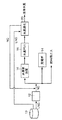
図1は、本発明にかかる液体水素製造システムの一例を示したものである。図において、液化天然ガス(以下、「LNG」と称する)タンク10内には例えば輸送船で運び込まれたLNGが貯留されており、このLNGがLNG気化器12で気化することにより、天然ガス(以下、「NG」と称する。)が生成される。このNGの一部は発電所や燃料需要先へ送られ、残りのNGが水素原料として用いられる。
【0016】
具体的に、前記NGは基本的に水蒸気改質装置16へ導入される。この水蒸気改質装置16は、触媒を収容する触媒室と、前記NGの一部を燃料とするバーナとを備え、このバーナの放射熱により前記触媒室内が加熱された状態で同室内に前記NGと水蒸気とが導入されることにより改質反応が起こり、改質ガスが生成されるようにしたものである(スチームリフォーミング)。この改質ガスは、前記水蒸気改質装置16に付設されるガスボイラやCO変成器を通り、水素ガスに富む混合ガスとして後続の水素PSA装置18に送られる。この水素PSA装置18では、前記混合ガス中の水素以外の成分が吸着除去され、これにより高純度の水素ガスが分離精製される。
【0017】
これらスチームリフォーミング及び水素PSAを用いた高純度水素ガスの精製については周知であり、種々の公知手段が適用可能である(例えば特開2000−327307号公報や特開平9−309703号公報参照)。また、水素ガスを生成するための改質プロセスは前記スチームリフォーミングに限らず、その他の手段、例えば酸素を用いた酸化リフォーミング法(部分酸化法)の適用も可能である。
【0018】
以上のようにして精製された高純度水素ガスは、水素液化装置20にて液化され、製品液体水素として出荷される。さらに、このシステムの特徴として、前記LNGタンク10から送出されるLNGの一部がLNG気化器12を経由せずに直接水素液化装置20に導入され、この水素液化装置20で気化してその気化潜熱により同装置20内での水素ガスの冷却に寄与した後、NGとして水蒸気改質装置16に導入されるようになっている。
【0019】
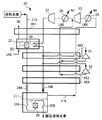
図2は、前記水素液化装置20の具体的構成例を示したものである。図示の水素液化装置20は、図2に示すような液体水素生成ライン21A及び水素循環ライン21Bを有している。
【0020】
前記液体水素生成ライン21Aに導入された高純度水素ガスは、第1段熱交換器HX1で予冷された後、適当な触媒を収容する高温側オルソ−パラ変換器23に導入され、ここで前記水素ガス中のオルソ水素の一部がパラ水素に変換される。これにより、水素ガス中のパラ水素濃度が例えば25%から50%に上昇する。
【0021】
このオルソ−パラ変換は発熱反応であるため、オルソ−パラ変換器23の冷却が必要となるが、この装置の第1の特徴として、前記変換器23の冷却にLNGの気化潜熱が利用されている。
【0022】
具体的に、図示の水素液化装置20は、変換器冷却部としてLNG貯槽22を具備し、このLNG貯槽22内に上述のLNGタンク10から適宜補給されるLNGが貯められるとともに、そのLNG内に前記オルソ−パラ変換器23が浸漬されるように構成されており、このオルソ−パラ変換器23での発熱はLNG貯槽22内のLNGの気化潜熱によって吸収される。換言すれば、オルソ−パラ変換器23の発熱によってLNGの気化が促進され、これにより前記LNG気化器時にとは別にNGの生成が行われる。発生したNGは第1段熱交換器HX1を通って導入水素ガス等と熱交換した後に前記図1に示した水蒸気改質装置16へ原料として導入される。
【0023】
前記オルソ−パラ変換器23でオルソ水素濃度が高められた水素ガスは、熱交換器HX2,HX3,HX4を通ることによりさらに冷却された後、JT弁24Aで断熱膨張(ジュール−トムソン効果を伴う膨張)をして液化する。この液体水素は、液体水素貯槽27内の液体水素中に浸漬された熱交換器25Aを通って低温側オルソ−パラ変換器26内に導入され、この変換器26内で液体水素中に残存するオルソ水素のほぼ全てがパラ水素に変換される。このようにしてパラ水素濃度がほぼ100%となった液体水素は、さらに液体水素貯槽27内の熱交換器25Bを通り、製品としてシステム外へ送り出される。
【0024】
前記液体水素貯槽27内の水素は、前記製品液体水素とは別に、冷媒として水素循環ライン21Bを循環する。具体的には、前記液体水素貯槽27内から多段熱交換器を熱交換器HX4,HX3,HX2,HX1の順に逆行して昇温し、低圧側水素ガス圧縮機C2及び高圧側水素ガス圧縮機C1で圧縮された後、熱交換器HX1、前記LNG貯槽22内に設けられた熱交換器28、熱交換器HX2,HX3,HX4を順に通って冷却され、さらにJT弁24Bで断熱膨張(ジュール−トムソン効果を伴う膨張)をして液化した後に液体水素貯槽27内に還元される。また、熱交換器28を出た水素ガスの一部は膨張タービンT1,T2へ送られ、両膨張タービンT1,T2で断熱膨張することにより寒冷を発生させた後、低圧側水素ガス圧縮機C2の吐出側へ戻される。
【0025】
さらに、この装置の第2の特徴として、各水素ガス圧縮機C1,C2の吸込み側には、各圧縮機よりも手前側で水素ガスを冷却するための水素ガス冷却器28が設けられている。これらの水素ガス冷却器28は、前記LNGタンク10から供給されるLNGと水素ガスとを熱交換させるものであり、その熱交換により、前記LNGが気化してNGが生成されると同時に、その気化潜熱を利用して循環水素ガスの冷却が行われる。ここで生成されたNGも前記と同様に水蒸気改質装置16へ水素原料として送り込まれる。
【0026】
以上説明した方法及びシステムによれば、LNGのもつ気化潜熱(実際にはその気化潜熱に加えて気化後の天然ガスの潜熱)を水素液化装置20での水素ガスの冷却に有効利用することにより、前記LNGの気化によるNGの生成と、水素ガスの液化の双方を、相互補助するようにして効率良く行うことができ、これによりシステム全体の運転効率を飛躍的に高めることができる。
【0027】
具体的に、前記図2に示した水素液化装置20では、LNGの気化潜熱を利用して高温側オルソ−パラ変換器23を冷却することにより、水素ガスのオルソ−パラ変換を促進して水素ガスの液化効率を高めることが可能となり、従来は前記オルソ−パラ変換器23の冷却に必要とされていた液体窒素を不要にすることができる(従来は水素1Nm3あたり0.69Nm3/hの液体窒素を消費。)。
【0028】
また、各水素ガス圧縮機C1,C2に吸い込まれる水素ガスを当該圧縮機C1,C2の手前側で冷却することにより、両圧縮機C1,C2の必要動力を低減して装置全体の運転効率を高めることができる。
【0029】
例えば、従来の2段膨張タービンの基本サイクルでカルノー効率が36%であったとすると、前記水素ガス冷却器28による冷却を実行することにより理論上カルノー効率を60%まで向上させることが可能になり、約0.6kWh/Nm3の動力の節減が可能になる。さらに、水素ガスの冷却によってガス密度を高めることにより、従来の往復式圧縮機に代え、保守費用が低くて連続運転時間が長い遠心圧縮機を適用する道も開かれる。
【0030】
なお、図1に示すシステムにおいて、全LNG供給量のうちLNG気化器12を経由せずに水素液化装置20へ直送するLNG量の比率は、システム全体の運転条件等に応じて適宜設定すればよい。
【0031】
また、水素液化装置20に設けられる熱交換部は図2の例に限らず、例えば次のような形態の選定が可能である。
【0032】
・図4に示すように各圧縮機C1,C2が複数段にわたって直列に設けられている場合には、各圧縮機C1,C2に対応して複数の水素ガス冷却器28を設けるようにしてもよい。
【0033】
・本発明では、前記オルソ−パラ変換器23を冷却するためのLNG貯槽22と水素ガス冷却器28の双方を同時に備えていなくてもよく、後者のみを具備するだけでも従来システムに比して運転効率の向上が可能である。
【0034】
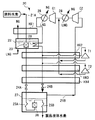
なお、図3は本発明の実施の形態とは別の参考例を示すものであり、この例では水素ガス冷却器28が圧縮機C1,C2の下流側に設けられている。
【0035】
【発明の効果】
以上のように本発明は、液化天然ガスを気化して生成した天然ガスを原料として水素ガスを製造し、その水素ガスを液化して液体水素を製造するにあたり、少なくとも一部の液化天然ガスの気化潜熱を水素液化での水素冷却に利用するようにしたものであるので、効率の高い液体水素の製造を実現できる効果がある。さらに、水素循環ラインの途中に設けられる水素ガス圧縮機に吸い込まれる水素ガスと液化天然ガスとを熱交換させることにより当該水素ガスを当該水素ガス圧縮機の手前側で冷却するとともに前記液化天然ガスを気化させて天然ガスを生成する水素ガス冷却器を含むので、前記水素ガスの冷却によって圧縮機の吸込み体積を減らすことにより、当該圧縮機の必要動力を減らして装置全体の運転効率を高めることができる。
【図面の簡単な説明】
【図1】 本発明にかかる液体水素製造システムの一例を示す全体構成図である。
【図2】 前記水素製造システムに設けられる水素液化装置の一例を示すフローシートである。
【図3】 前記水素液化装置の他の例であって本発明とは別の例を示すフローシートである。
【図4】 前記水素液化装置の水素ガス圧縮機が多段連結された例を示すフローシートである。
【図5】 従来の液体水素製造システムの一例を示す全体構成図である。
【符号の説明】
10 LNGタンク
12 LNG気化器
16 水蒸気改質装置
18 水素PSA装置(分離精製装置)
20 水素液化装置
22 LNG貯槽(熱交換部)
23 オルソ−パラ変換器
24A,24B JT弁
28 水素ガス冷却器
C1,C2 水素ガス圧縮機[0001]
BACKGROUND OF THE INVENTION
The present invention relates to a method and system for producing liquid hydrogen by producing hydrogen gas from a raw material gas and liquefying it.
[0002]
[Prior art]
Conventionally, a system for producing liquid hydrogen from a source gas as shown in FIG. 5 is known. The illustrated
[0003]
As this
[0004]
[Problems to be solved by the invention]
The liquid hydrogen is an important energy source in the industry, but the conventional system requires a great deal of energy to produce the liquid hydrogen. Therefore, how to improve the operating efficiency, particularly how to improve the liquefaction efficiency of hydrogen gas, is a major issue.
[0005]
In view of such circumstances, an object of the present invention is to provide a liquid hydrogen production method and system that enables highly efficient production of liquid hydrogen.
[0006]
[Means for Solving the Problems]
In recent years, natural gas has attracted attention as a raw material gas for liquid hydrogen. This natural gas contains methane as a main component and contains almost no sulfur content, so that there is an advantage that the desulfurization treatment can be simplified or omitted. However, in order to obtain this natural gas, the liquefied natural gas liquefied for transportation must be heated and vaporized, and a large amount of cold heat held by the liquefied natural gas is released during the vaporization. This is the current situation. Therefore, if the cold heat possessed by this liquefied natural gas is effectively used, significant improvement in hydrogen production efficiency can be expected.
[0007]
The present invention was made from such a viewpoint, a liquefied natural gas vaporizer that vaporizes liquefied natural gas to generate natural gas, a hydrogen gas production apparatus that produces hydrogen gas from the natural gas, A hydrogen liquefier that cools and liquefies hydrogen gas, the hydrogen liquefier that cools the hydrogen gas to produce liquid hydrogen, and a liquid hydrogen storage tank that stores liquid hydrogen. A hydrogen circulation line for circulating the hydrogen in the liquid hydrogen storage tank as a refrigerant, and heat for cooling the hydrogen gas by exchanging heat between the hydrogen gas flowing through the liquid hydrogen generation line and the hydrogen flowing through the hydrogen circulation line An exchanger, a hydrogen gas compressor that is provided in the middle of the hydrogen circulation line and compresses the hydrogen gas heated by the heat exchange, and provided on the suction side of the hydrogen gas compressor The hydrogen gas sucked into the hydrogen gas compressor and the liquefied natural gas are heat-exchanged to cool the hydrogen gas on the front side of the hydrogen gas compressor, and the liquefied natural gas is vaporized to generate the natural gas. And a hydrogen gas cooler to be produced.
[0008]
According to this system , when the liquefied natural gas is vaporized to generate natural gas, the latent heat of vaporization is used for cooling the hydrogen gas in the hydrogen liquefaction process, so that the liquefied natural gas is vaporized and the hydrogen gas is liquefied. Both can be performed efficiently, and the hydrogen production efficiency of the entire system can be dramatically increased.
[0009]
Moreover, the hydrogen liquefaction apparatus includes a hydrogen gas compressor provided in the middle of a hydrogen circulation line for circulating hydrogen in the liquid hydrogen storage tank as a refrigerant, hydrogen gas sucked into the hydrogen gas compressor, and liquefied natural gas. A hydrogen gas cooler that cools the hydrogen gas by heat exchange and vaporizes the liquefied natural gas to generate natural gas, thereby reducing the suction volume of the compressor by cooling the hydrogen gas. The required power of the compressor can be reduced and the operating efficiency of the entire apparatus can be increased.
[0010]
The hydrogen gas production apparatus of the hydrogen production system may be any device as long as it can produce high-purity hydrogen gas as a result from natural gas obtained by vaporizing liquefied natural gas. What has the reformer which produces | generates the mixed gas containing gas, and the refinement | purification separation apparatus which refine | purifies and separates hydrogen gas from the mixed gas is suitable.
[0011]
Further, the heat exchange section provided in the hydrogen liquefier may directly cool the hydrogen gas by the latent heat of vaporization of the liquefied natural gas, or by cooling equipment or a heat medium provided in the hydrogen liquefier. The hydrogen gas may be indirectly cooled. For example, in the case where the hydrogen liquefaction apparatus includes an ortho-para converter that converts ortho hydrogen in the introduced hydrogen gas into para hydrogen, the ortho-para conversion reaction is an exothermic reaction, so the heat You may make it include the converter cooling part which makes the said ortho-para converter heat-exchange with liquefied natural gas, and cools it as an exchange part.
[0012]
According to this configuration, by using the latent heat of vaporization of the liquefied natural gas to cool the ortho-para converter, the ortho-para conversion of hydrogen gas can be promoted and the liquefaction efficiency can be increased.
[0013]
More specifically, according to the configuration in which the converter cooling section has a liquefied natural gas storage tank for storing liquefied natural gas, and the ortho-para converter is immersed in the liquefied natural gas, a highly efficient conversion is achieved. The vessel can be cooled.
[0014]
DETAILED DESCRIPTION OF THE INVENTION
A preferred embodiment of the present invention will be described with reference to FIGS.
[0015]
FIG. 1 shows an example of a liquid hydrogen production system according to the present invention. In the figure, LNG carried by, for example, a transport ship is stored in a liquefied natural gas (hereinafter referred to as “LNG”)
[0016]
Specifically, the NG is basically introduced into the
[0017]
These steam reforming and purification of high-purity hydrogen gas using hydrogen PSA are well known, and various known means can be applied (see, for example, JP 2000-327307 A and JP 9-309703 A). . Further, the reforming process for generating hydrogen gas is not limited to the steam reforming, and other means, for example, an oxidation reforming method (partial oxidation method) using oxygen can be applied.
[0018]
The high purity hydrogen gas purified as described above is liquefied by the
[0019]
FIG. 2 shows a specific configuration example of the
[0020]
The high-purity hydrogen gas introduced into the liquid
[0021]
Since this ortho-para conversion is an exothermic reaction, it is necessary to cool the ortho-
[0022]
Specifically, the illustrated
[0023]
The hydrogen gas whose ortho hydrogen concentration has been increased by the ortho-
[0024]
The hydrogen in the liquid
[0025]
Further, as a second feature of this apparatus, a hydrogen gas cooler 28 for cooling the hydrogen gas is provided on the suction side of each of the hydrogen gas compressors C1 and C2 on the front side of each compressor. . These
[0026]
According to the method and system described above, the latent heat of vaporization of LNG (actually, the latent heat of vaporization of natural gas in addition to the latent heat of vaporization) is effectively used for cooling the hydrogen gas in the
[0027]
Specifically, in the
[0028]
In addition, by cooling the hydrogen gas sucked into the hydrogen gas compressors C1 and C2 on the front side of the compressors C1 and C2, the required power of both the compressors C1 and C2 is reduced and the operation efficiency of the entire apparatus is improved. Can be increased.
[0029]
For example, if the Carnot efficiency is 36% in the basic cycle of the conventional two-stage expansion turbine, it is possible to theoretically improve the Carnot efficiency to 60% by executing the cooling by the
[0030]
In the system shown in FIG. 1, the ratio of the LNG amount directly sent to the
[0031]
Moreover, the heat exchange part provided in the
[0032]
As shown in FIG. 4, when the compressors C1 and C2 are provided in series over a plurality of stages, a plurality of
[0033]
In the present invention, both the
[0034]
FIG. 3 shows a reference example different from the embodiment of the present invention. In this example, a
[0035]
【The invention's effect】
As described above, the present invention produces hydrogen gas using natural gas generated by vaporizing liquefied natural gas as a raw material, and liquefies the hydrogen gas to produce liquid hydrogen. Since the latent heat of vaporization is used for hydrogen cooling in hydrogen liquefaction, there is an effect that it is possible to realize highly efficient production of liquid hydrogen. Furthermore, the hydrogen gas sucked into the hydrogen gas compressor provided in the middle of the hydrogen circulation line and the liquefied natural gas are heat-exchanged to cool the hydrogen gas on the front side of the hydrogen gas compressor, and the liquefied natural gas This includes a hydrogen gas cooler that vaporizes the gas to produce natural gas, so that by reducing the suction volume of the compressor by cooling the hydrogen gas, the required power of the compressor is reduced and the overall operation efficiency of the apparatus is increased. Can do.
[Brief description of the drawings]
FIG. 1 is an overall configuration diagram showing an example of a liquid hydrogen production system according to the present invention.
FIG. 2 is a flow sheet showing an example of a hydrogen liquefaction apparatus provided in the hydrogen production system.
FIG. 3 is a flow sheet showing another example of the hydrogen liquefying apparatus and another example of the present invention .
FIG. 4 is a flow sheet showing an example in which hydrogen gas compressors of the hydrogen liquefier are connected in multiple stages.
FIG. 5 is an overall configuration diagram showing an example of a conventional liquid hydrogen production system.
[Explanation of symbols]
10
20
23 Ortho-
Claims (4)
前記天然ガスから水素ガスを製造する水素ガス製造装置と、
前記水素ガスを冷却して液化する水素液化装置とを備え、
この水素液化装置は、
前記水素ガスを冷却して液体水素を生成するための液体水素生成ラインと、
液体水素を貯留する液体水素貯槽と、
この液体水素貯槽内の水素を冷媒として循環させるための水素循環ラインと、
前記液体水素生成ラインを流れる水素ガスを前記水素循環ラインを流れる水素と熱交換させることにより当該水素ガスを冷却する熱交換器と、
前記水素循環ラインの途中に設けられ、前記熱交換により昇温した水素ガスを圧縮する水素ガス圧縮機と、
前記水素ガス圧縮機の吸込み側に設けられ、当該水素ガス圧縮機に吸い込まれる水素ガスと液化天然ガスとを熱交換させることにより当該水素ガスを当該水素ガス圧縮機の手前側で冷却するとともに前記液化天然ガスを気化させて天然ガスを生成する水素ガス冷却器と、を含むことを特徴とする液体水素の製造システム。A liquefied natural gas vaporizer that vaporizes liquefied natural gas to produce natural gas;
A hydrogen gas production apparatus for producing hydrogen gas from the natural gas;
A hydrogen liquefier that cools and liquefies the hydrogen gas,
This hydrogen liquefier
A liquid hydrogen generation line for cooling the hydrogen gas to generate liquid hydrogen;
A liquid hydrogen storage tank for storing liquid hydrogen;
A hydrogen circulation line for circulating hydrogen in the liquid hydrogen storage tank as a refrigerant;
A heat exchanger that cools the hydrogen gas flowing through the liquid hydrogen generation line by heat-exchanging the hydrogen gas flowing through the hydrogen circulation line with the hydrogen flowing through the hydrogen circulation line;
A hydrogen gas compressor that is provided in the middle of the hydrogen circulation line and compresses the hydrogen gas heated by the heat exchange;
The hydrogen gas is provided on the suction side of the hydrogen gas compressor, and the hydrogen gas sucked into the hydrogen gas compressor and the liquefied natural gas are heat-exchanged to cool the hydrogen gas on the front side of the hydrogen gas compressor and A liquid hydrogen production system comprising: a hydrogen gas cooler that vaporizes liquefied natural gas to produce natural gas .
Priority Applications (1)
| Application Number | Priority Date | Filing Date | Title |
|---|---|---|---|
| JP2001215168A JP4429552B2 (en) | 2001-07-16 | 2001-07-16 | Liquid hydrogen production system |
Applications Claiming Priority (1)
| Application Number | Priority Date | Filing Date | Title |
|---|---|---|---|
| JP2001215168A JP4429552B2 (en) | 2001-07-16 | 2001-07-16 | Liquid hydrogen production system |
Publications (2)
| Publication Number | Publication Date |
|---|---|
| JP2003028567A JP2003028567A (en) | 2003-01-29 |
| JP4429552B2 true JP4429552B2 (en) | 2010-03-10 |
Family
ID=19049859
Family Applications (1)
| Application Number | Title | Priority Date | Filing Date |
|---|---|---|---|
| JP2001215168A Expired - Lifetime JP4429552B2 (en) | 2001-07-16 | 2001-07-16 | Liquid hydrogen production system |
Country Status (1)
| Country | Link |
|---|---|
| JP (1) | JP4429552B2 (en) |
Families Citing this family (14)
| Publication number | Priority date | Publication date | Assignee | Title |
|---|---|---|---|---|
| GB0406615D0 (en) * | 2004-03-24 | 2004-04-28 | Air Prod & Chem | Process and apparatus for liquefying hydrogen |
| DE102006027199A1 (en) * | 2006-06-12 | 2007-12-13 | Linde Ag | Process for liquefying hydrogen |
| JP5910105B2 (en) * | 2012-01-23 | 2016-04-27 | セイコーエプソン株式会社 | Sensor device |
| JP6290703B2 (en) * | 2014-05-08 | 2018-03-07 | レール・リキード−ソシエテ・アノニム・プール・レテュード・エ・レクスプロワタシオン・デ・プロセデ・ジョルジュ・クロード | Liquefied gas manufacturing apparatus and manufacturing method |
| US10634425B2 (en) * | 2016-08-05 | 2020-04-28 | L'air Liquide, Societe Anonyme Pour L'etude Et L'exploitation Des Procedes Georges Claude | Integration of industrial gas site with liquid hydrogen production |
| KR102539433B1 (en) | 2018-07-06 | 2023-06-05 | 한화오션 주식회사 | Floating Marine Structure with Hydrogen Storage Tank |
| KR102289476B1 (en) * | 2019-11-26 | 2021-08-12 | 고등기술연구원연구조합 | Hydrogen Liquefaction System and Method |
| KR102328753B1 (en) * | 2019-12-02 | 2021-11-18 | 한국기계연구원 | Hydrogen liquefying apparatus and hydrogen liquefying process |
| KR20220139046A (en) * | 2021-04-07 | 2022-10-14 | 현대자동차주식회사 | Lng reformer system and control method thereof |
| CN113606494B (en) * | 2021-07-29 | 2023-05-09 | 中国科学院合肥物质科学研究院 | A device for producing different components of orthohydrogen and parahydrogen |
| CN114233526A (en) * | 2021-08-11 | 2022-03-25 | 哈尔滨工程大学 | Ammonia reforming system and method for inhibiting natural gas engine knocking and misfiring |
| JP2025012358A (en) * | 2023-07-13 | 2025-01-24 | 三菱重工業株式会社 | Liquefaction device and liquefaction method |
| JP2025012357A (en) * | 2023-07-13 | 2025-01-24 | 三菱重工業株式会社 | Liquefaction device and liquefaction method |
| CN119778635B (en) * | 2025-01-09 | 2025-10-17 | 中海石油气电集团有限责任公司 | Joint production process system and joint production process method |
-
2001
- 2001-07-16 JP JP2001215168A patent/JP4429552B2/en not_active Expired - Lifetime
Also Published As
| Publication number | Publication date |
|---|---|
| JP2003028567A (en) | 2003-01-29 |
Similar Documents
| Publication | Publication Date | Title |
|---|---|---|
| US7559213B2 (en) | Process and apparatus for liquefying hydrogen | |
| JP3086857B2 (en) | Method for generating cold, cooling cycle using this method, and air rectification method and apparatus using this method | |
| CN109690215B (en) | Integration of industrial gas sites with liquid hydrogen production | |
| JP4429552B2 (en) | Liquid hydrogen production system | |
| US7143606B2 (en) | Combined air separation natural gas liquefaction plant | |
| JP3647028B2 (en) | Liquid hydrogen production method and liquid hydrogen production equipment | |
| JP6087196B2 (en) | Low temperature compressed gas or liquefied gas manufacturing apparatus and manufacturing method | |
| US11139497B2 (en) | Fuel cell system using natural gas | |
| US11614280B2 (en) | Reforming system connected with a raw material gas vaporization system | |
| TW202328612A (en) | Hydrogen liquefaction with stored hydrogen refrigeration source | |
| JP4217656B2 (en) | Hydrogen liquefier and liquid hydrogen production system | |
| JP2024542788A (en) | Hydrogen Liquefaction Machine | |
| JP2003002601A (en) | Hydrogen gas production method and hydrogen gas production equipment | |
| JP2022120838A (en) | Method and system for decarbonized LNG production | |
| JP2005134036A (en) | Air separator, and its operating method | |
| JP3208547B2 (en) | Liquefaction method of permanent gas using cold of liquefied natural gas | |
| JP2023548010A (en) | Plant and method for producing hydrogen at cryogenic temperatures | |
| JP4142559B2 (en) | Gas liquefaction apparatus and gas liquefaction method | |
| JP2004150685A (en) | Nitrogen production equipment and turbine power generation equipment | |
| AU2022429663B2 (en) | Process for precooling hydrogen for liquefaction with supplement liquid nitrogen | |
| JPH06241647A (en) | Hydrogen liquefaction equipment and slush hydrogen production equipment | |
| JP2004211969A (en) | Lng cold utilizing system | |
| KR102933087B1 (en) | Hydrogen liquefaction process system comprising autothermal reforming by utilizing liquied oxygen as a pre―coolant | |
| JP2020076514A (en) | Nitrogen gas producing device | |
| CN115597308A (en) | Low-cost high-efficiency liquid hydrogen preparation method |
Legal Events
| Date | Code | Title | Description |
|---|---|---|---|
| A621 | Written request for application examination |
Free format text: JAPANESE INTERMEDIATE CODE: A621 Effective date: 20050214 |
|
| A977 | Report on retrieval |
Free format text: JAPANESE INTERMEDIATE CODE: A971007 Effective date: 20080529 |
|
| A131 | Notification of reasons for refusal |
Free format text: JAPANESE INTERMEDIATE CODE: A131 Effective date: 20080603 |
|
| A521 | Request for written amendment filed |
Free format text: JAPANESE INTERMEDIATE CODE: A523 Effective date: 20080723 |
|
| TRDD | Decision of grant or rejection written | ||
| A01 | Written decision to grant a patent or to grant a registration (utility model) |
Free format text: JAPANESE INTERMEDIATE CODE: A01 Effective date: 20091208 |
|
| A01 | Written decision to grant a patent or to grant a registration (utility model) |
Free format text: JAPANESE INTERMEDIATE CODE: A01 |
|
| A61 | First payment of annual fees (during grant procedure) |
Free format text: JAPANESE INTERMEDIATE CODE: A61 Effective date: 20091216 |
|
| FPAY | Renewal fee payment (event date is renewal date of database) |
Free format text: PAYMENT UNTIL: 20121225 Year of fee payment: 3 |
|
| R150 | Certificate of patent or registration of utility model |
Free format text: JAPANESE INTERMEDIATE CODE: R150 Ref document number: 4429552 Country of ref document: JP Free format text: JAPANESE INTERMEDIATE CODE: R150 |
|
| FPAY | Renewal fee payment (event date is renewal date of database) |
Free format text: PAYMENT UNTIL: 20131225 Year of fee payment: 4 |
|
| R250 | Receipt of annual fees |
Free format text: JAPANESE INTERMEDIATE CODE: R250 |
|
| R250 | Receipt of annual fees |
Free format text: JAPANESE INTERMEDIATE CODE: R250 |
|
| R250 | Receipt of annual fees |
Free format text: JAPANESE INTERMEDIATE CODE: R250 |
|
| R250 | Receipt of annual fees |
Free format text: JAPANESE INTERMEDIATE CODE: R250 |
|
| R250 | Receipt of annual fees |
Free format text: JAPANESE INTERMEDIATE CODE: R250 |
|
| R250 | Receipt of annual fees |
Free format text: JAPANESE INTERMEDIATE CODE: R250 |
|
| R250 | Receipt of annual fees |
Free format text: JAPANESE INTERMEDIATE CODE: R250 |
|
| R250 | Receipt of annual fees |
Free format text: JAPANESE INTERMEDIATE CODE: R250 |
|
| R250 | Receipt of annual fees |
Free format text: JAPANESE INTERMEDIATE CODE: R250 |
|
| EXPY | Cancellation because of completion of term |