JP4426448B2 - Die with multiple orifice slots - Google Patents
Die with multiple orifice slots Download PDFInfo
- Publication number
- JP4426448B2 JP4426448B2 JP2004527570A JP2004527570A JP4426448B2 JP 4426448 B2 JP4426448 B2 JP 4426448B2 JP 2004527570 A JP2004527570 A JP 2004527570A JP 2004527570 A JP2004527570 A JP 2004527570A JP 4426448 B2 JP4426448 B2 JP 4426448B2
- Authority
- JP
- Japan
- Prior art keywords
- slot
- orifice
- long side
- die
- longitudinal
- Prior art date
- Legal status (The legal status is an assumption and is not a legal conclusion. Google has not performed a legal analysis and makes no representation as to the accuracy of the status listed.)
- Expired - Fee Related
Links
- 239000000463 material Substances 0.000 claims abstract description 15
- 230000009969 flowable effect Effects 0.000 claims abstract description 11
- 239000011800 void material Substances 0.000 claims abstract description 7
- 238000000034 method Methods 0.000 claims description 7
- 238000003491 array Methods 0.000 claims 2
- 239000012530 fluid Substances 0.000 description 40
- 238000000576 coating method Methods 0.000 description 23
- 239000011248 coating agent Substances 0.000 description 21
- 238000001125 extrusion Methods 0.000 description 11
- 230000003068 static effect Effects 0.000 description 10
- 239000007788 liquid Substances 0.000 description 3
- 239000000758 substrate Substances 0.000 description 3
- 238000005304 joining Methods 0.000 description 2
- 238000011144 upstream manufacturing Methods 0.000 description 2
- 230000015572 biosynthetic process Effects 0.000 description 1
- 238000005266 casting Methods 0.000 description 1
- 238000010276 construction Methods 0.000 description 1
- 238000007766 curtain coating Methods 0.000 description 1
- 230000007547 defect Effects 0.000 description 1
- 238000006073 displacement reaction Methods 0.000 description 1
- 238000009826 distribution Methods 0.000 description 1
- 239000012467 final product Substances 0.000 description 1
- 238000004519 manufacturing process Methods 0.000 description 1
- 239000012528 membrane Substances 0.000 description 1
- 239000002184 metal Substances 0.000 description 1
- 238000012986 modification Methods 0.000 description 1
- 230000004048 modification Effects 0.000 description 1
- 230000000704 physical effect Effects 0.000 description 1
- 229920000642 polymer Polymers 0.000 description 1
- 239000002861 polymer material Substances 0.000 description 1
- 230000002265 prevention Effects 0.000 description 1
- 238000007767 slide coating Methods 0.000 description 1
Images


Classifications
-
- B—PERFORMING OPERATIONS; TRANSPORTING
- B05—SPRAYING OR ATOMISING IN GENERAL; APPLYING FLUENT MATERIALS TO SURFACES, IN GENERAL
- B05C—APPARATUS FOR APPLYING FLUENT MATERIALS TO SURFACES, IN GENERAL
- B05C5/00—Apparatus in which liquid or other fluent material is projected, poured or allowed to flow on to the surface of the work
- B05C5/02—Apparatus in which liquid or other fluent material is projected, poured or allowed to flow on to the surface of the work the liquid or other fluent material being discharged through an outlet orifice by pressure, e.g. from an outlet device in contact or almost in contact, with the work
- B05C5/027—Coating heads with several outlets, e.g. aligned transversally to the moving direction of a web to be coated
-
- B—PERFORMING OPERATIONS; TRANSPORTING
- B05—SPRAYING OR ATOMISING IN GENERAL; APPLYING FLUENT MATERIALS TO SURFACES, IN GENERAL
- B05C—APPARATUS FOR APPLYING FLUENT MATERIALS TO SURFACES, IN GENERAL
- B05C5/00—Apparatus in which liquid or other fluent material is projected, poured or allowed to flow on to the surface of the work
- B05C5/02—Apparatus in which liquid or other fluent material is projected, poured or allowed to flow on to the surface of the work the liquid or other fluent material being discharged through an outlet orifice by pressure, e.g. from an outlet device in contact or almost in contact, with the work
-
- B—PERFORMING OPERATIONS; TRANSPORTING
- B29—WORKING OF PLASTICS; WORKING OF SUBSTANCES IN A PLASTIC STATE IN GENERAL
- B29C—SHAPING OR JOINING OF PLASTICS; SHAPING OF MATERIAL IN A PLASTIC STATE, NOT OTHERWISE PROVIDED FOR; AFTER-TREATMENT OF THE SHAPED PRODUCTS, e.g. REPAIRING
- B29C48/00—Extrusion moulding, i.e. expressing the moulding material through a die or nozzle which imparts the desired form; Apparatus therefor
- B29C48/16—Articles comprising two or more components, e.g. co-extruded layers
- B29C48/18—Articles comprising two or more components, e.g. co-extruded layers the components being layers
Abstract
Description
本発明は、コーティングダイおよび押出ダイに関する。特に本発明はコーティングオリフィスまたは押出オリフィスの構成に関する。 The present invention relates to a coating die and an extrusion die. In particular, the invention relates to the construction of a coating orifice or extrusion orifice.
連続スロットを有するコーティングダイおよび押出ダイは製造および設定に費用がかかる。連続スロット流体担持ダイの加工および設定費用は多額である。均一な供給スロットを維持することは、スロットを出る流体が連続断面輪郭を維持するという点で有利である。クロスウェブ方向の供給スロットの均一性を維持するためにはダイが大型でなければならず、スロットの周囲に適正な構造支持体を提供するためには複雑な載置設定が必要となる。「クロスウェブ」方向は一般に、ダイに対して並進する基材(通例、紙またはポリマ材料のウェブ)の幅寸法として規定される。「クロスウェブ」方向はダイに対するウェブの進行方向に対して直交している。「クロスウェブ」方向を用いてダイ、ウェブ上の塗膜、押出物またはウェブ自体の方向を説明し得る。 Coating dies and extrusion dies with continuous slots are expensive to manufacture and set up. Processing and setup costs for continuous slot fluid carrying dies are significant. Maintaining a uniform supply slot is advantageous in that the fluid exiting the slot maintains a continuous cross-sectional profile. To maintain the uniformity of the feed slot in the cross-web direction, the die must be large, and complex placement settings are required to provide the proper structural support around the slot. The “cross web” direction is generally defined as the width dimension of a substrate (typically a web of paper or polymer material) that translates relative to the die. The “cross web” direction is perpendicular to the direction of web travel relative to the die. The “cross web” direction may be used to describe the direction of the die, the coating on the web, the extrudate, or the web itself.
多数のオリフィスを有するダイは連続スロットダイの安価な代替物を提供してきた。多数オリフィスダイは多数の開口部を有し、それにより流体(例えば液体)はダイの分配チャンバを流出可能であった。流体の連続断面輪郭を提供するために、ダイを通って移動する流体をオリフィスを通過した後に外部のランドまたはトラフを用いて合流させていた。例えば流体担持ダイにおいて流体がダイを出た箇所の下流で、個々の流体流を合流させてウェブ上で連続流体塗膜にするためにダイの一部を用いていた(「平滑ランド」と称されることが多い)。通例、平滑ランドの下流部は、塗膜のうねりおよび間隙を防止するために用いられる鋭敏な刃で終端していた。平滑ランドの長さは普通下流方向においてオリフィスから鋭敏な刃までで測定される。他のタイプのダイは、流体が塗布される前にダイ内の流体を収集して合流させる「トラフ」を用いて流れを結合していた。多数オリフィスの例は、米国特許第3,149,949号明細書、同4,774,109号明細書、同5,045,358号明細書、および同4,371,571号明細書に図示および説明されており、それらの全体はこの引用をもって本明細書に記載されているものとする。 Dies with multiple orifices have provided an inexpensive alternative to continuous slot dies. Multiple orifice dies have multiple openings so that fluid (eg, liquid) can flow out of the die distribution chamber. In order to provide a continuous cross-sectional profile of the fluid, the fluid traveling through the die was merged using an external land or trough after passing through the orifice. For example, in a fluid-carrying die, downstream of where the fluid exits the die, a portion of the die was used to join the individual fluid streams into a continuous fluid coating on the web (referred to as “smooth land”). Often). Typically, the downstream portion of the smooth land was terminated with a sharp blade that was used to prevent undulation and gaps in the coating. The length of the smooth land is usually measured from the orifice to the sharp blade in the downstream direction. Other types of dies combined flow using “troughs” that collect and merge the fluid in the die before the fluid was applied. Examples of multiple orifices are shown in U.S. Pat. Nos. 3,149,949, 4,774,109, 5,045,358, and 4,371,571. Which are hereby incorporated by reference in their entirety.
これらの以前の多数オリフィス型ダイからの隣接流体流は、流体の連続断面輪郭を形成するためにウェブまたは他の基材上に塗布する(または押し出す)前に合流させなければならないため、以前のこのタイプのダイは連続、平滑、および無気泡のコーティング(または押出)層を提供するために、コーティング(または押出)パラメータ(例えばライン速度、ダイ設定、コーティング(または押出)膜の所望の厚さ、ダイ位置等)の範囲が幾分狭い。これは隣接オリフィスにより作製される別々の流体流を合流させるために必要とされる技術に起因する。特に厄介なのは2つの流れの合流地点である。この地点で流体と基材との間に空気が閉じ込められることが多く、最終製品に欠陥を生じる恐れがある。 Because adjacent fluid streams from these previous multi-orifice dies must be merged before being applied (or extruded) on a web or other substrate to form a continuous cross-sectional profile of the fluid, This type of die provides a desired thickness of coating (or extrusion) parameters (eg, line speed, die setting, coating (or extrusion) film to provide a continuous, smooth, and bubble-free coating (or extrusion) layer. , Die position, etc.) range is somewhat narrow. This is due to the technique required to merge the separate fluid streams created by adjacent orifices. Particularly troublesome is the confluence of the two streams. At this point, air is often trapped between the fluid and the substrate, which can cause defects in the final product.
本発明は流動性材料を分配するためのダイである。ダイはダイブロックで構成されている。外面がダイブロック上に配置されている。少なくとも1つのスロットが外面内へ直交して延びている。スロットは長手方向寸法、第1の長辺および第2の長辺、並びに少なくとも2つの互いに接続されていない空隙を有する。少なくとも1つの支持部材が少なくとも2つの空隙の間を外面からスロット内へ延びている。支持部材は第1の長辺から第2の長辺へ連続して延びている。支持部材の少なくとも一部が長手方向寸法と直交する以外の方向に配置されている。支持部材はスロットの長手方向寸法と直交する方向において第1の長辺から第2の長辺ヘ延びる任意の平面の少なくとも一部が空隙領域を通過するように配置されている。 The present invention is a die for dispensing a flowable material. Die is composed of a da Eve lock. The outer surface is arranged on Dive lock. At least one slot extends orthogonally into the outer surface. The slot has a longitudinal dimension , a first long side and a second long side, and at least two unconnected voids . At least one support member extends from the outer surface into the slot between at least two voids . The support member extends continuously from the first long side to the second long side. At least a part of the support member is disposed in a direction other than perpendicular to the longitudinal dimension. The support member is arranged such that at least a part of an arbitrary plane extending from the first long side to the second long side passes through the gap region in a direction orthogonal to the longitudinal dimension of the slot.
本開示においていくつかの装置を図示する。図面全体を通して同様の参照符号を用いることによりこれらの装置の共通する特徴または構成要素を示す。 Several devices are illustrated in the present disclosure. Throughout the drawings, like reference numerals are used to indicate common features or components of these devices.
上記の図面は本発明のいくつかの好適な実施形態を説明するが、説明で言及するように他の実施形態も考えられる。いずれの場合もこの開示は本発明を限定ではなく例示の目的で提示する。なお当業者には本発明の原理の範囲と精神との中にある多数の他の変更例および実施形態を考案可能であることは理解できよう。 While the above drawings illustrate some preferred embodiments of the invention, other embodiments are also contemplated, as mentioned in the description. In any case, this disclosure presents the invention by way of illustration and not limitation. It will be appreciated by those skilled in the art that numerous other modifications and embodiments can be devised which are within the scope and spirit of the principles of the present invention.
本発明の代表的なダイが図1の10に概略的に図示されている。ダイ10は流体12(すなわち流動性材料)がウェブ14上へと外へ移動してコーティング16を形成するフリースパンコーティングプロセスで用いられている状態で示されている。ダイ10の長手(「クロスウェブ」)方向を矢印17で示す。長手方向17はダイ10に対してウェブ14の進行方向と直交している。ウェブ14はポリマ類または紙を始めとする多様な材料で形成することができる。ウェブ14は配向ローラ20Aおよび20B上を矢印18で示す方向に移動する。ローラ20Aはダイ10より上流位置でウェブ14を支持し、ローラ20Bはダイ10より下流位置でウェブ14を支持して、それによりダイ10がコーティング16として流体12を塗布する「フリースパン」のウェビング材料が作製される。フリースパン型流体担持コーティングプロセスを図示しているが、本発明のダイ10は多数の他のタイプのコーティングおよび押出プロセス、なかでも一定間隔のコーティング、カーテンコーティングおよびスライドコーティングと共に利用し得る。さらにはダイ10の形状は最終ユーザのプロセスおよび用途により変更し得る。
A representative die of the present invention is schematically illustrated at 10 in FIG. Die 10 is shown being used in a free span coating process in which fluid 12 (ie, flowable material) moves out onto
本発明のダイ10の一実施形態の断面図が図2に図示されている。ダイ10はブロック部24と面板部26とを含むダイブロック22を含む。マニホールド28がブロック部24の内側に形成されている。図示したダイブロック22は2つの部分で形成されているが、任意の数の部分を用いてダイブロック22を形成してもよい。例えばブロック部24を破線で示したように第1と第2の部分30Aと30Bとに分割することができる(例えばボルト締めまたは型締めによる)。ダイ10の面板部26がブロック部24とは別に形成されている場合、異なる面板部26を同じブロック部24上で利用することも可能である。代替的にはブロック部24および面板部26を金属の1つの一体部分で形成してダイブロック22を形成することができる。外面32がダイブロック22の面板部26上に配置されている。スロット34がマニホールド28と連通した状態で面板部26の外面32内へ延びている。
A cross-sectional view of one embodiment of the die 10 of the present invention is illustrated in FIG. Die 10 includes a Dive lock 22 including the
流体材料12は通例、当技術で周知のような押出機などのポンプ(図示せず)または容積式ポンプ(例えばなかでもギヤポンプまたは定量ポンプ)によってマニホールド28内に導入される。ポンプによって生じるマニホールド28内の圧力により、流体12がスロット34の外に押し出される。流体12はスロット34から出る際に面板部26の外面32を濡らすとともに第1および第2のスタティックライン36Aおよび36Bを形成する。スタティックラインは当技術で周知であり、流体12と、外面32と、ダイ10を取り囲む環境(通例空気)または場合によっては流体の他の層(例えば多層コーティングダイにおける)のいずれかとの接合ラインとして規定することができる。スタティックライン36A、36Bは、スロット34の各側においてダイ10上に形成され、幅寸法37によって規定される。スロット34の幅寸法37は最上流オリフィス40Bの縁41Aと最下流オリフィス40Aの縁41Bとの間に規定される(図3参照)。再び図2を参照すると、流体材料12は面板部26上で外面32とほぼ平行な方向に流れる。この方向は概して参照符号39により示される。流体12がウェブ14(鎖線で示す)上でコーティング(またはフィルム)16を形成するように、ダイ10はウェブ14に対向して配置可能である。代替的にはダイ10を用いて、当技術で周知のように注入型押出プロセスの場合と同様に流体12を独立型フィルムとして押し出してもよい。さらには多層の流体をダイ10により押出またはコーティングすることもできる。
The
図3は本発明のダイ10の外面32の第1の実施形態を図示する。スロット34が長手方向寸法17に延びている状態で示されている。スロット34は鎖線で示された第1の長辺38Aと第2の長辺38Bとを有する。複数のオリフィス(または空隙領域)40が面板部26の外面32内へ延びている。複数の支持部材42は、個々の支持部材42Aが各隣接オリフィス40Aと40Bとの間になるように配置されている。なおオリフィスおよび支持部材を広く参照する場合は参照符号のみを用いる(すなわち「オリフィス40」および「支持部材42」)が、特定のオリフィスまたは支持部材を参照する場合は文字を付ける(すなわち「オリフィス40A」および「支持部材42A」)ものとする。
FIG. 3 illustrates a first embodiment of the
支持部材42は、長手(クロスウェブ)寸法17と直交する方向において第1の長辺38Aと第2の長辺38Bとの間に配置された任意の平面(矢印44で示す)の少なくとも一部が少なくとも1つのオリフィス(または空隙)40を通過するように、スロット34の第1の長辺38Aから第2の長辺38Bへ連続して延びている。
The
図示の実施形態において、支持部材42は第1および第2の長辺38Aおよび38Bに対して約60°の角度で第1および第2の長辺38Aおよび38Bから延びている。一実施形態において各支持部材の厚さ(長手方向17の)は約5ミル(約130ミクロン)(参照符号45で示す)以下であり、スロット幅37は約40ミル(約1020ミクロン)以下であるが、この大きさおよび幅は最終用途により変更可能である。このように支持部材42を配置することにより概して正三角形の形状のオリフィス40が形成される。9個のオリフィス40が図示されているが、その数は最終用途(例えばスロット34の長さ)により変更可能である。外面32からスロット34内へ延びる支持部材42の長さは最終用途により変更可能である。
In the illustrated embodiment, the
スロット34内の支持部材42の形成は本出願で検討する様々な方法で達成可能である。例えばオリフィス40を外面32内に機械加工(例えば穿孔)してもよいし、あるいはシムまたはインサートの一部(図3Aに鎖線46によって随意のものとして図示する)として形成してもよい。シム46は、上述したようにダイブロック22にスロット34を規定するために用いてもよいし、支持構造42およびオリフィス40を有してもよい。シム46(一般的な使用法は周知である)を用いてスロット34内に支持部材42およびオリフィス40を収容した場合、シム46をダイ10から外して以下に図4、5、6、7、および8に関して説明するような支持部材42およびオリフィス40の異なる構成を有する代替シム(図示せず)と取り替えることによりスロット34の構成を変更することができる。
Formation of the
支持部材42が第1の長辺38Aから第2の長辺38Bまで連続的に延びることにより、第1および第2の長辺38Aおよび38Bに凸状または凹状の「反り」が生じてスロット34が変形することが防止される。「反り」は流体(例えば液体)12をダイ10を通して押し出すのに必要な圧力により生じ、流体12の物理的特性(例えば粘度)により変化し得る。ある代表的なコーティングおよび押出プロセスでは、スロット34の長辺38Aおよび38B上で約5psi(約34kPa)の圧力〜約100psi(約690kPa)の圧力が生じ得る。このレベルの圧力は支持部材42で耐えられる。
As the
「反り」の防止は、ダイ幅にわたってスロット34を出る(すなわちオリフィス40を通過する)流体12の流量に高レベルの均一性をもたらす。流体(例えば液体)12の流れ方向におけるオリフィス40の部分的重複すなわちオーバーラップ(平面44により例示する)が、オリフィス40を出る際に流体12の流れを部分的に重複させることにより、クロスウェブ方向の流体膜の断面連続性を維持する。換言すれば間隙および気泡を最小限に抑えられ、流体の連続層(または膜)がクロスウェブ方向(すなわちダイ10の長手方向寸法17)においてウェブ14上に塗布される(または押し出される)ようになっている。これはダイ10の長手方向寸法17に沿った各平面44において空隙またはオリフィス40が流体12を放出しているため発生する。そのためスロット34内の構造(すなわち支持部材42)の利点(例えば「反り」を防止する)を利用する一方、連続塗膜流体層12を形成することができる。この「オーバーラップ」はウェブ14上の流体12を示すオリフィス40の間の鎖線により図示されている。オーバーラップにより、平滑ランドまたはトラフ(すなわち外面32内へ延びる連続溝)などのスロット34のさらに下流の流体の別々な流れを接合させるための構造を提供する必要性が最小限に抑えられる。これによりダイ10を通して流体12を押し出すのに必要な圧力に耐える所望の強度を有する一方で最小限の物理的空間しか必要としない、より小さいダイの利用が可能になる。
Prevention of “warping” provides a high level of uniformity in the flow rate of
第1のスタティックライン36Aはスロット34の第1の長辺38Aに近接して配置されている。第2のスタティックライン36Bは第2の長辺38Bに近接して配置されている。なおスタティックライン36Aおよび36Bの位置は、行われるコーティングまたは押出のタイプ、なかでもコーティングおよび押出の設定により外面32上の位置に応じて変化し得る。例えば第1のスタティックライン36Aを支持構造42の一部上に配置してもよい。なお第1のスタティックライン36Aは、第2の長辺38Bよりも第1の長辺38Aに近接して外面32上に配置されている。さらには第2のスタティックライン36Bは、第1の長辺38Aよりも第2の長辺38Bに近接して外面32上に配置されている。支持構造42により規定される各オリフィス40の断面形状(すなわち外面32とほぼ平行な平面における)は実質的にスロット幅37全体に延びていることが好ましい。換言すれば外面32における各オリフィス40の幅(概して長手方向17に直交して規定される)はスロット幅37と実質的に同じである。この好適な構成を図3〜4Aおよび6〜8に図示された実施形態により詳細に例示する。スロット34と実質的に同じ幅を有するオリフィス40を提供することで本発明のダイ10の性能特性が向上し、塗布速度の高速化および塗膜16の厚さの制御が可能になる。
The first static line 36 </ b> A is disposed close to the first long side 38 </ b> A of the
本発明のダイ10の第2の実施形態が図4に図示されている。この実施形態において断面形状が長円形のオリフィス50は斜め支持部材52によって形成されている。支持部材52は、スロット34の長手方向寸法17と直交する方向においてスロット34の第1と第2の長辺38Aと38Bとの間に延びる平面44が少なくとも1つのオリフィス(または空隙)50を通過するように構成されている。また図4Aに図示するように、それにより流体12がオリフィス50から放出される際に流体のオーバーラップを生じさせて、クロスウェブ方向に連続断面輪郭を形成する。前述したようにオリフィス50および支持部材52の大きさおよび数は(本明細書で説明するすべての実施形態と同様に)最終用途により変更可能である。
A second embodiment of the
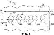
図5は本発明のダイ10の第3の実施形態を図示している。この実施形態において楕円形状を有するオリフィス60が面板部26の外面32内に配置されている。支持部材62はオリフィス60の間に延びてスロット34を「反り」から防止する構造を提供する。明確な直線形状を有してはいないが、個々の支持部材62A、62B,62Cおよび62Dは、長辺38Aおよび38Bと直交するように配置された平面44が少なくとも1つのオリフィス(または空隙)60を通過できるような形状に形成されている。
FIG. 5 illustrates a third embodiment of the
図5Aに図示するように、これによりオリフィス60を通って移動する流体12は、オリフィス60からウェブ14上を下流(矢印64)へ移動する際に「オーバーラップ」可能になり、長手方向寸法17のエアギャップおよび不連続を最小限に抑える(好適には排除する)ことができる。
As shown in Figure 5A, the fluid 12 thus travels through the
図6〜8は本発明のダイ10の更なる実施形態を図示する。具体的には図6は外面32に台形オリフィス(または空隙)70を形成する支持部材72を図示している。図7は外面32内に平行四辺形状のオリフィス(または空隙)80を形成する支持部材82を図示している。図8は外面32に突き出る五角形状のオリフィス(または空隙)90を形成する支持部材92を図示している。図6〜8により図示された実施形態の各々において、スロット34の長手方向寸法17と直交する方向においてスロット34の第1と第2の長辺38Aと38Bとの間に延びる平面44を規定することができる。スロット34の長手方向寸法17に沿った各平面44は少なくとも1つのオリフィス(または空隙)(それぞれ図6,7および8において参照番号70、80および90で示す)を通過して延びている。本発明の精神と範囲とから逸脱することなく、任意の数の支持部材72、82および92並びにオリフィス70、80および90を本発明のダイにおいて利用することができる。このことは、外面32にわたるスタティックライン36Bの長手方向17を示す直線からの若干のずれおよびさらなる安定性によってもたらされる。なお図9Bに図示するような一実施形態において、外面32の長手方向寸法17に沿って部分的に延びる多数のスロット34を用いてもよい。これらの多数のスロット34は支持構造42および52によって離間したオリフィス(参照番号により示す)40および50を含む。さらには本発明のダイにおいて、任意の組合せまたは数の列(例えば多数の膜層)ならびに任意の数および任意の形状のオリフィスを組合せて用いることができる。例えば図9Aに図示するように3つのスロットを外面32の長手方向寸法17に沿って延びるように「積み重ねる」ことにより、3つのフィルム層を作製することもできる。各スロット34は支持構造のない連続スロットを始めとする異なるオリフィス形状(図示のような)を有することもできる。代替的にはオリフィス形状は各スロットにおいて内部変更することができる。
6-8 illustrate further embodiments of the
好適な実施形態を参照して本発明を説明したが、本発明の精神と範囲とから逸脱することなく形状および細部において変更可能であることは当業者には理解できよう。 Although the present invention has been described with reference to preferred embodiments, workers skilled in the art will recognize that changes may be made in form and detail without departing from the spirit and scope of the invention.
Claims (4)
前記ダイブロック上に配置された外面と、
前記外面内へ直交して延びるとともに、長手方向寸法、第1の長辺および第2の長辺、並びに少なくとも2つの互いに接続されていない空隙を有する少なくとも1つのスロットと、
前記外面から前記スロット内へ延び、前記第1の長辺から前記第2の長辺へ前記少なくとも2つの空隙の間を連続して延びる少なくとも1つの支持部材とを含み、
前記少なくとも2つの空隙は一列状に配置され、前記スロットの各々は前記外面を部分的に長手方向に延び、前記支持部材の少なくとも一部が前記長手方向寸法と直交する以外の方向に配置され、前記スロットの前記長手方向寸法と直交する方向において前記第1の長辺から前記第2の長辺ヘ延びる任意の平面の少なくとも一部が空隙領域を通過するようになっており、
前記一列状に配置された空隙の任意の空隙を通って前記長手方向に平行に延びるいかなる直線も、前記一列状に配置された空隙の全てを通るようになっている、流動性材料を分配するためのダイ。Die block,
An outer surface disposed on the die block;
At least one slot extending orthogonally into the outer surface and having a longitudinal dimension, a first long side and a second long side, and at least two non-connected gaps;
Before extending from Kigaimen into said slot, and at least one support member extending continuously between said first long side of said at least two air gaps to the second long side,
The at least two gaps are arranged in a row, each of the slots extends partially in the longitudinal direction on the outer surface, and at least a portion of the support member is arranged in a direction other than perpendicular to the longitudinal dimension; At least a portion of an arbitrary plane extending from the first long side to the second long side in a direction orthogonal to the longitudinal dimension of the slot passes through the void region ;
Distributes the flowable material such that any straight line extending parallel to the longitudinal direction through any of the rows of voids arranged in a row passes through all of the voids arranged in a row. Die for.
第1の長辺と第2の長辺との間を延びる前記外面内に位置する長手方向寸法を有し、前記外面を前記長手方向に部分的に延びるスロットと、
前記外面内へ延びて、前記外面と平行な長手方向配列寸法と、前記長手方向配列寸法と直交するとともに前記外面と平行な幅とを規定する、互いに接続されていない複数のオリフィスを含む少なくとも1つのオリフィス配列とを含み、
前記オリフィス配列に含まれる任意のオリフィスを通って前記スロットの前記長手方向寸法に平行に延びるいかなる直線も、前記オリフィス配列に含まれるオリフィスの全てを通るようになっており、
各オリフィスの少なくとも一部が、前記オリフィス配列の長手方向配列寸法のいずれにおいても幅方向内に配置されるように前記オリフィスが配置されている、流動性材料を分配するためのダイ。At least one die block having a manifold and an outer surface;
A slot having a longitudinal dimension located within the outer surface extending between a first long side and a second long side, the slot partially extending in the longitudinal direction on the outer surface;
Extending into said outer surface, a longitudinal array dimension the outer surface parallel, as well as perpendicular to the longitudinal array dimension defining with said outer surface parallel to the width of at least 1, including a plurality of orifices which are not connected to each other Two orifice arrays ,
Any straight line extending parallel to the longitudinal dimension of the slot through any orifice included in the orifice array passes through all of the orifices included in the orifice array;
At least a portion of each orifice, the longitudinal said orifice so is also disposed within the width direction in either direction array dimension is disposed, die for dispensing flowable material of the orifice or array.
ダイブロックを用意するステップであって、該ダイブロックは、
前記ダイブロック上に配置された外面と、
前記外面内へ直交して延びるとともに、長手方向寸法、第1の長辺および第2の長辺、並びに少なくとも2つの互いに接続されていない空隙を有する少なくとも1つのスロットと、
前記外面から前記スロット内へ延び、前記第1の長辺から前記第2の長辺へ前記少なくとも2つの空隙の間を連続して延びる少なくとも1つの支持部材とを含み、
前記少なくとも2つの空隙は一列状に配置され、前記スロットの各々は前記外面を部分的に長手方向に延び、前記支持部材の少なくとも一部が前記長手方向寸法と直交する以外の方向に配置され、前記スロットの前記長手方向寸法と直交する方向において前記第1の長辺から前記第2の長辺ヘ延びる任意の平面の少なくとも一部が空隙領域を通過するようになっている、ダイブロックを用意するステップと、
前記少なくとも1つのスロットを介して流動性材料を移動させる一方で、前記スロットの長手方向に沿った前記流動性材料の連続性を維持するステップと、を有する方法。A method for dispensing flowable material through a die, comprising:
Preparing a die block, the die block comprising:
An outer surface disposed on the die block;
At least one slot extending orthogonally into the outer surface and having a longitudinal dimension, a first long side and a second long side, and at least two non-connected gaps;
Including at least one support member extending from the outer surface into the slot and continuously extending between the at least two gaps from the first long side to the second long side;
The at least two gaps are arranged in a row, each of the slots extends partially in the longitudinal direction on the outer surface, and at least a portion of the support member is arranged in a direction other than perpendicular to the longitudinal dimension; A die block is provided, wherein at least a part of any plane extending from the first long side to the second long side in a direction orthogonal to the longitudinal dimension of the slot passes through the void region. And steps to
Moving the flowable material through the at least one slot while maintaining continuity of the flowable material along the length of the slot .
少なくとも1つのダイブロックを用意するステップであって、該ダイブロックは、 Providing at least one die block, the die block comprising:
第1の長辺と第2の長辺との間を延びる外面内に位置する長手方向寸法を有し、前記外面を前記長手方向に部分的に延びるスロットと、 A slot having a longitudinal dimension located within an outer surface extending between the first long side and the second long side, and a slot partially extending the outer surface in the longitudinal direction;
前記外面内へ延びて、前記外面と平行な長手方向配列寸法と、前記長手方向配列寸法と直交するとともに前記外面と平行な幅とを規定する、互いに接続されていない複数のオリフィスを含む少なくとも1つのオリフィス配列とを含み、 At least one including a plurality of non-connected orifices extending into the outer surface and defining a longitudinal array dimension parallel to the outer surface and a width orthogonal to the longitudinal array dimension and parallel to the outer surface Two orifice arrays,
前記オリフィス配列に含まれる任意のオリフィスを通って前記スロットの前記長手方向寸法に平行に延びるいかなる直線も、前記オリフィス配列に含まれるオリフィスの全てを通るようになっており、 Any straight line extending parallel to the longitudinal dimension of the slot through any orifice included in the orifice array passes through all of the orifices included in the orifice array;
各オリフィスの少なくとも一部が、前記オリフィス配列の長手方向配列寸法のいずれにおいても幅方向内に配置されるように前記オリフィスが配置されている、ダイブロックを用意するステップと、 Providing a die block in which the orifices are disposed such that at least a portion of each orifice is disposed within the width direction in any of the longitudinal array dimensions of the orifice array;
前記スロット及び前記オリフィス配列を介して流動性材料を移動させる一方で、前記スロットの長手方向に沿った前記流動性材料の連続性を維持するステップと、を有する方法。 Moving the flowable material through the slot and the orifice arrangement while maintaining the continuity of the flowable material along the length of the slot.
Applications Claiming Priority (2)
| Application Number | Priority Date | Filing Date | Title |
|---|---|---|---|
| US10/217,715 US7591903B2 (en) | 2002-08-13 | 2002-08-13 | Die having multiple orifice slot |
| PCT/US2003/018950 WO2004014570A1 (en) | 2002-08-13 | 2003-06-17 | Die having multiple orifice slot |
Publications (3)
| Publication Number | Publication Date |
|---|---|
| JP2005535441A JP2005535441A (en) | 2005-11-24 |
| JP2005535441A5 JP2005535441A5 (en) | 2006-07-13 |
| JP4426448B2 true JP4426448B2 (en) | 2010-03-03 |
Family
ID=31714421
Family Applications (1)
| Application Number | Title | Priority Date | Filing Date |
|---|---|---|---|
| JP2004527570A Expired - Fee Related JP4426448B2 (en) | 2002-08-13 | 2003-06-17 | Die with multiple orifice slots |
Country Status (11)
| Country | Link |
|---|---|
| US (2) | US7591903B2 (en) |
| EP (1) | EP1528958B1 (en) |
| JP (1) | JP4426448B2 (en) |
| KR (1) | KR100984199B1 (en) |
| CN (1) | CN100352560C (en) |
| AT (1) | ATE449649T1 (en) |
| AU (1) | AU2003245519A1 (en) |
| BR (1) | BR0313392B1 (en) |
| DE (1) | DE60330247D1 (en) |
| HK (1) | HK1079481A1 (en) |
| WO (1) | WO2004014570A1 (en) |
Families Citing this family (29)
| Publication number | Priority date | Publication date | Assignee | Title |
|---|---|---|---|---|
| JP3957640B2 (en) * | 2002-02-21 | 2007-08-15 | アイシン化工株式会社 | Wide slit nozzle and coating method with wide slit nozzle |
| JP4974580B2 (en) * | 2006-05-08 | 2012-07-11 | 日東電工株式会社 | Die system coating apparatus and coating method |
| US9340053B2 (en) | 2006-11-15 | 2016-05-17 | 3M Innovative Properties Company | Flexographic printing with curing during transfer to substrate |
| US20100024671A1 (en) * | 2006-11-15 | 2010-02-04 | Pekurovsky Mikhail L | Solvent-assisted embossing of flexographic printing plates |
| WO2008060875A1 (en) * | 2006-11-15 | 2008-05-22 | 3M Innovative Properties Company | Solvent removal assisted material transfer for flexographic printing |
| JP5348244B2 (en) | 2009-04-22 | 2013-11-20 | トヨタ自動車株式会社 | Battery electrode manufacturing method and coating die used therefor |
| US8752501B2 (en) | 2010-07-29 | 2014-06-17 | Corning Incorporated | Systems and methods for dispensing a fluid |
| EP2444163A1 (en) | 2010-10-23 | 2012-04-25 | Andreas Otto | Nozzle |
| US20120135194A1 (en) * | 2010-11-24 | 2012-05-31 | Honda Motor Co., Ltd. | High-viscosity material application device, high-viscosity material application method, and high-viscosity material coating |
| JP5632720B2 (en) * | 2010-11-24 | 2014-11-26 | 本田技研工業株式会社 | High viscosity material applicator |
| US9700912B2 (en) | 2012-06-27 | 2017-07-11 | William K. Leonard | Fluid transport media |
| KR101357820B1 (en) * | 2012-09-19 | 2014-02-05 | 반석정밀공업주식회사 | Multi-point discharging head that binding to the dispenser |
| BR112015022744A2 (en) | 2013-03-13 | 2017-07-18 | 3M Innovative Properties Co | entanglements, arrays and manufacturing methods |
| US10737287B2 (en) | 2014-01-21 | 2020-08-11 | Illinois Tool Works Inc. | Fluid application device having a modular contact nozzle with a fluidic oscillator |
| US9718084B2 (en) * | 2014-01-21 | 2017-08-01 | Illinois Tool Works Inc. | Fluid application device having a modular contact nozzle with a fluidic oscillator |
| WO2015126931A1 (en) | 2014-02-18 | 2015-08-27 | 3M Innovative Properties Company | Easy to apply air and water barrier articles |
| US10040234B2 (en) * | 2014-05-27 | 2018-08-07 | Nordson Corporation | Multi-manifold extrusion die with deckle system and method of using same |
| WO2016106273A1 (en) | 2014-12-22 | 2016-06-30 | 3M Innovative Properties Company | Air and water barrier articles |
| CN105014906B (en) * | 2015-07-29 | 2017-08-25 | 大连三奥挤出模具开发有限公司 | A kind of forming method of section bar |
| EP3337867B1 (en) | 2015-08-18 | 2024-04-10 | 3M Innovative Properties Company | Air and water barrier article with porous layer and liner |
| CN108025326A (en) * | 2015-09-29 | 2018-05-11 | 金伯利-克拉克环球有限公司 | Adhesive applicator with revolving valve |
| CN109414720A (en) * | 2016-08-04 | 2019-03-01 | 积水化学工业株式会社 | The manufacturing method of die applicator, the manufacturing device of dye-sensitized solar cells and battery |
| WO2018156631A1 (en) | 2017-02-23 | 2018-08-30 | 3M Innovative Properties Company | Air and water barrier article including inelastic porous layer |
| US20210300808A1 (en) * | 2018-08-10 | 2021-09-30 | Corning Incorporated | Apparatus and methods for fabricating a glass ribbon |
| EP3894094B1 (en) | 2018-12-13 | 2024-04-24 | 3M Innovative Properties Company | Method and apparatus of slot die coating over deformable back-up roll |
| WO2021137123A1 (en) | 2019-12-31 | 2021-07-08 | 3M Innovative Properties Company | Multilayer articles via wet-on-wet processing |
| US11865571B2 (en) | 2019-12-31 | 2024-01-09 | 3M Innovative Properties Company | Die coating on air supported shell |
| US20230149969A1 (en) | 2020-04-03 | 2023-05-18 | 3M Innovative Properties Company | Slot Die Coating Using Concave Die Lip Over Deformable Back-Up Roll |
| US20230391071A1 (en) * | 2020-09-25 | 2023-12-07 | Hewlett-Packard Development Company, L.P. | Fluidic dies |
Family Cites Families (28)
| Publication number | Priority date | Publication date | Assignee | Title |
|---|---|---|---|---|
| US3256081A (en) * | 1957-04-24 | 1966-06-14 | Saint Gobain | Manufacture of flat glass |
| US3149949A (en) * | 1961-02-27 | 1964-09-22 | Corning Glass Works | Downflow sheet drawing method and apparatus |
| US4324816A (en) * | 1975-05-22 | 1982-04-13 | Eastman Kodak Company | Method for forming a stripe by extrusion coating |
| US4142010A (en) * | 1977-01-17 | 1979-02-27 | International Business Machines Corporation | Method for applying a viscous fluid to a substrate |
| US4106437A (en) * | 1977-08-22 | 1978-08-15 | Eastman Kodak Company | Apparatus for multiple stripe coating |
| US4371571A (en) * | 1979-08-27 | 1983-02-01 | Acumeter Laboratories, Inc. | Wide-band and continuous line adhesive applicator and method for cigarette filter attachment and the like |
| US4391856A (en) * | 1979-08-27 | 1983-07-05 | Acumeter Laboratories, Inc. | Adhesive applicator and method for cigarette-to-filter adhesion and similar applications |
| US4386998A (en) * | 1979-08-27 | 1983-06-07 | Acumeter Laboratories, Inc. | Adhesive applicator and method for cigarette-to-filter adhesion and similar applications |
| IT8267442A0 (en) * | 1982-04-05 | 1982-04-05 | Rotomec Costr Mecc | DEVICE FOR SPREADING A SUBSTANCE ONTO A TAPE MATERIAL |
| US4774109A (en) * | 1987-07-21 | 1988-09-27 | Nordson Corporation | Method and apparatus for applying narrow, closely spaced beads of viscous liquid to a substrate |
| US5045358A (en) * | 1989-10-30 | 1991-09-03 | Matsushita Electric Industrial Co., Ltd. | Coating head assembly and coating method |
| JPH0538478A (en) | 1991-08-06 | 1993-02-19 | Konica Corp | Coating device |
| JP3113100B2 (en) * | 1992-11-05 | 2000-11-27 | 株式会社デンソー | Multi-hole tube extrusion die and multi-hole tube |
| JP3220265B2 (en) * | 1992-12-28 | 2001-10-22 | 株式会社康井精機 | Coating equipment |
| DE4402226C2 (en) * | 1994-01-27 | 1997-11-06 | Voith Gmbh J M | Doctor device |
| US5700325A (en) * | 1994-08-03 | 1997-12-23 | Matsushita Electric Industrial Co., Ltd. | Coating device and a method of coating |
| MX9701941A (en) * | 1994-09-16 | 1997-06-28 | Avery Dennison Corp | Method and apparatus for multilayer die coating. |
| JPH08103711A (en) | 1994-10-04 | 1996-04-23 | Chugai Ro Co Ltd | Die coater |
| US5769947A (en) * | 1994-10-22 | 1998-06-23 | Itw Dynatech Gmbh Klebetechnik | Applicator for adhesive and corresponding nozzle plate |
| CN1093783C (en) | 1996-02-21 | 2002-11-06 | 松下电器产业株式会社 | Liquid application nozzle, method of manufacturing same, liquid application method, liquid application device, and method of manufacturing cathode-ray tube |
| US5720816A (en) * | 1996-03-08 | 1998-02-24 | Beloit Technologies, Inc. | Reverse feed film applicator |
| US5871585A (en) * | 1996-03-20 | 1999-02-16 | Minnesota Mining And Maufacturing Company | Apparatus for applying a fluid to a moving web of material |
| WO1999055790A1 (en) | 1998-04-24 | 1999-11-04 | Minnesota Mining And Manufacturing Company | Striped adhesive-coated tape |
| JP3992413B2 (en) * | 1998-12-28 | 2007-10-17 | 富士フイルム株式会社 | Image forming method and apparatus |
| EP1016537B1 (en) * | 1998-12-28 | 2004-03-03 | Fuji Photo Film Co., Ltd. | Method and apparatus for forming image with plural coating liquids |
| US6695923B1 (en) * | 2000-11-21 | 2004-02-24 | Sealant Equipment & Engineering, Inc. | Multiple orifice applicator system and method of using same |
| US7749565B2 (en) * | 2006-09-29 | 2010-07-06 | General Electric Company | Method for applying and dimensioning an abradable coating |
| US7752995B2 (en) * | 2007-05-22 | 2010-07-13 | Johnson & Johnson Inc. | Slot-coating apparatus |
-
2002
- 2002-08-13 US US10/217,715 patent/US7591903B2/en not_active Expired - Lifetime
-
2003
- 2003-06-17 WO PCT/US2003/018950 patent/WO2004014570A1/en active Application Filing
- 2003-06-17 AU AU2003245519A patent/AU2003245519A1/en not_active Abandoned
- 2003-06-17 CN CNB038194597A patent/CN100352560C/en not_active Expired - Lifetime
- 2003-06-17 AT AT03739149T patent/ATE449649T1/en not_active IP Right Cessation
- 2003-06-17 KR KR1020057002469A patent/KR100984199B1/en active IP Right Grant
- 2003-06-17 DE DE60330247T patent/DE60330247D1/en not_active Expired - Lifetime
- 2003-06-17 EP EP03739149A patent/EP1528958B1/en not_active Expired - Lifetime
- 2003-06-17 BR BRPI0313392-3B1A patent/BR0313392B1/en not_active IP Right Cessation
- 2003-06-17 JP JP2004527570A patent/JP4426448B2/en not_active Expired - Fee Related
-
2005
- 2005-12-15 HK HK05111544A patent/HK1079481A1/en not_active IP Right Cessation
-
2009
- 2009-06-25 US US12/491,378 patent/US7846504B2/en not_active Expired - Lifetime
Also Published As
| Publication number | Publication date |
|---|---|
| DE60330247D1 (en) | 2010-01-07 |
| HK1079481A1 (en) | 2006-04-07 |
| US7591903B2 (en) | 2009-09-22 |
| US20090261499A1 (en) | 2009-10-22 |
| US20040032050A1 (en) | 2004-02-19 |
| JP2005535441A (en) | 2005-11-24 |
| KR100984199B1 (en) | 2010-09-28 |
| WO2004014570A1 (en) | 2004-02-19 |
| BR0313392A (en) | 2005-06-21 |
| KR20050065529A (en) | 2005-06-29 |
| EP1528958B1 (en) | 2009-11-25 |
| EP1528958A1 (en) | 2005-05-11 |
| CN100352560C (en) | 2007-12-05 |
| US7846504B2 (en) | 2010-12-07 |
| ATE449649T1 (en) | 2009-12-15 |
| AU2003245519A1 (en) | 2004-02-25 |
| CN1674999A (en) | 2005-09-28 |
| BR0313392B1 (en) | 2013-12-24 |
Similar Documents
| Publication | Publication Date | Title |
|---|---|---|
| JP4426448B2 (en) | Die with multiple orifice slots | |
| US6423140B1 (en) | Die set for preparing ABCABC multiple-stripe coating | |
| US8752501B2 (en) | Systems and methods for dispensing a fluid | |
| US6159544A (en) | Apparatus and method for forming a coating layer of multiple stripes | |
| US4669965A (en) | Multi-layer extrusion die | |
| JP2009022867A (en) | Slot nozzle assembly, slot coating gun, shim plate, and method of extruding foamable melted material in wide band | |
| JPH0631789A (en) | Method and equipment for producing multilayer polymer film | |
| IE54019B1 (en) | Multicomponent continuous film die | |
| US20110268906A1 (en) | Co-extrusion die, method of extruding with the die, and extruded articles made therefrom | |
| JP2012179502A (en) | Slot nozzle assembly and shim plate | |
| US4880163A (en) | Gas feeding nozzle for a chemical vapor deposition apparatus | |
| JPH08142149A (en) | Composite resin sheet and apparatus and method for producing the same | |
| US5814258A (en) | Method for forming multilayer sheet or multilayer film | |
| JP4882331B2 (en) | Laminate sheet manufacturing apparatus and method | |
| JP4409961B2 (en) | Die lip for strip coating | |
| CN115245889B (en) | Die head | |
| JPH0899056A (en) | Coating apparatus and coating method | |
| KR20130051401A (en) | Curtain coater | |
| JP2001310149A (en) | Die set for stripe coating, method for stripe coating, and stripe-coated product | |
| KR100665240B1 (en) | Coating head | |
| JP2014030938A (en) | Multilayer extrusion molding apparatus | |
| JP2001009894A (en) | Foamed sheet molding die and foamed sheet molding apparatus | |
| JPH07230085A (en) | Method and apparatus for producing liquid crystal display device | |
| JP2023025608A (en) | Mixing prevention coating device | |
| JPH0638659Y2 (en) | Laminating device for multi-layer extrusion machine |
Legal Events
| Date | Code | Title | Description |
|---|---|---|---|
| A521 | Request for written amendment filed |
Free format text: JAPANESE INTERMEDIATE CODE: A523 Effective date: 20060525 |
|
| A621 | Written request for application examination |
Free format text: JAPANESE INTERMEDIATE CODE: A621 Effective date: 20060525 |
|
| A131 | Notification of reasons for refusal |
Free format text: JAPANESE INTERMEDIATE CODE: A131 Effective date: 20090609 |
|
| A521 | Request for written amendment filed |
Free format text: JAPANESE INTERMEDIATE CODE: A523 Effective date: 20090908 |
|
| TRDD | Decision of grant or rejection written | ||
| A01 | Written decision to grant a patent or to grant a registration (utility model) |
Free format text: JAPANESE INTERMEDIATE CODE: A01 Effective date: 20091110 |
|
| A01 | Written decision to grant a patent or to grant a registration (utility model) |
Free format text: JAPANESE INTERMEDIATE CODE: A01 |
|
| A61 | First payment of annual fees (during grant procedure) |
Free format text: JAPANESE INTERMEDIATE CODE: A61 Effective date: 20091210 |
|
| R150 | Certificate of patent or registration of utility model |
Free format text: JAPANESE INTERMEDIATE CODE: R150 |
|
| FPAY | Renewal fee payment (event date is renewal date of database) |
Free format text: PAYMENT UNTIL: 20121218 Year of fee payment: 3 |
|
| FPAY | Renewal fee payment (event date is renewal date of database) |
Free format text: PAYMENT UNTIL: 20121218 Year of fee payment: 3 |
|
| FPAY | Renewal fee payment (event date is renewal date of database) |
Free format text: PAYMENT UNTIL: 20131218 Year of fee payment: 4 |
|
| R250 | Receipt of annual fees |
Free format text: JAPANESE INTERMEDIATE CODE: R250 |
|
| R250 | Receipt of annual fees |
Free format text: JAPANESE INTERMEDIATE CODE: R250 |
|
| R250 | Receipt of annual fees |
Free format text: JAPANESE INTERMEDIATE CODE: R250 |
|
| R250 | Receipt of annual fees |
Free format text: JAPANESE INTERMEDIATE CODE: R250 |
|
| LAPS | Cancellation because of no payment of annual fees |