CN100352560C - Die having multiple orifice slot - Google Patents
Die having multiple orifice slot Download PDFInfo
- Publication number
- CN100352560C CN100352560C CNB038194597A CN03819459A CN100352560C CN 100352560 C CN100352560 C CN 100352560C CN B038194597 A CNB038194597 A CN B038194597A CN 03819459 A CN03819459 A CN 03819459A CN 100352560 C CN100352560 C CN 100352560C
- Authority
- CN
- China
- Prior art keywords
- mould
- vertical side
- line
- rabbet joint
- module
- Prior art date
- Legal status (The legal status is an assumption and is not a legal conclusion. Google has not performed a legal analysis and makes no representation as to the accuracy of the status listed.)
- Expired - Lifetime
Links
- 239000000463 material Substances 0.000 claims abstract description 22
- 239000011800 void material Substances 0.000 claims abstract description 4
- 239000012530 fluid Substances 0.000 claims description 39
- 238000000576 coating method Methods 0.000 claims description 27
- 230000003068 static effect Effects 0.000 claims description 13
- 238000010276 construction Methods 0.000 claims description 11
- 238000003825 pressing Methods 0.000 claims description 11
- 238000000034 method Methods 0.000 claims description 8
- 238000013459 approach Methods 0.000 claims description 3
- 230000015572 biosynthetic process Effects 0.000 claims description 3
- 230000009969 flowable effect Effects 0.000 abstract 1
- 239000011248 coating agent Substances 0.000 description 23
- 239000007788 liquid Substances 0.000 description 10
- 238000005452 bending Methods 0.000 description 6
- 238000010586 diagram Methods 0.000 description 3
- 239000000758 substrate Substances 0.000 description 3
- 230000008901 benefit Effects 0.000 description 2
- 230000014509 gene expression Effects 0.000 description 2
- 238000000465 moulding Methods 0.000 description 2
- 238000012545 processing Methods 0.000 description 2
- 238000011144 upstream manufacturing Methods 0.000 description 2
- 238000005266 casting Methods 0.000 description 1
- 238000007766 curtain coating Methods 0.000 description 1
- 238000013461 design Methods 0.000 description 1
- 238000007723 die pressing method Methods 0.000 description 1
- 238000006073 displacement reaction Methods 0.000 description 1
- 238000009826 distribution Methods 0.000 description 1
- 238000005516 engineering process Methods 0.000 description 1
- 239000012467 final product Substances 0.000 description 1
- 238000007755 gap coating Methods 0.000 description 1
- 238000009434 installation Methods 0.000 description 1
- 238000012423 maintenance Methods 0.000 description 1
- 238000004519 manufacturing process Methods 0.000 description 1
- 239000002184 metal Substances 0.000 description 1
- 238000012986 modification Methods 0.000 description 1
- 230000004048 modification Effects 0.000 description 1
- 230000000704 physical effect Effects 0.000 description 1
- 229920000642 polymer Polymers 0.000 description 1
Images


Classifications
-
- B—PERFORMING OPERATIONS; TRANSPORTING
- B05—SPRAYING OR ATOMISING IN GENERAL; APPLYING FLUENT MATERIALS TO SURFACES, IN GENERAL
- B05C—APPARATUS FOR APPLYING FLUENT MATERIALS TO SURFACES, IN GENERAL
- B05C5/00—Apparatus in which liquid or other fluent material is projected, poured or allowed to flow on to the surface of the work
- B05C5/02—Apparatus in which liquid or other fluent material is projected, poured or allowed to flow on to the surface of the work the liquid or other fluent material being discharged through an outlet orifice by pressure, e.g. from an outlet device in contact or almost in contact, with the work
- B05C5/027—Coating heads with several outlets, e.g. aligned transversally to the moving direction of a web to be coated
-
- B—PERFORMING OPERATIONS; TRANSPORTING
- B29—WORKING OF PLASTICS; WORKING OF SUBSTANCES IN A PLASTIC STATE IN GENERAL
- B29C—SHAPING OR JOINING OF PLASTICS; SHAPING OF MATERIAL IN A PLASTIC STATE, NOT OTHERWISE PROVIDED FOR; AFTER-TREATMENT OF THE SHAPED PRODUCTS, e.g. REPAIRING
- B29C48/00—Extrusion moulding, i.e. expressing the moulding material through a die or nozzle which imparts the desired form; Apparatus therefor
- B29C48/16—Articles comprising two or more components, e.g. co-extruded layers
- B29C48/18—Articles comprising two or more components, e.g. co-extruded layers the components being layers
Abstract
The invention is a die for dispensing flowable material. The die is comprised of a die block. An external face is disposed on the die block. At least one slot extends perpendicularly into the external face. The slot has a longitudinal dimension, a first longitudinal side and a second longitudinal side. At least one support member extends from the external surface into the slot. The support member extends continuously from the first longitudinal side to the second longitudinal side. At least a portion of the support member is disposed in a direction other than perpendicular to the longitudinal dimension. The support member is disposed to such that at least a portion of any plane extending from the first longitudinal side to the second longitudinal side, in a direction perpendicular to the longitudinal dimension of the slot, passes through a void area.
Description
Background of invention
The present invention relates to mould coating and mold pressing.More particularly, the present invention relates to be coated with or the structure in mold pressing hole.
The manufacturing and the installation cost of mould that coating and mold pressing have the continuous line of rabbet joint is very expensive.The processing and the adjustment expense of line of rabbet joint liquid-bearing are very high continuously.Keep the benefit of the charging line of rabbet joint of homogeneous to be that the liquid that flows out the line of rabbet joint keeps continuous cross section.In order to cross over the unified charging slot of net direction maintenance, mould must greatly and need meticulous erecting device so that the abundant supporting construction around slot to be provided." leap net " direction typically refers to the width dimensions that substrate (being generally a slice paper or polymeric material) is moved with respect to mould." leap net " direction is perpendicular to the moving direction of net with respect to mould." leap net " direction can be used to explain the direction of mould, online coating, extrudate or net itself.
The mould that has a plurality of holes provides the selection of less expensive for succeeding vat slit die tool.Porous mold has many openings makes fluid (for example, liquid) flow out die distribution chamber.For the fluid in continuous cross section is provided, the fluid that moves through mould utilizes external lands or groove to converge after passing the hole.For example, in the mould of carrying fluid, flow out mould in its downstream fluid, a part of mould is used for independent liquid stream is converged in the continuous flow that is coated on net (being commonly referred to " smooth engagement face ").Typically, the downstream end of smooth engagement face is a sharp edge, is used to prevent corded and forms breach on coating.The length of smooth engagement face is measured at downstream direction usually, for from the hole to the sharp edge.Current are converged in the mould utilization " groove " of other type, and described groove collected and converged the fluid in the mould before the coating fluid.The example diagram of porous and be described in United States Patent (USP) 3,149,949; 4,774,109; 5,045,358; And in 4,371,571, all the elements all are incorporated herein by reference.
Because from must before being coated in online or other substrate, (or mold pressing) converging of these above-mentioned porous type moulds so that form the continuous cross section of fluid in abutting connection with liquid stream, previous such mould have sometimes than close limit coating (or extruding) parameter (for example, linear velocity, mould is installed, the thickness of coating (or mold pressing) film of expectation, die location or the like), smoothly and not contains coating (or mold pressing) layer of bubble so that provide continuously.This is because the described technology that needs to have the separated liquid stream of adjacent holes generation to converge.Especially difficulty is the point of two liquid streams.Air is sneaked into the fault that causes final product between fluid and the substrate in this point usually.
Summary of the invention
The present invention is the mould of dispenses fluid material.Mould is made up of module.Outer surface is positioned on the module.At least one line of rabbet joint extends vertically up in the outer surface.The line of rabbet joint has size longitudinally, first vertical side and second vertical side 38b.At least one support member extends to the line of rabbet joint from outer surface.Support member extends to second vertical side from first vertical side continuously.At least a portion support member is positioned at the direction non-perpendicular to longitudinal size.The placement of support member makes at least a portion pass interstice coverage in the direction perpendicular to the longitudinal size of the line of rabbet joint from arbitrary face that first vertical side extends to second vertical side.
A kind of mould that distributes stream material that the present invention relates to comprises:
Module;
Be positioned at the outer surface on the module;
At least one extends vertically up in the outer surface and has longitudinal size, the line of rabbet joint of first vertical side and second vertical side;
At least one extends into the support member of the line of rabbet joint from outer surface, and described support member extends to second vertical side from first vertical side continuously; And
Therefore wherein at least a portion support member is positioned at the direction that is not orthogonal to longitudinal size, passes at least one interstice coverage in the direction perpendicular to the longitudinal size of the line of rabbet joint from least a portion that first vertical side extends to arbitrary of second vertical side continuously.
A kind of mould that is used to distribute stream material that the present invention relates to comprises:
At least one has the module of manifold and outer surface;
A plurality of void area that at least one array hole limits extend to outer surface so that limit the longitudinal size parallel with outer surface, and perpendicular to longitudinal size and be parallel to the width of outer surface;
And
The placement of its mesopore makes at least a portion in each hole be positioned on each width of hole array longitudinal size.
The present invention relates to a kind of method of distributing stream material to pass mould simultaneously, comprising:
Stream material is moved through be arranged in the line of rabbet joint of mold outer surface, the described line of rabbet joint has longitudinal size, first vertical side and second vertical side;
The shape that keeps the line of rabbet joint with at least one supporting construction that extends to the line of rabbet joint from outer surface and between first longitudinal edge and second longitudinal edge, extend continuously; And
By supporting construction to small part being placed on direction non-perpendicular to longitudinal size, make at least a portion pass interstice coverage, thereby keep stream material along line of rabbet joint continuity longitudinally with arbitrary plane of direction between first vertical side and second vertical side perpendicular to line of rabbet joint longitudinal size.
Description of drawings
In of the present invention disclosing, illustrate several means.In institute's drawings attached, similarly reference number is used for showing the common characteristic or the parts of those devices.
Accompanying drawing 1 is the schematic diagram of an embodiment of mould of the present invention.
Accompanying drawing 2 is cross sectional views of an embodiment of mould of the present invention.
Accompanying drawing 3 is part front views of an embodiment of mould of the present invention.
Accompanying drawing 3A is the part front view of an embodiment of mould of the present invention.
Accompanying drawing 4 is part front views of second embodiment of mould of the present invention.
Accompanying drawing 4A is the part front view of second embodiment of mould of the present invention.
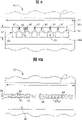
Accompanying drawing 5 is part front views of the 3rd embodiment of mould of the present invention.
Accompanying drawing 5A is the part front view of the 3rd embodiment of mould of the present invention.
Fig. 6 is the part front view of the 4th embodiment of mould of the present invention.
Fig. 7 is the part front view of the 5th embodiment of mould of the present invention.
Fig. 8 is the part front view of the 6th embodiment of mould of the present invention.
Fig. 9 A is the part front view of the 7th embodiment of mould of the present invention.
Fig. 9 B is the part front view of the 8th embodiment of mould of the present invention.
Though above-mentioned accompanying drawing has been set forth several embodiment preferred of the present invention, other embodiment is also included within the above-mentioned discussion.With regard to all situations, this openly nonrestrictive mode proposes to enumerate.Know that very those skilled in the art can design many other modification and embodiments, as long as in the spirit and scope of principle of the present invention.
Detailed Description Of The Invention
Exemplary mold of the present invention be illustrated in accompanying drawing 1 10 in.The mould 10 that shows is used in the free span coating process, wherein fluid 12 (i.e. the material of Liu Donging) thus be removed to formation coating 16 on the net 14.Vertical (or " cross web ") direction of mould 10 is indicated by arrow 17.Vertical 17 with respect to the moving direction of mould 10 perpendicular to net 14.Net 14 can comprise that polymer or paper form by numerous different materials.Net 14 moves through deflector roll 20A and 20B in the direction by arrow 18 expressions.Roller 20A is supported on net 14 in mould 10 upstreams, and roller 20B is supported on the downstream position of mould 10 with net 14, produces into " the free span " of net materials, and coating fluid 12 is as coating 16 on described one-tenth net material.Though graphic is the coating process of free span liquid-bearing, mould 10 of the present invention can be used with the coating and the die pressing of many other types, comprises the fixed gap coating, curtain coating and sliding surface coating etc.In addition, the shape of mould 10 can be according to terminal use's processing and application and is different.
The cross sectional view of an embodiment of mould 10 of the present invention is illustrated among Fig. 2.Mould 10 comprises module 22, and it comprises module section 24 and faceplate part 26.Manifold 28 is module section 24 inner formation.Though graphic module 22 forms by two sections, the Duan Jun of arbitrary quantity can be used for forming module 22.For example, module 22 can be divided into first and second sections 30A and the 30B (for example, fixing by bolt or anchor clamps) that is shown by dotted line.When the faceplate part 26 of mould 10 individually when module section 24 forms, realized on identical module section 24, using different faceplate parts 26.Perhaps, module section 24 and faceplate part 26 can be formed to form module 22 by a complete metal.Outer surface 32 is positioned on the faceplate part 26 of module 22.The line of rabbet joint 34 extends in the outer surface 32 of the faceplate part 26 that is connected with manifold 28.
Flowing material is general by pump (not shown) known in the art, is imported into manifold 28 such as moulding press or positive-displacement pump (for example, gear pump or measuring pump (etc.).The pressure that is produced in manifold 28 by pump forces fluid 12 to flow out the line of rabbet joint 34.When fluid 12 when the line of rabbet joint 34 flows out, the outer surface 32 of faceplate part 26 got wet and formed first and second static line 36A and the 36B.Static line is well known in the art and can be restricted to fluid 12, outer surface 32 and on every side around mould 10 (generally being air) or may be the connection circuit (for example, in the multioperation coating die) of another layer fluid.Static line 36A forms on the mould 10 on each side of the line of rabbet joint 34, such as width dimensions 37 definition.The width dimensions 37 of the line of rabbet joint 34 is limited between the edge 41B of the edge 41A of upstream orifice 40B and downstream aperture 40A.Flowing material 12 is in usually parallel with outer surface 32 on the faceplate part 26 direction inflow.Direction is shown by reference number 39 usually.Mould 10 can be against net 14 (being shown in dotted line) thereby is placed and make fluid 12 form coating (or film) 16 on net 14.Perhaps, mould 10 can be used to independently film of mold pressing fluid 12 conducts, such as in casting mold process known in the art.
In addition, can be by mould 10 mold pressings or coating multiple fluid.
Fig. 3 illustrates first embodiment of the outer surface 32 of mould 10 of the present invention.The line of rabbet joint 34 demonstrates and extends in longitudinally in the size 17.The line of rabbet joint 34 has first vertical side 38A and second the vertical side 38B that is shown by dotted line.A plurality of holes (or interstice coverage) 40 extend in the outer surface 32 of faceplate part 26.Placing a plurality of support members 42 makes independent support member 42A between the sharp 40B of each adjacent holes 40A.It should be noted that when mentioning hole and support member, will only use reference number (i.e. " hole 40 " and " support member 42 "), yet, when mentioning concrete hole or support member, will add a letter (i.e. " hole 40A " and " support member 42A ").
In graphic embodiment, support member 42 from first and second vertical side 38A and 38B with the angles of about 60 degree with respect to first vertical side and second vertical side 38A and 38B extension.In one embodiment, the thickness of each support member (vertical 17) is less than or equal to about 5 mils (about 130 microns) (being expressed as numeral 45), and groove width 37 is less than or equal to about 40 mils (about 1020 microns), though size and width can change according to final application.The support member of placing in this way 42 forms the hole 40 that is shaped as equilateral triangle usually.Though illustrate 9 holes 40, its quantity can be according to final application and different (for example, the length of the line of rabbet joint 34).The distance that extends to the support member 42 the line of rabbet joint 34 from outer surface 32 can change according to final application.
Can form support member at the line of rabbet joint 34 by the different modes of considering among the application.For example, hole 40 can be processed (for example boring) in outer surface 32, or form part pad or insert (by 46 optional demonstrations of the dotted line among Fig. 3 A).Pad 46 can be used to limit the line of rabbet joint 34 and comprise described supporting construction 42 and hole 40 in module 22.When pad 46 (its common application is known) is used for comprising supporter 42 in the line of rabbet joint 34 and hole 40, its make the line of rabbet joint 34 structure by from mould its 10 remove pad 46 and with other such as following accompanying drawing 4,5,6, the 7 pad (not shown)s of describing with different support member 42 and hole 40 structures replace being changed.
Thereby support member 42 runs to second vertical side 38B from first vertical side 38A continuously and makes that first and second vertical side 38A and 38B are prevented from making the line of rabbet joint 34 distortion thus in protruding or recessed mode " bending ".Because " bending " takes place the pressure that needs propelling fluid (for example liquid) 12 to pass mould 10, and described bending can be according to the physical property (for example viscosity) of fluid 12 and difference.Some typical coating and mold process can be on vertical side 38A of the line of rabbet joint 34 and 38B the pressure of generation from the pressure of about 5psi (about 34kPa) to about 100psi (about 690kPa).Supported 42 of this stress level prevented.
Prevent that " bending " provides fluid 12 to flow out the highly homogeneous flow velocity of the line of rabbet joint 34 (promptly passing hole 40) when crossing die width.In the direction that fluid (for example liquid) 12 flows, hole 40 (by plane 44 illustrations) overlapping makes and the stream " overlapping " of when fluid tap hole 40 fluid 12 kept the cross section continuity of fluid film in leap net direction thus.In other words, slit and bubble are minimized so that with the pantostrat (or film) of fluid in the direction of the crossing over net longitudinal size 17 of mould 10 (promptly) applied (or extruding) on net 14.This is because along each plane 44 of the longitudinal size 17 of mould 10, space or hole 40 discharge fluid 12.Therefore, can utilize the advantage (for example preventing " bending ") of structure in the slot 34 (being support member 42), still discharge continuous coating fluid layer 12 simultaneously.Described " overlapping " represents the fluid 12 on the net 14 by the explanation of the dotted line between the hole 40.Overlapping feasible needs for the structure that the separated flow that connects the line of rabbet joint 34 farther place downstream fluid is provided minimize described structure such as smooth engagement face or groove (promptly extending to the continuous groove in the outer surface 32).This makes to use to have expection intensity and need the less mould in minimal physical space to bear the pressure that needs propelling fluid 12 to pass mould 10.
First vertical side 38A of the most contiguous line of rabbet joint 34 of the first static line 36A.The second static line 36B the most contiguous second vertical side 38B.It should be noted that according to the coating of being carried out or the type of mold pressing, and coating and molding device etc., the position of static line 36A and 36B can change with respect to the position on the outer surface 32.For example, the first static line 36A can be placed on a part of supporting construction 42.Should notice also that the first static line 36A is positioned at than second vertical side 38B and more approach on the outer surface 32 of first vertical side 38A.In addition, the second circuit 36B is positioned at than first vertical side 38A and more approaches on the outer surface 32 of second vertical side 38B.Preferably the shape of cross section (plane that promptly is parallel to outer surface 32 usually) in each hole 40 that is limited by supporting construction 42 extends whole groove width 37 basically.In other words, the width of each hole 40 at outer surface 32 places (being limited to usually perpendicular to vertical 17 places) is substantially the same with groove width 37.This is preferably constructed especially by Fig. 3-4A and the illustrated embodiment illustration of 6-8.The performance characteristic that has improved mould 10 of the present invention with the hole 40 of the line of rabbet joint 34 substantially the same width is provided, thereby can adopts the thickness of higher coating speed and control coating 16.
Second embodiment of mould 10 of the present invention is illustrated among Fig. 4.In this embodiment, be that oval-shaped hole 50 is formed by diagonal support members 52 at cross section.At least one hole (or space) 50 is passed in being arranged so that on the plane 44 that the direction perpendicular to the longitudinal size 17 or the line of rabbet joint 34 extends between first and second vertical sides of the line of rabbet joint 34 of support member 52.On the other hand, shown in Fig. 4 A, when fluid 12 tap holes 50, provide the overlapping of fluid 14, produced continuous cross section in the direction of crossing over net.As mentioned above, the size and the quantity of hole 50 support members 52 (all embodiments here are described) can change according to final application.
Fig. 5 illustrates the 3rd embodiment of mould 10 of the present invention, and oval-shaped in this embodiment hole 60 is arranged in the outer surface 32 of marginal portion 26.Support member 62 extends in the structure that prevents the line of rabbet joint 34 " bending " is provided between the hole 60.Though do not have linearity configuration significantly, independent support member 62A, 62B, 62C and 62D be so shaped that plane 44 perpendicular to vertically side 38A and 38B to pass at least one hole (or space) 60.
Shown in Fig. 5 A, 60 fluids 12 when moving to downstream (arrow 64) move through hole 60 to " overlapping " from the hole when fluid 12, make to minimize (preferably eliminating) as air gap and interruption in the fluid 12 of coating on the net 14 or mold pressing thing in the longitudinal size 17.
Fig. 6-8 illustrates other embodiment of mould 10 of the present invention.Particularly, Fig. 6 illustrates support member 72 it forms trapezoidal hole (or space) 70 in outer surface 32.Fig. 7 illustrates support member 82, and it forms parallelogram hole (or space) 80 in outer surface 32.Fig. 8 illustrates support member 92, and it forms pentagon hole (or space) 90 in outer surface 32.In graphic each embodiment of Fig. 6-8, can limit plane 44, it is extending between first and second vertical side 38A of the line of rabbet joint 34 and 38B perpendicular to the direction of the longitudinal size 17 of the line of rabbet joint 34.Extend through at least one hole (or space) (at Fig. 6,7 and 8 in be expressed as numeral 70,80,90 respectively) along each plane 44 of the longitudinal size 17 of the line of rabbet joint 34.Many supporting constructions 72,82 and hole 70 and 80 can be used in the mould of the present invention, only otherwise deviate from the spirit and scope of the present invention.This is by from vertical 17 little straight degree deviation and other stability reflection of crossing over the static line 36B of outer surface 32.It should be noted that in the graphic embodiment of Fig. 9 B, can use the multiple-grooved seam 34 of part along 17 extensions of longitudinal size longitudinally of outer surface 32.These multiple-grooved seams 34 comprise by supporting construction 42 and 52 separated holes (being represented by reference number) 40 and 50.Arbitrary number in arbitrary combination of arrowed numeral in addition, (for example multiple rete) and hole and arbitrary shape can applied in any combination in mould of the present invention.For example, can " pile up " three lines of rabbet joint so that extend, produce three retes along the longitudinal size 17 of outer surface 32 as Fig. 9 A diagram.Each line of rabbet joint 34 can have different hole shape (as shown in the figure), comprises the continuous line of rabbet joint of unbraced structure.Perhaps, hole shape can be in each line of rabbet joint interior change.
Though present invention has been described with reference to preferred embodiments, those skilled in the art should be realized that and can only change on form and details otherwise deviate from the spirit and scope of the present invention.
Claims (18)
1. mould that distributes stream material comprises:
Module;
Be positioned at the outer surface on the module;
At least one extends vertically up in the outer surface and has longitudinal size, the line of rabbet joint of first vertical side and second vertical side;
At least one extends into the support member of the line of rabbet joint from outer surface, and described support member extends to second vertical side from first vertical side continuously; And
Therefore wherein at least a portion support member is positioned at the direction that is not orthogonal to longitudinal size, passes at least one interstice coverage in the direction perpendicular to the longitudinal size of the line of rabbet joint from least a portion that first vertical side extends to arbitrary of second vertical side continuously.
2. the mould of claim 1, the placement of its outer surface make when stream material when mould distributes, forming the first Static Contact line than second vertical side on more near the outer surface of first vertical side, and than first vertical side more near the outer surface of second vertical side on the formation second Static Contact line.
3. the mould of claim 1 further comprises:
A plurality of support members extend from first vertical side, and a plurality of void area that make a plurality of holes limit are limited in the plane of the outer surface between per two adjacent strut members.
4. the mould of claim 1, and further comprise:
A plurality of lines of rabbet joint that are designed to make mould mold pressing multi-layered fluid rete.
5. the mould of claim 1, and further comprise:
Extend to a plurality of lines of rabbet joint in the outer surface along single fore-and-aft plane.
6. mould that is used to distribute stream material comprises:
At least one has the module of manifold and outer surface;
A plurality of void area that at least one array hole limits extend to outer surface so that limit the longitudinal size parallel with outer surface, and perpendicular to longitudinal size and be parallel to the width of outer surface; And
The placement of its mesopore makes at least a portion in each hole be positioned on each width of hole array longitudinal size.
7. claim 3 or 6 mould, module wherein further comprises:
Be arranged in the manifold of module, hole wherein is communicated with manifold.
8. claim 1 or 6 mould, module wherein further comprises:
Faceplate part movably, outer surface wherein is positioned on the faceplate part.
9. claim 1 or 6 mould, module wherein further comprises:
The modular segment of a plurality of movable fixed each other.
10. claim 3 or 6 mould, module wherein further comprises:
The hole forms in pad wherein.
11. the mould of claim 3 or 6, wherein the shape in each space is substantially leg-of-mutton.
12. the mould of claim 3 or 6, wherein the shape in each space is substantially polygonal.
13. the mould of claim 3 or 6, wherein the shape in each space can change between the space.
14. the mould of claim 1 or 6, mould wherein is used in the method for types of coatings.
15. the mould of claim 1 or 6, mould wherein is used in the coating process of free span type.
16. a method of distributing stream material to pass mould comprises:
Stream material is moved through be arranged in the line of rabbet joint of mold outer surface, the described line of rabbet joint has longitudinal size, first vertical side and second vertical side;
The shape that keeps the line of rabbet joint with at least one supporting construction that extends to the line of rabbet joint from outer surface and between first longitudinal edge and second longitudinal edge, extend continuously; And
By supporting construction to small part being placed on direction non-perpendicular to longitudinal size, make at least a portion pass interstice coverage, thereby keep stream material along line of rabbet joint continuity longitudinally with arbitrary plane of direction between first vertical side and second vertical side perpendicular to line of rabbet joint longitudinal size.
17. the method for claim 16, and further comprise:
After the step that stream material is moved through the line of rabbet joint, move fluid along outer surface.
18. the method for claim 16, and further comprise:
Forming the Static Contact line than second vertical side on more near one of the outer surface of first vertical side and supporting construction; And
On the outer surface that more approaches second vertical side than first vertical side, form the Static Contact line.
Applications Claiming Priority (2)
| Application Number | Priority Date | Filing Date | Title |
|---|---|---|---|
| US10/217,715 US7591903B2 (en) | 2002-08-13 | 2002-08-13 | Die having multiple orifice slot |
| US10/217,715 | 2002-08-13 |
Publications (2)
| Publication Number | Publication Date |
|---|---|
| CN1674999A CN1674999A (en) | 2005-09-28 |
| CN100352560C true CN100352560C (en) | 2007-12-05 |
Family
ID=31714421
Family Applications (1)
| Application Number | Title | Priority Date | Filing Date |
|---|---|---|---|
| CNB038194597A Expired - Lifetime CN100352560C (en) | 2002-08-13 | 2003-06-17 | Die having multiple orifice slot |
Country Status (11)
| Country | Link |
|---|---|
| US (2) | US7591903B2 (en) |
| EP (1) | EP1528958B1 (en) |
| JP (1) | JP4426448B2 (en) |
| KR (1) | KR100984199B1 (en) |
| CN (1) | CN100352560C (en) |
| AT (1) | ATE449649T1 (en) |
| AU (1) | AU2003245519A1 (en) |
| BR (1) | BR0313392B1 (en) |
| DE (1) | DE60330247D1 (en) |
| HK (1) | HK1079481A1 (en) |
| WO (1) | WO2004014570A1 (en) |
Families Citing this family (29)
| Publication number | Priority date | Publication date | Assignee | Title |
|---|---|---|---|---|
| JP3957640B2 (en) * | 2002-02-21 | 2007-08-15 | アイシン化工株式会社 | Wide slit nozzle and coating method with wide slit nozzle |
| JP4974580B2 (en) * | 2006-05-08 | 2012-07-11 | 日東電工株式会社 | Die system coating apparatus and coating method |
| EP2086767B1 (en) * | 2006-11-15 | 2014-12-17 | 3M Innovative Properties Company | Solvent removal assisted material transfer for flexographic printing |
| WO2008060864A1 (en) | 2006-11-15 | 2008-05-22 | 3M Innovative Properties Company | Flexographic printing with curing during transfer to substrate |
| EP2082286B1 (en) * | 2006-11-15 | 2013-12-25 | 3M Innovative Properties Company | Solvent-assisted embossing of flexographic printing plates |
| WO2010122601A1 (en) | 2009-04-22 | 2010-10-28 | トヨタ自動車株式会社 | Method for producing electrode for battery and coating die used in the method |
| US8752501B2 (en) | 2010-07-29 | 2014-06-17 | Corning Incorporated | Systems and methods for dispensing a fluid |
| EP2444163A1 (en) | 2010-10-23 | 2012-04-25 | Andreas Otto | Nozzle |
| US20120135194A1 (en) * | 2010-11-24 | 2012-05-31 | Honda Motor Co., Ltd. | High-viscosity material application device, high-viscosity material application method, and high-viscosity material coating |
| JP5632720B2 (en) * | 2010-11-24 | 2014-11-26 | 本田技研工業株式会社 | High viscosity material applicator |
| US9700912B2 (en) | 2012-06-27 | 2017-07-11 | William K. Leonard | Fluid transport media |
| KR101357820B1 (en) * | 2012-09-19 | 2014-02-05 | 반석정밀공업주식회사 | Multi-point discharging head that binding to the dispenser |
| JP6416864B2 (en) * | 2013-03-13 | 2018-10-31 | スリーエム イノベイティブ プロパティズ カンパニー | Net products, dies, and manufacturing methods thereof |
| US9718084B2 (en) * | 2014-01-21 | 2017-08-01 | Illinois Tool Works Inc. | Fluid application device having a modular contact nozzle with a fluidic oscillator |
| US10737287B2 (en) | 2014-01-21 | 2020-08-11 | Illinois Tool Works Inc. | Fluid application device having a modular contact nozzle with a fluidic oscillator |
| US10704254B2 (en) | 2014-02-18 | 2020-07-07 | 3M Innovative Properties Company | Easy to apply air and water barrier articles |
| US10040234B2 (en) * | 2014-05-27 | 2018-08-07 | Nordson Corporation | Multi-manifold extrusion die with deckle system and method of using same |
| KR20170098269A (en) | 2014-12-22 | 2017-08-29 | 쓰리엠 이노베이티브 프로퍼티즈 컴파니 | Air and water barrier goods |
| CN105014906B (en) * | 2015-07-29 | 2017-08-25 | 大连三奥挤出模具开发有限公司 | A kind of forming method of section bar |
| CA2995965C (en) | 2015-08-18 | 2024-02-13 | 3M Innovative Properties Company | Self-sealing articles including elastic porous layer |
| US10632493B2 (en) | 2015-09-29 | 2020-04-28 | Kimberly-Clark Worldwide, Inc. | Adhesive applicator with rotary valve |
| CN109414720A (en) * | 2016-08-04 | 2019-03-01 | 积水化学工业株式会社 | The manufacturing method of die applicator, the manufacturing device of dye-sensitized solar cells and battery |
| US11365328B2 (en) | 2017-02-23 | 2022-06-21 | 3M Innovative Properties Company | Air and water barrier article including inelastic porous layer |
| CN112739657B (en) * | 2018-08-10 | 2023-02-28 | 康宁公司 | Apparatus and method for manufacturing glass ribbon |
| WO2020121121A1 (en) | 2018-12-13 | 2020-06-18 | 3M Innovative Properties Company | Method and apparatus of slot die coating over deformable back-up roll |
| US11826779B2 (en) | 2019-12-31 | 2023-11-28 | 3M Innovative Properties Company | Multilayer articles via wet-on-wet processing |
| WO2021137103A1 (en) | 2019-12-31 | 2021-07-08 | 3M Innovative Properties Company | Die coating on air supported shell |
| EP4126391A1 (en) | 2020-04-03 | 2023-02-08 | 3M Innovative Properties Company | Slot die coating using concave die lip over deformable back-up roll |
| WO2022066174A1 (en) * | 2020-09-25 | 2022-03-31 | Hewlett-Packard Development Company, L.P. | Fluidic dies |
Citations (6)
| Publication number | Priority date | Publication date | Assignee | Title |
|---|---|---|---|---|
| US4371571A (en) * | 1979-08-27 | 1983-02-01 | Acumeter Laboratories, Inc. | Wide-band and continuous line adhesive applicator and method for cigarette filter attachment and the like |
| US5045358A (en) * | 1989-10-30 | 1991-09-03 | Matsushita Electric Industrial Co., Ltd. | Coating head assembly and coating method |
| CN1166144A (en) * | 1994-09-16 | 1997-11-26 | 艾弗里丹尼森有限公司 | Method and appts. for multilayer die coating |
| EP0827783A1 (en) * | 1996-02-21 | 1998-03-11 | Matsushita Electric Industrial Co., Ltd. | Liquid application nozzle, method of manufacturing same, liquid application method, liquid application device, and method of manufacturing cathode-ray tube |
| US5756163A (en) * | 1994-08-03 | 1998-05-26 | Matsushita Electric Industrial Co., Ltd. | Coating device and a method of coating |
| WO1999055790A1 (en) * | 1998-04-24 | 1999-11-04 | Minnesota Mining And Manufacturing Company | Striped adhesive-coated tape |
Family Cites Families (22)
| Publication number | Priority date | Publication date | Assignee | Title |
|---|---|---|---|---|
| US3256081A (en) * | 1957-04-24 | 1966-06-14 | Saint Gobain | Manufacture of flat glass |
| US3149949A (en) * | 1961-02-27 | 1964-09-22 | Corning Glass Works | Downflow sheet drawing method and apparatus |
| US4324816A (en) * | 1975-05-22 | 1982-04-13 | Eastman Kodak Company | Method for forming a stripe by extrusion coating |
| US4142010A (en) * | 1977-01-17 | 1979-02-27 | International Business Machines Corporation | Method for applying a viscous fluid to a substrate |
| US4106437A (en) * | 1977-08-22 | 1978-08-15 | Eastman Kodak Company | Apparatus for multiple stripe coating |
| US4386998A (en) * | 1979-08-27 | 1983-06-07 | Acumeter Laboratories, Inc. | Adhesive applicator and method for cigarette-to-filter adhesion and similar applications |
| US4391856A (en) * | 1979-08-27 | 1983-07-05 | Acumeter Laboratories, Inc. | Adhesive applicator and method for cigarette-to-filter adhesion and similar applications |
| IT8267442A0 (en) * | 1982-04-05 | 1982-04-05 | Rotomec Costr Mecc | DEVICE FOR SPREADING A SUBSTANCE ONTO A TAPE MATERIAL |
| US4774109A (en) * | 1987-07-21 | 1988-09-27 | Nordson Corporation | Method and apparatus for applying narrow, closely spaced beads of viscous liquid to a substrate |
| JPH0538478A (en) | 1991-08-06 | 1993-02-19 | Konica Corp | Coating device |
| JP3113100B2 (en) * | 1992-11-05 | 2000-11-27 | 株式会社デンソー | Multi-hole tube extrusion die and multi-hole tube |
| JP3220265B2 (en) * | 1992-12-28 | 2001-10-22 | 株式会社康井精機 | Coating equipment |
| DE4402226C2 (en) * | 1994-01-27 | 1997-11-06 | Voith Gmbh J M | Doctor device |
| JPH08103711A (en) | 1994-10-04 | 1996-04-23 | Chugai Ro Co Ltd | Die coater |
| US5769947A (en) * | 1994-10-22 | 1998-06-23 | Itw Dynatech Gmbh Klebetechnik | Applicator for adhesive and corresponding nozzle plate |
| US5720816A (en) * | 1996-03-08 | 1998-02-24 | Beloit Technologies, Inc. | Reverse feed film applicator |
| US5871585A (en) * | 1996-03-20 | 1999-02-16 | Minnesota Mining And Maufacturing Company | Apparatus for applying a fluid to a moving web of material |
| JP3992413B2 (en) * | 1998-12-28 | 2007-10-17 | 富士フイルム株式会社 | Image forming method and apparatus |
| US6467893B1 (en) * | 1998-12-28 | 2002-10-22 | Fuji Photo Film Co., Ltd. | Method and apparatus for forming image with plural coating liquids |
| US6695923B1 (en) * | 2000-11-21 | 2004-02-24 | Sealant Equipment & Engineering, Inc. | Multiple orifice applicator system and method of using same |
| US7749565B2 (en) * | 2006-09-29 | 2010-07-06 | General Electric Company | Method for applying and dimensioning an abradable coating |
| US7752995B2 (en) * | 2007-05-22 | 2010-07-13 | Johnson & Johnson Inc. | Slot-coating apparatus |
-
2002
- 2002-08-13 US US10/217,715 patent/US7591903B2/en not_active Expired - Lifetime
-
2003
- 2003-06-17 WO PCT/US2003/018950 patent/WO2004014570A1/en active Application Filing
- 2003-06-17 DE DE60330247T patent/DE60330247D1/en not_active Expired - Lifetime
- 2003-06-17 CN CNB038194597A patent/CN100352560C/en not_active Expired - Lifetime
- 2003-06-17 EP EP03739149A patent/EP1528958B1/en not_active Expired - Lifetime
- 2003-06-17 AU AU2003245519A patent/AU2003245519A1/en not_active Abandoned
- 2003-06-17 BR BRPI0313392-3B1A patent/BR0313392B1/en not_active IP Right Cessation
- 2003-06-17 AT AT03739149T patent/ATE449649T1/en not_active IP Right Cessation
- 2003-06-17 KR KR1020057002469A patent/KR100984199B1/en active IP Right Grant
- 2003-06-17 JP JP2004527570A patent/JP4426448B2/en not_active Expired - Fee Related
-
2005
- 2005-12-15 HK HK05111544A patent/HK1079481A1/en not_active IP Right Cessation
-
2009
- 2009-06-25 US US12/491,378 patent/US7846504B2/en not_active Expired - Lifetime
Patent Citations (6)
| Publication number | Priority date | Publication date | Assignee | Title |
|---|---|---|---|---|
| US4371571A (en) * | 1979-08-27 | 1983-02-01 | Acumeter Laboratories, Inc. | Wide-band and continuous line adhesive applicator and method for cigarette filter attachment and the like |
| US5045358A (en) * | 1989-10-30 | 1991-09-03 | Matsushita Electric Industrial Co., Ltd. | Coating head assembly and coating method |
| US5756163A (en) * | 1994-08-03 | 1998-05-26 | Matsushita Electric Industrial Co., Ltd. | Coating device and a method of coating |
| CN1166144A (en) * | 1994-09-16 | 1997-11-26 | 艾弗里丹尼森有限公司 | Method and appts. for multilayer die coating |
| EP0827783A1 (en) * | 1996-02-21 | 1998-03-11 | Matsushita Electric Industrial Co., Ltd. | Liquid application nozzle, method of manufacturing same, liquid application method, liquid application device, and method of manufacturing cathode-ray tube |
| WO1999055790A1 (en) * | 1998-04-24 | 1999-11-04 | Minnesota Mining And Manufacturing Company | Striped adhesive-coated tape |
Also Published As
| Publication number | Publication date |
|---|---|
| AU2003245519A1 (en) | 2004-02-25 |
| HK1079481A1 (en) | 2006-04-07 |
| DE60330247D1 (en) | 2010-01-07 |
| EP1528958B1 (en) | 2009-11-25 |
| EP1528958A1 (en) | 2005-05-11 |
| JP4426448B2 (en) | 2010-03-03 |
| ATE449649T1 (en) | 2009-12-15 |
| US7591903B2 (en) | 2009-09-22 |
| BR0313392B1 (en) | 2013-12-24 |
| US20090261499A1 (en) | 2009-10-22 |
| KR20050065529A (en) | 2005-06-29 |
| JP2005535441A (en) | 2005-11-24 |
| US7846504B2 (en) | 2010-12-07 |
| WO2004014570A1 (en) | 2004-02-19 |
| CN1674999A (en) | 2005-09-28 |
| US20040032050A1 (en) | 2004-02-19 |
| KR100984199B1 (en) | 2010-09-28 |
| BR0313392A (en) | 2005-06-21 |
Similar Documents
| Publication | Publication Date | Title |
|---|---|---|
| CN100352560C (en) | Die having multiple orifice slot | |
| US4695236A (en) | Apparatus for continuous extrusion of a multilayer synthetic resin web | |
| US6423140B1 (en) | Die set for preparing ABCABC multiple-stripe coating | |
| US4669965A (en) | Multi-layer extrusion die | |
| US8435600B2 (en) | Method for dispensing random pattern of adhesive filaments | |
| KR20080039817A (en) | Extruded structure with equilibrium shape | |
| US6159544A (en) | Apparatus and method for forming a coating layer of multiple stripes | |
| KR20070095990A (en) | Method of extruding articles | |
| ZA201005688B (en) | Curtain coater | |
| US6663378B2 (en) | Apparatus for correcting bow in a honeycomb extrudate | |
| US7300272B1 (en) | Fiber extrusion pack including split distribution plates | |
| WO2000050215A1 (en) | Process for extruding a continuous layer | |
| CN105313292B (en) | Multi-manifold extrusion die with sizing system and method of use thereof | |
| US5814258A (en) | Method for forming multilayer sheet or multilayer film | |
| EP0834388A1 (en) | Adjustable coextrusion feedblock | |
| CN209791896U (en) | novel precision extrusion die head of coating machine | |
| EP2050843B1 (en) | Fiber extrusion pack including split distribution plates | |
| KR100665240B1 (en) | Coating head | |
| US6520429B1 (en) | Multi-tube extruding equipment | |
| US6413071B1 (en) | Thin plate spinnerette assembly | |
| US20230173529A1 (en) | Multi-Slot Die Coater | |
| JPH0473Y2 (en) | ||
| JPH07230085A (en) | Method and apparatus for producing liquid crystal display device | |
| JP2023025608A (en) | Mixing prevention coating device | |
| AT502866B1 (en) | DEVICE FOR PRODUCING CONCENTRIC MELTING TONES |
Legal Events
| Date | Code | Title | Description |
|---|---|---|---|
| C06 | Publication | ||
| PB01 | Publication | ||
| C10 | Entry into substantive examination | ||
| SE01 | Entry into force of request for substantive examination | ||
| REG | Reference to a national code |
Ref country code: HK Ref legal event code: DE Ref document number: 1079481 Country of ref document: HK |
|
| C14 | Grant of patent or utility model | ||
| GR01 | Patent grant | ||
| REG | Reference to a national code |
Ref country code: HK Ref legal event code: GR Ref document number: 1079481 Country of ref document: HK |
|
| CX01 | Expiry of patent term |
Granted publication date: 20071205 |
|
| CX01 | Expiry of patent term |