JP4425979B2 - Method and apparatus for determining liquid crystal cell parameters from complete Mueller matrix measurements - Google Patents
Method and apparatus for determining liquid crystal cell parameters from complete Mueller matrix measurements Download PDFInfo
- Publication number
- JP4425979B2 JP4425979B2 JP2008515919A JP2008515919A JP4425979B2 JP 4425979 B2 JP4425979 B2 JP 4425979B2 JP 2008515919 A JP2008515919 A JP 2008515919A JP 2008515919 A JP2008515919 A JP 2008515919A JP 4425979 B2 JP4425979 B2 JP 4425979B2
- Authority
- JP
- Japan
- Prior art keywords
- liquid crystal
- polarization
- crystal cell
- under test
- cell under
- Prior art date
- Legal status (The legal status is an assumption and is not a legal conclusion. Google has not performed a legal analysis and makes no representation as to the accuracy of the status listed.)
- Active
Links
- 239000004973 liquid crystal related substance Substances 0.000 title claims description 160
- 210000002858 crystal cell Anatomy 0.000 title claims description 117
- 239000011159 matrix material Substances 0.000 title claims description 117
- 238000000034 method Methods 0.000 title claims description 83
- 238000005259 measurement Methods 0.000 title claims description 40
- 230000010287 polarization Effects 0.000 claims description 148
- 210000004027 cell Anatomy 0.000 claims description 108
- 238000012360 testing method Methods 0.000 claims description 51
- 238000005094 computer simulation Methods 0.000 claims description 27
- 238000004519 manufacturing process Methods 0.000 claims description 14
- 239000000463 material Substances 0.000 claims description 13
- 230000008859 change Effects 0.000 claims description 8
- 238000013178 mathematical model Methods 0.000 claims description 8
- 238000004364 calculation method Methods 0.000 claims description 5
- 230000007547 defect Effects 0.000 claims description 5
- 238000000354 decomposition reaction Methods 0.000 claims description 3
- 238000012545 processing Methods 0.000 claims description 3
- 230000002950 deficient Effects 0.000 claims description 2
- 239000002131 composite material Substances 0.000 claims 3
- 230000003287 optical effect Effects 0.000 description 13
- 239000011521 glass Substances 0.000 description 12
- 238000010586 diagram Methods 0.000 description 10
- 238000013461 design Methods 0.000 description 8
- 239000004988 Nematic liquid crystal Substances 0.000 description 7
- 230000005540 biological transmission Effects 0.000 description 6
- 238000005457 optimization Methods 0.000 description 5
- 230000003595 spectral effect Effects 0.000 description 5
- 230000000694 effects Effects 0.000 description 4
- 230000008569 process Effects 0.000 description 4
- 238000004088 simulation Methods 0.000 description 4
- 230000008901 benefit Effects 0.000 description 3
- 238000004422 calculation algorithm Methods 0.000 description 3
- 238000011160 research Methods 0.000 description 3
- 238000012827 research and development Methods 0.000 description 3
- 238000012897 Levenberg–Marquardt algorithm Methods 0.000 description 2
- 238000013459 approach Methods 0.000 description 2
- 238000011478 gradient descent method Methods 0.000 description 2
- 230000006872 improvement Effects 0.000 description 2
- 230000028161 membrane depolarization Effects 0.000 description 2
- 238000012986 modification Methods 0.000 description 2
- 230000004048 modification Effects 0.000 description 2
- 230000000704 physical effect Effects 0.000 description 2
- 238000002310 reflectometry Methods 0.000 description 2
- 230000004044 response Effects 0.000 description 2
- 238000005070 sampling Methods 0.000 description 2
- 239000013598 vector Substances 0.000 description 2
- 230000002159 abnormal effect Effects 0.000 description 1
- 238000004458 analytical method Methods 0.000 description 1
- 239000013078 crystal Substances 0.000 description 1
- 230000007423 decrease Effects 0.000 description 1
- 230000002999 depolarising effect Effects 0.000 description 1
- 238000009795 derivation Methods 0.000 description 1
- 239000006185 dispersion Substances 0.000 description 1
- 230000005684 electric field Effects 0.000 description 1
- 239000005262 ferroelectric liquid crystals (FLCs) Substances 0.000 description 1
- 229910052736 halogen Inorganic materials 0.000 description 1
- 150000002367 halogens Chemical class 0.000 description 1
- 238000011835 investigation Methods 0.000 description 1
- 238000000691 measurement method Methods 0.000 description 1
- 238000003825 pressing Methods 0.000 description 1
- 238000003908 quality control method Methods 0.000 description 1
- 230000009467 reduction Effects 0.000 description 1
- 230000000284 resting effect Effects 0.000 description 1
- 238000011896 sensitive detection Methods 0.000 description 1
- 238000013519 translation Methods 0.000 description 1
Images


Classifications
-
- G—PHYSICS
- G01—MEASURING; TESTING
- G01B—MEASURING LENGTH, THICKNESS OR SIMILAR LINEAR DIMENSIONS; MEASURING ANGLES; MEASURING AREAS; MEASURING IRREGULARITIES OF SURFACES OR CONTOURS
- G01B11/00—Measuring arrangements characterised by the use of optical techniques
- G01B11/16—Measuring arrangements characterised by the use of optical techniques for measuring the deformation in a solid, e.g. optical strain gauge
-
- G—PHYSICS
- G02—OPTICS
- G02F—OPTICAL DEVICES OR ARRANGEMENTS FOR THE CONTROL OF LIGHT BY MODIFICATION OF THE OPTICAL PROPERTIES OF THE MEDIA OF THE ELEMENTS INVOLVED THEREIN; NON-LINEAR OPTICS; FREQUENCY-CHANGING OF LIGHT; OPTICAL LOGIC ELEMENTS; OPTICAL ANALOGUE/DIGITAL CONVERTERS
- G02F1/00—Devices or arrangements for the control of the intensity, colour, phase, polarisation or direction of light arriving from an independent light source, e.g. switching, gating or modulating; Non-linear optics
- G02F1/01—Devices or arrangements for the control of the intensity, colour, phase, polarisation or direction of light arriving from an independent light source, e.g. switching, gating or modulating; Non-linear optics for the control of the intensity, phase, polarisation or colour
- G02F1/13—Devices or arrangements for the control of the intensity, colour, phase, polarisation or direction of light arriving from an independent light source, e.g. switching, gating or modulating; Non-linear optics for the control of the intensity, phase, polarisation or colour based on liquid crystals, e.g. single liquid crystal display cells
- G02F1/1306—Details
- G02F1/1309—Repairing; Testing
-
- G—PHYSICS
- G01—MEASURING; TESTING
- G01B—MEASURING LENGTH, THICKNESS OR SIMILAR LINEAR DIMENSIONS; MEASURING ANGLES; MEASURING AREAS; MEASURING IRREGULARITIES OF SURFACES OR CONTOURS
- G01B11/00—Measuring arrangements characterised by the use of optical techniques
-
- G—PHYSICS
- G01—MEASURING; TESTING
- G01N—INVESTIGATING OR ANALYSING MATERIALS BY DETERMINING THEIR CHEMICAL OR PHYSICAL PROPERTIES
- G01N21/00—Investigating or analysing materials by the use of optical means, i.e. using sub-millimetre waves, infrared, visible or ultraviolet light
- G01N21/17—Systems in which incident light is modified in accordance with the properties of the material investigated
- G01N21/21—Polarisation-affecting properties
- G01N21/23—Bi-refringence
-
- G—PHYSICS
- G01—MEASURING; TESTING
- G01N—INVESTIGATING OR ANALYSING MATERIALS BY DETERMINING THEIR CHEMICAL OR PHYSICAL PROPERTIES
- G01N21/00—Investigating or analysing materials by the use of optical means, i.e. using sub-millimetre waves, infrared, visible or ultraviolet light
- G01N21/84—Systems specially adapted for particular applications
- G01N21/88—Investigating the presence of flaws or contamination
- G01N21/95—Investigating the presence of flaws or contamination characterised by the material or shape of the object to be examined
- G01N21/958—Inspecting transparent materials or objects, e.g. windscreens
-
- G—PHYSICS
- G01—MEASURING; TESTING
- G01N—INVESTIGATING OR ANALYSING MATERIALS BY DETERMINING THEIR CHEMICAL OR PHYSICAL PROPERTIES
- G01N21/00—Investigating or analysing materials by the use of optical means, i.e. using sub-millimetre waves, infrared, visible or ultraviolet light
- G01N21/17—Systems in which incident light is modified in accordance with the properties of the material investigated
- G01N21/21—Polarisation-affecting properties
- G01N2021/218—Measuring properties of electrooptical or magnetooptical media
-
- G—PHYSICS
- G01—MEASURING; TESTING
- G01N—INVESTIGATING OR ANALYSING MATERIALS BY DETERMINING THEIR CHEMICAL OR PHYSICAL PROPERTIES
- G01N21/00—Investigating or analysing materials by the use of optical means, i.e. using sub-millimetre waves, infrared, visible or ultraviolet light
- G01N21/84—Systems specially adapted for particular applications
- G01N21/88—Investigating the presence of flaws or contamination
- G01N21/95—Investigating the presence of flaws or contamination characterised by the material or shape of the object to be examined
- G01N2021/9513—Liquid crystal panels
Landscapes
- Physics & Mathematics (AREA)
- General Physics & Mathematics (AREA)
- Chemical & Material Sciences (AREA)
- Immunology (AREA)
- Analytical Chemistry (AREA)
- Biochemistry (AREA)
- General Health & Medical Sciences (AREA)
- Life Sciences & Earth Sciences (AREA)
- Health & Medical Sciences (AREA)
- Pathology (AREA)
- Nonlinear Science (AREA)
- Crystallography & Structural Chemistry (AREA)
- Optics & Photonics (AREA)
- Liquid Crystal (AREA)
- Investigating Or Analysing Materials By Optical Means (AREA)
- Testing Of Optical Devices Or Fibers (AREA)
Description
〔関連出願の相互参照〕
本願は、本出願人の係属中の出願である2005年6月10日に出願された米国出願番号第11/150,363号の一部継続出願であり、その米国出願番号第11/150,363号は、本出願人の係属中の出願であり、2004年11月26日に出願され、そのすべてが本願に援用される特許出願番号第10/998,084号の一部継続出願である。また、本出願人の2003年11月26日に出願され、そのすべてが本願に援用される仮出願番号60/525,407号の利益を主張するものである。
[Cross-reference of related applications]
This application is a continuation-in-part of U.S. Application No. 11 / 150,363, filed on June 10, 2005, which is the applicant's pending application. No. 363 is a pending application of the present applicant, and is a continuation-in-part of Patent Application No. 10 / 998,084 filed on November 26, 2004, all of which are incorporated herein by reference. . Moreover, it claims the benefit of provisional application No. 60 / 525,407, which was filed on November 26, 2003 by the present applicant, all of which is incorporated herein by reference.
本発明は、一般に、液晶セルのパラメータを測定するための装置および技法に関し、具体的には、液晶層の厚さ(セルギャップ)と、液晶分子が液晶層の厚さ全体にわたって受けるねじれ角と、液晶層とセルのガラス面との間の境界面における液晶分子の配向度(ラビング方向)と、液晶分子に隣接するガラスパネル面との間のチルト角(プレチルト)とを測定するための装置および方法に関する。 The present invention relates generally to an apparatus and technique for measuring parameters of a liquid crystal cell, specifically, the thickness of the liquid crystal layer (cell gap) and the twist angle that the liquid crystal molecules undergo over the entire thickness of the liquid crystal layer. An apparatus for measuring the degree of orientation of liquid crystal molecules (rubbing direction) at the interface between the liquid crystal layer and the glass surface of the cell, and the tilt angle (pretilt) between the glass panel surface adjacent to the liquid crystal molecules And the method.
一般に、液晶ディスプレイ(LCD)は、密封された液晶の薄層を間に有する2枚のガラスパネルで構成されており、このようなアセンブリは当技術分野において「スタック」として知られている。そして、偏光膜がスタックの両面に装着されている。スタックのガラスパネルの一方の上にある透明電極が電圧を受け、結果として生じた電界が、液晶材料に隣接する液晶分子に印加され、その分子がその配向度を変化させる。この液晶分子の配向度の変化は、電極間のスタックの容積内で生じる。数字式時計ディスプレイ内などのように、電極が比較的大きい場合には、対応する比較的大きな体積の液晶材料が作用を受ける。テレビスクリーンやコンピュータディスプレイのピクセル内などのように、電極がごく小さい場合には、各電極ごとに作用する液晶材料の体積も、それに応じてごく小さいものとなる。液晶分子は、本質的に複屈折性を有しているため、液晶分子の配向度を各ピクセルにおいて電気的に調整することによって、スタックの各側における偏光スクリーンを通過する光の量を、それらのピクセルにおいて制御することが可能となる。当技術分野において周知であるが、LCDテレビおよびコンピュータスクリーンの基礎をなすものは、ピクセルを形成する多くのごく小さな透明電極の配列であり、それぞれのピクセルは各電極に印加される電圧レベルを変化させることによって調整される光透過特性を有しており、この光透過特性は電気的に調整可能である。大きなコンピュータディスプレイまたはテレビの場合に、LCDスクリーン内のピクセルの個数は、数百万個に達することもある。 In general, a liquid crystal display (LCD) is composed of two glass panels with a thin layer of sealed liquid crystal in between, and such an assembly is known in the art as a “stack”. A polarizing film is attached to both sides of the stack. A transparent electrode on one of the glass panels of the stack receives a voltage, and the resulting electric field is applied to the liquid crystal molecules adjacent to the liquid crystal material, which molecules change their degree of orientation. This change in the degree of orientation of the liquid crystal molecules occurs within the stack volume between the electrodes. When the electrodes are relatively large, such as in a numeric watch display, the corresponding relatively large volume of liquid crystal material is affected. If the electrodes are very small, such as within a television screen or computer display pixel, the volume of liquid crystal material acting on each electrode will be very small accordingly. Since the liquid crystal molecules are essentially birefringent, the amount of light that passes through the polarizing screen on each side of the stack is controlled by electrically adjusting the degree of orientation of the liquid crystal molecules at each pixel. It is possible to control at a number of pixels. As is well known in the art, the foundation of LCD televisions and computer screens is an array of many tiny transparent electrodes that form a pixel, each pixel varying the voltage level applied to each electrode. The light transmission characteristic is adjusted by adjusting the light transmission characteristic, and the light transmission characteristic is electrically adjustable. In the case of a large computer display or television, the number of pixels in the LCD screen can reach millions.
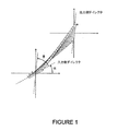
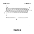
種々様々なLCD設計が存在する。図1を参照すると、設計者は、ラビング方向を選択することができるが、そのラビング方向は第1のガラス面に対して静止しているとき、すなわち各電極に対して電圧が印加されていないときに、液晶分子のダイレクタまたは分子軸が配向する方向である。第2のガラス面のラビング方向を適切に選択することにより、ねじれ角Φを制御することができる。図2を参照すると、液晶材料が充填されたガラスパネル間の間隔であるセルギャップdと、プレチルト角Θもまた制御することができるが、このプレチルトとは、液晶ダイレクタとガラス面との間の角度である。これらのセルパラメータを選択することに加えて、設計者はセルの外面に装着される偏光子の配向度、ならびに、液晶セルと偏光子との間に配置される複屈折フィルムを選択する。 There are a wide variety of LCD designs. Referring to FIG. 1, the designer can select a rubbing direction, but the rubbing direction is stationary with respect to the first glass surface, that is, no voltage is applied to each electrode. Sometimes it is the direction in which the directors or molecular axes of the liquid crystal molecules are aligned. The twist angle Φ can be controlled by appropriately selecting the rubbing direction of the second glass surface. Referring to FIG. 2, the cell gap d, which is the spacing between the glass panels filled with liquid crystal material, and the pretilt angle Θ can also be controlled, this pretilt being between the liquid crystal director and the glass surface. Is an angle. In addition to selecting these cell parameters, the designer selects the degree of orientation of the polarizer mounted on the outer surface of the cell, as well as the birefringent film placed between the liquid crystal cell and the polarizer.
一例として、一般的なLCD設計は、ねじれネマチック(TN)構成であり、そのネマチック構成において、ねじれ角(Φ)は90°となるように選択される。典型的なTN LCDは、8°のプレチルト角Θ、約5ミクロンのセルギャップdを有していることがある。他の設計としては、180度と270度の間のねじれ角を有する超ねじれネマチック(STN)モード、0°のねじれ角を有するIPS(in−plane switching)モードおよびOCB(optically compensated birefringence)モード、ならびに約90°のプレチルト角を有するVAN(vertically aligned nematic)モードがある。また、多くの他のモードが設計され、開発されてきた。これらの設計のそれぞれは、それぞれ特有の長所と短所を有している。ある設計は優れた視野角特性を有している一方で、他の設計は優れたスイッチング応答時間を有し、また他の設計は製造コストを最も低くすることができる。 As an example, a common LCD design is a twisted nematic (TN) configuration, in which the twist angle (Φ) is selected to be 90 °. A typical TN LCD may have a pretilt angle Θ of 8 ° and a cell gap d of about 5 microns. Other designs include a super twisted nematic (STN) mode with a twist angle between 180 and 270 degrees, an IPS (in-plane switching) mode with a twist angle of 0 °, and an optically compensated birefringence (OCB) mode, There is a VAN (vertically aligned nematic) mode having a pretilt angle of about 90 °. Many other modes have also been designed and developed. Each of these designs has its own advantages and disadvantages. Some designs have excellent viewing angle characteristics, while other designs have excellent switching response times, and other designs can have the lowest manufacturing costs.
セルまたはパネル設計にかかわらず、LCDの最終的な性能は、正しい値のラビング方向、ねじれ角、セルギャップおよびプレチルト角でセルを製造できるかに依存している。これらのパラメータの一部または全てを測定するための種々の技法および計測器が導入されてきた。しかしながら、これらの技法および計測器は多くの場合は緩慢なものであり、液晶セル上の単一の小さな場所を測定するために、時には約20秒〜30秒を要している。その結果として、製造する間にセル上のわずか5つの場所しか試験することができず、これらの場所とは、一般には中央および各コーナー領域となる。そのような測定では、ラビング方向のミスアライメント、セル厚さの不均一性および他の欠陥などのセル欠陥が検出される。 Regardless of the cell or panel design, the final performance of the LCD depends on the ability to manufacture the cell with the correct values of rubbing direction, twist angle, cell gap and pretilt angle. Various techniques and instruments have been introduced to measure some or all of these parameters. However, these techniques and instruments are often slow and sometimes require about 20-30 seconds to measure a single small location on a liquid crystal cell. As a result, only five locations on the cell can be tested during manufacturing, and these locations are typically the center and each corner area. Such measurements detect cell defects such as misalignment in the rubbing direction, cell thickness non-uniformity and other defects.
これらのパラメータを測定するための計測器は、LCDセルまたはパネルの製造および品質管理のための重要なツールであり、またさらには研究開発のための重要なツールである。上述した現行の測定装置および方法が低速であることから、製造中のセルのスループットが制限されていることは明白である。また、これらのパラメータを測定するための既存の計測器では、パラメータのうちのいくつかを先験的に知ることがしばしば必要となり、正確な測定値は限られた範囲の値で得られるに過ぎないことがある。例えば、既存の測定システムでは、セルのラビング方向を事前に知ることが必要になることがあり、また、プレチルト角を0度から30度の範囲でしか測定できないことがある。別の既存の測定システムでは、液晶分子における時計回りのねじれの向きと反時計回りのねじれの向きとを区別できないことがある。 Instruments for measuring these parameters are important tools for LCD cell or panel manufacturing and quality control, and even for research and development. Obviously, the current measuring devices and methods described above are slow, which limits the throughput of the cell being manufactured. Also, existing instruments for measuring these parameters often require a priori knowledge of some of the parameters, and accurate measurements can only be obtained with a limited range of values. There may not be. For example, in existing measurement systems, it may be necessary to know the rubbing direction of the cell in advance, and the pretilt angle may be measured only in the range of 0 to 30 degrees. Another existing measurement system may not be able to distinguish between clockwise and counterclockwise twist directions in liquid crystal molecules.
本出願人の発明は、いかなる液晶セルのラビング方向、ねじれ角、セルギャップおよびプレチルトも同時に測定することが可能である。また、本発明は、先行技術に対して際立った利点を有している。以下で説明するように、先行技術で説明される技法は、所望のパラメータのうちの一部分のみを測定するもの、または、セルの特定のモードに対してのみ有効であるもの、または、所望のパラメータのうちの一部を事前に知ることが必要となるもの、または、測定を完了するためにLCセルを回転させることが必要となるものである。本発明は、これらの制限を有していない。 Applicant's invention can simultaneously measure the rubbing direction, twist angle, cell gap and pretilt of any liquid crystal cell. The present invention also has significant advantages over the prior art. As described below, the techniques described in the prior art measure only some of the desired parameters, or are valid only for a specific mode of the cell, or the desired parameters Of these, it is necessary to know a part of them in advance, or it is necessary to rotate the LC cell to complete the measurement. The present invention does not have these limitations.
米国特許第5,239,365号に開示されている発明は、ねじれた液晶セルの厚さを測定するための技法を説明したものである。しかしながら、この技法では、ラビング方向およびねじれ角を先験的に知ることが必要となる。直線偏光子を適切な方向にアライメントすることによって、この技法は、スペクトル透過率の測定値からセルのリターダンスを決定することができ、次いで、液晶材料の既知の複屈折率Δnに基づいてセルギャップを計算することができる。この技法では、ねじれ角またはラビング方向を測定することはできない。 The invention disclosed in US Pat. No. 5,239,365 describes a technique for measuring the thickness of a twisted liquid crystal cell. However, this technique requires a priori knowledge of the rubbing direction and twist angle. By aligning the linear polarizer in the appropriate direction, this technique can determine the cell's retardance from the spectral transmission measurements, and then the cell based on the known birefringence Δn of the liquid crystal material. The gap can be calculated. With this technique, the twist angle or rubbing direction cannot be measured.
米国特許第5,532,823号に開示されている発明は、先行技術を改善したものである。交差させた偏光子を通じてスペクトル透過率を測定することによって、また偏光子間での液晶セルの連続的な回転を可能にすることによって、近似法を使用してねじれ角、ラビング方向およびセルギャップを測定している。この技法は、ねじれ角が120°未満であることを必要としており、したがって、STNモードセルの測定には使用することができない。 The invention disclosed in US Pat. No. 5,532,823 is an improvement over the prior art. By measuring spectral transmission through crossed polarizers and by allowing continuous rotation of the liquid crystal cell between the polarizers, the approximation method is used to determine the twist angle, rubbing direction and cell gap. Measuring. This technique requires the twist angle to be less than 120 ° and therefore cannot be used to measure STN mode cells.
さらなる改善が米国特許第6,081,337号に記載されている。この技法では、液晶セルは回転されない。その代わりに、スペクトル透過率の測定が行われている間、セルの前後の偏光子が回転される。2つの偏光子に対する適切な回転角度を決定し、かつラビング方向、ねじれ角およびセルギャップを決定することができるアルゴリズムが記載されている。 Further improvements are described in US Pat. No. 6,081,337. In this technique, the liquid crystal cell is not rotated. Instead, the polarizer before and after the cell is rotated while the spectral transmission measurement is being performed. An algorithm is described that can determine the appropriate rotation angle for the two polarizers and determine the rubbing direction, twist angle and cell gap.
上述した3つの技法のそれぞれは、サンプルを直線偏光状態で照明し、サンプルから出る光の直線偏光成分を解析することによって、液晶セルの特性を決定するものである。しかしながら、ねじれた液晶セルのキラル構造は、円形および楕円形の偏光状態を調査することによって、相当な量の付加的な情報を得ることができるような構造である。米国特許第6,300,954号では、液晶セルを出る光の完全な偏光状態(ストークスベクトル)を調べることの有用性が認められている。しかしながら、この技法は直線偏光をセルに放つに過ぎない。透過ビームにおける最大測定値または最小測定値を生じる配向度を見つけるために、セルが回転される。突き止められた配向度において、セルギャップおよびねじれ角を、測定したストークスベクトルから決定することができる。しかしながら、この新しい先行技術においても、測定のために液晶セルを回転させることが必要となり、また、ラビング方向は測定されない。 Each of the three techniques described above determines the characteristics of the liquid crystal cell by illuminating the sample in a linearly polarized state and analyzing the linearly polarized component of the light exiting the sample. However, the chiral structure of a twisted liquid crystal cell is such that a considerable amount of additional information can be obtained by investigating circular and elliptical polarization states. US Pat. No. 6,300,954 recognizes the utility of examining the complete polarization state (Stokes vector) of light exiting a liquid crystal cell. However, this technique only emits linearly polarized light into the cell. The cell is rotated to find the degree of orientation that produces the maximum or minimum measurement in the transmitted beam. At the determined degree of orientation, the cell gap and twist angle can be determined from the measured Stokes vectors. However, even in this new prior art, it is necessary to rotate the liquid crystal cell for measurement, and the rubbing direction is not measured.
液晶セルのセルギャップ、ねじれ角およびラビング方向を迅速かつ正確に測定するためには、セルの完全なミュラー行列を1つ以上の波長で測定すると有利であることを、本発明において示す。周知のことであるが、サンプルのミュラー行列を正確に測定するには、左回りの回転および右回りの回転を含めて、直線、楕円形および円形など、種々の偏光状態でサンプルを照明し、それらの偏光状態がサンプルと相互作用した後に、同様な種々の偏光状態を解析することが必要となる。測定が適切に実施された場合に、サンプルのミュラー行列を測定することができる。ミュラー行列は、リターダ特性、偏光子特性および偏光解消特性を含め、サンプルに生じうるすべての偏光変化特性を、ミュラー行列内に含んでいる。本発明に先立って、理論的なまたは測定された液晶セルのミュラー行列について記載された論文は、小数しか存在しない。 In order to quickly and accurately measure the cell gap, twist angle and rubbing direction of a liquid crystal cell, it is shown in the present invention that it is advantageous to measure the complete Mueller matrix of the cell at one or more wavelengths. As is well known, to accurately measure the sample Mueller matrix, illuminate the sample in various polarization states, including straight, oval and circular, including counterclockwise and clockwise rotations, After those polarization states interact with the sample, it is necessary to analyze various similar polarization states. If the measurements are properly performed, the sample Mueller matrix can be measured. The Mueller matrix includes in the Mueller matrix all polarization change characteristics that can occur in the sample, including retarder characteristics, polarizer characteristics and depolarization characteristics. Prior to the present invention, there are only a few papers describing the theoretical or measured Mueller matrix of a liquid crystal cell.
「J.Opt.Soc.Am.」(Vol.68、ページ1756〜1767、1979年)における記述では、ねじれネマチック液晶セルに対するミュラー行列を数学的に導出する方法が教示されている。しかしながら、さらなる分析は実現されておらず、また実験的結果は示されていない。「Appl.Opt.」(Vol.37、ページ937〜945、1998年)では、理論的にミュラー行列の偏光固有状態を計算することによって、ねじれネマチック液晶セルのミュラー行列の数学的導出が進められている。しかしながら、測定値は提示されておらず、この取組みの目的は、おそらく光学相関または他の光計算用途において使用するための位相のみの変調を、装置を使用して達成できるように、ねじれネマチック液晶セルの偏光固有状態を検出することであろう。本発明者らが知るところでは、ねじれネマチック液晶装置の測定した偏光固有状態を示す唯一の参考文献である「Opt.Lett.」(Vol.18、ページ1567〜1569、1993年)に記載された実験的測定の後に、その理論的な取組みは実際に続くものであった。これらの測定は、単一の波長でなされたものであり、また、液晶に印加した電圧の関数としてなされたものである。この取組みの目的は、光学相関用途のための位相のみの変調器として装置を使用することができるように、これらの固有状態を検出することであった。最後に、「Meas.Sci.Technol.」(Vol.12、ページ1938〜1948、2001年)において、本発明者らは、液晶セル上におけるミュラー行列測定の別の集合を見出しており、これは本発明者らが知るところでは唯一のものである。その記事において、強誘電性液晶セルの結晶非対称性およびスイッチング応答時間についての研究が、ミュラー行列測定を使用してなされている。 The description in “J. Opt. Soc. Am.” (Vol. 68, pages 1756-1767, 1979) teaches a method for mathematically deriving a Mueller matrix for twisted nematic liquid crystal cells. However, no further analysis has been realized and experimental results have not been shown. In "Appl. Opt." (Vol. 37, pages 937-945, 1998), the mathematical derivation of the Mueller matrix of a twisted nematic liquid crystal cell is advanced by calculating the polarization eigenstate of the Mueller matrix theoretically. ing. However, no measurements have been presented and the objective of this approach is to twist the nematic liquid crystal so that it can probably achieve phase-only modulation using the device for use in optical correlation or other optical computing applications. It would detect the polarization eigenstates of the cell. As we know, it is described in “Opt. Lett.” (Vol. 18, pages 1567-1569, 1993) which is the only reference showing the measured polarization eigenstates of twisted nematic liquid crystal devices. After experimental measurements, the theoretical approach actually followed. These measurements were made at a single wavelength and were made as a function of the voltage applied to the liquid crystal. The purpose of this effort was to detect these eigenstates so that the device could be used as a phase-only modulator for optical correlation applications. Finally, in “Meas. Sci. Technol.” (Vol. 12, pages 1938-1948, 2001), we have found another set of Mueller matrix measurements on liquid crystal cells. This is the only thing we know. In that article, studies on crystal asymmetry and switching response time of ferroelectric liquid crystal cells have been made using Mueller matrix measurements.
先行技術についての本発明者らの調査を要約すると、先行技術は2つのカテゴリに分類できることが分かる。その2つのカテゴリとは、すなわち液晶セルの物理的特性を測定するための方法および装置について記載した特許と、液晶セルのミュラー行列を理論的にモデル化するか、または実験的に測定した学術的研究論文である。特許される技法は、能力が限られた単純なシステムから、より多くの偏光特性を測定することができる複雑なシステムであり、したがって液晶セルのより多くのパラメータを測定することができるより複雑なシステムへと進化している。しかしながら、特許された技法には、完全な偏光特性、すなわち完全なミュラー行列測定に必要なシステムの複雑さの水準について主張したものは依然として存在しない。学術的研究論文については、液晶に対するミュラー行列がいかなるものであるかを導出するもの、または、液晶セルのミュラー行列を様々な研究目的で分析して測定するもののいずれかである。これらの論文の目的は、常にLCセルの光学特性を調査することであった。これらの論文では、問題を逆にすること、すなわち、測定した光学特性を使用して遡り、セルの物理的特性を判定することは考慮されていない。液晶セルのラビング方向、ねじれ角、セルギャップ、プレチルトを同時にかつ一意に決定するために完全なミュラー行列測定値を使用することを主張するこれらの論文のいずれも、実験的測定または理論的分析を提示していない。 Summarizing our investigation of the prior art, it can be seen that the prior art can be divided into two categories. The two categories are: patents describing methods and apparatus for measuring the physical properties of liquid crystal cells, and academic models that theoretically model or experimentally measure the Mueller matrix of liquid crystal cells. It is a research paper. The patented technique is a complex system that can measure more polarization properties from a simple system with limited capabilities, and thus more complex that can measure more parameters of a liquid crystal cell. It has evolved into a system. However, there is still no claim in the patented technique for perfect polarization properties, ie the level of system complexity required for complete Mueller matrix measurements. Academic research papers are either to derive what the Mueller matrix for the liquid crystal is or to analyze and measure the Mueller matrix of the liquid crystal cell for various research purposes. The purpose of these papers was always to investigate the optical properties of LC cells. These papers do not consider reversing the problem, ie, using the measured optical properties to go back and determining the physical properties of the cell. None of these papers claiming to use full Mueller matrix measurements to simultaneously and uniquely determine the rubbing direction, twist angle, cell gap, and pretilt of liquid crystal cells. Not presenting.
したがって、本発明の一つの目的は、セルギャップ、ねじれ角およびラビング方向を含むパラメータの1つ以上を、それらの値が予め知られていない場合でも正確に決定することができるような液晶セルのミュラー行列の測定方法を提供することである。本発明の別の目的は、セルのセルギャップ、ねじれ角およびラビング方向が予め知られていない場合に液晶セルの光学特性を測定するための測定装置、または測定中に液晶セルを回転させる必要のない測定装置を提供することである。 Accordingly, one object of the present invention is to provide a liquid crystal cell in which one or more of the parameters including cell gap, twist angle and rubbing direction can be accurately determined even if their values are not known in advance. It is to provide a method for measuring the Mueller matrix. Another object of the present invention is to provide a measuring device for measuring the optical properties of the liquid crystal cell when the cell gap, twist angle and rubbing direction of the cell are not known in advance, or the need to rotate the liquid crystal cell during the measurement. Is to provide no measuring device.
本発明の別の目的は、所望の値のセルギャップ、ねじれ角およびラビング方向を有する液晶装置を製造する方法である。 Another object of the present invention is a method of manufacturing a liquid crystal device having a desired value of cell gap, twist angle and rubbing direction.
本発明の別の目的は、液晶ダイレクタのプレチルトが、液晶装置への測定ビームの入射角を変化させることによって決定され、かつプレチルト角が0度から90度の任意の値を取りうるような液晶セルのミュラー行列の測定方法を提供することである。 Another object of the present invention is a liquid crystal in which the pretilt of the liquid crystal director is determined by changing the incident angle of the measurement beam to the liquid crystal device, and the pretilt angle can take any value from 0 to 90 degrees. It is to provide a method for measuring the Mueller matrix of a cell.
本発明の別の目的は、プレチルト角が0度から90度の任意の角度を取りうるような液晶セルの液晶ダイレクタのプレチルトを測定するための測定装置である。 Another object of the present invention is a measuring apparatus for measuring a pretilt of a liquid crystal director of a liquid crystal cell such that the pretilt angle can take an arbitrary angle of 0 to 90 degrees.
本発明の別の目的は、所望の値のプレチルト角を有する液晶装置を製造する方法である。 Another object of the present invention is a method of manufacturing a liquid crystal device having a desired pretilt angle.
本発明のさらなる目的は、以下の添付の明細書を読めば明らかとなろう。 Further objects of the present invention will become apparent upon reading the following accompanying specification.
液晶セルのミュラー行列を測定するために、種々の異なる偏光状態にされた光が液晶セルに向けられ、セルは、これらの偏光状態をセルの特性に従って変化させる。偏光感応検出システムが、セルから現れる偏光状態を分析する。ミュラー行列を正確に測定するためには、種々の偏光状態を含む生成された光入力と、測定された偏光状態とは、共にポアンカレ球の大部分のサンプルとならなければならない。すなわち、相当に異なる配向度、楕円率および掌性を有する種々の偏光状態を生成し、分析しなければならない。液晶セルのミュラー行列が測定されると、セルギャップ、ねじれ角およびラビング方向が決定される。3つのパラメータのすべてが予め知られていない場合には、複数の波長でミュラー行列の測定が必要であり、これらのパラメータは、シミュレーションと測定が可能な限り緊密に一致するまで、セルのコンピュータシミュレーションにおいて反復法で変更される。他の場合、例えば、ねじれ角およびラビング方向の値が事前に知られている場合には、単一の波長でのミュラー行列の測定は、セルギャップを決定するために十分なものとなる。 In order to measure the Mueller matrix of a liquid crystal cell, light in a variety of different polarization states is directed to the liquid crystal cell, and the cell changes these polarization states according to the characteristics of the cell. A polarization sensitive detection system analyzes the polarization state emerging from the cell. In order to accurately measure the Mueller matrix, the generated light input, including the various polarization states, and the measured polarization state must both be the majority sample of the Poincare sphere. That is, various polarization states having significantly different degrees of orientation, ellipticity and palmarity must be generated and analyzed. When the Mueller matrix of the liquid crystal cell is measured, the cell gap, twist angle and rubbing direction are determined. If all three parameters are not known in advance, measurements of the Mueller matrix at multiple wavelengths are required, and these parameters are calculated by computer simulation of the cell until the simulation and measurement match as closely as possible. In the iterative method. In other cases, for example, if the values of twist angle and rubbing direction are known a priori, the measurement of the Mueller matrix at a single wavelength will be sufficient to determine the cell gap.
上述の測定では、通常ほとんどの場合そうであるように、複屈折率Δnおよびプレチルト角Θが、測定に先立って知られていることが必要となる。プレチルトが正確には知られていない場合には、プレチルト角を測定できるようにすれば有利となる。 The above measurements require that the birefringence Δn and the pretilt angle Θ be known prior to the measurement, as is usually the case most of the time. If the pretilt is not known accurately, it would be advantageous to be able to measure the pretilt angle.
プレチルト角を測定するために、測定ビームの入力方向と入射角を変化させることが可能な機械的取付け具に加えて、上述したものと同じミュラー行列の測定技法が使用される。ミュラー行列を入射角の関数として測定することによって、また、これらの測定結果を解析表現またはコンピュータシミュレーションのいずれかと比較することによって、液晶のプレチルト角を決定することができる。 In order to measure the pretilt angle, the same Mueller matrix measurement technique as described above is used in addition to the mechanical fixture capable of changing the input direction and the incident angle of the measurement beam. The pretilt angle of the liquid crystal can be determined by measuring the Mueller matrix as a function of the angle of incidence and by comparing these measurement results with either an analytical representation or a computer simulation.
図3は、本発明の基本的要素を示す。偏光状態生成器10は、時間変動する偏光状態を有する光学ビーム12を発生させる。このビームは、サンプル14、この場合はLCDセルと相互作用して、ビーム12の偏光状態の一部またはすべてを変化させる。変化した偏光状態は、偏光状態分析器16によって分析される。偏光状態分析器16は、時間変動する一連の偏光状態を測定するが、また同時に、ビームを分割し、その分割したビームのそれぞれを、異なる各々の固定した偏光要素および検出器に通すことによって、不連続な数の一定の偏光状態を測定することもできる。偏光状態生成器10および偏光状態分析器16は、それぞれマイクロコントローラまたはパーソナルコンピュータなどのプロセッサ18によって制御されている。プロセッサ18は、偏光状態生成器10によって開始され、偏光状態分析器16によって測定された既知の偏光状態に基づいて、サンプルのミュラー行列(図8)を計算する。ミュラー行列が測定されると、プロセッサ18は、セルギャップ、ねじれ角、ラビング方向およびプレチルト角など、液晶セル14の所望のパラメータを計算して、製造プロセスの間の可能な限り早い時期に、欠陥品であるLCDセルを判定する。強調すべきこととしては、現在の技術水準の方法では20秒〜30秒が必要になるのが現状であるのに対して、本出願人の発明は、試験されるLCDセルの場所ごとに約1秒未満で規定のパラメータを迅速に決定する。そのような試験は、概して、完成したLCD視野スクリーンの色純度に関するものである。例えば、公称で5ミクロンのセルギャップが工場規格外に変動する場合、変動する領域には、白色または黒色のスクリーン上に、目立って明るいか、または暗い濃淡のついた領域が発生する。テレビまたはコンピュータスクリーン上で、そのような領域は、許容範囲外とされる目立った望ましくない色合いを有することがある。したがって、そのような欠陥セルを製造プロセスにおいて早期に識別して、そのセルを廃棄するか、または再利用できるようにすることが重要である。予想されるデッドピクセルの個数を判定するための電気試験など、LCDセルに対するさらなる試験が、後に製造プロセスにおいて実施される。制御器20、21は、本発明者の参照出願に記載されているように、偏光状態生成器10および偏光状態分析器16の回転速度を制御する。
FIG. 3 shows the basic elements of the present invention. The
図4は、本発明者によって発明されたミュラー行列測定システムの実現可能な一実施形態を示したものであり、上で参照した「Complete Polarimeter」と題した本発明者の特許出願に詳細に記載されている。この装置は、LCDセルの測定値を取得するために、適切に拡大・縮小して使用することができる。参照出願の装置に対する1つの考えられる修正は、サンプリング用のLCDセルを受けるために、X−Y方向への平行移動が可能となるテーブルを拡大することである。その時点の出願において、図3の偏光状態生成器10は、光源24によって生成された平行光学ビーム22をもたらすものとして示されており、その光ビームは、リターダンスの約3分の1波長で、水平な直線偏光子26を通り、次いで連続的に回転するリターダ28を通るように向けられている。本発明者の参照出願に記載されているように、この結果、時間変動する偏光状態の連続光が、サンプル30、すなわちLCDセルを通じて放出され、そのLCDセルは、適切に寸法決めされたX−Y方向に平行移動が可能なテーブルに装着され、セルの様々な場所を測定するために移動させることができるようになっている。図3の偏光状態分析器16は、約3分の1波長のリターダンスを有する連続的に回転するリターダ31を備えるように構築することができ、それに続いて水平直線偏光子32が設置され、その後に光検出器34が続いている。2つの回転するリターダ28、31は、完全には整数でない約5:1の比で回転しており、また、プロセッサ18はセルのミュラー行列を計算する。
FIG. 4 illustrates one possible embodiment of the Mueller matrix measurement system invented by the inventor and is described in detail in the inventor's patent application entitled “Complete Polarimeter” referenced above. Has been. This device can be used with appropriate enlargement / reduction to obtain LCD cell measurements. One possible modification to the device of the reference application is to enlarge the table that allows translation in the XY direction to receive the LCD cell for sampling. In the current application, the
図5は、本発明者の参照出願に提示されたシステムを概略的に示したものである。ここで、本発明者の偏光状態生成器10および偏光状態分析器16は、ロボット制御システム40に装着されており、そのロボット制御システム40は、平行光ビーム22の入射角度を最大で約80度変化させることが可能であり、その一方で偏光状態生成器10および偏光状態分析器16のアライメントを維持する。これはロボット制御システムによって容易にされたものであり、このロボット制御システムは、セル30を通って任意の角度方向にビーム22を向けることができるように、偏光状態生成器10および偏光状態分析器16を2軸システムに装着している。加えて、ロボット制御装置40は、直線平行移動器42を備えており、その直線平行移動器42は、セル30上の複数の場所を試験することができるように、ある方向にセル30を移動させる。
FIG. 5 schematically illustrates the system presented in the inventor's reference application. Here, the
本発明は、ミュラー行列の特定の集合を測定し、そのデータを使用して、セルギャップ、ねじれ角、ラビング方向およびプレチルト角などの液晶セル30における所望のパラメータを計算する付加的なステップを組み込んでいる。ミュラー行列のどの集合を測定するかの選択は、液晶パラメータのうちのどれが事前に知られているか、またはどれを測定すべきかに依存する。例えば、プレチルト角は多くの場合既知であり、この場合にはミュラー行列を1つ以上の波長において垂直入射で測定すると、セルギャップ、ねじれ角およびラビング方向を計算するために十分なデータが得られる。別の例としては、ねじれ角はしばしばゼロであることが知られている。この場合にはプレチルトおよびセルギャップは、ミュラー行列を入射角の関数として測定することによって決定することができ、ここで、入射平面は、液晶ダイレクタに沿うように選択されるか、または液晶ダイレクタに対して垂直となるように選択される。液晶セルについての情報が既知でない場合には、セルパラメータのすべてを決定するために、1つ以上の波長および1つ以上の角度でミュラー行列を測定することができる。いかなる場合においても、測定したミュラー行列から液晶セルパラメータを計算するための技法は同じであり、また以下で説明するとおりである。
The present invention incorporates additional steps to measure a specific set of Mueller matrices and use that data to calculate desired parameters in the
液晶セルのパラメータを決定するために、測定されたミュラー行列は、セルの数学的モデル(コンピュータシミュレーション)と比較されるが、ここで、そのモデルは、ラビング方向、ねじれ角、セルギャップおよびプレチルト角の自由パラメータを有している。通常、液晶材料の複屈折率Δnは、波長の関数として既に知られている。複屈折率を1つの波長でのみ知られることは可能であり、また波長分散もモデルにおいて自由パラメータであることは可能である。 In order to determine the parameters of the liquid crystal cell, the measured Mueller matrix is compared with a mathematical model of the cell (computer simulation), where the rubbing direction, twist angle, cell gap and pretilt angle. Have free parameters. Usually, the birefringence Δn of the liquid crystal material is already known as a function of wavelength. It is possible for the birefringence to be known only at one wavelength, and chromatic dispersion can also be a free parameter in the model.
この数学的モデルを作成するために、液晶セルは1軸複屈折材料のQ枚の個別均質層としてモデル化され、Qは50などの大きな数である。大きなねじれ角を有するか、またはその他に必要とされ、または望まれる場合の液晶セルに対して、多数の層、例えば約400枚の層が、シミュレーションの精度を向上させるために、使用されるか、または必要とされる場合がある。各複屈折層は、それぞれ通常の屈折率と異常な屈折率である既知の値neおよびnoを有する1軸材料としてモデル化される。屈折率楕円体の異常軸は、各個別の層ごとに液晶分子のダイレクタに沿って整列している。セルのガラスパネルと接触する層1と層Qの場合、ダイレクタは、垂直線に対してセルのプレチルト角だけ傾斜している。層1の場合、xy平面におけるダイレクタの配向度は、ラビング方向によって与えられる。層Qの場合、xy平面におけるダイレクタの配向度は、層1のラビング方向にねじれ角を加えたものによって与えられる。層2から層Q−1の場合、チルト角および配向度は、層1から層Qへと線形に変化するようにモデル化され、このモデル化は液晶セルに印加された電圧がないときには有効な想定となる。有効な想定となる理由としては、このモデル化が、液晶分子の最低自由エネルギー構成または静止状態を近似したものであるからである。さらに他にも、より正確な数学的モデルが望まれるか、または要求される場合には、チルト角および配向度の線形な変化を、液晶分子の弾性定数のような既知の方式で変動する数学的シミュレーションの結果で置き換えることができる。そのようなシミュレーションでは、シミュレートされる液晶材料の非線形な側面が考慮される。弾性連続体理論は、液晶分子の最低自由エネルギー構成を決定するそのような手段に基づいている。弾性連続体理論のモデルを使用すると、シミュレーションの精度が向上するが、必要となる計算時間もまた増加する。
In order to create this mathematical model, the liquid crystal cell is modeled as Q individual homogeneous layers of uniaxial birefringent material, where Q is a large number such as 50. Whether a large number of layers, for example about 400 layers, are used to improve the accuracy of the simulation for a liquid crystal cell with a large twist angle or otherwise needed or desired Or may be required. Each birefringent layer is modeled as a uniaxial material having a known value n e and n o is the ordinary refractive index, respectively and abnormal refractive index. The extraordinary axis of the refractive index ellipsoid is aligned along the director of the liquid crystal molecules for each individual layer. In the case of
このモデルについて説明するために、図1、図6aおよび図6bを参照されたい。図1に示す事例では、1〜22(Q=22)で示す22枚の層を示しており、プレチルトはゼロであり、層1におけるダイレクタ配向度はαであり、またその配向度は層Qにおいて角度α+φへと線形に変動している。図6において、2つの事例を示しているが、Q=22であり、層1および層Qにおける配向度は同じ角度Θであり、またねじれ角はゼロである。図6の上側の図は、このセルの「広がり」モードを示し、図6の下側の図は、このセルの「曲げ」モードを示す。これらのモード間の差異は、チルト角がセルを通じて線形に増加するか、または線形に減少するかである。双方のモードは、液晶セル製造業者によって物理的に実現可能であり、いずれのモードもモデル化することができる。
To illustrate this model, please refer to FIGS. 1, 6a and 6b. In the example shown in FIG. 1, 22 layers indicated by 1 to 22 (Q = 22) are shown, the pretilt is zero, the director orientation degree in
このモデルを実現するために、各層のミュラー行列が、既知の光学波長、光の既知の伝播方向、液晶材料の既知の複屈折率ならびにプレチルト、ラビング方向、セルギャップおよびねじれ角の推定値に基づいて計算される。Q個の個別のミュラー行列が計算されると、セルの全体的なミュラー行列が以下のように計算される。 To achieve this model, each layer's Mueller matrix is based on known optical wavelengths, known propagation directions of light, known birefringence of liquid crystal materials and estimates of pretilt, rubbing direction, cell gap and twist angle. Is calculated. Once Q individual Mueller matrices are computed, the overall Mueller matrix for the cell is computed as follows:
Mcell=MQMQ−1...M2M1
上式において、Mcellは、測定したデータセットにおいて各光学波長または入射方向ごとに計算される。次いで、モデル化された点と測定された点との間の達成可能な最低の二乗平均差を用いて、モデル化されたミュラー行列が測定されたミュラー行列と一致するまで、プレチルト、ラビング方向、セルギャップおよびねじれ角の推定値を反復法で修正する。当業者には周知であるが、ガウス−ニュートン法、勾配降下法またはレーベンバーグ−マルカートアルゴリズムなど、任意の標準的な最適化アルゴリズムがこの目的に適したものとなる。
M cell = M Q M Q-1 . . . M 2 M 1
In the above equation, M cell is calculated for each optical wavelength or incident direction in the measured data set. Then, using the lowest achievable mean square difference between the modeled point and the measured point, pretilt, rubbing direction, until the modeled Mueller matrix matches the measured Mueller matrix, The cell gap and twist angle estimates are modified iteratively. As is well known to those skilled in the art, any standard optimization algorithm, such as the Gauss-Newton method, gradient descent method or Levenberg-Marquardt algorithm, is suitable for this purpose.
図7は、液晶セルパラメータを決定するために必要なプロセスの流れ図である。ここで、ステップ50において、光源24が通電され、リターダ28、31の回転が開始する。信号は、処理用のコンピュータ18によって光検出器34から取得される。
FIG. 7 is a flow diagram of the process required to determine the liquid crystal cell parameters. Here, in
ステップ52において、サンプルを必要に応じて複数の波長で取得することができる。複数の波長におけるデータの生成は、複数の方式で達成することができる。例えば、光源24は、複数の狭帯域干渉フィルターを含む電動式フィルターホイールをさらに付加したハロゲン電球またはアークランプなどの白色光源であってもよい。これらのスペクトルフィルターは、典型的にはコンピュータまたは制御器の制御下で、プロセッサ18からRS−232ポートを介してフィルターホイールにコマンドを発行することによって、個別に選択することができる。別の方法として、光源24は、プロセッサ18からコマンドを発行することによっていかなる波長も選択可能となるモノクロメーターをさらに加えた白色光源から構成されていてもよい。また別の方法として、光源24は、白色光源から構成されていてもよく、また光検出器34はスペクトロメーターから構成されていてもよい。
In
ステップ54において、複数の入射角をサンプリング用に選択することができる。これらの入射角は、適切なコマンドをロボット取付け具40に送信するプロセッサ18によって生成される。
In
ステップ56において、測定されたミュラー行列が計算される。測定された1つのミュラー行列が、各波長および入射角の設定ごとに決定される。これらは、測定されているセルを表すミュラー行列である。
In
ステップ58において、セルギャップ、ねじれ角、ラビング方向およびプレチルトの初期推定値に基づいて、シミュレートされたミュラー行列を計算するためのコンピュータシミュレーションが実施される。シミュレートされた1つのミュラー行列は、測定された各波長および入射角ごとに計算される。すなわち、サンプルから測定された各ミュラー行列は、対応する1つのシミュレートされたミュラー行列を有する。ステップ60において、セルギャップ、ねじれ角、ラビング方向およびプレチルトの1つ以上の初期推量値が、反復法で変更される。反復のたびに、シミュレートされた新たなミュラー行列が計算され、次いで、測定されたミュラー行列と比較される。シミュレートされたミュラー行列の要素と測定されたミュラー行列の要素との間の二乗平均差は、最適化手法において効果尺度として使用される。シミュレートされたミュラー行列内の推定されるセルパラメータは、二乗平均差が最小化されるまで、または、二乗平均差が一般に試験中のLCDセルと緊密に適合することを示す十分に低い値に達するまで、反復法で変更される。反復法のステップ幅を選択するための技法、または最適化プロセスが解に収束する速度を最大化するための技法は、当業者には周知である。例えば、ガウス−ニュートン法、勾配降下法およびレーベンバーグ−マルカートアルゴリズムは、すべてこの目的に適している。セルギャップ、ねじれ角、ラビング方向およびプレチルトに対する最適化された値が分かると、ステップ62においてその値がユーザーに報告される。
In
モデル化されたデータを測定されたミュラー行列に適合させるとき、正規化されたミュラー行列における下方の3×3の小行列の値を適合させると有利である。正規化されたミュラー行列を使用すると、色フィルターまたはセルの他の分光特性の影響が計算から除去される。下方の3×3の小行列は、ミュラー行列のリターダンス情報を含んでおり、液晶装置は典型的にはリターダンスのみの装置である。0°以外の入射角において、ガラスセルのs反射率およびp反射率によって幾分かの非減衰性が発生する。すなわち、セルは部分的偏光子としても機能する。この場合、ミュラー行列の極分解を実施し、純粋なリターダンスのミュラー行列に対してのみ曲線適合を実施すると有利である。 When fitting the modeled data to the measured Mueller matrix, it is advantageous to fit the values of the lower 3 × 3 submatrix in the normalized Mueller matrix. Using a normalized Mueller matrix removes the effects of color filters or other spectral properties of the cell from the calculation. The lower 3 × 3 submatrix contains the Mueller matrix retardance information and the liquid crystal device is typically a retardance only device. At angles of incidence other than 0 °, some non-attenuation occurs due to the s reflectivity and p reflectivity of the glass cell. That is, the cell also functions as a partial polarizer. In this case, it is advantageous to perform polar decomposition of the Mueller matrix and to perform curve fitting only for the pure retardance Mueller matrix.
図8は、ねじれネマチックタイプの液晶セルに対する正規化されたミュラー行列の成分を示すグラフである。ミュラー行列の要素は、波長の関数として滑らかに変化している。最も一般的な場合、リターダンス次数は複数の次数にわたるが、その場合にも、ミュラー行列要素は滑らかに振る舞い、不連続性を有することがなく、ミュラー行列要素は曲線適合に最も適したものとなっている。 FIG. 8 is a graph showing normalized Mueller matrix components for a twisted nematic type liquid crystal cell. The elements of the Mueller matrix change smoothly as a function of wavelength. In the most general case, the retardance order spans multiple orders, but again, the Mueller matrix elements behave smoothly, have no discontinuities, and the Mueller matrix elements are best suited for curve fitting. It has become.
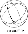
図9aおよび図9bは、図8に示すものと同じデータを示したものであるが、図9aはリターダンスの大きさを示し、図9bは図8のミュラー行列の固有解析を通じて計算されたリターダンスの速い軸を示している。当業者には周知であるが、計算されたリターダンスおよび速い軸は、リターダンスの大きさがリターダンスのさらなる180°を超えるたびに不連続性を有する。リターダンスの真の「次数」を各点で決定することが必要となり、プロットが連続的となるように大きさと速い軸を広げるように試みるアルゴリズムを適用することが必要となっている。実際に、図9aおよび図9bにおけるデータは、リターダンスが680nm以下の波長で180°を超えることから分かるように、既に広げられている。図9aおよび図9bは、液晶装置の挙動を理解して視覚化することを支援する上で非常に有用であるが、実際に曲線適合を行うにはあまり有用ではない。 9a and 9b show the same data as shown in FIG. 8, but FIG. 9a shows the magnitude of the retardance and FIG. 9b shows the retard calculated through eigenanalysis of the Mueller matrix of FIG. It shows the fast axis of dance. As is well known to those skilled in the art, the calculated retardance and fast axis have a discontinuity whenever the magnitude of the retardance exceeds an additional 180 ° of the retardance. It is necessary to determine the true “order” of retardance at each point, and it is necessary to apply an algorithm that attempts to widen the magnitude and fast axes so that the plot is continuous. In fact, the data in FIGS. 9a and 9b have already been expanded, as can be seen from the fact that the retardance exceeds 180 ° at wavelengths below 680 nm. 9a and 9b are very useful in assisting in understanding and visualizing the behavior of the liquid crystal device, but are not very useful in performing curve fitting in practice.
図10は、本発明を制御するために、また結果として得られたデータを解釈するために、研究者が研究開発環境において使用しうる1つの実現可能なグラフィカルユーザーインターフェースの一例を示す。ここでは、ポアンカレ球およびリターダンス対波長のグラフ表示が、研究者に提示されている。セルギャップ、ブラシ角、ねじれ角、プレチルトおよび入射角に対するスライダによって、様々なセルパラメータを個別に操作することができる。加えて、垂直スライダおよび水平スライダによって、ポアンカレ球が都合のよい向きから見えるように、そのポアンカレ球を操作することが可能となっている。セルパラメータのそのような操作は、シミュレートされた偏光特性と測定された偏光特性とを比較するために有用である。加えて、CALCULATE(計算)ボタンを押すと、測定されたミュラー行列データに基づいて、最良の適合セルパラメータを決定するための最適化ルーチンを開始することができる。 FIG. 10 shows an example of one possible graphical user interface that a researcher can use in a research and development environment to control the present invention and to interpret the resulting data. Here, the Poincare sphere and a graphical representation of retardance versus wavelength are presented to the researcher. Various cell parameters can be individually manipulated by sliders for cell gap, brush angle, twist angle, pretilt and incident angle. In addition, the Poincare sphere can be operated by the vertical slider and the horizontal slider so that the Poincare sphere can be seen from a convenient direction. Such manipulation of cell parameters is useful for comparing simulated and measured polarization characteristics. In addition, pressing the CALCULATE button can initiate an optimization routine for determining the best fit cell parameters based on the measured Mueller matrix data.
技術者または他の作業者が、アセンブリラインの方式で複数のセルに対して同じ測定を繰り返し行う製造環境においては、図11に示すような簡略化されたインターフェースがおそらくは好ましいものとなるであろう。ここでは、ポインティングデバイスのボタンを一度クリックするか、またはタッチスクリーンなどを一度タッチすると、すべての測定を実施することができる。「Perform Single Measurement(一回の測定を実施)」ボタンを押すと、セルギャップ、ラビング方向、ねじれ角およびプレチルトの値が自動的に測定されて表示される。この測定は、予め定義された「レシピ」に基づいていてもよい。そのようなレシピは、どのようなチルト角、光学波長およびセル位置が測定されるべきかを示すことができ、また、測定されたパラメータが記憶されるデータベースを指定することができる。セルパラメータの1つ以上が事前に知られており、したがって測定する必要がない場合には、それらのパラメータを入力することができ、次いで最適化ルーチンから除外することができる。強調すべきこととしては、パラメータのいずれも事前に知られていない場合には、パラメータのすべてを計算できるようにするために、十分な波長および入射角で測定するようにシステムをプログラムすることができる。また、インターフェースは、オペレータがセル上の特定のXY位置を測定するか、または自動化されたXYマップ測定を実施するためのボタンを備えていてもよい。 In a manufacturing environment where technicians or other workers repeatedly perform the same measurements on multiple cells in an assembly line fashion, a simplified interface as shown in FIG. 11 will probably be preferred. . Here, all the measurements can be performed by clicking once on the button of the pointing device or once touching the touch screen or the like. When the “Perform Single Measurement” button is pressed, the cell gap, rubbing direction, twist angle and pretilt values are automatically measured and displayed. This measurement may be based on a predefined “recipe”. Such a recipe can indicate what tilt angle, optical wavelength and cell position are to be measured, and can specify a database in which the measured parameters are stored. If one or more of the cell parameters are known in advance and therefore do not need to be measured, those parameters can be entered and then excluded from the optimization routine. It should be emphasized that if none of the parameters are known in advance, the system can be programmed to measure at a sufficient wavelength and angle of incidence so that all of the parameters can be calculated. it can. The interface may also include buttons for an operator to measure a specific XY position on the cell or to perform automated XY map measurements.
留意すべきこととして、本発明者は、本願を通じて液晶セルの物理的パラメータを以下のステップによって決定する技法について説明している。そのステップとは、すなわち一連の様々な偏光状態が液晶セルを通じて向けられるステップ、次いで変化した偏光状態が偏光状態分析器を通過するステップ、分析された各偏光状態における光出力が光検出器で測定されるステップ、液晶セルのミュラー行列が測定された光出力、および生成され分析された既知の偏光状態から計算されるステップ、ミュラー行列の測定が1つ以上の光学波長および1つ以上の入射ビーム方向でなされるステップ、液晶セルのミュラー行列のコンピュータシミュレーションが同じ光学波長および入射ビーム方向に対して展開されるステップ、シミュレートされたミュラー行列と測定されたミュラー行列との二乗平均差が最小化されるまでコンピュータシミュレーションのパラメータが反復法によって変更されるステップ、結果として生じたコンピュータシミュレーションの最終的パラメータが液晶セルの真のパラメータ(セルギャップ、ラビング方向、ねじれ角、プレチルト角)を表すステップである。これらのステップは、幾分か修正するかまたは再編成することができ、また依然として本発明の範囲内に含まれることが、当業者には明らかとなるであろう。例えば、測定された光出力をミュラー行列に変換するステップを除去し、光検出器によって測定される光出力をシミュレートするステップをさらにコンピュータシミュレーションに追加し、次いで、ミュラー行列を直接比較する代わりに、シミュレートされた光出力と測定された光出力との二乗平均差を最小化するように、コンピュータシミュレーションのパラメータを反復法で変更することによって、厳密に同じ結果を実現することも可能である。別の方法として、ミュラー行列間の二乗平均差の代わりに、ピーク差を最小化することを選択して、同様の結果を達成してもよい。 It should be noted that the inventor has described a technique for determining the physical parameters of a liquid crystal cell by the following steps throughout the application. That is, a step in which a series of different polarization states are directed through the liquid crystal cell, then the changed polarization state passes through a polarization state analyzer, and the light output at each analyzed polarization state is measured with a photodetector. A step in which the Mueller matrix of the liquid crystal cell is measured and calculated from the known polarization state generated and analyzed, the measurement of the Mueller matrix is one or more optical wavelengths and one or more incident beams The steps taken in the direction, the computer simulation of the liquid crystal cell Mueller matrix is developed for the same optical wavelength and incident beam direction, the root mean square difference between the simulated Mueller matrix and the measured Mueller matrix is minimized Computer simulation parameters are changed iteratively until Step, the final parameters of the computer simulation resulting is a step of representing the true parameters of the liquid crystal cell (cell gap, rubbing direction, twist angle, pre-tilt angle). It will be apparent to those skilled in the art that these steps can be somewhat modified or rearranged and still fall within the scope of the present invention. For example, instead of removing the step of converting the measured light output into a Mueller matrix, adding the step of simulating the light output measured by the photodetector to a computer simulation, then instead of directly comparing the Mueller matrices It is also possible to achieve exactly the same result by iteratively changing the parameters of the computer simulation to minimize the root mean square difference between the simulated light output and the measured light output . Alternatively, instead of square mean differences between Mueller matrices, one may choose to minimize peak differences to achieve similar results.
また、留意してもらいたいこととして、本発明者は、本願を通じてサンプルセルのミュラー行列について論じてきた。論じてきたすべては、サンプルのジョーンズ行列を測定するシステムにも等しく有効である。偏光解消効果を示さないサンプルの場合には、ミュラー行列とジョーンズ行列との間に1対1の関係(任意にジョーンズ行列へと乗算されうる絶対位相項より小さい)が存在する。一般に、ミュラー行列は、実験的な取組みによって有利であるが、それは、ミュラー行列が偏光解消効果を含むこともでき、また、ジョーンズ行列に存在する未定の絶対位相項を有していないからである。それにもかかわらず、測定されたジョーンズ行列をミュラー行列の代わりに使用する技法は、本発明の別の実施形態となる。 It should also be noted that the present inventor has discussed the Mueller matrix of the sample cell throughout this application. All that has been discussed is equally valid for a system that measures the Jones matrix of a sample. For samples that do not exhibit the depolarization effect, there is a one-to-one relationship between the Mueller matrix and the Jones matrix (which is less than the absolute phase term that can optionally be multiplied into the Jones matrix). In general, the Mueller matrix is advantageous due to experimental efforts, because the Mueller matrix can also include a depolarizing effect and does not have an undetermined absolute phase term present in the Jones matrix. . Nevertheless, the technique of using the measured Jones matrix instead of the Mueller matrix is another embodiment of the present invention.
最後に、留意してもらいたいこととして、実施可能な液晶のコンピュータシミュレーションに対するいくつかのわずかな変更形態で本発明の範囲に含まれるものが存在する。ゼロでない入射角における液晶セルのミュラー行列を計算するときに、液晶セルのガラスプレートの部分偏光効果は、フレネル反射係数に基づいてモデル化することができ、次いでこれらのシミュレートされたミュラー行列は、上述のように測定されたミュラー行列と比較される。これによって前述と同じ結果が得られるが、ここで、モデルは、ゼロでない入射角におけるフレネル反射係数を無視しており、また測定されたミュラー行列の極分解が実施され、その結果、測定されたミュラー行列の純粋なリターダンスの部分が、シミュレートされたミュラー行列と比較される。 Finally, it should be noted that there are several minor modifications to the liquid crystal computer simulation that can be implemented that are within the scope of the present invention. When calculating the Mueller matrix of a liquid crystal cell at a non-zero angle of incidence, the partial polarization effect of the glass plate of the liquid crystal cell can be modeled based on the Fresnel reflection coefficient, and then these simulated Mueller matrices are , Compared to the Mueller matrix measured as described above. This gives the same result as above, but the model ignores the Fresnel reflection coefficient at a non-zero angle of incidence, and a polar decomposition of the measured Mueller matrix is performed, resulting in a measurement. The pure retardance part of the Mueller matrix is compared with the simulated Mueller matrix.
今日使用されている3GHzを超える速度、64ビットプロセッサ、デュアルコアプロセッサなどを有するコンピュータでは、LCDセルに関連するパラメータを決定し、これらの計算されたパラメータをコンピュータモデルと比較するためのミュラー行列の計算は、非常に迅速なものとなっている。1秒当たり5,000個超のシミュレートされたLCDミュラー行列の計算を合理的に達成することができる。説明したように、そのようなモデル化および計算は、約1秒未満で達成することができ、試験時間が約2〜3分から数秒へと短縮され、試験プロセスのスループットが大いに向上している。 For computers with speeds in excess of 3 GHz, 64-bit processors, dual-core processors, etc., used today, the Mueller matrix for determining the parameters associated with the LCD cell and comparing these calculated parameters with the computer model The calculation is very quick. The calculation of more than 5,000 simulated LCD Mueller matrices per second can be reasonably achieved. As explained, such modeling and calculation can be accomplished in less than about 1 second, reducing test time from about 2-3 minutes to a few seconds, greatly improving the throughput of the test process.
このように、本発明者の発明およびその発明の使用方式について説明してきたので、添付した特許請求の範囲の範疇に正当に含まれる二次的な変更が、本発明者の発明およびその発明の使用方式に対して行われることは、当業者には明らかであろう。 As described above, the present inventors' invention and the mode of use of the invention have been described, so that secondary changes that are legitimately included in the scope of the appended claims can be considered as the invention's invention and the invention's invention. It will be apparent to those skilled in the art what is done for the mode of use.
Claims (31)
A)複数の偏光状態の各偏光状態が該複数の偏光状態の他の偏光状態とは異なる向き、楕円率および掌性を有するような複数の偏光状態を有する光ビームを、前記試験中の液晶セルを通じて送出し、
B)前記複数の偏光状態が前記試験中の液晶セルを通過した後に、送出された前記複数の偏光状態に沿った選択されたポイントにおいて、前記試験中の液晶セルによって変化させられた偏光状態を測定し、測定された偏光状態を該測定された偏光状態を表す前記データに変換し、
C)コンピュータ処理装置において、前記試験中の液晶セルの少なくとも1つの推定された物理的パラメータに基づくモデル化された偏光特性を含んだ液晶セルモデルを作成し、
D)前記測定された偏光状態を表す前記データを使って、前記モデル化された偏光特性と前記試験中の液晶セルの偏光特性との間に緊密な適合が得られるまで、前記コンピュータモデルを調整し、
E)これにより前記緊密な適合が得られたときには、前記液晶セルモデルの前記少なくとも1つの推定された物理的パラメータが、前記試験中の液晶セルの対応する前記物理的パラメータを示すこと、
からなる方法。A method for using a computer processing device to analyze data representative of a measured polarization state of a liquid crystal cell under test to determine at least one physical parameter of the liquid crystal cell under test comprising:
A) A light beam having a plurality of polarization states such that each polarization state of the plurality of polarization states has a different orientation , ellipticity, and palmality from the other polarization states of the plurality of polarization states. Send through the cell,
B) After the plurality of polarization states have passed through the liquid crystal cell under test, the polarization state changed by the liquid crystal cell under test at a selected point along the plurality of polarization states sent out. Measuring and converting the measured polarization state into the data representing the measured polarization state;
C) In a computer processing device, creating a liquid crystal cell model including modeled polarization characteristics based on at least one estimated physical parameter of the liquid crystal cell under test,
D) using the data representing the measured polarization state to adjust the computer model until a close match is obtained between the modeled polarization characteristics and the polarization characteristics of the liquid crystal cell under test And
E) when this provides a close fit, the at least one estimated physical parameter of the liquid crystal cell model indicates the corresponding physical parameter of the liquid crystal cell under test;
A method consisting of:
異なる向き、楕円率および掌性を有する前記複数の偏光状態が前記液晶セルを通じて送出されるところの入射角、該入射角の方向、または該入射角と該入射角の方向の両方を変化させること、からさらになる方法。The method of claim 1, wherein said D) is:
Changing the incident angle, the direction of the incident angle, or both the incident angle and the direction of the incident angle, where the plurality of polarization states having different orientations , ellipticity and palmarity are transmitted through the liquid crystal cell; , A method that further consists of.
A)前記試験中の液晶セルの偏光特性を測定し、測定された前記偏光特性を前記試験中の液晶セルの前記測定された偏光特性を表す信号に変換し、
B)前記コンピュータプロセッサにおいて、前記試験中の液晶セルをモデル化するのに推定された物理的パラメータを使う、液晶セルの数学的モデルを作成し、
C)前記試験中の液晶セルの前記測定された偏光特性を表す前記信号を使って、前記液晶セルの数学的モデルの偏光特性と前記試験中の液晶セルの前記測定された偏光特性との間に緊密な適合が得られるまで、前記液晶セルの数学的モデル中の値を調整し、
D)前記試験中の液晶セルに緊密に適合した前記液晶セルの数学的モデルの前記推定された物理的パラメータに基づく、前記試験中の液晶セルの品質の表示を提供することを備え、
前記A)は、各々が十分に異なる向き、楕円率および掌性を有する十分な数の時間変動する偏光状態を送出して分析し、前記試験中の液晶セルを通じてポアンカレ球の大部分を覆うようにすること、からなる方法。 A method for using a computer processor to determine physical parameters of a liquid crystal cell, comprising:
A) measuring the polarization characteristics of the liquid crystal cell under test, and converting the measured polarization characteristics into a signal representing the measured polarization characteristics of the liquid crystal cell under test;
B) creating a mathematical model of the liquid crystal cell in the computer processor that uses the estimated physical parameters to model the liquid crystal cell under test;
C) Using the signal representing the measured polarization characteristics of the liquid crystal cell under test, between the polarization characteristics of the mathematical model of the liquid crystal cell and the measured polarization characteristics of the liquid crystal cell under test. Adjust the value in the mathematical model of the liquid crystal cell until a close fit is obtained,
D) providing an indication of the quality of the liquid crystal cell under test based on the estimated physical parameters of a mathematical model of the liquid crystal cell closely matched to the liquid crystal cell under test ;
A) sends and analyzes a sufficient number of time-varying polarization states, each with a sufficiently different orientation, ellipticity and palmality, to cover most of the Poincare sphere through the liquid crystal cell under test. A method consisting of.
各層の通常および異常な屈折率について既知の値をもった1軸複屈折材料の複数の均質層であって、該層の配向度およびチルトは既知のやり方で変化するものとして、前記液晶セルをモデル化し、
前記均質層の各層について偏光行列を計算し、
前記複数の均質層のそれぞれから作成された複数の偏光行列から、前記数学的モデルについての合成偏光行列を式
Mcell=MQ・MQ−1・...・M2・M1
を使って計算すること
からさらになる方法。12. The method of claim 11 , wherein B) is
The liquid crystal cell is defined as a plurality of homogeneous layers of uniaxial birefringent material with known values for the normal and extraordinary refractive indices of each layer, the degree of orientation and tilt of the layers changing in a known manner Model,
Calculating a polarization matrix for each layer of the homogeneous layer;
From a plurality of polarization matrices created from each of the plurality of homogeneous layers, a composite polarization matrix for the mathematical model is expressed by the equation M cell = M Q · M Q−1 . . .・ M 2・ M 1
A further method that consists of calculating with.
A)一連の偏光状態の各偏光状態が該一連の偏光状態の他の偏光状態とは向き、楕円率および掌性において異なるような、偏光状態生成器によって生成された一連の偏光状態を前記試験中の液晶セルに向け、
B)前記試験中の液晶セルによって変更された前記一連の偏光状態を偏光状態分析器によって分析し、分析された前記一連の偏光状態を対応する一連の電気信号に変換し、
C)前記コンピュータプロセッサを使って、前記一連の電気信号から前記試験中の液晶セルの偏光特性を計算し、
D)前記コンピュータを使って、前記試験中の液晶セルの少なくとも1つの推定された物理的パラメータを含んだコンピュータモデルを作成し、前記試験中の液晶セルの分析された前記変更特性と前記液晶セルのコンピュータモデルの計算された前記偏光特性との間に緊密な適合が得られるまで、前記少なくとも1つの推定された物理的パラメータを調整し、
E)前記試験中の液晶セルの対応する物理的パラメータを表す緊密に適合した前記推定された物理的パラメータの少なくとも1つの表示を提供すること、
からなる方法。A method for utilizing a computer processor to determine at least one physical parameter of a liquid crystal cell under test to determine whether the liquid crystal cell under test is defective, comprising:
A) The test of a series of polarization states generated by a polarization state generator such that each polarization state of a series of polarization states differs in orientation , ellipticity and palmality from the other polarization states of the series of polarization states. For the liquid crystal cell inside,
B) analyzing the series of polarization states modified by the liquid crystal cell under test by means of a polarization state analyzer and converting the analyzed series of polarization states into a corresponding series of electrical signals;
C) using the computer processor to calculate the polarization characteristics of the liquid crystal cell under test from the series of electrical signals;
D) using the computer to create a computer model that includes at least one estimated physical parameter of the liquid crystal cell under test, and analyzing the modified characteristics of the liquid crystal cell under test and the liquid crystal cell up tight fit is obtained between the calculated the polarization characteristics of the computer model to adjust the both the least is one estimated physical parameters,
E) Providing at least one display of the estimated physical parameters closely matched representing the corresponding physical parameters of the liquid crystal cell under test;
A method consisting of:
前記一連の偏光状態から複数の偏光行列を計算し、
前記試験中の液晶セルの偏光特性を示す合成偏光行列を、前記複数の偏光行列から作成すること、
からさらになる方法。The method of claim 17 , comprising:
Calculating a plurality of polarization matrices from the series of polarization states;
Creating a composite polarization matrix indicating the polarization characteristics of the liquid crystal cell under test from the plurality of polarization matrices;
A further method from.
前記試験中の液晶セルによって変更された、分析された前記一連の偏光状態から得られる偏光特性を示す、前記試験中の液晶セルの偏光行列を計算し、
前記試験中の液晶セルの前記コンピュータモデルの偏光特性を示す偏光行列を計算し、
前記コンピュータモデルの偏光特性を示す前記偏光行列が前記試験中の液晶セルの前記偏光行列に緊密に適合するまで、前記コンピュータモデル中のプレチルト、ラビング方向、セルギャップおよびねじれ角からなる前記推定された物理的パラメータの1つ以上を反復法で変更すること、
からさらになる方法。20. The method of claim 19 , wherein
Calculating the polarization matrix of the liquid crystal cell under test, indicating the polarization properties resulting from the series of polarization states analyzed, modified by the liquid crystal cell under test,
Calculating a polarization matrix indicating polarization characteristics of the computer model of the liquid crystal cell under test;
The estimated consisting of pretilt, rubbing direction, cell gap and twist angle in the computer model until the polarization matrix indicating the polarization characteristics of the computer model closely matches the polarization matrix of the liquid crystal cell under test. Changing one or more of the physical parameters in an iterative manner;
A further method from.
1軸複屈折材料の複数の層であって、該複数の層の各層のチルト角および配向度は既知のやり方で変化するものとして、前記液晶セルのコンピュータモデルの断面を表し、
前記複数の層の各層について偏光行列を計算し、
前記複数の層によって作成された複数の偏光行列から、前記複数の層からの合成偏光行列を式
Mcell=MQ・MQ−1・...・M2・M1
を使って計算すること
からさらになる方法。21. The method of claim 20 , wherein calculating a polarization matrix that indicates polarization characteristics of the computer model comprises:
Representing a cross-section of a computer model of the liquid crystal cell as a plurality of layers of uniaxial birefringent material, wherein the tilt angle and orientation of each of the layers varies in a known manner;
Calculating a polarization matrix for each of the plurality of layers;
From the plurality of polarization matrices created by the plurality of layers, the combined polarization matrix from the plurality of layers is expressed by the equation M cell = M Q · M Q−1 . . .・ M 2・ M 1
A further method that consists of calculating with.
1軸複屈折材料の複数の層であって、該複数の層の各層の通常および異常な屈折率についての値が既知であるものとして、前記液晶セルのコンピュータモデルの断面を表し、
前記複数の層の各層について偏光行列を計算し、
前記複数の層によって作成された複数の偏光行列から、合成偏光行列を式
Mcell=MQ・MQ−1・...・M2・M1
を使って計算すること
からさらになる方法。21. The method of claim 20 , wherein calculating a polarization matrix that indicates polarization characteristics of the computer model comprises:
A plurality of layers of uniaxial birefringent material, wherein the values for the normal and extraordinary refractive indices of each of the layers are known, representing a cross section of a computer model of the liquid crystal cell
Calculating a polarization matrix for each of the plurality of layers;
From the plurality of polarization matrices created by the plurality of layers, a composite polarization matrix is expressed by the equation M cell = M Q · M Q−1 . . .・ M 2・ M 1
A further method that consists of calculating with.
前記一連の偏光状態を、前記液晶セルを通じて1つ以上の方向から、1つ以上の入射角に向け、
前記試験中の液晶セルの前記偏光行列に極分解を実施し、
前記コンピュータモデルの偏光特性を示す前記偏光行列の前記要素と前記試験中の液晶セルの前記偏光特性を示す前記偏光行列の対応する要素との間の前記二乗平均差を最小化するために、前記試験中の液晶セルの前記偏光行列に曲線適合を実施すること、
からさらになる方法。27. The method of claim 26 , wherein
Directing the series of polarization states from one or more directions to one or more incident angles through the liquid crystal cell;
Performing polar decomposition on the polarization matrix of the liquid crystal cell under test,
To minimize the mean square difference between corresponding elements of the polarization matrix and said elements of said polarization matrix indicative of polarization characteristics indicating the polarization characteristics of the liquid crystal cell in said test of said computer model, the Performing a curve fit to the polarization matrix of the liquid crystal cell under test;
A further method from.
前記試験中の液晶セルの前記偏光特性と前記曲線適合の前記偏光特性の軌跡をポアンカレ球上に描写する画像を表示し、前記ポアンカレ球の視角を変化させるための調節を提供すること、
からさらになる方法。28. The method of claim 27 , wherein
Displaying an image depicting on the Poincare sphere the trajectory of the polarization characteristics of the liquid crystal cell under test and the curve fit of the polarization characteristics, and providing adjustments to change the viewing angle of the Poincare sphere;
A further method from.
前記試験中の液晶セルの前記少なくとも1つの推定された物理的パラメータのどれが測定されるべきものであるかの選択を許容し、
前記コンピュータモデル中で一定に保持されるべき前記少なくとも1つの推定された物理的パラメータの先験的なものを許容すること、
からさらになる方法。30. The method of claim 28 , wherein
Allowing selection of which of the at least one estimated physical parameter of the liquid crystal cell under test is to be measured;
Allowing a priori of the at least one estimated physical parameter to be held constant in the computer model;
A further method from.
Applications Claiming Priority (2)
| Application Number | Priority Date | Filing Date | Title |
|---|---|---|---|
| US11/150,363 US7218398B2 (en) | 2003-11-26 | 2005-06-10 | Method and apparatus for determining liquid crystal cell parameters from full Mueller matrix measurements |
| PCT/US2006/022313 WO2006135681A2 (en) | 2005-06-10 | 2006-06-09 | Method and apparatus for determining liquid crystal cell parameters from full mueller matrix measurements |
Publications (3)
| Publication Number | Publication Date |
|---|---|
| JP2008544302A JP2008544302A (en) | 2008-12-04 |
| JP2008544302A5 JP2008544302A5 (en) | 2009-07-16 |
| JP4425979B2 true JP4425979B2 (en) | 2010-03-03 |
Family
ID=37532812
Family Applications (1)
| Application Number | Title | Priority Date | Filing Date |
|---|---|---|---|
| JP2008515919A Active JP4425979B2 (en) | 2005-06-10 | 2006-06-09 | Method and apparatus for determining liquid crystal cell parameters from complete Mueller matrix measurements |
Country Status (7)
| Country | Link |
|---|---|
| US (2) | US7218398B2 (en) |
| EP (1) | EP1889001A4 (en) |
| JP (1) | JP4425979B2 (en) |
| KR (1) | KR101301375B1 (en) |
| CN (2) | CN101832818B (en) |
| IL (1) | IL188000A (en) |
| WO (1) | WO2006135681A2 (en) |
Families Citing this family (28)
| Publication number | Priority date | Publication date | Assignee | Title |
|---|---|---|---|---|
| US7808637B2 (en) | 2003-11-26 | 2010-10-05 | Axometrics, Incorporated | Method and apparatus for determining liquid crystal cell parameters from full mueller matrix measurements |
| US7218398B2 (en) * | 2003-11-26 | 2007-05-15 | Smith Matthew H | Method and apparatus for determining liquid crystal cell parameters from full Mueller matrix measurements |
| JP2006171683A (en) * | 2004-11-18 | 2006-06-29 | Olympus Corp | Sensor unit and image display device |
| US7274449B1 (en) * | 2005-06-20 | 2007-09-25 | United States Of America As Represented By The Secretary Of The Army | System for determining stokes parameters |
| JP5185160B2 (en) * | 2009-03-03 | 2013-04-17 | 大塚電子株式会社 | Method and apparatus for measuring tilt angle of reflective liquid crystal cell |
| US8525993B2 (en) * | 2009-10-07 | 2013-09-03 | Nanometrics Incorporated | Scatterometry measurement of asymmetric structures |
| TWI432715B (en) * | 2010-12-16 | 2014-04-01 | Ind Tech Res Inst | Method and apparatus for measuring liquid crystal cell parameters |
| CN102607804B (en) * | 2011-01-25 | 2014-12-31 | 鸿富锦精密工业(深圳)有限公司 | Clamping assembly and backlight module testing device applying same |
| TWI467156B (en) * | 2011-12-21 | 2015-01-01 | Ind Tech Res Inst | Liquid crystal cell properties measuring apparatus and liquid crystal cell properties measuring method |
| CN102519713A (en) * | 2011-12-26 | 2012-06-27 | 上海大学 | Device and method for measuring all physical polarization parameters based on least square optimization |
| CN102539119A (en) * | 2011-12-27 | 2012-07-04 | 上海大学 | Mueller matrix testing device based on rotatable wave plate and method |
| US10215642B2 (en) * | 2012-05-17 | 2019-02-26 | The University Of Akron | System and method for polarimetric wavelet fractal detection and imaging |
| KR101344959B1 (en) | 2012-08-16 | 2013-12-24 | 김대환 | Polarizer film auto change system |
| US9419711B2 (en) * | 2012-09-17 | 2016-08-16 | Ofs Fitel, Llc | Measuring in-band optical signal-to-noise ratio (OSNR) |
| US9234836B2 (en) * | 2012-11-15 | 2016-01-12 | Fraunhofer-Gesellschaft Zur Foerderung Der Angewandten Forschung E.V. | Measurement of a fiber direction of a carbon fiber material and fabrication of an object in carbon fiber composite technique |
| CN103049605B (en) * | 2012-12-13 | 2015-05-20 | 华中科技大学 | Alignment error extraction method based on Mueller matrix |
| KR20160035070A (en) * | 2013-08-30 | 2016-03-30 | 후지필름 가부시키가이샤 | Stress display member and strain measurement method using stress display member |
| US9989454B2 (en) * | 2013-10-04 | 2018-06-05 | Axometrics, Inc. | Method and apparatus for measuring parameters of optical anisotropy |
| JP6409612B2 (en) * | 2015-02-23 | 2018-10-24 | 日本ゼオン株式会社 | Method for measuring orientation angle and method for producing multilayer film |
| KR20160130002A (en) | 2015-04-30 | 2016-11-10 | 삼성디스플레이 주식회사 | Method for manufacturing liquid crystal display and inspection device |
| CN106483075B (en) * | 2015-08-26 | 2019-04-16 | 南京理工大学 | A kind of active polarization imageable target discriminating conduct based on polarization Fresnel reflection ratio |
| JP6584947B2 (en) * | 2015-12-25 | 2019-10-02 | 大塚電子株式会社 | Pretilt angle measuring device and pretilt angle measuring method |
| CN105872403B (en) * | 2016-06-17 | 2018-12-07 | 杭州电子科技大学 | The dynamic rage extension method of Mueller matrix imaging |
| US11867891B2 (en) * | 2016-12-22 | 2024-01-09 | Advanced Optical Technologies, Inc. | Polarimeter with multiple independent tunable channels and method for material orientation imaging |
| JP6748648B2 (en) | 2016-12-22 | 2020-09-02 | アドバンスド オプティカル テクノロジーズ,インク. | Polarimeter with multiple independent adjustable channels and method for classifying and recognizing substances and objects |
| US10816649B1 (en) | 2017-09-14 | 2020-10-27 | The United States Of America As Represented By The Secretary Of The Air Force | Temporally multiplexed LADAR polarimeter |
| JP7077199B2 (en) * | 2018-10-01 | 2022-05-30 | 富士フイルム株式会社 | Optical measuring device and orientation measuring method |
| CN117316337B (en) * | 2023-09-04 | 2024-03-29 | 中国人民解放军国防科技大学 | Numerical simulation method and device applied to defect structure in liquid crystal system |
Family Cites Families (20)
| Publication number | Priority date | Publication date | Assignee | Title |
|---|---|---|---|---|
| US5956145A (en) * | 1992-09-18 | 1999-09-21 | J. A. Woollam Co. Inc. | System and method for improving data acquisition capability in spectroscopic rotatable element, rotating element, modulation element, and other ellipsometer and polarimeter and the like systems |
| US6380997B1 (en) | 1995-04-07 | 2002-04-30 | Colorlink, Inc. | Achromatic polarization inverters for displaying inverse frames in DC balanced liquid crystal displays |
| US5847799A (en) | 1995-05-31 | 1998-12-08 | Casio Computer Co., Ltd. | Antiferroelectric liquid crystal display device |
| US7075650B1 (en) * | 1995-09-20 | 2006-07-11 | J.A. Woollam Co. Inc. | Discrete polarization state spectroscopic ellipsometer system and method of use |
| US6088115A (en) * | 1996-06-05 | 2000-07-11 | Canon Kabushiki Kaisha | Apparatus and method for measuring optical anisotropy |
| DE69819317T2 (en) * | 1997-04-23 | 2004-07-22 | Sharp K.K. | REFLECTIVE LIQUID CRYSTAL DISPLAY WITH OPTIONAL TOUCH SCREEN |
| US6300954B1 (en) * | 1997-09-12 | 2001-10-09 | Meiryo Tekunika Kabushiki Kaisha | Methods and apparatus for detecting liquid crystal display parameters using stokes parameters |
| JPH11160198A (en) * | 1997-12-02 | 1999-06-18 | Nec Corp | Liquid crystal initial alignment angle measuring method and device thereof |
| JP3063843B2 (en) * | 1997-12-02 | 2000-07-12 | 日本電気株式会社 | Liquid crystal initial alignment angle measuring method and liquid crystal initial alignment angle measuring device |
| US6081337A (en) * | 1998-05-05 | 2000-06-27 | The Hong Kong University Of Science & Technology | Method and apparatus for measuring liquid crystal cell properties |
| JP3358578B2 (en) | 1999-02-23 | 2002-12-24 | 日本電気株式会社 | Twist angle, cell gap and azimuth angle anchoring measuring device, measuring method and storage medium storing program |
| JP3813800B2 (en) | 1999-09-24 | 2006-08-23 | 佐藤 進 | Liquid crystal cell parameter detector |
| JP3535786B2 (en) | 1999-12-03 | 2004-06-07 | Necエレクトロニクス株式会社 | Liquid crystal display element evaluation method and evaluation device |
| US6801312B1 (en) * | 1999-12-29 | 2004-10-05 | J.A. Woollam Co. Inc. | Method for evaluating complex refractive indicies utilizing IR range ellipsometry |
| CN1163737C (en) * | 2000-03-07 | 2004-08-25 | 中国科学院长春光学精密机械与物理研究所 | Comprehensive liquid crystal device parameter measuring equipment and method |
| WO2002065053A1 (en) * | 2001-02-09 | 2002-08-22 | Otsuka Electronics Co., Ltd. | Method for measuring gap of liquid crystal cell |
| JP2002350119A (en) | 2001-05-28 | 2002-12-04 | Nec Corp | Method for evaluating reflective liquid crystal display element, evaluating apparatus therefor and recording medium stored with computer program |
| JP2004080641A (en) | 2002-08-21 | 2004-03-11 | Idd Kk | Transmission/reception method of simple personal digital assistant and simple personal digital assistant |
| UA77409C2 (en) * | 2003-09-12 | 2006-12-15 | Swedish Lcd Ct | Method for measuring the parameters of a transparent liquid-crystal cell |
| US7218398B2 (en) * | 2003-11-26 | 2007-05-15 | Smith Matthew H | Method and apparatus for determining liquid crystal cell parameters from full Mueller matrix measurements |
-
2005
- 2005-06-10 US US11/150,363 patent/US7218398B2/en active Active
-
2006
- 2006-06-09 CN CN2010101803288A patent/CN101832818B/en active Active
- 2006-06-09 WO PCT/US2006/022313 patent/WO2006135681A2/en active Application Filing
- 2006-06-09 CN CN2006800288987A patent/CN101238350B/en active Active
- 2006-06-09 US US11/921,744 patent/US8325340B2/en active Active
- 2006-06-09 JP JP2008515919A patent/JP4425979B2/en active Active
- 2006-06-09 KR KR1020087000657A patent/KR101301375B1/en active IP Right Grant
- 2006-06-09 EP EP06784669A patent/EP1889001A4/en not_active Withdrawn
-
2007
- 2007-12-09 IL IL188000A patent/IL188000A/en active IP Right Grant
Also Published As
| Publication number | Publication date |
|---|---|
| JP2008544302A (en) | 2008-12-04 |
| US20060215159A1 (en) | 2006-09-28 |
| EP1889001A4 (en) | 2013-01-02 |
| WO2006135681A3 (en) | 2007-03-29 |
| CN101238350A (en) | 2008-08-06 |
| KR101301375B1 (en) | 2013-09-10 |
| WO2006135681A2 (en) | 2006-12-21 |
| CN101238350B (en) | 2011-06-15 |
| IL188000A (en) | 2011-09-27 |
| KR20080034881A (en) | 2008-04-22 |
| IL188000A0 (en) | 2008-03-20 |
| EP1889001A2 (en) | 2008-02-20 |
| US20090296088A1 (en) | 2009-12-03 |
| US7218398B2 (en) | 2007-05-15 |
| US8325340B2 (en) | 2012-12-04 |
| CN101832818A (en) | 2010-09-15 |
| CN101832818B (en) | 2013-03-27 |
Similar Documents
| Publication | Publication Date | Title |
|---|---|---|
| JP4425979B2 (en) | Method and apparatus for determining liquid crystal cell parameters from complete Mueller matrix measurements | |
| US7808637B2 (en) | Method and apparatus for determining liquid crystal cell parameters from full mueller matrix measurements | |
| US6636322B1 (en) | Method and device for measuring cell gap of liquid crystal display using near-IR radiation | |
| JP2008544302A5 (en) | ||
| JP5198980B2 (en) | Optical anisotropy parameter measuring method and measuring apparatus | |
| JP3910352B2 (en) | Pretilt angle detection method and detection apparatus | |
| US20150100277A1 (en) | Method and apparatus for measuring parameters of optical anisotropy | |
| US20060215158A1 (en) | Method and apparatus for analyzing optical characteristics of optical medium and method for production monitoring | |
| JP2005509153A (en) | Accurate calibration of birefringence measurement system | |
| CN108534993B (en) | Method and system for detecting polarization characteristic of liquid crystal variable phase retarder | |
| KR101374328B1 (en) | Method and apparatus for measuring liquid crystal cell parameters | |
| US6300954B1 (en) | Methods and apparatus for detecting liquid crystal display parameters using stokes parameters | |
| Dahl | How to measure the Mueller matrix of liquid-crystal cells | |
| Tanaka et al. | Renormalized ellipsometry for determining the anisotropic refractive indices of nematic liquid crystals | |
| Duran et al. | Poincaré sphere method for optimizing the phase modulation response of a twisted nematic liquid crystal display | |
| KR20070066932A (en) | Anisotropy thin film estmating method and anisotropy thin film estimating apparatus | |
| TWI437220B (en) | System and method for measuring pre-tilt angle of liquid crystal | |
| CN216815756U (en) | Liquid crystal optical sheet detection system | |
| JP3142804B2 (en) | Method and apparatus for detecting two-dimensional liquid crystal cell parameters | |
| JP2004028710A (en) | Method and device for detecting pre-tilt angle | |
| Gladish | Revealing Structural Organization with Liquid Crystal-based Spectral Imaging Polarimetry | |
| JP2007285926A (en) | Optical system, anisotropic thin-film evaluating apparatus and anisotropic thin-film evaluating method | |
| CN115200713A (en) | Polarization parameter optimization method of full-polarization imaging spectrum system based on genetic algorithm | |
| Edwards et al. | High throughput technique for characterizing liquid crystal alignment in complex geometries | |
| JP2005164970A (en) | Method and device for detecting parameter of liquid crystal element |
Legal Events
| Date | Code | Title | Description |
|---|---|---|---|
| A521 | Request for written amendment filed |
Free format text: JAPANESE INTERMEDIATE CODE: A523 Effective date: 20090521 |
|
| A621 | Written request for application examination |
Free format text: JAPANESE INTERMEDIATE CODE: A621 Effective date: 20090521 |
|
| A871 | Explanation of circumstances concerning accelerated examination |
Free format text: JAPANESE INTERMEDIATE CODE: A871 Effective date: 20090521 |
|
| A975 | Report on accelerated examination |
Free format text: JAPANESE INTERMEDIATE CODE: A971005 Effective date: 20090709 |
|
| A131 | Notification of reasons for refusal |
Free format text: JAPANESE INTERMEDIATE CODE: A131 Effective date: 20090714 |
|
| A521 | Request for written amendment filed |
Free format text: JAPANESE INTERMEDIATE CODE: A523 Effective date: 20091009 |
|
| TRDD | Decision of grant or rejection written | ||
| A01 | Written decision to grant a patent or to grant a registration (utility model) |
Free format text: JAPANESE INTERMEDIATE CODE: A01 Effective date: 20091117 |
|
| A01 | Written decision to grant a patent or to grant a registration (utility model) |
Free format text: JAPANESE INTERMEDIATE CODE: A01 |
|
| A61 | First payment of annual fees (during grant procedure) |
Free format text: JAPANESE INTERMEDIATE CODE: A61 Effective date: 20091209 |
|
| R150 | Certificate of patent or registration of utility model |
Ref document number: 4425979 Country of ref document: JP Free format text: JAPANESE INTERMEDIATE CODE: R150 Free format text: JAPANESE INTERMEDIATE CODE: R150 |
|
| FPAY | Renewal fee payment (event date is renewal date of database) |
Free format text: PAYMENT UNTIL: 20121218 Year of fee payment: 3 |
|
| FPAY | Renewal fee payment (event date is renewal date of database) |
Free format text: PAYMENT UNTIL: 20121218 Year of fee payment: 3 |
|
| FPAY | Renewal fee payment (event date is renewal date of database) |
Free format text: PAYMENT UNTIL: 20131218 Year of fee payment: 4 |
|
| R250 | Receipt of annual fees |
Free format text: JAPANESE INTERMEDIATE CODE: R250 |
|
| R250 | Receipt of annual fees |
Free format text: JAPANESE INTERMEDIATE CODE: R250 |
|
| R250 | Receipt of annual fees |
Free format text: JAPANESE INTERMEDIATE CODE: R250 |
|
| R250 | Receipt of annual fees |
Free format text: JAPANESE INTERMEDIATE CODE: R250 |
|
| R250 | Receipt of annual fees |
Free format text: JAPANESE INTERMEDIATE CODE: R250 |
|
| R250 | Receipt of annual fees |
Free format text: JAPANESE INTERMEDIATE CODE: R250 |
|
| R250 | Receipt of annual fees |
Free format text: JAPANESE INTERMEDIATE CODE: R250 |
|
| R250 | Receipt of annual fees |
Free format text: JAPANESE INTERMEDIATE CODE: R250 |
|
| R250 | Receipt of annual fees |
Free format text: JAPANESE INTERMEDIATE CODE: R250 |
|
| R250 | Receipt of annual fees |
Free format text: JAPANESE INTERMEDIATE CODE: R250 |
|
| R250 | Receipt of annual fees |
Free format text: JAPANESE INTERMEDIATE CODE: R250 |
|
| R250 | Receipt of annual fees |
Free format text: JAPANESE INTERMEDIATE CODE: R250 |