JP4409753B2 - Body fluid measuring device - Google Patents
Body fluid measuring device Download PDFInfo
- Publication number
- JP4409753B2 JP4409753B2 JP2000369069A JP2000369069A JP4409753B2 JP 4409753 B2 JP4409753 B2 JP 4409753B2 JP 2000369069 A JP2000369069 A JP 2000369069A JP 2000369069 A JP2000369069 A JP 2000369069A JP 4409753 B2 JP4409753 B2 JP 4409753B2
- Authority
- JP
- Japan
- Prior art keywords
- body fluid
- average value
- puncture
- reflected light
- measuring device
- Prior art date
- Legal status (The legal status is an assumption and is not a legal conclusion. Google has not performed a legal analysis and makes no representation as to the accuracy of the status listed.)
- Expired - Fee Related
Links
Images


Description
【0001】
【発明の属する技術分野】
本発明は、体液、例えば血液などの測定装置に関し、特に被検者より採取した体液と試薬とを反応させ、その試薬の呈色を反射光に基づいて検出することにより、その体液の特性値を求める体液測定装置に関するものである。
【0002】
【従来の技術】
近年、糖尿病患者の増加に伴い、日常の血糖値の変動を患者自身がモニタする自己血糖値測定が推奨されてきている。この自己血糖値測定では、血中のブドウ糖量に応じて呈色する試験紙を装置に装着し、その試験紙に血液を供給してその試験紙の呈色の度合いを光学的に測定(測色)して血糖値を定量化する血糖測定装置が用いられている。
【0003】
このような血糖測定装置では、測定に際して、例えばLED等の発光素子を駆動して血液と反応して呈色している試験紙を照射し、その試験紙からの反射光強度をフォトディテクタ等の光検知器により検出して、その試験紙の反応色を求め、それに付着された血液の血糖値を求めている。
【0004】
【発明が解決しようとする課題】
このような装置では、電力消費を抑えるために、通常は発光素子を消灯した状態にしておき、測定を開始する直前に発光素子を発光駆動し、その測定処理が終了すると、その発光素子を消灯するようにしている。このような発光素子としては、小型であること、コスト及び消費電力の点から、一般的にLEDが使用されている。
【0005】
このようなLEDでは、通電開始直後と、通電開始後少し時間を経過してからとでは、その発光による熱の影響などにより、その発光特性が変化することが知られている。従って、同じ血糖値であっても、LEDのような発光素子の駆動開始直後の光により測定した結果と、駆動開始から所定時間を経過した後の測定結果とでは、異なったものになることが予測される。また、常に発光特性が完全に安定するまでの時間間隔を空けて測定を行うと、測定に要する時間が長くなり、操作者にとって使いずらいものとなってしまう。
【0006】
本発明は上記従来例に鑑みてなされたもので、測定時間の増大を抑えながら、発光特性が安定した状態で測定するようにした体液測定装置を提供することを目的とする。
【0007】
【課題を解決するための手段】
上記目的を達成するために本発明の体液測定装置は以下のような構成を備える。即ち、
被検者の皮膚を穿刺して得られた体液と反応して呈色する試薬層を含む試験部材と、
前記試験部材に光を照射する照射手段と、
前記照射手段により照射され前記試験部材により反射された反射光強度を検出する検出手段と、
所定数の連続するパルス信号からなるバーストを間歇的に出力して前記照射手段を駆動する駆動手段と、
前記パルス信号による駆動の開始時から所定時間の経過後、前記駆動手段による前記バーストによる駆動に同期して前記検出手段により検出される反射光強度の内、各々の前記バースト内の前記所定数の連続するパルス信号のうち、最終のパルス信号を含む連続する前記所定数未満の複数のパルス信号に対応する反射光強度の平均値を算出する平均値算出手段と、
前記平均値算出手段により算出された平均値を基に前記被検者の体液の特性値を演算して求める演算手段と、を有することを特徴とする。
【0008】
【発明の実施の形態】
以下、添付図面を参照して本発明の好適な実施の形態を詳細に説明する。
【0009】
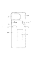
図1は、本発明の実施の形態に係る体液測定装置1(ここでは血糖値測定装置)の外観図である。
【0010】
本実施の形態に係る体液測定装置1は、蓋部材2bの開口部に挿入された被検者の指を穿刺して微量の体液(血液)を採取し体液の成分を測定するための体液測定装置である。この体液測定装置1のケース2は、ケース本体2aと、ケース本体2aに一端部が回動可能に取り付けられた蓋部材2bを有する。この蓋部材2bは、指先を挿入可能な開口部8(図3参照)と、開口部8側面に装着される保護カバー4を備えている。なお、蓋部材2bはなくてもよく、更に、蓋部材2bとしては、指先を挿入可能な開口部などを備えず、後述するチップ穿刺針組立体22(図3)の装着部7(図3)を単に被包可能に、ケース本体2aに一端部が回動可能に取り付けられたものであってもよい。さらに、蓋部材2bとしては、装着部に後述するチップ穿刺針組立体22(図4)が装着された状態では、蓋部材を完全に閉じることができないようになっていてもよい。
【0011】
3は穿刺開始スイッチで、このスイッチ3を押下することにより、後述する穿刺針を備える穿刺部材が開口部8内に突出し、そこに挿入されている被検者の指を穿刺する。6はリリースレバーで、露出する突起6a(図3)を備えており、このリリースレバー6を図1の上方向に移動させると突起6aにより押されて、チップ穿刺針組立体22(後述する)を装着部より離脱することができる。5は表示器で、測定した結果である血糖値や、操作者へのメッセージなどを表示する。
【0012】
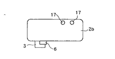
図2は、図1に示した体液測定装置1より保護カバー4を取り外した状態を示す側面図である。
【0013】
図2において、17は未使用のチップ穿刺針組立体22(図3)の残数確認用の小窓である。
【0014】
図3及び図4は、本実施の形態に係る体液測定装置1へのチップ穿刺組立体22の装着過程を説明する図である。
【0015】
このチップ穿刺針組立体22は、体液測定装置1の組立体装着部7に着脱可能に装着される。尚、このチップ穿刺針組立体22は、検査毎に交換される。
【0016】
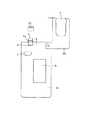
図5は、開口部8に被検者の指23が挿入されて、その被検者の体液(血液)を採取する状態を説明する図である。
【0017】
ここでは、チップ穿刺針組立体22先端の吸引口26を指23の穿刺部位に押し当て穿刺開始スイッチ3を押下することにより、穿刺針ホルダ20(図6)が加速前進して指23の皮膚への穿刺が行われる。
【0018】
図6は、本実施の形態に係る体液測定装置1にチップ穿刺針組立体22を装着した状態を示す断面図で、前述の図面と共通する部分は同じ番号で示し、その説明を省略する。
【0019】
図において、16は穿刺部材で、開口部8内に指先穿刺のために突出可能な穿刺針を備えている。25は検出チップで、体液中の特定成分と反応する試薬を含んでいる。バネ18は穿刺部材16を付勢して指先を穿刺させる。
【0020】
チップ穿刺針組立体22は、穿刺部材(ランセット)16と、この穿刺部材16を移動可能に収納する筒状部材と、筒状部材の先端部が固定された組立体本体部材を備える。この組立体22は、穿刺部材16の穿刺針の刃先の上方に位置し、指先に密着可能な環状開口部26と検出チップ25を備え、さらに、一端開口部が環状開口部26内に突出し他端がチップ25付近まで延びる体液誘導路を備えている。このため、穿刺部材16により穿刺されることにより生じた出血による血液は、この誘導路を通って検出チップ25に送られる。
【0021】
この誘導路は、その断面形状および長さは、測定に必要とする体液量により異なるが、体液の残存量を少なくなるように設計するのが望ましい。具体的には、断面形状としては管状、V字溝、長方形溝でも構わないが、体液の残存量を少なくできるため薄型の長方形が好ましい。また厚みは0.05〜0.5mm程度、幅は0.5〜3mm程度が好ましい。長さは、5mm〜15mm程度が適当である。
【0022】
チップ穿刺針組立体22の環状開口部(吸引口)26は、例えば指先、上腕、腹部、大腿部、耳たぶのような生体表面に接する部位である。この吸引口26は性別、年齢等の個人差や穿刺部位に拘わらず、良好に吸引採血が行えるように、その開口径(開口面積)が調整されている。具体的には、吸引口26の開口径は4〜10mmが好ましく、特に、穿刺部位が指や耳たぶの場合は4〜6mmがより好ましい。チップ穿刺針組立体22の吸引口26部の外周縁は、生体表面(皮膚)に押し当てたときに穿刺部周辺を刺激し穿刺時の痛みを和らげる効果を発揮するのに適した形状となっている。また、穿刺用具11内が減圧状態であるときに、チップ穿刺針組立体22と生体表面との間から空気が穿刺器具11へ流入することを阻止するのに適した形状となっている。
【0023】
穿刺用具11の一時的な突出を行うための穿刺針駆動機構は、筒状ハウジング27と、このハウジング27内部を摺動するプランジャ28と、このプランジャ28の後端に固定されたシャフト21と、このシャフト21の後端側を被包するようにハウジング27の後端部に取り付けられた調整カバー30と、バネ(弾性部材)18と、ハウジング27の側面開口部27aを覆う開口部カバー9と、穿刺開始スイッチ部材3を備える。プランジャ28は、側面にハウジング27の側面開口部27a内に侵入する係止用爪部19と、先端にチップ穿刺針組立体22の筒状部材内に侵入可能で、かつ先端に穿刺部材16の穿刺針ハブを保持可能な筒状の穿刺針ホルダ20を備えている。バネ18は、一端(先端)がプランジャ28の後端(シャフト21との接続部)に固定され、シャフト21の先端部分を被包し、後端はハウジング27の中央部に形成された内側に突出する弾性部材固定部29に固定されている。このため、図6に示すような、プランジャ28の係止用爪部19がハウジング27の開口部と係合する状態では、バネ18は、プランジャ28の後端とハウジング27の弾性部材固定部29間により圧縮された状態となっている。また、シャフト21には、後端部にリブ21aが、また調整カバー30は、その中間部に上記リブ21aと当接可能に設けられたリブ30aを備えている。この調整カバー30の位置を調整することにより穿刺針の突出量が調整される。12bは、吸引ポンプ12(図7)と穿刺針駆動機構の筒状ハウジング27とを接続するチューブである。104は発光素子で、採取された血液と反応する試薬を含む検出チップ25を照射している。105は受光素子で、検出チップ25から反射される反射光を受光して、その反射光強度(呈色の度合)を検出している。
【0024】
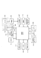
図7は、本実施の形態に係る体液測定装置1の構成を示すブロック図で、前述の図面と共通する部分は同じ番号で示し、その説明を省略する。
【0025】
図において、100は制御部で、例えばマイクロコンピュータ等のCPU、CPUにより実行される、装置全体の動作を制御する制御プログラムや各種データを記憶しているROM、CPUによる制御時にワークエリアとして使用され、測定データや各種データを一時的に保存するRAM等を備えている。101は素子駆動部で、制御部100よりの指示信号を入力して発光素子104をパルス駆動している。
【0026】
また発光素子104と受光素子105は、実際の体液検査のためだけでなく、体液接触前後の検出チップ25の状態を検出するための検出機構としても使用される。受光素子105から出力される受光光量に応じたアナログ信号は、増幅部106により増幅された後、AD変換器107にてデジタル信号に変換されて制御部100に入力される。こうして制御部100は、デジタル信号として入力される受光素子105の出力変化により、検出チップ25に体液が吸引されたことを判断することができる。
【0027】
また本実施の形態に係る体液測定装置1は、チップ穿刺針組立体の装着を監視するための監視センサ103、蓋開閉センサ115を備え、体液測定装置1の休止状態から測定可能な状態までを検知可能となっている。具体的には、蓋開閉センサ115により蓋部材2bの開放が検知され、かつ、チップ穿刺針組立体装着監視センサ103によりチップ穿刺針組立体22の装着が確認されることにより、測定可能な状態になったことを検知する。この蓋開閉センサ115としては、機械式が好ましいが電気式、光式でもよい。また体液測定装置1は、検出チップ25での反応を光学的に測定する際、ケース2の蓋部材2bおよびこの蓋部材2bに設けられた保護カバー4により、検出チップ25への外光の侵入を阻止し、測定精度を向上させている。114は電源部で、例えば電池等を備えており、装置全体への電力供給を行っている。
【0028】
穿刺開始検出センサ110は、チップ穿刺針組立体22による穿刺が開始したことを検出するセンサであり、穿刺開始スイッチ3と連動するか、もしくは穿刺針駆動機構の穿刺駆動する部位に設けられる。この穿刺開始検出センサ110は、磁気式センサ、機械式センサ、光式センサいずれでもよく、また圧力センサ108は、吸引ポンプ12と穿刺針駆動機構内部とを連通するチューブ内に設けられており、例えば、半導体型圧力センサが好適に使用される。この圧力センサ108を設けることにより、吸引ポンプ12の作動時の体液吸引が正しく行われているか監視することができる。具体的には、指23とチップ穿刺針組立体22の開口部との接触が正しく行われずにリークが起きていることが検知でき、これを制御部100が検知して表示器5による警告表示、もしくは音声出力部113により音声等によるエラーメッセージを出力する。
【0029】
表示器5は、制御部100からの信号に基づいて体液検査結果、或いはオペレータへのメッセージなどを表示するためのものであり、液晶ディスプレイが好適に使用される。また音声出力部113は、制御部100からの信号に基づいてブザー音、又は音声を出力するものである。外部出力部111は、メモリ(記憶部)112に記憶された体液測定結果(例えば血糖値等のデータ)をパソコン(PC)のような外部装置へ出力するためのものである。この場合、外部出力部111は、例えばRS232Cのような通信回路を内蔵している。また赤外線通信を行う場合には、外部出力部111は、赤外線発光素子、及びその駆動回路を備えている。メモリ112は、体液検出結果(例えば血糖値等のデータ)を測定時間とともに記憶するためのものである。
【0030】
次に本実施の形態に係る体液測定装置1を用いた体液の採取、測定を行う際の各部の操作について説明する。
【0031】
体液測定装置1のケース2の蓋部材2bが開かれると、その蓋部材2bが開かれたことが蓋開閉センサ115により検知され、その結果が制御部100に伝えられる。これにより制御部100は、操作者(又は被検者)にチップ穿刺針組立体22の取り付け指示を表示器5に表示する。これにより操作者が、チップ穿刺針組立体22をチップ穿刺針組立体装着部7にセットし、プランジャ28の係止用爪部19がハウジング27の開口部と係合する状態まで押し込む。これにより図6に示す状態となり、バネ18は圧縮状態で保持される。
【0032】
この状態において、発光素子104、受光素子105は作動しており、この受光素子105により検出された信号はA/D変換器107で変換されて制御部100に入力される。これにより制御部100は、チップ穿刺針組立体22の試薬反応部の白色を検知でき、これによりチップ穿刺針組立体22が取り付けられたことを判定できる。これと同時に、チップ穿刺針組立体装着監視センサ103により、穿刺具が穿刺可能な位置まで押し込まれているか検知し、その検知結果が制御部100に入力される。こうしてチップ穿刺針組立体22が穿刺可能な位置まで押し込まれたことが確認されると、表示器5に穿刺開始可能状態となった旨を表示する。
【0033】
次に図5に示すように、チップ穿刺針組立体22先端の吸引口26を指等の穿刺部位に押し当て穿刺開始スイッチ3を図6の矢印F方向に押すと、この開始スイッチ3の係合解除用チップ部3bにより、ハウジング27の係合用爪侵入用開口部部分(開口部に侵入した爪部の先端部)を開口部カバー9を介して押圧し、プランジャ28の係止用爪部19のハウジング27の開口部との係合を解除する。これによりバネ18が圧縮状態から解放されランセット16と穿刺針ホルダ20は加速前進し、ランセット16の刃先による皮膚への穿刺が行われる。この穿刺後、ランセット16と穿刺針ホルダ20は、バネ18の減衰運動によりケース2内に収納される。
【0034】
また、穿刺開始検出センサ110により穿刺開始が検知されると、制御部100は吸引ポンプ12を動作させ、穿刺針による指先の穿刺部位を含む周辺部位を吸引するために穿刺針駆動機構内部を吸引する。なお、この穿刺開始検出センサ110を設けることなく、穿刺開始スイッチ3により、直接吸引手段が作動するようにしてもよい。また、吸引ポンプ12の作動開始のタイミングは、穿刺が行われたのと同時でも、或いは若干遅れてもよい。尚、この吸引ポンプ12による圧力は陰圧で、200mmHg〜600mmHgが好ましく、特に400mmHg以上が好ましい。これにより、短時間で必要量の血液を穿刺部位より流出させることができる。こうして皮膚上に出血した体液は、チップ25の内壁の溝を伝って試験紙に染み込む。この状態で測定が開始し、その結果が表示器5に表示される。この測定終了後、チップ穿刺針組立体リリースレバー6によりチップ穿刺針組立体22を装着部7から外し、測定が終了する。
【0035】
次に本発明の実施の形態に係る体液測定装置1の制御部100による制御動作を説明する。前述したように、本実施の形態に係る体液測定装置1は、例えば血糖測定装置であり、被検者の指から採取した血液をチップ25内の試薬層と反応させ、その反応に基づく試薬層の呈色の度合を基に、その血液中に含まれる血糖濃度を測定するするものである。よって、ここでは発光素子104からの光をチップ25に照射し、その反射光強度を受光素子105により検出することにより、その呈色の度合を検出している。
【0036】
しかしながら、この発光素子として使用するLEDは、その熱特性等により、図8(A)に示すように、点灯時からの経過時間に応じて、その発光する光量が減少することが知られている。このような特性は図8(B)のように、パルス信号で駆動する場合にも、最初のパルスと後続のパルスの場合とでは、そのれら駆動パルスに対応する発光特性が変動していると考えられる。従って、本実施の形態では、パルス駆動の開始時から所定時間の経過を待った後の複数のパルス信号を用い、それら複数のパルス信号による駆動による発光の下で検出される反射光強度に基づいて血糖値を測定することを特徴としている。
【0037】
図9は、このようなLEDを用いて計測した際のデータサンプリングを説明する図である。ここではLEDをパルス信号により駆動する際、そのパルス信号の周期を12m秒(6m秒オン、6m秒オフ)、毎秒当り点灯20回(1バースト:240msで、残りの760msはオフのまま)とした。これによる20(回/秒)の応答出力の内、1点から20点までの毎秒当りの平均値を求めるために用いるデータ点数を変化させた際の、20(20秒間)の演算結果のバラツキ(C.V.値)を示している。図中、900は、各1バーストにおける20パルスの応答の内、平均値を求めるのに用いるデータ点数を前からn点(n=16)とした場合の例を示している。また901は、各1バーストにおける20パルスの応答の内、平均値を求めるのに用いるデータ点数を後からn点(n=16)とした場合の例を示している。尚、このLEDは中心波長が600nmで、点灯電流15mAのものを使用し、その発光量を受光素子(フォントセンサ)により測定した。
【0038】
この図9からも明らかなように、各バーストで印加されるパルス(20パルス)の全てに対応した出力に基づいて各バーストで検出した発光量の平均値を求めた場合に比べて、毎秒当りのバースト(20パルス)のパルス応答のうちで、後の16のデータだけを用いて毎秒当りの平均値を求めた場合の方が、1秒当りの計算値の繰り返し再現が良くなることが分かる。
【0039】
従って、本実施の形態に係る体液測定装置では、この図9の901で示す特性を利用して、駆動開始後、例えば5秒間は反射光強度を検出せず、この5秒経過後、1秒間に印加するパルス信号(例えば20パルス)の内、最後のパルス信号を含む連続するパルス信号(例えば16パルス)による駆動時の反射光強度を求め、これら反射光強度の平均値を基に、その体液の特性値、例えば血液の血糖値を検出するようにしている。
【0040】
図10は、本実施の形態に係る体液測定装置における測定処理を示すフローチャートで、この処理は制御部100のCPUにより実行される。
【0041】
この処理は、例えば測定開始スイッチ(不図示)が押下されるか、或いはチップ穿刺針組立体22が装置に装着され、穿刺開始スイッチ3により被検者の指が穿刺されて体液(血液)が採取されて試験層の呈色が開始されること等により測定開始になると開始され、まずステップS1で、発光素子104を、例えば1秒間に20回の割り合いでパルス駆動し、ステップS2で、これらパルス信号の印加の開始後、所定時間(例えば5秒)が経過したかをみる。5秒が経過するまではステップS1,S2の処理を実行し、所定時間が経過するとステップS3に進み、発光素子104を、例えば1秒間に20回の割り合いでパルス駆動しながら、各パルス駆動のタイミングに同期して受光素子105により検出される反射光強度を入力し、それらをメモリ112に記憶する。
【0042】
次にステップS4に進み、そのメモリ112に記憶した毎秒20個の反射光強度データの内、最後から16個のデータを読み出し、それらの平均値を求める。そしてステップS5に進み、その求めた反射光強度の平均値を用いて、演算式により血糖値を求める。こうして求めた血糖値をメモリ112に、その測定日時とともに記憶する。また、その測定結果を表示器5に表示する。
【0043】
尚、上述した1秒間の測定結果の内、どの測定結果を平均値の算出に用いるかについては、上述した方法以外に、例えば以下のような方法が考えられる。
・熱影響によるLEDの光量減少を、各パルス駆動信号に対応する発光量をモニタして記憶しておき、その変化率が、例えば0.5〜5%程度になる区間を、安定区間として判定する。
【0044】
この平均値を求める安定区間の判定に際しては、最初のパルスを基準にして光量の変化率をみるか、最後尾のパルス信号を基準に、前のパルス信号に対応する光量との変化率をみることにより求める。例えば、カラースケール評価の結果より変化率が1%以内、好ましくは0.5%以内とすれば、血糖換算値への影響を少なくして安定区間かどうかの判定を行うことができる。
【0045】
尚、上記の1秒毎のパルス駆動回数や、平均値を求めるのに採用した測定回数、区間を判定するための変化率等は、あくまでも一例であり、本発明はこれら数値に限定されるものでないことはもちろんである。
【0046】
以上説明したように本実施の形態によれば、測定時間の延長をできるだけ少なくしながら、発光素子の発光光量の変動に伴う影響を少なくして、被検者の体液(血液)の特性を測定することができる。
【0047】
【発明の効果】
以上説明したように本発明によれば、測定時間の増大を抑えながら、発光特性が安定した状態で測定できるという効果がある。
【図面の簡単な説明】
【図1】本発明の実施の形態に係る体液測定装置の上面図である。
【図2】本発明の実施の形態に係る体液測定装置より保護カバーを取り外した状態を示す側面図である。
【図3】本実施の形態に係る体液測定装置へのチップ穿刺組立体の装着過程を説明する図である。
【図4】本実施の形態に係る体液測定装置へのチップ穿刺組立体の装着過程を説明する図である。
【図5】本実施の形態に係る体液測定装置の開口部に被検者の指が挿入されて、その被検者の体液(血液)を採取する状態を説明する図である。
【図6】本実施の形態に係る体液測定装置にチップ穿刺針組立体を装着した状態を示す断面図である。
【図7】本実施の形態に係る体液測定装置の構成を示すブロック図である。
【図8】発光素子の光量変化例を説明する図である。
【図9】発光素子を駆動する際、サンプリングの仕方に応じたデータの平均点数と発光光量との実験例を説明するグラフ図である。
【図10】本発明の実施の形態に係る体液測定装置における測定処理を示すフローチャートである。[0001]
BACKGROUND OF THE INVENTION
The present invention relates to a measuring device for body fluid, such as blood, and in particular, reacts a body fluid collected from a subject with a reagent and detects the color of the reagent based on reflected light, thereby detecting the characteristic value of the body fluid. The present invention relates to a body fluid measuring device for obtaining the above.
[0002]
[Prior art]
In recent years, with the increase in the number of diabetic patients, self blood glucose measurement in which patients themselves monitor fluctuations in daily blood sugar levels has been recommended. In this self blood glucose level measurement, a test paper that is colored according to the amount of glucose in the blood is attached to the device, blood is supplied to the test paper, and the degree of coloration of the test paper is optically measured (measured). A blood glucose measuring device that quantifies the blood glucose level is used.
[0003]
In such a blood glucose measurement device, for example, a light emitting element such as an LED is driven to irradiate a test paper that is colored by reacting with blood, and the reflected light intensity from the test paper is measured by a light such as a photodetector. The detection color is detected by a detector, the reaction color of the test paper is obtained, and the blood sugar level of the blood attached thereto is obtained.
[0004]
[Problems to be solved by the invention]
In such a device, in order to reduce power consumption, the light emitting element is normally turned off, the light emitting element is driven to emit light immediately before starting the measurement, and the light emitting element is turned off when the measurement process is completed. Like to do. As such a light emitting element, an LED is generally used from the viewpoint of small size, cost and power consumption.
[0005]
In such an LED, it is known that the light emission characteristics change immediately after the start of energization and after a short time has elapsed since the start of energization due to the influence of heat due to the light emission. Therefore, even if the blood glucose level is the same, the result measured with light immediately after the start of driving a light emitting element such as an LED may differ from the result measured after a predetermined time has elapsed since the start of driving. is expected. Further, if the measurement is always performed with a time interval until the light emission characteristics are completely stabilized, the time required for the measurement becomes long, which makes it difficult for the operator to use.
[0006]
The present invention has been made in view of the above-described conventional example, and an object of the present invention is to provide a body fluid measuring device that performs measurement in a state where light emission characteristics are stable while suppressing an increase in measurement time.
[0007]
[Means for Solving the Problems]
In order to achieve the above object, the body fluid measuring device of the present invention has the following configuration. That is,
A test member including a reagent layer that reacts with a bodily fluid obtained by puncturing the skin of a subject and colors;
Irradiating means for irradiating the test member with light;
Detection means for detecting reflected light intensity irradiated by the irradiation means and reflected by the test member;
Driving means for drive the said irradiating means a burst comprising a pulse signal of consecutive Tokoro constant by intermittently output,
After the elapse of a predetermined time from the start of driving by the pulse signal , the predetermined number of the reflected light intensities detected by the detecting means in synchronization with the driving by the burst by the driving means in each of the bursts. An average value calculating means for calculating an average value of reflected light intensity corresponding to a plurality of pulse signals less than the predetermined number including the last pulse signal among the continuous pulse signals;
Calculating means for calculating a characteristic value of the body fluid of the subject based on the average value calculated by the average value calculating means.
[0008]
DETAILED DESCRIPTION OF THE INVENTION
Preferred embodiments of the present invention will be described below in detail with reference to the accompanying drawings.
[0009]
FIG. 1 is an external view of a body fluid measuring device 1 (here, a blood glucose level measuring device) according to an embodiment of the present invention.
[0010]
The bodily fluid measurement device 1 according to the present embodiment is a bodily fluid measurement for puncturing the subject's finger inserted into the opening of the
[0011]
3 is a puncture start switch. When the
[0012]
FIG. 2 is a side view showing a state in which the protective cover 4 is removed from the body fluid measuring device 1 shown in FIG.
[0013]
In FIG. 2, 17 is a small window for checking the remaining number of the unused tip puncture needle assembly 22 (FIG. 3).
[0014]
3 and 4 are diagrams for explaining the mounting process of the
[0015]
The tip
[0016]
FIG. 5 is a diagram for explaining a state in which the subject's
[0017]
Here, the
[0018]
FIG. 6 is a cross-sectional view showing a state in which the tip
[0019]
In the figure,
[0020]
The chip
[0021]
Although the cross-sectional shape and length of this guide path vary depending on the amount of body fluid required for measurement, it is desirable to design the guide path so as to reduce the remaining amount of body fluid. Specifically, the cross-sectional shape may be a tubular shape, a V-shaped groove, or a rectangular groove, but a thin rectangular shape is preferable because the remaining amount of body fluid can be reduced. The thickness is preferably about 0.05 to 0.5 mm, and the width is preferably about 0.5 to 3 mm. A length of about 5 mm to 15 mm is appropriate.
[0022]
The annular opening (suction port) 26 of the tip
[0023]
The puncture needle drive mechanism for temporarily projecting the puncture device 11 includes a
[0024]
FIG. 7 is a block diagram showing the configuration of the bodily fluid measurement device 1 according to the present embodiment. The same parts as those in the above-mentioned drawings are denoted by the same reference numerals, and the description thereof is omitted.
[0025]
In the figure,
[0026]
The light emitting element 104 and the
[0027]
The body fluid measuring device 1 according to the present embodiment includes a
[0028]
The puncture
[0029]
The
[0030]
Next, the operation of each part when collecting and measuring body fluid using the body fluid measuring device 1 according to the present embodiment will be described.
[0031]
When the
[0032]
In this state, the light emitting element 104 and the
[0033]
Next, as shown in FIG. 5, when the
[0034]
When the puncture
[0035]
Next, the control operation by the
[0036]
However, it is known that the amount of light emitted from the LED used as the light-emitting element decreases according to the elapsed time from lighting, as shown in FIG. . As shown in FIG. 8B, such characteristics vary even in the case of driving with a pulse signal, even in the case of the first pulse and the subsequent pulse, the light emission characteristics corresponding to these driving pulses fluctuate. it is conceivable that. Therefore, in the present embodiment, a plurality of pulse signals after waiting for the elapse of a predetermined time from the start of pulse driving are used, and based on the reflected light intensity detected under light emission by driving with the plurality of pulse signals. It is characterized by measuring blood glucose level.
[0037]
FIG. 9 is a diagram for explaining data sampling when measurement is performed using such an LED. Here, when the LED is driven by a pulse signal, the period of the pulse signal is 12 msec (6 msec on, 6 msec off),
[0038]
As can be seen from FIG. 9, compared to the case where the average value of the amount of light emission detected in each burst is obtained based on the output corresponding to all the pulses (20 pulses) applied in each burst, Of the pulse responses of the burst (20 pulses), it can be seen that the repeated reproduction of the calculated value per second is better when the average value per second is obtained using only the subsequent 16 data. .
[0039]
Therefore, in the body fluid measuring device according to the present embodiment, the characteristic indicated by
[0040]
FIG. 10 is a flowchart showing a measurement process in the body fluid measurement device according to the present embodiment. This process is executed by the CPU of the
[0041]
For example, the measurement start switch (not shown) is pressed, or the tip
[0042]
Next, the process proceeds to step S4, and the last 16 pieces of data are read out from the 20 pieces of reflected light intensity data stored in the
[0043]
In addition to the method described above, for example, the following method can be considered as to which measurement result is used for calculating the average value among the measurement results for one second described above.
-The LED light quantity decrease due to thermal effects is monitored and stored by monitoring the light emission amount corresponding to each pulse drive signal, and the section where the rate of change is, for example, about 0.5 to 5% is determined as the stable section. To do.
[0044]
When determining the stable interval for obtaining the average value, the change rate of the light amount is observed with reference to the first pulse, or the change rate with the light amount corresponding to the previous pulse signal is determined with reference to the last pulse signal. By seeking. For example, if the rate of change is within 1%, preferably within 0.5%, based on the results of color scale evaluation, it is possible to determine whether or not it is a stable interval with less influence on the blood glucose conversion value.
[0045]
The number of pulse drives per second, the number of measurements employed to determine the average value, the rate of change for determining the interval, etc. are merely examples, and the present invention is limited to these numerical values. Of course not.
[0046]
As described above, according to the present embodiment, the characteristics of the body fluid (blood) of the subject are measured while reducing the extension of the measurement time as much as possible and reducing the influence of fluctuations in the amount of light emitted from the light emitting element. can do.
[0047]
【The invention's effect】
As described above, according to the present invention, there is an effect that measurement can be performed in a state in which light emission characteristics are stable while suppressing an increase in measurement time.
[Brief description of the drawings]
FIG. 1 is a top view of a body fluid measuring device according to an embodiment of the present invention.
FIG. 2 is a side view showing a state in which a protective cover is removed from the body fluid measuring device according to the embodiment of the present invention.
FIG. 3 is a diagram for explaining a mounting process of the chip puncture assembly to the body fluid measuring device according to the present embodiment.
FIG. 4 is a view for explaining a mounting process of the chip puncture assembly to the body fluid measuring device according to the present embodiment.
FIG. 5 is a diagram illustrating a state in which a subject's finger is inserted into the opening of the body fluid measuring device according to the present embodiment and the body fluid (blood) of the subject is collected.
FIG. 6 is a cross-sectional view showing a state in which the tip puncture needle assembly is mounted on the body fluid measuring device according to the present embodiment.
FIG. 7 is a block diagram showing a configuration of a body fluid measuring device according to the present embodiment.
FIG. 8 is a diagram illustrating an example of a change in light amount of a light emitting element.
FIG. 9 is a graph illustrating an experimental example of the average number of data and the amount of emitted light according to the sampling method when driving the light emitting element.
FIG. 10 is a flowchart showing a measurement process in the body fluid measurement device according to the embodiment of the present invention.
Claims (2)
前記試験部材に光を照射する照射手段と、
前記照射手段により照射され前記試験部材により反射された反射光強度を検出する検出手段と、
所定数の連続するパルス信号からなるバーストを間歇的に出力して前記照射手段を駆動する駆動手段と、
前記パルス信号による駆動の開始時から所定時間の経過後、前記駆動手段による前記バーストによる駆動に同期して前記検出手段により検出される反射光強度の内、各々の前記バースト内の前記所定数の連続するパルス信号のうち、最終のパルス信号を含む連続する前記所定数未満の複数のパルス信号に対応する反射光強度の平均値を算出する平均値算出手段と、
前記平均値算出手段により算出された平均値を基に前記被検者の体液の特性値を演算して求める演算手段と、
を有することを特徴とする体液測定装置。A test member including a reagent layer that reacts with a bodily fluid obtained by puncturing the skin of a subject and colors;
Irradiating means for irradiating the test member with light;
Detection means for detecting reflected light intensity irradiated by the irradiation means and reflected by the test member;
Driving means for drive the said irradiating means a burst comprising a pulse signal of consecutive Tokoro constant by intermittently output,
After the elapse of a predetermined time from the start of driving by the pulse signal , the predetermined number of the reflected light intensities detected by the detecting means in synchronization with the driving by the burst by the driving means in each of the bursts. An average value calculating means for calculating an average value of reflected light intensity corresponding to a plurality of pulse signals less than the predetermined number including the last pulse signal among the continuous pulse signals;
Calculation means for calculating the characteristic value of the subject's body fluid based on the average value calculated by the average value calculation means;
A bodily fluid measuring device comprising:
Priority Applications (1)
| Application Number | Priority Date | Filing Date | Title |
|---|---|---|---|
| JP2000369069A JP4409753B2 (en) | 2000-12-04 | 2000-12-04 | Body fluid measuring device |
Applications Claiming Priority (1)
| Application Number | Priority Date | Filing Date | Title |
|---|---|---|---|
| JP2000369069A JP4409753B2 (en) | 2000-12-04 | 2000-12-04 | Body fluid measuring device |
Publications (2)
| Publication Number | Publication Date |
|---|---|
| JP2002168862A JP2002168862A (en) | 2002-06-14 |
| JP4409753B2 true JP4409753B2 (en) | 2010-02-03 |
Family
ID=18839167
Family Applications (1)
| Application Number | Title | Priority Date | Filing Date |
|---|---|---|---|
| JP2000369069A Expired - Fee Related JP4409753B2 (en) | 2000-12-04 | 2000-12-04 | Body fluid measuring device |
Country Status (1)
| Country | Link |
|---|---|
| JP (1) | JP4409753B2 (en) |
Families Citing this family (19)
| Publication number | Priority date | Publication date | Assignee | Title |
|---|---|---|---|---|
| US7004928B2 (en) | 2002-02-08 | 2006-02-28 | Rosedale Medical, Inc. | Autonomous, ambulatory analyte monitor or drug delivery device |
| JP4762341B2 (en) * | 2003-10-29 | 2011-08-31 | アークレイ株式会社 | Puncture device |
| JP4484669B2 (en) * | 2003-10-29 | 2010-06-16 | アークレイ株式会社 | Puncture device |
| US20060281187A1 (en) | 2005-06-13 | 2006-12-14 | Rosedale Medical, Inc. | Analyte detection devices and methods with hematocrit/volume correction and feedback control |
| WO2007041244A2 (en) | 2005-09-30 | 2007-04-12 | Intuity Medical, Inc. | Multi-site body fluid sampling and analysis cartridge |
| JP2007244736A (en) * | 2006-03-17 | 2007-09-27 | Toshiba Corp | Living body component measuring device and method |
| WO2007116675A1 (en) | 2006-03-28 | 2007-10-18 | Terumo Kabushiki Kaisha | Body fluid components measuring device |
| JP2011522594A (en) | 2008-06-06 | 2011-08-04 | インテュイティ メディカル インコーポレイテッド | Medical diagnostic apparatus and method |
| CA2726067C (en) | 2008-06-06 | 2020-10-20 | Intuity Medical, Inc. | Detection meter and mode of operation |
| JP5336314B2 (en) * | 2009-09-17 | 2013-11-06 | テルモ株式会社 | Blood glucose meter |
| US8919605B2 (en) | 2009-11-30 | 2014-12-30 | Intuity Medical, Inc. | Calibration material delivery devices and methods |
| EP2584964B1 (en) | 2010-06-25 | 2021-08-04 | Intuity Medical, Inc. | Analyte monitoring devices |
| JP5756318B2 (en) * | 2011-03-31 | 2015-07-29 | テルモ株式会社 | Blood glucose level measuring device |
| WO2013002318A1 (en) * | 2011-06-29 | 2013-01-03 | テルモ株式会社 | Component measuring device and medical instrument |
| CA2912283A1 (en) | 2013-06-21 | 2014-12-21 | Intuity Medical, Inc. | Analyte monitoring system with audible feedback |
| JP2017176263A (en) * | 2016-03-28 | 2017-10-05 | 富士ゼロックス株式会社 | Apparatus and program for measuring biological information |
| JP2017176264A (en) * | 2016-03-28 | 2017-10-05 | 富士ゼロックス株式会社 | Apparatus and program for measuring biological information |
| CN109247945A (en) | 2017-07-12 | 2019-01-22 | 松下知识产权经营株式会社 | measuring device |
| EP4353150A1 (en) | 2022-08-09 | 2024-04-17 | Fujita Medical Instruments Co., Ltd. | Biometric information detection device and biometric information detection method |
Family Cites Families (2)
| Publication number | Priority date | Publication date | Assignee | Title |
|---|---|---|---|---|
| US4810090A (en) * | 1987-08-24 | 1989-03-07 | Cobe Laboratories, Inc. | Method and apparatus for monitoring blood components |
| JP3618210B2 (en) * | 1997-03-19 | 2005-02-09 | テルモ株式会社 | Component measuring device |
-
2000
- 2000-12-04 JP JP2000369069A patent/JP4409753B2/en not_active Expired - Fee Related
Also Published As
| Publication number | Publication date |
|---|---|
| JP2002168862A (en) | 2002-06-14 |
Similar Documents
| Publication | Publication Date | Title |
|---|---|---|
| JP4409753B2 (en) | Body fluid measuring device | |
| US5820557A (en) | Blood glucose measurement apparatus | |
| US8858467B2 (en) | Lancing and analysis device | |
| US6197257B1 (en) | Micro sensor device | |
| JP4286226B2 (en) | Body fluid testing device | |
| US8986223B2 (en) | Test media cassette for bodily fluid testing device | |
| CA2623589C (en) | Catalysts for body fluid sample extraction | |
| US6157442A (en) | Micro optical fiber sensor device | |
| EP2479575B1 (en) | Blood glucose meter | |
| US20080200838A1 (en) | Wearable, programmable automated blood testing system | |
| US20030018282A1 (en) | System for withdrawing small amounts of body fluid | |
| JP2005521452A (en) | Integrated sample tester | |
| KR20030030939A (en) | Devices for physiological fluid sampling and methods of using the same | |
| JPWO2008096552A1 (en) | Blood test equipment | |
| JP2000152923A (en) | Component measuring device | |
| US9289162B2 (en) | Control device for a medical test system | |
| JP3742741B2 (en) | Body fluid testing device | |
| JP4493172B2 (en) | Component measuring device | |
| JPWO2006109453A1 (en) | Puncture device and puncture tip | |
| JP4493181B2 (en) | Component measuring device | |
| JPWO2004110275A1 (en) | Biological information measuring device and biological information measuring method | |
| JP4233496B2 (en) | Body fluid testing device | |
| JP2007181602A (en) | Portable blood sugar level measuring instrument | |
| JP2002168861A (en) | Apparatus for measuring component | |
| JP5675655B2 (en) | Portable analysis device |
Legal Events
| Date | Code | Title | Description |
|---|---|---|---|
| A621 | Written request for application examination |
Free format text: JAPANESE INTERMEDIATE CODE: A621 Effective date: 20070416 |
|
| A977 | Report on retrieval |
Free format text: JAPANESE INTERMEDIATE CODE: A971007 Effective date: 20090423 |
|
| A131 | Notification of reasons for refusal |
Free format text: JAPANESE INTERMEDIATE CODE: A131 Effective date: 20090507 |
|
| A521 | Written amendment |
Free format text: JAPANESE INTERMEDIATE CODE: A523 Effective date: 20090706 |
|
| TRDD | Decision of grant or rejection written | ||
| A01 | Written decision to grant a patent or to grant a registration (utility model) |
Free format text: JAPANESE INTERMEDIATE CODE: A01 Effective date: 20091019 |
|
| A01 | Written decision to grant a patent or to grant a registration (utility model) |
Free format text: JAPANESE INTERMEDIATE CODE: A01 |
|
| A61 | First payment of annual fees (during grant procedure) |
Free format text: JAPANESE INTERMEDIATE CODE: A61 Effective date: 20091112 |
|
| R150 | Certificate of patent or registration of utility model |
Free format text: JAPANESE INTERMEDIATE CODE: R150 Ref document number: 4409753 Country of ref document: JP Free format text: JAPANESE INTERMEDIATE CODE: R150 |
|
| FPAY | Renewal fee payment (event date is renewal date of database) |
Free format text: PAYMENT UNTIL: 20121120 Year of fee payment: 3 |
|
| FPAY | Renewal fee payment (event date is renewal date of database) |
Free format text: PAYMENT UNTIL: 20121120 Year of fee payment: 3 |
|
| FPAY | Renewal fee payment (event date is renewal date of database) |
Free format text: PAYMENT UNTIL: 20131120 Year of fee payment: 4 |
|
| R250 | Receipt of annual fees |
Free format text: JAPANESE INTERMEDIATE CODE: R250 |
|
| LAPS | Cancellation because of no payment of annual fees |