JP4408202B2 - Game machine - Google Patents
Game machine Download PDFInfo
- Publication number
- JP4408202B2 JP4408202B2 JP2003122999A JP2003122999A JP4408202B2 JP 4408202 B2 JP4408202 B2 JP 4408202B2 JP 2003122999 A JP2003122999 A JP 2003122999A JP 2003122999 A JP2003122999 A JP 2003122999A JP 4408202 B2 JP4408202 B2 JP 4408202B2
- Authority
- JP
- Japan
- Prior art keywords
- display
- moving image
- image
- data
- variable display
- Prior art date
- Legal status (The legal status is an assumption and is not a legal conclusion. Google has not performed a legal analysis and makes no representation as to the accuracy of the status listed.)
- Expired - Fee Related
Links
Images


Description
【0001】
【発明の属する技術分野】
本発明は、パチンコ遊技機等の遊技機に係り、詳しくは、可変表示の実行条件が成立した後に可変表示の開始条件が成立したことに基づいて、各々が識別可能な複数種類の識別情報を可変表示する可変表示装置を備え、識別情報の表示結果が特定表示結果となったときに遊技者にとって有利な特定遊技状態とする遊技機に関する。
【0002】
【従来の技術】
パチンコ遊技機等の遊技機においては、液晶表示装置(以下LCD:Liquid Crystal Display)等の表示装置上に所定の識別情報(以下、表示図柄)を更新表示させることで可変表示を行い、その表示結果により所定の遊技価値を付与するか否かを決定する、いわゆる可変表示ゲームによって遊技興趣を高めたものが数多く提供されている。
【0003】
可変表示ゲームには、主に、前述した表示装置を画像表示装置として用いることにより行うもの(以下、特図ゲーム)がある。特図ゲームは、所定領域を通過する遊技球の検出に伴って表示図柄の更新表示を行い、表示図柄の更新表示が完全に停止した際の停止図柄態様が特定表示態様となっている場合を「大当り」とするゲームである。特図ゲームにおいて「大当り」となると、大入賞口またはアタッカと呼ばれる特別電動役物を開放状態とし、遊技者に対して遊技球の入賞が極めて容易となる状態を一定時間継続的に提供する。
【0004】
ここで、特図ゲームにおいて大当りとなり、特別電動役物が開放状態となることにより、遊技者に対して遊技球の入賞がきわめて容易となる状態となることを特定遊技状態という。特定遊技状態となるためには、通常、表示図柄の停止図柄態様が予め定められた特定表示態様となること(一般的には表示図柄が同一図柄で揃うこと)が条件となる。
【0005】
このように、遊技者にとって特図ゲームは、停止図柄態様が特定表示態様となって「大当り」となるか否かに最大の関心が払われることになる。このため、「大当り」となるか否かを判別することのできる停止図柄態様の確定までの間は、遊技興趣を高めるために様々な演出表示が行われることがある。
【0006】
このような演出表示として、表示装置に動画像を表示することが考えられる。動画像を表示する技術としては、圧縮画像データを所定の画像データ伸長アルゴリズムにより伸長させ動画像を表示するものが提案されている(例えば、特許文献1)。
【0007】
【特許文献1】
特開2002−312807号公報
【0008】
【発明が解決しようとする課題】
特許文献1に開示された技術によると、演出表示として圧縮画像データを使用した動画像の表示を行うことができるが、圧縮画像データの使用頻度が多いときには、データ圧縮された動画像データの伸長処理や再生処理などのための制御負担が大きくなってしまうという問題がある。
【0009】
また、動画像による演出表示を行う場合、複数種類の演出表示のいずれが行われたかに応じて表示図柄の停止図柄態様が特定表示態様となる確率を異ならせることで、遊技者の期待度を向上させることが考えられる。しかしながら、各々の演出表示に合わせて別々の動画像を表示すると、膨大なデータ量の動画像データが必要となる。従って、複数種類の演出表示を行うためには、データ圧縮されてはいるが、多大なデータ量の動画像データを必要とするので、動画像データの総データ量が増大することになってしまい、動画像データを格納する記憶領域の必要容量が増大してしまうという問題があった。また、多大なデータ量の動画像データを必要とするので、データ圧縮された動画像データの伸長処理や再生処理などのための制御負担が増大するという問題もある。
【0010】
本発明は、上記実状に鑑みてなされたものであり、データ圧縮された動画像データを用いた演出表示のための制御負担を軽減することができる遊技機を提供することを目的とする。
【0011】
【課題を解決するための手段】
上記目的を達成するため、本発明の遊技機は、可変表示の実行条件(例えば普通可変入賞球装置6への入賞)が成立した後に可変表示の開始条件(例えば可変表示装置4における前回の可変表示及び大当り遊技状態の終了)が成立したことに基づいて、各々が識別可能な複数種類の識別情報を可変表示する可変表示装置(例えば可変表示装置4)を備え、識別情報の表示結果が特定表示結果となったときに遊技者にとって有利な特定遊技状態(例えば大当り遊技状態)とする遊技機であって、動き補償予測符号化による圧縮データを含む動画像データを格納する圧縮データ格納手段(例えばCGROM116の動画像データ格納領域116b)と、前記圧縮データ格納手段に格納されている動画像データを伸長するデータ伸長手段(例えばGCL115のデータ伸長部160)と、前記データ伸長手段により伸長された動画像データに基づいて生成される画像を前記可変表示装置に順次表示させることによって動画再生を行うデータ再生手段(例えばGCL115のデータ再生部161)と、識別情報の可変表示を実行しているときに、前記データ再生手段が行う動画再生による動画像を用いた演出表示を前記可変表示装置に行わせる演出表示制御手段(例えばCPU112やGCL115など)と、所定の数値データを更新する数値データ更新手段(例えばCPU103がステップS23の処理を実行する部分など)と、可変表示の実行条件の成立に応じて前記数値データ更新手段が更新する数値データを抽出する数値データ抽出手段(例えばCPU103がステップS101の入賞処理を実行する部分など)と、前記数値データ抽出手段が抽出した数値データを、抽出順番を特定可能に記憶する保留記憶手段(例えば特図保留メモリ120)と、前記保留記憶手段に記憶された数値データが所定の判定値データ(例えば通常時大当り判定テーブル140、確変時大当り判定テーブル141にて「大当り」の表示結果と対応付けられているランダムR1の値を示すデータ)と合致するか否かに応じて表示結果として特定表示結果を表示するか否かを判定する事前判定手段(例えばCPU103がステップS303の大当り判定処理を実行する部分)と、前記事前判定手段により前記保留記憶手段に記憶された数値データが前記所定の判定値データと合致し、特定表示結果を表示することが判定されたときに、複数回の識別情報の可変表示にわたる連続予告を実行するか否かを判定する連続予告判定手段(例えばCPU103がステップS314の処理を実行する部分など)と、前記連続予告判定手段によって連続予告を実行する旨の判定がなされたときに、複数回の識別情報の可変表示にわたり前記演出表示制御手段により連続した動画像を用いた演出表示を実行させる連続演出手段(例えばCPU103がステップS110の特別図柄通常処理、ステップS111の確定図柄設定処理及びステップS112の可変表示パターン設定処理を実行する部分など)と、文字列の画像を表示させるパターンとして複数種類の文字列画像表示パターンを示すデータを格納する文字列画像表示パターン格納手段(例えば台詞表示制御プロセステーブルメモリ131b)と、前記文字列画像表示パターン格納手段から読み出した文字列画像表示パターンを示すデータを用いて前記可変表示装置に表示させる文字列画像を生成する文字列画像生成手段(例えばGCL115の画像データ処理部163など)、とを備え、前記連続演出手段は、動画像を用いた演出表示を連続して行わせる識別情報の可変表示回数を決定する連続回数決定手段(例えばCPU103がステップS309、ステップS311の処理を実行する部分)を含み、前記演出表示制御手段は、前記連続回数決定手段により決定された識別情報の可変表示回数に応じて、前記データ再生手段が行う動画再生による動画像の再生期間を決定する再生期間決定手段(例えばCPU112がステップS422の処理を実行する部分)と、識別情報の可変表示が終了するときに、前記データ再生手段による動画再生を一時停止する動画再生停止手段(例えばCPU112がステップS153の図柄停止待ち処理を実行する部分)と、前記動画再生停止手段により動画再生が一時停止された後に可変表示の開始条件が成立したことに基づいて、前記可変表示装置における動画像表示の一時停止を解除する動画像表示再開手段(例えばCPU112がステップS425の処理を実行する部分)と、識別情報の可変表示を実行しているときに、前記データ再生手段が行う動画再生による動画像と前記文字列画像生成手段により生成された文字列画像とを組み合わせた演出表示を前記可変表示装置に行わせる文字列表示制御手段(例えばCPU112がステップS442の台詞画像表示制御処理を実行する部分)と、前記文字列表示制御手段が前記可変表示装置に表示させる文字列画像の種類に応じて特定表示結果となる確率を異ならせるように、決定用データが前記文字列画像表示パターン格納手段に格納された各文字列画像表示パターンを示すデータに割り振られた文字列決定用テーブル(例えば連続予告中台詞決定テーブル171、ハズレ最終予告時台詞決定テーブル172、大当り最終予告時台詞決定テーブル173など)を用いて、前記文字列画像生成手段が文字列画像の生成に用いる文字列画像表示パターンを示すデータを選択決定するパターン決定手段(例えばCPU112がステップS423の台詞表示手順決定処理を実行する部分)、とを含み、前記文字列決定用テーブルは、前記連続演出手段により実行される動画像を用いた演出表示の表示態様が同一であっても、前記文字列画像生成手段によって生成される文字列画像の表示態様(例えば図66(A)〜(D)、図67(A)〜(D)、図68(A)〜(D)、図69(A)〜(D)において台詞表示エリア42に表示される文字列画像の表示態様)に応じて特定表示結果となる確率が異なるように、決定用データが各文字列画像表示パターンを示すデータに割り振られている(例えばハズレ最終予告時台詞決定テーブル172と大当り最終予告時台詞決定テーブル173とでは、台詞B−3〜台詞B−6、台詞C−2〜台詞C−5、台詞D−1〜台詞D−4の各表示制御プロセステーブルに対するランダムR10の値の割当が異なっている点など)。
【0013】
また、前記連続予告判定手段は、前記事前判定手段の判定結果と判定回数に基づき、前記連続回数決定手段により決定される識別情報の可変表示回数が多くなるに従って識別情報の表示結果が特定表示結果となる確率が高くなるように、決定用データが連続予告を実行するか否かの判定結果に対して割り振られている連続予告決定用テーブル(例えばハズレ時連続予告判定テーブル142及び大当り時連続予告判定テーブル143)を用いて、複数回の識別情報の可変表示にわたる連続予告を実行するか否かを判定する。この構成によれば、識別情報の表示結果が特定表示結果となる確率は、動画像を用いた演出表示が連続して実行されるに従って高まってゆくので、遊技者の期待感を高めることができ、遊技の興趣性が向上する。
【0014】
また、前記演出表示制御手段は、前記動画再生停止手段により動画再生が一時停止された後、可変表示の開始条件が成立するまでの間、前記データ再生手段に動画像のフレームデータのうち1フレームを繰り返し再生させることで、前記可変表示装置上に静止画像を表示させる静止画表示制御手段(例えばGCL115がCPU112におけるステップS468に対応する処理を実行する部分)を含む。この構成によれば、動画像を再生するときと同一のデータを用いて静止画像を表示させることができるので、データ量が増大することを防止でき、データの格納に必要な記憶容量を抑えることができる。
【0017】
また、前記文字列画像生成手段により生成される文字列画像は、前記事前判定手段によって特定表示結果とすることが決定されたときに識別情報の表示結果が特定表示結果となることを示す文字列画像(例えば図69(D)において台詞表示エリア42に表示される文字列画像など)を含む。この構成によれば、遊技者にとって意外な演出表示が行われるので、台詞画像に対する関心を高めることができ、台詞画像を用いた演出表示の効果を高めることができる。
【0018】
また、前記演出表示制御手段は、段階的に画像を出現させるフェードイン処理を行うことで前記可変表示装置における前記連続予告の表示画像の切替表示を実行させるフェードイン切替表示手段(例えばCPU112がステップS531のフェードイン処理を実行する部分)と、段階的に画像を消滅させるフェードアウト処理を行うことで前記可変表示装置における前記連続予告の表示画像の切替表示を実行させるフェードアウト切替表示手段(例えばCPU112がステップS533のフェードアウト処理を実行する部分)と、前記フェードイン切替表示手段による表示画像の切替表示が完了した後に表示されているフレームデータの画像から動画再生を開始させる動画再生開始手段(例えばCPU112がステップS528の処理を実行する部分)と、前記データ再生手段による動画再生を終了するときに、動画再生の終了時におけるフレームデータの画像を表示する動画再生終了手段(例えばCPU112がステップS525の処理を実行する部分)、とを含み、前記フェードイン切替表示手段は、前記データ再生手段による動画再生を開始するときに使用されるフレームデータから透過度を段階的に高めていった複数のフェードイン画像を生成するフェードイン画像生成手段(例えばGCL116がCPU112におけるステップS545に応じた処理を実行する部分)と、前記フェードイン画像生成手段により生成された各フェードイン画像を、透過度が最も高められているフェードイン画像から、透過度がより低いフェードイン画像に順次移行させ、最終的に前記フレームデータの画像を表示させることにより前記フェードイン処理を実行するフェードイン処理手段(例えばCPU112がステップS546〜S549の処理を実行する部分)、とを含み、前記フェードアウト切替表示手段は、前記データ再生手段による動画再生を終了するときに使用されるフレームデータから透過度を段階的に高めていった複数のフェードアウト画像を生成するフェードアウト画像生成手段(例えばGCL116がCPU112におけるステップS565に応じた処理を実行する部分)と、前記フェードアウト画像生成手段により生成された各フェードアウト画像を、動画再生の終了時におけるフレームデータの画像から、透過度がより高められているフェードアウト画像に順次移行させ、最終的に透過度が最も高められているフェードアウト画像を表示させることにより前記フェードアウト処理を実行するフェードアウト処理手段(例えばCPU112がステップS566〜S569の処理を実行する部分)、とを含む。この構成によれば、動画像データのデータ量を増大させることなく、フェードイン表示やフェードアウト表示を行うことができるので、動画像データのデータ量を増大させることなく多様な演出表示を可能として動画像データの格納に必要な記憶容量を抑えることができる。また、画像切替時の違和感を緩和することができる。
【0019】
【発明の実施の形態】
以下、図面を参照しつつ、本発明の一実施形態を詳細に説明する。なお、以下の説明においてリーチとは、表示結果として導出表示した図柄(リーチ図柄という)が大当り組合せの一部を構成しているときに未だ導出表示していない図柄(リーチ変動図柄という)については可変表示が行われている状態、あるいは、全て又は一部の図柄が大当り組合せの全て又は一部を構成しながら同期して可変表示している状態のことである。具体的には、予め定められた複数の表示領域に、予め定められた図柄が停止することで大当りとなる有効ラインが定められ、その有効ライン上の一部の表示領域に予め定められた図柄が停止しているときに未だ停止していない有効ライン上の表示領域において可変表示が行われている状態(例えば、左、中、右の表示領域のうち左、中の表示領域には大当り図柄の一部となる(例えば「7」)が停止表示されている状態で右の表示領域は未だ可変表示が行われている状態)、あるいは、有効ライン上の表示領域の全て又は一部の図柄が大当り組合せの全て又は一部を構成しながら同期して可変表示している状態(例えば、左、中、右の表示領域の全てで可変表示が行われてどの状態が表示されても同一の図柄が揃っている態様で可変表示が行われている状態)である。また、リーチの際に、通常と異なる演出がランプや音で行われることがある。この演出をリーチ演出という。また、リーチの際に、キャラクタ(人物等を模した演出表示であり、図柄とは異なるもの)を表示させたり、背景の表示態様を変化させたりすることがある。このキャラクタの表示や背景の表示態様の変化をリーチ演出表示という。
【0020】
本実施例における遊技機としては、LCD等からなる画像表示装置により特図ゲームを行う遊技機であり、プリペイドカードによって球貸しを行うカードリーダ(CR:Card Reader)式の第1種パチンコ遊技機や、LCDを搭載したスロットマシン等の遊技機である。
【0021】
また、パチンコ遊技機等の弾球遊技機であっても、画像表示装置を有するものであれば、例えば、第2種あるいは第3種に分類されるパチンコ遊技機や、一般電役機、又はパチコンと呼ばれる確率設定機能付き弾球遊技機等であっても構わない。さらには、プリペイドカードによって球貸しを行うCR式パチンコ遊技機だけではなく、現金によって球貸しを行うパチンコ遊技機にも適用可能である。すなわち、LCD等からなる画像表示装置を有し、識別情報としての図柄を可変表示することが可能な遊技機であれば、どのような形態のものであっても構わない。
【0022】
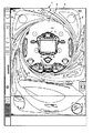
図1は、本実施例におけるパチンコ遊技機の正面図であり、主要部材の配置レイアウトを示す。パチンコ遊技機(遊技機)1は、大別して、遊技盤面を構成する遊技盤(ゲージ盤)2と、遊技盤2を支持固定する遊技機用枠(台枠)3とから構成されている。遊技盤2にはガイドレールによって囲まれた、ほぼ円形状の遊技領域が形成されている。この遊技領域のほぼ中央位置には、各々が識別可能な識別情報として特別図柄及び飾り図柄を可変表示可能に表示する可変表示装置4が設けられている。この可変表示装置4の下側には、普通可変入賞球装置(始動入賞口)6が配置されている。普通可変入賞球装置6の下側には、特別可変入賞球装置(大入賞口)7が配置されている。また、可変表示装置4の上部には、普通図柄表示器40が設けられている。
【0023】
可変表示装置4は、例えばLCD等からなり、普通可変入賞球装置6に遊技球が入賞することが実行条件となる可変表示ゲーム(特図ゲーム)において、数字、文字、図柄から構成され、各々が識別可能な複数種類の識別情報として機能する表示図柄を、複数の可変表示領域にて可変表示可能に表示する。図2は、可変表示装置4における画像表示例を示す図である。図2(A)に示す例では、可変表示装置4上に、3つの可変表示部4a〜4cが配置され、各可変表示部4a〜4cにおいて左・中・右の特別図柄が可変表示されるものとする。また、図2(B)に示す例では、可変表示部4a〜4cにおける特別図柄が可変表示装置4での表示画面左上端部にて縮小表示される。そして、可変表示部4a〜4cにおける特別図柄の縮小と移動に伴ってできた表示領域に、画像表示エリア41と、台詞表示エリア42とが配置される。
【0024】
可変表示装置4により行われる特図ゲームでは、特別図柄の可変表示を開始した後、一定時間が経過すると、特別図柄の表示結果を所定の順序で導出表示し、確定図柄(最終停止図柄)を停止表示する。そして、確定図柄の組合せが所定の特定表示結果(大当り組合せ)となったときに、このパチンコ遊技機1は、特定遊技状態(大当り遊技状態ともいう)となる。この大当り遊技状態においては、特別可変入賞球装置7が所定期間(例えば、29秒)あるいは所定個数(例えば、10個)の入賞球が発生するまで開成され、開成されている間、遊技盤2の表面を落下する遊技球を受け止める。そして、この開成サイクルを所定の上限回数(例えば、16回)まで繰り返すことができる。
【0025】
図3は、この実施の形態で用いられる特別図柄の例を示す図である。この実施の形態では、左可変表示部4aに特別図柄として表示される左図柄、中可変表示部4bに特別図柄として表示される中図柄、右可変表示部4cに特別図柄として表示される右図柄は、それぞれ9図柄であり、各図柄には「1」〜「9」の図柄番号が付されている。例えば、左・中・右の各可変表示部4a〜4cでは、特図ゲーム中に特別図柄の可変表示が開始されると、図柄番号が小さい特別図柄から大きい特別図柄へと更新表示が行われ、図柄番号が「9」の特別図柄が表示されると、次に図柄番号が「1」の特別図柄が表示される。
【0026】
この実施の形態では、図柄番号が偶数である特別図柄を通常大当り図柄とし、図柄番号が奇数である特別図柄を確変大当り図柄とする。すなわち、可変表示装置4による特図ゲームにおいて、特別図柄の可変表示を開始した後、左・中・右の各可変表示部4a〜4cにて同一の特別図柄が表示結果として導出表示されて確定したときには、パチンコ遊技機1は、大当り遊技状態となる。また、可変表示装置4による特図ゲームにおいて、特別図柄の可変表示を開始した後、左・中・右の各可変表示部4a〜4cにて同一の確変大当り図柄が表示結果として導出表示されて確定したときには、パチンコ遊技機1は大当り遊技状態の終了に続いて特別遊技状態(確率向上状態)となり、以後、所定条件が成立するまで特図ゲームにおける表示結果が大当り組合せとなる確率が向上する。また、確率向上状態では、普通可変入賞球装置6の開放時間が通常遊技状態よりも長くなるとともに、その開放回数が通常遊技状態のときよりも増加するなど、大当り遊技状態とは異なる遊技者にとって有利な状態となる。なお、通常遊技状態とは、大当り遊技状態や確率向上状態以外の遊技状態のことである。
【0027】
普通図柄表示器40は、発光ダイオード(LED)等を備えて構成され、遊技領域に設けられた通過ゲートを遊技球が通過することを始動条件とする普通図ゲームにおいて、点灯、点滅、発色などが制御される。この普通図ゲームにおいて所定の当りパターンで表示が行われると、普通図ゲームにおける表示結果が「当り」となり、普通可変入賞球装置6を構成する電動チューリップの可動翼片を所定時間が経過するまで傾動制御する。
【0028】
普通可変入賞球装置6は、ソレノイド21(図5)によって垂直(通常開放)位置と傾動(拡大開放)位置との間で可動制御される一対の可動翼片を有するチューリップ型役物(普通電動役物)5を備えて構成される。普通可変入賞球装置6への遊技球の入賞に基づく特別図柄及び飾り図柄の可変表示は、所定回数(本実施形態では、4回)まで後述する特図保留メモリ120(図7)に記憶される。
【0029】
特別可変入賞球装置7は、ソレノイド22(図5)によって入賞領域を開成・閉成制御する開閉板を備える。この開閉板は、通常時には閉成し、普通可変入賞球装置6への遊技球の入賞に基づいて可変表示装置4による特図ゲームが行われた結果、大当り遊技状態となった場合に、ソレノイド22によって入賞領域を所定期間(例えば、29秒)あるいは所定個数(例えば、10個)の入賞球が発生するまで開成(開成サイクル)する状態となるように設定され、その開成している間に遊技領域を落下する遊技球を受け止める。そして、この開成サイクルを例えば最高16回繰り返すことができるようになっている。特別可変入賞球装置7に入賞した遊技球は、所定の検出部により検出される。入賞球の検出に応答し、後述する主基板11と払出制御基板15(図4)とにより、所定数の賞球の払い出しが行われる。
【0030】
また、遊技盤2の表面には、上記した構成以外にも、ランプを内蔵した風車、アウト口等が設けられている。また、パチンコ遊技機1には、点灯又は点滅する遊技効果ランプ9や効果音を発生するスピーカ8L、8Rが設けられている。
【0031】
図4は、パチンコ遊技機1の背面図であり、主要基板の配置レイアウトを示す。本実施例におけるパチンコ遊技機1は、主として、電源基板10と、主基板11と、表示制御基板12と、音声制御基板13と、ランプ制御基板14と、払出制御基板15と、情報端子基板16とを備え、それぞれ適所に配設されている。なお、表示制御基板12、音声制御基板13及びランプ制御基板14は、それぞれ独立した基板として、例えば、パチンコ遊技機1の裏面において、1つのボックスに収容された状態で配置されてもよい。さらに、表示制御基板12、音声制御基板13及びランプ制御基板14を、まとめて1つの基板として構成してもよい。
【0032】
電源基板10は、パチンコ遊技機1内の各回路に所定の電源電圧を供給するものである。
【0033】
主基板11は、メイン側の制御基板であり、パチンコ遊技機1における遊技の進行を制御するための各種回路が搭載されている。主基板11は、主として、可変表示ゲームにおいて用いる乱数の生成機能、所定位置に配設されたスイッチ等からの信号の入力を行う機能、表示制御基板12、音声制御基板13、ランプ制御基板14及び払出制御基板15などからなるサブ側の制御基板に対して、それぞれ指令情報の一例となる制御コマンドを出力して送信する機能、ホールの管理コンピュータに対して各種情報を出力する機能などを備えている。
【0034】
主基板11から表示制御基板12へ送信される制御コマンドは表示制御コマンドである。図5は、主基板11における回路構成、及び主基板11から表示制御基板12に送信される表示制御コマンドの信号線を示すブロック図である。図5に示すように、この実施の形態では、表示制御コマンドが、表示制御信号CD0〜CD7の8本の信号線で主基板11から表示制御基板12に対して送出される。また、主基板11と表示制御基板12との間には、ストローブ信号を送受するための表示制御INT信号の信号線も配線されている。
【0035】
図6(A)は、この実施の形態で用いられる主基板11から表示制御基板12に対して送出される表示制御コマンドの内容の一例を示す説明図である。表示制御コマンドは2バイト構成であり、1バイト目はMODE(コマンドの分類)を表し、2バイト目はEXT(コマンドの種類)を表す。MODEデータの先頭ビットは必ず「1」とされ、EXTデータの先頭ビットは「0」とされる。なお、図6(A)に示されたコマンド形態は一例であって、他のコマンド形態を用いてもよい。また、この例では、制御コマンドが2つの制御信号で構成されることになるが、制御コマンドを構成する制御信号数は、1であってもよいし、3以上の複数であってもよい。
【0036】
図6(A)に示す例において、コマンド80XX(h)は、可変表示装置4における特別図柄の可変表示の開始を指令する可変表示開始コマンドである。なお、以下では、XX(h)が不特定の16進数であることを示し、表示制御コマンドによる指示内容に応じて任意に設定される値であるものとする。表示制御基板12の側では、可変表示開始コマンドに含まれるEXTデータに対応して、特別図柄の総可変表示時間、可変表示の表示結果が特定表示結果になるか否かの判定結果やリーチとするか否かの判定結果などを特定することができる。
【0037】
コマンド91XX(h)、92XX(h)、及び93XX(h)は、特別図柄の左・中・右確定図柄を指定する図柄指定コマンドである。各図柄指定コマンドでは、XX(h)に特別図柄の図柄番号が設定される。また、コマンドA000(h)は、特別図柄の可変表示の停止を指示する特別図柄確定コマンドである。コマンドB0XX(h)は、リーチとなる可能性があること、または大当りとなる可能性があることを報知するための予告演出を複数回の特図ゲームにわたり連続して行う連続予告を実行するときに、予告演出が連続して行われる特図ゲームの実行回数(可変表示回数)を指示するための連続予告回数指定コマンドである。連続予告コマンドでは、図6(B)に示すように、EXTデータXX(h)により、連続予告の実行回数が指定される。
【0038】
主基板11には、図5に示すように、始動入賞口である普通可変入賞球装置6や、大入賞口である特別可変入賞球装置7、その他の入賞口への遊技球の入賞等を検出するための各入賞口スイッチ70からの配線も接続されている。さらに、主基板11には、普通可変入賞球装置6における可動翼片の可動制御や特別可変入賞球装置7における開成・閉成制御を行うためのソレノイド21、22への配線が接続されている。
【0039】
主基板11は、遊技制御用マイクロコンピュータ100、スイッチ回路107、ソレノイド回路108などを搭載して構成される。遊技制御用マイクロコンピュータ100は、例えば1チップマイクロコンピュータであり、ゲーム制御用のプログラム等を記憶するROM(Read Only Memory)101、ワークメモリとして使用されるRAM(Random Access Memory)102、プログラムに従って制御動作を行うCPU(Central Processing Unit)103及びI/O(Input/Output)ポート104を含んでいる。
【0040】
また、遊技制御用マイクロコンピュータ100は、図7に示すように、特図保留メモリ120と、ランダムカウンタ121と、判定テーブルメモリ122と、図柄決定用テーブルメモリ123と、可変表示パターンテーブルメモリ124と、フラグメモリ125と、連続予告回数メモリ126と、連続予告カウンタ127と、可変表示時間タイマ128とを備えている。
【0041】
特図保留メモリ120は、遊技球が普通可変入賞球装置6に入賞して特別図柄の可変表示(特図ゲーム)を実行するための条件(実行条件)が成立したが、従前の可変表示を実行中である等の理由のために可変表示を実際に開始するための条件(開始条件)が成立していない保留状態を記憶するためのメモリである。図7に示す特図保留メモリ120では、4つのエントリが設けられており、各エントリには、普通可変入賞球装置6への入賞順に、保留番号と、その入賞に応じて抽出された乱数値(後述するランダムR1の値)と、後述する大当り・連続予告判定処理(図30)にて実行される大当り判定処理での判定結果である大当りフラグの設定を示すデータとが、対応付けて格納される。主基板11から表示制御基板12に対して特別図柄確定コマンドA000(h)が送出されて特別図柄の可変表示が1回終了したり、大当り遊技状態が終了したりするごとに、最上位の情報に基づいた可変表示の開始条件が成立し、最上位の情報に基づいた可変表示が実行される。このとき、第2位以下の登録情報が1位ずつ繰り上がる。また、特別図柄の可変表示中等に遊技球が普通可変入賞球装置6に新たに入賞した場合には、その入賞による乱数値が最上位の空エントリに登録される。
【0042】
ランダムカウンタ121は、遊技制御に用いられる判定用乱数や表示用乱数のカウントを行うものである。図8は、ランダムカウンタ121によりカウントされる各乱数を示す説明図である。ランダムカウンタ121は、図8に示すように、ランダムR1〜R6のカウントを行う。ランダムR1は、大当りを発生させてパチンコ遊技機1を特定遊技状態とするか否かを決定する大当り判定用の乱数であり、「0」〜「299」の範囲の値をとる。ランダムR2は、ハズレ時にリーチとするか否かを決定するリーチ判定用の乱数であり、「0」〜「1530」の範囲の値をとる。ランダムR3は、特別図柄の可変表示に用いる可変表示パターンを決定するための表示用の乱数であり、「0」〜「149」の範囲の値をとる。ランダムR4−1は、大当り時における特別図柄の確定図柄と、ハズレ時に左図柄における確定図柄とを、決定する乱数であり、「0」〜「106」の範囲の値をとる。ランダムR4−2は、ハズレ時に中図柄における確定図柄を決定する乱数であり、「0」〜「162」の範囲の値をとる。ランダムR4−3は、リーチとしない通常ハズレ時に右図柄における確定図柄を決定する乱数であり、「0」〜「72」の範囲の値をとる。
【0043】
ランダムR5は、パチンコ遊技機1を大当り遊技状態とした後に確率向上状態へと移行する確率変動制御(確変制御)を行うか否かを決定するための乱数であり、「0」〜「9」の範囲の値をとる。ランダムR6は、可変表示装置4による複数回の特図ゲームにおいて、連続予告を実行するか否かを決定するための乱数であり、「0」〜「999」の範囲の値をとる。ここで、連続予告は、特図保留メモリ120における保留記憶数を上限として、可変表示装置4による複数回の特図ゲームにて、大当りとなる可能性があること、またはリーチとなる可能性があることを報知するために行われる。
【0044】
図7に示す判定テーブルメモリ122は、CPU103が各種の判定を行うために設定される複数の判定テーブルを記憶する。具体的には、判定テーブルメモリ122は、図9(A)に示す通常時大当り判定テーブル140、図9(B)に示す確変時大当り判定テーブル141、図10(A)に示すハズレ時連続予告判定テーブル142、図10(B)に示す大当り時連続予告判定テーブル143を格納する。
【0045】
図9(A)に示す通常時大当り判定テーブル140と、図9(B)に示す確変時大当り判定テーブル141は、可変表示装置4による特図ゲームの表示結果を大当りとするか否かを判定するためのテーブルである。各大当り判定テーブル140、141では、ランダムR1の値と特図ゲームの表示結果を示す設定データとが対応付けて格納されている。そして、確変時大当り判定テーブル141では、通常時大当り判定テーブル140に比べてより多くのランダムR1の値が、「大当り」の表示結果と対応付けられている。すなわち、確変時大当り判定テーブル141を用いて特図ゲームの表示結果を決定することで、通常遊技状態のときよりも大当り遊技状態となる確率が高い確率向上状態とすることができる。
【0046】
図10(A)に示すハズレ時連続予告判定テーブル142と、図10(B)に示す大当り時連続予告判定テーブル143は、連続予告を実行するか否かを判定するためのテーブルである。各連続予告判定テーブル142、143では、連続予告の実行回数を示す設定データと、ランダムR6の値と、連続予告を実行するか否かの判定結果を示す設定データとが、対応付けて格納されている。
【0047】
ここで、ハズレ時連続予告判定テーブル142と、大当り時連続予告判定テーブル143とを比べると、連続予告の実行回数に応じて連続予告を実行するとの判定結果を示す設定データに対するランダムR6の割当が異なっている。すなわち、連続予告を実行する回数に応じて、連続予告の最後となる予告演出が行われた特図ゲームにおける表示結果が大当りとなるか否かの確率が異なるように、決定用データとしてのランダムR6の値が割り振られている。例えば、大当り時連続予告判定テーブル143では、図10(B)に示すように、連続予告を実行する回数が増加するに従って、連続予告を実行するとの判定結果に対して割り当てられるランダムR6の値の割合が高くなるように設定されている。このため、予告演出が連続して行われる特図ゲームの実行回数が増加するに従って、表示結果が大当りとなる確率が高くなる。
【0048】
図7に示す図柄決定用テーブルメモリ123は、可変表示装置4にて可変表示される特別図柄の確定図柄を決定するために用いられる複数種類の図柄決定用テーブルを記憶する。具体的には、図柄決定用テーブルメモリ123は、図11(A)に示す通常大当り図柄決定用テーブル144、図11(B)に示す確変大当り図柄決定用テーブル145、図12(A)に示す左図柄決定用テーブル146、図12(B)に示す中図柄決定用テーブル147、及び図12(C)に示す右図柄決定用テーブル148を格納する。
【0049】
図11(A)に示す通常大当り図柄決定用テーブル144は、特図ゲームの表示結果として左・中・右で同一の通常大当り図柄を導出表示するときに、各々の特別図柄の確定図柄を決定するためのテーブルである。例えば、通常大当り図柄決定用テーブル144には、確定図柄として選択決定される通常大当り図柄としての特別図柄の図柄番号と、ランダムR4−1の値とが対応付けて格納されている。
【0050】
図11(B)に示す確変大当り図柄決定用テーブル145は、特図ゲームの表示結果として左・中・右で同一の確変大当り図柄を導出表示するときに、各々の特別図柄の確定図柄を決定するためのテーブルである。例えば、確変大当り図柄決定用テーブル145には、確定図柄として選択決定される確変大当り図柄としての特別図柄の図柄番号と、ランダムR4−1の値とが対応付けて格納されている。
【0051】
図12(A)に示す左図柄決定用テーブル146は、特図ゲームにて大当りとすることなくハズレの表示結果を導出表示するときに、左可変表示部4aにおける確定図柄(左確定図柄)を決定するためのテーブルである。例えば、左図柄決定用テーブル146には、左可変表示部4aにおける確定図柄となる特別図柄の図柄番号と、ランダムR4−1の値とが対応付けて格納されている。
【0052】
図12(B)に示す中図柄決定用テーブル147は、ハズレの表示結果を導出表示するときに、中可変表示部4bにおける確定図柄(中確定図柄)を決定するためのテーブルである。例えば、中図柄決定用テーブル147には、左確定図柄の図柄番号に対する加算値と、ランダムR4−2の値とが対応付けて格納されている。すなわち、大当りとしないハズレ時には、ランダムカウンタ121から抽出されるランダムR4−2の値に基づき中図柄決定用テーブル147を用いて決定した加算値を、左図柄決定用テーブル146を用いて決定した左確定図柄の図柄番号に加算することで、中確定図柄を決めることができる。なお、リーチとした後に大当りとすることなくハズレの表示結果を導出表示するときに、中図柄決定用テーブル147を用いて決定された加算値が「0」である場合には、導出される表示結果をハズレとするために、中確定図柄の図柄番号を1加算するなどしてもよい。
【0053】
図12(C)に示す右図柄決定用テーブル148は、ハズレの表示結果を導出表示するときに、右可変表示部4cにおける確定図柄(右確定図柄)を決定するためのテーブルである。例えば、右図柄決定用テーブル148には、左確定図柄の図柄番号に対する加算値と、ランダムR4−3の値とが対応付けて格納されている。
【0054】
図7に示す可変表示パターンテーブルメモリ124は、特図ゲームで使用される複数の可変表示パターンを記憶する。具体的には、可変表示パターンテーブルメモリ124は、図13(A)に示す通常時可変表示パターンテーブル149、図13(B)に示すリーチ時可変表示パターンテーブル150、図13(C)に示す大当り時可変表示パターンテーブル151を格納する。
【0055】
図13(A)に示す通常時可変表示パターンテーブル149は、リーチとすることなくハズレの確定図柄を導出表示する可変表示パターンを選択するためのテーブルである。図13(B)に示すリーチ時可変表示パターンテーブル150は、リーチとした後に当りとすることなくハズレの確定図柄を導出表示する可変表示パターンを選択するためのテーブルである。図13(C)に示す大当り時可変表示パターンテーブル151は、特別図柄の可変表示における表示結果を大当りとするときに用いる可変表示パターンを選択するためのテーブルである。
【0056】
各可変表示パターンテーブル149〜151には、例えば、複数の可変表示パターンと、可変表示時間タイマ128が計測する特別図柄の総可変表示時間と、可変表示開始コマンドのEXTデータとして設定される制御コードとが対応付けて格納されている。すなわち、主基板11から表示制御基板12に対して送出される可変表示開始コマンドは、特別図柄の可変表示における可変表示パターンを、EXTデータにより指定する。また、表示結果をハズレとするか、大当りとするかに応じて、異なる可変表示パターンが用いられる。このため、表示制御基板12の側では、主基板11から送信された可変表示開始コマンドにより、特別図柄の可変表示における表示結果を特定表示結果とするか否かを特定することができる。また、リーチ時可変表示パターンテーブル150と、大当り時可変表示パターンテーブル151では、リーチB〜リーチDの可変表示パターンに対して決定用データとなるランダムR3の値が割り振られており、各可変表示パターンが所定の割合で選択決定可能に設定されている。
【0057】
通常時可変表示パターンテーブル149を用いて選択される通常A、通常Bの可変表示パターンは、リーチ表示態様を伴わない可変表示パターンである。リーチ時可変表示パターンテーブル150を用いて選択されるリーチA(ハズレ)〜リーチD(ハズレ)の可変表示パターンは、リーチ表示態様を伴うが可変表示結果(確定図柄)が大当りを生じさせるものとならない可変表示パターンである。他方、大当り時可変表示パターンテーブル151を用いて選択されるリーチA(大当り)〜リーチD(大当り)の可変表示パターンは、リーチ表示態様を伴い、可変表示結果が大当りを生じさせる可変表示パターンである。
【0058】
この実施の形態において、通常A(ハズレ)の可変表示パターンは、連続予告を実行するための設定がなされていないとき(後述する連続予告フラグがオフとなっているとき)に、リーチ表示態様とすることなくハズレの可変表示結果を導出表示する可変表示パターンである。通常B(ハズレ)の可変表示パターンは、連続予告を実行するための設定がなされたとき(連続予告フラグがオンとなっているとき)に、リーチ表示態様とすることなくハズレの可変表示結果を導出表示する可変表示パターンである。通常B(ハズレ)の可変表示パターンは、連続予告が行われた後の表示結果が大当りとなる可能性があることを報知するための予告演出として、可変表示装置4の表示領域に配置された画像表示エリア41に動画像を表示させる。
【0059】
また、リーチAの可変表示パターンは、連続予告の最後となる予告演出が行われる特図ゲームで使用される可変表示パターンであり、通常B(ハズレ)の可変表示パターンと同様に、可変表示装置4の表示領域に配置された画像表示エリア41に動画像を表示させる。ここで、リーチ時可変表示パターンテーブル150を用いて選択されるリーチA(ハズレ)の可変表示パターンは、リーチ表示態様を伴うが可変表示結果(確定図柄)が大当りを生じさせるものとならない可変表示パターンである。他方、大当り時可変表示パターンテーブル151を用いて選択されるリーチA(大当り)の可変表示パターンは、リーチ表示態様を伴い、可変表示結果が大当りを生じさせる可変表示パターンである。
【0060】
リーチB〜リーチDの可変表示パターンは、リーチAの可変表示パターンとは異なり、動画像による演出表示を行わない可変表示パターンである。リーチB〜リーチDの各可変表示パターンでは、リーチ表示態様が異なる。ここで、リーチ態様が異なるとは、リーチとなった後に異なる可変表示態様(特別図柄の可変表示速度や回転方向等)やキャラクタ等が現れることをいう。例えば、リーチBでは単に1種類の可変表示態様によってリーチ態様が実現されるのに対して、リーチCやリーチDでは、特別図柄の可変表示速度や回転方向が異なる複数の可変表示態様を含むリーチ態様が実現される。
【0061】
ここで、リーチ時可変表示パターンテーブル150と、大当り時可変表示パターンテーブル151とを比べると、リーチB〜リーチDの各可変表示パターン(リーチの種類)に対するランダムR3の値の割当が異なっている。すなわち、特図ゲームにおける表示結果が大当りとなるか否かに応じて、選択されるリーチ種類の割合が異なるものとなっている。これにより、特図ゲーム中に出現するリーチの種類に応じて、表示結果が大当りとなる確率は異なるものとなる。
【0062】
図13(B)及び図13(C)に示す例では、表示結果がリーチハズレとなる場合にリーチBの可変表示パターンが用いられる割合は、リーチDの可変表示パターンが用いられる割合よりも高くなっている。一方で、表示結果が大当りとなる場合にリーチBの可変表示パターンが用いられる割合は、リーチDの可変表示パターンが用いられる割合よりも低くなっている。このため、特図ゲーム中にリーチDの可変表示パターンによるリーチが出現した場合には、リーチAの可変表示パターンによるリーチが出現した場合よりも、表示結果が大当りとなる確率が高くなる。こうしたリーチの種類ごとに決められる表示結果が大当りとなる確率は、リーチの大当り信頼度、あるいは単に、リーチの信頼度と称される。
【0063】
図7に示すフラグメモリ125は、パチンコ遊技機1における遊技の進行を制御するために用いられる複数種類のフラグを設定するためのものである。例えば、フラグメモリ125には、特別図柄プロセスフラグ、普通図柄プロセスフラグ、大当りフラグ、確変フラグ、連続予告フラグ、リーチ状態フラグ、入力状態フラグ、エラーフラグ、タイマ割込フラグなどが設けられている。
【0064】
特別図柄プロセスフラグは、後述する特別図柄プロセス処理(図28)において、どの処理を選択・実行すべきかを指示する。普通図柄プロセスフラグは、普通図柄表示器40の表示状態を所定の順序で制御するために、所定の普通図柄プロセス処理においてどの処理を選択・実行すべきかを指示する。大当りフラグは、可変表示装置4による特図ゲームの表示結果が大当りとなるときにオン状態にセットされ、大当り遊技状態が終了するときにクリアされてオフ状態となる。確変フラグは、特図ゲームの表示結果となる特別図柄の確定図柄が、確変大当り図柄となるときにオン状態にセットされ、大当り遊技状態となる確率が向上した確率向上状態から通常遊技状態へ戻るときにクリアされてオフ状態となる。
【0065】
連続予告フラグは、ハズレ時連続予告判定テーブル142又は大当り時連続予告判定テーブル143を用いて連続予告を実行すると判定したときにオン状態にセットされ、連続予告の最後となる予告演出が行われる特図ゲームを実行するときにオフ状態にクリアされる。リーチ状態フラグは、可変表示装置4による特図ゲームにて特別図柄の可変表示中に表示態様をリーチ表示態様とすることが決定されたときに、オン状態にセットされる。
【0066】
入力状態フラグは、I/Oポート104に入力される各種信号の状態や各入賞口スイッチ70から入力される検出信号の状態等に応じて各々セットあるいはクリアさせる複数ビットからなるフラグである。エラーフラグは、パチンコ遊技機1において各種のエラーが発生したときに、発生したエラーの種類に対応するビットがセットされる複数ビットからなるフラグである。タイマ割込フラグは、所定時間が経過してタイマ割込みが発生するごとにオン状態にセットされる。
【0067】
連続予告回数メモリ126は、連続予告が行われる特図ゲームの実行回数をメイン側で記憶するためのものである。連続予告回数メモリ126には、連続予告を実行するか否かを判定するときに、特図保留メモリ120での保留記憶数に応じた連続予告の実行回数が設定される。連続予告カウンタ127は、今回の特図ゲームにて行われる予告演出が連続予告中の何回目に行われる予告演出に該当するかをメイン側でカウントするためのものである。すなわち、連続予告カウンタ127のカウント値は、連続予告の最初となる予告演出が行われる特図ゲームにて可変表示の開始条件が成立したときに初期値である「1」に設定され、以後、連続予告が行われる特図ゲームにて可変表示の開始条件が成立するごとに1加算される。
【0068】
可変表示時間タイマ128は、可変表示装置4による特図ゲームの実行時間である可変表示時間をメイン側で計測するためのダウンカウンタであり、主基板11から表示制御基板12に対して可変表示開始コマンドが送出されるに際して、可変表示パターンで指定される総可変表示時間に対応するカウント値が初期値として設定される。
【0069】
図5に示すスイッチ回路107は、各入賞口スイッチ70からの検出信号を取り込んで、遊技制御用マイクロコンピュータ100に伝達する。ソレノイド回路108は、遊技制御用マイクロコンピュータ100からの指令に従って各ソレノイド21、22を駆動する。ソレノイド21は、リンク機構を介して普通可変入賞球装置6の可動翼片に連結されている。ソレノイド22は、リンク機構を介して特別可変入賞球装置7の開閉板に連結されている。
【0070】
表示制御基板12は、主基板11とは独立して可変表示ゲームにおける画像処理のための表示制御などを行うものである。表示制御基板12は、主基板11から送出される表示制御コマンドに基づいて、可変表示ゲームに用いられる画像を可変表示装置4上に表示させるとともに、普通図柄表示器40の点灯/消灯制御を行う。
【0071】
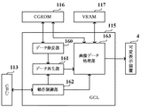
図14は、表示制御基板12のハードウェア構成例を示すブロック図である。表示制御基板12は、発振回路110と、リセット回路111と、表示制御用のCPU112と、ROM113と、RAM114と、GCL(Graphic Control LSI)115と、CGROM116と、VRAM(Video RAM)117とを備えている。
【0072】
発振回路110は、CPU112及びGCL115に基準クロック信号を出力するものであり、リセット回路111は、CPU112及びGCL115をリセットするためのリセット信号を出力するものである。CPU112は、主基板11から表示制御コマンドを受信するとRAM114を作業領域として用いながらROM113から表示制御を行うための制御データを読み出す。また、CPU112は、読み出した制御データに基づいてGCL115に描画命令を送る。ROM113は、CPU112によって利用される各種制御プログラム等を格納する半導体メモリであり、RAM114は、CPU112によって作業領域として利用される半導体メモリである。
【0073】
GCL115は、画像表示を行うための表示装置制御機能及び高速描画機能を有し、CPU112からの描画命令に従って動作する。また、CPU112とは独立した二次元のアドレス空間を持ち、そこにVRAM117をマッピングしている。GCL115は、CGROM116から読み出したデータに従って画像データを生成し、VRAM117上に展開する。そして、可変表示装置4に対してR(赤)、G(緑)、B(青)信号及び同期信号を出力する。例えば、R、G、B信号はそれぞれ8ビットで表され、可変表示装置4はGCL115からの指示に従ってR、G、Bのそれぞれを256階調、これらを合成して約1670万色の多色表示を行うことができる。なお、R、G、B信号のビット数は8ビット以外のビット数であってもよく、また、R、G、B信号の各ビット数が互いに異なる数であってもよい。
【0074】
また、GCL115は、図15に示すように、データ伸長部160と、データ再生部161と、動作制御部162と、画像データ処理部163とを備えている。データ伸長部160は、CGROM116に格納されている動画像データを伸長するためのものである。データ再生部161は、データ伸長部160により伸長された動画像データに基づいて生成される画像を可変表示装置4に順次表示させることによって動画再生を行うためのものである。動作制御部162は、CPU112からの描画命令などの指令に基づいて、GCL115の各部位における動作を制御するためのものである。画像データ処理部163は、可変表示装置4に動画像や静止画像、キャラクタ画像など、各種の画像を表示させるためのデータ処理を実行するためのものである。
【0075】
CGROM116は、可変表示装置4にて画像表示を行うための各種画像データを記憶しておくためのものである。具体的には、図16に示すように、CGROM116には、キャラクタ画像データ格納領域116a、動画像データ格納領域116b及び台詞画像データ格納領域116cが設けられている。
【0076】
キャラクタ画像データ格納領域116aには、可変表示装置4に表示される画像の中でも使用頻度の高いキャラクタ画像データ、具体的には、人物、動物、又は、文字、図形もしくは記号等が予め記憶されている。動画像データ格納領域116bには、実写によるものを含めた動画像や静止画像が、例えば動き補償符号化などのデジタル符号化方式によりデータ圧縮され、図17(A)に例示するような複数種類の動画像データとして記憶されている。図17(A)に示す例では、動画像データ格納領域116bに、動画像データ#1〜#16の16種類からなる画像データが格納されている。
【0077】
動画像データ格納領域116bに格納されている各動画像データは、図18に示すようなストリーム構成を有している。各動画像データは、例えば動画像による1単位の遊技演出の種類ごとに1つの動画像ファイルに格納されている。各動画像ファイルは、ファイルヘッダと、少なくとも1つのフレームヘッダ及びフレームごとの圧縮データとを含む。
【0078】
ここで、1フレーム分の圧縮データは、Iピクチャ、Pピクチャ、Bピクチャのいずれかに分類され、フレームヘッダには、いずれのピクチャの種類を識別するための情報や、各ピクチャの表示順序を指定する情報などが含まれている。Iピクチャは、フレーム内符号化によって符号化されているピクチャである。Pピクチャは、過去のフレームのみを用いて前方向の動き補償予測を行うピクチャである。Bピクチャは、過去及び未来の両方のフレームを用いて双方向の動き補償予測を行うピクチャである。
【0079】
台詞画像データ格納領域116cには、可変表示装置4の表示画面に配置された台詞表示エリア42に台詞となる文字列を表示するための文字列画像データが、図17(B)に示すように複数種類格納されている。
【0080】
また、表示制御基板12は、図19に示すように、ランダムカウンタ130と、表示制御プロセステーブルメモリ131と、予告パターン決定用テーブルメモリ132と、フラグメモリ133と、連続予告回数メモリ134と、連続予告カウンタ135と、各種タイマ136とを備えている。
【0081】
ランダムカウンタ130は、可変表示装置4による表示内容を決定するために用いられる乱数のカウントを行うためのものである。具体的には、ランダムカウンタ130は、図20に示すようなランダムR10のカウントを行う。ランダムR10は、後述する台詞表示制御プロセステーブルを決定するための乱数であり、「0」〜「99」の範囲の値をとる。
【0082】
図19に示す表示制御プロセステーブルメモリ131は、主基板11から受けた表示制御コマンドに基づいて選択される複数の表示制御プロセステーブルを記憶する。具体的には、表示制御プロセステーブルメモリ131は、図21(A)に示す動画像表示制御プロセステーブルメモリ131a、図21(B)に示す台詞表示制御プロセステーブルメモリ131b、図21(C)に示す図柄表示制御プロセステーブルメモリ131cを含んで構成される。
【0083】
図21(A)に示す動画像表示制御プロセステーブルメモリ131aは、複数種類の動画像表示制御プロセステーブルを格納する。各動画像表示制御プロセステーブルは、図22(A)に示すように、動画像表示プロセスタイマ設定値、動画像表示制御データなど、可変表示装置4の表示領域に配置された画像表示エリア41における動画像の表示状態を制御するためのデータからなり、時系列的にCGROM116の動画像データ格納領域116bにおける動画像データの読出位置やその動画像データによる動画像の再生時間、動画像の切替タイミング等が設定されている。
【0084】
図21(B)に示す台詞表示制御プロセステーブルメモリ131bは、複数種類の台詞表示制御プロセステーブルを格納する。各台詞表示制御プロセステーブルは、図22(B)に示すように、台詞表示プロセスタイマ設定値、台詞表示制御データなど、可変表示装置4の表示領域に配置された台詞表示エリア42における文字列画像の表示状態を制御するためのデータからなり、時系列的にCGROM116の台詞画像データ格納領域116cにおける文字列画像データの読出位置やその文字列画像データによる台詞の表示時間、文字列画像の切替タイミング等が設定されている。GCL115は、画像データ処理部163が台詞表示制御プロセステーブルに従った文字列画像データをCGROM116の台詞画像データ格納領域116cから読み出し、複数種類の文字列画像を順次生成して台詞表示エリア42に表示させることで、動画像と連動した台詞の更新表示を行うことができる。
【0085】
図21(C)に示す図柄表示制御プロセステーブルメモリ131cは、複数種類の図柄表示制御プロセステーブルを格納する。各図柄表示制御プロセステーブルは、図22(C)に示すように、図柄表示プロセスタイマ設定値、図柄表示制御データなど、特別図柄の表示状態を制御するためのデータからなり、時系列的に特別図柄の可変表示速度や表示する図柄の大きさ、その表示状態での表示期間、キャラクタの切替タイミング等が設定されている。
【0086】
予告パターン決定用テーブルメモリ132は、連続予告となる予告演出における動画像や文字列画像の表示態様を決定するために設定される複数種類のテーブルを、予告パターン決定用テーブルとして記憶する。具体的には、予告パターン決定用テーブルメモリ132は、図23に示す動画像表示手順決定テーブル170、図24に示す連続予告中台詞決定テーブル171、図25(A)に示すハズレ最終予告時台詞決定テーブル172、図25(B)に示す大当り最終予告時台詞決定テーブル173を格納する。
【0087】
図23に示す動画像表示手順決定テーブル170は、連続予告を実行しているときに、連続予告回数メモリ134に記憶された連続予告の実行回数、及び連続予告カウンタ135のカウント値に応じて、今回の特図ゲームにて使用する動画像表示制御プロセステーブルを選択決定できるように設定されている。すなわち、動画像表示手順決定テーブル170は、連続予告回数メモリ134に記憶されている連続予告の実行回数に対応する設定データ、連続予告カウンタ135のカウント値に対応する設定データ、及び選択決定する動画像表示制御パターンを、対応付けて格納する。
【0088】
図24に示す連続予告中台詞決定テーブル171は、連続予告を実行しているときに、連続予告回数メモリ134に記憶されている連続予告の実行回数、及び連続予告カウンタ135のカウント値に応じて、今回の特図ゲームにて使用する台詞表示制御プロセステーブルを選択決定できるように設定されている。すなわち、連続予告中台詞決定テーブル171は、連続予告回数メモリ134に記憶されている連続予告の実行回数に対応する設定データ、連続予告カウンタ135のカウント値に対応する設定データ、及び選択決定する台詞表示制御パターンを、対応付けて格納する。
【0089】
図25(A)及び図25(B)に示す各最終予告時台詞決定テーブル172、173は、連続予告の最後となる予告演出が行われる特図ゲームで使用する台詞表示制御プロセステーブルを、連続予告回数メモリ134に記憶されている連続予告の実行回数、及びランダムR10の値に応じて選択決定できるように設定されている。
【0090】
ここで、各最終予告時台詞決定テーブル172、173では、可変表示装置4の表示領域に配置された台詞表示エリア42に表示される文字列画像の種類に応じて特別図柄の可変表示結果が大当りとなる確率が異なるように、各台詞表示制御プロセステーブルに対して決定用データとしてのランダムR10の値が割り振られている。すなわち、ハズレ最終予告時台詞決定テーブル172と、大当り最終予告時台詞決定テーブル173とを比べると、各台詞表示制御プロセステーブルに対するランダムR10の値の割当が異なっており、特図ゲームにおいて連続予告が行われた後の表示結果が大当りとなるか否かに応じて、各台詞表示制御プロセステーブルの選択される確率が異なるように設定されている。
【0091】
図25に示す例では、2回の特図ゲームにわたり連続して予告演出を行った後にハズレの表示結果を導出表示するとき、2回目の予告演出が行われる特図ゲームで用いられる台詞表示制御プロセステーブルの割合は、台詞B−5、台詞B−4、台詞B−3の順番で、徐々に高くなるように設定されている。また、このときには台詞B−6の表示制御プロセステーブルが用いられることはない。その一方で、2回の特図ゲームにわたり連続して予告演出を行った後に大当りの表示結果を導出表示するとき、2回目の予告演出が行われる特図ゲームで用いられる台詞表示制御プロセステーブルの割合は、台詞B−3、台詞B−4、台詞B−5、台詞B−6の順番で、徐々に高くなるように設定されており、表示結果がハズレとなる場合とは逆の順番になっている。このため、2回の特図ゲームにわたり連続した予告演出が行われるときに、2回目の予告演出として台詞B−6の表示制御プロセステーブルに従った台詞としての文字列画像が台詞表示エリア42に表示されたときには、その後に導出表示される可変表示結果が必ず大当りとなる。また、2回目の予告演出として台詞B−5の表示制御プロセステーブルに従った台詞としての文字列画像が台詞表示エリア42に表示されたときには、台詞B−3に従った文字列画像が表示されたときよりも、表示結果が大当りとなる確率が高くなる。GCL115では、画像データ処理部163により台詞表示制御プロセステーブルに従った複数種類の文字列画像が順次生成されるので、特図ゲームの表示結果が大当りとなる確率に応じて表示態様が異なる文字列画像が生成されることとなる。
【0092】
図19に示すフラグメモリ133は、可変表示装置4における表示状態などに応じて各々セットあるいはクリアされる複数種類のフラグを設定するためのものである。例えば、フラグメモリ133には、表示制御プロセスフラグ、連続予告フラグ、フェードイン制御フラグ、フェードアウト制御フラグ、フェードイン表示状態フラグ、フェードアウト表示状態フラグ、タイマ割込フラグなどが設けられている。
【0093】
表示制御プロセスフラグは、後述する表示制御プロセス処理(図38)において、どの処理を選択・実行すべきかを指示する。連続予告フラグは、主基板11からの連続予告回数指定コマンドB0XX(h)により連続予告の実行回数が指定されたときにオン状態にセットされる。また、連続予告フラグは、連続予告カウンタ135のカウント値が連続予告回数メモリ134に記憶されている連続予告の実行回数と同一になったときに、クリアされてオフ状態となる。
【0094】
フェードイン制御フラグは、フェードイン表示を開始するタイミングにてオン状態にセットされる。フェードイン表示では、動画再生を開始するときに使用されるフレームデータの画像を段階的に出現させる。フェードアウト制御フラグは、フェードアウト表示を開始するタイミングにてオン状態にセットされる。フェードアウト表示では、動画再生の終了時におけるフレームデータの画像を段階的に消滅させる。フェードイン表示状態フラグは、フェードイン表示にて動画再生の開始時における画像が段階的に出現しているあいだ、オン状態にセットされる。フェードアウト表示状態フラグは、フェードアウト表示にて動画再生の終了時における画像が段階的に消滅しているあいだ、オン状態にセットされる。タイマ割込フラグは、所定時間が経過してタイマ割込みが発生するごとにオン状態にセットされる。
【0095】
連続予告回数メモリ134は、連続予告が行われる特図ゲームの実行回数をサブ側で記憶するためのものである。連続予告回数メモリ134には、主基板11からの連続予告回数指定コマンドB0XX(h)により指定された連続予告の実行回数を示す制御データが格納される。連続予告カウンタ135は、今回の特図ゲームにて行われる予告演出が連続予告中の何回目に行われる予告演出に該当するかをサブ側にてカウントするためのものである。すなわち、連続予告カウンタ135のカウント値は、EXTデータが00(h)以外である連続予告回数指定コマンドを主基板11から受けたときに初期値である「1」に設定され、以後、連続予告が行われる特図ゲームにて特別図柄の可変表示を開始するごとに1加算される。
【0096】
各種タイマ136は、可変表示装置4の表示制御に用いられる複数種類のタイマを含んで構成される。例えば、各種タイマ136は、動画像表示プロセスタイマ、台詞表示プロセスタイマ、図柄表示プロセスタイマ、可変表示時間タイマ及び監視タイマを含んでいる。動画像表示プロセスタイマは、動画像表示制御プロセステーブルメモリ131aから読み出された動画像表示制御プロセステーブルに設定されているプロセスタイマ値をカウントダウンすることにより、動画像表示制御プロセステーブルによって指定される動画像データに基づく再生画像を表示する期間を計測する。台詞表示プロセスタイマは、台詞表示制御プロセステーブルメモリ131bから読み出された台詞表示制御プロセステーブルに設定されているプロセスタイマ値をカウントダウンすることにより、台詞表示制御プロセステーブルによって指定される文字列画像データに基づく台詞を表示する期間を計測する。図柄表示プロセスタイマは、図柄表示制御プロセステーブルメモリ131cから読み出された図柄表示制御プロセステーブルに設定されているプロセスタイマ値をカウントダウンすることにより、特別図柄を図柄表示制御プロセステーブルに設定されている態様で可変表示させる期間を計測する。
【0097】
また、各種タイマ136に含まれる可変表示時間タイマは、特図ゲームの実行時間である可変表示時間をサブ側で計測するためのダウンカウンタである。監視タイマは、可変表示時間タイマがタイムアウトしてからの経過時間を計測するためのものであり、主基板11から表示制御コマンドを所定時間以上受信しなかったときにタイムアウトする。
【0098】
図4に示す音声制御基板13、ランプ制御基板14は、主基板11から送信される制御コマンドに基づいて、音声出力制御、ランプ出力制御を、それぞれ主基板11とは独立して実行するサブ側の制御基板である。払出制御基板15は、遊技球の貸出や賞球等の払出制御を行うものである。情報端子基板16は、各種の遊技関連情報を外部に出力するためのものである。
【0099】
次に、本実施例におけるパチンコ遊技機1の動作(作用)を説明する。図26は、主基板11に搭載された遊技制御用マイクロコンピュータ100が実行する遊技制御メイン処理を示すフローチャートである。主基板11では、電源基板10からの電源電圧が供給されると、遊技制御用マイクロコンピュータ100が起動し、CPU103が、まず、図26のフローチャートに示す遊技制御メイン処理を実行する。遊技制御メイン処理を開始すると、CPU103は、割込禁止に設定した後(ステップS11)、必要な初期設定を行う(ステップS12)。この初期設定では、例えば、RAM102がクリアされる。また、遊技制御用マイクロコンピュータ100に内蔵されたCTC(カウンタ/タイマ回路)のレジスタ設定を行うことにより、定期的(例えば、2ミリ秒ごと)にタイマ割込を発生させる。初期設定が終了すると、割込を許可した後(ステップS13)、ループ処理に入る。
【0100】
こうした遊技制御メイン処理の実行により、2ミリ秒ごとに繰り返しタイマ割込が発生するように設定され、タイマ割込が発生すると、CPU103は、図27のフローチャートに示す遊技制御割込処理を実行する。
【0101】
図27のフローチャートに示す遊技制御割込処理を開始すると、CPU103は、まず、所定のスイッチ処理を実行することにより、スイッチ回路107を介して各入賞口スイッチ70から入力される検出信号の状態を判定する(ステップS21)。続いて、所定のエラー処理を実行することにより、パチンコ遊技機1の異常診断を行い、その診断結果に応じて必要ならば警告を発生可能とする(ステップS22)。この後、ランダムカウンタ121によりカウントされる判定用乱数であるランダムR1を更新する判定用乱数更新処理(ステップS23)と、表示用乱数であるランダムR2を更新する表示用乱数更新処理(ステップS24)とを、順次に実行する。
【0102】
次に、CPU103は、特別図柄プロセス処理を実行する(ステップS25)。特別図柄プロセス処理では、遊技状態に応じてパチンコ遊技機1を所定の順序で制御するために、フラグメモリ125に設けられた特別図柄プロセスフラグに従って該当する処理が選択されて実行される。特別図柄プロセス処理に続いて、CPU103は、普通図柄プロセス処理を実行する(ステップS26)。普通図柄プロセス処理では、普通図柄表示器40を所定の順序で制御するために、所定の普通図柄プロセスフラグに従って該当する処理が選択されて実行される。
【0103】
さらに、CPU103は、所定のコマンド制御処理を実行することにより、主基板11から表示制御基板12等のサブ側の制御基板に対して制御コマンドを送出し、遊技状態に合わせた動作制御を指示する(ステップS27)。このコマンド制御処理により主基板11から送出された表示制御コマンドを表示制御基板12のCPU112が受け取り、その表示制御コマンドに従って可変表示装置4の表示制御や普通図柄表示器40の点灯/消灯制御などが行われる。
【0104】
また、CPU103は、所定の情報出力処理を実行することにより、各種出力データの格納領域の内容をI/Oポート104に含まれる各出力ポートに出力する(ステップS28)。この情報出力処理では、主基板11から情報端子基板16に、大当り情報、始動情報、確率変動情報などをホール管理用コンピュータに対して出力する指令の送出も行われる。
【0105】
続いて、CPU103は、所定のソレノイド出力処理を実行することにより、所定の条件が成立したときに普通可変入賞球装置6における可動翼片の可動制御や特別可変入賞球装置7における開閉板の開閉駆動を行う(ステップS29)。この後、所定の賞球処理を実行することにより、各入賞口スイッチ70から入力された検出信号に基づく賞球数の設定などを行い、払出制御基板15に対して払出制御コマンドを出力可能とする(ステップS30)。
【0106】
図28は、ステップS25にて実行される特別図柄プロセス処理を示すフローチャートである。特別図柄プロセス処理を開始すると、CPU103は、まず、遊技球が普通可変入賞球装置6に入賞したか否かを、各入賞口スイッチ70に含まれる始動球検出スイッチから入力される検出信号や、フラグメモリ125に設けられた入力状態フラグなどをチェックすることにより、判別する(ステップS100)。遊技球が入賞して始動球検出スイッチからの検出信号がオン状態となった場合(ステップS100;Yes)、入賞処理を実行し(ステップS101)、遊技球が入賞していない場合(ステップS100;No)、入賞処理をスキップする。
【0107】
ステップS101の入賞処理では、特図保留メモリ120の保留数が上限値の4以上であるか否かが判別され、保留数が4以上であれば、今回の入賞による特図ゲームの始動は無効として特に何も行わない。一方、保留数が上限値の4未満である場合には、保留記憶数を1加算するとともに、ランダムカウンタ121より大当り判定用のランダムR1の値を抽出し、抽出したランダムR1の値を特図保留メモリ120の空エントリの先頭にセットする。
【0108】
この後、CPU103は、フラグメモリ125に格納されている特別図柄プロセスフラグの値に基づいて、図28に示すステップS110〜S117の8個の処理のいずれかを選択する。以下に、ステップS110〜S117の各処理について説明する。
【0109】
ステップS110の特別図柄通常処理は、特別図柄プロセスフラグの値が初期値「0」のときに実行される処理である。この処理において、CPU103は、図29に示すように、まず、特図保留メモリ120が記憶している保留記憶数が「0」であるか否かを判別する(ステップS201)。ここで、特図保留メモリ120において、保留番号「1」に対応した乱数値等の各種データが記憶されていない場合には、保留記憶数が「0」であると判別される。保留記憶数が「0」であれば(ステップS201;Yes)、表示制御基板12を介して可変表示装置4上にデモンストレーション画面を表示するなどして、特別図柄通常処理を終了する。
【0110】
ステップS201において保留記憶数が「0」ではないと判別すると(ステップS201;No)、フラグメモリ125に設けられた連続予告フラグがオンとなっているか否かを判別する(ステップS202)。連続予告フラグがオフであるときには、図30のフローチャートに示す大当り・連続予告判定処理を実行する(ステップS203)。一方、連続予告フラグがオンであるときには、ステップS203をスキップして、ステップS204に進む。
【0111】
ステップS203にて大当り・連続予告判定処理を開始すると、CPU103は、特図保留メモリ120の記憶内容をチェックするために用いられる変数kの値を初期値「1」に設定する(ステップS301)。続いて、特図保留メモリ120において変数kの値と同一の保留番号に格納された設定データを読み取り、変数kの値と同一の保留番号に格納されたランダムR1の値に基づいた大当り判定が既に行われているか否かを判別する(ステップS302)。変数kの値と同一の保留番号で実行が保留されている特図ゲームの大当り判定が未だ行われていないとき(ステップS302;No)、CPU103は、図32のフローチャートに示す大当り判定処理を実行する(ステップS303)。一方、変数kの値に対応する保留記憶の大当り判定が既に行われているときには(ステップS302;Yes)、ステップS303をスキップして、ステップS304に進む。
【0112】
ステップS303にて大当り判定処理を開始すると、CPU103は、まず、フラグメモリ125に設けられた確変フラグがオンとなっているか否かを判別し(ステップS321)、オフとなっていれば(ステップS321;No)、通常遊技状態であると判断して、特図ゲームの表示結果を大当りとするか否かを判定するためのテーブルとして、図9(A)に示すような通常時大当り判定テーブル140を設定する(ステップS322)。これに対して、確変フラグがオンとなっていれば(ステップS321;Yes)、確率向上状態になっていると判断して、図9(B)に示すような確変時大当り判定テーブル141を設定する(ステップS323)。
【0113】
続いて、CPU103は、特図保留メモリ120にて変数kの値と同一の保留番号に格納されているランダムR1の値に基づき、ステップS322又はS323にて設定された大当り判定テーブル140又は141を用いて大当りとするか否かを決定する(ステップS324)。こうして実行条件が成立した可変表示の表示結果を大当り組合せとすることに決定したときには(ステップS324;Yes)、大当りフラグをオン状態にセットするための設定データを、特図保留メモリ120にて変数kと同一の保留番号に対応付けて格納する(ステップS325)。一方、表示結果をハズレとすることに決定したときには(ステップS324;No)、大当りフラグをオフ状態にセットするための設定データを、特図保留メモリ120にて変数kと同一の保留番号に対応付けて格納する(ステップS326)。こうして大当り判定処理を終了すると、図30に示すステップS304に進む。
【0114】
ステップS304において、CPU103は、変数kの値が「1」であるか否かを判別する。変数kが「1」以外の値であれば(ステップS304;No)、特図保留メモリ120にて変数kの値と同一の保留番号に格納された設定データが特図ゲームの表示結果を大当りとするものであるか否かを判別する(ステップS305)。すなわち、変数kの値と同一の保留番号に格納された大当りフラグの設定データが、大当りフラグをオンに設定するためのものである否かを判別する。
【0115】
ステップS305にて変数kの値と同一の保留番号に格納された設定データがハズレを指定するとき(ステップS305;No)、CPU103は、変数kの値を1加算して更新し(ステップS306)、更新された変数kの値と同一の保留番号に対応した保留記憶があるか否かを判別する(ステップS307)。このとき、特図保留メモリ120にて変数kの値と同一の保留番号に対応付けてランダムR1の値が格納されていれば、保留記憶があるものとして判別する。変数kの値と同一の保留番号に対応する保留記憶があるときには(ステップS307;Yes)、ステップS302にリターンして、次の保留番号に対応する記憶内容に基づく大当り判定などを行う。
【0116】
また、ステップS307にて変数kの値と同一の保留番号に対応する保留記憶がないとき(ステップS307;No)、CPU103は、変数kの値が「3」以上であるか否かを判別し(ステップS308)、「3」未満であるときには(ステップS308;No)、連続予告設定処理を終了する。
【0117】
ステップS305にて変数kの値と同一の保留番号に格納された設定データが大当りを指定するとき(ステップS305;Yes)、CPU103は、連続予告回数メモリ126に変数kの値をセットする(ステップS309)。こうして大当りを指定する設定データが格納された保留番号と同一の変数kの値を連続予告回数メモリ126にセットすることにより、特図保留メモリ120の記憶内容に基づいてステップS303の大当り判定処理で表示結果を大当りにすると判定されるまでの判定回数を特定することができる。
【0118】
ステップS309に続いて、CPU103は、連続予告を実行するか否かを判定するためのテーブルとして、図10(B)に示す大当り時連続予告判定テーブル143を設定する(ステップS310)。また、ステップS308にて変数kの値が「3」以上であるときには(ステップS308;Yes)、変数kの値から1減算した値を連続予告回数メモリ126にセットする(ステップS311)。これにより、特図保留メモリ120における保留記憶数と同一の値が連続予告回数メモリ126にセットされて、特図保留メモリ120の保留記憶数に対応して実行されたステップS303の大当り判定処理における大当りとするか否かの判定回数を特定することができる。
【0119】
ステップS311に続いて、CPU103は、連続予告を実行するか否かを判定するためのテーブルとして、図10(A)に示すハズレ時連続予告判定テーブル142を設定する(ステップS312)。ステップS310又はS312を実行した後、CPU103は、ランダムカウンタ121よりランダムR6の値を抽出し(図31に示すステップS313)、抽出されたランダムR6の値と連続予告回数メモリ126に格納されている連続予告を実行する場合の実行回数とに基づき、ステップS310又はS312にて設定した連続予告判定テーブル142又は143を用いて連続予告を実行するか否かの判定を行う(ステップS314)。
【0120】
ここで、図10(A)に示すハズレ時連続予告判定テーブル142、及び図10(B)に示す大当り時連続予告判定テーブル143を用いることで、連続予告としての予告演出が行われる特図ゲームの実行回数(可変表示回数)に応じて、図33(A)に示すような確率で連続予告を実行すると判定されることとなる。すなわち、この実施の形態では、保留記憶数が「2」で全てハズレの表示結果となるとき、保留記憶数が「3」で全てハズレの表示結果となるとき、保留記憶数が「4」で全てハズレの表示結果となるときに、いずれも1/1000の確率で連続予告が実行される。また、保留番号「2」に大当りとする設定データが格納されているときには1/10の確率で2回の特図ゲームにわたる連続予告が実行され、保留番号「3」に大当りとする設定データが格納されているときには2/5の確率で3回の特図ゲームにわたる連続予告が実行され、保留番号「4」に大当りとする設定データが格納されているときには19/20の確率で4回の特図ゲームにわたる連続予告が実行される。
【0121】
図33(B)は、連続予告としての予告演出が行われる特図ゲームの実行回数に応じた大当り信頼度を示す説明図である。なお、図33(B)に示す大当り信頼度は、各可変表示における大当りとなる確率を示す大当り確率が1/300であるとして算出されたものである。図33(B)に示すように、連続予告が2回の特図ゲームにわたり行われたあとの可変表示結果が大当りとなる確率は1/4であり、連続予告が3回の特図ゲームにわたり行われたあとの可変表示結果が大当りとなる確率は4/7であり、連続予告が4回の特図ゲームにわたり行われたあとの可変表示結果が大当りとなる確率は19/25である。すなわち、本例では、複数回の特図ゲームにおいて連続して予告演出が行われるときには、より多くの特図ゲームにわたって連続して予告演出が行われるほど、可変表示結果が大当りとなる確率が高くなる。
【0122】
ステップS314にて連続予告を実行しないと判定したときには(ステップS314;No)、連続予告回数メモリ126の記憶内容をクリアする(ステップS315)。また、このときには、表示制御基板12に対して「連続予告指定なし」を示す連続予告回数指定コマンドB000(h)を送出するための設定を行う(ステップS316)。具体的には、連続予告回数指定コマンドB000(h)に対応する制御データを、所定のコマンド送信テーブルに設定するなどして、連続予告回数指定コマンドを表示制御コマンドとして表示制御基板12に対し送出可能に設定する。
【0123】
これに対して、ステップS314にて連続予告を実行すると判定したときには(ステップS314;Yes)、フラグメモリ125に設けられた連続予告フラグをオン状態にセットするとともに、連続予告カウンタ127に「1」をセットする(ステップS316)。また、このときには、表示制御基板12に対して連続予告の実行回数を指定するための連続予告回数指定コマンドB0XX(h)を送出するための設定を行う(ステップS318)。すなわち、連続予告回数メモリ126に記憶されている連続予告の実行回数に基づいて連続予告回数指定コマンドのEXTデータを設定し、所定のコマンド送信テーブルに格納するなど、表示制御基板12に対して送出可能に設定する。このようにして大当り・連続予告判定処理を終了すると、図29に示すステップS204に進む。
【0124】
ステップS204において、CPU103は、特図保留メモリ120から保留番号「1」に対応して格納されている乱数値等の各種データを読み出す。この際、特図保留メモリ120における保留記憶数を1減算し、かつ、第2〜第4エントリ(保留番号「2」〜「4」)に格納されたデータを1エントリずつ上位にシフトする(ステップS205)。そして、ステップS204にて読み出した設定データに基づいて、フラグメモリ125に設けられた大当りフラグをオン状態にセット、あるいはクリアしてオフ状態とする設定を行う(ステップS206)。この後、特別図柄プロセスフラグの値を確定図柄設定処理に対応した値である「1」に更新する(ステップS207)。
【0125】
なお、ステップS204において特図保留メモリ120からのデータ読出を行った後に、読み出したランダムR1の値に基づき、図32のフローチャートに示すものと同様の大当り判定モジュールにより、可変表示結果を大当りとするか否かの判定を行うようにしてもよい。このときには、大当り判定モジュールによる判定結果と、特図保留メモリ120から読み出した大当りフラグの設定データとを比較するなどして、特図保留メモリ120における記憶内容が適正であるか否かを判定するようにしてもよい。また、フラグメモリ125に設けられた確変フラグがオン状態となっているときには、上述したステップS203の大当り・連続予告判定処理をスキップして、ステップS204においてデータ読出を行った後に、大当り判定モジュールにより可変表示結果を大当りとするか否かの判定を行うようにしてもよい。これにより、特図保留メモリ120により実行が保留されている全ての特図ゲームについて可変表示の開始条件が成立するよりも前に確率向上状態が終了してしまうような場合(例えば確率向上状態において実行可能な特図ゲームの残り可変表示回数が「2」である一方で、特図保留メモリ120における保留記憶数が「3」であるような場合)に、ステップS303の大当り判定処理において、本来であれば通常時大当り判定テーブル140を用いて大当り判定を行わなければならない保留記憶について、確変フラグがオン状態となっていることから、確変時大当り判定テーブル141を用いて大当り判定が行われてしまうといった不都合を、回避することができる。
【0126】
図28に示すステップS111の確定図柄設定処理は、特別図柄プロセスフラグの値が「1」のときに実行される処理である。この処理において、CPU103は、図34に示すように、まず、フラグメモリ125に設けられた大当りフラグがオンとなっているか否かを判別する(ステップS221)。大当りフラグがオフであるときには(ステップS221;Yes)、さらに連続予告フラグがオンとなっているか否かを判別する(ステップS222)。連続予告フラグがオフであるときには(ステップS222;No)、ランダムカウンタ121よりランダムR2の値を抽出し(ステップS223)、リーチとするか否かを決定する(ステップS224)。例えば、ステップS223にて抽出したランダムR2の値が「105」〜「1530」のいずれかであるときには、リーチとしないことを決定し、「0」〜「104」のいずれかであるときには、リーチとすることを決定する。また、フラグメモリ125に設けられた確変フラグがオンとなっているか否かに応じてリーチとするランダムR2の値が異なるテーブルを用意しておき、確変フラグの状態に応じて選択したテーブルを用いてリーチとするか否かを決定してもよい。
【0127】
ステップS224にてリーチとしないことを決定したとき(ステップS224;No)、CPU103は、フラグメモリ125に設けられたリーチ状態フラグをクリアしてオフ状態とする(ステップS225)。そして、ランダムカウンタ121より抽出したランダムR4−1の値に基づき、図12(A)に示す左図柄決定用テーブル146を用いて左確定図柄を決定する(ステップS226)。また、ランダムカウンタ121より抽出したランダムR4−2の値に基づき、図12(B)に示す中図柄決定用テーブル147を用いて中確定図柄を決定するとともに(ステップS227)、ランダムカウンタ121より抽出したランダムR4−3の値に基づき、図12(C)に示す右図柄決定用テーブル148を用いて右確定図柄を決定する(ステップS228)。この後、ステップS242に進む。
【0128】
また、ステップS224にてリーチとすることを決定したとき(ステップS224;Yes)、CPU103は、リーチ状態フラグをオン状態にセットし(ステップS229)、ランダムカウンタ121より抽出したランダムR4−1の値に基づき、左図柄決定用テーブル146を用いて左確定図柄を決定する(ステップS230)。また、左確定図柄と同一の図柄番号である特別図柄を右確定図柄とすることを決定し(ステップS231)、左・右確定図柄とは異なる任意の特別図柄を中確定図柄とすることを決定する(ステップS232)。この後、ステップS242に進む。
【0129】
上述したステップS222にて連続予告フラグがオンであると判別したとき(ステップS222;Yes)、CPU103は、連続予告カウンタ127のカウント値が、連続予告回数メモリ126に記憶されている連続予告の実行回数に一致するか否かを判別する(ステップS233)。ここで、連続予告の最後となる予告演出が行われる特図ゲームの開始条件が成立したときには、連続予告カウンタ127のカウント値が連続予告回数メモリ126に記憶されている連続予告の実行回数に等しくなる。ステップS233にて連続予告カウンタ127のカウント値が連続予告の実行回数と同一であると判別したときには(ステップS233;Yes)、上述したステップS229に進み、リーチ表示態様とするための設定を行う。一方、ステップS233にて連続予告カウンタ127のカウント値が連続予告の実行回数とは異なると判別したときには(ステップS233;No)、上述したステップS225に進み、リーチ表示態様とすることなくハズレの可変表示結果を導出表示するための設定を行う。このように、連続予告が行われた後の可変表示結果がハズレとなるときには、リーチ表示態様とした後にハズレの表示結果が導出表示されることとなる。また、連続予告の最終回以外とされる予告演出が行われる特図ゲームでは、リーチ表示態様とすることなくハズレの表示結果が導出表示されることとなる。
【0130】
上述したステップS221にて大当りフラグがオンであると判別したとき(ステップS221;Yes)、CPU103は、ランダムカウンタ121よりランダムR5の値を抽出し(図35に示すステップS234)、大当り遊技状態が終了した後に確率向上状態へと移行する確率変動制御を行うか否かを決定する(ステップS235)。例えば、ランダムカウンタ121より抽出したランダムR5の値が奇数であるときには確率変動制御を行うことを決定し、偶数であるときには確率変動制御を行わないことを決定する。
【0131】
ステップS235にて確率変動制御を行わないことを決定したとき(ステップS235;No)、CPU103は、フラグメモリ125に設けられた確変フラグをクリアしてオフ状態とし(ステップS236)、大当りの可変表示結果となる特別図柄の確定図柄を決定するためのテーブルとして、図11(A)に示す通常大当り図柄決定用テーブル144を設定する(ステップS237)。また、ステップS235にて確率変動制御を行うことを決定したときには(ステップS235;Yes)、確変フラグをオン状態にセットするとともに(ステップS238)、特別図柄の確定図柄を決定するためのテーブルとして、図11(B)に示す確変大当り図柄決定用テーブル145を設定する(ステップS239)。
【0132】
ステップS237又はS239を実行した後、CPU103は、ランダムカウンタ121よりランダムR4−1の値を抽出し(ステップS240)、抽出されたランダムR4−1の値に基づき、ステップS237又はS239にて設定した図柄決定用テーブル144又は145を用いて左・中・右で同一となる大当り用の確定図柄を決定する(ステップS241)。この後、図34に示すステップS242に進む。ステップS242において、CPU103は、特別図柄プロセスフラグの値を可変表示パターン設定処理に対応した値である「2」に更新して、確定図柄設定処理を終了する。
【0133】
図28に示すステップS112の可変表示パターン設定処理は、特別図柄プロセスフラグの値が「2」のときに実行される処理である。この処理において、CPU103は、図36に示すように、まず、フラグメモリ125に設けられた連続予告フラグがオンとなっているか否かを判別する(ステップS261)。連続予告フラグがオフであるときには(ステップS261;No)、大当りフラグがオンとなっているか否かを判別する(ステップS262)。大当りフラグがオンであるときには(ステップS262;Yes)、可変表示パターンを選択するためのテーブルとして、図13(C)に示す大当り時可変表示パターンテーブル151を設定する(ステップS263)。ステップS263を実行した後には、ステップS267に進む。
【0134】
ステップS262にて大当りフラグがオフとなっているとき(ステップS262;No)、CPU103は、リーチ状態フラグがオンとなっているか否かを判別する(ステップS264)。リーチ状態フラグがオフとなっているときには(ステップS264;No)、今回の特図ゲームで使用する可変表示パターンとして、図13(A)に示す通常時可変表示パターンテーブル149に格納された通常A(ハズレ)の可変表示パターンを選択決定する(ステップS265)。ステップS265を実行した後には、ステップS276に進む。
【0135】
ステップS264にてリーチ状態フラグがオンであると判別したとき(ステップS264;Yes)、CPU103は、可変表示パターンを選択するためのテーブルとして、図13(B)に示すリーチ時可変表示パターンテーブル150を設定する(ステップS266)。ステップS263又はS266を実行した後には、ランダムカウンタ121よりランダムR2の値を抽出し(ステップS267)、抽出されたランダムR2の値に基づいて、ステップS263又はS266にて設定した可変表示パターンテーブルのうちから、今回の特図ゲームで使用する可変表示パターンを決定する(ステップS268)。ステップS268を実行した後には、ステップS276に進む。
【0136】
また、ステップS261にて連続予告フラグがオンであると判別したときには(ステップS261;Yes)、図37に示すステップS269に進み、連続予告カウンタ127のカウント値が連続予告回数メモリ126に記憶された連続予告の実行回数と同一であるか否かを判別する。連続予告カウンタ127のカウント値が連続予告の実行回数と異なるときには(ステップS269;No)、今回の特図ゲームで使用する可変表示パターンとして、通常時可変表示パターンテーブル149に格納された通常B(ハズレ)の可変表示パターンを選択決定する(ステップS270)。これにより、連続予告の最終回以外とされる予告演出が行われる特図ゲームでは、非リーチ可変表示パターンとしての通常B(ハズレ)の可変表示パターンが選択決定されることとなる。ステップS270にて通常B(ハズレ)の可変表示パターンを選択決定した後には、連続予告カウンタ127のカウント値を1加算し(ステップS271)、図36に示すステップS276に進む。
【0137】
ステップS269にて連続予告カウンタ127のカウント値が連続予告の実行回数と同一であると判別したとき(ステップS269;Yes)、CPU103は、大当りフラグがオンとなっているか否かを判別し(ステップS272)、大当りフラグがオンであるときには(ステップS272;Yes)、大当り時可変表示パターンテーブル151に格納されているリーチA(大当り)の可変表示パターンを選択決定する(ステップS273)。これにより、連続予告が行われた後に可変表示結果を大当りとする特図ゲームでは、大当り可変表示パターンとしてのリーチA(大当り)の可変表示パターンが選択決定されることとなる。これに対して、ステップS272にて大当りフラグがオフであるときには(ステップS272;No)、リーチ時可変表示パターンテーブル150に格納されているリーチA(ハズレ)の可変表示パターンを選択決定する(ステップS274)。これにより、連続予告が行われた後に可変表示結果をハズレとする特図ゲームでは、リーチ可変表示パターンとしてのリーチA(ハズレ)の可変表示パターンが選択決定されることとなる。
【0138】
ステップS273又はS274を実行した後、CPU103は、連続予告フラグをクリアしてオフ状態にするとともに連続予告カウンタ127のカウント値を「0」として初期化し(ステップS275)、図36に示すステップS276に進む。この後、ステップS276において、CPU103は、特別図柄プロセスフラグの値を可変表示指令処理に対応した値である「3」に更新する。
【0139】
図28に示すステップS113の可変表示指令処理は、特別図柄プロセスフラグの値が「3」のときに実行される処理である。この処理において、CPU103は、可変表示装置4において特別図柄の全図柄が可変表示を開始するように制御する。具体的には、上述したステップS111の確定図柄決定処理にて決定した特別図柄の確定図柄に対応する制御データや、ステップS112の可変表示パターン設定処理にて決定した可変表示パターンに対応する制御データを、所定のコマンド送信テーブルに設定するなどして、可変表示開始コマンドと左・中・右の図柄指定コマンドを表示制御基板12に対して送出可能に設定する。そして、可変表示パターンに対応する総可変表示時間を可変表示時間タイマ128に設定し、可変表示開始コマンドが送信されるとともにカウントダウンを開始する。この後、可変表示時間タイマ128がタイムアウトすると、特別図柄プロセスフラグの値を可変表示停止時処理に対応した値である「4」に更新する。
【0140】
ステップS114の可変表示停止時処理は、特別図柄プロセスフラグの値が「4」のときに実行される処理である。この処理において、CPU103は、主基板11から表示制御基板12に対して特別図柄確定コマンドを送出するための設定を行う。具体的には、特別図柄確定コマンドに対応する制御データを、所定のコマンド送信テーブルに設定するなどして、特別図柄確定コマンドを表示制御基板12に対して送出可能に設定する。また、パチンコ遊技機1が確率向上状態となっているときには、確率向上状態から通常遊技状態に戻すか否かを判定し、戻すと判定すると、フラグメモリ125に設けられた確変フラグをクリアしてオフ状態とし、パチンコ遊技機1における遊技状態を確率向上状態から通常遊技状態に移行させる。そして、可変表示の表示結果が大当りなるときには、特別図柄プロセスフラグの値を大入賞口開放前処理に対応した値である「5」に更新し、ハズレとなるときには、特別図柄プロセスフラグの値を「0」に更新する。
【0141】
ステップS115の大入賞口開放前処理は、特別図柄プロセスフラグの値が「5」のときに実行される処理である。この処理において、CPU103は、大入賞口としての特別可変入賞球装置7を開放する制御を開始するための設定を行う。そして、特別可変入賞球装置7を開放する制御を開始するとともに、特別図柄プロセスフラグの値を大入賞口開放中処理に対応した値である「6」に更新する。
【0142】
ステップS116の大入賞口開放中処理は、特別図柄プロセスフラグの値が「6」のときに実行される処理である。この処理において、CPU103は、開成された特別可変入賞球装置7への遊技球の入賞検出、賞球の払出指令、開成時間の計測、及び開成サイクルのラウンド数表示のための表示制御コマンド設定等を行う。そして、例えば、1回の大当りについて、特別可変入賞球装置7の開成回数をカウントし、開成回数が例えば16回に達していれば、特定遊技状態(大当り遊技状態)を終了する条件が終了したとして特別図柄プロセスフラグの値を大当り終了処理に対応した値である「7」に更新する。一方、開成回数が16回に達していなければ、特別可変入賞球装置7を一旦閉成した後、所定時間が経過するのを待って再度開成する。
【0143】
ステップS117の大当り終了処理は、特別図柄プロセスフラグの値が「7」のときに実行される処理である。この処理において、CPU103は、表示制御基板12に対して所定の大当り終了コマンドを送出するための設定を行うなどして、大当り遊技状態を終了させる。また、CPU103は、フラグメモリ125に設けられた大当り状態フラグをクリアしてオフ状態とする。そして、特別図柄プロセスフラグの値を「0」に更新する。
【0144】
次に、表示制御基板12における特図ゲームの処理について説明する。表示制御基板12では、CPU112が、例えばフラグメモリ133に設けられたタイマ割込フラグがオンとなったか否かを判別することにより33ミリ秒毎のタイマ割込発生を検出するなどして、図38のフローチャートに示す表示制御プロセス処理を開始する。CPU112は、フラグメモリ133に設けられた表示制御プロセスフラグの値に基づいて、図38に示すステップS150〜S154の5つの処理のうちのいずれかを選択する。以下に、ステップS150〜S154の各処理について説明する。
【0145】
ステップS150の可変表示開始コマンド受信待ち処理は、表示制御プロセスフラグの値が初期値「0」のときに実行される処理である。この処理において、CPU112は、図39に示すように、まず、主基板11からの可変表示開始コマンド80XX(h)を受信したか否かを判別する(ステップS401)。可変表示開始コマンドを受信していないときには(ステップS401)、そのまま可変表示開始コマンド受信待ち処理を終了する。
【0146】
ステップS401にて可変表示開始コマンドを受信したと判別したとき(ステップS401)、CPU112は、主基板11からの連続予告回数指定コマンドB0XX(h)にて連続予告の実行回数が指定されたか否かを判別する(ステップS402)。例えば、図6(B)に示す連続予告回数指定コマンドの内容に基づき、主基板11からの連続予告回数指定コマンドにおけるEXTデータが00(h)である場合には、連続予告の実行回数が指定されていないと判別し、EXTデータが01(h)〜03(h)のいずれかである場合には、連続予告の実行回数が指定されたと判別する。連続予告の実行回数が指定されていないと判別したときには(ステップS402;No)、ステップS405に進む。
【0147】
ステップS402にて連続予告の実行回数が指定されたと判別したとき(ステップS402;Yes)、CPU112は、フラグメモリ133に設けられた連続予告フラグをオン状態にセットする(ステップS403)。また、連続予告回数指定コマンドのEXTデータにより指定された連続予告の実行回数を連続予告回数メモリ134に記憶するとともに、連続予告カウンタ135のカウント値を「1」にセットする(ステップS404)。この後、ステップS405に進み、表示制御プロセスフラグの値を表示制御設定処理に対応した値である「1」に更新する。
【0148】
図38に示すステップS151の表示制御設定処理は、表示制御プロセスフラグの値が「1」のときに実行される処理である。図40は、ステップS151にて実行される表示制御設定処理を示すフローチャートである。この処理において、CPU112は、まず、フラグメモリ133に設けられた連続予告フラグがオンとなっているか否かを判別する(ステップS421)。連続予告フラグがオフであるときには(ステップS421;No)、ステップS429に進む。
【0149】
ステップS421にて連続予告フラグがオンであると判別したとき(ステップS421;Yes)、CPU112は、連続予告回数メモリ134に記憶されている連続予告の実行回数、及び連続予告カウンタ135のカウント値に基づき、図23に示す動画像表示手順決定テーブル170を用いて今回の特図ゲームで使用する動画像表示制御プロセステーブルを選択決定する(ステップS422)。各動画像表示制御プロセステーブルには、CGROM116の動画像データ格納領域116bにおける動画像データの読出位置を指定する表示制御データなどが設定されている。ここで、動画像データの読出位置としては、例えば動画像データ格納領域116bの記憶アドレスや動画像データを格納するファイル名、動画像データのストリームごとに割り当てられた識別番号などを指定しておけばよい。従って、CPU112は、ステップS422にて選択決定した動画像表示制御プロセステーブルを参照することにより、動画像の再生期間(再生位置)を決定することができる。
【0150】
ステップS422にて動画像表示制御プロセステーブルを選択決定した後、CPU112は、図41のフローチャートに示す台詞表示手順決定処理を実行する(ステップS423)。この台詞表示手順決定処理を開始すると、まず、連続予告カウンタ135のカウント値が連続予告回数メモリに記憶されている連続予告の実行回数と同一であるか否かを判別する(ステップS501)。連続予告カウンタ135のカウント値が連続予告の実行回数とは異なるときには(ステップS501;No)、可変表示の開始条件が成立した特図ゲームにて連続予告の最終回以外とされる予告演出を行うと判断して、連続予告回数メモリ134に記憶されている連続予告の実行回数、及び連続予告カウンタ135のカウント値に基づき、図24に示す連続予告中台詞決定テーブル171を用いて今回の特図ゲームで使用する台詞表示制御プロセステーブルを選択決定する(ステップS502)。
【0151】
これに対して、ステップS501にて連続予告カウンタ135のカウント値が連続予告の実行回数と同一であると判別したとき(ステップS501;Yes)、CPU112は、可変表示の開始条件が成立した特図ゲームにて連続予告の最後となる予告演出を行うと判断して、可変表示開始コマンド80XX(h)により指定された可変表示パターンの種類などに基づき、今回の特図ゲームにおける可変表示結果を大当りとするか否かを判別する(ステップS503)。そして、表示結果をハズレにすると判別したときには(ステップS503;No)、今回の特図ゲームで使用する台詞表示制御プロセステーブルを決定するためのテーブルとして、図25(A)に示すハズレ最終予告時台詞決定テーブル172を設定し(ステップS504)、表示結果を大当りにすると判別したときには(ステップS503;Yes)、図25(B)に示す大当り最終予告時台詞決定テーブル173を設定する(ステップS505)。
【0152】
ステップS504又はS505を実行した後、CPU112は、ランダムカウンタ130よりランダムR10の値を抽出し(ステップS506)、抽出されたランダムR10の値に基づき、ステップS504又はS505にて設定した最終予告時台詞決定テーブル172又は173を用いて台詞表示制御プロセステーブルを選択決定する(ステップS507)。
【0153】
ここで、図25(A)に示すハズレ最終予告時台詞決定テーブル172、及び図25(B)に示す大当り最終予告時台詞決定テーブル173を用いることで、各最終予告時台詞決定テーブル172、173で指定された各々の台詞表示制御プロセステーブルが図42に示すような確率で選択されることとなる。また、図42には、台詞表示制御プロセステーブルに従った台詞表示態様ごとの大当り信頼度も示されている。この台詞表示態様ごとの大当り信頼度は、図33(B)に示す連続予告の実行回数ごとの大当り信頼度に基づいて算出されたものである。図42に示すように、2回の特図ゲームにわたる連続予告の最後となる予告演出として、台詞B−3の表示制御プロセステーブルに従った文字列画像が表示された後の可変表示結果が大当りとなる確率は1/31であり、台詞B−4の表示制御プロセステーブルに従った文字列画像が表示された後の可変表示結果が大当りとなる確率は1/7であり、台詞B−5の表示制御プロセステーブルに従った文字列画像が表示された後の可変表示結果が大当りとなる確率は1/3であり、台詞B−6の表示制御プロセステーブルに従った文字列画像が表示された後の可変表示結果が大当りとなる確率は1である。すなわち、本例では、台詞B−3、台詞B−4、台詞B−5、台詞B−6の順番で、徐々に大当り信頼度が高くなっている。そして、台詞B−6のときには、必ず大当りとなる。
【0154】
また、3回の特図ゲームにわたる連続予告の最後となる予告演出として台詞を表示するための表示制御プロセステーブルは、台詞C−2、台詞C−3、台詞C−4、台詞C−5の順番で、徐々に大当り信頼度が高くなるように設定されている。4回の特図ゲームにわたる連続予告の最後となる予告演出として台詞を表示するための表示制御プロセステーブルは、台詞D−1、台詞D−2、台詞D−3、台詞D−4の順番で、徐々に大当り信頼度が高くなるように設定されている。このようにハズレ最終予告時台詞決定テーブル172及び大当り最終予告時台詞決定テーブル173では、予告演出として表示される台詞の種類ごとに特図ゲームの可変表示結果が大当りとなる確率が異なるように、決定用データであるランダムR10の値が各台詞表示制御プロセステーブルに対して割り振られている。従って、ハズレ最終予告時台詞決定テーブル172及び大当り最終予告時台詞決定テーブル173を用いて台詞表示制御プロセステーブルを選択決定することにより、同一の動画像データを用いた動画再生を行うときでも、可変表示装置4の表示画面に配置された台詞表示エリア42にて表示される文字列画像の種類を異ならせることができる。また、台詞表示エリア42に表示される文字列画像の種類に応じて、特図ゲームの表示結果が大当りとなる確率は異なるものとなる。こうして台詞表示手順決定処理が終了すると、図40に示すステップS424に進む。
【0155】
ステップS424において、CPU112は、連続予告カウンタ135のカウント値が「2」以上であるか否かを判別し、「2」以上であるときには(ステップS424;Yes)、GCL115に対して動画像の通常再生を開始するための表示制御指令を送出する(ステップS425)。ここで、複数回の特図ゲームにわたり連続して動画像を用いた予告演出を行うときには、1回の特図ゲームが終了して特別図柄の確定図柄が導出表示されるごとに、可変表示装置4の表示領域に配置された画像表示エリア41における動画再生が一時停止する。そのため、ステップS425にて動画像の通常再生を開始するための表示制御指令をGCL115に対して送出することにより、一時停止されていた動画像の再生表示を再度開始させることができる。また、ステップS424にて連続予告カウンタ135のカウント値が「2」未満であると判別したときには(ステップS424;No)、ステップS425をスキップする。
【0156】
続いて、CPU112は、連続予告回数メモリ134に記憶されている連続予告の実行回数と同一となったか否かを判別し(ステップS426)、同一となったときには(ステップS426;Yes)、フラグメモリ133に設けられた連続予告フラグをクリアしてオフ状態にするとともに連続予告カウンタ135のカウント値を「0」として初期化する(ステップS427)。また、連続予告カウンタ135のカウント値が連続予告の実行回数と異なるときには(ステップS426;No)、連続予告カウンタ135のカウント値を1加算する(ステップS428)。
【0157】
この後、CPU112は、例えば所定の図柄表示制御プロセス選択用乱数を抽出した結果等に基づいて、可変表示パターンに応じた図柄表示制御プロセステーブルを選択決定し、図柄表示制御プロセステーブルメモリ131cから読み出す(ステップS429)。そして、GCL115に対して可変表示装置4における特別図柄の可変表示を開始するための表示制御指令を送出する(ステップS430)。また、各種タイマ136に設けられた可変表示時間タイマによる可変表示時間の計測をスタートさせ(ステップS431)、表示制御プロセスフラグの値を可変表示中処理に対応した値である「2」に更新する(ステップS432)。
【0158】
図38に示すステップS152の可変表示中処理は、表示制御プロセスフラグの値が「2」のときに実行される処理である。図43は、ステップS152にて実行される可変表示中処理を示すフローチャートである。この可変表示中処理において、CPU112は、まず、図44のフローチャートに示す動画像表示制御処理を実行する(ステップS441)。
【0159】
動画像表示制御処理において、CPU112は、各種タイマ136に設けられた動画像表示プロセスタイマがタイムアウトしたか否かを判別し(ステップS521)、タイムアウトしていないと判別したときには(ステップS521;No)、ステップS530に進む。一方、動画像表示プロセスタイマがタイムアウトしたときには(ステップS521;Yes)、図22(A)に示すような動画像表示制御プロセステーブルにおける読み出し位置を切り替える(ステップS522)。すなわち、動画像表示制御プロセステーブルにおいて、次に設定されている動画像表示プロセスタイマ設定値を動画像表示プロセスタイマにセットするとともに、次に設定されている動画像表示制御データに基づいて、フラグメモリ133に設けられたフェードイン制御フラグやフェードアウト制御フラグをセットあるいはクリアする(ステップS523)。
【0160】
また、CPU112は、動画像表示制御プロセステーブルに設定されている動画像表示制御データに基づいて、所定の静止画像表示タイミングとなったか否かを判定する(ステップS524)。ここで、静止画像表示タイミングは、可変表示装置4の表示領域に設けられた画像表示エリア41における表示画像の変化が所定期間ないような場面に予め設定されている。そして、予め定められている静止表示時間に対応するタイマ設定値は、動画像表示プロセスタイマ設定値として動画像表示制御プロセステーブルに設定されている。
【0161】
静止画像表示タイミングとなったとき(ステップS524;Yes)、CPU112は、GCL115に対して動画再生の中断指令を送出し(ステップS525)、静止画の描画指令を送出する(ステップS526)。GCL115は、CPU112からの指令に応じてVRAM117上に展開された静止表示対象ピクチャの画像データに基づき、可変表示装置4の表示領域に設けられた画像表示エリア41に、静止表示対象画像を表示させる。ここで、静止表示対象ピクチャは、動画像データに含まれている予め定められた1フレーム分の画像データに基づいて再生される。そして、1フレーム分の画像データに基づく画像表示が繰り返し実行されることで、同一画像が所定期間継続して表示されることになり、動画像データに含まれている画像データを用いた静止表示が実現される。ステップS526の後には、ステップS529に進む。
【0162】
また、ステップS524にて静止画像表示タイミングではないと判別したとき(ステップS524;No)、CPU112は、所定の動画再生開始タイミングとなったか否かを判定する(ステップS527)。ここでの動画再生開始タイミングとしては、例えば、動画再生を開始するときに使用されるフレームデータの画像をフェードイン表示により段階的に出現させた後のタイミングや、静止表示対象画像を所定時間表示させた後に動画像表示プロセスタイマがタイムアウトしたタイミングなどが、動画像表示制御プロセステーブルにて予め設定されている。
【0163】
動画再生開始タイミングとなったとき(ステップS527;Yes)、CPU112は、GCL115に対して動画の再生開始指令を送出することにより(ステップS528)、画像表示エリア41における動画像の再生表示を開始させる。GCL115では、動作制御部162がCPU112から送出された動画の再生開始指令を受けて、データ伸長部160、データ再生部161、画像データ処理部163の動作を制御することにより、動画像の再生表示を開始する。
【0164】
すなわち、データ伸長部160は、CGROM116の動画像データ格納領域116bから動き補償予測符号化によりデータ圧縮された動画像データを読み出し、所定の復号化処理を実行するなどして、データ圧縮されている動画像データを伸長する。データ再生部161は、データ伸長部160により伸長された動画像データを、画像データ処理部163によりVRAM117上に展開するなどして、動画像データに基づく画像を順次生成する。例えば、データ再生部161は、VRAM117に格納されている所定の展開領域指定ポインタが指定するVRAM117上の展開領域に、データ伸長部160により伸長された動画像データをフレーム単位で展開する。画像データ処理部163は、VRAM117上の展開領域に展開されているフレームデータを用いて、可変表示装置4の表示領域内に設定されている画像表示エリア41に画像を順次表示する。これにより、可変表示装置4では、画像表示エリア41にて動画の再生表示が行われる。
【0165】
ステップS527にて動画再生開始タイミングではないと判別したときには(ステップS527;No)、ステップS528をスキップしてステップS529に進む。ステップS529において、CPU112は、ステップS523にてタイマ設定値がセットされた動画像表示プロセスタイマをスタートさせ、ステップS530に進む。そして、ステップS530において、フラグメモリ133に設けられたフェードイン制御フラグがオンとなっているか否かを判別し、オンとなっているときには(ステップS530;Yes)、図45のフローチャートに示すフェードイン処理を実行する(ステップS531)。一方、フェードイン制御フラグがオフであるときには(ステップS530;No)、フェードアウト制御フラグがオンとなっているか否かを判別する(ステップS532)。
【0166】
フェードアウト制御フラグがオンとなっているとき(ステップS532;Yes)、CPU112は、図48のフローチャートに示すフェードアウト処理を実行する(ステップS533)。これに対して、フェードアウト制御フラグもオフであるときには(ステップS532;No)、そのまま動画像表示制御処理を終了する。
【0167】
図45のフローチャートに示すフェードイン処理では、動画像による演出に切り替わる際に、フェードイン対象画像の透明度(透過度)を徐々に低下させていくようにして、フェードイン対象画像が徐々にはっきりと現れるようにするための処理が実行される。なお、フェードイン対象画像には、例えば、演出に用いられる動画像のうち最初に表示される画像が設定される。
【0168】
フェードイン処理を開始すると、CPU112は、まず、フラグメモリ133に設けられたフェードイン表示状態フラグがオンとなっているか否かを判別する(ステップS541)。そして、フェードイン表示状態フラグがオンであるときには(ステップS541;Yes)、ステップS545に進む。
【0169】
一方、フェードイン表示状態フラグがオフであるときには(ステップS541;No)、フェードイン対象画像を出現させるためのデスティネーションデータの指定を行う(ステップS542)。ここでのデスティネーションデータとしては、例えば動画再生を開始するときに使用される1フレーム分のフレームデータが、動画像表示制御プロセステーブルにて指定されている。CPU112は、例えば、CGROM116の動画像データ格納領域116bにおけるデスティネーションデータの読出位置を指定する描画指令を、GCL115に対して送出する。
【0170】
続いて、CPU112は、ソース画像及びフェードイン対象画像における透明度を変化させるために用いられるパラメータNに対して、初期値「0」を設定し(ステップS543)、フェードイン表示状態フラグをオン状態にセットする(ステップS544)。ここでのソース画像としては、例えば可変表示装置4の画面上に背景として表示されている静止画像などを、動画像表示制御プロセステーブルの動画像表示制御データにて指定しておけばよい。そして、GCL115に対して、半透明処理による描画指令を送出する(ステップS545)。
【0171】
CPU112から半透明処理による描画指令を受けたGCL115は、半透明演算処理を実行することによってフェードイン画像を作成する。この実施の形態では、フェードイン画像を作成するための半透明演算処理として、図46に示すような演算を行う。半透明演算処理では、ソース画像における各ピクセルデータ(各ピクセルの表示色を特定するためのR、G、Bデータ)のそれぞれについて、表示位置が同一となるデスティネーションデータ内の各ピクセルデータを用いた演算処理が行われる。半透明演算処理によって得られた各ピクセルデータは、フェードイン画像のピクセルデータとして用いられる。なお、演算結果が整数にならない場合には、小数点以下を切り捨てるなどの処理を行うことによって整数になるようにすればよい。
【0172】
続いて、パラメータNの値が「32」となったか否かを判別し(ステップS546)、「32」以外の値であるときには(ステップS546;No)、パラメータNの値を1加算する(ステップS547)。一方、パラメータNの値が「32」であるときには(ステップS546;Yes)、フェードイン表示状態フラグをクリアしてオフ状態にするとともに(ステップS548)、フェードイン制御フラグをクリアしてオフ状態とする(ステップS549)。
【0173】
このようにして、この実施の形態では、フェードイン画像が、ソース画像となる静止画像などから、デスティネーションデータの画像となるフェードイン対象画像へと向けて、33段階で変化することとなる。なお、この例では、透明度を33段階にしているが、他の複数段階とするようにしてもよい。その場合、パラメータNの取り得る値を変更する(200段階であれば「0」から「199」を取るようにする)とともに、その値に合わせて図46に示す数式内の数値「32」を変更(200段階であれば「199」に変更)すればよい。また、デスティネーションデータとして、中間画像として予め定められている画像データを設定し、中間画像の透明度が「0」となった後に、その中間画像をソース画像に設定するとともにフェードイン対象画像のフレームデータをデスティネーションデータとして、再度フェードイン画像を得るようにしてもよい。所定の中間画像を介して段階的に画像を出現させることで、徐々に画像が現れてくる様子を容易に視認することができる。
【0174】
こうしたフェードイン処理は、図44のフローチャートに示す動画像表示制御処理のステップS531にて繰り返し呼び出される。そして、GCL115では、動画像表示制御処理が呼び出されるごとに1ずつ増加するように更新されるパラメータNの値を用いた半透明演算処理が実行される。この半透明演算処理を実行することで、例えば画像データ処理部163が、動画再生を開始するときに使用されるフレームデータから透明度を段階的に高めるとともに、ソース画像となる静止画像又は中間画像の透明度を段階的に低くしていった複数のフェードイン画像を生成する。そして、CPU112は、フェードイン処理を実行するごとに、GCL115により透明度が最も高められているフェードイン画像から、透明度がより低いフェードイン画像に順次移行させ、フェードイン対象画像の透明度が徐々に低下していくフェードイン表示が行われることになる。そして、最終的に、フェードイン対象画像が、全く透明化されていない完全な状態で表示される。その後、フェードイン対象画像を最初の画像とする動画像の再生が実行される。
【0175】
図47は、フェードイン処理が実行されるときにおける可変表示装置4の表示状態例を示す説明図である。フェードイン画像による演出を実行する場合には、図47(A)に示すように、始めに左・中・右の可変表示部4a〜4cに表示される特別図柄を縮小して左上部などへ移動させておく。そして、図47(A)に示すようなソース画像から図47(B)及び図47(C)に示すようにフェードイン対象画像が徐々にはっきりと出現するフェードイン画像が表示される。そして、最終的には、図47(D)に示すように、フェードイン画像として、全く透明化されていないフェードイン対象画像が表示される。このときには、可変表示装置4の表示画面に、画像表示エリア41と、台詞表示エリア42とが配置されることとなる。
【0176】
図47(D)に示す不透明化されたフェードイン対象画像が表示されてフェードイン表示が完了すると、そのフェードイン対象画像を初期画像とする動画像による演出が開始される。このように、動画像データに含まれている1フレーム分の画像データを用いてフェードイン表示を行うことで、動画像データのデータ量が増大することなく、多様な演出表示が可能となる。
【0177】
また、図48のフローチャートに示すフェードアウト処理では、動画像による演出が終了した後に、フェードアウト対象画像の透明度を徐々に高めていくようにして、フェードアウト対象画像が徐々に消失していくようにするための処理が実行される。なお、フェードアウト対象画像には、例えば、演出に用いられる動画像のうち最後に表示される画像が設定される。
【0178】
フェードアウト処理を開始すると、CPU112は、まず、フラグメモリ133に設けられたフェードアウト表示状態フラグがオンとなっているか否かを判別する(ステップS561)。そして、フェードアウト表示状態フラグがオンであるときには(ステップS561;Yes)、ステップS565に進む。
【0179】
一方、フェードアウト表示状態フラグがオフであるときには(ステップS561;No)、フェードアウト対象画像を消失させるためのデスティネーションデータの指定を行う(ステップS562)。ここでのデスティネーションデータとしては、例えば動画再生の終了時における1フレーム分のフレームデータが動画像表示制御プロセステーブルにて指定されている。CPU112は、例えば、CGROM116の動画像データ格納領域116bにおけるデスティネーションデータの読出位置を指定する描画指令を、GCL115に対して送出する。
【0180】
続いて、CPU112は、ソース画像及びフェードアウト対象画像における透明度を変化させるために用いられるパラメータNに対して、初期値「32」を設定し(ステップS563)、フェードアウト表示状態フラグをオン状態にセットする(ステップS564)。そして、GCL115に対して、半透明処理による描画指令を送出する(ステップS565)。
【0181】
CPU112から半透明処理による描画指令を受けたGCL115は、半透明演算処理を実行することによってフェードアウト画像を作成する。この実施の形態では、フェードアウト画像を作成するための半透明演算処理として、フェードイン画像を作成するときと同様に、図46に示すような演算を行う。半透明演算処理では、ソース画像における各ピクセルデータ(各ピクセルの表示色を特定するためのR、G、Bデータ)のそれぞれについて、表示位置が同一となるデスティネーションデータ内の各ピクセルデータを用いた演算処理が行われる。半透明演算処理によって得られた各ピクセルデータは、フェードアウト画像のピクセルデータとして用いられる。なお、演算結果が整数にならない場合には、小数点以下を切り捨てるなどの処理を行うことによって整数になるようにすればよい。
【0182】
続いて、パラメータNの値が「0」となったか否かを判別し(ステップS566)、「0」以外の値であるときには(ステップS566;No)、パラメータNの値を1減算する(ステップS567)。一方、パラメータNの値が「0」であるときには(ステップS566;Yes)、フェードアウト表示状態フラグをクリアしてオフ状態にするとともに(ステップS568)、フェードアウト制御フラグをクリアしてオフ状態とする(ステップS569)。
【0183】
このようにして、この実施の形態では、フェードイン表示のときとは逆の手順で、フェードアウト画像が、デスティネーションデータの画像となるフェードアウト対象画像から、ソース画像となる静止画像へと向けて、33段階で変化することとなる。こうしたフェードアウト処理は、図44のフローチャートに示す動画像表示制御処理のステップS533にて繰り返し呼び出される。そして、GCL115では、動画像表示制御処理が呼び出されるごとに1ずつ減少するように更新されるパラメータNの値を用いた半透明演算処理が実行される。この半透明演算処理を実行することで、例えば画像データ処理部163が、動画再生を終了するときに使用されるフレームデータから透明度を段階的に高めるとともに、ソース画像となる静止画像又は中間画像の透明度を段階的に低くしていった複数のフェードアウト画像を生成する。そして、CPU112は、フェードアウト処理を実行するごとに、GCL115により動画再生の終了時におけるフレームデータの画像から、透明度がより高められているフェードアウト画像に順次移行させ、フェードアウト対象画像の透明度が徐々に高められていくフェードアウト表示が行われることになる。そして、最終的に、フェードアウト対象画像が完全に透明化され、ソース画像となる静止画像又は中間画像が表示された状態となる。これにより、動画像による遊技演出が終了し、例えば、静止画像による演出が開始される。
【0184】
図49は、フェードアウト処理が実行されるときにおける可変表示装置4の表示状態例を示す説明図である。フェードアウト画像による演出を実行する場合には、図49(A)に示すように、始めに左・中・右の可変表示部4a〜4cに表示される特別図柄が縮小された状態で左上部などに表示されており、可変表示装置4の表示画面には画像表示エリア41と台詞表示エリア42とが配置されている。そして、図49(A)に示すような動画像による演出表示が停止した表示から、図49(B)及び図49(C)に示すようにフェードアウト対象画像が徐々に視認しにくい状態となっていくフェードアウト画像の表示へと移行する。そして、最終的には、図49(D)に示すように、フェードアウト画像として、フェードアウト対象画像が完全に透明化され、ソース画像である静止画像が表示された状態となる。このときには、可変表示装置4の表示画面に配置されていた画像表示エリア41と台詞表示エリア42も消失する。
【0185】
図49(D)に示す静止画像と同一のフェードアウト画像が表示されてフェードアウト表示が完了すると、例えば静止画像による演出など、その後の演出が開始される。なお、フェードアウト表示が終了したことによって演出が終了するようにしてもよい。例えば、可変表示装置4の表示画面で左上部に縮小表示されていた左・中・右の可変表示部4a〜4cにおける特別図柄を、図2(A)に示すように、表示画面の中央部にて通常の表示状態に戻し、中可変表示部4bにて可変表示されている特別図柄の確定図柄を導出表示するようにしてもよい。このように、動画像データに含まれている1フレーム分の画像データを用いてフェードアウト表示を行うことで、動画像データのデータ量が増大することなく、多様な演出表示が可能となる。
【0186】
以上のようなフェードイン処理やフェードアウト処理が含まれた動画像表示制御処理を終了すると、CPU112は、続いて、図50のフローチャートに示す台詞画像表示制御処理を実行する(図43に示すステップS442)。台詞画像表示制御処理では、台詞表示エリア42に文字列画像を順次表示して台詞を更新表示するための処理が実行される。
【0187】
台詞画像表示制御処理を開始すると、CPU112は、まず、各種タイマ136に設けられた台詞表示プロセスタイマがタイムアウトしたか否かを判別する(ステップS571)。台詞表示プロセスタイマがタイムアウトしていないときには(ステップS571;No)、そのまま台詞表示制御処理を終了する。これに対して、台詞表示プロセスタイマがタイムアウトしたときには(ステップS571;Yes)、図22(B)に示すような台詞表示制御プロセステーブルにおける読出位置を切り替える(ステップS572)。すなわち、台詞表示制御プロセステーブルにおいて、次に設定されている台詞表示プロセスタイマ設定値を台詞表示プロセスタイマにセットするとともに、次に設定されている台詞表示制御データに基づく文字列画像データの読出制御など行う。
【0188】
ここで、台詞表示制御プロセステーブルに設定された台詞表示制御データには、図17(B)に示すようなCGROM116の台詞画像データ格納領域116cにおける文字列画像データの記憶アドレスを示す設定データなどが含まれている。CPU112は、この台詞表示制御データに従って、GCL115に対して文字列画像の表示指令を送出することにより(ステップS573)、台詞表示エリア42における台詞の更新表示を行わせる。続いて、CPU112は、ステップS572にてタイマ設定値がセットされた台詞表示プロセスタイマをスタートさせ(ステップS574)、台詞画像表示制御処理を終了する。
【0189】
このような台詞画像表示制御処理により、GCL115では、画像データ処理部163がCPU112からの表示指令に従ってCGROM116の台詞画像データ格納領域116cに記憶されている文字列画像データを順次に読み出し、VRAM117上に展開するなどして、複数種類の文字列画像を順次に生成する。画像データ処理部163により生成された文字列画像は、可変表示装置4の表示画面に配置された台詞表示エリア42にて更新表示される。これにより、台詞表示エリア42では、台詞表示制御プロセステーブルで指定された順番に従って、文字列画像が画像表示エリア41に表示された動画像と連動して順次に表示され、台詞の更新表示が行われることとなる。
【0190】
以上のような台詞画像表示制御処理を終了すると、CPU112は、続いて、図51のフローチャートに示す図柄表示制御処理を実行する(図43に示すステップS443)。図柄表示制御処理では、左・中・右の可変表示部4a〜4cにて特別図柄を可変表示するための処理が実行される。
【0191】
図柄表示制御処理を開始すると、CPU112は、まず、各種タイマ136に設けられた図柄表示プロセスタイマがタイムアウトしたか否かを判別する(ステップS581)。図柄表示プロセスタイマがタイムアウトしていないときには(ステップS581;No)、そのまま図柄表示制御処理を終了する。これに対して、図柄表示プロセスタイマがタイムアウトしたときには(ステップS581;Yes)、図22(C)に示すような図柄表示制御プロセステーブルにおける読出位置を切り替える(ステップS582)。すなわち、図柄表示制御プロセステーブルにおいて、次に設定されている図柄表示プロセスタイマ設定値を図柄表示プロセスタイマにセットするとともに、次に設定されている図柄表示制御データに基づくキャラクタ画像データの読出制御などを行う。
【0192】
続いて、CPU112は、ステップS582にて切り替えた読出位置の図柄表示制御データに従って、GCL115に対して特別図柄となるキャラクタ画像等の表示指令を送出する(ステップS583)。また、ステップS582にてタイマ設定値がセットされた図柄表示制御プロセスタイマをスタートさせ(ステップS584)、図柄表示制御処理を終了する。
【0193】
以上のような図柄表示制御処理を終了すると、CPU112は、各種タイマ136に設けられた可変表示時間タイマがタイムアウトしたか否かを判別する(図43に示すステップS444)。可変表示時間タイマがタイムアウトしていないときには(ステップS444;No)、そのまま可変表示中処理を終了する。一方、可変表示時間タイマがタイムアウトしたときには(ステップS444;Yes)、各種タイマ136に設けられた監視タイマに対して予め定められたタイマ初期値を設定し、その監視タイマのカウントダウン動作を開始させる(ステップS445)。また、表示制御プロセスフラグの値を図柄停止待ち処理に対応した値である「3」に更新する(ステップS446)。
【0194】
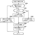
図38に示すステップS153の図柄停止待ち処理は、表示制御プロセスフラグの値が「3」のときに実行される処理である。この処理において、CPU112は、図52に示すように、まず、主基板11から特別図柄確定コマンドを受信したか否かを判別し(ステップS461)、受信していないときには(ステップS461;No)、さらに監視タイマがタイムアウトしたか否かを判別する(ステップS462)。監視タイマがタイムアウトしていないときには(ステップS462;No)、そのまま図柄停止待ち処理を終了する。一方、特別図柄確定コマンドを受信することなく監視タイマがタイムアウトしたときには、何らかの異常が発生したと判断して、可変表示装置4上に所定のエラー画面を表示する制御を行う(ステップS463)。また、監視タイマがタイムアウトする前に特別図柄確定コマンドを受信したときには、可変表示装置4における特別図柄の可変表示を終了させ、各図柄における確定図柄を停止表示する制御を行う(ステップS464)。そして、導出された表示結果が大当りであるか否かを判別し(ステップS465)、大当りであるときには(ステップS465;Yes)、表示制御プロセスフラグの値を大当り表示処理に対応した値である「4」に更新する(ステップS466)。これに対して、表示結果がハズレであるときには(ステップS465;No)、フラグメモリ133に設けられた連続予告フラグがオンとなっているか否かを判別する(ステップS467)。ここで、連続予告の最終回以外となる予告演出が行われる特図ゲームでは、表示結果がリーチ表示態様となることなくハズレとなる。また、連続予告の最後となる予告演出が行われる特図ゲームを開始するときには、図40に示すステップS427にて連続予告フラグがクリアされてオフ状態となっている。従って、連続予告の最終回以外となる予告演出が行われる特図ゲームを開始するときには、ステップS467にて連続予告フラグがオンとなっていると判別される。
【0195】
ステップS467にて連続予告フラグがオンであると判別したとき(ステップS467;Yes)、CPU112は、今回の特図ゲームで再生表示される動画像の最後となるフレームデータにより画像を連続再生するための表示制御指令を、GCL115に対して送出する(ステップS468)。これにより、図44に示すステップS526にて静止画の描画指令を送出したときと同様に、動画像データに含まれている画像データを用いた静止表示が実現される。すなわち、特別図柄の可変表示が停止して1回の特図ゲームが終了するときには、動画像データを用いた静止画像表示が行われ、動画像の再生表示が一時停止されることとなる。ステップS467にて連続予告フラグがオフであると判別したときには(ステップS467;No)、ステップS468をスキップする。そして、ステップS469において、表示制御プロセスフラグの値を「0」に更新する。
【0196】
ステップS154の大当り表示処理は、表示制御プロセスフラグの値が「4」のときに実行される処理である。この処理において、CPU112は、可変表示装置4を制御することにより、大当り遊技状態に応じた画像を表示する制御を行う。例えば、主基板11から送出された所定の大当りラウンド数指示コマンドに対応したラウンド数を、可変表示装置4上に表示させることにより、遊技者に対して報知可能とする。そして、大当り遊技状態において実行されるラウンド遊技が最終ラウンド(例えば、16回目)になると、表示制御プロセスフラグの値を「0」に更新する。
【0197】
上述したパチンコ遊技機1の動作を、次に、可変表示装置4における表示動作を中心とした具体例に基づいて説明する。
【0198】
パチンコ遊技機1の右下位置に設けられたハンドルを遊技者が操作すると、発射モータにより遊技球が遊技領域に打ち込まれ、遊技領域内を下りてくる。主基板11は、各入賞口スイッチ70の入力の有無を監視している。
【0199】
遊技球が普通可変入賞球装置6に入賞すると、始動球検出器により遊技球の入賞が検出される。遊技制御用マイクロコンピュータ100のCPU103は、各入賞口スイッチ70に含まれる始動球検出スイッチからの検出信号がオン状態となると(図28のステップS100;Yes)、ランダムカウンタ121よりランダムR1の値を抽出し、抽出した乱数値を特図保留メモリ120の空きエントリの先頭に登録する(ステップS101)。
【0200】
CPU103は、特図ゲームが実行されていない場合に、特図保留メモリ120の記憶内容を読み取り、各保留番号に対応付けて格納されているランダムR1の値に基づいて可変表示結果を大当りとするか否かを判定する。また、この大当り判定の判定結果と判定回数に基づいて、複数回の特図ゲームにわたり連続した予告演出を実行するか否かを判別する(図30及び図31に示す大当り・連続予告判定処理)。そして、連続予告を実行すると判定したときには、大当りとするか否かの判定回数に対応する連続予告の実行回数を指定するための連続予告回数指定コマンドB0XX(h)を、主基板11から表示制御基板12に対して送出する。
【0201】
また、可変表示の開始条件が成立した特図ゲームにおける大当りとハズレの判定結果に応じて、左・中・右の可変表示部4a〜4cに導出表示させる特別図柄の確定図柄を決定する(図34及び図35に示す確定図柄設定処理)。こうして決定された特別図柄の確定図柄に対応する左・中・右の図柄指定コマンド(91XX(h)、92XX(h)、93XX(h))が、主基板11から表示制御基板12に対して送出される。
【0202】
さらに、CPU103は、図13(A)〜(C)に示す可変表示パターンテーブル149〜151に格納された複数の可変表示パターンのうちから、今回の特図ゲームで使用するものを選択決定し(図36及び図37に示す可変表示パターン設定処理)、選択決定された可変表示パターンに対応する可変表示開始コマンド(80XX(h))を表示制御基板12に対して送出する。
【0203】
表示制御基板12では、CPU112が主基板11から受けた可変表示開始コマンド、左・中・右の図柄指定コマンド、連続予告回数指定コマンド、及びランダムカウンタ130より抽出したランダムR10の値などに基づいて、今回の特図ゲームで使用する動画像表示制御プロセステーブル、台詞表示制御プロセステーブル、図柄表示制御プロセステーブルを決定し、それぞれ、動画像表示制御プロセステーブルメモリ131a、台詞表示制御プロセステーブルメモリ131b、図柄表示制御プロセステーブルメモリ131cから読み出す(図40に示す表示制御設定処理)。こうして読み出された表示制御プロセステーブルに従って、可変表示装置4による特別図柄の可変表示が開始される。そして、連続予告回数指定コマンドにて指定された連続予告の実行回数に基づいてフラグメモリ133に設けられた連続予告フラグがオンとなっているときには、表示制御プロセステーブルに従って所定の予告演出表示が行われる。
【0204】
図53(A)〜(H)及び図54(A)〜(H)は、予告演出表示の具体的な一例として、可変表示装置4の表示領域に配置された画像表示エリア41にて再生表示される動画像の表示態様を示す説明図である。図53(A)〜(H)及び図54(A)〜(H)に示すそれぞれの動画像は、図17(A)に示すCGROM116の動画像データ格納領域116bに格納された動画像データ#1〜#16のそれぞれに所定の復号化処理を施すことにより再生表示されるものである。また、各動画像データ#1〜#16による動画像を順次に再生することで一連の予告演出表示が可能となる。ここで、動画像データ#1〜#16による動画像を全て再生するために要する時間は、通常B(ハズレ)の可変表示パターンによる特図ゲームを3回実行してから、リーチAの可変表示パターンによる特図ゲームを1回実行するまでの、4回分の特図ゲームにわたる予告演出表示が可能となるように調整されている。
【0205】
図55は、動画像A−1の表示制御プロセステーブルにおける設定内容の具体的な一例を示す説明図である。動画像A−1の表示制御プロセステーブルは、CPU112が図40に示すステップS422にて図23に示す動画像表示手順決定テーブル170を用いることにより、連続予告の実行回数が「4」ないし「3」であり、かつ、連続予告カウンタ135のカウント値が「1」であるときに、特図ゲームで使用するものとして選択決定される。すなわち、動画像A−1の表示制御プロセステーブルは、3回又は4回の特図ゲームにわたり連続して予告演出が行われるときに、1回目の特図ゲームで使用される。
【0206】
動画像A−1の表示制御プロセステーブルでは、1番目の動画像表示プロセスタイマ設定値として左・中・右の可変表示部4a〜4cにおける特別図柄を縮小して可変表示装置4の表示領域における左上部に移動させるまでに要する待ち時間が設定されている。また、そのプロセスタイマ設定値に対応する動画像表示制御データには、動画像を非表示に設定するための制御データが含まれている。2番目の動画像表示プロセスタイマ設定値としては、図44のステップS531にて繰り返し呼び出されるフェードイン処理によるフェードイン表示が完了するまでに要する時間が設定されている。また、そのプロセスタイマ値に対応する動画像表示制御データには、フェードイン制御フラグをオン状態にセットするとともに、動画再生を開始するときに使用される1フレーム分のフレームデータの読出位置を指定するための制御データと、そのフレームデータによる静止画像を描画するための制御データとが含まれている。さらに、3番目、4番目、5番目、6番目の動画像表示プロセスタイマ設定値及び動画像表示制御データにより、それぞれ動画像データ#1、#2、#3、#4に基づく動画再生に必要な再生時間や、各々の動画像データの読出位置などが指定され、各動画像データによる動画再生が可能となるように設定されている。
【0207】
図56は、動画像A−2の表示制御プロセステーブルにおける設定内容の具体的な一例を示す説明図である。動画像A−2の表示制御プロセステーブルは、CPU112が動画像表示手順決定テーブル170を用いることにより、連続予告の実行回数が「2」であり、かつ、連続予告カウンタ135のカウント値が「1」であるときに、特図ゲームで使用するものとして選択される。すなわち、動画像A−2の表示制御プロセステーブルは、2回の特図ゲームにわたり連続して予告演出が行われるときに、1回目の特図ゲームで使用される。動画像A−2の表示制御プロセステーブルでは、3番目、4番目、5番目、6番目の動画像表示プロセスタイマ設定値及び動画像表示制御データにより、それぞれ動画像データ#2、#4、#6、#7に基づく動画再生に必要な再生時間や、各々の動画像データの読出位置などが指定され、各動画像データによる動画再生が可能となるように設定されている。
【0208】
図57は、動画像B−1の表示制御プロセステーブルにおける設定内容の具体的な一例を示す説明図である。動画像B−1の表示制御プロセステーブルは、CPU112が動画像表示手順決定テーブル170を用いることにより、連続予告の実行回数が「3」又は「4」であり、かつ、連続予告カウンタ135のカウント値が「2」であるときに、特図ゲームで使用するものとして選択される。すなわち、動画像B−1の表示制御プロセステーブルは、3回又は4回の特図ゲームにわたり連続して予告演出が行われるときに、2回目の特図ゲームで使用される。動画像B−1の表示制御プロセステーブルでは、1番目、2番目、3番目の動画像表示プロセスタイマ設定値及び動画像表示制御データにより、それぞれ動画像データ#5、#6、#7に基づく動画再生に必要な再生時間や、各々の動画像データの読出位置などが指定され、各動画像データによる動画再生が可能となるように設定されている。また、4番目の動画像表示プロセスタイマ設定値により静止描画時間が指定されるとともに、そのプロセスタイマ値に対応する動画像表示制御データにより動画像データ#7に基づく動画像の再生終了時におけるフレームデータを用いた静止描画を行うための設定がなされている。さらに、5番目の動画像表示プロセスタイマ設定値により動画像データ#8に基づく動画再生に必要な再生時間が指定されるとともに、そのプロセスタイマ値に対応する動画像表示制御データにより動画像データ#8の読出位置とともに動画再生を開始するための設定がなされている。
【0209】
図58は、動画像B−2の表示制御プロセステーブルにおける設定内容の具体的な一例を示す説明図である。動画像B−2の表示制御プロセステーブルは、CPU112が動画像表示手順決定テーブル170を用いることにより、連続予告の実行回数が「2」であり、かつ、連続予告カウンタ135のカウント値が「2」であるときに、特図ゲームで使用するものとして選択される。すなわち、動画像B−2の表示制御プロセステーブルは、2回の特図ゲームにわたる連続予告の最後となる予告演出が行われる特図ゲームで使用される。動画像B−2の表示制御プロセステーブルでは、1番目、2番目、3番目、4番目の動画像表示プロセスタイマ設定値及び動画像表示制御データにより、それぞれ動画像データ#8、#9、#11、#12に基づく動画再生に必要な再生時間や、各々の動画像データの読出位置などが指定され、各動画像データによる動画再生が可能となるように設定されている。また、5番目の動画像表示プロセスタイマ設定値により図44のステップS533にて繰り返し呼び出されるフェードイン処理に基づくフェードイン表示が完了するまでに要する時間が設定されているとともに、そのプロセスタイマ値に対応する動画像表示制御データにより動画像データ#12に基づく動画像の再生終了時におけるフレームデータを用いたフェードアウト表示を行うための設定がなされている。さらに、6番目の動画像表示プロセスタイマ設定値により特図ゲームにおける特別図柄の可変表示が終了するまでの待ち時間が設定されているとともに、そのプロセスタイマ値に対応する動画像表示制御データにより動画像を非表示とするための設定がなされている。
【0210】
図59は、動画像Dの表示制御プロセステーブルにおける設定内容の具体的な一例を示す説明図である。動画像Dの表示制御プロセステーブルは、CPU112が動画像表示手順決定テーブル170を用いることにより、連続予告の実行回数が「4」であり、かつ、連続予告カウンタ135のカウント値が「4」であるときに、特図ゲームで使用するものとして選択される。すなわち、動画像Dの表示制御プロセステーブルは、4回の特図ゲームにわたる連続予告の最後となる予告演出が行われる特図ゲームで使用される。動画像B−2の表示制御プロセステーブルでは、1番目、2番目、3番目、4番目の動画像表示プロセスタイマ設定値及び動画像表示制御データにより、それぞれ動画像データ#13、#14、#15、#16に基づく動画再生に必要な再生時間や、各々の動画像データの読出位置などが指定され、各動画像データによる動画再生が可能となるように設定されている。また、5番目の動画像表示プロセスタイマ設定値により図44のステップS533にて繰り返し呼び出されるフェードイン処理に基づくフェードイン表示が完了するまでに要する時間が設定されているとともに、そのプロセスタイマ値に対応する動画像表示制御データにより動画像データ#12に基づく動画像の再生終了時におけるフレームデータを用いたフェードアウト表示を行うための設定がなされている。さらに、6番目の動画像表示プロセスタイマ設定値により特図ゲームにおける特別図柄の可変表示が終了するまでの待ち時間が設定されているとともに、そのプロセスタイマ値に対応する動画像表示制御データにより動画像を非表示とするための設定がなされている。
【0211】
また、図60(A)〜(C)は、それぞれ、台詞A−1、台詞B−1、台詞C−1の表示制御プロセステーブルについて、具体的な構成例を示す図である。これらの台詞表示制御テーブルは、連続予告の実行回数が「4」であるときに、図41に示すステップS502にて、連続予告カウンタ135のカウント値に基づき、図24に示す連続予告中台詞決定テーブル171を用いて選択決定される。すなわち、台詞A−1、台詞B−1、台詞C−1の各表示制御プロセステーブルは、4回の特図ゲームにわたり連続して予告演出が行われるときに、予告演出を行う1回目〜3回目の特図ゲームで使用され、各回の特図ゲームで画像表示エリア41に再生表示される動画像と連動して、台詞表示エリア42に文字列画像を更新表示させる。
【0212】
図61(A)は、図柄表示制御プロセステーブルに従った特別図柄の表示プロセス(可変表示の状態)を示す説明図である。また、図61(B)は、動画像表示制御プロセステーブルに従った動画像の表示プロセス(動画像表示の状態)を示す説明図である。図62は、4回の特図ゲームにわたり連続して予告演出を行う場合の表示制御例を示すタイミング図である。4回の特図ゲームにわたり連続して予告演出を行うときには、図23に示す動画像表示手順決定テーブル170に基づいて、1回目、2回目、3回目、4回目の特図ゲームのそれぞれにおいて、動画像A−1、動画像B−1、動画像C−1、動画像Dの表示制御プロセステーブルが使用される。CPU112は、各回の特図ゲームにおいて、使用する動画像表示制御プロセステーブルでの設定に応じてCGROM116の動画像データ格納領域116bにおける動画像データの読出位置を決定し、GCL115に対して動画像の再生を指示する表示制御指令を送出する。
【0213】
GCL115は、CPU112から動画像の再生を指示する表示制御指令を受けると、動画像データ格納領域116bから動画像データを読み出して動画再生を行うことで、可変表示装置4の表示領域に配置された画像表示エリア41に、図63(A)から図64(H)まで続く一連の動画像を再生表示させる。すなわち、図62に示すように、連続予告の1回目となる予告演出を行う特図ゲームにおいて特別図柄の可変表示を開始すると、まず、プロセスcに従って左・中・右の特別図柄を縮小して可変表示装置4の表示領域左上部に移動させるための演出表示を行い、プロセスaに従って左・中・右図柄が可変表示される。このとき、動画像については、特別図柄の縮小演出が行われている間はプロセスeに従って非表示状態とされ、特別図柄の縮小が完了すると、動画再生を開始するときに使用するフレームデータの画像を用いて、プロセスfに従ったフェードイン表示を実行する。このとき、CPU112は、フェードイン処理(図44に示すステップS531)を実行することにより、動画再生を開始するときに使用されるフェードイン対象画像の透明度が徐々に低下していくフェードイン表示を行って、図63(A)において画像表示エリア41に表示される画像を、図47(A)〜(D)に示すように段階的に出現させる。すなわち、CPU112は、演出に用いられる動画像のうち最初に表示される画像をフェードイン対象画像に設定して、フェードイン処理により段階的に出現させる。
【0214】
フェードイン表示が完了すると、動画像データ#1〜#4に基づく動画像が順次に再生表示されて、1回目の特図ゲームにおける特別図柄の確定図柄が導出表示されるときに、動画像データ#4に基づく動画像の再生終了時におけるフレームデータを用いた一時停止制御が行われる。そして、1回目の特図ゲームにおける可変表示結果が確定表示されているあいだ、画像表示エリア41では、プロセスiに従って動画像の静止表示が行われる。また、このときCPU112は、フェードイン処理(図44に示すステップS531)を実行することにより、一時停止制御を開始するときに表示される画像の透明度が徐々に低下していくフェードイン表示を行うようにしてもよい。あるいは、CPU112は、フェードアウト処理(図44に示すステップS533)を実行することにより、演出に用いられる動画像のうち一時停止制御の直前で最後に表示される画像をフェードアウト対象画像に設定して、その画像の透明度が徐々に高められるフェードアウト表示を行うようにしてもよい。フェードアウト表示を行う場合には、図63(D)において画像表示エリア41に表示されている画像をフェードアウト対象画像に設定すればよい。
【0215】
続いて、2回目の特図ゲームにおける可変表示が開始されると、画像表示エリア41では、動画像データ#4に基づく動画像から再び再生表示が開始される。このとき、CPU112は、2回目の特図ゲームにおける演出に用いられる動画像のうち一時停止制御の終了直後に最初に表示される画像をフェードイン対象画像に設定して、フェードイン処理(ステップS531)を実行することにより、図63(E)において画像表示エリア41に表示される画像を段階的に出現させるようにしてもよい。あるいは、CPU112は、一時停止制御の際に表示していた画像をフェードアウト対象画像に設定してフェードアウト処理(ステップS533)を実行することにより、フェードアウト対象画像を段階的に消失させると共に、図63(E)において画像表示エリア41に表示される画像を段階的に出現させるようにしてもよい。そして、動画像データ#4〜#7に基づく動画像が順次に再生表示された後、プロセスiに従って動画像データ#7に基づく動画像の再生終了時におけるフレームデータを用いた動画像の静止表示が行われる。この後、動画像表示プロセスタイマがタイムアウトしたときに、動画像データ#8に基づく動画像の再生表示が開始されることとなる。こうして2回目の特図ゲームにおける特別図柄の確定図柄が導出表示されるときには、動画像データ#8に基づく動画像の再生終了時におけるフレームデータを用いた一時停止制御が行われる。そして、2回目の特図ゲームにおける可変表示結果が確定表示されているあいだ、画像表示エリア41では、プロセスiに従って動画像の静止表示が行われる。
【0216】
3回目の特図ゲームにおける可変表示が開始されると、画像表示エリア41では、動画像データ#8に基づく動画像から再び再生表示が開始され、動画像データ#9、#10に基づく動画像が順次に再生表示される。動画像データ#10に基づく動画像の再生表示が終了したときには、動画像C−1の表示制御プロセステーブルにおける設定に基づき、プロセスiに従って動画像データ#10に基づく動画像の再生終了時におけるフレームデータを用いた動画像の静止表示が行われる。この後、動画像表示プロセスタイマがタイムアウトすると、動画像データ#11、#12に基づく動画動が順次に再生表示されることとなる。こうして3回目の特図ゲームにおける特別図柄の確定図柄が導出表示されるときには、動画像データ#12に基づく動画像の再生終了時におけるフレームデータを用いた一時停止制御が行われる。そして、3回目の特図ゲームにおける可変表示結果が確定表示されているあいだ、画像表示エリア41では、プロセスiに従って動画像の静止表示が行われる。
【0217】
4回目の特図ゲームにおける可変表示が開始されると、画像表示エリア41では、動画像データ#13〜#16に基づく動画像が順次に再生表示される。そして、動画像データ#16に基づく動画像の再生表示が終了すると、プロセスgに従ったフェードアウト表示を実行する。このとき、CPU112は、フェードアウト処理(図44に示すステップS533)を実行することにより、動画再生の終了時における画像(フェードアウト対象画像)の透明度が徐々に高められるフェードアウト表示を行って、図63(H)における画像表示エリア41に表示されている画像を、図49(A)〜(D)に示すように段階的に消失させる。すなわち、CPU112は、演出に用いられる動画像のうち最後に表示される画像をフェードアウト対象画像に設定して、フェードアウト処理により段階的に消失させる。この後、可変表示中の特別図柄がプロセスdに従って拡大されて可変表示装置4の中央部に移動させるための演出表示が行われ、リーチAの可変表示パターンに対応した総可変表示時間が経過すると、連続予告が行われた後の可変表示結果として、特別図柄の確定図柄が導出表示される。
【0218】
このように、4回の特図ゲームにわたる連続予告では、図17(A)に示すCGROM116の動画像データ格納領域116bに格納された動画像データ#1〜#16に基づく全ての動画像が順次に再生されて、画像表示エリア41に表示される。また、動画像の再生時間は、4回の特図ゲームにわたる連続予告に適合したものに調整されることとなる。さらに、各特図ゲームにて可変表示が終了して表示結果が確定表示されるときには、CPU112が図52に示すステップS468にて、フレームデータにより画像を連続再生するための表示制御指令をGCL115に対して送出する。これにより、特図ゲームにおける可変表示結果が表示されているあいだは、画像表示エリア41における動画像の再生表示が一時停止されることとなる。一時停止された動画像の再生表示は、次に行われる特図ゲームの開始時に、CPU112が図40に示すステップS425の処理を実行することにより、一時停止を解除して再び開始することができる。
【0219】
また、CPU112は、図24に示す連続予告中台詞決定テーブル171を用いることで、1回目、2回目、3回目の特図ゲームのそれぞれにおいて、台詞A−1、台詞B−1、台詞C−1の表示制御テーブルを選択決定する。そして、選択決定された各台詞表示制御テーブルに基づき、CGROM116の台詞画像データ格納領域116cにおける文字列画像データの読出位置を決定し、GCL115に対して文字列画像の生成を指示する表示制御指令を送出する。
【0220】
GCL115は、各回の特図ゲームにおいてCPU112から文字列画像の生成を指示する表示制御指令を受けるごとに、台詞画像データ格納領域116cから文字列画像データを読み出して順次に文字列画像を生成し、可変表示装置4の表示領域に配置された台詞表示エリア42に、図63(A)から図64(H)までに示すような文字列画像を順次に表示する。ここで、台詞画像データ格納領域116cに格納された文字列画像データには、文字列画像の一部を他の部分とは異なる表示態様で表示させるための表示制御データも含まれている。これにより、例えば図63(B)に示すように、台詞表示エリア42に表示された文字列画像の一部が橙色表示されるなど、通常とは異なる表示態様で台詞を表示することもできる。このようにして、GCL115が順次に生成した文字列画像を台詞表示エリア42に順次に表示させることにより、台詞としての文字列画像が、動画像の再生表示と連動して更新表示されることとなる。
【0221】
ここで、4回目の特図ゲームでは、表示結果をハズレとするか大当りとするかに応じて、図25(A)に示すハズレ最終予告時台詞決定テーブル172あるいは図25(B)に示す大当り最終予告時台詞決定テーブル173を用いることにより、台詞D−1、台詞D−2、台詞D−3、台詞D−4の表示制御プロセステーブルのうちのいずれかが選択決定される。
【0222】
図65(A)〜(D)は、ハズレ最終予告時台詞決定テーブル172又は大当り最終予告時台詞決定テーブル173を用いて選択される台詞D−1〜台詞D−4の表示制御プロセステーブルについて、その具体的な構成例を示す図である。図66〜図69は、それぞれ台詞D−1〜台詞D−4の表示制御プロセステーブルに従って作成される文字列画像の可変表示装置4における表示状態を示す図である。なお、図64(E)〜(H)で示した文字列画像の表示状態は、図69(A)〜(D)に示すものと同一である。すなわち、図64(E)〜(H)に示す文字列画像は、台詞D−4の表示制御プロセステーブルに従って表示されたものである。
【0223】
この例では、台詞D−1〜台詞D−4の各表示制御プロセステーブルに従って台詞表示エリア42に最初に表示される文字列画像が、いずれも文字列画像データ#4−1の画像であるものとする。従って、図66(A)、図67(A)、図68(A)、図69(A)に示すように、台詞D−1〜台詞D−4のいずれの表示制御プロセステーブルを用いた場合でも、台詞表示エリア42に最初に表示される文字列画像は同一となり、この時点では、いずれの表示制御プロセステーブルを用いた台詞表示が行われるかを認識することが困難である。
【0224】
また、台詞D−1〜台詞D−4の各表示制御プロセステーブルを用いたときには、文字列画像データ#4−1の文字列画像の次に、いずれも文字列画像データ#4−2の文字列画像が台詞表示エリア42に表示される。従って、図66(B)、図67(B)、図68(B)、図69(B)に示すように、台詞D−1〜台詞D−4のいずれの表示制御プロセステーブルを用いた場合でも、台詞表示エリア42に2番目に表示される文字列画像も同一となり、この時点でも、いずれの表示制御プロセステーブルを用いた台詞表示が行われるかを認識することが困難である。
【0225】
続いて、台詞D−1の表示制御プロセステーブルを用いた場合には、文字列画像データ#4−3、文字列画像データ#4−7が、台詞画像データ格納領域116cから順次に読み出されて、各データに対応する文字列画像が順次生成される。そして、台詞表示エリア42には、図66(C)及び図66(D)に示すように、台詞となる文字列画像が順次に表示されることとなる。ここで、図42に示すように、台詞D−1の表示制御プロセステーブルを用いた台詞が表示されたときの大当り信頼度は、台詞D−1〜台詞D−4のうちで最も低いものとなる。
【0226】
また、台詞D−2の表示制御プロセステーブルを用いた場合には、文字列画像データ#4−4、文字列画像データ#4−8が、台詞画像データ格納領域116cから順次に読み出されて、各データに対応する文字列画像が順次生成される。そして、台詞表示エリア42には、図67(C)及び図67(D)に示すように、台詞となる文字列画像が順次に表示されることとなる。ここで、台詞D−2の表示制御プロセステーブルを用いた台詞が表示されたときの大当り信頼度は、台詞D−1よりも高いものの、台詞D−3及び台詞D−4よりは低いものとなっている。
【0227】
台詞D−3の表示制御プロセステーブルを用いた場合には、文字列画像データ#4−5、文字列画像データ#4−9が、台詞画像データ格納領域116cから順次に読み出されて、各データに対応する文字列画像が順次生成される。そして、台詞表示エリア42には、図68(C)及び図68(D)に示すように、台詞となる文字列画像が順次に表示されることとなる。ここで、台詞D−3の表示制御プロセステーブルを用いた台詞が表示されたときの大当り信頼度は、台詞D−1及び台詞D−2よりも高く、台詞D−4よりは低いものとなっている。ここで、図68(D)に示す文字列画像では、「大当り」を示す文字列が赤色表示されるなど、一部の文字列が他の部分とは異なる表示態様となっている。こうした設定は、文字列画像データ#4−9に含まれる表示制御データなどで指定されている。GCL115は、文字列画像データ#4−9に従った文字列画像を生成することにより、図68(D)に示すような文字列画像を台詞表示エリア42に表示させることができる。図68(D)に示す文字列画像の表示により、通常の表示態様である図66(D)や図67(D)などに示す文字列画像が表示されたときよりも大当りとなる可能性が高いことを、遊技者等が容易に認識することができる。
【0228】
台詞D−4の表示制御プロセステーブルを用いた場合には、文字列画像データ#4−6、文字列画像データ#4−10が、台詞画像データ格納領域116cから順次に読み出されて、各データに対応する文字列画像が順次生成される。そして、台詞表示エリア42には、図69(C)及び図69(D)に示すように、台詞となる文字列画像が順次に表示されることとなる。ここで、台詞D−4の表示制御プロセステーブルを用いた台詞が表示されたときには、必ず可変表示結果が大当りとなる。このため、台詞表示エリア42には、図69(D)に示すように、可変表示結果が大当りとなることを示す文字列画像が表示される。この文字列画像では、「大当り」を示す文字列が赤色表示されるなど、一部の文字列が他の部分とは異なる表示態様となっている。従って、図69(D)に示す文字列画像が表示されたときには、可変表示結果が必ず大当りとなることを認識することが可能である。
【0229】
このように台詞表示エリア42にて更新表示が行われた後、最終的に表示された文字列画像の種類に応じて、特図ゲームの表示結果が大当りとなる確率は異なるものとなる。すなわち、ハズレ最終予告時台詞決定テーブル172及び大当り最終予告時台詞決定テーブル173では、台詞表示エリア42における更新表示後の文字列画像の種類に応じて大当りとなる確率が異なるように、決定用データとしてのランダムR10の値が各台詞表示制御プロセステーブルに対して割り振られている。また、ハズレ最終予告時台詞決定テーブル172及び大当り最終予告時台詞決定テーブル173では、文字列画像の表示態様に応じて大当りとなる確率が異なるように、ランダムR10の値が各台詞表示制御プロセステーブルに対して割り振られている。
【0230】
図70は、2回の特図ゲームにわたり連続して予告演出を行う場合の表示制御例を示すタイミング図である。2回の特図ゲームにわたり連続して予告演出を行うときには、図23に示す動画像表示手順決定テーブル170に基づいて、1回目、2回目の特図ゲームのそれぞれにおいて、動画像A−2、動画像B−2の表示制御プロセステーブルが使用される。CPU112は、各回の特図ゲームにおいて、使用する動画像表示制御プロセステーブルでの設定に応じてCGROM116の動画像データ格納領域116bにおける動画像データの読出位置を決定し、GCL115に対して動画像の再生を指示する表示制御指令を送出する。
【0231】
GCL115は、CPU112から動画像の再生を指示する表示制御指令を受けると、動画像データ格納領域116bから動画像データを読み出して動画再生を行うことで、可変表示装置4の表示領域に配置された画像表示エリア41に、図71(A)から図71(H)まで続く一連の動画像を再生表示させる。このときに表示される動画像は、図70に示すように、動画像データ#2、#4、#6、#7〜#9、#11、#12に基づいて順次に生成される画像であり、動画像データ格納領域116bに格納されている動画像データの一部に基づく動画像である。すなわち、CPU112は、各特図ゲームにおける可変表示を開始するときに、図40に示すステップS422にて動画像表示手順決定テーブル170を用いて動画像表示制御プロセステーブルを選択決定することにより、連続予告の実行回数に応じて動画再生による動画像の再生位置を決定することができる。
【0232】
また、CPU112は、図24に示す連続予告中台詞決定テーブル171を用いることで、1回目の特図ゲームにおいて、台詞A−3の表示制御プロセステーブルを選択決定する。そして、GCL115に対して文字列画像の生成を指示する表示制御指令を送出する。GCL115は、CPU112から文字列画像の生成を指示する表示制御指令を受けるごとに、台詞画像データ格納領域116cから文字列画像データを読み出して順次に文字列画像を生成し、台詞表示エリア42に、図71(A)〜(H)に示すような文字列画像を順次に表示する。このとき台詞画像データ格納領域116cから読み出される文字列画像データにも、文字列画像の一部を他の部分とは異なる表示態様で表示させるための表示制御データが含まれていることがある。これにより、例えば図71(A)に示すように、台詞表示エリア42に表示された文字列画像の一部が青色表示されるなど、通常とは異なる表示態様で台詞を表示することもできる。
【0233】
こうした複数回の特図ゲームにわたり連続した予告演出表示が行われた後、可変表示パターンに対応した総可変表示時間が経過したときに、表示結果となる特別図柄の確定図柄が導出表示される。このとき導出表示された確定図柄がハズレとなる組合せであれば、特別可変入賞球装置7の開閉板の開成等を行わず、1回分の特図ゲームの実行が終了する。一方、確定図柄が大当り組合せとなっていれば、パチンコ遊技機1は大当り遊技状態となり、特別可変入賞球装置7の開閉板が一定時間又は一定数の遊技球が入賞するまで開成し、開閉を一定サイクル繰り返すこととなる。
【0234】
以上説明したように、この実施の形態では、複数回の特図ゲームにわたり連続した予告演出を行うときに、CPU112が連続予告の実行回数や連続予告カウンタ135のカウント値に基づき、図23に示す動画像表示手順決定テーブル170を用いて今回の特図ゲームで使用する動画像表示制御プロセステーブルを選択決定する。各動画像表示制御プロセステーブルには、動画像の再生時間を設定するための動画像表示プロセスタイマ設定値や、CGROM116の動画像データ格納領域116bにおける動画像データの読出位置などを示す動画像表示制御データが設定されている。従って、CPU112は、選択決定した動画像表示制御プロセステーブルでの設定に応じた表示制御指令をGCL115に対して送出することにより、連続予告が実行される特図ゲームの実行回数に応じて、動画再生による動画像の再生位置を決定することができる。これにより、連続した動画像を用いた演出表示が行われる特図ゲームの実行回数が異なる場合でも、同一の動画像データを用いて動画像により演出表示を行うことができる。同一の動画像データを用いることで、動画像データのデータ量を増大させることなく多様な演出表示を可能として動画像データの格納に必要な記憶容量を抑えることができ、データ圧縮された動画像データを用いた演出表示のための制御負担を軽減することができる。
【0235】
また、CPU112は、連続予告の最終回以外となる予告演出が行われる特図ゲームにおける可変表示が終了するときに、図52に示すステップS468の処理を実行することで、GCL115による動画再生を一時停止する。そして、次の特図ゲームにおける可変表示の開始条件が成立したときに、図40に示すステップS425の処理を実行することで、動画再生の一時停止を解除する。これにより、複数回の特図ゲームにわたり連続した動画像を用いた演出表示を行うときに、可変表示の開始タイミングにズレが生じた場合などでも、動画像の再生タイミングを調整することができるので、遊技者の演出表示に対する違和感が生じることを防止できる。
【0236】
CPU103は、図30のフローチャートに示す大当り・連続予告判定処理において、ステップS303の大当り判定処理を実行することにより、特図ゲームの開始条件が成立したときに、特図保留メモリ120によって保留されている特図ゲームの可変表示結果が大当りとなるか否かを判定することができる。また、ステップS309又はS311にて連続予告回数メモリ126に変数kに基づく値をセットすることにより、連続予告を実行する回数を決定することができる。そして、ステップS314では、ステップS310にて設定された大当り時連続予告判定テーブル143又はステップS312にて設定されたハズレ時連続予告判定テーブル142を用いて、大当りの判定結果と判定回数に基づいて連続予告を実行するか否かを判定することができる。そして、ハズレ時連続予告判定テーブル142及び大当り時連続予告判定テーブル143では、予告演出が連続して行われる特図ゲームの実行回数が増加するに従って表示結果が大当りとなる確率が高くなるように、決定用データとしてのランダムR6の値が割り振られている。これにより、特図ゲームの表示結果が大当たりとなる確率は、動画像を用いた演出表示が連続して実行されるに従って高まってゆくので、遊技者の期待感を高めることができる。
【0237】
図52に示すステップS468の処理を実行することで動画再生を一時停止した後に、次の特図ゲームにおける可変表示の開始条件が成立するまでの間は、画像表示エリア41にて、フレームデータの連続再生による動画像の静止表示が行われる。これにより、動画再生のときと同一のデータを用いて静止画像を表示させることができるので、データ量が増大することを防止でき、データの格納に必要な記憶容量を抑えることができる。
【0238】
また、同一の動画像データを用いた動画再生が行われるときでも、可変表示装置4の表示画面に配置された台詞表示エリア42に表示される文字列画像の種類に応じて、特図ゲームの表示結果が大当りとなる確率を異ならせることができる。これにより、動画像データのデータ量を増大させることなく多様な演出表示が可能となる。また、動画像データの格納に必要な記憶容量を抑えることができるので、データ圧縮された動画像データを用いた演出表示のための制御負担を軽減することができる。
【0239】
さらに、台詞表示エリア42における更新表示後に表示された文字列画像の種類に応じて特図ゲームの表示結果が大当りとなる確率が異なるものとなるので、さらに長い期間にわたり遊技者の大当りに対する期待感を持続させることができる。
【0240】
また、動画像データに含まれている1フレーム分の画像データを用いてフェードイン処理やフェードアウト処理を行うことができるので、動画像データのデータ量が増大することなく、多様な演出表示が可能となる。さらに、動画像データに含まれている画像データを用いた静止表示を行うことで、静止表示を実現するために必要な動画像データを削減することができ、動画像データ全体のデータ量を低減させることができる。加えて、演出に用いられる動画像の静止表示を行うときに、動画像の一時停止制御が行われる間に表示される画像を段階的に出現させるフェードイン表示や、演出に用いられる動画像のうち一時停止制御の直前で最後に表示される画像を段階的に消失させるフェードアウト表示を行うこともできる。また、動画像の静止表示を解除するときには、演出に用いられる動画像のうち一時停止制御の終了直後に最初に表示される画像を段階的に出現させるフェードイン表示や、一時停止制御が行われる間に表示されていた画像を段階的に消失させるフェードアウト表示を行うこともできる。これにより、画像データのデータ量を増大させることなく多様な演出表示を可能として画像データの格納に必要な記憶容量を抑えることができ、データ圧縮された画像データを用いた演出表示のための制御負担を軽減することができる。また、画像切替時の違和感を緩和することもできる。
【0241】
この発明は、上記実施の形態に限定されず、種々の変形及び応用が可能である。例えば、上記実施の形態では、台詞表示制御プロセステーブルを用いた場合には、台詞表示エリア42にて複数種類の文字列画像が順次表示されて台詞の更新表示が行われるものとして説明した。しかしながら、この発明はこれに限定されるものではなく、台詞表示エリア42にて単一の文字列画像を表示させるための台詞表示制御テーブルを含んでいてもよい。
【0242】
また、上記実施の形態では、動画像の再生表示と連動して台詞を表示するための文字列画像が表示されるものとして説明したが、これに限定されるものではなく、例えば、動画像として再生表示された場面(場所や地名、時代、時期、時刻など)を説明するための文字列画像や、動画像として再生表示されたもの(名前や出生地、年齢、原産地、大きさ、各種の能力値等)を説明するための文字列画像など、任意の文字列画像を用いたものであればよい。
【0243】
上記実施の形態では、可変表示装置4の表示画面に3つの可変表示部4a〜4cが配置され、左・中・右の特別図柄がそれぞれ可変表示されるものとして説明した。しかしながら、この発明はこれに限定されるものではなく、可変表示装置4に設けられた複数の可変表示領域において、各々が識別可能な複数種類の識別情報を可変表示するものであればよい。例えば、可変表示装置4の表示画面に1つの特別図柄表示エリアと3つの可変表示領域を含む飾り図柄表示エリアとを配置し、特別図柄表示エリアにて特別図柄が可変表示されるとともに、3つの可変表示領域において左・中・右の飾り図柄がそれぞれ可変表示されるものであってもよい。
【0244】
また、上記実施の形態では、動画像の再生表示と連動して台詞を表示するための文字列画像が表示されるものとして説明したが、これに限定されるものではなく、例えば、動画像として再生表示された場面(場所や地名、時代、時期、時刻等)を説明するための文字列画像や、動画像として再生表示されたもの(名前や出生地、年齢、原産地、大きさ、各種の能力値等)を説明するための文字列画像など、任意の文字列画像を用いたものであればよい。
【0245】
図1及び図4に示した装置構成、図5、図7、図14〜図16、図19及び図21に示すブロック構成、図9〜図13、図22〜図25、図55〜図60及び図64に示すテーブル構成、図26〜図32、図34〜図41、図43〜図45、図48及び図50〜図52に示すフローチャート構成や、図47、図49、図53、図54、図63、図64、図66〜図69、図71等の表示例は、発明の趣旨を逸脱しない範囲で任意に変更及び修正が可能である。
【0246】
さらに、パチンコ遊技機1の動作をシミュレーションするゲーム機などにも本発明を適用することができる。本発明を実現するためのプログラム及びデータは、コンピュータ装置等に対して、着脱自在の記録媒体により配布・提供される形態に限定されるものではなく、予めコンピュータ装置等の有する記憶装置にプリインストールしておくことで配布される形態を採っても構わない。さらに、本発明を実現するためのプログラム及びデータは、通信処理部を設けておくことにより、通信回線等を介して接続されたネットワーク上の、他の機器からダウンロードすることによって配布する形態を採っても構わない。
【0247】
そして、ゲームの実行形態も、着脱自在の記録媒体を装着することにより実行するものだけではなく、通信回線等を介してダウンロードしたプログラム及びデータを、内部メモリ等にいったん格納することにより実行可能とする形態、通信回線等を介して接続されたネットワーク上における、他の機器側のハードウェア資源を用いて直接実行する形態としてもよい。さらには、他のコンピュータ装置等とネットワークを介してデータの交換を行うことによりゲームを実行するような形態とすることもできる。
【0248】
また、本発明は、入賞球の検出に応答して所定数の賞球を払い出す払出式遊技機に限定されるものではなく、遊技球を封入し入賞球の検出に応答して得点を付与する封入式遊技機にも適用することができる。
【0249】
【発明の効果】
以上説明したように本発明は、以下に示す効果を有する。
【0250】
本発明の遊技機によれば、再生期間決定手段が、連続回数決定手段により連続した動画像を用いた演出表示を行うことが決定された識別情報の可変表示回数に応じて、データ再生手段が行う動画再生による動画像の再生期間を決定するので、連続した動画像を用いた演出表示が行われる可変表示の実行回数が異なる場合でも、同一の動画像データを用いて動画像による演出表示を行うことができる。これにより、動画像データのデータ量を増大させることなく多様な演出表示を可能として動画像データの格納に必要な記憶容量を抑えることができ、データ圧縮された動画像データを用いた演出表示のための制御負担を軽減することができる。また、識別情報の可変表示が終了するときに、動画再生停止手段がデータ再生手段による動画再生を一時停止して、その後に可変表示の開始条件が成立したことに基づいて、動画像表示再開手段が可変表示装置における動画像表示の一時停止を解除するので、複数回の識別情報の可変表示にわたり連続した動画像を用いた演出表示を行うときに、可変表示の開始タイミングにズレが生じた場合でも、遊技者の演出表示に対する違和感が生じることを防止できる。また、識別情報の可変表示を実行しているときに、データ再生手段が行う動画再生による動画像と文字列画像生成手段により生成された文字列画像とを組み合わせた演出表示を、文字列表示制御手段が可変表示装置に行わせる。ここで、文字列表示制御手段が可変表示装置に表示させる文字列画像の種類に応じて特定表示結果となる確率を異ならせるように決定用データが各文字列画像表示パターンに割り振られている文字列決定用テーブルを用いて、パターン決定手段が文字列画像表示パターンを選択決定するので、同一の動画像データを用いた動画再生が行われるときでも、可変表示装置に表示される文字列画像の種類に応じて特定表示結果となる確率を異ならせることができる。これにより、動画像データのデータ量を増大させることなく多様な演出表示を可能として動画像データの格納に必要な記憶容量を抑えることができ、データ圧縮された動画像データを用いた演出表示のための制御負担を軽減することができる。また、文字列画像生成手段によって生成される文字列画像の表示態様に応じて特定表示結果となる確率を異ならせることができるので、遊技者が特定遊技状態となる可能性を容易に認識することができ、特定遊技状態に対する期待感が高められる。
【0251】
また、連続予告判定手段は、連続回数決定手段により決定される識別情報の可変表示回数が多くなるに従って識別情報の表示結果が特定表示結果となる確率が高くなるように、決定用データが連続予告を実行するか否かの判定結果に対して割り振られている連続予告決定用テーブルを用いて、複数回の識別情報の可変表示にわたる連続予告を実行するか否かを決定するので、識別情報の表示結果が特定表示結果となる確率は、動画像を用いた演出表示が長く継続するに従って高まってゆくこととなる。これにより、遊技者の期待感を高めることができ、遊技の興趣性が向上する。
【0252】
また、動画再生停止手段により動画再生が一時停止された後、可変表示の開始条件が成立するまでの間、静止画表示制御手段がデータ再生手段に動画像のフレームデータを連続再生させることで可変表示装置上に静止画像を表示させるので、動画像を再生するときと同一のデータを用いて静止画像を表示させることができる。これにより、データ量が増大することを防止でき、データの格納に必要な記憶容量を抑えることができる。
【0255】
また、事前判定手段によって特定表示結果とすることが決定されたときに識別情報の表示結果が特定表示結果となることを示す文字列画像を文字列画像生成手段により生成することができる。これにより、遊技者にとって意外な演出表示が可能となり、文字列画像に対する関心を高め、文字列画像を用いた演出表示の効果を高めることができる。
【0256】
また、フェードイン画像生成手段がデータ再生手段による動画再生を開始するときに使用されるフレームデータから透過度を段階的に高めていった複数のフェードイン画像を生成し、フェードイン処理手段がフェードイン画像生成手段により生成された各フェードイン画像を、透過度が最も高められているフェードイン画像から、透過度がより低いフェードイン画像に順次移行させ、最終的にフレームデータの画像を表示させることによりフェードイン処理を実行する。また、フェードアウト画像生成手段がデータ再生手段による動画再生を終了するときに使用されるフレームデータから透過度を段階的に高めていった複数のフェードアウト画像を生成し、フェードアウト処理手段がフェードアウト画像生成手段により生成された各フェードアウト画像を、動画再生の終了時におけるフレームデータの画像から、透過度がより高められているフェードアウト画像に順次移行させ、最終的に透過度が最も高められているフェードアウト画像を表示させることによりフェードアウト処理を実行する。これにより、動画像データのデータ量を増大させることなく、フェードイン表示やフェードアウト表示を行うことができるので、動画像データのデータ量を増大させることなく多様な演出表示を可能として動画像データの格納に必要な記憶容量を抑えることができ、データ圧縮された動画像データを用いた演出表示のための制御負担を軽減することができる。また、画像切替時の違和感を緩和することができる。
【図面の簡単な説明】
【図1】本発明の実施の形態におけるパチンコ遊技機の正面図である。
【図2】可変表示装置における画像表示例を示す図である。
【図3】この実施の形態で用いられる特別図柄の例を示す図である。
【図4】本発明の実施の形態におけるパチンコ遊技機の背面図である。
【図5】主基板における回路構成等を示すブロック図である。
【図6】表示制御コマンドの内容の一例を示す図である。
【図7】遊技制御用マイクロコンピュータの構成例を示すブロック図である。
【図8】遊技制御用マイクロコンピュータのランダムカウンタによりカウントされる各乱数の例を示す図である。
【図9】大当り判定テーブルの構成例を示す図である。
【図10】連続予告判定テーブルの構成例を示す図である。
【図11】大当り図柄決定用テーブルの構成例を示す図である。
【図12】左・中・右の図柄決定用テーブルの構成例を示す図である。
【図13】可変表示パターンテーブルの構成例を示す図である。
【図14】表示制御基板におけるハードウェア構成の一例を示すブロック図である。
【図15】GCLの構成例を示すブロック図である。
【図16】CGROMにおけるデータ格納領域の構成例を示すブロック図である。
【図17】動画像データ格納領域及び台詞画像データ格納領域に格納されるデータの構成例を示すブロック図である。
【図18】動画像データにおけるストリーム構成の一例を示す図である。
【図19】表示制御基板の構成例を示すブロック図である。
【図20】表示制御基板のランダムカウンタによりカウントされる乱数の例を示す図である。
【図21】表示制御プロセステーブルメモリの構成例を示す図である。
【図22】表示制御プロセステーブルの構成例を示す図である。
【図23】動画像表示手順決定テーブルの構成例を示す図である。
【図24】連続予告中台詞決定テーブルの構成例を示す図である。
【図25】最終予告時台詞決定テーブルの構成例を示す図である。
【図26】遊技制御メイン処理を示すフローチャートである。
【図27】遊技制御割込処理を示すフローチャートである。
【図28】特別図柄プロセス処理を示すフローチャートである。
【図29】図28における特別図柄通常処理の詳細を示すフローチャートである。
【図30】図29における大当り・連続予告判定処理の詳細を示すフローチャートである。
【図31】図29における大当り・連続予告判定処理の詳細を示すフローチャートである。
【図32】図30における大当り判定処理の詳細を示すフローチャートである。
【図33】連続予告の実行確率と大当り信頼度の一例を示す説明図である。
【図34】図28における確定図柄設定処理の詳細を示すフローチャートである。
【図35】図28における確定図柄設定処理の詳細を示すフローチャートである。
【図36】図28における可変表示パターン設定処理の詳細を示すフローチャートである。
【図37】図28における可変表示パターン設定処理の詳細を示すフローチャートである。
【図38】表示制御プロセス処理を示すフローチャートである。
【図39】図38における可変表示開始コマンド受信待ち処理の詳細を示すフローチャートである。
【図40】図38における表示制御設定処理の詳細を示すフローチャートである。
【図41】図40における台詞表示手順決定処理の詳細を示すフローチャートである。
【図42】各台詞表示制御プロセステーブルの選択確率と大当り信頼度の一例を示す説明図である。
【図43】図38における可変表示中処理の詳細を示すフローチャートである。
【図44】図43における動画像表示制御処理の詳細を示すフローチャートである。
【図45】図44におけるフェードイン処理の詳細を示すフローチャートである。
【図46】フェードイン処理及びフェードアウト処理に用いられる数式の例を示す説明図である。
【図47】フェードイン処理により作成されるフェードイン画像の表示状態を示す説明図である。
【図48】図44におけるフェードアウト処理の詳細を示すフローチャートである。
【図49】フェードアウト処理により作成されるフェードアウト画像の表示状態を示す説明図である。
【図50】図43における台詞画像表示制御処理の詳細を示すフローチャートである。
【図51】図43における図柄表示制御処理の詳細を示すフローチャートである。
【図52】図38における図柄停止待ち処理の詳細を示すフローチャートである。
【図53】動画像データに基づく動画像の再生表示例を示す図である。
【図54】動画像データに基づく動画像の再生表示例を示す図である。
【図55】動画像A−1表示制御プロセステーブルの具体的な構成の一例を示す図である。
【図56】動画像A−2表示制御プロセステーブルの具体的な構成の一例を示す図である。
【図57】動画像B−1表示制御プロセステーブルの具体的な構成の一例を示す図である。
【図58】動画像B−2表示制御プロセステーブルの具体的な構成の一例を示す図である。
【図59】動画像D表示制御プロセステーブルの具体的な構成の一例を示す図である。
【図60】台詞表示制御プロセステーブルの具体的な構成例を示す図である。
【図61】特別図柄及び動画像の表示プロセスを示す説明図である。
【図62】4回の特図ゲームにわたり連続して動画像を用いた予告演出を行う具体例におけるシーケンス図である。
【図63】予告演出が行われる特図ゲームにおける表示状態の一例を示す図である。
【図64】予告演出が行われる特図ゲームにおける表示状態の一例を示す図である。
【図65】台詞表示制御プロセステーブルの具体的な構成例を示す図である。
【図66】予告演出が行われる特図ゲームにおける表示状態の一例を示す図である。
【図67】予告演出が行われる特図ゲームにおける表示状態の一例を示す図である。
【図68】予告演出が行われる特図ゲームにおける表示状態の一例を示す図である。
【図69】予告演出が行われる特図ゲームにおける表示状態の一例を示す図である。
【図70】2回の特図ゲームにわたり連続して動画像を用いた予告演出を行う具体例におけるシーケンス図である。
【図71】予告演出が行われる特図ゲームにおける表示状態の一例を示す図である。
【符号の説明】
1 … パチンコ遊技機
2 … 遊技盤
3 … 遊技機用枠
4 … 可変表示装置
4a〜4c … 可変表示部
5 … 普通電動役物
6 … 普通可変入賞球装置
7 … 特別可変入賞球装置
8L、8R … スピーカ
9 … 遊技効果ランプ
10 … 電源基板
11 … 主基板
12 … 表示制御基板
13 … 音声制御基板
14 … ランプ制御基板
15 … 払出制御基板
16 … 情報端子基板
21、22 … ソレノイド
40 … 普通図柄表示器
41 … 画像表示エリア
42 … 台詞表示エリア
70 … 各入賞口スイッチ
100 … 遊技制御用マイクロコンピュータ
101、113 … ROM
102、114 … RAM
103、112 … CPU
104 … I/Oポート
107 … スイッチ回路
108 … ソレノイド回路
110 … 発振回路
111 … リセット回路
115 … GCL
116 … CGROM
116a … キャラクタ画像データ格納領域
116b … 動画像データ格納領域
116c … 台詞画像データ格納領域
120 … 特図保留メモリ
121、130 … ランダムカウンタ
122 … 判定テーブルメモリ
123 … 図柄決定用テーブルメモリ
124 … 可変表示パターンテーブルメモリ
125、133 … フラグメモリ
126、134 … 連続予告回数メモリ
127、135 … 連続予告カウンタ
128 … 可変表示時間タイマ
131 … 表示制御プロセステーブルメモリ
131a … 動画像表示制御プロセステーブルメモリ
131b … 台詞表示制御プロセステーブルメモリ
131c … 図柄表示制御プロセステーブルメモリ
132 … 予告パターン決定用テーブルメモリ
136 … 各種タイマ
140 … 通常時大当り判定テーブル
141 … 確変時大当り判定テーブル
142 … ハズレ時連続予告判定テーブル
143 … 大当り時連続予告判定テーブル
144 … 通常大当り図柄決定用テーブル
145 … 確変大当り図柄決定用テーブル
146 … 左図柄決定用テーブル
147 … 中図柄決定用テーブル
148 … 右図柄決定用テーブル
149 … 通常時可変表示パターンテーブル
150 … リーチ時可変表示パターンテーブル
151 … 大当り時可変表示パターンテーブル
160 … データ伸長部
161 … データ再生部
162 … 動作制御部
163 … 画像データ処理部
170 … 動画像表示手順決定テーブル
171 … 連続予告中台詞決定テーブル
172 … ハズレ最終予告時台詞決定テーブル
173 … 大当り最終予告時台詞決定テーブル[0001]
BACKGROUND OF THE INVENTION
The present invention relates to a gaming machine such as a pachinko machine, and more specifically, based on the fact that a variable display start condition is satisfied after a variable display execution condition is satisfied, a plurality of types of identification information that can be individually identified The present invention relates to a gaming machine that includes a variable display device that variably displays, and that is in a specific gaming state that is advantageous for a player when a display result of identification information becomes a specific display result.
[0002]
[Prior art]
In gaming machines such as pachinko machines, variable display is performed by updating and displaying predetermined identification information (hereinafter referred to as display symbols) on a display device such as a liquid crystal display (hereinafter referred to as LCD). There are provided a number of games that are enhanced by a so-called variable display game that determines whether or not to give a predetermined game value based on the result.
[0003]
Among variable display games, there is a game (hereinafter referred to as a special game) that is mainly performed by using the above-described display device as an image display device. In the special game, when the game ball passing through the predetermined area is detected, the display symbol is updated, and when the display symbol update display is completely stopped, the stop symbol mode is the specific display mode. It is a game with a “big hit”. When a “big hit” is made in a special game, a special electric combination called a big prize opening or an attacker is opened, and a state in which a game ball can be won very easily is provided to a player for a certain period of time.
[0004]
Here, a special game state is a game where winning a game ball for a player becomes extremely easy when the special electric game becomes a big hit in the special figure game and the special electric accessory is opened. In order to enter the specific gaming state, it is usually a condition that the display symbol stop symbol mode is a predetermined specific display mode (generally, the display symbols are aligned with the same symbol).
[0005]
In this way, the player is most interested in whether or not the special symbol game is a “big hit” in the special symbol display mode. For this reason, various effect displays may be performed in order to enhance the game entertainment until the stop symbol mode that can determine whether or not it is a “big hit”.
[0006]
As such an effect display, it is conceivable to display a moving image on a display device. As a technique for displaying a moving image, a technique has been proposed in which compressed image data is expanded by a predetermined image data expansion algorithm to display a moving image (for example, Patent Document 1).
[0007]
[Patent Document 1]
Japanese Patent Laid-Open No. 2002-312807
[0008]
[Problems to be solved by the invention]
According to the technique disclosed in
[0009]
In addition, when performing an effect display using a moving image, the player's expectation level can be increased by changing the probability that the stop symbol pattern of the display symbol becomes the specific display mode depending on which of the multiple types of effect display has been performed. It is possible to improve. However, if separate moving images are displayed in accordance with each effect display, moving image data having a huge amount of data is required. Therefore, in order to perform a plurality of types of effect display, although data compression is performed, a large amount of moving image data is required, so that the total amount of moving image data increases. There is a problem that the required capacity of a storage area for storing moving image data increases. In addition, since a large amount of moving image data is required, there is a problem that the control burden for decompression processing and reproduction processing of the compressed data is increased.
[0010]
The present invention has been made in view of the above circumstances, and an object thereof is to provide a gaming machine capable of reducing the control burden for effect display using moving image data compressed with data.
[0011]
[Means for Solving the Problems]
To achieve the above objective,inventionIn the gaming machine, the variable display start condition (for example, the previous variable display in the
[0013]
AlsoThe continuous notice determination unit determines the display result of the identification information as the specific display result as the variable display number of the identification information determined by the continuous number determination unit increases based on the determination result and the determination number of the prior determination unit. So that the determination data is assigned to the determination result of whether or not to execute the continuous notice (for example, the continuous notice determination table 142 at the time of losing and the continuous notice at the big hit) The determination table 143) is used to determine whether or not to execute continuous notice over a variable display of the identification information a plurality of times. According to this configuration, the probability that the display result of the identification information becomes the specific display result increases as the effect display using the moving image is continuously executed, so that the player's expectation can be enhanced. , The fun of the game is improved.
[0014]
AlsoThe effect display control means outputs the frame data of the moving image to the data reproduction means after the moving picture reproduction is paused by the moving picture reproduction stop means until the variable display start condition is satisfied.Repeat one frameIt includes a still image display control means (for example, a portion where the
[0017]
AlsoThe character string image generated by the character string image generating means is a character string indicating that the display result of the identification information becomes the specific display result when it is determined by the prior determination means to be the specific display result. An image (for example, a character string image displayed in the
[0018]
AlsoIn the variable display device, the effect display control means performs a fade-in process for causing an image to appear in stages.Of the continuous noticeIn the variable display device, fade-in switching display means (for example, the portion where the
[0019]
DETAILED DESCRIPTION OF THE INVENTION
Hereinafter, an embodiment of the present invention will be described in detail with reference to the drawings. In the following explanation, “reach” refers to a symbol that has not yet been derived and displayed (referred to as a reach variation symbol) when the symbol derived as a display result (referred to as a “reach” symbol) forms part of the jackpot combination. This is a state in which variable display is being performed, or a state in which all or some of the symbols are variably displayed synchronously while constituting all or part of the jackpot combination. Specifically, an effective line that becomes a big hit is determined in a plurality of predetermined display areas by stopping predetermined symbols, and predetermined symbols are displayed in some display areas on the effective lines. In the state where variable display is being performed in the display area on the active line that has not yet stopped when the is stopped (for example, the left, middle, right display area is a big hit symbol (For example, “7”) is stopped and displayed, and the right display area is still in variable display), or all or part of the display area on the active line Is a variable display that is synchronously displayed while constituting all or part of the jackpot combination (for example, variable display is performed in all of the left, middle, and right display areas, and any state is displayed. Variable display is performed in a manner that the pattern is aligned Is a state) that is. In addition, during the reach, an unusual effect may be performed with a lamp or sound. This production is called reach production. Further, in the case of reach, a character (an effect display imitating a person or the like, which is different from a design) may be displayed, or the background display mode may be changed. This change in character display and background display mode is called reach effect display.
[0020]
The gaming machine in the present embodiment is a gaming machine that performs a special game by an image display device such as an LCD, and a card reader (CR: Card Reader) type first-class pachinko gaming machine that lends a ball using a prepaid card. And a gaming machine such as a slot machine equipped with an LCD.
[0021]
Further, even a ball game machine such as a pachinko game machine has an image display device, for example, a pachinko game machine classified as a second type or a third type, a general electric machine, or It may be a ball game machine with a probability setting function called pachikon. Furthermore, it is applicable not only to a CR-type pachinko gaming machine that lends a ball with a prepaid card, but also to a pachinko gaming machine that lends a ball with cash. In other words, any type of gaming machine may be used as long as it has an image display device such as an LCD and can variably display symbols as identification information.
[0022]
FIG. 1 is a front view of a pachinko gaming machine according to the present embodiment and shows an arrangement layout of main members. The pachinko gaming machine (gaming machine) 1 is roughly composed of a gaming board (gauge board) 2 constituting a gaming board surface and a gaming machine frame (base frame) 3 for supporting and fixing the
[0023]
The
[0024]
In the special symbol game performed by the
[0025]
FIG. 3 is a diagram showing an example of a special symbol used in this embodiment. In this embodiment, the left symbol displayed as a special symbol on the left
[0026]
In this embodiment, a special symbol with an even symbol number is a normal jackpot symbol, and a special symbol with an odd symbol number is an odd jackpot symbol. That is, in the special symbol game by the
[0027]
The normal symbol display 40 is configured with a light emitting diode (LED) or the like, and is lit, flashing, colored, etc. in a normal diagram game where the starting condition is that a game ball passes through a pass gate provided in the game area. Is controlled. When a display with a predetermined hit pattern is performed in this normal figure game, the display result in the normal figure game is “win”, and the movable wing piece of the electric tulip constituting the normal variable winning
[0028]
The normally variable winning
[0029]
The special variable winning
[0030]
In addition to the above-described configuration, the surface of the
[0031]
FIG. 4 is a rear view of the
[0032]
The
[0033]
The
[0034]
The control command transmitted from the
[0035]
FIG. 6A is an explanatory diagram showing an example of the content of a display control command sent from the
[0036]
In the example shown in FIG. 6A, the command 80XX (h) is a variable display start command for instructing the
[0037]
Commands 91XX (h), 92XX (h), and 93XX (h) are symbol designation commands for designating the left, middle, and right fixed symbols of the special symbols. In each symbol designation command, a symbol number of a special symbol is set in XX (h). Command A000 (h) is a special symbol confirmation command for instructing to stop the variable symbol variable display. When the command B0XX (h) executes a continuous notice in which a notice effect for informing that there is a possibility of reaching or a big hit is possible over a plurality of special figure games. In addition, this is a continuous notice count designation command for instructing the number of executions (variable display count) of a special figure game in which notice effects are continuously performed. In the continuous notice command, as shown in FIG. 6B, the number of executions of the continuous notice is specified by the EXT data XX (h).
[0038]
As shown in FIG. 5, the
[0039]
The
[0040]
As shown in FIG. 7, the
[0041]
In the special
[0042]
The
[0043]
Random R5 is a random number for determining whether or not to perform probability variation control (probability variation control) for shifting to the probability improvement state after putting the
[0044]
The
[0045]
The normal jackpot determination table 140 shown in FIG. 9A and the probability change jackpot determination table 141 shown in FIG. 9B determine whether or not the display result of the special game by the
[0046]
Loss-time continuous notice determination table 142 shown in FIG. 10A and big-hit continuous notice determination table 143 shown in FIG. 10B are tables for determining whether or not to execute continuous notice. In each of the continuous notice determination tables 142 and 143, setting data indicating the number of executions of the continuous notice, the value of the random R6, and setting data indicating the determination result as to whether or not to execute the continuous notice are stored in association with each other. ing.
[0047]
Here, by comparing the loss-time continuous notice determination table 142 and the big-hit continuous notice determination table 143, the allocation of the random R6 to the setting data indicating the determination result that the continuous notice is executed according to the number of times of continuous notice is performed. Is different. In other words, depending on the number of times the continuous notice is executed, the decision data is randomly selected so that the probability of whether or not the display result in the special figure game in which the notice effect that is the last of the continuous notice is performed is a big hit is different. The value of R6 is assigned. For example, as shown in FIG. 10B, in the big hit time continuous notice determination table 143, as the number of times of executing the continuous notice increases, the value of the random R6 assigned to the determination result that the continuous notice is executed is increased. The ratio is set to be high. For this reason, the probability that the display result is a big hit increases as the number of executions of the special figure game in which the notice effects are continuously performed increases.
[0048]
The symbol
[0049]
The normal jackpot symbol determination table 144 shown in FIG. 11 (A) determines the determined symbols for each special symbol when the same normal jackpot symbol is derived and displayed on the left, middle and right as the display result of the special game. It is a table to do. For example, in the normal jackpot symbol determination table 144, a symbol number of a special symbol as a normal jackpot symbol selected and determined as a confirmed symbol is stored in association with the value of the random R4-1.
[0050]
The probability variation jackpot symbol determination table 145 shown in FIG. 11B determines the determined symbol of each special symbol when the same probability variation jackpot symbol is derived and displayed on the left, middle, and right as the display result of the special figure game. It is a table to do. For example, in the probability variation jackpot symbol determination table 145, a symbol number of a special symbol as a probability variation jackpot symbol selected and determined as a confirmed symbol and a value of random R4-1 are stored in association with each other.
[0051]
The left symbol determination table 146 shown in FIG. 12A displays a fixed symbol (left fixed symbol) in the left
[0052]
A middle symbol determination table 147 shown in FIG. 12B is a table for determining a fixed symbol (medium fixed symbol) in the middle
[0053]
The right symbol determination table 148 shown in FIG. 12C is a table for determining a fixed symbol (right fixed symbol) in the right
[0054]
The variable display
[0055]
A normal variable display pattern table 149 shown in FIG. 13A is a table for selecting a variable display pattern for deriving and displaying a lost symbol without reaching reach. A reach variable display pattern table 150 shown in FIG. 13B is a table for selecting a variable display pattern for deriving and displaying a fixed symbol of a lose without making a hit after reaching. A jackpot variable display pattern table 151 shown in FIG. 13C is a table for selecting a variable display pattern to be used when the display result in the variable symbol special display is a jackpot.
[0056]
In each of the variable display pattern tables 149 to 151, for example, a plurality of variable display patterns, a total variable display time of a special symbol measured by the variable
[0057]
The normal A and normal B variable display patterns selected using the normal variable display pattern table 149 are variable display patterns that do not involve a reach display mode. The variable display pattern of reach A (losing) to reach D (losing) selected using the variable display pattern table 150 at the time of reach is accompanied by a reach display mode, but the variable display result (determined symbol) causes a big hit. This is a variable display pattern. On the other hand, the variable display pattern of reach A (big hit) to reach D (big hit) selected using the variable display pattern table 151 at the time of big hit is a variable display pattern in which the variable display result causes the big hit with the reach display mode. is there.
[0058]
In this embodiment, the variable display pattern of normal A (losing) is the reach display mode when the setting for executing the continuous notice is not made (when the continuous notice flag described later is off). This is a variable display pattern for deriving and displaying the variable display result of the loss without performing. Normally, the variable display pattern of B (losing) indicates that the variable display result of losing is not set to the reach display mode when the setting for executing the continuous warning is made (when the continuous warning flag is on). This is a variable display pattern to be derived and displayed. The variable display pattern of normal B (losing) is arranged in the display area of the
[0059]
The variable display pattern of reach A is a variable display pattern used in a special-purpose game in which a notice effect at the end of the continuous notice is performed. Like the variable display pattern of normal B (losing), the variable display pattern is used. The moving image is displayed in the
[0060]
Unlike the variable display pattern of reach A, the variable display pattern of reach B to reach D is a variable display pattern that does not perform effect display by moving images. In each variable display pattern of reach B to reach D, the reach display mode is different. Here, different reach modes mean that different variable display modes (variable display speed and rotation direction of special symbols, etc.), characters, etc. appear after reaching reach. For example, in the reach B, the reach mode is realized by only one type of variable display mode, while in the reach C and reach D, the reach includes a plurality of variable display modes with different variable display speeds and rotation directions. An aspect is realized.
[0061]
Here, when the reach variable display pattern table 150 and the big hit variable display pattern table 151 are compared, the assignment of the random R3 value to each of the variable display patterns (reach types) of reach B to reach D is different. . That is, the ratio of reach types to be selected differs depending on whether or not the display result in the special figure game is a big hit. Accordingly, the probability that the display result is a big hit differs depending on the type of reach that appears in the special figure game.
[0062]
In the example shown in FIGS. 13B and 13C, when the display result is reach lose, the ratio that the reach B variable display pattern is used is higher than the ratio that the reach D variable display pattern is used. ing. On the other hand, when the display result is a big hit, the ratio at which the reach B variable display pattern is used is lower than the ratio at which the reach D variable display pattern is used. For this reason, when the reach by the variable display pattern of reach D appears in the special figure game, the probability that the display result will be a big hit is higher than when the reach by the variable display pattern of reach A appears. The probability that the display result determined for each type of reach is a big hit is referred to as the reach big hit reliability, or simply the reach reliability.
[0063]
The
[0064]
The special symbol process flag indicates which processing should be selected and executed in the special symbol process (described later) (FIG. 28). The normal symbol process flag indicates which process should be selected and executed in a predetermined normal symbol process in order to control the display state of the normal symbol display 40 in a predetermined order. The big hit flag is set to an on state when the display result of the special figure game by the
[0065]
The continuous notice flag is set to the on state when it is determined that the continuous notice is to be executed using the continuous notice determination table 142 at the time of loss or the big notice notice table 143 at the time of big hit, and a notice effect that is the last of the continuous notice is performed. It is cleared to the off state when the figure game is executed. The reach state flag is set to the on state when it is determined that the display mode is the reach display mode during the variable display of the special symbol in the special game by the
[0066]
The input state flag is a flag composed of a plurality of bits that are set or cleared according to the state of various signals input to the I / O port 104, the state of the detection signal input from each winning
[0067]
The continuous
[0068]
The variable
[0069]
The
[0070]
The
[0071]
FIG. 14 is a block diagram illustrating a hardware configuration example of the
[0072]
The
[0073]
The
[0074]
As shown in FIG. 15, the
[0075]
The
[0076]
In the character image data storage area 116a, character image data frequently used among images displayed on the
[0077]
Each moving image data stored in the moving image
[0078]
Here, the compressed data for one frame is classified into one of an I picture, a P picture, and a B picture, and the frame header includes information for identifying the type of any picture and the display order of each picture. The information to be specified is included. An I picture is a picture that has been encoded by intraframe encoding. The P picture is a picture that performs forward motion compensation prediction using only past frames. A B picture is a picture that performs bi-directional motion compensation prediction using both past and future frames.
[0079]
In the dialogue image
[0080]
Further, as shown in FIG. 19, the
[0081]
The
[0082]
The display control
[0083]
The moving image display control process table memory 131a shown in FIG. 21A stores a plurality of types of moving image display control process tables. As shown in FIG. 22A, each moving image display control process table includes a moving image display process timer setting value, moving image display control data, and the like in an
[0084]
The dialogue display control process table memory 131b shown in FIG. 21B stores multiple types of dialogue display control process tables. As shown in FIG. 22B, each dialogue display control process table includes character string images in the
[0085]
The symbol display control process table memory 131c shown in FIG. 21C stores a plurality of types of symbol display control process tables. Each symbol display control process table includes data for controlling the display state of special symbols, such as symbol display process timer setting values and symbol display control data, as shown in FIG. The variable display speed of the symbol, the size of the symbol to be displayed, the display period in the display state, the character switching timing, and the like are set.
[0086]
The notice pattern
[0087]
The moving image display procedure determination table 170 shown in FIG. 23 is based on the number of executions of the continuous notice stored in the continuous
[0088]
The continuous notice advance dialogue determination table 171 shown in FIG. 24 corresponds to the number of executions of the continuous notice stored in the continuous
[0089]
25A and 25B, the last-notice dialogue determination tables 172 and 173 are continuous dialogue display control process tables used in the special game in which a notice effect is performed at the end of the continuous notice. The number of continuous notices stored in the
[0090]
Here, in each final notice dialog determination table 172, 173, the variable display result of the special symbol is a big hit according to the type of the character string image displayed in the
[0091]
In the example shown in FIG. 25, the dialogue display control used in the special figure game in which the second notice effect is performed when the display result of the losing is derived after the notice effect is continuously performed over the two special figure games. The ratio of the process table is set so as to gradually increase in the order of dialogue B-5, dialogue B-4, dialogue B-3. At this time, the display control process table of the dialogue B-6 is not used. On the other hand, when deriving and displaying the jackpot display result after performing the notice effect continuously over the two special figure games, the dialogue display control process table used in the special figure game in which the second notice effect is performed The ratio is set to be gradually higher in the order of line B-3, line B-4, line B-5, line B-6, and in the reverse order to the case where the display result is lost. It has become. For this reason, when a continuous notice effect is performed over two special figure games, a character string image as a dialogue according to the display control process table of the dialogue B-6 is displayed in the
[0092]
A
[0093]
The display control process flag indicates which process should be selected / executed in the display control process process (FIG. 38) described later. The continuous notice flag is set to ON when the number of continuous notices is designated by the continuous notice number designation command B0XX (h) from the
[0094]
The fade-in control flag is set to the on state at the timing when the fade-in display is started. In the fade-in display, an image of frame data used when starting the reproduction of moving images appears in stages. The fade-out control flag is set to the on state at the timing when the fade-out display is started. In the fade-out display, the image of the frame data at the end of the moving image reproduction is gradually disappeared. The fade-in display state flag is set to the on state while the image at the start of moving image reproduction appears in stages in the fade-in display. The fade-out display state flag is set to the on state while the image at the end of the moving image reproduction disappears step by step in the fade-out display. The timer interrupt flag is set to the on state every time a predetermined time elapses and a timer interrupt is generated.
[0095]
The continuous
[0096]
The
[0097]
The variable display time timer included in the
[0098]
The
[0099]
Next, the operation (action) of the
[0100]
By executing the game control main process, the timer interrupt is set to repeatedly occur every 2 milliseconds. When the timer interrupt occurs, the
[0101]
When the game control interrupt process shown in the flowchart of FIG. Determination is made (step S21). Subsequently, by executing predetermined error processing, abnormality diagnosis of the
[0102]
Next, the
[0103]
Further, the
[0104]
Further, the
[0105]
Subsequently, the
[0106]
FIG. 28 is a flowchart showing the special symbol process executed in step S25. When the special symbol process is started, the
[0107]
In the winning process of step S101, it is determined whether or not the number of holds in the special
[0108]
Thereafter, the
[0109]
The special symbol normal process of step S110 is a process executed when the value of the special symbol process flag is the initial value “0”. In this process, as shown in FIG. 29, the
[0110]
If it is determined in step S201 that the number of reserved memories is not “0” (step S201; No), it is determined whether or not the continuous notice flag provided in the
[0111]
When the big hit / continuous notice determination process is started in step S203, the
[0112]
When the big hit determination process is started in step S303, the
[0113]
Subsequently, the
[0114]
In step S304, the
[0115]
When the setting data stored in the same hold number as the value of the variable k in step S305 designates the loss (step S305; No), the
[0116]
Further, when there is no hold storage corresponding to the same hold number as the value of the variable k in step S307 (step S307; No), the
[0117]
When the setting data stored in the same hold number as the value of the variable k specifies a big hit in step S305 (step S305; Yes), the
[0118]
Subsequent to step S309, the
[0119]
Subsequent to step S311, the
[0120]
Here, the special game where the notice effect as the continuous notice is performed by using the continuous notice determination table 142 at the time of the loss shown in FIG. 10A and the continuous notice judgment table 143 at the big hit time shown in FIG. 10B. It is determined that the continuous notice is executed with a probability as shown in FIG. That is, in this embodiment, when the number of reserved memories is “2” and all display results are lost, when the number of stored memories is “3” and all display results are lost, the number of reserved memories is “4”. When all display results are lost, the continuous notice is executed with a probability of 1/1000. Further, when the setting data for the big hit is stored in the holding number “2”, the continuous notice over the two special figure games is executed with a probability of 1/10, and the setting data for the big hit in the holding number “3” is stored. When it is stored, a continuous notice over 3 special figure games is executed with a probability of 2/5, and when setting data that is a big hit is stored in the holding number “4”, it is 4 times with a probability of 19/20. Continuous notice over special game is executed.
[0121]
FIG. 33B is an explanatory diagram showing the jackpot reliability according to the number of executions of the special figure game in which the notice effect as the continuous notice is performed. Note that the jackpot reliability shown in FIG. 33B is calculated assuming that the jackpot probability indicating the probability of a jackpot in each variable display is 1/300. As shown in FIG. 33 (B), the probability that the variable display result is a big hit after consecutive notices are given over two special figure games is 1/4, and the continuous notices are given over three special figure games. The probability that the variable display result after being performed is a big hit is 4/7, and the probability that the variable display result after the continuous notice is performed over four special game is a big hit is 19/25. In other words, in this example, when the notice effect is continuously performed in a plurality of special figure games, the probability that the variable display result is a big hit increases as the notice effect is continuously performed over more special figure games. Become.
[0122]
When it is determined in step S314 that continuous notice is not to be executed (step S314; No), the stored contents of the continuous
[0123]
On the other hand, when it is determined in step S314 that the continuous notice is to be executed (step S314; Yes), the continuous notice flag provided in the
[0124]
In step S <b> 204, the
[0125]
Note that after the data is read from the special
[0126]
The confirmed symbol setting process of step S111 shown in FIG. 28 is a process executed when the value of the special symbol process flag is “1”. In this process, as shown in FIG. 34, the
[0127]
When it is determined not to reach in step S224 (step S224; No), the
[0128]
Further, when it is determined to reach in step S224 (step S224; Yes), the
[0129]
When it is determined in the above-described step S222 that the continuous notice flag is on (step S222; Yes), the
[0130]
When it is determined in step S221 that the jackpot flag is on (step S221; Yes), the
[0131]
When it is determined in step S235 that the probability variation control is not performed (step S235; No), the
[0132]
After executing step S237 or S239, the
[0133]
The variable display pattern setting process of step S112 shown in FIG. 28 is a process executed when the value of the special symbol process flag is “2”. In this process, as shown in FIG. 36, the
[0134]
When the big hit flag is off in step S262 (step S262; No), the
[0135]
When it is determined in step S264 that the reach state flag is on (step S264; Yes), the
[0136]
When it is determined in step S261 that the continuous notice flag is on (step S261; Yes), the process proceeds to step S269 shown in FIG. 37, and the count value of the
[0137]
When it is determined in step S269 that the count value of the
[0138]
After executing step S273 or S274, the
[0139]
The variable display command process of step S113 shown in FIG. 28 is a process executed when the value of the special symbol process flag is “3”. In this process, the
[0140]
The variable display stop process in step S114 is a process executed when the value of the special symbol process flag is “4”. In this process, the
[0141]
The pre-opening process for the special winning opening in step S115 is a process executed when the value of the special symbol process flag is “5”. In this process, the
[0142]
The special winning opening opening process in step S116 is a process executed when the value of the special symbol process flag is “6”. In this process, the
[0143]
The big hit end process in step S117 is a process executed when the value of the special symbol process flag is “7”. In this process, the
[0144]
Next, the special game process on the
[0145]
The variable display start command reception waiting process in step S150 is a process executed when the value of the display control process flag is the initial value “0”. In this process, as shown in FIG. 39, the
[0146]
When it is determined in step S401 that the variable display start command has been received (step S401), the
[0147]
When it is determined in step S402 that the number of times of continuous notice has been designated (step S402; Yes), the
[0148]
The display control setting process in step S151 shown in FIG. 38 is a process executed when the value of the display control process flag is “1”. FIG. 40 is a flowchart showing the display control setting process executed in step S151. In this process, the
[0149]
When it is determined in step S421 that the continuous notice flag is on (step S421; Yes), the
[0150]
After selecting and determining the moving image display control process table in step S422, the
[0151]
On the other hand, when it is determined in step S501 that the count value of the
[0152]
After executing step S504 or S505, the
[0153]
Here, by using the loss final notice dialogue determination table 172 shown in FIG. 25A and the jackpot final announcement dialogue determination table 173 shown in FIG. 25B, the final announcement dialogue determination tables 172 and 173 shown in FIG. Each dialog display control process table specified in (1) is selected with a probability as shown in FIG. FIG. 42 also shows the jackpot reliability for each line display mode according to the line display control process table. The jackpot reliability for each line display mode is calculated based on the jackpot reliability for each number of continuous notices shown in FIG. As shown in FIG. 42, the variable display result after the character string image is displayed according to the display control process table of the dialogue B-3 is a big hit as the notice effect that is the last of the two notices over the special figure game. The probability that the variable display result after the display of the character string image according to the display control process table of the dialogue B-4 is a big hit is 1/7, and the dialogue B-5 The probability that the variable display result after the display of the character string image according to the display control process table is a big hit is 1/3, and the character string image according to the display control process table of the dialogue B-6 is displayed. After that, the probability that the variable display result will be a big hit is 1. That is, in this example, the jackpot reliability is gradually increased in the order of line B-3, line B-4, line B-5, line B-6. And in the case of the dialogue B-6, it is always a big hit.
[0154]
In addition, the display control process table for displaying a dialogue as a notice effect that is the last of three consecutive notices over the special figure game includes dialogue C-2, dialogue C-3, dialogue C-4, dialogue C-5. In order, the big hit reliability is set to gradually increase. The display control process table for displaying a dialogue as a notice effect that is the last of successive notices over four special figure games is in the order of dialogue D-1, dialogue D-2, dialogue D-3, dialogue D-4. The jackpot reliability is gradually increased. In this way, in the loss final notice line determination table 172 and the jackpot final notice line determination table 173, the probability that the variable display result of the special figure game will be a big hit differs for each type of line displayed as the notice effect. A value of random R10 which is data for determination is assigned to each dialog display control process table. Therefore, by selecting and determining the dialogue display control process table using the final
[0155]
In step S424, the
[0156]
Subsequently, the
[0157]
Thereafter, the
[0158]
The variable display process in step S152 shown in FIG. 38 is a process executed when the value of the display control process flag is “2”. FIG. 43 is a flowchart showing the variable display processing executed in step S152. In this variable display process, the
[0159]
In the moving image display control process, the
[0160]
Further, the
[0161]
When the still image display timing is reached (step S524; Yes), the
[0162]
Further, when it is determined in step S524 that it is not the still image display timing (step S524; No), the
[0163]
When the moving image reproduction start timing comes (step S527; Yes), the
[0164]
That is, the
[0165]
When it is determined in step S527 that it is not the moving image reproduction start timing (step S527; No), step S528 is skipped and the process proceeds to step S529. In step S529, the
[0166]
When the fade-out control flag is on (step S532; Yes), the
[0167]
In the fade-in process shown in the flowchart of FIG. 45, when switching to the effect by the moving image, the transparency (transparency) of the fade-in target image is gradually decreased so that the fade-in target image becomes gradually clear. Processing to make it appear is executed. Note that, for example, an image that is displayed first among the moving images used for the effect is set as the fade-in target image.
[0168]
When the fade-in process is started, the
[0169]
On the other hand, when the fade-in display state flag is off (step S541; No), the destination data for causing the fade-in target image to appear is designated (step S542). As the destination data here, for example, frame data for one frame used when starting moving image reproduction is specified in the moving image display control process table. For example, the
[0170]
Subsequently, the
[0171]
The
[0172]
Subsequently, it is determined whether or not the value of the parameter N is “32” (step S546). If the value is other than “32” (step S546; No), the value of the parameter N is incremented by 1 (step S546). S547). On the other hand, when the value of the parameter N is “32” (step S546; Yes), the fade-in display state flag is cleared to be turned off (step S548), and the fade-in control flag is cleared to be turned off. (Step S549).
[0173]
In this manner, in this embodiment, the fade-in image changes in 33 steps from a still image serving as a source image to a fade-in target image serving as a destination data image. In this example, the transparency is set to 33 levels, but other multiple levels may be used. In that case, the possible value of the parameter N is changed (if it is 200 steps, “0” to “199” is taken), and the numerical value “32” in the equation shown in FIG. What is necessary is just to change (it changes to "199" if it is 200 steps). Also, image data predetermined as an intermediate image is set as the destination data, and after the transparency of the intermediate image becomes “0”, the intermediate image is set as the source image and the frame of the fade-in target image is set. A fade-in image may be obtained again using the data as destination data. By causing the images to appear step by step through a predetermined intermediate image, it is possible to easily visually recognize how the image gradually appears.
[0174]
Such a fade-in process is repeatedly called in step S531 of the moving image display control process shown in the flowchart of FIG. Then, in the
[0175]
FIG. 47 is an explanatory diagram showing a display state example of the
[0176]
When the opaque fade-in target image shown in FIG. 47 (D) is displayed and the fade-in display is completed, an effect by a moving image using the fade-in target image as an initial image is started. In this way, by performing fade-in display using image data for one frame included in the moving image data, it is possible to display various effects without increasing the data amount of the moving image data.
[0177]
Further, in the fade-out process shown in the flowchart of FIG. 48, after the effect by the moving image is finished, the transparency of the fade-out target image is gradually increased so that the fade-out target image gradually disappears. The process is executed. In addition, the image displayed at the end among the moving images used for an effect is set to a fade-out object image, for example.
[0178]
When the fade-out process is started, the
[0179]
On the other hand, when the fade-out display state flag is OFF (step S561; No), designation of destination data for erasing the fade-out target image is performed (step S562). As the destination data here, for example, frame data for one frame at the end of moving image reproduction is specified in the moving image display control process table. For example, the
[0180]
Subsequently, the
[0181]
The
[0182]
Subsequently, it is determined whether or not the value of the parameter N has become “0” (step S566). If the value is other than “0” (step S566; No), the value of the parameter N is decremented by 1 (step S566). S567). On the other hand, when the value of the parameter N is “0” (step S566; Yes), the fade-out display state flag is cleared and turned off (step S568), and the fade-out control flag is cleared and turned off (step S568). Step S569).
[0183]
In this manner, in this embodiment, the fade-out image is changed from the fade-out target image that is the destination data image to the still image that is the source image in the reverse procedure to the fade-in display. It will change in 33 steps. Such a fade-out process is repeatedly called in step S533 of the moving image display control process shown in the flowchart of FIG. Then, in the
[0184]
FIG. 49 is an explanatory diagram illustrating an example of a display state of the
[0185]
When the same fade-out image as the still image shown in FIG. 49D is displayed and the fade-out display is completed, subsequent effects such as an effect by a still image are started. Note that the presentation may end when the fade-out display ends. For example, as shown in FIG. 2A, the special symbols in the left, middle, and right
[0186]
When the moving image display control process including the fade-in process and the fade-out process as described above is finished, the
[0187]
When the dialogue image display control process is started, the
[0188]
Here, the dialogue display control data set in the dialogue display control process table includes setting data indicating the storage address of the character string image data in the dialogue image
[0189]
By such dialogue image display control processing, in the
[0190]
When the dialogue image display control process as described above is completed, the
[0191]
When the symbol display control process is started, the
[0192]
Subsequently, the
[0193]
When the symbol display control process as described above is completed, the
[0194]
The symbol stop waiting process in step S153 shown in FIG. 38 is a process executed when the value of the display control process flag is “3”. In this process, as shown in FIG. 52, the
[0195]
When it is determined in step S467 that the continuous notice flag is on (step S467; Yes), the
[0196]
The jackpot display process in step S154 is a process executed when the value of the display control process flag is “4”. In this processing, the
[0197]
Next, the operation of the
[0198]
When the player operates the handle provided at the lower right position of the
[0199]
When the game ball wins the normal variable winning
[0200]
When the special figure game is not being executed, the
[0201]
In addition, according to the determination result of the big hit and the loss in the special game in which the variable display start condition is satisfied, the fixed symbols to be derived and displayed on the left, middle, and right
[0202]
Further, the
[0203]
In the
[0204]
53A to 53H and FIGS. 54A to 54H are reproduced and displayed in the
[0205]
FIG. 55 is an explanatory diagram showing a specific example of setting contents in the display control process table of the moving image A-1. In the display control process table for the moving image A-1, the
[0206]
In the display control process table of the moving image A-1, the special symbols in the left, middle, and right
[0207]
FIG. 56 is an explanatory diagram showing a specific example of setting contents in the display control process table of the moving image A-2. In the display control process table of the moving image A-2, the
[0208]
FIG. 57 is an explanatory diagram showing a specific example of setting contents in the display control process table for the moving image B-1. The display control process table for the moving image B-1 is that the
[0209]
FIG. 58 is an explanatory diagram showing a specific example of setting contents in the display control process table for the moving image B-2. In the display control process table of the moving image B-2, the
[0210]
FIG. 59 is an explanatory diagram showing a specific example of the setting contents in the display control process table for the moving image D. In the display control process table for the moving image D, the
[0211]
FIGS. 60A to 60C are diagrams illustrating specific configuration examples of the display control process tables for the dialogue A-1, the dialogue B-1, and the dialogue C-1. In these dialog display control tables, when the number of executions of the continuous notice is “4”, in the step S502 shown in FIG. 41, based on the count value of the
[0212]
FIG. 61A is an explanatory diagram showing a special symbol display process (variable display state) according to the symbol display control process table. FIG. 61B is an explanatory diagram showing a moving image display process (moving image display state) according to the moving image display control process table. FIG. 62 is a timing diagram showing an example of display control in the case where the notice effect is continuously performed over four special figure games. When performing the notice effect continuously over the four special figure games, based on the moving image display procedure determination table 170 shown in FIG. 23, in each of the first, second, third, and fourth special figure games, The display control process table for moving image A-1, moving image B-1, moving image C-1, and moving image D is used. The
[0213]
When the
[0214]
When the fade-in display is completed, the moving images based on the moving
[0215]
Subsequently, when variable display in the second special figure game is started, reproduction display is started again from the moving image based on the moving
[0216]
When variable display in the third special figure game is started, reproduction display is started again from the moving image based on the moving
[0217]
When variable display in the fourth special figure game is started, moving images based on the moving
[0218]
In this way, in the continuous notice over four special figure games, all the moving images based on the moving
[0219]
In addition, the
[0220]
Each time the
[0221]
Here, in the fourth special figure game, depending on whether the display result is a loss or a big hit, the loss final notice dialogue determination table 172 shown in FIG. 25 (A) or the big hit shown in FIG. 25 (B). By using the final notice dialog determination table 173, any of the display control process tables of the lines D-1, lines D-2, lines D-3, and lines D-4 is selected and determined.
[0222]
65 (A) to 65 (D) show the display control process table of the dialogue D-1 to the dialogue D-4 selected by using the final decision at the time of loss
[0223]
In this example, the character string images that are initially displayed in the
[0224]
When each of the display control process tables for the lines D-1 to D-4 is used, the characters of the character string image data # 4-2 are all placed after the character string image of the character string image data # 4-1. A line image is displayed in the
[0225]
Subsequently, when the display control process table for the dialogue D-1 is used, the character string image data # 4-3 and the character string image data # 4-7 are sequentially read from the dialogue image
[0226]
When the display control process table for the dialogue D-2 is used, the character string image data # 4-4 and the character string image data # 4-8 are sequentially read from the dialogue image
[0227]
When the display control process table for the dialogue D-3 is used, the character string image data # 4-5 and the character string image data # 4-9 are sequentially read from the dialogue image
[0228]
When the display control process table for the dialogue D-4 is used, the character string image data # 4-6 and the character string image data # 4-10 are sequentially read from the dialogue image
[0229]
Thus, after the updated display is performed in the
[0230]
FIG. 70 is a timing chart showing an example of display control in the case where a notice effect is continuously performed over two special figure games. When the notice effect is continuously performed over the two special-figure games, the moving image A-2 in each of the first and second special-figure games based on the moving image display procedure determination table 170 shown in FIG. The display control process table for the moving image B-2 is used. The
[0231]
When the
[0232]
Further, the
[0233]
After the notice effect display is continuously performed over a plurality of special figure games, when the total variable display time corresponding to the variable display pattern has elapsed, a fixed symbol of the special symbol that is the display result is derived and displayed. If the determined symbol derived and displayed at this time is a combination that is lost, the opening of the opening / closing plate of the special variable winning
[0234]
As described above, in this embodiment, when the notice effect is continuously performed over a plurality of special figure games, the
[0235]
In addition, when the variable display in the special figure game in which the notice effect other than the final round of the continuous notice is performed ends, the
[0236]
In the jackpot / continuous notice determination process shown in the flowchart of FIG. 30, the
[0237]
After the video playback is paused by executing the process of step S468 shown in FIG. 52, until the start condition for variable display in the next special figure game is satisfied, the frame data is displayed in the
[0238]
In addition, even when moving image playback using the same moving image data is performed, the special game is displayed according to the type of character string image displayed in the
[0239]
Furthermore, since the probability that the display result of the special figure game will be a big hit differs depending on the type of character string image displayed after the update display in the
[0240]
In addition, fade-in processing and fade-out processing can be performed using one frame of image data included in the moving image data, so that various presentation displays can be performed without increasing the amount of moving image data. It becomes. Furthermore, by performing still display using the image data included in the moving image data, it is possible to reduce the moving image data necessary for realizing the still display and reduce the data amount of the entire moving image data. Can be made. In addition, when performing a static display of a moving image used for production, fade-in display for causing the image to appear in stages while moving image pause control is performed, and for moving images used for production Of these, it is possible to perform fade-out display in which the last image displayed immediately before the pause control disappears in stages. Further, when canceling the static display of the moving image, fade-in display in which the first image displayed immediately after the end of the pause control among the moving images used for the production, or pause control is performed. It is also possible to perform a fade-out display in which the images displayed in the meantime disappear. As a result, it is possible to display various effects without increasing the data amount of the image data, so that the storage capacity necessary for storing the image data can be suppressed, and control for effect display using the image data compressed with data is possible. The burden can be reduced. In addition, it is possible to alleviate the uncomfortable feeling when switching images.
[0241]
The present invention is not limited to the above embodiment, and various modifications and applications are possible. For example, in the above-described embodiment, when the dialogue display control process table is used, a plurality of types of character string images are sequentially displayed in the
[0242]
In the above embodiment, the character string image for displaying the dialogue is displayed in conjunction with the playback display of the moving image. However, the present invention is not limited to this. A character string image to explain the scene (location, place name, era, time, time, etc.) that was played back, or a video that was played back as a moving picture (name, place of birth, age, place of origin, size, etc. Any character string image may be used such as a character string image for explaining a capability value or the like.
[0243]
In the above-described embodiment, three
[0244]
In the above embodiment, the character string image for displaying the dialogue is displayed in conjunction with the playback display of the moving image. However, the present invention is not limited to this. A character string image to explain the scene (location, place name, era, time, time, etc.) that was played back or displayed as a moving picture (name, place of birth, age, place of origin, size, etc. Any character string image may be used such as a character string image for explaining a capability value or the like.
[0245]
1 and FIG. 4, FIG. 5, FIG. 7, FIG. 14 to FIG. 16, FIG. 19 and FIG. 21 block configurations, FIG. 9 to FIG. 64, FIG. 26 to FIG. 32, FIG. 34 to FIG. 41, FIG. 43 to FIG. 45, FIG. 48 and FIG. Display examples such as 54, 63, 64, 66 to 69, and 71 can be arbitrarily changed and modified without departing from the spirit of the invention.
[0246]
Furthermore, the present invention can be applied to a game machine that simulates the operation of the
[0247]
The game execution mode is not only executed by attaching a detachable recording medium, but can also be executed by temporarily storing the downloaded program and data via a communication line or the like in an internal memory or the like. It is also possible to execute directly using hardware resources on the other device side on a network connected via a communication line or the like. Furthermore, the game can be executed by exchanging data with other computer devices or the like via a network.
[0248]
In addition, the present invention is not limited to a payout type gaming machine that pays out a predetermined number of prize balls in response to detection of winning balls, and encloses game balls and gives points in response to detection of winning balls. It can also be applied to an enclosed game machine.
[0249]
【The invention's effect】
As described above, the present invention has the following effects.
[0250]
The present inventionAccording to this gaming machine, the moving image performed by the data reproduction means according to the variable display frequency of the identification information determined by the reproduction period determination means to perform the effect display using the continuous moving image by the continuous frequency determination means. Since the playback period of a moving image by playback is determined, even if the number of executions of variable display in which effect display using continuous moving images is performed is different, effect display by moving images is performed using the same moving image data Can do. As a result, it is possible to display various effects without increasing the data amount of the moving image data, so that the storage capacity necessary for storing the moving image data can be suppressed, and the effect display using the compressed data of the moving image data can be performed. Therefore, the control burden can be reduced. Further, when the variable display of the identification information is finished, the moving image display stopping unit temporarily stops the moving image reproduction by the data reproducing unit, and then the moving image display restarting unit is established based on the fact that the variable display start condition is satisfied. Cancels the temporary stop of the moving image display in the variable display device, so that when the display using the moving image is continuously performed over the variable display of the identification information multiple times, the start timing of the variable display is shifted. However, it is possible to prevent the player from feeling uncomfortable with the effect display.In addition, when variable display of identification information is being executed, character string display control is provided for effect display in which a moving image by moving image reproduction performed by the data reproduction means and a character string image generated by the character string image generation means are combined. Means cause the variable display device to perform. Here, the character whose display data is assigned to each character string image display pattern so that the probability of the specific display result varies depending on the type of character string image displayed on the variable display device by the character string display control means. Since the pattern determination means uses the column determination table to select and determine the character string image display pattern, the character string image displayed on the variable display device can be displayed even when moving image reproduction using the same moving image data is performed. The probability of a specific display result can be varied depending on the type. As a result, it is possible to display various effects without increasing the data amount of the moving image data, so that the storage capacity necessary for storing the moving image data can be suppressed, and the effect display using the compressed data of the moving image data can be performed. Therefore, the control burden can be reduced. In addition, since the probability of a specific display result can be varied according to the display mode of the character string image generated by the character string image generation means, the player can easily recognize the possibility of entering the specific gaming state. This increases the sense of expectation for the specific gaming state.
[0251]
AlsoThe continuous notice determination means provides the continuous notice to the decision data so that the probability that the display result of the identification information becomes the specific display result increases as the variable display number of the identification information determined by the continuous number determination means increases. Since it is determined whether or not to execute continuous notice over variable display of identification information multiple times using the continuous notice determination table assigned to the determination result of whether or not to execute identification information display The probability that the result becomes the specific display result increases as the effect display using the moving image continues for a long time. Thereby, a player's expectation can be raised and the interest property of a game improves.
[0252]
AlsoAfter the video playback is paused by the video playback stop means, until the variable display start condition is satisfied, the still picture display control means causes the data playback means to continuously play back the frame data of the moving image so that the variable display is possible. Since the still image is displayed on the apparatus, the still image can be displayed using the same data as when the moving image is reproduced. Thereby, it is possible to prevent an increase in the amount of data and to suppress a storage capacity necessary for storing data.
[0255]
AlsoThe character string image generation means can generate a character string image indicating that the display result of the identification information becomes the specific display result when it is determined by the prior determination means to be the specific display result. As a result, an effect display unexpected for the player is possible, and the interest in the character string image can be increased, and the effect of the effect display using the character string image can be enhanced.
[0256]
AlsoThe fade-in image generating means generates a plurality of fade-in images whose transparency has been increased stepwise from the frame data used when the data reproduction means starts moving image reproduction, and the fade-in processing means performs the fade-in processing. Each fade-in image generated by the image generation means is sequentially shifted from a fade-in image with the highest transparency to a fade-in image with a lower transparency, and finally an image of frame data is displayed. To execute fade-in processing. Further, the fade-out image generating means generates a plurality of fade-out images whose transparency has been increased step by step from the frame data used when the reproduction of the moving image by the data reproducing means is finished, and the fade-out processing means is the fade-out image generating means. Each of the fade-out images generated by the above is sequentially transferred from the frame data image at the end of the video playback to the fade-out image with higher transparency, and finally the fade-out image with the highest transparency is obtained. The fade-out process is executed by displaying. As a result, fade-in display and fade-out display can be performed without increasing the data amount of the moving image data, so that it is possible to display various effects without increasing the data amount of the moving image data. The storage capacity required for storage can be suppressed, and the control burden for presentation display using moving image data compressed with data can be reduced. In addition, it is possible to reduce a sense of incongruity when switching images.
[Brief description of the drawings]
FIG. 1 is a front view of a pachinko gaming machine according to an embodiment of the present invention.
FIG. 2 is a diagram illustrating an image display example in a variable display device.
FIG. 3 is a diagram showing an example of special symbols used in this embodiment.
FIG. 4 is a rear view of the pachinko gaming machine according to the embodiment of the present invention.
FIG. 5 is a block diagram showing a circuit configuration and the like on the main board.
FIG. 6 is a diagram illustrating an example of contents of a display control command.
FIG. 7 is a block diagram illustrating a configuration example of a game control microcomputer;
FIG. 8 is a diagram showing an example of random numbers counted by a random counter of the game control microcomputer.
FIG. 9 is a diagram illustrating a configuration example of a big hit determination table.
FIG. 10 is a diagram illustrating a configuration example of a continuous notice determination table.
FIG. 11 is a diagram illustrating a configuration example of a jackpot symbol determination table.
FIG. 12 is a diagram illustrating a configuration example of a left / middle / right symbol determination table;
FIG. 13 is a diagram illustrating a configuration example of a variable display pattern table.
FIG. 14 is a block diagram illustrating an example of a hardware configuration in a display control board.
FIG. 15 is a block diagram illustrating a configuration example of a GCL.
FIG. 16 is a block diagram illustrating a configuration example of a data storage area in a CGROM.
FIG. 17 is a block diagram illustrating a configuration example of data stored in a moving image data storage area and a dialogue image data storage area.
FIG. 18 is a diagram illustrating an example of a stream configuration in moving image data.
FIG. 19 is a block diagram illustrating a configuration example of a display control board.
FIG. 20 is a diagram illustrating an example of random numbers counted by a random counter of the display control board.
FIG. 21 is a diagram illustrating a configuration example of a display control process table memory.
FIG. 22 is a diagram illustrating a configuration example of a display control process table.
FIG. 23 is a diagram illustrating a configuration example of a moving image display procedure determination table.
FIG. 24 is a diagram showing a configuration example of a continuous notice line dialogue determination table;
FIG. 25 is a diagram illustrating a configuration example of a final notice dialog determination table.
FIG. 26 is a flowchart showing a game control main process.
FIG. 27 is a flowchart showing a game control interrupt process.
FIG. 28 is a flowchart showing a special symbol process.
FIG. 29 is a flowchart showing details of special symbol normal processing in FIG. 28;
30 is a flowchart showing details of a big hit / continuous notice determination process in FIG. 29; FIG.
31 is a flowchart showing details of a big hit / continuous notice determination process in FIG. 29; FIG.
32 is a flowchart showing details of a big hit determination process in FIG. 30. FIG.
FIG. 33 is an explanatory diagram showing an example of execution probability and jackpot reliability of continuous notice.
34 is a flowchart showing details of a fixed symbol setting process in FIG. 28. FIG.
35 is a flowchart showing details of a fixed symbol setting process in FIG. 28. FIG.
36 is a flowchart showing details of variable display pattern setting processing in FIG. 28. FIG.
FIG. 37 is a flowchart showing details of variable display pattern setting processing in FIG. 28;
FIG. 38 is a flowchart showing display control process processing;
FIG. 39 is a flowchart showing details of variable display start command reception waiting processing in FIG. 38;
40 is a flowchart showing details of display control setting processing in FIG. 38. FIG.
41 is a flowchart showing details of a dialogue display procedure determination process in FIG. 40. FIG.
FIG. 42 is an explanatory diagram showing an example of selection probabilities and jackpot reliability in each dialog display control process table;
43 is a flowchart showing details of variable display processing in FIG. 38. FIG.
44 is a flowchart showing details of a moving image display control process in FIG. 43. FIG.
45 is a flowchart showing details of a fade-in process in FIG. 44. FIG.
FIG. 46 is an explanatory diagram showing an example of mathematical formulas used for fade-in processing and fade-out processing.
FIG. 47 is an explanatory diagram showing a display state of a fade-in image created by the fade-in process.
48 is a flowchart showing details of a fade-out process in FIG. 44. FIG.
FIG. 49 is an explanatory diagram showing a display state of a fade-out image created by the fade-out process.
50 is a flowchart showing details of the dialogue image display control process in FIG. 43. FIG.
51 is a flowchart showing details of the symbol display control process in FIG. 43. FIG.
52 is a flowchart showing details of a symbol stop waiting process in FIG. 38. FIG.
[Fig. 53] Fig. 53 is a diagram illustrating a reproduction display example of a moving image based on moving image data.
[Fig. 54] Fig. 54 is a diagram illustrating a reproduction display example of a moving image based on moving image data.
FIG. 55 is a diagram illustrating an example of a specific configuration of a moving image A-1 display control process table.
FIG. 56 is a diagram showing an example of a specific configuration of a moving image A-2 display control process table.
FIG. 57 is a diagram illustrating an example of a specific configuration of a moving image B-1 display control process table.
FIG. 58 is a diagram illustrating an example of a specific configuration of a moving image B-2 display control process table.
FIG. 59 is a diagram illustrating an example of a specific configuration of a moving image D display control process table.
FIG. 60 is a diagram illustrating a specific configuration example of a dialog display control process table.
FIG. 61 is an explanatory diagram showing a display process of special symbols and moving images.
FIG. 62 is a sequence diagram in a specific example of performing a notice effect using a moving image continuously over four special figure games.
FIG. 63 is a diagram showing an example of a display state in a special figure game in which a notice effect is performed.
FIG. 64 is a diagram showing an example of a display state in a special figure game in which a notice effect is performed.
FIG. 65 is a diagram illustrating a specific configuration example of a dialog display control process table;
FIG. 66 is a diagram showing an example of a display state in a special figure game in which a notice effect is performed.
FIG. 67 is a diagram showing an example of a display state in a special figure game in which a notice effect is performed.
FIG. 68 is a diagram showing an example of a display state in a special figure game in which a notice effect is performed.
FIG. 69 is a diagram showing an example of a display state in a special figure game in which a notice effect is performed.
FIG. 70 is a sequence diagram in a specific example in which a notice effect using a moving image is continuously performed over two special figure games.
FIG. 71 is a diagram showing an example of a display state in a special figure game in which a notice effect is performed.
[Explanation of symbols]
1 ... Pachinko machine
2… Game board
3 ... Frame for gaming machines
4 ... Variable display device
4a-4c ... Variable display part
5 ... Ordinary electric equipment
6 ... Ordinary variable winning ball device
7 ... Special variable winning ball device
8L, 8R ... Speaker
9 ... Game effect lamp
10… Power supply board
11 ... Main board
12 ... Display control board
13 ... Voice control board
14 ... Lamp control board
15 ... Dispensing control board
16 ... Information terminal board
21, 22 ... Solenoid
40 ... Normal symbol display
41 ... Image display area
42 ... Dialog display area
70… Each prize opening switch
100 ... Microcomputer for game control
101, 113 ... ROM
102, 114 ... RAM
103, 112 ... CPU
104 ... I / O port
107… switch circuit
108… Solenoid circuit
110 ... Oscillator circuit
111 ... Reset circuit
115 ... GCL
116 ... CGROM
116a: Character image data storage area
116b ... Moving image data storage area
116c ... Dialog image data storage area
120 ... Special figure hold memory
121, 130 ... random counter
122 ... Judgment table memory
123 ... symbol determination table memory
124 ... Variable display pattern table memory
125, 133 ... Flag memory
126, 134 ... Continuous notice count memory
127, 135 ... Continuous notice counter
128… Variable display time timer
131 ... Display control process table memory
131a ... Moving image display control process table memory
131b ... Dialog display control process table memory
131c ... Symbol display control process table memory
132 ... Predictive pattern determination table memory
136 ... Various timers
140 ... Normal jackpot determination table
141 ... jackpot judgment table for probability change
142… Loss-time continuous notice determination table
143 ... Consecutive notice table for big hits
144: Normal jackpot symbol determination table
145 ... Probability big hit symbol determination table
146 ... Left symbol determination table
147 ... Medium symbol determination table
148 ... Right design table
149 ... Normal variable display pattern table
150 ... Reachable variable display pattern table
151 ... Big hit time variable display pattern table
160 ... Data decompression unit
161 Data reproduction unit
162: Operation control unit
163 ... Image data processing unit
170 ... Moving image display procedure determination table
171 ... Dialog decision table during continuous notice
172 ... Dialog decision table at the time of final notice
173 ... Dialogue decision table at the time of final announcement of jackpot
Claims (5)
動き補償予測符号化による圧縮データを含む動画像データを格納する圧縮データ格納手段と、
前記圧縮データ格納手段に格納されている動画像データを伸長するデータ伸長手段と、
前記データ伸長手段により伸長された動画像データに基づいて生成される画像を前記可変表示装置に順次表示させることによって動画再生を行うデータ再生手段と、
識別情報の可変表示を実行しているときに、前記データ再生手段が行う動画再生による動画像を用いた演出表示を前記可変表示装置に行わせる演出表示制御手段と、
所定の数値データを更新する数値データ更新手段と、
可変表示の実行条件の成立に応じて前記数値データ更新手段が更新する数値データを抽出する数値データ抽出手段と、
前記数値データ抽出手段が抽出した数値データを、抽出順番を特定可能に記憶する保留記憶手段と、
前記保留記憶手段に記憶された数値データが所定の判定値データと合致するか否かに応じて表示結果として特定表示結果を表示するか否かを判定する事前判定手段と、
前記事前判定手段により前記保留記憶手段に記憶された数値データが前記所定の判定値データと合致し、特定表示結果を表示することが判定されたときに、複数回の識別情報の可変表示にわたる連続予告を実行するか否かを判定する連続予告判定手段と、
前記連続予告判定手段によって連続予告を実行する旨の判定がなされたときに、複数回の識別情報の可変表示にわたり前記演出表示制御手段により連続した動画像を用いた演出表示を実行させる連続演出手段と、
文字列の画像を表示させるパターンとして複数種類の文字列画像表示パターンを示すデータを格納する文字列画像表示パターン格納手段と、
前記文字列画像表示パターン格納手段から読み出した文字列画像表示パターンを示すデータを用いて前記可変表示装置に表示させる文字列画像を生成する文字列画像生成手段、とを備え、
前記連続演出手段は、動画像を用いた演出表示を連続して行わせる識別情報の可変表示回数を決定する連続回数決定手段を含み、
前記演出表示制御手段は、
前記連続回数決定手段により決定された識別情報の可変表示回数に応じて、前記データ再生手段が行う動画再生による動画像の再生期間を決定する再生期間決定手段と、
識別情報の可変表示が終了するときに、前記データ再生手段による動画再生を一時停止する動画再生停止手段と、
前記動画再生停止手段により動画再生が一時停止された後に可変表示の開始条件が成立したことに基づいて、前記可変表示装置における動画像表示の一時停止を解除する動画像表示再開手段と、
識別情報の可変表示を実行しているときに、前記データ再生手段が行う動画再生による動画像と前記文字列画像生成手段により生成された文字列画像とを組み合わせた演出表示を前記可変表示装置に行わせる文字列表示制御手段と、
前記文字列表示制御手段が前記可変表示装置に表示させる文字列画像の種類に応じて特定表示結果となる確率を異ならせるように、決定用データが前記文字列画像表示パターン格納手段に格納された各文字列画像表示パターンを示すデータに割り振られた文字列決定用テーブルを用いて、前記文字列画像生成手段が文字列画像の生成に用いる文字列画像表示パターンを示すデータを選択決定するパターン決定手段、とを含み、
前記文字列決定用テーブルは、前記連続演出手段により実行される動画像を用いた演出表示の表示態様が同一であっても、前記文字列画像生成手段によって生成される文字列画像の表示態様に応じて特定表示結果となる確率が異なるように、決定用データが各文字列画像表示パターンを示すデータに割り振られている、
ことを特徴とする遊技機。Based on the fact that the variable display start condition is satisfied after the variable display execution condition is satisfied, a variable display device that variably displays each type of identification information that can be identified is provided, and the display result of the identification information is specified. A gaming machine that is in a specific gaming state advantageous to the player when the result is obtained,
Compressed data storage means for storing moving image data including compressed data by motion compensation prediction encoding;
Data decompression means for decompressing moving image data stored in the compressed data storage means;
Data reproduction means for reproducing moving images by sequentially displaying images generated based on the moving image data expanded by the data expansion means on the variable display device;
Effect display control means for causing the variable display device to perform effect display using a moving image by moving image reproduction performed by the data reproduction means when variable display of identification information is being performed;
Numerical data updating means for updating predetermined numerical data;
Numerical data extraction means for extracting numerical data to be updated by the numerical data update means in response to establishment of variable display execution conditions;
Reservation storage means for storing numerical data extracted by the numerical data extraction means so that the extraction order can be specified;
Prior determination means for determining whether or not to display a specific display result as a display result according to whether or not the numerical data stored in the hold storage means matches predetermined determination value data;
When it is determined that the numerical data stored in the hold storage unit matches the predetermined determination value data and the specific display result is displayed by the prior determination unit, the variable display of the identification information is performed multiple times. Continuous notice determination means for determining whether to execute continuous notice;
Continuous effecting means for executing effect display using continuous moving images by the effect display control means over a variable display of the identification information for a plurality of times when it is determined by the continuous notice determination means that the continuous notice is to be executed. When,
Character string image display pattern storage means for storing data indicating a plurality of types of character string image display patterns as patterns for displaying character string images;
Character string image generation means for generating a character string image to be displayed on the variable display device using data indicating the character string image display pattern read from the character string image display pattern storage means ,
The continuous effect means includes a continuous number determination means for determining a variable display number of identification information for continuously performing effect display using a moving image,
The effect display control means includes:
A reproduction period determination unit that determines a reproduction period of a moving image by moving image reproduction performed by the data reproduction unit according to a variable display number of identification information determined by the continuous number determination unit;
Video playback stop means for temporarily stopping video playback by the data playback means when the variable display of identification information ends;
A moving image display restarting unit for releasing the suspension of the moving image display in the variable display device based on the fact that the variable display start condition is satisfied after the moving image reproduction is paused by the moving image reproduction stopping unit ;
When the variable display of the identification information is being performed, the variable display device displays an effect display that combines a moving image by moving image reproduction performed by the data reproduction unit and a character string image generated by the character string image generation unit. Character string display control means to be performed;
The data for determination is stored in the character string image display pattern storage means so that the probability of the specific display result varies depending on the type of character string image displayed on the variable display device by the character string display control means. Pattern determination for selecting and determining data indicating a character string image display pattern used by the character string image generation means for generating a character string image, using a character string determination table assigned to data indicating each character string image display pattern Means, and
The character string determination table has a display form of the character string image generated by the character string image generation means even if the display form of the effect display using the moving images executed by the continuous effect means is the same. The determination data is allocated to data indicating each character string image display pattern so that the probability of a specific display result varies depending on the response.
A gaming machine characterized by that.
ことを特徴とする請求項1に記載の遊技機。The continuous notice determination unit is configured to display the identification information display result as the specific display result as the variable display number of the identification information determined by the continuous number determination unit increases based on the determination result and the determination number of the prior determination unit. In order to increase the probability, the continuous announcement over the variable display of the identification information multiple times using the continuous announcement determination table assigned to the determination result of whether or not the decision data will be executed. To determine whether to execute
The gaming machine according to claim 1.
ことを特徴とする請求項1又は2に記載の遊技機。The effect display control means repeats one frame of the frame data of the moving image to the data reproducing means until the start condition of variable display is satisfied after the moving picture reproduction is paused by the moving picture reproduction stopping means. Including a still image display control means for displaying a still image on the variable display device by reproducing,
The gaming machine according to claim 1 or 2, characterized in that.
ことを特徴とする請求項1から3のいずれか1項に記載の遊技機。The character string image generated by the character string image generating means is a character string image indicating that the display result of the identification information becomes the specific display result when the prior determination means determines that the specific display result is obtained. including,
The gaming machine according to any one of claims 1 to 3 , characterized in that:
段階的に画像を出現させるフェードイン処理を行うことで前記可変表示装置における前記連続予告の表示画像の切替表示を実行させるフェードイン切替表示手段と、
段階的に画像を消滅させるフェードアウト処理を行うことで前記可変表示装置における前記連続予告の表示画像の切替表示を実行させるフェードアウト切替表示手段と、
前記フェードイン切替表示手段による表示画像の切替表示が完了した後に表示されているフレームデータの画像から動画再生を開始させる動画再生開始手段と、
前記データ再生手段による動画再生を終了するときに、動画再生の終了時におけるフレームデータの画像を表示する動画再生終了手段、とを含み、
前記フェードイン切替表示手段は、
前記データ再生手段による動画再生を開始するときに使用されるフレームデータから透過度を段階的に高めていった複数のフェードイン画像を生成するフェードイン画像生成手段と、
前記フェードイン画像生成手段により生成された各フェードイン画像を、透過度が最も高められているフェードイン画像から、透過度がより低いフェードイン画像に順次移行させ、最終的に前記フレームデータの画像を表示させることにより前記フェードイン処理を実行するフェードイン処理手段、とを含み、
前記フェードアウト切替表示手段は、
前記データ再生手段による動画再生を終了するときに使用されるフレームデータから透過度を段階的に高めていった複数のフェードアウト画像を生成するフェードアウト画像生成手段と、
前記フェードアウト画像生成手段により生成された各フェードアウト画像を、動画再生の終了時におけるフレームデータの画像から、透過度がより高められているフェードアウト画像に順次移行させ、最終的に透過度が最も高められているフェードアウト画像を表示させることにより前記フェードアウト処理を実行するフェードアウト処理手段、とを含む、
ことを特徴とする請求項1から4のいずれか1項に記載の遊技機。The effect display control means includes:
Fade-in switching display means for performing switching display of the display image of the continuous notice in the variable display device by performing a fade-in process for causing an image to appear in stages;
A fade-out switching display means for performing a switching display of the display image of the continuous notice in the variable display device by performing a fade-out process for erasing the image in stages;
Moving image reproduction starting means for starting moving image reproduction from an image of frame data displayed after the display switching of the display image by the fade-in switching display means is completed;
Moving image reproduction end means for displaying an image of frame data at the end of moving image reproduction when ending the moving image reproduction by the data reproduction means,
The fade-in switching display means is
Fade-in image generation means for generating a plurality of fade-in images whose transparency has been increased stepwise from the frame data used when starting the moving image reproduction by the data reproduction means;
Each fade-in image generated by the fade-in image generation means is sequentially shifted from a fade-in image with the highest transparency to a fade-in image with a lower transparency, and finally the image of the frame data A fade-in processing means for executing the fade-in processing by displaying
The fade-out switching display means is
Fade-out image generation means for generating a plurality of fade-out images whose transparency has been increased stepwise from the frame data used when moving image reproduction by the data reproduction means is terminated;
Each fade-out image generated by the fade-out image generation means is sequentially shifted from the frame data image at the end of moving image reproduction to a fade-out image with higher transparency, and finally the transparency is maximized. Fade-out processing means for executing the fade-out process by displaying a fade-out image that is displayed,
The gaming machine according to any one of claims 1 to 4 , characterized in that:
Priority Applications (1)
| Application Number | Priority Date | Filing Date | Title |
|---|---|---|---|
| JP2003122999A JP4408202B2 (en) | 2003-04-25 | 2003-04-25 | Game machine |
Applications Claiming Priority (1)
| Application Number | Priority Date | Filing Date | Title |
|---|---|---|---|
| JP2003122999A JP4408202B2 (en) | 2003-04-25 | 2003-04-25 | Game machine |
Related Child Applications (1)
| Application Number | Title | Priority Date | Filing Date |
|---|---|---|---|
| JP2009216269A Division JP4726981B2 (en) | 2009-09-17 | 2009-09-17 | Game machine |
Publications (2)
| Publication Number | Publication Date |
|---|---|
| JP2004321625A JP2004321625A (en) | 2004-11-18 |
| JP4408202B2 true JP4408202B2 (en) | 2010-02-03 |
Family
ID=33501006
Family Applications (1)
| Application Number | Title | Priority Date | Filing Date |
|---|---|---|---|
| JP2003122999A Expired - Fee Related JP4408202B2 (en) | 2003-04-25 | 2003-04-25 | Game machine |
Country Status (1)
| Country | Link |
|---|---|
| JP (1) | JP4408202B2 (en) |
Families Citing this family (19)
| Publication number | Priority date | Publication date | Assignee | Title |
|---|---|---|---|---|
| JP2007244756A (en) * | 2006-03-17 | 2007-09-27 | Olympia:Kk | Game machine, program and recording medium |
| JP5508757B2 (en) * | 2008-05-09 | 2014-06-04 | 株式会社ニューギン | Game machine |
| JP5208672B2 (en) * | 2008-10-28 | 2013-06-12 | 株式会社三共 | Game machine |
| JP5560622B2 (en) * | 2009-04-27 | 2014-07-30 | 株式会社三洋物産 | Game machine |
| JP6052785B2 (en) * | 2013-03-08 | 2016-12-27 | 株式会社三共 | Game machine |
| JP6276543B2 (en) * | 2013-09-18 | 2018-02-07 | 株式会社三共 | Game machine |
| JP6158696B2 (en) * | 2013-12-16 | 2017-07-05 | 株式会社平和 | Game machine |
| JP6024007B2 (en) * | 2014-07-03 | 2016-11-09 | 株式会社大都技研 | Amusement stand |
| JP6498589B2 (en) * | 2015-10-27 | 2019-04-10 | 京楽産業.株式会社 | Game machine |
| JP6142234B2 (en) * | 2015-10-29 | 2017-06-07 | 株式会社大都技研 | Amusement stand |
| JP6142233B2 (en) * | 2015-10-29 | 2017-06-07 | 株式会社大都技研 | Amusement stand |
| JP6142232B2 (en) * | 2015-10-29 | 2017-06-07 | 株式会社大都技研 | Amusement stand |
| JP6439107B2 (en) * | 2015-12-15 | 2018-12-19 | 株式会社大都技研 | Amusement stand |
| JP2016174955A (en) * | 2016-06-07 | 2016-10-06 | 株式会社大都技研 | Game machine |
| JP7226758B2 (en) * | 2018-05-17 | 2023-02-21 | 株式会社サンセイアールアンドディ | game machine |
| JP7287632B2 (en) * | 2019-04-30 | 2023-06-06 | 株式会社大一商会 | game machine |
| JP7291362B2 (en) * | 2019-04-30 | 2023-06-15 | 株式会社大一商会 | game machine |
| JP7287633B2 (en) * | 2019-04-30 | 2023-06-06 | 株式会社大一商会 | game machine |
| JP7454219B2 (en) | 2020-04-02 | 2024-03-22 | 株式会社サンセイアールアンドディ | gaming machine |
Family Cites Families (7)
| Publication number | Priority date | Publication date | Assignee | Title |
|---|---|---|---|---|
| JP3581434B2 (en) * | 1995-06-15 | 2004-10-27 | 株式会社三共 | Gaming machine |
| JP2000305541A (en) * | 1999-04-16 | 2000-11-02 | Shinnichi Electronics Kk | Color image processing display device of pachinko machine |
| JP2001327702A (en) * | 2000-05-22 | 2001-11-27 | Heiwa Corp | Pachinko machine |
| JP2002066045A (en) * | 2000-11-17 | 2002-03-05 | Sgs:Kk | Pachinko game machine |
| JP2002210132A (en) * | 2001-01-19 | 2002-07-30 | Takao:Kk | Pinball game machine |
| JP2002312807A (en) * | 2001-04-10 | 2002-10-25 | Colcoat Kk | Image display device for game machine |
| JP4295447B2 (en) * | 2001-05-31 | 2009-07-15 | サミー株式会社 | Bullet ball machine |
-
2003
- 2003-04-25 JP JP2003122999A patent/JP4408202B2/en not_active Expired - Fee Related
Also Published As
| Publication number | Publication date |
|---|---|
| JP2004321625A (en) | 2004-11-18 |
Similar Documents
| Publication | Publication Date | Title |
|---|---|---|
| JP4408201B2 (en) | Game machine | |
| JP4757353B2 (en) | Game machine | |
| JP4408200B2 (en) | Game machine | |
| JP4408202B2 (en) | Game machine | |
| JP4731221B2 (en) | Game machine | |
| JP4275402B2 (en) | Game machine | |
| JP5297594B2 (en) | Game machine | |
| JP2007050125A (en) | Game machine | |
| JP2004321623A (en) | Game machine | |
| JP4808739B2 (en) | Game machine | |
| JP4102249B2 (en) | Game machine | |
| JP3616526B2 (en) | Pachinko machine | |
| JP2005118146A (en) | Game machine | |
| JP4286650B2 (en) | Game machine | |
| JP4472379B2 (en) | Game machine | |
| JP4726981B2 (en) | Game machine | |
| JP4757352B2 (en) | Game machine | |
| JP4726980B2 (en) | Game machine | |
| JP4004942B2 (en) | Game machine | |
| JP6933494B2 (en) | Pachinko machine | |
| JP2005304730A (en) | Game machine | |
| JP2004174116A (en) | Game machine | |
| JP6660325B2 (en) | Gaming machine | |
| JP2007050124A (en) | Game machine | |
| JP2005237744A (en) | Game machine |
Legal Events
| Date | Code | Title | Description |
|---|---|---|---|
| A621 | Written request for application examination |
Free format text: JAPANESE INTERMEDIATE CODE: A621 Effective date: 20060320 |
|
| A977 | Report on retrieval |
Free format text: JAPANESE INTERMEDIATE CODE: A971007 Effective date: 20090713 |
|
| A131 | Notification of reasons for refusal |
Free format text: JAPANESE INTERMEDIATE CODE: A131 Effective date: 20090721 |
|
| A521 | Written amendment |
Free format text: JAPANESE INTERMEDIATE CODE: A523 Effective date: 20090924 |
|
| TRDD | Decision of grant or rejection written | ||
| A01 | Written decision to grant a patent or to grant a registration (utility model) |
Free format text: JAPANESE INTERMEDIATE CODE: A01 Effective date: 20091104 |
|
| A01 | Written decision to grant a patent or to grant a registration (utility model) |
Free format text: JAPANESE INTERMEDIATE CODE: A01 |
|
| A61 | First payment of annual fees (during grant procedure) |
Free format text: JAPANESE INTERMEDIATE CODE: A61 Effective date: 20091106 |
|
| R150 | Certificate of patent or registration of utility model |
Free format text: JAPANESE INTERMEDIATE CODE: R150 |
|
| FPAY | Renewal fee payment (event date is renewal date of database) |
Free format text: PAYMENT UNTIL: 20121120 Year of fee payment: 3 |
|
| FPAY | Renewal fee payment (event date is renewal date of database) |
Free format text: PAYMENT UNTIL: 20121120 Year of fee payment: 3 |
|
| FPAY | Renewal fee payment (event date is renewal date of database) |
Free format text: PAYMENT UNTIL: 20121120 Year of fee payment: 3 |
|
| FPAY | Renewal fee payment (event date is renewal date of database) |
Free format text: PAYMENT UNTIL: 20131120 Year of fee payment: 4 |
|
| R250 | Receipt of annual fees |
Free format text: JAPANESE INTERMEDIATE CODE: R250 |
|
| R250 | Receipt of annual fees |
Free format text: JAPANESE INTERMEDIATE CODE: R250 |
|
| R250 | Receipt of annual fees |
Free format text: JAPANESE INTERMEDIATE CODE: R250 |
|
| R250 | Receipt of annual fees |
Free format text: JAPANESE INTERMEDIATE CODE: R250 |
|
| LAPS | Cancellation because of no payment of annual fees |