JP4402967B2 - Powder filling equipment - Google Patents
Powder filling equipment Download PDFInfo
- Publication number
- JP4402967B2 JP4402967B2 JP2004018001A JP2004018001A JP4402967B2 JP 4402967 B2 JP4402967 B2 JP 4402967B2 JP 2004018001 A JP2004018001 A JP 2004018001A JP 2004018001 A JP2004018001 A JP 2004018001A JP 4402967 B2 JP4402967 B2 JP 4402967B2
- Authority
- JP
- Japan
- Prior art keywords
- powder
- screw conveyor
- storage bag
- filling
- filling nozzle
- Prior art date
- Legal status (The legal status is an assumption and is not a legal conclusion. Google has not performed a legal analysis and makes no representation as to the accuracy of the status listed.)
- Expired - Lifetime
Links
- 239000000843 powder Substances 0.000 title claims description 175
- 238000003860 storage Methods 0.000 claims description 102
- 238000012546 transfer Methods 0.000 claims description 22
- 238000005303 weighing Methods 0.000 claims description 13
- 230000007246 mechanism Effects 0.000 claims description 5
- 238000003756 stirring Methods 0.000 description 11
- 238000007599 discharging Methods 0.000 description 3
- 235000013312 flour Nutrition 0.000 description 3
- 241000209140 Triticum Species 0.000 description 2
- 235000021307 Triticum Nutrition 0.000 description 2
- 238000013459 approach Methods 0.000 description 2
- 230000009471 action Effects 0.000 description 1
- 238000007796 conventional method Methods 0.000 description 1
- 230000000694 effects Effects 0.000 description 1
- 239000013013 elastic material Substances 0.000 description 1
- 238000005259 measurement Methods 0.000 description 1
- 239000002184 metal Substances 0.000 description 1
- 238000000034 method Methods 0.000 description 1
- 238000012986 modification Methods 0.000 description 1
- 230000004048 modification Effects 0.000 description 1
- 238000003825 pressing Methods 0.000 description 1
- 238000004080 punching Methods 0.000 description 1
- 230000009467 reduction Effects 0.000 description 1
- 239000011347 resin Substances 0.000 description 1
- 229920005989 resin Polymers 0.000 description 1
- 238000004904 shortening Methods 0.000 description 1
Images


Description
本発明は、小麦粉などの粉体を収納袋に充填する粉体充填装置に関するものであり、特に、粉体を短時間で収納袋に充填するとともに、収納袋に充填する充填量を高い精度で制御することのできる粉体充填装置に関するものである。 The present invention relates to a powder filling device that fills a storage bag with powder such as wheat flour, and in particular, fills the storage bag with powder in a short time, and the filling amount to be filled into the storage bag with high accuracy. The present invention relates to a powder filling apparatus that can be controlled.
粉体、特に小麦粉のような微細な粉体を収納袋に供給して充填するための粉体充填装置150は、従来技術では、図5に示すように、粉体貯留部としてのホッパー152と、ホッパー152の下方に配置され、ホッパー152から流下する粉体をほぼ水平方向に移送する第1のスクリューコンベア154と、この第1のスクリューコンベア154のさらに下方に配置され、この第1のスクリューコンベア154で移送されて流下した粉体を、水平方向に移送する第2のスクリューコンベア156とを有しており、この第2のスクリューコンベア156で移送された粉体を充填ノズル158から吐出して収納袋160に充填するようになっていた。
In the prior art, a
この粉体充填装置150には、ホッパー152の内部に、ホッパー152内の粉体がブリッジを形成することを防止するための攪拌装置162が設けられている。また、第1のスクリューコンベア154の粉体移送方向における下流側の終端部に、粉体とともに移送される空気を排出する排気孔164が設けられている。
The
第2のスクリューコンベア156の粉体移送方向における下流側に配置された充填ノズル158は、収納袋160の開口部(図示しない)に挿入して粉体を供給するために、第2のスクリューコンベア156の内径よりも小径にする必要があり、そのために、第2のスクリューコンベア156と充填ノズル158との接続部は、ラッパ状に細くなるように形成されて、ノズル158の先端には吐出口166が斜め下方に向かって開口して設けられている。
A
このような粉体充填装置は、例えば、特許文献1、特許文献2などに記載されている。
従来技術の粉体充填装置150は、上記のように構成されているので、第2のスクリューコンベア156の内径より充填ノズル158の内径が細くなっており、短時間で粉体の充填を行うために粉体を高速で移送しようとすると、充填ノズル158のラッパ状に縮径する部分(ラッパ管)に粉体が詰まり易く、吐出口166の径も大きくないので、粉体を短時間で収納袋に充填するのには必ずしも適した構造ではなかった。
Since the
また、粉体充填装置150では、第2のスクリューコンベア(スクリューフィーダ)156の回転数を制御することにより、収納袋160への粉体の充填量が制御されるが、第2のスクリューコンベア156の低速回転時や停止時に、第2のスクリューコンベア156の移送量よりも多くの粉体が第1のスクリューコンベア154によって送り込まれると、過剰に送られた粉体が充填ノズル158のラッパ管で詰まってしまうため、第1のスクリューコンベア154による送りと第2のスクリューコンベア156による送りとを同調させる必要があり、そのための制御装置が必要となっていた。
Further, in the
また、このラッパ管における詰まりを防ぐために、ラッパ管の近傍に圧縮空気を送入する方法も用いられたが、そのための装置が必要であるし、さらに、圧縮空気によって粉体の流れが乱れてしまうこと、粉体とともに余計な空気が収納袋160へ送られること等により、高精度で安定した充填を行うことが難しいという問題があった。
In order to prevent clogging in the trumpet pipe, a method of sending compressed air to the vicinity of the trumpet pipe has also been used. However, a device for that purpose is required, and the flow of powder is disturbed by the compressed air. In addition, there is a problem that it is difficult to perform highly accurate and stable filling because extra air is sent to the
また、充填ノズル158の吐出口166は、単に斜め下方に向かって開口しているのみの形状なので、充填ノズル158の内部で押し固められた粉体は、吐出口166の位置で割れて塊状となって落下するため、収納袋160に供給される粉体の量を高い精度で制御することは難しかった。
Further, since the
本発明の目的は、このような従来技術の問題点を解消して、粉体を高速で充填するのに適し、かつ、収納袋に供給される粉体の量を高い精度で制御することのできる粉体充填装置を提供しようとするものである。 The object of the present invention is to solve such problems of the prior art, suitable for filling powder at high speed, and controlling the amount of powder supplied to a storage bag with high accuracy. An object of the present invention is to provide a powder filling device that can be used.
上記課題を解決するために、本発明に係る粉体充填装置は、ホッパーを有し、このホッパーに粉体を貯留する粉体貯留部と、前記粉体貯留部の下方に配置され、前記粉体貯留部から供給される粉体をほぼ水平方向に移送する第1のスクリューコンベアと、前記第1のスクリューコンベアの粉体移送方向における下流側の終端部に、回転軸が鉛直に配置された第2のスクリューコンベアと、前記第2のスクリューコンベアの直下に設けられた粉体の充填ノズルと、前記粉体の充填ノズルの下方に位置する粉体を収納する収納袋を保持する収納袋保持装置とを有する粉体充填装置であって、前記第2のスクリューコンベア、前記粉体の充填ノズルおよび前記収納袋保持装置は、一体的に構成されており、かつ、前記第1のスクリューコンベアと前記第2のスクリューコンベアとが重量的に絶縁されており、前記一体的に構成された前記第2のスクリューコンベア、前記粉体の充填ノズルおよび前記収納袋保持装置を支持してその総重量を計測することにより、前記収納袋保持装置に保持された前記収納袋に供給された粉体の重量を計測する計量装置を有することを特徴とする。 In order to solve the above-mentioned problems, a powder filling apparatus according to the present invention includes a hopper, a powder storage unit that stores powder in the hopper, and a powder storage unit that is disposed below the powder storage unit. The first screw conveyor for transferring the powder supplied from the body storage part in a substantially horizontal direction, and the downstream end in the powder transfer direction of the first screw conveyor , the rotating shaft is arranged vertically . A storage bag holder for holding a second screw conveyor, a powder filling nozzle provided immediately below the second screw conveyor, and a storage bag for storing powder located below the powder filling nozzle The second screw conveyor, the powder filling nozzle, and the storage bag holding device are configured integrally, and the first screw conveyor in front The second screw conveyor is insulated in terms of weight, and the total weight is measured by supporting the integrally configured second screw conveyor, the powder filling nozzle, and the storage bag holding device. Thus, the apparatus has a measuring device for measuring the weight of the powder supplied to the storage bag held by the storage bag holding device.
ここで、さらに、前記粉体の充填ノズルの下方に粉体を収納する収納袋を保持する収納袋保持装置を有することが好ましい。
また、前記第2のスクリューコンベアは、その回転軸が鉛直に配置され、前記第2のスクリューコンベアの下側に位置する粉体移送方向における下流側の終端部に前記粉体の充填ノズルが形成されていることが好ましく、あるいは、前記第2のスクリューコンベアは、その回転軸が水平に配置され、前記第2のスクリューコンベアの下側が開放されて、この開放部の下方に前記粉体の充填ノズルが形成されていることが好ましい。
Here, it is preferable that a storage bag holding device for holding a storage bag for storing powder is provided below the powder filling nozzle.
The second screw conveyor has a rotating shaft arranged vertically, and the powder filling nozzle is formed at a terminal end on the downstream side in the powder transfer direction located below the second screw conveyor. It is preferable that the second screw conveyor has a rotating shaft arranged horizontally, the lower side of the second screw conveyor is opened, and the powder is filled below the opening. It is preferable that a nozzle is formed.
また、前記粉体の充填ノズルは、ほぼ楕円形の突起した形状であって、中央に粉体を供給する充填口が、長軸に沿ったその両側に粉体とともに供給された空気を排出する排気孔が形成されていることが好ましく、前記収納袋保持装置は、前記収納袋を吊り下げて前記粉体の充填ノズルに密着して保持する収納袋保持アームと、この収納袋保持アームを駆動する保持アーム駆動機構とを有することが好ましい。 The powder filling nozzle has a substantially elliptical protruding shape, and a filling port for supplying powder to the center discharges air supplied together with the powder on both sides along the long axis. An exhaust hole is preferably formed, and the storage bag holding device is configured to suspend the storage bag and to hold the storage bag in close contact with the powder filling nozzle, and to drive the storage bag holding arm. It is preferable to have a holding arm driving mechanism.
また、前記第2のスクリューコンベア、前記粉体の充填ノズルおよび前記収納袋保持装置は、一体的に構成されており、前記一体的に構成された前記第2のスクリューコンベア、前記粉体の充填ノズルおよび前記収納袋保持装置を支持してその総重量を計測することにより、前記収納袋保持装置に保持された前記収納袋に供給された粉体の重量を計測する計量装置をさらに有することが好ましい。
また、前記計量装置は、前記粉体の充填ノズルから前記収納袋への粉体の供給中に、前記収納袋に供給された粉体の重量を計測することが好ましく、前記収納袋に供給された粉体の重量を計測して、前記第1のスクリューコンベアを制御することが好ましい。
In addition, the second screw conveyor, the powder filling nozzle, and the storage bag holding device are integrally configured, and the integrally configured second screw conveyor, powder filling It further has a measuring device for measuring the weight of the powder supplied to the storage bag held by the storage bag holding device by supporting the nozzle and the storage bag holding device and measuring the total weight thereof. preferable.
The weighing device preferably measures the weight of the powder supplied to the storage bag during the supply of the powder from the powder filling nozzle to the storage bag, and is supplied to the storage bag. It is preferable to measure the weight of the powder and control the first screw conveyor.
また、前記粉体貯留部には、前記ホッパー内の粉体を攪拌する攪拌装置を有することが好ましく、前記粉体貯留部の前記攪拌装置の近傍、前記第1のスクリューコンベアの粉体移送方向における下流側の終端部の近傍および前記第2のスクリューコンベアの前記粉体の充填ノズルの近傍の少なくとも1箇所に脱気口が設けられていることが好ましい。 Moreover, it is preferable that the powder storage unit includes a stirring device that stirs the powder in the hopper, the vicinity of the stirring device of the powder storage unit, and the powder transfer direction of the first screw conveyor. It is preferable that a deaeration port is provided in at least one place in the vicinity of the downstream end portion and in the vicinity of the powder filling nozzle of the second screw conveyor.
本発明の粉体充填装置は、上記のように構成されているので、充填ノズルのラッパ状に細くなった部分がなくなり、さらに、第2のスクリューコンベアの粉体移送方向における下流側の終端部または第2のスクリューコンベアの下側の開放部に粉体の充填ノズルが形成されているので、高速で粉体を送っても従来技術のように粉体が詰まることがなくなるとともに、第1のスクリューコンベアで移送された粉体を第2のスクリューコンベアで切り取って充填ノズルに移送するので、塊状の粉体が収納袋に供給されることはなく、第2のスクリューコンベアの内径も充分に大きくすることができるので、粉体の高精度の充填を高速で行うことができる。 Since the powder filling device of the present invention is configured as described above, there is no portion of the filling nozzle that is thin in the trumpet shape, and further, the downstream end portion in the powder transfer direction of the second screw conveyor. Alternatively, since the powder filling nozzle is formed at the lower open portion of the second screw conveyor, the powder is not clogged as in the prior art even if the powder is fed at a high speed. Since the powder transferred by the screw conveyor is cut by the second screw conveyor and transferred to the filling nozzle, the lump powder is not supplied to the storage bag, and the inner diameter of the second screw conveyor is sufficiently large. Therefore, high-precision filling of powder can be performed at high speed.
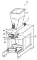
以下、本発明の粉体充填装置について、添付の図面に示す好適実施形態に基づいて説明する。図1は本発明の一実施形態を示す斜視図、図2は同実施形態の断面図である。図に示すように、この実施形態の粉体充填装置10は、粉体貯留部としてのホッパー12に貯留された粉体を、ホッパー12の下方に配置された第1のスクリューコンベア14で水平方向に移送し、この第1のスクリューコンベア14の粉体移送方向における下流側の終端部に配置された第2のスクリューコンベア16で下向きに移送して、第2のスクリューコンベア16の直下に設けられた粉体の充填ノズル18から収納袋20に粉体を供給するものである。収納袋20としては、4辺のうちの1辺が開口した通常の袋を利用でき、樹脂製、紙製、またはそれらの多層体等からなる、充填量に応じた各種のサイズの袋を用いることができる。
Hereinafter, a powder filling apparatus of the present invention will be described based on preferred embodiments shown in the accompanying drawings. FIG. 1 is a perspective view showing an embodiment of the present invention, and FIG. 2 is a cross-sectional view of the embodiment. As shown in the figure, the
粉体貯留部としてのホッパー12には、従来技術と同様に、粉体がブリッジを形成して粉体の流下を阻害することのないように、ホッパー12の内部に粉体を攪拌する攪拌装置22を有することが望ましい。この攪拌装置22は、図示するように、回転する軸24の周りに棒状の突起26を設けてモータ28で駆動するものなどを好適に使用することができる。この実施形態においては、攪拌装置22は、従来の同種の装置に比して高速(例えば、最高回転数400rpm程度)で回転され、ホッパー12において粉体を十分に攪拌する。
In the
ホッパー12の下方には、粉体貯留部としてのホッパー12から流下して供給される粉体を水平方向に移送する第1のスクリューコンベア(スクリューフィーダ)14が設けられている。この実施形態の第1のスクリューコンベア14は、粉体を移送するための通常のスクリューコンベアであり、外筒30の内面と僅かな間隙を保って回転するスクリュー32がモータ34によって駆動されて粉体を移送する。モータ34によるスクリュー32の回転は、後述する計量装置62によって、収納袋20への粉体の充填量に応じて制御される。この実施形態においては、スクリュー32は、例えば、0rpm〜2500rpmの範囲で回転する。
Below the
第2のスクリューコンベア16は、第1のスクリューコンベア14と同様のスクリューコンベアであり、外筒36の内面と僅かな間隙を保って回転するスクリュー38がモータ40によって駆動されて粉体を移送する。ここで、この実施形態では、第1のスクリューコンベア14の粉体移送方向における下流側の終端部に、第2のスクリューコンベア16の回転軸が鉛直に配置されている。
The
第1のスクリューコンベア14と第2のスクリューコンベア16との間隙には、第1のスクリューコンベア14と第2のスクリューコンベア16とを接続するゴムなどの可撓性の弾性体からなる接続部材42が設けられている。これにより、第1のスクリューコンベア14と第2のスクリューコンベア16とが重量的に縁を切られ、後述するように、計量装置62によって、第2のスクリューコンベア16に入った粉体の重量を正確に計測できるようにされている。この接続部材42は、図2では可撓性であることを明確に示すためにベローズ状に描かれているが、実際には、粉体が滞留することを防止するために、少なくとも内面は平滑なチューブ状となっていることが望ましい。また、接続部材42およびその周辺の、第1のスクリューコンベア14と第2のスクリューコンベア16との接続部は、第1のスクリューコンベア14の断面積と同等の面積を有しており、ラッパ管(縮径管)を用いた従来の装置のように、この接続部に粉体が詰まることがないので、粉体を高速で移送できる。
In the gap between the
第2のスクリューコンベア16は、スクリュー38の回転によって、第1のスクリューコンベア14によって移送されてきた粉体を引き込んで、鉛直下方に移送し、第2のスクリューコンベア16の下端に設けられた充填ノズル18から収納袋20に粉体を充填する。
The
また、スクリュー38は、第1のスクリューコンベア14のスクリュー32や従来装置のスクリューコンベアに用いられるスクリューに比べて短くされているため、偏心量の許容範囲において、従来のスクリューよりも高速で回転させることができる。この実施形態では、スクリュー38は、例えば、常に約2500rpmで回転する。すなわち、第1のスクリューコンベア14のスクリュー32と同等かそれよりも速い速度で回転する。
Moreover, since the
第2のスクリューコンベア16の下側に位置する粉体移送方向における下流側の終端部には、供給する粉体を収納袋20に充填するための充填ノズル18が配置されている。この充填ノズル18は、図3(a)に断面図を、図3(b)に下面図を示すように、第2のスクリューコンベア16の直下に配置されたほぼ楕円形の突起した形状であって、中央に粉体を供給する充填口44が、長軸に沿ったその両側に粉体とともに供給された空気を排出する排気孔46が形成されている。
A filling
この充填ノズル18は、充填口44が第2のスクリューコンベア16の外筒36の内径とほぼ同径かやや大径となる寸法で接続されており、第2のスクリューコンベア16で移送された粉体は、そのまま充填ノズル18の充填口44を通過して収納袋20に充填される。このとき、粉体と同時に空気が移送されてくるので、この空気を収納袋20から排出するために排気孔46が形成されている。この排気孔46は、充填口44の上部に配置された空気室48を経て、パイプ50を通って外部に排出される。このとき、任意の吸引装置を使用することによって、より効率的に排気することができる。
The filling
この充填ノズル18からの充填の際、充填ノズル18から排出される粉体には、第2のスクリューコンベア16での移送によって回転運動の慣性と遠心力が作用しているため、収納袋20に充填された粉体は、中央部に集中して積み上がってしまうことがなく、収納袋20の底部のほぼ全体に散布されるので、ほぼ平坦な充填面(充填された粉体の上面)が得られる。
At the time of filling from the filling
ホッパー12の攪拌装置22の近傍、第1のスクリューコンベア14の粉体移送方向における下流側の終端部の近傍、および、第2のスクリューコンベア16の充填ノズル18の近傍には、それぞれ、脱気口100,102,104が設けられている。脱気口100,102,104は、攪拌によって粉体に混入し、粉体と共に移送される空気を粉体充填装置10の外部に排出するためのもので、粉体充填装置10の各部の壁等に配されたフィルタ100a,102a,104aと、これらのフィルタを通して排気された空気を回収する脱気管100b,102b,104b等から構成される。また、脱気管100b,102b,104bには、図示しない吸気装置が接続されている。
In the vicinity of the stirring device 22 of the
フィルタ100a,102a,104aとしては、従来用いられている金網やパンチングメタル等のフィルタを始め、本出願人に係る、特開2000−335748号公報、特開平8−231051号公報等に開示されるフィルタ等が好適に利用される。吸気装置によって吸引されることにより、粉体充填装置10内の空気がフィルタ100a,102a,104aを通過して排出され、粉体充填装置10内の粉体が脱気される。
The
なお、この実施形態では、脱気口を、粉体の攪拌量の大きい上記の3箇所に設けることにより、脱気の効果を高めているが、本発明はこれには限定されず、これらのうちいずれか1つまたは2つが設けられていてもよい。 In this embodiment, the effect of deaeration is enhanced by providing the deaeration ports at the above three locations where the stirring amount of the powder is large. However, the present invention is not limited to this, and these Any one or two of them may be provided.
収納袋20は、充填ノズル18の下方の位置に、収納袋保持装置52によって吊り下げて保持される。この収納袋保持装置52は、収納袋20の供給装置(図示しない)で充填ノズル18の位置に供給され、上側の開口部を開いて充填ノズル18に被せるように配置された収納袋20を、吊り下げた状態で充填ノズル18に密着するように押し付けて保持するものであって、充填ノズル18の楕円形の突起した形状に対応する形状の2個の収納袋保持アーム54と、この収納袋保持アーム54を開閉する保持アーム駆動機構56とからなっている。そして、収納袋保持アーム54の収納袋20に接する面には、収納袋20を確実に充填ノズル18に密着させるために、ゴムなどの弾性体による押圧部材58を配置しておくことが望ましい。
The
この実施形態の保持アーム駆動機構56は、図1に示すように、ロータリーシリンダ60によって収納袋保持アーム54を揺動させるものであって、図2に想像線で示すように、ロータリーシリンダ60が回動することによって収納袋保持アーム54を揺動し、収納袋20を保持し、あるいは開放する。
As shown in FIG. 1, the holding
充填ノズル18の後方(図2では右側)の位置には、収納袋20に充填された粉体の重量を計量する計量装置62が設けられている。この計量装置62は、充填ノズル18に吊り下げた状態で保持されている収納袋20に充填される粉体の重量を、充填中に即時に計測するもので、第2のスクリューコンベア16、充填ノズル18、収納袋保持装置52およびこれらに取り付けられた部品等を一体で支持することによって、それらの総重量を計測し、粉体の充填による重量の増加分を計測することで、収納袋20に充填された粉体の重量を計量する。すなわち、第2のスクリューコンベア16、充填ノズル18、収納袋保持装置52を一体的に構成するとともに、これらを力の作用に関して他から独立させて、一体に構成された第2のスクリューコンベア16、充填ノズル18、収納袋保持装置52、およびその内部の粉体の総重量を計量装置62で計測する。
A measuring
収納袋20は、収納袋保持装置52の収納袋保持アーム54によって挟持されているため、従来の粉体充填装置に採用されている、収納袋の底部を支持して重量を測定する計量装置では、収納袋20およびその内部に充填された粉体の重量だけを高精度に計測することはできないが、上記の構成とすることより、充填ノズル18と収納袋保持装置52の収納袋保持アーム54とによって圧接されて保持された収納体20であっても、その充填量を高精度に実測することができる。
Since the
前述の、第1のスクリューコンベア14と第2のスクリューコンベア16との間隙に設けられたゴムなどの可撓性の弾性体からなる接続部材42は、計量装置62による充填量の計量のためにも必要であり、この接続部材42によって、第1のスクリューコンベア14が第2のスクリューコンベア16の重量を支えることがないように構成されている。このため、接続部材42は、その剛性によって計測値に誤差が生じないように、充分な可撓性を有することが必要となる。計量装置62には、従来公知の各種の計量装置を利用することができる。
The connecting
計量装置62は、収納袋20に供給された粉体の重量を測定して、第1のスクリューコンベア14を制御する。具体的には、充填開始時には、第1のスクリューコンベア14のスクリュー32の回転数を早くし、収納袋20に供給された粉体の重量が収納袋20に充填する所定の重量に近付いたときに、スクリュー32の回転を減速し、所定の重量に到達したときに、スクリュー32の回転を停止する。
The weighing
一方、第2のスクリューコンベア16のスクリュー38は、充填開始時から常時一定の高回転数で回転され、第1のスクリューコンベア14のスクリュー32の停止後も回転を継続して、第2のスクリューコンベア16と第1のスクリューコンベア14(接続部材42)との接続部64の粉体をスクリュー38で掻き落とすために所定の短い時間を経過してから停止する。
On the other hand, the
このように、第1のスクリューコンベア14の停止に遅れて第2のスクリューコンベア16を停止させることによって、第1のスクリューコンベア14と第2のスクリューコンベア16との接続部64に充満している粉体が第2のスクリューコンベア16によって掻き落とされるので、従来技術のように、停止後に少量の粉体が落ち続けたり、粉体が塊状になって落下することがなくなり、収納袋20への粉体の充填を素早く完了させることができ、かつ、高い精度で充填することができる。
Thus, the
また、第1のスクリューコンベア14のスクリュー32の回転数を上述のように制御することによって、第1のスクリューコンベア14の停止のタイミング、すなわち、充填終了のタイミングを高精度に制御することができ、高い充填精度を得ることができる。
Further, by controlling the number of rotations of the
なお、第2のスクリューコンベア16のスクリュー38は、充填開始、あるいはその所定時間前から、充填完了(第1のスクリューコンベア14の停止の所定時間後)、あるいはその所定時間後まで、一定の速度で回転させればよいが、必要に応じて、第1のスクリューコンベア14のスクリュー32の回転を減速するのと同期して、第2のスクリューコンベア16のスクリュー38の回転を減速させてもよい。
The
次に、本発明に関連する参考例について説明する。 Next, reference examples related to the present invention will be described.
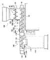
図4は本発明の一参考例を示す断面図である。図に示すように、この参考例の粉体充填装置106は、先の実施形態と同様に、粉体貯留部としてのホッパー12に貯留された粉体を、ホッパー12の下方に配置された第1のスクリューコンベア14でほぼ水平方向に移送し、この第1のスクリューコンベア14の粉体移送方向における下流側の終端部に配置された第2のスクリューコンベア108でさらに水平方向に移送して、第2のスクリューコンベア108の外筒110の下側の開放部に設けられた粉体の充填ノズル112から、収納袋114に粉体を供給するものである。
FIG. 4 is a cross-sectional view showing a reference example of the present invention. As shown in the figure, in the
この参考例は、先の実施形態と同様のホッパー12および第1のスクリューコンベア14を有しているので、ホッパー12および第1のスクリューコンベア14は、先の実施形態と同じ符号を付して説明を省略する。
Since this reference example has the
また、第1のスクリューコンベア14と第2のスクリューコンベア108との間の接続部材116は、先の実施形態と同様に、図4には可撓性であることを明確に示すためにベローズ状に描かれているが、実際には、粉体が滞留することを防止するために、少なくとも内面は平滑なチューブ状となっていることが望ましいことは、先の実施形態と同様である。
Also, the connecting
第2のスクリューコンベア108は、先の実施形態とは異なり、第1のスクリューコンベア14から、ゴムなどの可撓性の弾性体からなる接続部材116を介して直接接続されており、そのスクリュー118を回転する回転軸が水平に配置されている。接続部材116および第2のスクリューコンベア108は、ともに第1のスクリューコンベア14と同等の断面積を有している。
Unlike the previous embodiment, the
この第2のスクリューコンベア108も第1のスクリューコンベア14と同様のスクリューコンベアであり、外筒110の内面と僅かな間隙を保って回転するスクリュー118がモータ120によって駆動されて粉体を移送する。第2のスクリューコンベア108は、スクリュー118の回転によって、第1のスクリューコンベア14によって移送されてきた粉体を引き込んで、第1のスクリューコンベア14による粉体の移送方向と同じ方向(図4中右から左)へ水平に移送する。
The
第2のスクリューコンベア108の外筒110は、その下側に開放部が設けられており、この開放部の下方に粉体を収納袋114に充填する充填ノズル112が形成されている。この充填ノズル112は、図3に示す充填ノズル18とほぼ同様であって、同様な充填口44と排気孔46を有するものであり、収納袋保持装置52と同様の収納袋保持装置で収納袋を吊り下げた状態で保持する。
The
計量装置122は、先の実施形態と同様に、収納袋114に供給された粉体の重量を測定して、第1のスクリューコンベア14を制御する。具体的には、収納袋114に供給された粉体の重量が収納袋114に充填する所定の重量に近付くまでは、第1のスクリューコンベア14のスクリュー32を高速で回転し、所定の重量に近付いたときに回転を減速し、所定の重量に到達したときに、第1のスクリューコンベア14の回転を停止する。このとき、第2のスクリューコンベア108のスクリュー118の回転は継続しており、所定の短い時間を経過してから停止する。
The weighing
以上、詳細に説明したように、本発明の粉体充填装置は、従来技術において粉体の移送速度を制限していたラッパ状に細くなった部分を有さず、さらに、第2のスクリューコンベアの粉体移送方向における下流側の終端部または第2のスクリューコンベアの下側の開放部に、充填口径の大きい充填ノズルが形成されているので、高速で粉体を送っても従来技術のように粉体が詰まることがなく、高速で粉体を収納袋に充填することができる。 As described above in detail, the powder filling apparatus according to the present invention does not have a portion that is narrowed in a trumpet shape, which has limited the transfer speed of powder in the prior art, and further includes a second screw conveyor. A filling nozzle with a large filling diameter is formed at the downstream end portion in the powder transfer direction or at the lower open portion of the second screw conveyor. Therefore, the powder can be filled in the storage bag at a high speed.
また、第1のスクリューコンベアで移送された粉体は、第1のスクリューコンベアと第2のスクリューコンベアとの接続部において充満した状態になり、この充満した状態の粉体を第2のスクリューコンベアで引き込みつつ、掻き落として充填ノズルに移送するので、第1のスクリューコンベアで移送された量だけを確実に第2のスクリューコンベアで掻き落として充填ノズルに移送できる。そのため、従来技術のように塊状の粉体が収納袋に供給されることはなく、充填量を正確に制御でき、高精度な充填が可能である。 In addition, the powder transferred by the first screw conveyor is filled at the connecting portion between the first screw conveyor and the second screw conveyor, and the filled powder is used as the second screw conveyor. Therefore, only the amount transferred by the first screw conveyor can be reliably scraped off by the second screw conveyor and transferred to the filling nozzle. Therefore, unlike the prior art, lump powder is not supplied to the storage bag, the filling amount can be accurately controlled, and high-precision filling is possible.
また、第1のスクリューコンベアの停止後に、第2のスクリューコンベアが所定時間回転し、第1のスクリューコンベアと第2のスクリューコンベアとの接続部、および第2のスクリューコンベア内部の粉体を速やかに充填ノズルに移送するので、スクリューの停止後に粉体がこぼれ続けることがなく、短時間で充填を完了することができる。これにより、充填時間の短縮を実現でき、充填効率を向上させることができる。 In addition, after the first screw conveyor is stopped, the second screw conveyor rotates for a predetermined time, and the connecting portion between the first screw conveyor and the second screw conveyor and the powder inside the second screw conveyor are promptly removed. Therefore, the powder is not continuously spilled after the screw is stopped, and the filling can be completed in a short time. Thereby, shortening of filling time can be implement | achieved and filling efficiency can be improved.
以上、本発明に係る粉体充填装置について詳細に説明したが、本発明は上記の実施形態に限定されず、本発明の主旨を逸脱しない範囲において、種々の改良や変更をしてもよいのはもちろんである。 Although the powder filling apparatus according to the present invention has been described in detail above, the present invention is not limited to the above-described embodiment, and various improvements and modifications may be made without departing from the gist of the present invention. Of course.
10 粉体充填装置
12 ホッパー
14 第1のスクリューコンベア
16 第2のスクリューコンベア
18 充填ノズル
20 収納袋
22 攪拌装置
24 軸
26 棒状の突起
28 モータ
30,36 外筒
32,38 スクリュー
34,40 モータ
42 接続部材
44 充填口
46 排気孔
48 空気室
50 パイプ
52 収納袋保持装置
54 収納袋保持アーム
56 保持アーム駆動機構
58 押圧部材
60 ロータリーシリンダ
62 計量装置
64 接続部
100,102,104 脱気口
100a,102a,104a フィルタ
100b,102b,104b 脱気管
106 粉体充填装置
108 第2のスクリューコンベア
110 外筒
112 充填ノズル
114 収納袋
116 接続部材
118 スクリュー
120 モータ
122 計量装置
DESCRIPTION OF
Claims (3)
前記粉体貯留部の下方に配置され、前記粉体貯留部から供給される粉体をほぼ水平方向に移送する第1のスクリューコンベアと、
前記第1のスクリューコンベアの粉体移送方向における下流側の終端部に、回転軸が鉛直に配置された第2のスクリューコンベアと、
前記第2のスクリューコンベアの直下に設けられた粉体の充填ノズルと、
前記粉体の充填ノズルの下方に位置する粉体を収納する収納袋を保持する収納袋保持装置とを有する粉体充填装置であって、
前記第2のスクリューコンベア、前記粉体の充填ノズルおよび前記収納袋保持装置は、一体的に構成されており、かつ、前記第1のスクリューコンベアと前記第2のスクリューコンベアとが重量的に絶縁されており、
前記一体的に構成された前記第2のスクリューコンベア、前記粉体の充填ノズルおよび前記収納袋保持装置を支持してその総重量を計測することにより、前記収納袋保持装置に保持された前記収納袋に供給された粉体の重量を計測する計量装置を有することを特徴とする粉体充填装置。 A powder storage unit that has a hopper and stores powder in the hopper;
A first screw conveyor that is disposed below the powder storage unit and transfers the powder supplied from the powder storage unit in a substantially horizontal direction;
A second screw conveyor in which a rotation axis is vertically arranged at a downstream end portion in the powder transfer direction of the first screw conveyor;
A powder filling nozzle provided directly below the second screw conveyor ;
A powder filling device having a storage bag holding device for holding a storage bag for storing powder located below the powder filling nozzle,
The second screw conveyor, the powder filling nozzle, and the storage bag holding device are integrally configured, and the first screw conveyor and the second screw conveyor are insulated in terms of weight. Has been
The storage held by the storage bag holding device by supporting the integrally configured second screw conveyor, the powder filling nozzle and the storage bag holding device and measuring the total weight thereof. A powder filling apparatus comprising a weighing device for measuring the weight of powder supplied to a bag .
Priority Applications (1)
| Application Number | Priority Date | Filing Date | Title |
|---|---|---|---|
| JP2004018001A JP4402967B2 (en) | 2004-01-27 | 2004-01-27 | Powder filling equipment |
Applications Claiming Priority (1)
| Application Number | Priority Date | Filing Date | Title |
|---|---|---|---|
| JP2004018001A JP4402967B2 (en) | 2004-01-27 | 2004-01-27 | Powder filling equipment |
Publications (3)
| Publication Number | Publication Date |
|---|---|
| JP2005212795A JP2005212795A (en) | 2005-08-11 |
| JP2005212795A5 JP2005212795A5 (en) | 2006-08-31 |
| JP4402967B2 true JP4402967B2 (en) | 2010-01-20 |
Family
ID=34902640
Family Applications (1)
| Application Number | Title | Priority Date | Filing Date |
|---|---|---|---|
| JP2004018001A Expired - Lifetime JP4402967B2 (en) | 2004-01-27 | 2004-01-27 | Powder filling equipment |
Country Status (1)
| Country | Link |
|---|---|
| JP (1) | JP4402967B2 (en) |
Cited By (3)
| Publication number | Priority date | Publication date | Assignee | Title |
|---|---|---|---|---|
| CN105151338A (en) * | 2015-08-28 | 2015-12-16 | 镇江宝纳电磁新材料有限公司 | Overflowed powder collection device |
| KR200481487Y1 (en) * | 2015-01-07 | 2016-10-10 | (주)타래박 | Flour mixed packing equipment |
| CN109592089A (en) * | 2018-12-21 | 2019-04-09 | 杨新翰 | A kind of automatic packing of medical drugs is set |
Families Citing this family (10)
| Publication number | Priority date | Publication date | Assignee | Title |
|---|---|---|---|---|
| JP4427432B2 (en) * | 2004-11-05 | 2010-03-10 | 株式会社日清製粉グループ本社 | Powder filling method |
| JP2007302279A (en) * | 2006-05-10 | 2007-11-22 | Nisshin Seifun Group Inc | Powder filling device |
| JP4785610B2 (en) * | 2006-05-10 | 2011-10-05 | 株式会社日清製粉グループ本社 | Powder filling and packaging method and powder filling and packaging system |
| JP4531743B2 (en) * | 2006-12-26 | 2010-08-25 | 三菱化学エンジニアリング株式会社 | Powder deaerator |
| CN104085543A (en) * | 2014-06-27 | 2014-10-08 | 长兴明晟冶金炉料有限公司 | Castable packaging device |
| CN105599931A (en) * | 2016-03-04 | 2016-05-25 | 无锡中阳包装技术有限公司 | Dye packing machine |
| KR101873291B1 (en) * | 2017-10-02 | 2018-07-31 | 윤정원 | Powder filling machine |
| CN112193446A (en) * | 2020-09-17 | 2021-01-08 | 祁东纯之绿食品有限公司 | Nitrogen-filled packaging device for small-package daylily |
| CN112009739A (en) * | 2020-09-25 | 2020-12-01 | 丁苏琴 | Rice processing filling machine with quantitative filling function |
| CN115892551A (en) * | 2022-12-08 | 2023-04-04 | 辽宁润兴新材料有限公司 | Cladding material production equipment for packing |
Family Cites Families (28)
| Publication number | Priority date | Publication date | Assignee | Title |
|---|---|---|---|---|
| JPS5113077B1 (en) * | 1971-04-02 | 1976-04-24 | ||
| JPS5548024A (en) * | 1978-09-25 | 1980-04-05 | Ube Industries | Pulverulent and granular body bagger |
| JPS5830902A (en) * | 1981-08-14 | 1983-02-23 | 大和製衡株式会社 | Vacuum deairing type filler |
| JPS58171802U (en) * | 1982-05-13 | 1983-11-16 | 岡村製油株式会社 | bagging equipment |
| JPS60123301A (en) * | 1983-11-29 | 1985-07-02 | 日清製粉株式会社 | Powdered and granular body filler and method of controlling operation of said filler |
| JPH07115694B2 (en) * | 1987-12-15 | 1995-12-13 | 株式会社中島製作所 | Granule filling device |
| JPH0547041Y2 (en) * | 1988-08-11 | 1993-12-10 | ||
| ATE131443T1 (en) * | 1991-01-29 | 1995-12-15 | Buehler Ag | METHOD FOR BAGING SPECIFIC BULK QUANTITIES AND A BULK BAGING DEVICE |
| JPH0815897B2 (en) * | 1992-04-10 | 1996-02-21 | 鎌長製衡株式会社 | Powder filling machine |
| JP3184943B2 (en) * | 1992-06-02 | 2001-07-09 | 株式会社フジタ | Sediment removal equipment in a shaft |
| JPH06199302A (en) * | 1993-01-07 | 1994-07-19 | Yamato Scale Co Ltd | Deaerating type powder filling machine |
| JPH0740924A (en) * | 1993-07-30 | 1995-02-10 | General Patsukaa Kk | Apparatus for filling object in wrapping machine |
| JPH07100188A (en) * | 1993-09-11 | 1995-04-18 | Tokyo Shokai:Kk | Powdered medicine feeder |
| US5423950A (en) * | 1993-10-28 | 1995-06-13 | Texaco Inc. | Method and reactor for producing tire oil |
| JP3448385B2 (en) * | 1995-02-23 | 2003-09-22 | 日清製粉株式会社 | Operating method of powder filling device with deaeration mechanism |
| JP3167957B2 (en) * | 1997-04-28 | 2001-05-21 | 株式会社ケーテー製作所 | Powder filling equipment |
| JPH114621A (en) * | 1997-06-16 | 1999-01-12 | Yanmar Agricult Equip Co Ltd | Grain transfer unit |
| JPH11164628A (en) * | 1997-12-04 | 1999-06-22 | Owaki Kogyo Kk | Automatic chaff feeder and underdrain layer |
| JP2000109001A (en) * | 1998-10-08 | 2000-04-18 | Haga Kensetsu:Kk | Bag folling device |
| JP4275779B2 (en) * | 1998-10-29 | 2009-06-10 | 日清製粉株式会社 | Filling and packing machine for powder and granule with a small amount of addition equipment |
| JP2000142601A (en) * | 1998-10-30 | 2000-05-23 | Yasuo Kawachi | Sandbag manufacturing apparatus and sandbag manufacturing plant |
| JP3336290B2 (en) * | 1999-04-30 | 2002-10-21 | ツカサ工業株式会社 | Powder filling equipment |
| JP3153206B2 (en) * | 1999-05-24 | 2001-04-03 | 日清製粉株式会社 | Powder filling apparatus and operating method thereof |
| JP3453097B2 (en) * | 2000-02-08 | 2003-10-06 | ニューロング株式会社 | Metering and filling equipment |
| JP4067745B2 (en) * | 2000-07-06 | 2008-03-26 | 株式会社東京自働機械製作所 | Powder filling device |
| JP3908510B2 (en) * | 2001-11-14 | 2007-04-25 | 株式会社リコー | Powder feeder |
| JP2003200901A (en) * | 2002-01-10 | 2003-07-15 | Nisshin Seifun Group Inc | Bagging tube for powdered material |
| JP3993472B2 (en) * | 2002-06-18 | 2007-10-17 | 三菱重工業株式会社 | Operation control method of gasification furnace for coal gasification combined power plant |
-
2004
- 2004-01-27 JP JP2004018001A patent/JP4402967B2/en not_active Expired - Lifetime
Cited By (3)
| Publication number | Priority date | Publication date | Assignee | Title |
|---|---|---|---|---|
| KR200481487Y1 (en) * | 2015-01-07 | 2016-10-10 | (주)타래박 | Flour mixed packing equipment |
| CN105151338A (en) * | 2015-08-28 | 2015-12-16 | 镇江宝纳电磁新材料有限公司 | Overflowed powder collection device |
| CN109592089A (en) * | 2018-12-21 | 2019-04-09 | 杨新翰 | A kind of automatic packing of medical drugs is set |
Also Published As
| Publication number | Publication date |
|---|---|
| JP2005212795A (en) | 2005-08-11 |
Similar Documents
| Publication | Publication Date | Title |
|---|---|---|
| JP4402967B2 (en) | Powder filling equipment | |
| ES2242923T3 (en) | PROCEDURE AND APPLIANCE FOR THE TRANSPORTATION OF FINE POWDER. | |
| WO2007100141A1 (en) | Powder-filling device, powder-filling method, and process cartridge | |
| JP4785610B2 (en) | Powder filling and packaging method and powder filling and packaging system | |
| JP5259694B2 (en) | Powder filling device with powder supply device | |
| JP2018114281A (en) | Medicine put-out device, powder weighing device, and medicine dispensing system | |
| JPH06329102A (en) | Fixed quantity filling device for powder and its related device | |
| JP2005289379A (en) | Powder filling apparatus and its operating method | |
| JP3127284U (en) | Powder feeder | |
| JP2815895B2 (en) | Powder feeder | |
| JP4427432B2 (en) | Powder filling method | |
| JP2007302279A (en) | Powder filling device | |
| JP4193807B2 (en) | Method for filling powder into container | |
| JP2007153396A (en) | Powder deaerator | |
| JP3262212B2 (en) | Method and apparatus for replenishing powder to powder feeder and powder feeder | |
| JP2003237701A (en) | Quantitative feeding apparatus and packaging machine for powder | |
| JP2010189073A (en) | Fixed quantity feeder device for powder | |
| JP4384969B2 (en) | Granule filling device and powder filling method | |
| JP2005320066A (en) | Packaging-bag loading device | |
| JP2003237886A (en) | Dispensing and feeding apparatus for granulated dry ice and continuous feeding system for granulated dry ice | |
| JP2001333609A (en) | Apparatus for coating seed | |
| KR100650286B1 (en) | Method and apparatus for automatically packaging medicine powder | |
| WO2021171799A1 (en) | Powdered medicine division and packaging device | |
| EP1595795B1 (en) | Device for supplying/dosing packaged tablets for the food industry | |
| JPH0230649B2 (en) | FUNTAINOHARAIDASHISOCHI |
Legal Events
| Date | Code | Title | Description |
|---|---|---|---|
| A521 | Request for written amendment filed |
Free format text: JAPANESE INTERMEDIATE CODE: A523 Effective date: 20060713 |
|
| A621 | Written request for application examination |
Free format text: JAPANESE INTERMEDIATE CODE: A621 Effective date: 20060713 |
|
| A977 | Report on retrieval |
Free format text: JAPANESE INTERMEDIATE CODE: A971007 Effective date: 20090313 |
|
| A131 | Notification of reasons for refusal |
Free format text: JAPANESE INTERMEDIATE CODE: A131 Effective date: 20090414 |
|
| A521 | Request for written amendment filed |
Free format text: JAPANESE INTERMEDIATE CODE: A523 Effective date: 20090612 |
|
| TRDD | Decision of grant or rejection written | ||
| A01 | Written decision to grant a patent or to grant a registration (utility model) |
Free format text: JAPANESE INTERMEDIATE CODE: A01 Effective date: 20091027 |
|
| A01 | Written decision to grant a patent or to grant a registration (utility model) |
Free format text: JAPANESE INTERMEDIATE CODE: A01 |
|
| A61 | First payment of annual fees (during grant procedure) |
Free format text: JAPANESE INTERMEDIATE CODE: A61 Effective date: 20091030 |
|
| R150 | Certificate of patent or registration of utility model |
Ref document number: 4402967 Country of ref document: JP Free format text: JAPANESE INTERMEDIATE CODE: R150 Free format text: JAPANESE INTERMEDIATE CODE: R150 |
|
| FPAY | Renewal fee payment (event date is renewal date of database) |
Free format text: PAYMENT UNTIL: 20121106 Year of fee payment: 3 |
|
| FPAY | Renewal fee payment (event date is renewal date of database) |
Free format text: PAYMENT UNTIL: 20121106 Year of fee payment: 3 |
|
| FPAY | Renewal fee payment (event date is renewal date of database) |
Free format text: PAYMENT UNTIL: 20131106 Year of fee payment: 4 |
|
| R250 | Receipt of annual fees |
Free format text: JAPANESE INTERMEDIATE CODE: R250 |
|
| R250 | Receipt of annual fees |
Free format text: JAPANESE INTERMEDIATE CODE: R250 |
|
| R250 | Receipt of annual fees |
Free format text: JAPANESE INTERMEDIATE CODE: R250 |
|
| R250 | Receipt of annual fees |
Free format text: JAPANESE INTERMEDIATE CODE: R250 |
|
| R250 | Receipt of annual fees |
Free format text: JAPANESE INTERMEDIATE CODE: R250 |
|
| R250 | Receipt of annual fees |
Free format text: JAPANESE INTERMEDIATE CODE: R250 |
|
| R250 | Receipt of annual fees |
Free format text: JAPANESE INTERMEDIATE CODE: R250 |
|
| R250 | Receipt of annual fees |
Free format text: JAPANESE INTERMEDIATE CODE: R250 |
|
| R250 | Receipt of annual fees |
Free format text: JAPANESE INTERMEDIATE CODE: R250 |
|
| R250 | Receipt of annual fees |
Free format text: JAPANESE INTERMEDIATE CODE: R250 |
|
| R250 | Receipt of annual fees |
Free format text: JAPANESE INTERMEDIATE CODE: R250 |
|
| R250 | Receipt of annual fees |
Free format text: JAPANESE INTERMEDIATE CODE: R250 |
|
| EXPY | Cancellation because of completion of term |