JP2005320066A - Packaging-bag loading device - Google Patents

Packaging-bag loading device Download PDF

Info

Publication number
JP2005320066A
JP2005320066A JP2004365801A JP2004365801A JP2005320066A JP 2005320066 A JP2005320066 A JP 2005320066A JP 2004365801 A JP2004365801 A JP 2004365801A JP 2004365801 A JP2004365801 A JP 2004365801A JP 2005320066 A JP2005320066 A JP 2005320066A
Authority
JP
Japan
Prior art keywords
packaging bag
powder
filling nozzle
filling
holding
Prior art date
Legal status (The legal status is an assumption and is not a legal conclusion. Google has not performed a legal analysis and makes no representation as to the accuracy of the status listed.)
Pending
Application number
JP2004365801A
Other languages
Japanese (ja)
Other versions
JP2005320066A5 (en
Inventor
Makoto Doi
眞 土井
Current Assignee (The listed assignees may be inaccurate. Google has not performed a legal analysis and makes no representation or warranty as to the accuracy of the list.)
Nisshin Seifun Group Inc
Original Assignee
Nisshin Seifun Group Inc
Priority date (The priority date is an assumption and is not a legal conclusion. Google has not performed a legal analysis and makes no representation as to the accuracy of the date listed.)
Filing date
Publication date
Application filed by Nisshin Seifun Group Inc filed Critical Nisshin Seifun Group Inc
Priority to JP2004365801A priority Critical patent/JP2005320066A/en
Publication of JP2005320066A publication Critical patent/JP2005320066A/en
Publication of JP2005320066A5 publication Critical patent/JP2005320066A5/ja
Pending legal-status Critical Current

Links

Images

Landscapes

  • Supply Of Fluid Materials To The Packaging Location (AREA)
  • Basic Packing Technique (AREA)

Abstract

<P>PROBLEM TO BE SOLVED: To provide a packaging-bag loading device for a powder filling apparatus that highly accurately fills each packaging bag with powder at a high speed. <P>SOLUTION: The device includes a filling nozzle having a filling port for supplying powder and filling each packaging bag with the powder and an exhaust port for drawing out air, supplied with the powder at the same time, from the packaging bag. The device also includes a pair of packaging-bag hold arms, each having such a shape (curved shape) that its central section is in almost close contact with the outer circumference of the filling nozzle and both its ends stick out from the filling nozzle. The device further includes a hold arm opening/closing mechanism for opening or closing the pair of packaging-bag hold arms. The packaging bag to be filled with the powder is held between the periphery of the filling nozzle and the pair of packaging-bag hold arms. <P>COPYRIGHT: (C)2006,JPO&NCIPI

Description

本発明は、小麦粉などの粉体を包装袋に充填する粉体充填装置の粉体充填部に利用される包装袋の装着装置に関するものである。   The present invention relates to a packaging bag mounting device used in a powder filling unit of a powder filling device for filling powder such as wheat flour into a packaging bag.

粉体、特に小麦粉のような微細な粉体を供給して包装袋に充填するための粉体充填装置150は、従来技術では、図10に示すように、粉体貯留部としてのホッパー152と、ホッパー152の下方に配置され、ホッパー152から流下する粉体をほぼ水平方向に移送する第1のスクリューコンベア154と、この第1のスクリューコンベア154のさらに下方に配置され、この第1のスクリューコンベア154で移送されて、第1のスクリューコンベア154の下側に設けられた開口部から流下した粉体を、さらにほぼ水平方向に移送する第2のスクリューコンベア156とを有しており、この第2のスクリューコンベア156で移送された粉体を充填ノズル158から吐出して包装袋160に充填するようになっている。   In the prior art, a powder filling device 150 for supplying fine powder such as wheat flour and filling the packaging bag is, as shown in FIG. 10, a hopper 152 as a powder reservoir, The first screw conveyor 154 is disposed below the hopper 152 and transfers the powder flowing down from the hopper 152 in a substantially horizontal direction, and is further disposed below the first screw conveyor 154. A second screw conveyor 156 that transfers the powder that has been transferred by the conveyor 154 and has flowed from an opening provided on the lower side of the first screw conveyor 154 in a substantially horizontal direction. The powder transferred by the second screw conveyor 156 is discharged from the filling nozzle 158 and filled in the packaging bag 160.

この粉体充填装置150には、ホッパー152の内部に、ホッパー152内の粉体がブリッジを形成することを防止するための攪拌装置162が設けられており、第1のスクリューコンベア154の粉体移送方向における下流側の終端部および必要なときには第2のスクリューコンベア156の粉体移送方向における下流側の終端部に、粉体とともに移送される空気を排出する排気孔164が設けられている。   The powder filling device 150 is provided with a stirring device 162 for preventing the powder in the hopper 152 from forming a bridge inside the hopper 152, and the powder of the first screw conveyor 154. Exhaust holes 164 for discharging the air transferred together with the powder are provided at the downstream end portion in the transfer direction and, if necessary, at the downstream end portion in the powder transfer direction of the second screw conveyor 156.

第2のスクリューコンベア156の粉体移送方向における下流側に配置された充填ノズル158は、包装袋160の上部側面に設けられた小さい開口部(図示しない)に挿入されて粉体を供給する。そのため、充填ノズル158は、第2のスクリューコンベア156の内径よりも小径にする必要があり、第2のスクリューコンベア156と充填ノズル158との接続部は、ラッパ状に細くなるように形成されている。ノズル158の先端には吐出口166が斜め下方に向かって開口して設けられている。また、包装袋160は、その底部が支持フレーム168に支持されており、包装袋160に充填された粉体の重量は、計量装置170によって、支持フレーム168とともに計測される。   The filling nozzle 158 arranged on the downstream side in the powder transfer direction of the second screw conveyor 156 is inserted into a small opening (not shown) provided on the upper side surface of the packaging bag 160 to supply the powder. Therefore, it is necessary to make the filling nozzle 158 smaller in diameter than the inner diameter of the second screw conveyor 156, and the connecting portion between the second screw conveyor 156 and the filling nozzle 158 is formed to be thin in a trumpet shape. Yes. A discharge port 166 is provided at the tip of the nozzle 158 so as to open obliquely downward. Further, the bottom of the packaging bag 160 is supported by the support frame 168, and the weight of the powder filled in the packaging bag 160 is measured together with the support frame 168 by the measuring device 170.

このような粉体充填装置は、例えば、特許文献1、特許文献2などに記載されている。
特開平8−337321号公報 特開2000−128102号公報
Such a powder filling apparatus is described in, for example, Patent Document 1, Patent Document 2, and the like.
JP-A-8-337321 JP 2000-128102 A

従来技術の粉体充填装置150は、上記のように、第2のスクリューコンベア156の内径より充填ノズル158の内径が細くなっており、その接続部にラッパ状に縮径する部分が設けられているので、短時間で粉体の充填を行うために粉体を高速で移送しようとすると、そのラッパ状に縮径する部分(ラッパ管)に粉体が詰まり易く、また、吐出口166の径も大きくないので、粉体を短時間で包装袋に充填するのには必ずしも適した構造ではなかった。   As described above, the powder filling device 150 of the prior art has the inner diameter of the filling nozzle 158 smaller than the inner diameter of the second screw conveyor 156, and a connecting portion is provided with a portion that is reduced in a trumpet shape. Therefore, if the powder is to be transferred at a high speed in order to fill the powder in a short time, the powder is likely to be clogged in the portion that is reduced in the trumpet shape (the trumpet tube), and the diameter of the discharge port 166 Therefore, the structure is not necessarily suitable for filling the packaging bag with the powder in a short time.

また、充填ノズル158の吐出口166は、単に斜め下方に向かって開口しているのみの形状であり、充填ノズル158の内部で押し固められた粉体は、吐出口166の位置で割れて塊状となって落下するので、包装袋160に供給される粉体の量を高い精度で制御することは難しかった。   In addition, the discharge port 166 of the filling nozzle 158 has a shape that is merely opened obliquely downward, and the powder compacted inside the filling nozzle 158 is broken into a lump at the position of the discharge port 166. Therefore, it is difficult to control the amount of powder supplied to the packaging bag 160 with high accuracy.

このため、高速かつ高精度の充填を目的として、包装袋160として上端辺が開放された包装袋を用い、充填ノズル158のラッパ状に縮径する部分を無くして、広口の充填ノズルによって粉体を充填することが検討された。包装袋160として、上端辺が開放された包装袋を用いる場合、その粉体充填装置に採用される包装袋160の保持装置としては、次のような性能が要求される。   For this reason, for the purpose of high-speed and high-precision filling, a packaging bag having an open upper end is used as the packaging bag 160, and the portion of the filling nozzle 158 that is reduced in a trumpet shape is eliminated. It was considered to fill. When a packaging bag having an open upper end is used as the packaging bag 160, the following performance is required as a holding device for the packaging bag 160 employed in the powder filling apparatus.

すなわち、包装袋160の保持装置は、包装袋160に充填される粉体が舞い上がって周囲に飛散しないように、包装袋160の開口部を充填ノズル158に密着させるとともに、開口部の全体を略密閉して保持するものである必要がある。   That is, the holding device for the packaging bag 160 causes the opening of the packaging bag 160 to be in close contact with the filling nozzle 158 so that the powder filled in the packaging bag 160 does not fly up and scatter to the surroundings. It must be sealed and held.

包装袋160の開口部を充填ノズル158に密着させるように保持する形態とした場合、充填中の包装袋160およびその内容物の荷重は、充填ノズル158側にも支持されることになる。このような形態の粉体充填装置において充填量を高精度に制御するためには、充填ノズル158に包装袋160を吊り下げた状態で、包装袋160の保持部のみで包装袋160の全重量を支えて、その重量を計測する方法が考えられる。その場合、包装袋160の保持装置は、包装袋160の全重量(例えば25kg)を支えられるだけの強固な保持力を有することが要求される。   When it is set as the form which hold | maintains so that the opening part of the packaging bag 160 may be closely_contact | adhered to the filling nozzle 158, the load of the packaging bag 160 and its content during filling will also be supported also to the filling nozzle 158 side. In order to control the filling amount with high accuracy in the powder filling apparatus having such a configuration, with the packaging bag 160 suspended from the filling nozzle 158, the entire weight of the packaging bag 160 is obtained only by the holding portion of the packaging bag 160. It is conceivable to measure the weight by supporting In that case, the holding device for the packaging bag 160 is required to have a strong holding force that can support the entire weight (for example, 25 kg) of the packaging bag 160.

また、包装袋160の保持装置は、異なるサイズの包装袋にも対応できるものであるのが好ましい。しかしながら、これらの性能を具備する包装袋の装着装置は知られていない。   Moreover, it is preferable that the holding device of the packaging bag 160 is compatible with packaging bags of different sizes. However, a packaging bag mounting device having these performances is not known.

また、包装袋160に粉体を充填した後に包装を完了するためには、例えば従来の脱気装置、整形装置、ヒートシール装置等の装置に包装袋160を適宜搬送するために、包装袋160を次工程へ搬送する搬送手段の搬送用グリップ等が包装袋160を把持するためのスペースを確保する必要がある。従来は、包装袋160の上部に粉体が充填されない領域を確保するために包装袋160の寸法に余裕をもたせ、充填完了後に包装袋上部に粉体が充填されないスペースが生じるようにしていたが、それだけ包装袋160のサイズが大きくなりコストの増加につながっていた。   Further, in order to complete the packaging after filling the packaging bag 160 with the powder, for example, in order to appropriately transport the packaging bag 160 to an apparatus such as a conventional deaeration device, a shaping device, or a heat seal device, the packaging bag 160 is used. It is necessary to secure a space for gripping the packaging bag 160 by a transport grip or the like of a transport means for transporting the bag to the next process. Conventionally, in order to secure an area in which the powder is not filled in the upper part of the packaging bag 160, the dimension of the packaging bag 160 is provided so that a space in which the powder is not filled is formed in the upper part of the packaging bag after the filling is completed. As a result, the size of the packaging bag 160 is increased, leading to an increase in cost.

本発明の目的は、このような従来技術の問題点を解消し、上端辺が開放された開口部を有する包装袋を用い、この包装袋に粉体を高速かつ高精度で充填できる粉体充填装置において、包装袋の開口部からの粉体の飛散を防ぐことができ、かつ包装袋を確実に保持でき、さらには、異なるサイズの包装袋にも対応できる包装袋の装着装置を提供することにある。   The object of the present invention is to solve such problems of the prior art, and use a packaging bag having an opening with an open upper end, and the powder can be filled into the packaging bag at high speed and with high accuracy. To provide a packaging bag mounting device that can prevent powder from scattering from the opening of the packaging bag, can hold the packaging bag securely, and can also handle packaging bags of different sizes. It is in.

また、包装袋における、粉体が充填される領域を制限することで、充填が完了した包装袋をヒートシール等の次工程へ搬送する搬送手段の搬送用グリップ等が包装袋を把持するためのスペースを確保することができる包装袋の装着装置を提供することを目的とする。   In addition, by restricting the area in the packaging bag where the powder is filled, a grip for transporting the transporting means for transporting the packed packaging bag to the next process such as heat sealing is used for gripping the packaging bag. An object of the present invention is to provide a packaging bag mounting apparatus capable of securing a space.

上記の課題を解決するために、本発明は、粉体を供給して包装袋に充填する充填口および前記粉体と同時に供給される空気を前記包装袋から排出する排気孔を有する充填ノズルと、
中央部が前記充填ノズルの外周にほぼ密着する形状であって、両端部が前記充填ノズルの外方に突出する形状である一対の包装袋保持アームと、
前記一対の包装袋保持アームを開閉する保持アーム開閉機構とを有し、
前記粉体を充填する前記包装袋を、前記充填ノズルの外周と前記一対の包装袋保持アームとの間に挟持して保持することを特徴とする包装袋の装着装置を提供する。
In order to solve the above problems, the present invention includes a filling port for supplying powder and filling the packaging bag, and a filling nozzle having an exhaust hole for discharging air supplied simultaneously with the powder from the packaging bag; ,
A pair of packaging bag holding arms having a shape in which the central portion is substantially in close contact with the outer periphery of the filling nozzle, and both end portions are shaped to protrude outward of the filling nozzle;
A holding arm opening and closing mechanism for opening and closing the pair of packaging bag holding arms,
There is provided a packaging bag mounting device characterized in that the packaging bag filled with the powder is sandwiched and held between an outer periphery of the filling nozzle and the pair of packaging bag holding arms.

ここで、前記充填ノズルは、断面形状がほぼ楕円形であって、中央部に円形の前記充填口を有し、その両側に前記排気孔が配置されているのが好ましい。   Here, it is preferable that the filling nozzle has a substantially elliptical cross-sectional shape, has a circular filling port in the center, and the exhaust holes are arranged on both sides thereof.

さらに、前記包装袋保持アームは、前記充填ノズルに当接する前記包装袋保持アームの湾曲部の近傍の下面に付設された、前記包装袋を挟持して前記包装袋における前記粉体が充填される領域を制限する補助アームを含み、
前記補助アームの一部が、前記包装袋保持アームと平行になるように設けられていることを特徴とする包装袋の装着装置を提供する。
Furthermore, the packaging bag holding arm is attached to a lower surface in the vicinity of the curved portion of the packaging bag holding arm that contacts the filling nozzle, and the packaging bag is filled with the powder in the packaging bag. Including an auxiliary arm to limit the area,
Provided is a packaging bag mounting device, wherein a part of the auxiliary arm is provided in parallel with the packaging bag holding arm.

また、前記一対の包装袋保持アームおよび/または前記補助アームの内面には、前記包装袋を前記充填ノズルの外周に圧接する弾性体による押圧部材を有するのが好ましい。   Moreover, it is preferable that the inner surface of the pair of packaging bag holding arms and / or the auxiliary arms has a pressing member made of an elastic body that presses the packaging bag against the outer periphery of the filling nozzle.

また、前記押圧部材は、その外周面で前記包装袋を保持するチューブ状の弾性体であるのが好ましい。   Moreover, it is preferable that the said pressing member is a tube-shaped elastic body holding the said packaging bag in the outer peripheral surface.

また、前記押圧部材は、その外周面で前記包装袋を保持するための滑り止めとしての突起部を有する弾性体であるのが好ましい。   Moreover, it is preferable that the said pressing member is an elastic body which has the protrusion part as a slipper for hold | maintaining the said packaging bag in the outer peripheral surface.

また、前記一対の包装袋保持アームにおける前記充填ノズルの外方に突出する部分の長さは、前記充填ノズルに装着された前記包装袋の開口部の前記充填ノズルから突出する長さ以上であるのが好ましい。   In addition, the length of the portion of the pair of packaging bag holding arms that protrudes outward from the filling nozzle is equal to or longer than the length of the opening of the packaging bag that is mounted on the filling nozzle. Is preferred.

また、前記一対の包装袋保持アームを開閉する前記保持アーム開閉機構が、前記充填ノズルの上側に配置されているのが好ましい。
さらに、前記充填ノズルの前記排気孔には、空気とともに粉体が排出されることを防止するフィルタと、このフィルタを通して排出される空気を吸引する排気ポンプとを有するのが好ましい。
Moreover, it is preferable that the holding arm opening / closing mechanism for opening and closing the pair of packaging bag holding arms is disposed above the filling nozzle.
Furthermore, it is preferable that the exhaust hole of the filling nozzle has a filter that prevents the powder from being discharged together with air, and an exhaust pump that sucks the air discharged through the filter.

本発明は、上記のように構成されているので、広口の充填ノズルによって粉体の包装袋への充填を高速かつ高精度に行うことができる粉体充填装置において、上端辺が開放された開口部を有する包装袋を用いた場合にも、包装袋の開口部から粉体が周囲に飛散するのを防ぐことができ、かつ包装袋を確実に保持する包装袋の装着装置を提供することができる。また、本発明の包装袋の装着装置によれば、異なるサイズの包装袋にもその構成を変えることなく即時に対応することができる。   Since the present invention is configured as described above, an opening having an open upper end is provided in a powder filling apparatus capable of filling powder packaging bags at high speed and with high accuracy by a wide-mouth filling nozzle. Even when a packaging bag having a portion is used, it is possible to prevent the powder from scattering from the opening of the packaging bag and to provide a packaging bag mounting device that holds the packaging bag securely. it can. Moreover, according to the packaging bag mounting apparatus of the present invention, it is possible to immediately cope with packaging bags of different sizes without changing the configuration.

また、包装袋を次工程へ搬送する搬送手段の搬送用グリップ等が確実に包装袋を把持するためのスペースを確保することができる。また、同時に包装袋の上部をシールするシール代も確保できる。   Moreover, the conveyance grip of the conveyance means which conveys a packaging bag to the next process can ensure the space for gripping a packaging bag reliably. At the same time, a seal allowance for sealing the upper portion of the packaging bag can be secured.

さらに、補助アームは粉体が充填される領域を制限するので、搬送用グリップ等が包装袋を把持するためのスペースへの粉体の流入を考慮する必要がなくなり、包装袋を従来よりも小型なものにすることができる。これにより、包装袋製造に要する包装材料の使用量を減少させコストを削減することができる。また、粉体が充填される領域を制限することによって嵩密度を高くすることができる。   In addition, since the auxiliary arm limits the area where the powder is filled, there is no need for the conveyance grip etc. to consider the inflow of powder into the space for holding the packaging bag, and the packaging bag is smaller than before. Can be made. Thereby, the usage-amount of the packaging material required for packaging bag manufacture can be reduced, and cost can be reduced. Further, the bulk density can be increased by limiting the region where the powder is filled.

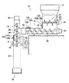
以下、本発明の包装袋の装着装置を、添付の図面に示す好適実施形態に基づいて説明する。図1は、本発明の包装袋の装着装置を採用した粉体充填装置の一例を示す斜視図、図2は、同粉体充填装置の断面図である。同図に示すように、この実施形態の粉体充填装置10は、粉体貯留部としてのホッパー12に貯留された粉体を、ホッパー12の下方に配置された第1のスクリューコンベア14で水平方向に移送し、この第1のスクリューコンベア14の粉体移送方向における下流側の終端部に配置された第2のスクリューコンベア16で下向きに移送して、第2のスクリューコンベア16の直下に設けられた粉体の充填ノズル18から包装袋20に粉体を供給するものである。包装袋20としては、4辺のうちの1辺(上端辺)が開口した通常の袋を利用でき、樹脂製、紙製、またはそれらの多層体等からなる、充填量に応じた各種のサイズの袋を用いることができる。   DESCRIPTION OF EMBODIMENTS Hereinafter, a packaging bag mounting device according to the present invention will be described based on preferred embodiments shown in the accompanying drawings. FIG. 1 is a perspective view showing an example of a powder filling apparatus employing the packaging bag mounting apparatus of the present invention, and FIG. 2 is a cross-sectional view of the powder filling apparatus. As shown in the figure, the powder filling apparatus 10 of this embodiment is configured such that the powder stored in a hopper 12 serving as a powder storage unit is horizontally placed on a first screw conveyor 14 disposed below the hopper 12. The first screw conveyor 14 is moved downward by a second screw conveyor 16 disposed at a terminal end on the downstream side in the powder transfer direction of the first screw conveyor 14, and is provided immediately below the second screw conveyor 16. The powder is supplied to the packaging bag 20 from the powder filling nozzle 18. As the packaging bag 20, a normal bag having one of the four sides (upper side) opened can be used, and various sizes according to the filling amount made of resin, paper, or a multilayer body thereof can be used. Can be used.

粉体貯留部としてのホッパー12には、従来技術と同様に、粉体がブリッジを形成して粉体の流下を阻害することのないように、ホッパー12の内部に粉体を攪拌する攪拌装置22を有することが望ましい。この攪拌装置22は、図示するように、回転する軸24の周りに棒状の突起26を設けてモータ28で駆動するものなどを好適に使用することができる。   In the hopper 12 as the powder reservoir, as in the prior art, a stirring device for stirring the powder inside the hopper 12 so that the powder does not form a bridge and hinder the flow of the powder. 22 is desirable. As the stirring device 22, as shown in the figure, a device in which a rod-like protrusion 26 is provided around a rotating shaft 24 and driven by a motor 28 can be suitably used.

ホッパー12の下方には、粉体貯留部としてのホッパー12から流下して供給される粉体を水平方向に移送する第1のスクリューコンベア(スクリューフィーダ)14が設けられている。この実施形態の第1のスクリューコンベア14は、粉体を移送するための通常のスクリューコンベアであり、外筒30の内面と僅かな間隙を保って回転するスクリュー32がモータ34によって駆動されて粉体を移送する。   Below the hopper 12, there is provided a first screw conveyor (screw feeder) 14 for horizontally transferring the powder supplied from the hopper 12 as a powder reservoir. The first screw conveyor 14 of this embodiment is a normal screw conveyor for transferring powder, and a screw 32 that rotates while maintaining a slight gap with the inner surface of the outer cylinder 30 is driven by a motor 34 to generate powder. Transport the body.

第2のスクリューコンベア16は、第1のスクリューコンベア14と同様のスクリューコンベアであり、外筒36の内面と僅かな間隙を保って回転するスクリュー38がモータ40によって駆動されて粉体を移送する。第1のスクリューコンベア14の粉体移送方向における下流側の終端部には、第2のスクリューコンベア16の回転軸が鉛直に配置されている。   The second screw conveyor 16 is a screw conveyor similar to the first screw conveyor 14, and a screw 38 that rotates with a slight gap from the inner surface of the outer cylinder 36 is driven by a motor 40 to transfer powder. . At the downstream end portion of the first screw conveyor 14 in the powder transfer direction, the rotation axis of the second screw conveyor 16 is arranged vertically.

第1のスクリューコンベア14と第2のスクリューコンベア16との間隙には、第1のスクリューコンベア14と第2のスクリューコンベア16とを接続するゴムなどの可撓性の弾性体からなる接続部材42が設けられている。これにより、第1のスクリューコンベア14と第2のスクリューコンベア16とが重量的に縁を切られ、後述するように、計量装置62によって、第2のスクリューコンベア16に入った粉体の重量を正確に計測できるようにされている。この接続部材42は、図2では可撓性であることを明確に示すためにベローズ状に描かれているが、実際には、粉体が滞留することを防止するために、少なくとも内面は平滑なチューブ状となっていることが望ましい。   In the gap between the first screw conveyor 14 and the second screw conveyor 16, a connecting member 42 made of a flexible elastic body such as rubber connecting the first screw conveyor 14 and the second screw conveyor 16. Is provided. As a result, the first screw conveyor 14 and the second screw conveyor 16 are cut off in terms of weight, and the weight of the powder that has entered the second screw conveyor 16 is reduced by the weighing device 62 as will be described later. It can be measured accurately. The connecting member 42 is depicted in a bellows shape in order to clearly show that it is flexible in FIG. 2, but in practice, at least the inner surface is smooth to prevent the powder from staying. It is desirable that it is a tube shape.

ホッパー12の攪拌装置22の近傍、第1のスクリューコンベア14の粉体移送方向における下流側の終端部の近傍、および、第2のスクリューコンベア16の充填ノズル18の近傍には、それぞれ、脱気口120,122,124が設けられている。脱気口120,122,124は、攪拌によって粉体に混入し、粉体と共に移送される空気を粉体充填装置10の外部に排出するためのもので、粉体充填装置10の各部の壁等に配されたフィルタ120a,122a,124aと、これらのフィルタを通して排気された空気を回収する脱気管120b,122b,124b等から構成される。また、脱気管120b,122b,124bには、図示しない吸気装置が接続されている。   In the vicinity of the stirring device 22 of the hopper 12, the vicinity of the downstream end portion in the powder transfer direction of the first screw conveyor 14, and the vicinity of the filling nozzle 18 of the second screw conveyor 16, respectively, deaeration Ports 120, 122, and 124 are provided. The deaeration ports 120, 122, and 124 are used for discharging the air mixed into the powder by stirring and transported together with the powder to the outside of the powder filling device 10. The filter 120a, 122a, 124a arranged in the same, deaeration pipes 120b, 122b, 124b for collecting the air exhausted through these filters, and the like. In addition, an intake device (not shown) is connected to the deaeration pipes 120b, 122b, and 124b.

フィルタ120a,122a,124aとしては、従来用いられている金網やパンチングメタル等のフィルタを始め、本出願人に係る、特開2000−335748号公報、特開平8−231051号公報等に開示されるフィルタ等が好適に利用される。図示しない吸気装置によって吸引されることにより、粉体充填装置10内の空気がフィルタ120a,122a,124aを通過して排出され、粉体充填装置10内の粉体が脱気される。   The filters 120a, 122a, and 124a are disclosed in Japanese Patent Laid-Open No. 2000-335748, Japanese Patent Laid-Open No. 8-23151, and the like related to the present applicant, including filters such as conventionally used wire mesh and punching metal. A filter or the like is preferably used. By being sucked by an unillustrated intake device, the air in the powder filling device 10 is discharged through the filters 120a, 122a, and 124a, and the powder in the powder filling device 10 is deaerated.

第2のスクリューコンベア16の下側に位置する粉体移送方向における下流側の終端部には、供給する粉体を包装袋20に充填するための充填ノズル18が配置されている。充填ノズル18は、第2のスクリューコンベア16の外形と同程度の短軸を有するほぼ楕円形状の横断面を有しており、充填ノズル18の長軸方向の幅は、第2のスクリューコンベア16の外形よりも広く、第2のスクリューコンベア16の側方(図1では左右方向、図2では紙面に垂直な方向)に張り出している。   A filling nozzle 18 for filling the powder to be supplied into the packaging bag 20 is arranged at the downstream end portion in the powder transfer direction located below the second screw conveyor 16. The filling nozzle 18 has a substantially elliptical cross section having a minor axis similar to the outer shape of the second screw conveyor 16, and the width in the major axis direction of the filling nozzle 18 is the second screw conveyor 16. It is wider than the outer shape of the second screw conveyor 16 and protrudes to the side of the second screw conveyor 16 (the horizontal direction in FIG. 1 and the direction perpendicular to the paper surface in FIG. 2).

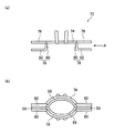
図3(a)に、長軸方向(図2中、紙面に垂直な方向、図1中、略左右方向)の充填ノズル18の縦断面図を、図3(b)に、短軸方向(図2中、左右方向)の縦断面図を、図3(c)に、図3(a)に対応する充填ノズル18の下面図を示す。なお、図3(a)〜(c)には、後述する包装袋保持装置52も併せて示してある。充填ノズル18には、中央に粉体を供給する充填口44が、長軸に沿ったその両側に粉体とともに供給された空気を排出する排気孔46が形成されている。   3A is a longitudinal sectional view of the filling nozzle 18 in the long axis direction (in FIG. 2, the direction perpendicular to the paper surface, in FIG. 1, substantially in the left-right direction), and FIG. 2 is a longitudinal sectional view in the left-right direction), and FIG. 3C is a bottom view of the filling nozzle 18 corresponding to FIG. 3A to 3C also show a packaging bag holding device 52 described later. In the filling nozzle 18, a filling port 44 for supplying powder to the center is formed, and exhaust holes 46 for discharging air supplied together with the powder are formed on both sides along the long axis.

この充填ノズル18は、円形の充填口44の口径が第2のスクリューコンベア16の外筒36の内径とほぼ同径かやや大径となる寸法で接続されており、第2のスクリューコンベア16で移送された粉体は、押し固められることなく充填ノズル18の充填口44を通過して包装袋20に充填される。このとき、粉体と同時に移送されて包装袋20の内部に流入した空気は、排気孔46から排出される。   The filling nozzle 18 is connected so that the diameter of the circular filling port 44 is approximately the same as or slightly larger than the inner diameter of the outer cylinder 36 of the second screw conveyor 16. The transferred powder passes through the filling port 44 of the filling nozzle 18 and is filled into the packaging bag 20 without being compressed. At this time, the air that is transferred simultaneously with the powder and flows into the packaging bag 20 is discharged from the exhaust hole 46.

排気孔46から排出される空気は、排気ポンプ49によって、充填口44の上部に配置された空気室48を経て、パイプ50を経由して外部に排出される。ここで、排気孔46の下面またはその内部には、空気とともに粉体が排出されるのを防止するためのフィルタ47が設けられているのが好ましい。   The air exhausted from the exhaust hole 46 is exhausted to the outside by the exhaust pump 49 through the air chamber 48 disposed above the filling port 44 and through the pipe 50. Here, it is preferable that a filter 47 for preventing the powder from being discharged together with air is provided on the lower surface of the exhaust hole 46 or inside thereof.

包装袋20は、図示しない給袋装置によって、開口部の長手方向(包装袋20の幅方向)を充填ノズル18の長軸方向に一致させて充填ノズル18の位置に供給され、充填ノズル18から下方の位置に、包装袋保持装置52によって吊り下げた状態で保持される。すなわち、充填ノズル18および包装袋保持装置52は、本発明の包装袋の装着装置を構成する。   The packaging bag 20 is supplied to the position of the filling nozzle 18 by a bag feeding device (not shown) so that the longitudinal direction of the opening (the width direction of the packaging bag 20) coincides with the long axis direction of the filling nozzle 18. The packaging bag holding device 52 is held in a state of being hung at a lower position. That is, the filling nozzle 18 and the packaging bag holding device 52 constitute the packaging bag mounting device of the present invention.

この包装袋保持装置52は、図1および図3(b)に示すように、一対の包装袋保持アーム54と、この一対の包装袋保持アーム54を開閉する保持アーム開閉機構56とからなる。包装袋保持装置52は、包装袋20の供給装置(図示しない)で充填ノズル18の位置に供給され、上端の開口部を開いて充填ノズル18に被せるように配置された包装袋20を、充填ノズル18の外周と一対の包装袋保持アーム54との間に挟持し、包装袋20を吊り下げた状態で、その開口部を充填ノズル18に密着させるように押し付けて保持する。   As shown in FIGS. 1 and 3B, the packaging bag holding device 52 includes a pair of packaging bag holding arms 54 and a holding arm opening / closing mechanism 56 that opens and closes the pair of packaging bag holding arms 54. The packaging bag holding device 52 is supplied to the position of the filling nozzle 18 by a supply device (not shown) of the packaging bag 20 and fills the packaging bag 20 arranged so as to cover the filling nozzle 18 by opening the upper end opening. While being sandwiched between the outer periphery of the nozzle 18 and the pair of packaging bag holding arms 54, the packaging bag 20 is suspended and pressed and held so as to be in close contact with the filling nozzle 18.

一対の包装袋保持アーム54のそれぞれは、図3(c)に示すように、充填ノズル18の略楕円形の外形のうち長軸で分割される半周分に対応する形状の保持部(湾曲保持部)54aを有し、一対の包装袋保持アーム54(湾曲保持部54a)で充填ノズル18を挟むことにより、充填ノズル18の全外周をほぼ閉塞する形状とされている。   As shown in FIG. 3C, each of the pair of packaging bag holding arms 54 has a holding portion (curved holding) having a shape corresponding to a half circumference divided by the major axis of the substantially elliptical outer shape of the filling nozzle 18. Portion) 54a, and the filling nozzle 18 is sandwiched between a pair of packaging bag holding arms 54 (curved holding portion 54a), so that the entire outer periphery of the filling nozzle 18 is substantially closed.

また、一対の包装袋保持アーム54のそれぞれは、湾曲保持部54aから連続して、充填ノズル18の長軸方向に延在する部分、すなわち、充填ノズル18の側方(図1および図3(c)における左右方向)に突出する直線状保持部54bを有している。一対の包装袋保持アーム54は、それぞれの湾曲保持部54aが充填ノズル18に密着する位置のとき、それぞれの直線状保持部54bが密着するように構成されている。直線状保持部54bが湾曲保持部54aの側方に突出する長さは、充填ノズル18に装着された包装袋20の開口部が充填ノズル18の側方に張り出す長さとほぼ同じか、それよりも長いことが望ましい。   Each of the pair of packaging bag holding arms 54 is a portion extending in the long axis direction of the filling nozzle 18 continuously from the curved holding portion 54a, that is, the side of the filling nozzle 18 (FIGS. 1 and 3). It has the linear holding part 54b which protrudes in the left-right direction in c). The pair of packaging bag holding arms 54 is configured such that the respective linear holding portions 54 b are in close contact with each other when the respective curved holding portions 54 a are in close contact with the filling nozzle 18. The length of the linear holding portion 54b protruding to the side of the curved holding portion 54a is substantially the same as the length of the opening of the packaging bag 20 attached to the filling nozzle 18 projecting to the side of the filling nozzle 18. Longer than that is desirable.

湾曲保持部54aおよび直線状保持部54bの包装袋20に接する面には、ゴムなどの弾性体による押圧部材58が配置されている。包装袋保持装置52は、この押圧部材58を介して包装袋20の開口部を挟持することにより、包装袋20の開口部の中央部分(充填ノズル18に接する部分)を充填ノズル18に密着させて保持するとともに、包装袋20の開口部の充填ノズル18の両側に突出する部分を一対の直線状保持部54bの間に密閉して保持する。   A pressing member 58 made of an elastic material such as rubber is disposed on the surfaces of the curved holding portion 54a and the linear holding portion 54b that are in contact with the packaging bag 20. The packaging bag holding device 52 holds the opening portion of the packaging bag 20 through the pressing member 58 so that the central portion of the opening portion of the packaging bag 20 (the portion in contact with the filling nozzle 18) is in close contact with the filling nozzle 18. And the portions projecting on both sides of the filling nozzle 18 at the opening of the packaging bag 20 are hermetically held between the pair of linear holding portions 54b.

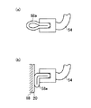
図4(a)および図4(b)は、押圧部材58の他の実施形態を示す模式的断面図である。図4(a)は、包装袋20を開放している時の状態を示し、図4(b)は包装袋20を保持している時の状態を示す。図4に示す例では、チューブ状の押圧部材58aの一部が包装袋保持アーム54の先端部に固着され、押圧部材58aの固着されていない外周面側で包装袋20が保持される。   FIG. 4A and FIG. 4B are schematic cross-sectional views showing other embodiments of the pressing member 58. 4A shows a state when the packaging bag 20 is opened, and FIG. 4B shows a state when the packaging bag 20 is held. In the example shown in FIG. 4, a part of the tube-shaped pressing member 58a is fixed to the distal end portion of the packaging bag holding arm 54, and the packaging bag 20 is held on the outer peripheral surface side where the pressing member 58a is not fixed.

また、図5(a)および図5(b)は、上述した押圧部材58の実施形態(図4に示される)とは別の実施形態を示す模式的断面図である。図5(a)は、包装袋20を開放している時の状態を示し、図5(b)は包装袋20を保持している時の状態を示す。
図5に示す例では、押圧部材58bと包装袋保持アーム54の先端とは相互に咬み合うように形成されており、押圧部材58bは包装袋保持アーム54の先端に嵌入される。押圧部材58bは、包装袋保持アーム54が包装袋20を保持する保持動作中に包装袋20の滑落を防止する滑り止めである突起部59が設けられる。
5A and 5B are schematic cross-sectional views showing an embodiment different from the above-described embodiment of the pressing member 58 (shown in FIG. 4). 5A shows a state when the packaging bag 20 is opened, and FIG. 5B shows a state when the packaging bag 20 is held.
In the example shown in FIG. 5, the pressing member 58 b and the tip of the packaging bag holding arm 54 are formed so as to bite each other, and the pressing member 58 b is fitted into the tip of the packaging bag holding arm 54. The pressing member 58 b is provided with a protrusion 59 that is a slip stopper that prevents the packaging bag 20 from slipping during the holding operation of the packaging bag holding arm 54 holding the packaging bag 20.

なお、押圧部材58としては、包装袋保持装置52による包装袋20の保持力を一層高めるために、摩擦係数の高いものや、吸着性のあるものを用いるのも好ましい。   In addition, as the pressing member 58, in order to further increase the holding force of the packaging bag 20 by the packaging bag holding device 52, it is preferable to use a member having a high friction coefficient or an adsorbing member.

なお、充填ノズル18の部分での包装袋20の密閉性をより完全にするために、ほぼ楕円形をした充填ノズル18の長軸の両端部は、包装袋保持アーム54の屈曲部(湾曲保持部54aと直線状保持部54bとの接続部)のカーブに合わせた突起形状とするのが好ましいが、押圧部材58によって包装袋20がほぼ密閉される形状であればよく、突起形状でなくともよい。また、充填ノズル18の排気孔46の形状は、上述の円形のものには限定されず、例えば、三日月形状等として、充填ノズル18の充填口44以外の面積を有効に利用し、より開孔面積を大きく取るようにしてもよい。   In order to make the sealing of the packaging bag 20 at the filling nozzle 18 more complete, both ends of the major axis of the substantially elliptical filling nozzle 18 are bent portions (curved holding of the packaging bag holding arm 54). It is preferable to have a protruding shape that matches the curve of the connecting portion between the portion 54a and the linear holding portion 54b), but any shape that allows the packaging bag 20 to be substantially sealed by the pressing member 58 is acceptable. Good. In addition, the shape of the exhaust hole 46 of the filling nozzle 18 is not limited to the circular shape described above. For example, a crescent shape or the like is used, and an area other than the filling port 44 of the filling nozzle 18 can be effectively used to open the hole. You may make it take a large area.

上述したように、包装袋20は、その幅方向が充填ノズル18の長軸方向に一致するように配置されるので、開口部はほぼ短軸の長さ分だけ開かれればよく、速やかな供給が可能である。また、包装袋保持アーム54によって、包装袋20の中央部から側部までを緩やかなカーブと直線で保持されるので、保持部における包装袋20の負担が小さい。   As described above, since the packaging bag 20 is arranged so that the width direction thereof coincides with the major axis direction of the filling nozzle 18, the opening portion only needs to be opened by the length of the minor axis, and can be quickly supplied. Is possible. Further, since the packaging bag holding arm 54 holds the packaging bag 20 from the central portion to the side portion with a gentle curve and straight line, the burden on the packaging bag 20 in the holding portion is small.

粉体充填装置10において複数種類の包装袋への充填が行われる場合には、一対の包装袋保持アーム54として、直線状保持部54bの長さが粉体充填装置10で充填される最大サイズの包装袋の開口部長さに対応するもの、すなわち、直線状保持部54bの一端から他端までの長さが、最大サイズの包装袋の開口部長さとほぼ同じかそれよりも長いものを用いることにより、包装袋保持装置52を取り替えることなく、同一の包装袋保持装置52で各種の包装袋を同様に保持することができる。   When a plurality of types of packaging bags are filled in the powder filling device 10, the length of the linear holding portion 54 b as the pair of packaging bag holding arms 54 is the maximum size to be filled in the powder filling device 10. The length corresponding to the opening length of the packaging bag, that is, the length from one end of the linear holding portion 54b to the other end is approximately the same as or longer than the opening length of the maximum size packaging bag. Thus, various packaging bags can be similarly held by the same packaging bag holding device 52 without replacing the packaging bag holding device 52.

保持アーム開閉機構56は、図1に示すように、充填ノズル18の上方に配置されたロータリーシリンダ60によって包装袋保持アーム54を揺動させるものであって、ロータリーシリンダ60を回動させることによって包装袋保持アーム54を揺動させて、包装袋20を保持し、あるいは開放する。そして、図3(b)に示すように、包装袋保持アーム54は押圧部材58を介して包装袋20の上端の開口部を充填ノズル18に密着させるように圧接して保持する。   As shown in FIG. 1, the holding arm opening / closing mechanism 56 swings the packaging bag holding arm 54 by a rotary cylinder 60 disposed above the filling nozzle 18, and rotates the rotary cylinder 60. The packaging bag holding arm 54 is swung to hold or open the packaging bag 20. Then, as shown in FIG. 3B, the packaging bag holding arm 54 is pressed and held so that the opening at the upper end of the packaging bag 20 is brought into close contact with the filling nozzle 18 via the pressing member 58.

保持アーム開閉機構56は、充填ノズル18の上方に取り付けられているので、保持アーム開閉機構56の支持部材や配線等を充填ノズル18の周辺に設ける必要が無い。そのため、充填ノズル18への包装袋20の供給路を広く確保できる。また、保持アーム開閉機構56が充填ノズル18と一体的に構成されているので、後述するように、計量装置62による粉体の充填量の測定が可能となる。   Since the holding arm opening / closing mechanism 56 is attached above the filling nozzle 18, it is not necessary to provide a support member, wiring, or the like of the holding arm opening / closing mechanism 56 around the filling nozzle 18. Therefore, a wide supply path for the packaging bag 20 to the filling nozzle 18 can be secured. In addition, since the holding arm opening / closing mechanism 56 is integrally formed with the filling nozzle 18, the powder filling amount can be measured by the weighing device 62 as will be described later.

充填ノズル18の後方(図2では右側)の位置には、収納袋20に充填された粉体の重量を計量する計量装置62が設けられている。この計量装置62は、充填ノズル18に吊り下げた状態で保持されている収納袋20に充填される粉体の重量を、充填中に即時に計測するもので、第2のスクリューコンベア16、充填ノズル18、包装袋保持装置52およびこれらに取り付けられた部品等を一体で支持することによって、それらの総重量を計測し、粉体の充填による重量の増加分を計測することで、収納袋20に充填された粉体の重量を計量する。   A measuring device 62 for measuring the weight of the powder filled in the storage bag 20 is provided at a position behind the filling nozzle 18 (on the right side in FIG. 2). This weighing device 62 measures the weight of the powder filled in the storage bag 20 held in a state suspended from the filling nozzle 18 immediately during filling. By integrally supporting the nozzle 18, the packaging bag holding device 52, and the components attached to these, the total weight thereof is measured, and the increase in weight due to powder filling is measured, whereby the storage bag 20. The weight of the powder filled in is weighed.

前述の、第1のスクリューコンベア14と第2のスクリューコンベア16との間隙に設けられたゴムなどの可撓性の弾性体からなる接続部材42は、計量装置62による充填量の計量のためにも必要であり、この接続部材42によって、第1のスクリューコンベア14が第2のスクリューコンベア16の重量を支えることがないように構成されている。このため、接続部材42は、その剛性によって計測値に誤差が生じないように、充分な可撓性を有することが必要となる。計量装置62には、従来公知の各種の計量装置を利用することができる。   The connecting member 42 made of a flexible elastic body such as rubber provided in the gap between the first screw conveyor 14 and the second screw conveyor 16 is used for measuring the filling amount by the measuring device 62. This connection member 42 is configured so that the first screw conveyor 14 does not support the weight of the second screw conveyor 16. For this reason, the connecting member 42 needs to have sufficient flexibility so that an error does not occur in the measurement value due to its rigidity. Various types of conventionally known weighing devices can be used for the weighing device 62.

充填ノズル18に吊り下げた状態で保持されている包装袋20の下方には、所定の量の粉体が充填された包装袋20を受け取る、上下動する載置台66が配置されている。この載置台66は、粉体が充填された包装袋20を衝撃なく下から受け取って包装袋20を充填部から退避させる機構を有するのが好ましい。充填ノズル18からの包装袋20への粉体の充填が完了すると、載置台66が上昇して包装袋20を支持する。次に、包装袋保持装置52による包装袋20の保持が解除される。そして、充填済みの包装袋20は、載置台66およびその他の搬送装置等によってヒートシール等の次工程へと搬送される。   Below the packaging bag 20 held in a state suspended from the filling nozzle 18, a mounting table 66 that moves up and down and receives the packaging bag 20 filled with a predetermined amount of powder is disposed. The mounting table 66 preferably has a mechanism for receiving the packaging bag 20 filled with powder from below without impact and retracting the packaging bag 20 from the filling unit. When the filling of the powder into the packaging bag 20 from the filling nozzle 18 is completed, the mounting table 66 rises and supports the packaging bag 20. Next, the holding of the packaging bag 20 by the packaging bag holding device 52 is released. Then, the filled packaging bag 20 is transported to the next process such as heat sealing by the mounting table 66 and other transport devices.

ここで、包装袋の上部を把持してこれをヒートシール等の次工程に搬送する、上記その他の搬送手段を構成する搬送用グリップによって包装袋が確実に把持されることが望ましい。以下に上記の要求をみたす形状を有する包装袋保持装置を備える粉体充填装置について説明する。   Here, it is desirable that the packaging bag is securely gripped by the grip for transport that constitutes the other transporting means that grips the upper part of the packaging bag and transports it to the next process such as heat sealing. A powder filling apparatus including a packaging bag holding apparatus having a shape that meets the above requirements will be described below.

図6は、上述した包装袋保持装置52の他の実施形態である包装袋保持装置70を備える粉体充填装置100における、包装袋保持装置70付近を示す斜視図である。ここで、以下に説明する包装袋保持装置70およびそれを備える粉体充填装置100は、図1に示される包装袋保持装置52を構成する包装袋保持アーム54を除いて同じ部品で構成される。
図6に示されるように、包装袋保持装置70は、包装袋20を保持する包装袋保持アーム72と、包装袋保持アーム72を開閉させる保持アーム開閉機構であるロータリーシリンダ60とを含み構成される。
FIG. 6 is a perspective view showing the vicinity of the packaging bag holding device 70 in the powder filling apparatus 100 including the packaging bag holding device 70 which is another embodiment of the packaging bag holding device 52 described above. Here, the packaging bag holding device 70 and the powder filling device 100 including the packaging bag holding device 70 described below are configured by the same components except for the packaging bag holding arm 54 that constitutes the packaging bag holding device 52 shown in FIG. .
As shown in FIG. 6, the packaging bag holding device 70 includes a packaging bag holding arm 72 that holds the packaging bag 20, and a rotary cylinder 60 that is a holding arm opening / closing mechanism that opens and closes the packaging bag holding arm 72. The

包装袋保持アーム72について説明する。図7(a)には包装袋保持アーム72の側面図が、図7(b)には、包装袋保持アーム72の下面図が示される。
図6または図7に示されるように、包装袋保持アーム72は、充填ノズルに沿って湾曲して形成される湾曲保持部74と、湾曲保持部74の両端から延在して充填ノズルの側方に突出する直線状保持部76と、湾曲保持部74の両端部であって直線状保持部76の下面に付設されている補助アーム78とを含み構成される。湾曲保持部74の側方に突出する直線状保持部76の長さは、充填ノズル18に装着された包装袋20の開口部が充填ノズル18の側方に張り出す長さとほぼ同じか、それよりも長いことが望ましい。
The packaging bag holding arm 72 will be described. FIG. 7A shows a side view of the packaging bag holding arm 72, and FIG. 7B shows a bottom view of the packaging bag holding arm 72.
As shown in FIG. 6 or FIG. 7, the packaging bag holding arm 72 includes a curved holding portion 74 that is curved along the filling nozzle, and a side of the filling nozzle that extends from both ends of the curved holding portion 74. A linear holding portion 76 projecting in the direction, and an auxiliary arm 78 attached to the lower surface of the linear holding portion 76 at both ends of the curved holding portion 74. The length of the linear holding part 76 protruding to the side of the curved holding part 74 is substantially the same as the length of the opening of the packaging bag 20 attached to the filling nozzle 18 projecting to the side of the filling nozzle 18, or Longer than that is desirable.

また、補助アーム78は、直線状保持部76に対して略垂直に設けられた支持部80と、支持部80から延在して直線状保持部76と略平行に設けられた当接部82とを有する。上記その他の搬送装置を構成する、後述する搬送用グリップ84が包装袋20を把持するために、直線状保持部76と当接部82とは十分な間隔を持って設けられる。また、当接部82の長さは直線状保持部76の長さと同様に、充填ノズル18に装着された包装袋20の開口部が充填ノズル18の側方に張り出す長さとほぼ同じか、それよりも長いことが望ましい。   The auxiliary arm 78 includes a support portion 80 provided substantially perpendicular to the linear holding portion 76 and a contact portion 82 extending from the support portion 80 and provided substantially parallel to the linear holding portion 76. And have. The linear holding portion 76 and the abutting portion 82 are provided with a sufficient interval so that a conveyance grip 84, which will be described later, constituting the other conveyance device grips the packaging bag 20. Further, the length of the contact portion 82 is substantially the same as the length of the opening portion of the packaging bag 20 attached to the filling nozzle 18 projecting to the side of the filling nozzle 18, similarly to the length of the linear holding portion 76. Longer than that is desirable.

図7に示されるように、包装袋保持アーム72が包装袋20に接する面には、ゴムなどの弾性体による押圧部材58が配置されている。ここで、押圧部材58には上述した押圧部材58a、58bが使用できる。   As shown in FIG. 7, a pressing member 58 made of an elastic material such as rubber is disposed on the surface where the packaging bag holding arm 72 is in contact with the packaging bag 20. Here, the pressing members 58 a and 58 b described above can be used as the pressing member 58.

ところで、包装袋20に充填される粉体は、脱気されていたり、スクリューコンベア14,16により圧縮されていたりするため、その流動性が高いものではない場合が多い。従って、補助アーム78の支持部80の内面に押圧部材58を設けなくても、包装袋保持アーム72が包装袋20を保持する保持動作中に、充填中の粉体が充填ノズル18の脇から当接部82の上方に流入するようなことは起こりにくいために、支持部80の内面には必ずしも押圧部材を設けなくてもよい。   By the way, since the powder with which the packaging bag 20 is filled is deaerated or compressed by the screw conveyors 14 and 16, the fluidity thereof is often not high. Therefore, even if the pressing member 58 is not provided on the inner surface of the support portion 80 of the auxiliary arm 78, the powder being filled from the side of the filling nozzle 18 during the holding operation in which the packaging bag holding arm 72 holds the packaging bag 20. Since it is unlikely to flow into the upper part of the contact portion 82, the pressing member is not necessarily provided on the inner surface of the support portion 80.

また、図6に示されるように保持アーム開閉機構として包装袋保持アーム72を揺動させる動力源であるロータリーシリンダ60が充填ノズル18の上部に設けられており、包装袋保持アーム72と接続されている。ロータリーシリンダ60を回動させることによって包装袋保持アーム72を揺動させて、充填ノズル18と包装袋保持アーム72との間で包装袋20を押圧することによりこれを保持することができる。   Further, as shown in FIG. 6, a rotary cylinder 60, which is a power source for swinging the packaging bag holding arm 72 as a holding arm opening / closing mechanism, is provided above the filling nozzle 18 and connected to the packaging bag holding arm 72. ing. By rotating the rotary cylinder 60, the packaging bag holding arm 72 can be swung, and the packaging bag 20 can be held by pressing between the filling nozzle 18 and the packaging bag holding arm 72.

図8は、包装袋20を保持する包装袋保持アーム72を示す正面図である。包装袋保持装置70の包装袋保持アーム72は、押圧部材58を介して包装袋20の開口部を保持することにより、包装袋20の開口部の中央部分(充填ノズル18に接する部分)を充填ノズル18に密着させて保持するとともに、包装袋20の開口部の充填ノズル18の両側に突出する部分を一対の直線状保持部76で保持することにより包装袋20を密閉する。   FIG. 8 is a front view showing the packaging bag holding arm 72 that holds the packaging bag 20. The packaging bag holding arm 72 of the packaging bag holding device 70 fills the central portion of the opening of the packaging bag 20 (the portion in contact with the filling nozzle 18) by holding the opening of the packaging bag 20 via the pressing member 58. The packaging bag 20 is hermetically sealed by being held in close contact with the nozzle 18 and holding a portion of the opening of the packaging bag 20 that protrudes on both sides of the filling nozzle 18 with a pair of linear holding portions 76.

また、補助アーム78は、包装袋20を挟持することによって、包装袋20内部に充填される粉体が包装袋20上部へ流入することを防ぐことができる。これにより、図8に破線で示されるように、包装袋20を次工程へと搬送するその他の搬送手段の搬送用グリップ84が包装袋20を把持するためのスペースを確保することができる。粉体が包装袋20上部に流入して搬送用グリップ84の把持動作を妨げることがないので、安定した充填が可能である。また、包装袋20をシールするためのシール代を確保することができる。   Further, the auxiliary arm 78 can prevent the powder filled in the packaging bag 20 from flowing into the upper portion of the packaging bag 20 by sandwiching the packaging bag 20. Thereby, as shown by a broken line in FIG. 8, a space for holding the packaging bag 20 by the conveyance grip 84 of other conveyance means for conveying the packaging bag 20 to the next process can be secured. Since the powder does not flow into the upper part of the packaging bag 20 and hinder the gripping operation of the conveyance grip 84, stable filling is possible. Moreover, the sealing allowance for sealing the packaging bag 20 is securable.

さらに、補助アーム78を設けた結果、包装袋20の大きさを従来よりも小さくすることができる。従来、搬送用グリップ84が包装袋20における粉体が充填されない領域を確実に把持するために、包装袋20の上部に余裕をもたせていた。しかし、補助アーム78によって包装袋20における粉体が充填される領域が限定されるために、包装袋20にそのような余裕を持たせる必要がなく、包装袋20を小さくすることが可能になる。これにより、包装袋20の製造に要する包装材料の使用量が減少しコストを削減することができる。   Furthermore, as a result of providing the auxiliary arm 78, the size of the packaging bag 20 can be made smaller than before. Conventionally, in order for the conveyance grip 84 to securely hold a region of the packaging bag 20 that is not filled with powder, a margin is provided on the upper portion of the packaging bag 20. However, since the area where the powder in the packaging bag 20 is filled by the auxiliary arm 78 is limited, it is not necessary to allow the packaging bag 20 to have such a margin, and the packaging bag 20 can be made smaller. . Thereby, the usage-amount of the packaging material required for manufacture of the packaging bag 20 reduces, and it can reduce cost.

また、同時に粉体の嵩密度を高くすることができ、これにより充填および包装が完了した包装袋20のはい付け作業時における包装袋20を積み上げた状態での安定性が良好になる。   At the same time, the bulk density of the powder can be increased, thereby improving the stability of the packaging bag 20 in the state where the packaging bag 20 is filled and packed in the attaching operation.

図8に示される搬送用グリップ84は、充填が完了した包装袋20をヒートシール工程や、整形工程といった次工程に搬送する公知の搬送装置の搬送用グリップである。搬送用グリップ84は、包装袋20が粉体充填装置100(図6参照)に供給されて粉体の充填が完了するまでの間、充填作業を妨げない位置に退避している。充填が完了した後、搬送用グリップ84が、包装袋保持アーム72の直線状保持部76と当接部82との間を把持し、上述したような次工程に包装袋20を搬送する。   The conveyance grip 84 shown in FIG. 8 is a conveyance grip of a known conveyance device that conveys the filled packaging bag 20 to the next process such as a heat sealing process or a shaping process. The conveyance grip 84 is retracted to a position where the filling operation is not hindered until the packaging bag 20 is supplied to the powder filling device 100 (see FIG. 6) and the filling of the powder is completed. After the filling is completed, the conveyance grip 84 grips between the linear holding portion 76 and the contact portion 82 of the packaging bag holding arm 72, and conveys the packaging bag 20 to the next process as described above.

ところで、上述した包装袋保持アーム72に含まれる補助アーム78は、直線状保持部76と湾曲保持部74との接続部に溶接等の手段で一体的に構成されているものであるが、使用中における変形等を考慮すると、補助アーム78の角度変更等の調整が容易に行えることも好ましい。以下に、このような補助アームの角度を調節するための接続部材を介して接続された補助アームを備える包装袋保持アームの実施形態について説明する。   By the way, the auxiliary arm 78 included in the packaging bag holding arm 72 described above is configured integrally with a connecting portion between the linear holding portion 76 and the curved holding portion 74 by means such as welding. In consideration of deformation in the inside, it is also preferable that adjustment such as an angle change of the auxiliary arm 78 can be easily performed. Below, embodiment of a packaging bag holding arm provided with the auxiliary arm connected via the connection member for adjusting the angle of such an auxiliary arm is described.

図9は、図7の矢印Aに示される方向から包装袋保持アームを見たときに相当する包装袋保持アーム90を示す側面図である。包装袋保持アーム90は、補助アームを接続する接続部材92を有することと、図7に示される包装袋保持アーム72における補助アーム78に相当する補助アーム94を有すること以外は、上述した包装袋保持アーム72と同様の構成である。   FIG. 9 is a side view showing the packaging bag holding arm 90 corresponding to the packaging bag holding arm 90 when viewed from the direction indicated by the arrow A in FIG. The packaging bag holding arm 90 has the connecting member 92 for connecting the auxiliary arm, and the packaging bag described above except that it has the auxiliary arm 94 corresponding to the auxiliary arm 78 in the packaging bag holding arm 72 shown in FIG. The configuration is the same as that of the holding arm 72.

図9に示される接続部材92は、湾曲保持部74の近傍で直線状保持部76の下側面に位置決め固定される板状の部材である。接続部材92の側面には、補助アーム94をボルト98で固定するための穴が設けられている。また、補助アーム94を構成する、略垂直方向に設けられた支持部96の上部にも、支持部96を接続部材92にボルト98で固定するための穴が設けられている。これらの穴は、直線状保持部76の長手方向と平行(図9では紙面に対して垂直)になるように設けられる。補助アーム94は接続部材92にボルト98を締結して固定される際に、その固定された点を軸に回動させることによりその角度の調節がなされる。   The connection member 92 shown in FIG. 9 is a plate-like member that is positioned and fixed on the lower surface of the linear holding portion 76 in the vicinity of the curved holding portion 74. A hole for fixing the auxiliary arm 94 with a bolt 98 is provided on the side surface of the connection member 92. In addition, a hole for fixing the support portion 96 to the connection member 92 with a bolt 98 is also provided in the upper portion of the support portion 96 provided in the substantially vertical direction that constitutes the auxiliary arm 94. These holes are provided so as to be parallel to the longitudinal direction of the linear holding portion 76 (perpendicular to the paper surface in FIG. 9). When the auxiliary arm 94 is fixed by fastening the bolt 98 to the connecting member 92, the angle of the auxiliary arm 94 is adjusted by rotating the fixed point about the axis.

上述のようにして角度が調節できることによって、例えば、包装袋保持アーム90の保持動作中に、一対の補助アーム94が十分な挟持力で包装袋を挟持できない場合は、補助アーム94の角度を調節して、補助アーム94が包装袋に当接する方向にその位置を移動させることで問題を解決することができる。   By adjusting the angle as described above, for example, when the pair of auxiliary arms 94 cannot hold the packaging bag with sufficient holding force during the holding operation of the packaging bag holding arm 90, the angle of the auxiliary arm 94 is adjusted. Then, the problem can be solved by moving the position of the auxiliary arm 94 in the direction in which the auxiliary arm 94 comes into contact with the packaging bag.

また、補助アーム94が包装袋を挟持する挟持動作が包装袋保持アーム90の保持動作を妨げて、包装袋保持アーム90が十分な保持力で包装袋を保持できない場合は、補助アーム94が包装袋に当接する方向と逆の方向に補助アーム94の位置を移動させることで問題を解決することができる。   Further, when the auxiliary arm 94 holds the packaging bag and the holding operation of the packaging bag holding arm 90 is hindered, and the packaging bag holding arm 90 cannot hold the packaging bag with a sufficient holding force, the auxiliary arm 94 performs the packaging. The problem can be solved by moving the position of the auxiliary arm 94 in the direction opposite to the direction in contact with the bag.

また、本実施形態の包装袋保持アーム90は、二対の補助アーム94相互間の距離を調節可能に構成されるため、様々な形状(厚み)の包装袋を使用する場合等にも対応できる。   In addition, since the packaging bag holding arm 90 of the present embodiment is configured so that the distance between the two pairs of auxiliary arms 94 can be adjusted, the packaging bag holding arm 90 can also be used when packaging bags of various shapes (thicknesses) are used. .

本発明の包装袋の装着装置は、以上に説明したように構成されているので、上端辺が開放された開口部を有する包装袋を用い、この包装袋に粉体を高速かつ高精度で充填できる粉体充填装置において、包装袋の開口部からの粉体の飛散を防ぐことができ、かつ包装袋を確実に保持でき、さらには、異なるサイズの包装袋にも対応できる包装袋の装着装置を提供することができる。   Since the packaging bag mounting device of the present invention is configured as described above, a packaging bag having an opening having an open upper end is used, and powder is filled in the packaging bag at high speed and with high accuracy. In a powder filling apparatus capable of preventing powder scattering from the opening of the packaging bag, holding the packaging bag securely, and further supporting packaging bags of different sizes Can be provided.

また、包装袋を次工程に搬送する公知の搬送装置が確実に包装袋を把持するためのスペースを確保することができ、それと同時に、包装袋の上部をシールするシール代も確保できる。さらに、包装袋を小型化することによりコストを削減することができる。また、包装袋を小型化した結果として嵩密度を高くすることもできる。   In addition, a known conveyance device for conveying the packaging bag to the next process can secure a space for securely holding the packaging bag, and at the same time, a seal margin for sealing the upper portion of the packaging bag can be secured. Furthermore, the cost can be reduced by downsizing the packaging bag. In addition, the bulk density can be increased as a result of downsizing the packaging bag.

以上、本発明の包装袋の装着装置について詳細に説明したが、上述の構成に限定されずにその趣旨を逸脱しない範囲において変更が可能である。   As mentioned above, although the mounting apparatus of the packaging bag of this invention was demonstrated in detail, it can change in the range which does not deviate from the meaning, without being limited to the above-mentioned structure.

本発明の包装袋の装着装置を採用した粉体充填装置の一例を示す斜視図である。It is a perspective view which shows an example of the powder filling apparatus which employ | adopted the mounting apparatus of the packaging bag of this invention. 図1の粉体充填装置の断面図である。It is sectional drawing of the powder filling apparatus of FIG. 充填ノズルの形状を示すものであって、(a)は、充填ノズルの長軸方向の縦断面図、(b)は、充填ノズルの短軸方向の縦断面図、(c)は、(a)に対応する充填ノズルの下面図である。The shape of the filling nozzle is shown, wherein (a) is a longitudinal sectional view of the filling nozzle in the major axis direction, (b) is a longitudinal sectional view of the filling nozzle in the minor axis direction, and (c) is (a) It is a bottom view of the filling nozzle corresponding to). 押圧部材58の他の実施形態を示す模式的断面図であり、(a)は、包装袋20を開放している時の状態を示し、(b)は包装袋20を保持している時の状態を示す。It is typical sectional drawing which shows other embodiment of the press member 58, (a) shows the state when the packaging bag 20 is open | released, (b) is when the packaging bag 20 is hold | maintained. Indicates the state. 押圧部材58の他の実施形態である押圧部材58bを示す模式的断面図であり、(a)は、包装袋20を開放している時の状態を示し、(b)は包装袋20を保持している時の状態を示す。It is typical sectional drawing which shows the press member 58b which is other embodiment of the press member 58, (a) shows the state when the packaging bag 20 is open | released, (b) hold | maintains the packaging bag 20. Indicates the state when 包装袋保持装置70付近の要部を示す斜視図である。It is a perspective view which shows the principal part of packaging bag holding | maintenance apparatus 70 vicinity. 包装袋保持アーム72を示し(a)には側面図を、(b)には下面図を示す。The packaging bag holding arm 72 is shown, (a) is a side view, and (b) is a bottom view. 包装袋20を保持する包装袋保持アーム72を示す正面図である。FIG. 6 is a front view showing a packaging bag holding arm 72 that holds the packaging bag 20. 包装袋保持アーム90を示す側面図である。It is a side view which shows the packaging bag holding | maintenance arm 90. FIG. 従来技術の粉体充填装置を示す断面図である。It is sectional drawing which shows the powder filling apparatus of a prior art.

符号の説明Explanation of symbols

10 粉体充填装置
12 ホッパー
14 第1のスクリューコンベア
16 第2のスクリューコンベア
18 充填ノズル
20 包装袋
22 攪拌装置
24 軸
26 棒状の突起
28 モータ
30,36 外筒
32,38 スクリュー
34,40 モータ
42 接続部材
44 充填口
46 排気孔
47 フィルタ
48 空気室
49 排気ポンプ
50 パイプ
52 包装袋保持装置
54 包装袋保持アーム
54a 湾曲保持部
54b 直線状保持部
56 保持アーム開閉機構
58,58a,58b 押圧部材
59 突起部
60 ロータリーシリンダ
62 計量装置
66 載置台
70 包装袋保持装置
72 包装袋保持アーム
74 湾曲保持部
76 直線状保持部
78 補助アーム
80 支持部
82 当接部
84 搬送用グリップ
90 包装袋保持アーム
92 接続部材
94 補助アーム
96 支持部
98 ボルト
100 粉体充填装置
120,122,124 脱気口
120a,122a,124a フィルタ
120b,122b,124b 脱気管
DESCRIPTION OF SYMBOLS 10 Powder filling device 12 Hopper 14 1st screw conveyor 16 2nd screw conveyor 18 Filling nozzle 20 Packaging bag 22 Stirrer 24 Shaft 26 Rod-shaped protrusion 28 Motor 30, 36 Outer cylinder 32, 38 Screw 34, 40 Motor 42 Connecting member 44 Filling port 46 Exhaust hole 47 Filter 48 Air chamber 49 Exhaust pump 50 Pipe 52 Packaging bag holding device 54 Packaging bag holding arm 54a Curved holding part 54b Linear holding part 56 Holding arm opening / closing mechanism 58, 58a, 58b Pressing member 59 Protrusion 60 Rotary cylinder 62 Weighing device 66 Mounting table 70 Packaging bag holding device 72 Packaging bag holding arm 74 Curved holding portion 76 Linear holding portion 78 Auxiliary arm 80 Supporting portion 82 Contacting portion 84 Carrying grip 90 Packaging bag holding arm 92 Connecting member 94 Arm 96 supporting portion 98 bolt 100 powder filling apparatus 120, 122, 124 deaeration port 120a, 122a, 124a filters 120b, 122b, 124b deaerating tube

Claims (9)

粉体を供給して包装袋に充填する充填口および前記粉体と同時に供給される空気を前記包装袋から排出する排気孔を有する充填ノズルと、
中央部が前記充填ノズルの外周にほぼ密着する形状(湾曲部)であって、両端部が前記充填ノズルの外方に突出する形状である一対の包装袋保持アームと、
前記一対の包装袋保持アームを開閉する保持アーム開閉機構とを有し、
前記粉体を充填する前記包装袋を、前記充填ノズルの外周と前記一対の包装袋保持アームとの間に挟持して保持することを特徴とする包装袋の装着装置。
A filling nozzle for supplying powder to fill the packaging bag and a filling nozzle having an exhaust hole for discharging air supplied simultaneously with the powder from the packaging bag;
A pair of packaging bag holding arms having a shape (curved portion) in which the central portion is substantially in close contact with the outer periphery of the filling nozzle, and both end portions are shaped to protrude outward of the filling nozzle;
A holding arm opening and closing mechanism for opening and closing the pair of packaging bag holding arms,
The packaging bag mounting device, wherein the packaging bag for filling the powder is sandwiched and held between an outer periphery of the filling nozzle and the pair of packaging bag holding arms.
前記充填ノズルは、断面形状がほぼ楕円形であって、中央部に円形の前記充填口を有し、その両側に前記排気孔が配置されていることを特徴とする請求項1に記載の包装袋の装着装置。   The packaging according to claim 1, wherein the filling nozzle has a substantially elliptical cross-sectional shape, has a circular filling port in the center, and the exhaust holes are arranged on both sides thereof. Bag mounting device. 前記包装袋保持アームは、前記充填ノズルに当接する前記包装袋保持アームの湾曲部の近傍の下面に付設された、前記包装袋を挟持して前記包装袋における前記粉体が充填される領域を制限する補助アームを含み、
前記補助アームの一部が、前記包装袋保持アームと平行になるように設けられていることを特徴とする請求項1または2に記載の包装袋の装着装置。
The packaging bag holding arm is attached to a lower surface in the vicinity of the curved portion of the packaging bag holding arm in contact with the filling nozzle, and sandwiches the packaging bag and fills the powder in the packaging bag. Including auxiliary arms to limit,
The packaging bag mounting device according to claim 1, wherein a part of the auxiliary arm is provided in parallel with the packaging bag holding arm.
前記一対の包装袋保持アームおよび/または前記補助アームの内面には、前記包装袋を前記充填ノズルの外周に圧接する弾性体による押圧部材を有することを特徴とする請求項1〜3のいずれかに記載の包装袋の装着装置。   4. A pressing member made of an elastic body that presses the packaging bag against the outer periphery of the filling nozzle is provided on the inner surface of the pair of packaging bag holding arms and / or the auxiliary arm. The packaging bag mounting device described in 1. 前記押圧部材は、その外周面で前記包装袋を保持するチューブ状の弾性体であることを特徴とする請求項4に記載の包装袋の装着装置。   The packaging bag mounting device according to claim 4, wherein the pressing member is a tubular elastic body that holds the packaging bag on an outer peripheral surface thereof. 前記押圧部材は、その外周面で前記包装袋を保持するための滑り止めとしての突起部を有する弾性体であることを特徴とする請求項4に記載の包装袋の装着装置。   The packaging bag mounting device according to claim 4, wherein the pressing member is an elastic body having a protrusion as a slip stopper for holding the packaging bag on an outer peripheral surface thereof. 前記一対の包装袋保持アームにおける前記充填ノズルの外方に突出する部分の長さは、前記充填ノズルに装着された前記包装袋の開口部の前記充填ノズルから突出する長さ以上であることを特徴とする請求項1〜6のいずれかに記載の包装袋の装着装置。   The length of the portion protruding outward of the filling nozzle in the pair of packaging bag holding arms is equal to or longer than the length protruding from the filling nozzle of the opening of the packaging bag attached to the filling nozzle. The packaging bag mounting device according to any one of claims 1 to 6. 前記一対の包装袋保持アームを開閉する前記保持アーム開閉機構が、前記充填ノズルの上側に配置されていることを特徴とする請求項1〜7のいずれかに記載の包装袋の装着装置。   The packaging bag mounting device according to any one of claims 1 to 7, wherein the holding arm opening and closing mechanism for opening and closing the pair of packaging bag holding arms is disposed above the filling nozzle. 前記充填ノズルの前記排気孔には、空気とともに粉体が排出されることを防止するフィルタと、このフィルタを通して排出される空気を吸引する排気ポンプとを有することを特徴とする請求項1〜8のいずれかに記載の包装袋の装着装置。   9. The exhaust hole of the filling nozzle has a filter for preventing powder from being discharged together with air, and an exhaust pump for sucking air discharged through the filter. The packaging bag mounting device according to any one of the above.
JP2004365801A 2004-04-07 2004-12-17 Packaging-bag loading device Pending JP2005320066A (en)

Priority Applications (1)

Application Number Priority Date Filing Date Title
JP2004365801A JP2005320066A (en) 2004-04-07 2004-12-17 Packaging-bag loading device

Applications Claiming Priority (2)

Application Number Priority Date Filing Date Title
JP2004112736 2004-04-07
JP2004365801A JP2005320066A (en) 2004-04-07 2004-12-17 Packaging-bag loading device

Publications (2)

Publication Number Publication Date
JP2005320066A true JP2005320066A (en) 2005-11-17
JP2005320066A5 JP2005320066A5 (en) 2007-09-06

Family

ID=35467624

Family Applications (1)

Application Number Title Priority Date Filing Date
JP2004365801A Pending JP2005320066A (en) 2004-04-07 2004-12-17 Packaging-bag loading device

Country Status (1)

Country Link
JP (1) JP2005320066A (en)

Cited By (4)

* Cited by examiner, † Cited by third party
Publication number Priority date Publication date Assignee Title
JP2007302279A (en) * 2006-05-10 2007-11-22 Nisshin Seifun Group Inc Powder filling device
JP4880000B2 (en) * 2006-02-10 2012-02-22 エコ、レーン、リサーチ、アンド、デベロップメント、アクティーゼルスカブ Folding container filling device
CN107719764A (en) * 2017-11-20 2018-02-23 咸丰隆态生物科技有限公司 A kind of biomass fertilizers sack-filling device
CN107985679A (en) * 2017-11-24 2018-05-04 重庆六丰农业开发有限公司 A kind of rice packaging device

Cited By (4)

* Cited by examiner, † Cited by third party
Publication number Priority date Publication date Assignee Title
JP4880000B2 (en) * 2006-02-10 2012-02-22 エコ、レーン、リサーチ、アンド、デベロップメント、アクティーゼルスカブ Folding container filling device
JP2007302279A (en) * 2006-05-10 2007-11-22 Nisshin Seifun Group Inc Powder filling device
CN107719764A (en) * 2017-11-20 2018-02-23 咸丰隆态生物科技有限公司 A kind of biomass fertilizers sack-filling device
CN107985679A (en) * 2017-11-24 2018-05-04 重庆六丰农业开发有限公司 A kind of rice packaging device

Similar Documents

Publication Publication Date Title
ES2311237T3 (en) MACHINE TO CONFORM, FILL AND CLOSE SACKS WITH SACK ELEVATOR DEVICE.
JP4402967B2 (en) Powder filling equipment
JP2005008282A (en) Feeder of powder
CN209410378U (en) A kind of automatic packaging machine of particulate species material
JP2005320066A (en) Packaging-bag loading device
US20160368719A1 (en) Emptying device
JP2005164569A (en) Vacuum conveying apparatus equipped with weighing device
JP2005502560A (en) Apparatus and method for transporting material transported in the form of fine particles, powder, granules or granules from a storage container into a work container or transport container, or an equivalent storage space
JP2007302279A (en) Powder filling device
JP2019081552A (en) Packaging machine and packaging method
JPH06298363A (en) Pneumatic transport device for power/grain material
JP4427432B2 (en) Powder filling method
ITMI20072177A1 (en) PACKAGING MACHINE FOR PACKAGING FINE GRAIN PRODUCTS
ES2939038T3 (en) Flow regulation system for filling a bag with a granular product, and corresponding machine and procedure
JP2005297976A (en) Device for vertically moving packaging bag loading table, and packaging bag carrying-out device
JP7072185B2 (en) Granular material supply device
CN211545262U (en) Powder worm charge device
CN215972213U (en) Vibration type is weighed down and is removed ton chartered plane
CN211001953U (en) Micro powder packaging machine
JP4069234B2 (en) Method for filling powder into container
CN213974544U (en) Quantitative packaging system for powdery materials
CN214652120U (en) Powder charge vibration unloading module
CN218839830U (en) Granular material ton bag packaging machine
CN216762440U (en) Material conveying structure and equipment under differential pressure condition
CN214277162U (en) Dry powder weighing device

Legal Events

Date Code Title Description
A521 Written amendment

Effective date: 20070724

Free format text: JAPANESE INTERMEDIATE CODE: A523

A621 Written request for application examination

Free format text: JAPANESE INTERMEDIATE CODE: A621

Effective date: 20070724

A977 Report on retrieval

Free format text: JAPANESE INTERMEDIATE CODE: A971007

Effective date: 20091022

A131 Notification of reasons for refusal

Free format text: JAPANESE INTERMEDIATE CODE: A131

Effective date: 20091027

A02 Decision of refusal

Free format text: JAPANESE INTERMEDIATE CODE: A02

Effective date: 20100309