JP4401507B2 - Active pixel sensor with wired floating diffusion and common amplifier - Google Patents
Active pixel sensor with wired floating diffusion and common amplifier Download PDFInfo
- Publication number
- JP4401507B2 JP4401507B2 JP37399899A JP37399899A JP4401507B2 JP 4401507 B2 JP4401507 B2 JP 4401507B2 JP 37399899 A JP37399899 A JP 37399899A JP 37399899 A JP37399899 A JP 37399899A JP 4401507 B2 JP4401507 B2 JP 4401507B2
- Authority
- JP
- Japan
- Prior art keywords
- pixel
- pixels
- charge
- floating diffusion
- voltage conversion
- Prior art date
- Legal status (The legal status is an assumption and is not a legal conclusion. Google has not performed a legal analysis and makes no representation as to the accuracy of the status listed.)
- Expired - Lifetime
Links
- 238000009792 diffusion process Methods 0.000 title description 53
- 238000006243 chemical reaction Methods 0.000 claims description 21
- 239000004065 semiconductor Substances 0.000 claims description 3
- 239000000758 substrate Substances 0.000 claims description 3
- 241000086550 Dinosauria Species 0.000 description 4
- 238000001444 catalytic combustion detection Methods 0.000 description 4
- 230000002596 correlated effect Effects 0.000 description 3
- 238000005070 sampling Methods 0.000 description 3
- 230000002411 adverse Effects 0.000 description 2
- 230000000694 effects Effects 0.000 description 2
- 239000002184 metal Substances 0.000 description 2
- 230000000116 mitigating effect Effects 0.000 description 2
- 230000000875 corresponding effect Effects 0.000 description 1
- 230000003247 decreasing effect Effects 0.000 description 1
- 239000011159 matrix material Substances 0.000 description 1
- 230000003287 optical effect Effects 0.000 description 1
- 238000012856 packing Methods 0.000 description 1
- 230000035945 sensitivity Effects 0.000 description 1
- 239000007787 solid Substances 0.000 description 1
Images


Classifications
-
- H—ELECTRICITY
- H01—ELECTRIC ELEMENTS
- H01L—SEMICONDUCTOR DEVICES NOT COVERED BY CLASS H10
- H01L27/00—Devices consisting of a plurality of semiconductor or other solid-state components formed in or on a common substrate
- H01L27/14—Devices consisting of a plurality of semiconductor or other solid-state components formed in or on a common substrate including semiconductor components sensitive to infrared radiation, light, electromagnetic radiation of shorter wavelength or corpuscular radiation and specially adapted either for the conversion of the energy of such radiation into electrical energy or for the control of electrical energy by such radiation
- H01L27/144—Devices controlled by radiation
- H01L27/146—Imager structures
- H01L27/14601—Structural or functional details thereof
- H01L27/14603—Special geometry or disposition of pixel-elements, address-lines or gate-electrodes
-
- H—ELECTRICITY
- H01—ELECTRIC ELEMENTS
- H01L—SEMICONDUCTOR DEVICES NOT COVERED BY CLASS H10
- H01L27/00—Devices consisting of a plurality of semiconductor or other solid-state components formed in or on a common substrate
- H01L27/14—Devices consisting of a plurality of semiconductor or other solid-state components formed in or on a common substrate including semiconductor components sensitive to infrared radiation, light, electromagnetic radiation of shorter wavelength or corpuscular radiation and specially adapted either for the conversion of the energy of such radiation into electrical energy or for the control of electrical energy by such radiation
- H01L27/144—Devices controlled by radiation
- H01L27/146—Imager structures
- H01L27/14601—Structural or functional details thereof
- H01L27/14609—Pixel-elements with integrated switching, control, storage or amplification elements
-
- H—ELECTRICITY
- H01—ELECTRIC ELEMENTS
- H01L—SEMICONDUCTOR DEVICES NOT COVERED BY CLASS H10
- H01L27/00—Devices consisting of a plurality of semiconductor or other solid-state components formed in or on a common substrate
- H01L27/14—Devices consisting of a plurality of semiconductor or other solid-state components formed in or on a common substrate including semiconductor components sensitive to infrared radiation, light, electromagnetic radiation of shorter wavelength or corpuscular radiation and specially adapted either for the conversion of the energy of such radiation into electrical energy or for the control of electrical energy by such radiation
- H01L27/144—Devices controlled by radiation
- H01L27/146—Imager structures
- H01L27/14601—Structural or functional details thereof
- H01L27/14641—Electronic components shared by two or more pixel-elements, e.g. one amplifier shared by two pixel elements
-
- H—ELECTRICITY
- H04—ELECTRIC COMMUNICATION TECHNIQUE
- H04N—PICTORIAL COMMUNICATION, e.g. TELEVISION
- H04N3/00—Scanning details of television systems; Combination thereof with generation of supply voltages
- H04N3/10—Scanning details of television systems; Combination thereof with generation of supply voltages by means not exclusively optical-mechanical
- H04N3/14—Scanning details of television systems; Combination thereof with generation of supply voltages by means not exclusively optical-mechanical by means of electrically scanned solid-state devices
- H04N3/15—Scanning details of television systems; Combination thereof with generation of supply voltages by means not exclusively optical-mechanical by means of electrically scanned solid-state devices for picture signal generation
- H04N3/155—Control of the image-sensor operation, e.g. image processing within the image-sensor
Description
【0001】
【発明の属する技術分野】
本発明は固体フォトセンサと、各ピクセルと関連したアクティブ回路素子を有するアクティブピクセルセンサ(APS)と呼ばれるイメージャとの分野に関し、より詳細には、光検出器から分離された電荷- 電圧変換領域のあるピクセルの4つのトランジスターピクセルと、相関二重サンプリング(correlated double sampling、CDS)とを利用する固体イメージャに関する。
【0002】
【従来の技術】
APSは固体イメージャであり、各ピクセルは光感知手段と、リセット手段と、電荷- 電圧変換手段と、行選択手段と、さらに全て又は部分的に増幅器とを具備する固体ピクセル素子を通常含む。ピクセル内に集められた光電荷は、エリック フォサム(Eric Fossum) による1993年7月のSPIEの1900-08-8194-1133 巻での「アクティブピクセルセンサ:CCDは恐竜か?(Active Pixel Sensors: Are CCD's Dinosaurs?) 」等の先行技術文献で説明されているように、ピクセル内で対応する電圧若しくは電流に変換される。APSデバイスは、イ フォサム(E. Fossum) による1993年7月のSPIEの1900-08-8194-1133 巻での「アクティブピクセルセンサ:CCDは恐竜か?(Active Pixel Sensors: Are CCD's Dinosaurs?) 」や、R. H. Nixon, S. E. Kemeny、C. O. Staller とE. R. FossumによるSPIEのプロシーディング2415巻の「オンチップタイミングと、コントロールと信号チェーン電子工学とを有する128x128CMOSフォトダイオードタイプアクティブマトリックスセンサ(128x128 CMOS Photodiode-type Active Pixel Sensor with On-chip Timing, Controland Signal Chain Electronics) 」、1995年の論文34での「電荷結合素子と固体光学センサV(Charge-Coupled Devices and Solid-State Optical Sensors V) 」で説明されているように、イメージャの各ライン又は行が選択されてから、列選択信号を利用して読出されるように作動されてきた。アクティブピクセルセンサ内での行及び列の選択は、メモリ装置でのワード及びビットの選択に類似する。ここで、全体の行の選択はワードを選択することに類似しており、アクティブピクセルセンサの一つの列からの読出しは、そのワード内で単一のビットラインを選択又はイネーブリングすることに類似する。従来の先行技術でのアクティブピクセルセンサ装置では、4つのトランジスター設計を利用するアーキテクチャを示しており、全ての4つのトランジスターは夫々及びいずかのピクセル内に含まれている。4つのトランジスターは、通常、トランスファー、行選択、リセット及びソースフォロワ増幅器トランジスターである。このアーキテクチャは容易にCDSを実行し、低読出しノイズが得られる能力を有するAPSが得られる利点があるが、上記4Tピクセルは低い充填比(fill factor)である。充填比は光センサに当てるピクセル面積の割合である。上記4つのトランジスターと関連するコンタクト領域と信号バスは各ピクセルに配置され、コンタクト領域は所望の重なりとさまざまな層の空間により、通常大きなピクセル面積を使うので、ピクセルの充填比はさもなければ光検出器に利用されるであろう大きな面積が使用されるため減少する。上記部品の夫々の適当なタイミング信号への接続は、ピクセルの全体の行を横行する金属バスにより行われる。上記金属バスは光学的に不透明であり、光検出器の領域をさえぎり、ピクセルピッチに適合する。更に、このことはピクセルの充填比を減少させる。充填比を減少させることは、センサの感度及び飽和信号を低下させる。上記のことはセンサの写真スピードやダイナミックレンジ、さらに高画質を得るために重要である性能指標に悪影響を与える。
【0003】
米国特許第6160281号及び6107655号明細書において、Guidash は、フローティングディフュージョン、行選択トランジスター、リセットトランジスター及びソースフォロワ入力トランジスターを隣接行のピクセル間で共有することにより、先行技術での4つのトランジスターピクセルの機能性を維持するピクセルアーキテクチャを開示している。上記アーキテクチャでは、単一のフローティングディフュージョン領域は、2又は4つの隣接ピクセル間で共有される。上記アーキテクチャは高い充填比を提供するが、物理的に大きなフローティングディフュージョン領域を生じさせる。このことは、電荷- 電圧変換ノードの全静電容量の大部分であるフローティングディフュージョンの電圧に依存する接合静電容量により、一層非線形な電荷- 電圧変換が生じる。更に、各ピクセル内の光検出器の同じ配置を維持しようとすると、フローティングディフュージョンとリセットトランジスターの非効率なレイアウトが招来する。非線形電荷- 電圧変換は可変なカラーバランスのアーティファクトをもたらす。各ピクセル内の光検出器の同じでない配置により、別のアーティファクトが生じる。上記アーティファクトの双方とも画質に悪影響をもたらす。
【0004】
典型的な先行技術でのフォトダイオードAPSピクセルを図1に示す。図1に示すピクセルは、フォトダイオード(PD)、トランスファートランジスター(TG)、フローティングディフュージョン(FD)、リセットゲート(RG)のあるリセットトランジスターと、行選択ゲート(RSG)のある行選択トランジスターと、ソースフォロワ入力信号トランジスター(SIG)とからなる先行技術での4つのトランジスターピクセルである。上記先行技術でのピクセルの充填比は通常25%以下である。
【0005】
Guidash により提案された別のピクセルアーキテクチャを、図2及び図3に示す。図2では、2つの行隣接ピクセル、ピクセルA及びピクセルBは、分離フォトダイオードとトランスファーゲート、PDa、PDb、TGa、TGbを夫々有するが、他の全ての構成部品、FD、RG、RSG及びSIGを共有する。図3では、1及び2は行を、a及びbは列を夫々表わし、4つの行及び列隣接ピクセル、ピクセル1a、2a、1b及び2bは分離PD’sとTG’s、PD1a、PD2a、PD1b、PD2b、TG1a、TG2a及びTG2bを有するが、他の全ての構成部品FD、RG、RSG及びSIGを共有する。この場合、行ごとに2つのトランスファーゲートバスがあり、隣接列からの信号電荷の混合を防止している。上記アーキテクチャは、図1に示す先行技術でのピクセルよりは実質的に高い充填比を、つまり小さなピクセルを提供するが、前述したように、数多の欠点がある。図2に示す2つの隣接ピクセル又は図3に示す4つの隣接ピクセルのいずれかにより共有される単一のフローティングディフュージョン領域を有することにより、図1で得られるよりは物理的に大きなフローティングディフュージョンが生じることが分かる。更に、図2及び図3から、隣接ピクセル境界内での光検出器の配置は同じでないことは明らかである。
【0006】
高い充填比を有する別のピクセルアーキテクチャと、Guidash により提案された共有増幅器ピクセルの能力のように、CDSを実行できる能力と、更に各ピクセル内の光検出器の同じ配置で、より線形である電荷- 電圧変換を有するセンサが望まれている。
【0007】
【発明が解決しようとする課題】
本発明は上述の点に鑑みてなされたものであり、相関二重サンプリング(CDS)を実行する能力のある高い充填比のアクティブピクセルアーキテクチャを提供することを目的とする。
【0008】
【課題を解決するための手段】
上記の目的は、行と列に形成された複数のピクセルを有する半導体基板からなる一連の行及び列に配された複数のピクセルを有する画像センサにより達成される。少なくとも2つのピクセルの夫々は、互いに空間的に分離され、単一のリセットトランジスターのソースに電気的に接続された電荷-電圧変換領域を有する。更に、リセットトランジスターを共有するピクセルは、増幅器と選択電気的機能を共有する。好ましい実施態様では隣接ピクセルを考慮するが、ただし、すぐ隣のピクセルである必要はない。4つのトランジスターピクセルの機能性は維持され、単一のフローティングディフュージョン領域の必要性と、付随する電荷-電圧変換の非線形性とピクセルアレイ内の隣接光検出器配置の非対称性とを排除しながら、共有増幅器ピクセルアーキテクチャの高い充填比は維持される。
【0009】
【発明の実施の形態】
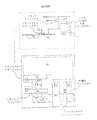
図4及び図5には、本発明により考えられたアクティブピクセルセンサ(APS)の共有増幅器トランジスターピクセルのアーキテクチャの平面図を示す。図4及び図5に示す実施態様は、発明者が知るかぎりでのベストモードを示す。他の物理的実施態様は実現可能であり、後述の説明から図4及び図5に示す実施態様のさまざまな変形態様である。図4に示すピクセル10は、数多の行及び列を有するピクセルのアレイ内での単一のピクセルである。2つの隣接ピクセルを図4に示し、各ピクセルで物理的に分離したフローティングディフュージョンを相互に、またソースフォロワ入力トランジスターとどのように相結合しているかを示す。図4に示す実施態様は2つの行の隣接ピクセル間に共有された増幅器のあるフォトダイオードピクセルを示す。なお、この新規なアーキテクチャはフォトゲートピクセルにも利用可能であることを指摘しておく。
【0010】
図4から分かるように、ピクセル10は、フォトダイオード光検出器12と、トランスファーゲート23と、フローティングディフュージョン25と、リセットゲート15のあるリセットトランジスター14とソースフォロワ入力信号トランジスター21(SIG)と、リセットトランジスター14とソースフォロワ入力トランジスター21の電源8(VDD)と、行選択ゲート(RSG)31のある行選択トランジスター30とからなる。図4に示すアーキテクチャは、フローティングディフュージョンが2つの行隣接ピクセルにより電気的に共有される2つの物理的及び空間的に分離された分離フローティングディフュージョン領域からなる以外は、図2に示す先行技術での共有増幅器ピクセルのそれと同じである。図4では、フローティングディフュージョン25は相互に物理的及び空間的に分離され、導電性インターコネクト層44により相互に及びソースフォロワ入力トランジスター21に電気的に接続している。図4に示すように、フローティングディフュージョン25、FDbはリセットトランジスター14のソース16により通常占有される面積を占有するように統合される。フローティングディフュージョン25、FDbと同じ電気的ノードにありながら、フローティングディフュージョン25、FDaはフローティングディフュージョン25、FDbから空間的に分離している。したがって、フローティングディフュージョン25、FDbと同じ電気的ノードにありながら、フローティングディフュージョン25、FDaはリセットトランジスター14のソース16として働かず、一方、フローティングディフュージョン25、FDbはリセットトランジスター14のソース16として働く。これは図2に示すピクセルとは対照的であり、図2では2つのフォトダイオードとトランスファーゲートは単一のフローティングディフュージョン領域と結合している。相接続した2つの物理的に分離したフローティングディフュージョンを有することにより、トランスファーゲートは光電荷を同じ物理的フローティングディフュージョン領域へ移動させる必要はないので、ピクセル境界内でのフォトダイオードとトランスファーゲートの配置に制限を与えることはない。このことはピクセル境界内でのフォトダイオードの同じ配置を一層容易に可能とし、よって図2に示すような同じでない配置を有することによる生じる起こり得る別のアーティファクトを軽減する。フローティングディフュージョンは相互に配線され、単一の電荷- 電圧変換ノードを形成するので、フローティングディフュージョン25は電気的に共有される。フローティングディフュージョンは導電性層36により相互に接続されているので、フローティングディフュージョン25 FDbがリセットされると、フローティングディフュージョン25 FDaもリセットされて同じ電圧になる。
【0011】
図5に示す実施態様は、4つの行と列の隣接ピクセル40が共通の構成部品を共有している場合を示す。図5から分かるように、4つのピクセル40はフォトダイオード光検出器42(PD1a、PD2a、PD1b、PD2b)と、トランスファーゲート43(TG1a、TG2a、TG1b、TG2b)と、フローティングディフュージョン45(FDa、FDb)と、リセットゲート15(RG)のあるリセットトランジスター14と、ソースフォロワ入力信号トランジスター21(SIG)と、リセットトランジスター14とソースフォロワ入力トランジスター21の電源8(VDD)と、行選択ゲート(RSG)31のある行選択トランジスター30とからなる。更に、図5に示すアーキテクチャは、フローティングディフュージョン45が電気的に接続し、4つの行及び列の隣接ピクセル40により共有される空間的に分離した分離フローティングディフュージョン領域からなる以外は、図3に示す先行技術での共有増幅器ピクセルのそれと同じである。図5では、フローティングディフュージョン45(FDa、FDb)は、導電性インターコネクト層55により相互に且つソースフォロワ入力トランジスター21に接続された物理的に分離したアクティブエリア領域である。フローティングディフュージョン45(FDa、FDb)のいずれもリセットトランジスター14のソース16として統合していない。代わりに、分離されたアクティブエリア領域がリセットトランジスター14のソース16として利用され、更に、この領域は導電性層55によりフローティングディフュージョン45(FDa、FDb)及びSIG21へ接続される。
【0012】
図5のアーキテクチャのレイアウトと図3(4つのフォトダイオードとトランスファーゲートが単一のフローティングディフュージョン領域に結合している)のそれとを比較すると、フローティングディフュージョン領域の面積は図5において、より小さい。結果として、図5での電荷- 電圧変換ノードの全静電容量はインターコネクトの静電容量のような電圧に無関係な静電容量からなる。結果として、電荷- 電圧変換は入力信号範囲であまり変動しなくなる。更に、図4と同様に、電気的に相接続した物理的に分離したフローティングディフュージョン領域45を有することにより、トランスファーゲート43は光電荷を単一のフローティングディフュージョン領域へ移動させる必要がないので、ピクセル境界内でのフォトダイオード42とトランスファーゲート43の配置に制限が加わらなくなる。図5から分かるように、このことによりピクセル境界内でのフォトダイオード42は同じ配置になり、図3に示す同じでない配置を有することにより起こり得る別のアーティファクトが軽減される。フローティングディフュージョンは互いに配線され、単一の電荷- 電圧変換ノードを形成するので、フローティングディフュージョン45はいまだに電気的に共有されている。リセットトランジスター14のソース16がリセットされると、フローティングディフュージョンは導電性層55により相互に接続されているので、双方のフローティングディフュージョン45(FDa、FDb)はリセットされて同じ電位になる。リセットゲート15のスイッチが切れると、リセットトランジスター14のソース16及びフローティングディフュージョン45(FDa、FDb)は一定でない(浮動している)。電荷がフォトダイオード42の1から移動すると、フローティングノードの電圧は相接続した領域の全静電容量に応じて変化する。
【0013】
この新規な相接続したフローティングディフュージョン領域のコンセプトで、4つのピクセル以上の作動構成部品を共有することが可能である。このことを図6に示す。この場合、行選択トランジスター30、リセットトランジスター14、及びソースフォロワ入力トランジスター21(SIG)は8つのピクセル50間で共有される。4つの空間的に分離されたフローティングディフュージョン46(FDa、FDb、FDcとFDd)は相互に配線され、リセットトランジスター14のソース16とソースフォロワ入力トランジスター21のゲート22に電気的に接続される。更に、フローティングディフュージョン領域46は最小化され、各ピクセル50内のフォトダイオード52の同じ配置が達成される。より小さいピクセル面積が光検出器以外の構成部品により占有されるので、すこぶる高い充填比が効率のよい増幅器の共有で得られる。単一の行選択トランジスター、リセットトランジスター及びソースフォロワ入力トランジスターを共有するピクセルの数は如何なる行の数にも任意に拡大される。行ごとに追加のトランスファーゲートバスを有することにより、如何なる列の数をも含むように拡大されることも可能である。単一の組の作動構成部品を共有するピクセルの数が増えるにつれて、相互に接続したフローティングディフュージョン領域の数とインターコネクトの静電容量により、フローティングディフュージョンの静電容量は増加する。結果として、最大の許容変換静電容量、又は最小の許容変換ゲインにより増幅器セットを共有するピクセルの数に実用的に制限がある。
【0014】
前述の説明は発明者による最善の実施態様を詳細に示している。上記実施態様の変形態様は当業者には容易に明らかであろう。したがって、本発明の範囲は添付した特許請求の範囲により確定されるべきである。
【0015】
【発明の効果】
上述の如く、本発明によれば、本当の相関二重サンプリング(CDS)のあるアクティブピクセルセンサを提供する。得られた効果は高い充填比、つまり小さなピクセル、電荷- 電圧変換の線形性及び各ピクセル内での同じ光検出器配置である。不利益な点は予測できない。
【図面の簡単な説明】
【図1】4つのトランジスターのフォトダイオードアクティブピクセルセンサのピクセルでの先行技術のアーキテクチャの略平面図である。
【図2】アクティブピクセルセンサの先行技術での共有増幅器のフォトダイオードピクセルアーキテクチャの二つの隣接ピクセルの平面図である。
【図3】アクティブピクセルセンサの先行技術での共有増幅器のフォトダイオードピクセルアーキテクチャの4つの隣接ピクセルの平面図である。
【図4】アクティブピクセルセンサの新規な共有増幅器のフォトダイオードピクセルアーキテクチャの4つの隣接ピクセルの平面図である。
【図5】アクティブピクセルセンサの新規な共有増幅器のフォトダイオードピクセルアーキテクチャの異なる実施態様の4つの隣接ピクセルの平面図である。
【図6】アクティブピクセルセンサの新規な共有増幅器のフォトダイオードピクセルアーキテクチャの異なる実施態様の8つの隣接ピクセルの平面図である。
【符号の説明】
8 VDD
10 ピクセル
12 フォトダイオード
14 リセットトランジスター
15 リセットトランジスターゲート
16 リセットトランジスターソース
21 ソースフォロワトランジスター
22 ソースフォロワトランジスターのゲート
23 トランスファーゲート
25 フローティングディフュージョン
30 行選択トランジスター
31 行選択ゲート
40 ピクセル
42 フォトダイオード
43 トランスファーゲート
44 インターコネクト層
45 フローティングディフュージョン
46 フローティングディフュージョン
50 ピクセル
43 トランスファーゲート
55 インターコネクト層
65 インターコネクト層[0001]
BACKGROUND OF THE INVENTION
The present invention relates to the field of solid state photosensors and imagers called active pixel sensors (APS) having an active circuit element associated with each pixel, and more particularly to a charge-to-voltage conversion region separated from a photodetector. The present invention relates to a solid-state imager that uses four transistor pixels of a pixel and correlated double sampling (CDS).
[0002]
[Prior art]
An APS is a solid-state imager, and each pixel typically includes a solid-state pixel element comprising light sensing means, resetting means, charge-to-voltage conversion means, row selection means, and all or partly an amplifier. The photo charge collected in the pixel is “Active Pixel Sensors: Are CCDs Dinosaurs?” By Eric Fossum, July 1993, SPIE Volume 1900-08-8194-1133. CCD's Dinosaurs?) "prior art as described in the literature, such as, is converted to a voltage or current corresponding in pixels. APS devices, in 1900-08-8194-1133 Volume of SPIE of July 1993 due to Lee Fosamu (E. Fossum) "active pixel sensor: CCD is whether dinosaurs? (Active Pixel Sensors: Are CCD 's Dinosaurs?) " And SPIE Proceedings Volume 2415 by RH Nixon, SE Kemeny, CO Staller and ER Fossum, “128x128 CMOS Photodiode-type Active Matrix Sensor with On-Chip Timing, Control and Signal Chain Electronics” "Pixel Sensor with On-chip Timing, Control and Signal Chain Electronics"), "Charge-Coupled Devices and Solid-State Optical Sensors V" in 1995 paper 34 . Thus, each line or row of the imager has been selected and then actuated to be read using a column selection signal. Row and column selection within an active pixel sensor is similar to word and bit selection in a memory device. Here, selecting an entire row is similar to selecting a word, and reading from one column of an active pixel sensor is similar to selecting or enabling a single bit line within that word. . The prior art active pixel sensor device shows an architecture that utilizes a four transistor design, where all four transistors are included in each and any pixel. The four transistors are typically transfer, row select, reset and source follower amplifier transistors. This architecture performs easily CDS, but advantages APS having the ability to lower readout noise is obtained is obtained there Ru, the 4T pixel is low packing ratio (fill factor). The fill ratio is the percentage of the pixel area that hits the photosensor. The contact regions and signal buses associated with the four transistors are located in each pixel, and the contact regions typically use a large pixel area due to the desired overlap and the space of the various layers, so that the pixel fill ratio otherwise This is reduced because the large area that would be utilized for the detector is used . The connection of each of the components to the appropriate timing signal is made by a metal bus that traverses the entire row of pixels. The metal bus is optically opaque, blocks the area of the photodetector and fits the pixel pitch. In addition, this reduces the pixel fill ratio. Decreasing the fill ratio reduces the sensitivity and saturation signal of the sensor. The above adversely affects the photographic speed and dynamic range of the sensor, and performance indicators that are important for obtaining high image quality.
[0003]
In U.S. Pat . Nos . 6,160,281 and 6,107,655 , Guidash uses four transistor pixels in the prior art by sharing floating diffusions, row select transistors, reset transistors, and source follower input transistors between adjacent row pixels. A pixel architecture that maintains functionality is disclosed. In the above architecture, a single floating diffusion region is shared between two or four adjacent pixels. The above architecture provides a high fill ratio but creates a physically large floating diffusion region. This results in a more nonlinear charge-voltage conversion due to the junction capacitance depending on the voltage of the floating diffusion, which is the majority of the total capacitance of the charge-voltage conversion node. Furthermore, trying to maintain the same arrangement of photodetectors within each pixel results in an inefficient layout of floating diffusions and reset transistors. Nonlinear charge-to-voltage conversion results in variable color balance artifacts. Another artifact is caused by the non-identical placement of photodetectors within each pixel. Both of the above artifacts adversely affect image quality.
[0004]
A typical prior art photodiode APS pixel is shown in FIG. 1 includes a photodiode (PD), a transfer transistor (TG), a floating diffusion (FD), a reset transistor having a reset gate (RG), a row selection transistor having a row selection gate (RSG), and a source. 4 is a four transistor pixel in the prior art consisting of a follower input signal transistor (SIG). The pixel filling ratio in the prior art is usually 25% or less.
[0005]
Another pixel architecture proposed by Guidash is shown in FIGS. In FIG. 2, two row adjacent pixels, pixel A and pixel B, each have a separate photodiode and transfer gate, PDa, PDb, TGa, TGb, but all other components, FD, RG, RSG and SIG. Share In FIG. 3, 1 and 2 represent rows, a and b represent columns, respectively, and four rows and columns adjacent pixels, pixels 1a, 2a, 1b and 2b represent separated PD's and TG's, PD1a, PD2a, It has PD1b, PD2b, TG1a, TG2a and TG2b, but shares all other components FD, RG, RSG and SIG. In this case, there are two transfer gate buses for each row to prevent mixing of signal charges from adjacent columns. While the above architecture provides a substantially higher fill ratio than the prior art pixel shown in FIG. 1, ie, a smaller pixel, there are a number of disadvantages as described above. Having a single floating diffusion region shared by either two neighboring pixels shown in FIG. 2 or four neighboring pixels shown in FIG. 3 results in a physically larger floating diffusion than that obtained in FIG. I understand that. Furthermore, it is clear from FIGS. 2 and 3 that the arrangement of photodetectors within adjacent pixel boundaries is not the same.
[0006]
Charges that are more linear with another pixel architecture with a high fill ratio, the ability to perform CDS, such as the shared amplifier pixel capability proposed by Guidash, and the same arrangement of photodetectors within each pixel -Sensors with voltage conversion are desired.
[0007]
[Problems to be solved by the invention]
The present invention has been made in view of the foregoing, and aims to provide a high fill ratio active pixel architecture capable of performing correlated double sampling (CDS).
[0008]
[Means for Solving the Problems]
The above objective is accomplished by an image sensor having a plurality of pixels arranged in a series of rows and columns comprising a semiconductor substrate having a plurality of pixels formed in rows and columns. Each of the at least two pixels has a charge-to-voltage conversion region that is spatially separated from each other and electrically connected to the source of a single reset transistor. In addition, pixels sharing the reset transistor share a selective electrical function with the amplifier. The preferred embodiment considers neighboring pixels, but does not have to be the immediate neighboring pixel. The functionality of the four transistor pixels is maintained, eliminating the need for a single floating diffusion region, the accompanying charge-to-voltage conversion non-linearity and asymmetry of adjacent photodetector placement within the pixel array, The high fill ratio of the shared amplifier pixel architecture is maintained.
[0009]
DETAILED DESCRIPTION OF THE INVENTION
4 and 5 show a plan view of the shared amplifier transistor pixel architecture of an active pixel sensor (APS) contemplated by the present invention. The embodiment shown in FIGS. 4 and 5 shows the best mode as far as the inventor is aware. Other physical implementations are possible and are various variations of the implementation shown in FIGS. 4 and 5 from the description below. The
[0010]
As can be seen from FIG. 4, the
[0011]
The embodiment shown in FIG. 5 illustrates the case where four rows and columns of
[0012]
If the architecture of the layout and 3 in FIG. 5 (four photodiodes and transfer gates are bonded are a single floating diffusion region) compared to that of the area of the floating diffusion region 5, smaller. As a result, the total capacitance of the charge-to-voltage conversion node in FIG. 5 consists of a capacitance independent of voltage, such as the capacitance of the interconnect. As a result, the charge-to-voltage conversion does not vary much over the input signal range. Further, similar to FIG. 4, by having a physically separated floating
[0013]
With this new phase-connected floating diffusion region concept, it is possible to share more than four pixel working components. This is shown in FIG. In this case, the
[0014]
The foregoing description details the best embodiment of the inventor. Variations of the above embodiment will be readily apparent to those skilled in the art. Accordingly, the scope of the invention should be determined by the appended claims.
[0015]
【The invention's effect】
As described above, the present invention provides an active pixel sensor with true correlated double sampling (CDS). The resulting effect is a high fill ratio, ie small pixels, linearity of charge-to-voltage conversion, and the same photodetector arrangement within each pixel. The disadvantages cannot be predicted.
[Brief description of the drawings]
FIG. 1 is a schematic plan view of a prior art architecture at a pixel of a four transistor photodiode active pixel sensor.
FIG. 2 is a plan view of two adjacent pixels of a prior art shared amplifier photodiode pixel architecture of an active pixel sensor.
FIG. 3 is a plan view of four adjacent pixels of a prior art shared pixel photodiode pixel architecture of an active pixel sensor.
FIG. 4 is a plan view of four adjacent pixels of a novel shared amplifier photodiode pixel architecture of an active pixel sensor.
FIG. 5 is a plan view of four adjacent pixels of different implementations of a novel shared amplifier photodiode pixel architecture of an active pixel sensor.
FIG. 6 is a plan view of eight adjacent pixels of different implementations of a novel shared amplifier photodiode pixel architecture of an active pixel sensor.
[Explanation of symbols]
8 VDD
10
44
Claims (2)
動作的に光検出器に結合される電荷−電圧変換領域を各ピクセルが有する、半導体基板内に形成された少なくとも2つの隣接ピクセルを有し、
前記少なくとも2つの隣接ピクセルは、少なくとも、当該ピクセルに対して動作する単一のリセットトランジスターを共有し、
前記少なくとも2つの隣接ピクセルの前記電荷−電圧変換領域は、相互に空間的に分離され、且つ1つの電気ノードを形成するように導電層によって相互に電気的に接続されており、且つ
前記1つの電気ノードを形成する前記電荷−電圧変換領域のうちの1つは前記リセットトランジスターのソースとして機能し、前記1つの電気ノードを形成する他の前記電荷−電圧変換領域は前記リセットトランジスターのソースとして機能しない、
画像センサ。An image sensor having a plurality of pixels arranged in a series of rows and columns,
Operatively charge is coupled to the light detector - having the voltage conversion region each pixel has at least two adjacent pixels formed in a semiconductor substrate,
The at least two adjacent pixels share at least a single reset transistor operating on the pixel;
The charge-voltage conversion regions of the at least two adjacent pixels are spatially separated from each other and electrically connected to each other by a conductive layer to form one electrical node; and the charge to form an electrical node - one of the voltage conversion region serves as a source of the reset transistor, said one other of the charge to form an electrical node - voltage conversion region functions as a source of the reset transistor do not do,
Image sensor.
半導体基板内に形成された所定のピクセル群の小集合を有し、
当該所定のピクセル群の小集合は、
隣接する少なくとも2つの行の隣接ピクセル群及び隣接する少なくとも2つの列の隣接ピクセル群からなる少なくとも4つのピクセルと、
前記少なくとも2つの行または列の隣接ピクセル群のそれぞれに共有されるとともに、相互に空間的に分離された少なくとも2つの電荷−電圧変換領域と
を有し、
前記電荷−電圧変換領域を、相互に、且つ前記所定のピクセル群の小集合によって共有される1つ以上のトランジスターに、電気的に接続するインターコネクト層と
を有する画像センサ。An image sensor having a plurality of pixels arranged in a series of rows and columns,
Having a small set of predetermined pixel groups formed in a semiconductor substrate;
The small set of the given pixel group is
At least four pixels comprising adjacent pixels in at least two adjacent rows and adjacent pixels in at least two columns;
At least two charge-voltage conversion regions shared by each of the at least two rows or columns of adjacent pixels and spatially separated from each other;
Have
And an interconnect layer that electrically connects the charge-voltage conversion region to one or more transistors shared by each other and by the small set of the predetermined pixel group.
Applications Claiming Priority (2)
| Application Number | Priority Date | Filing Date | Title |
|---|---|---|---|
| US224615 | 1998-12-31 | ||
| US09/224,615 US6657665B1 (en) | 1998-12-31 | 1998-12-31 | Active Pixel Sensor with wired floating diffusions and shared amplifier |
Publications (3)
| Publication Number | Publication Date |
|---|---|
| JP2000232216A JP2000232216A (en) | 2000-08-22 |
| JP2000232216A5 JP2000232216A5 (en) | 2007-02-08 |
| JP4401507B2 true JP4401507B2 (en) | 2010-01-20 |
Family
ID=22841426
Family Applications (1)
| Application Number | Title | Priority Date | Filing Date |
|---|---|---|---|
| JP37399899A Expired - Lifetime JP4401507B2 (en) | 1998-12-31 | 1999-12-28 | Active pixel sensor with wired floating diffusion and common amplifier |
Country Status (6)
| Country | Link |
|---|---|
| US (1) | US6657665B1 (en) |
| EP (1) | EP1017106B1 (en) |
| JP (1) | JP4401507B2 (en) |
| KR (1) | KR100805412B1 (en) |
| DE (1) | DE69943122D1 (en) |
| TW (1) | TW457815B (en) |
Families Citing this family (136)
| Publication number | Priority date | Publication date | Assignee | Title |
|---|---|---|---|---|
| US6977684B1 (en) * | 1998-04-30 | 2005-12-20 | Canon Kabushiki Kaisha | Arrangement of circuits in pixels, each circuit shared by a plurality of pixels, in image sensing apparatus |
| US6956605B1 (en) * | 1998-08-05 | 2005-10-18 | Canon Kabushiki Kaisha | Image pickup apparatus |
| US6239456B1 (en) | 1998-08-19 | 2001-05-29 | Photobit Corporation | Lock in pinned photodiode photodetector |
| US6310366B1 (en) * | 1999-06-16 | 2001-10-30 | Micron Technology, Inc. | Retrograde well structure for a CMOS imager |
| US6853044B1 (en) * | 1999-06-29 | 2005-02-08 | Hynix Semiconductor Inc. | Image sensor with improved dynamic range by applying negative voltage to unit pixel |
| US6476426B1 (en) * | 1999-07-06 | 2002-11-05 | Motorola, Inc. | Electronic component and method for improving pixel charge transfer in the electronic component |
| US7324144B1 (en) * | 1999-10-05 | 2008-01-29 | Canon Kabushiki Kaisha | Solid image pickup device, image pickup system and method of driving solid image pickup device |
| JP2001285717A (en) * | 2000-03-29 | 2001-10-12 | Toshiba Corp | Solid-state image pickup device |
| US6541794B1 (en) * | 2000-08-31 | 2003-04-01 | Motorola, Inc. | Imaging device and method |
| JP4500434B2 (en) * | 2000-11-28 | 2010-07-14 | キヤノン株式会社 | Imaging apparatus, imaging system, and imaging method |
| JP3792628B2 (en) * | 2002-09-02 | 2006-07-05 | 富士通株式会社 | Solid-state imaging device and image reading method |
| US7489352B2 (en) * | 2002-11-15 | 2009-02-10 | Micron Technology, Inc. | Wide dynamic range pinned photodiode active pixel sensor (APS) |
| CN100362854C (en) * | 2003-02-13 | 2008-01-16 | 松下电器产业株式会社 | Solid state image pickup apparatus, method for driving same, and camera using same |
| JP3794637B2 (en) | 2003-03-07 | 2006-07-05 | 松下電器産業株式会社 | Solid-state imaging device |
| JP2005005573A (en) * | 2003-06-13 | 2005-01-06 | Fujitsu Ltd | Image pickup device |
| US7859581B2 (en) * | 2003-07-15 | 2010-12-28 | Eastman Kodak Company | Image sensor with charge binning and dual channel readout |
| JP2005050951A (en) | 2003-07-31 | 2005-02-24 | Toshiba Corp | Solid-state image pickup device and charge transfer device |
| US7332786B2 (en) * | 2003-11-26 | 2008-02-19 | Micron Technology, Inc. | Anti-blooming storage pixel |
| US11282891B2 (en) | 2003-11-26 | 2022-03-22 | Samsung Electronics Co., Ltd. | Image sensor with a gated storage node linked to transfer gate |
| US7443437B2 (en) * | 2003-11-26 | 2008-10-28 | Micron Technology, Inc. | Image sensor with a gated storage node linked to transfer gate |
| JP4553612B2 (en) * | 2004-03-18 | 2010-09-29 | ルネサスエレクトロニクス株式会社 | Image pickup device and image pickup apparatus including the same |
| JP4230406B2 (en) * | 2004-04-27 | 2009-02-25 | 富士通マイクロエレクトロニクス株式会社 | Solid-state imaging device |
| US7652703B2 (en) * | 2004-07-12 | 2010-01-26 | Micron Technology, Inc. | Dual panel pixel readout in an imager |
| KR20070034063A (en) | 2004-07-20 | 2007-03-27 | 후지쯔 가부시끼가이샤 | CMOS image pickup device |
| JP4971586B2 (en) * | 2004-09-01 | 2012-07-11 | キヤノン株式会社 | Solid-state imaging device |
| JP2006073736A (en) * | 2004-09-01 | 2006-03-16 | Canon Inc | Photoelectric converter, solid state imaging device and system |
| JP5089017B2 (en) * | 2004-09-01 | 2012-12-05 | キヤノン株式会社 | Solid-state imaging device and solid-state imaging system |
| JP4916101B2 (en) | 2004-09-01 | 2012-04-11 | キヤノン株式会社 | Photoelectric conversion device, solid-state imaging device, and solid-state imaging system |
| JP2006108497A (en) * | 2004-10-07 | 2006-04-20 | Matsushita Electric Ind Co Ltd | Solid state imaging apparatus |
| US7973836B2 (en) * | 2004-10-28 | 2011-07-05 | Omnivision Technologies, Inc. | Camera, image sensor, and method for decreasing undesirable dark current |
| US7675094B2 (en) * | 2004-12-22 | 2010-03-09 | Omnivision Technologies, Inc. | Image sensor pixel having a transfer gate formed from P+ or N+ doped polysilicon |
| JP2006237361A (en) * | 2005-02-25 | 2006-09-07 | Iwate Toshiba Electronics Co Ltd | Cmos image sensor |
| JP4340248B2 (en) * | 2005-03-17 | 2009-10-07 | 富士通マイクロエレクトロニクス株式会社 | Method for manufacturing a semiconductor imaging device |
| JP4459099B2 (en) * | 2005-03-18 | 2010-04-28 | キヤノン株式会社 | Solid-state imaging device and camera |
| JP4518996B2 (en) * | 2005-04-22 | 2010-08-04 | シャープ株式会社 | Solid-state imaging device manufacturing method and electronic information device |
| US20060255381A1 (en) * | 2005-05-10 | 2006-11-16 | Micron Technology, Inc. | Pixel with gate contacts over active region and method of forming same |
| US7830437B2 (en) * | 2005-05-11 | 2010-11-09 | Aptina Imaging Corp. | High fill factor multi-way shared pixel |
| US7446357B2 (en) * | 2005-05-11 | 2008-11-04 | Micron Technology, Inc. | Split trunk pixel layout |
| US7342213B2 (en) * | 2005-06-01 | 2008-03-11 | Eastman Kodak Company | CMOS APS shared amplifier pixel with symmetrical field effect transistor placement |
| US8253214B2 (en) * | 2005-06-02 | 2012-08-28 | Omnivision Technologies, Inc. | CMOS shared amplifier pixels with output signal wire below floating diffusion interconnect for reduced floating diffusion capacitance |
| KR100718781B1 (en) * | 2005-06-15 | 2007-05-16 | 매그나칩 반도체 유한회사 | Cmos image sensors with compact pixel layout |
| ZA200605213B (en) * | 2005-06-24 | 2007-09-26 | J Lok Co | Device for forming partitioned film packages |
| KR20070006982A (en) * | 2005-07-09 | 2007-01-12 | 삼성전자주식회사 | Read out element shared type image sensor with improved light receiving efficiency |
| US7671314B2 (en) * | 2005-07-09 | 2010-03-02 | Samsung Electronics Co., Ltd. | Image sensor including active pixel sensor array with photoelectric conversion region |
| US7541628B2 (en) * | 2005-07-09 | 2009-06-02 | Samsung Electronics Co., Ltd. | Image sensors including active pixel sensor arrays |
| US7728896B2 (en) * | 2005-07-12 | 2010-06-01 | Micron Technology, Inc. | Dual conversion gain gate and capacitor and HDR combination |
| US7468532B2 (en) * | 2005-07-12 | 2008-12-23 | Aptina Imaging Corporation | Method and apparatus providing capacitor on an electrode of an imager photosensor |
| US7432540B2 (en) * | 2005-08-01 | 2008-10-07 | Micron Technology, Inc. | Dual conversion gain gate and capacitor combination |
| US20070035649A1 (en) * | 2005-08-10 | 2007-02-15 | Micron Technology, Inc. | Image pixel reset through dual conversion gain gate |
| US7511323B2 (en) * | 2005-08-11 | 2009-03-31 | Aptina Imaging Corporation | Pixel cells in a honeycomb arrangement |
| US20070040922A1 (en) * | 2005-08-22 | 2007-02-22 | Micron Technology, Inc. | HDR/AB on multi-way shared pixels |
| US7804117B2 (en) * | 2005-08-24 | 2010-09-28 | Aptina Imaging Corporation | Capacitor over red pixel |
| US7800146B2 (en) * | 2005-08-26 | 2010-09-21 | Aptina Imaging Corporation | Implanted isolation region for imager pixels |
| US7714917B2 (en) * | 2005-08-30 | 2010-05-11 | Aptina Imaging Corporation | Method and apparatus providing a two-way shared storage gate on a four-way shared pixel |
| US7244918B2 (en) * | 2005-08-30 | 2007-07-17 | Micron Technology, Inc. | Method and apparatus providing a two-way shared storage gate on a four-way shared pixel |
| JP4486015B2 (en) * | 2005-09-13 | 2010-06-23 | パナソニック株式会社 | Solid-state imaging device |
| JP4752447B2 (en) * | 2005-10-21 | 2011-08-17 | ソニー株式会社 | Solid-state imaging device and camera |
| JP4747781B2 (en) * | 2005-10-27 | 2011-08-17 | 船井電機株式会社 | Imaging device |
| JP4488366B2 (en) * | 2005-11-07 | 2010-06-23 | シャープ株式会社 | Method for manufacturing solid-state imaging device |
| JP4650249B2 (en) * | 2005-12-13 | 2011-03-16 | 船井電機株式会社 | Imaging device |
| JP4777772B2 (en) | 2005-12-28 | 2011-09-21 | 富士通セミコンダクター株式会社 | Semiconductor imaging device |
| KR100772892B1 (en) * | 2006-01-13 | 2007-11-05 | 삼성전자주식회사 | shared type image sensor with controllable floating diffusion capacitance |
| TWI316786B (en) * | 2006-01-24 | 2009-11-01 | Realtek Semiconductor Corp | Circuit utilizing op-sharing technique |
| US7602429B2 (en) * | 2006-02-01 | 2009-10-13 | Chi Wah Kok | Paired differential active pixel sensor |
| US7667183B2 (en) * | 2006-03-10 | 2010-02-23 | Samsung Electronics Co., Ltd. | Image sensor with high fill factor pixels and method for forming an image sensor |
| KR100688589B1 (en) * | 2006-03-10 | 2007-03-02 | 삼성전자주식회사 | Image sensor with improved fill factor and fabrication method thereof |
| US7538304B2 (en) * | 2006-03-30 | 2009-05-26 | Aptina Imaging Corporation | Reducing noise in an imager by sampling signals with a plurality of capacitances connected to an output line |
| US7608873B2 (en) * | 2006-04-27 | 2009-10-27 | Aptina Imaging Corporation | Buried-gated photodiode device and method for configuring and operating same |
| KR100776147B1 (en) | 2006-05-04 | 2007-11-15 | 매그나칩 반도체 유한회사 | Image sensor with extended pixel dynamic range incorporating transfer gate with a potential well |
| KR100776146B1 (en) * | 2006-05-04 | 2007-11-15 | 매그나칩 반도체 유한회사 | Cmos image sensor with improved performance incorporating pixels with burst reset operation |
| KR100818724B1 (en) * | 2006-07-19 | 2008-04-01 | 삼성전자주식회사 | CMOS image sensor and sensing method thereof |
| JP5132102B2 (en) * | 2006-08-01 | 2013-01-30 | キヤノン株式会社 | Photoelectric conversion device and imaging system using photoelectric conversion device |
| US8026966B2 (en) | 2006-08-29 | 2011-09-27 | Micron Technology, Inc. | Method, apparatus and system providing a storage gate pixel with high dynamic range |
| US7773138B2 (en) * | 2006-09-13 | 2010-08-10 | Tower Semiconductor Ltd. | Color pattern and pixel level binning for APS image sensor using 2×2 photodiode sharing scheme |
| JP4902308B2 (en) * | 2006-10-10 | 2012-03-21 | Hoya株式会社 | Image sensor |
| KR100849825B1 (en) * | 2007-03-14 | 2008-07-31 | 동부일렉트로닉스 주식회사 | Image sensor and method for manufacturing thereof |
| US7915702B2 (en) | 2007-03-15 | 2011-03-29 | Eastman Kodak Company | Reduced pixel area image sensor |
| US8072513B2 (en) | 2007-05-02 | 2011-12-06 | Canon Kabushiki Kaisha | Image capturing system, signal processing circuit, and signal processing method |
| US20080296639A1 (en) * | 2007-06-01 | 2008-12-04 | Dalsa Corporation | Semiconductor image sensor array device, apparatus comprising such a device and method for operating such a device |
| KR100880528B1 (en) * | 2007-06-01 | 2009-01-28 | 매그나칩 반도체 유한회사 | CMOS Image Sensors |
| US7964929B2 (en) * | 2007-08-23 | 2011-06-21 | Aptina Imaging Corporation | Method and apparatus providing imager pixels with shared pixel components |
| TWI504256B (en) * | 2008-04-07 | 2015-10-11 | Sony Corp | Solid-state imaging device, signal processing method of solid-state imaging device, and electronic apparatus |
| JP4661912B2 (en) * | 2008-07-18 | 2011-03-30 | ソニー株式会社 | Solid-state imaging device and camera system |
| JP5012782B2 (en) * | 2008-12-12 | 2012-08-29 | ソニー株式会社 | Imaging device |
| US8130302B2 (en) * | 2008-11-07 | 2012-03-06 | Aptina Imaging Corporation | Methods and apparatus providing selective binning of pixel circuits |
| JP5241454B2 (en) * | 2008-12-01 | 2013-07-17 | キヤノン株式会社 | Solid-state imaging device and imaging system using the same |
| JP5029624B2 (en) * | 2009-01-15 | 2012-09-19 | ソニー株式会社 | Solid-state imaging device and electronic apparatus |
| US8913166B2 (en) * | 2009-01-21 | 2014-12-16 | Canon Kabushiki Kaisha | Solid-state imaging apparatus |
| JP4553969B2 (en) * | 2009-03-02 | 2010-09-29 | ルネサスエレクトロニクス株式会社 | Imaging device |
| JP5471174B2 (en) * | 2009-08-28 | 2014-04-16 | ソニー株式会社 | SOLID-STATE IMAGING DEVICE, ITS MANUFACTURING METHOD, AND ELECTRONIC DEVICE |
| JP5564874B2 (en) * | 2009-09-25 | 2014-08-06 | ソニー株式会社 | Solid-state imaging device and electronic apparatus |
| TWI559763B (en) | 2009-10-01 | 2016-11-21 | 索尼半導體解決方案公司 | Image taking device and camera system |
| EP2315251A1 (en) * | 2009-10-22 | 2011-04-27 | STMicroelectronics (Crolles 2) SAS | Imager with vertical transfer gate and its method of fabrication |
| JP2010034576A (en) * | 2009-10-30 | 2010-02-12 | Renesas Technology Corp | Imaging device |
| FR2955701A1 (en) * | 2010-01-28 | 2011-07-29 | St Microelectronics Sa | COMPACT IMAGE SENSOR STRUCTURE |
| JP2011199196A (en) * | 2010-03-23 | 2011-10-06 | Toshiba Corp | Solid-state imaging device |
| US8274587B2 (en) | 2010-04-13 | 2012-09-25 | Aptina Imaging Corporation | Image sensor pixels with vertical charge transfer |
| JP5644177B2 (en) | 2010-05-07 | 2014-12-24 | ソニー株式会社 | Solid-state imaging device, manufacturing method thereof, and electronic apparatus |
| US8294077B2 (en) | 2010-12-17 | 2012-10-23 | Omnivision Technologies, Inc. | Image sensor having supplemental capacitive coupling node |
| US8471310B2 (en) | 2011-01-11 | 2013-06-25 | Aptina Imaging Corporation | Image sensor pixels with back-gate-modulated vertical transistor |
| US8497546B2 (en) | 2011-01-18 | 2013-07-30 | Aptina Imaging Corporation | Back-side-illuminated image sensors with bulk-charge-modulated image sensor pixels |
| US8697473B2 (en) | 2011-01-31 | 2014-04-15 | Aptina Imaging Corporation | Methods for forming backside illuminated image sensors with front side metal redistribution layers |
| US8928792B1 (en) | 2011-01-31 | 2015-01-06 | Aptina Imaging Corporation | CMOS image sensor with global shutter, rolling shutter, and a variable conversion gain, having pixels employing several BCMD transistors coupled to a single photodiode and dual gate BCMD transistors for charge storage and sensing |
| US8471315B1 (en) | 2011-01-31 | 2013-06-25 | Aptina Imaging Corporation | CMOS image sensor having global shutter pixels built using a buried channel transfer gate with a surface channel dark current drain |
| US8946845B1 (en) | 2011-02-02 | 2015-02-03 | Aptina Imaging Corporation | Stacked pixels for high resolution CMOS image sensors with BCMD charge detectors |
| US8785986B1 (en) | 2011-02-02 | 2014-07-22 | Aptina Imaging Corporation | BCMD image sensor with junction gate for back side or front side illumination |
| JP5547150B2 (en) * | 2011-09-16 | 2014-07-09 | 株式会社東芝 | Solid-state image sensor |
| JP5755111B2 (en) * | 2011-11-14 | 2015-07-29 | キヤノン株式会社 | Driving method of imaging apparatus |
| JP5954983B2 (en) | 2011-12-21 | 2016-07-20 | キヤノン株式会社 | Imaging apparatus, radiation imaging system, and manufacturing method of imaging apparatus |
| KR101967835B1 (en) | 2012-05-31 | 2019-04-10 | 삼성전자주식회사 | A unit pixel of a image sensor and a pixel array including thereof |
| JP5539458B2 (en) * | 2012-07-26 | 2014-07-02 | キヤノン株式会社 | Photoelectric conversion device and imaging system using photoelectric conversion device |
| JP6094086B2 (en) * | 2012-08-02 | 2017-03-15 | 株式会社ニコン | Imaging device and imaging apparatus |
| US9165959B2 (en) | 2013-02-25 | 2015-10-20 | Omnivision Technologies, Inc. | Image sensor with pixel units having mirrored transistor layout |
| US9369648B2 (en) | 2013-06-18 | 2016-06-14 | Alexander Krymski | Image sensors, methods, and pixels with tri-level biased transfer gates |
| JP6180882B2 (en) * | 2013-10-31 | 2017-08-16 | ソニーセミコンダクタソリューションズ株式会社 | Solid-state imaging device, signal processing device, and electronic device |
| CN104867949A (en) * | 2014-02-21 | 2015-08-26 | 恒景科技股份有限公司 | Image sensor |
| JP6334203B2 (en) * | 2014-02-28 | 2018-05-30 | ソニー株式会社 | Solid-state imaging device and electronic device |
| US9526468B2 (en) | 2014-09-09 | 2016-12-27 | General Electric Company | Multiple frame acquisition for exposure control in X-ray medical imagers |
| US9832407B2 (en) | 2014-11-26 | 2017-11-28 | Semiconductor Components Industries, Llc | Global shutter image sensor pixels having improved shutter efficiency |
| FR3030884B1 (en) * | 2014-12-19 | 2016-12-30 | Stmicroelectronics (Grenoble 2) Sas | PIXEL STRUCTURE WITH MULTIPLE PHOTOSITES |
| DE112015006045T5 (en) * | 2015-01-22 | 2018-02-15 | X-Fab Semiconductor Foundries Ag | CMOS image sensor pixel |
| JP6555890B2 (en) * | 2015-01-23 | 2019-08-07 | キヤノン株式会社 | Imaging apparatus, imaging system, and driving method of imaging apparatus |
| US9502457B2 (en) | 2015-01-29 | 2016-11-22 | Semiconductor Components Industries, Llc | Global shutter image sensor pixels having centralized charge storage regions |
| TWI696278B (en) | 2015-03-31 | 2020-06-11 | 日商新力股份有限公司 | Image sensor, camera device and electronic device |
| TWI701819B (en) * | 2015-06-09 | 2020-08-11 | 日商索尼半導體解決方案公司 | Imaging element, driving method and electronic equipment |
| US10341592B2 (en) | 2015-06-09 | 2019-07-02 | Sony Semiconductor Solutions Corporation | Imaging element, driving method, and electronic device |
| US10014333B2 (en) * | 2015-08-26 | 2018-07-03 | Semiconductor Components Industries, Llc | Back-side illuminated pixels with interconnect layers |
| KR20170056909A (en) | 2015-11-16 | 2017-05-24 | 삼성전자주식회사 | Image sensor and electronic device having the same |
| KR102541701B1 (en) | 2016-01-15 | 2023-06-13 | 삼성전자주식회사 | CMOS Image Sensor |
| US9653513B1 (en) * | 2016-04-08 | 2017-05-16 | Himax Imaging Limited | CMOS image sensor and a method of forming the same |
| US11276725B2 (en) * | 2016-11-28 | 2022-03-15 | NewSight Imaging Ltd. | Active-pixel sensor array |
| WO2018105334A1 (en) | 2016-12-09 | 2018-06-14 | ソニーセミコンダクタソリューションズ株式会社 | Solid-state image pickup element and electronic apparatus |
| US11923385B2 (en) * | 2018-05-16 | 2024-03-05 | Sony Semiconductor Solutions Corporation | Solid-state imaging device and solid-state imaging apparatus |
| KR102591525B1 (en) * | 2018-05-28 | 2023-10-23 | 에스케이하이닉스 주식회사 | Image Sensor Including an Unit Pixel Block Having a Common Selection Transistor |
| JP7433863B2 (en) * | 2019-11-27 | 2024-02-20 | キヤノン株式会社 | Photoelectric conversion devices, imaging systems, and mobile objects |
| US11658201B2 (en) | 2021-08-25 | 2023-05-23 | Silead Inc. | Dual conversion gain image sensor pixels |
Family Cites Families (23)
| Publication number | Priority date | Publication date | Assignee | Title |
|---|---|---|---|---|
| JPH0831585B2 (en) * | 1987-04-20 | 1996-03-27 | オリンパス光学工業株式会社 | Solid-state imaging device |
| JPH0795829B2 (en) * | 1988-07-26 | 1995-10-11 | 株式会社東芝 | Solid-state imaging device |
| JP2977060B2 (en) * | 1992-01-29 | 1999-11-10 | オリンパス光学工業株式会社 | Solid-state imaging device and control method thereof |
| US5471515A (en) | 1994-01-28 | 1995-11-28 | California Institute Of Technology | Active pixel sensor with intra-pixel charge transfer |
| US5631704A (en) | 1994-10-14 | 1997-05-20 | Lucent Technologies, Inc. | Active pixel sensor and imaging system having differential mode |
| US5625210A (en) | 1995-04-13 | 1997-04-29 | Eastman Kodak Company | Active pixel sensor integrated with a pinned photodiode |
| EP0757475B1 (en) * | 1995-08-02 | 2004-01-21 | Canon Kabushiki Kaisha | Solid-state image sensing device with common output line |
| US5587596A (en) | 1995-09-20 | 1996-12-24 | National Semiconductor Corporation | Single MOS transistor active pixel sensor cell with automatic anti-blooming and wide dynamic range |
| US5608243A (en) * | 1995-10-19 | 1997-03-04 | National Semiconductor Corporation | Single split-gate MOS transistor active pixel sensor cell with automatic anti-blooming and wide dynamic range |
| US5789774A (en) | 1996-03-01 | 1998-08-04 | Foveonics, Inc. | Active pixel sensor cell that minimizes leakage current |
| US5721425A (en) | 1996-03-01 | 1998-02-24 | National Semiconductor Corporation | Active pixel sensor cell that reduces the effect of 1/f noise, increases the voltage range of the cell, and reduces the size of the cell |
| US5872371A (en) * | 1997-02-27 | 1999-02-16 | Eastman Kodak Company | Active pixel sensor with punch-through reset and cross-talk suppression |
| US5838650A (en) | 1996-06-26 | 1998-11-17 | Lucent Technologies Inc. | Image quality compensation method and apparatus for holographic data storage system |
| JP3579194B2 (en) * | 1996-09-17 | 2004-10-20 | 株式会社東芝 | Driving method of solid-state imaging device |
| JP3383523B2 (en) * | 1996-09-19 | 2003-03-04 | 株式会社東芝 | Solid-state imaging device and driving method thereof |
| US5760458A (en) | 1996-10-22 | 1998-06-02 | Foveonics, Inc. | Bipolar-based active pixel sensor cell with poly contact and increased capacitive coupling to the base region |
| US5786623A (en) | 1996-10-22 | 1998-07-28 | Foveonics, Inc. | Bipolar-based active pixel sensor cell with metal contact and increased capacitive coupling to the base region |
| US6160281A (en) * | 1997-02-28 | 2000-12-12 | Eastman Kodak Company | Active pixel sensor with inter-pixel function sharing |
| US5847422A (en) | 1997-05-19 | 1998-12-08 | Foveonics, Inc. | MOS-based active pixel sensor cell that utilizes the parasitic bipolar action of the cell to output image data |
| JP3320335B2 (en) * | 1997-05-30 | 2002-09-03 | キヤノン株式会社 | Photoelectric conversion device and contact image sensor |
| US6107655A (en) * | 1997-08-15 | 2000-08-22 | Eastman Kodak Company | Active pixel image sensor with shared amplifier read-out |
| JP3413078B2 (en) * | 1997-10-06 | 2003-06-03 | キヤノン株式会社 | Photoelectric conversion device and contact image sensor |
| US6466266B1 (en) * | 1998-07-28 | 2002-10-15 | Eastman Kodak Company | Active pixel sensor with shared row timing signals |
-
1998
- 1998-12-31 US US09/224,615 patent/US6657665B1/en not_active Expired - Lifetime
-
1999
- 1999-10-30 TW TW088118900A patent/TW457815B/en not_active IP Right Cessation
- 1999-12-01 DE DE69943122T patent/DE69943122D1/en not_active Expired - Lifetime
- 1999-12-01 EP EP99204061A patent/EP1017106B1/en not_active Expired - Lifetime
- 1999-12-28 KR KR1019990063215A patent/KR100805412B1/en active IP Right Grant
- 1999-12-28 JP JP37399899A patent/JP4401507B2/en not_active Expired - Lifetime
Also Published As
| Publication number | Publication date |
|---|---|
| DE69943122D1 (en) | 2011-02-24 |
| TW457815B (en) | 2001-10-01 |
| KR100805412B1 (en) | 2008-02-20 |
| EP1017106A3 (en) | 2004-02-11 |
| US6657665B1 (en) | 2003-12-02 |
| EP1017106B1 (en) | 2011-01-12 |
| EP1017106A2 (en) | 2000-07-05 |
| JP2000232216A (en) | 2000-08-22 |
| KR20000052598A (en) | 2000-08-25 |
Similar Documents
| Publication | Publication Date | Title |
|---|---|---|
| JP4401507B2 (en) | Active pixel sensor with wired floating diffusion and common amplifier | |
| JP2000232216A5 (en) | ||
| EP0862219B1 (en) | Active pixel sensor in which adjacent pixels share an integrated electrical element | |
| KR100750778B1 (en) | Photodiode active pixel sensor with shared reset signal row select | |
| KR100637945B1 (en) | Active pixel image sensor with shared amplifier read-out | |
| EP0913869B1 (en) | Active pixel sensor with programmable color balance | |
| JP4402786B2 (en) | Active pixel sensor and control method thereof | |
| KR101254360B1 (en) | Cmos image sensor pixel with selectable binning | |
| JP5219348B2 (en) | Image sensor including active pixel sensor array | |
| EP0977426B1 (en) | Active pixel sensor with row control busses shared between adjacent pixel rows | |
| US7230224B2 (en) | Solid state image pickup device with two photosensitive fields per one pixel | |
| US6486913B1 (en) | Pixel array with shared reset circuitry | |
| JP2011066506A (en) | Solid-state imaging element | |
| EP0809394B1 (en) | Active pixel sensor with switched supply row select | |
| JP6702371B2 (en) | Imaging device and imaging device | |
| JP7468594B2 (en) | Image pickup element and image pickup device | |
| US20240022800A1 (en) | Image sensor and electronic device including the same | |
| JP4444990B2 (en) | Solid-state imaging device |
Legal Events
| Date | Code | Title | Description |
|---|---|---|---|
| A521 | Request for written amendment filed |
Free format text: JAPANESE INTERMEDIATE CODE: A523 Effective date: 20061220 |
|
| A621 | Written request for application examination |
Free format text: JAPANESE INTERMEDIATE CODE: A621 Effective date: 20061220 |
|
| A131 | Notification of reasons for refusal |
Free format text: JAPANESE INTERMEDIATE CODE: A131 Effective date: 20080924 |
|
| A977 | Report on retrieval |
Free format text: JAPANESE INTERMEDIATE CODE: A971007 Effective date: 20080925 |
|
| A601 | Written request for extension of time |
Free format text: JAPANESE INTERMEDIATE CODE: A601 Effective date: 20081211 |
|
| A602 | Written permission of extension of time |
Free format text: JAPANESE INTERMEDIATE CODE: A602 Effective date: 20081216 |
|
| A521 | Request for written amendment filed |
Free format text: JAPANESE INTERMEDIATE CODE: A523 Effective date: 20090318 |
|
| A131 | Notification of reasons for refusal |
Free format text: JAPANESE INTERMEDIATE CODE: A131 Effective date: 20090609 |
|
| A521 | Request for written amendment filed |
Free format text: JAPANESE INTERMEDIATE CODE: A523 Effective date: 20090903 |
|
| TRDD | Decision of grant or rejection written | ||
| A01 | Written decision to grant a patent or to grant a registration (utility model) |
Free format text: JAPANESE INTERMEDIATE CODE: A01 Effective date: 20091020 |
|
| A01 | Written decision to grant a patent or to grant a registration (utility model) |
Free format text: JAPANESE INTERMEDIATE CODE: A01 |
|
| A61 | First payment of annual fees (during grant procedure) |
Free format text: JAPANESE INTERMEDIATE CODE: A61 Effective date: 20091028 |
|
| R150 | Certificate of patent or registration of utility model |
Free format text: JAPANESE INTERMEDIATE CODE: R150 Ref document number: 4401507 Country of ref document: JP Free format text: JAPANESE INTERMEDIATE CODE: R150 |
|
| FPAY | Renewal fee payment (event date is renewal date of database) |
Free format text: PAYMENT UNTIL: 20121106 Year of fee payment: 3 |
|
| FPAY | Renewal fee payment (event date is renewal date of database) |
Free format text: PAYMENT UNTIL: 20121106 Year of fee payment: 3 |
|
| FPAY | Renewal fee payment (event date is renewal date of database) |
Free format text: PAYMENT UNTIL: 20121106 Year of fee payment: 3 |
|
| S111 | Request for change of ownership or part of ownership |
Free format text: JAPANESE INTERMEDIATE CODE: R313113 |
|
| FPAY | Renewal fee payment (event date is renewal date of database) |
Free format text: PAYMENT UNTIL: 20121106 Year of fee payment: 3 |
|
| R350 | Written notification of registration of transfer |
Free format text: JAPANESE INTERMEDIATE CODE: R350 |
|
| FPAY | Renewal fee payment (event date is renewal date of database) |
Free format text: PAYMENT UNTIL: 20121106 Year of fee payment: 3 |
|
| FPAY | Renewal fee payment (event date is renewal date of database) |
Free format text: PAYMENT UNTIL: 20131106 Year of fee payment: 4 |
|
| R250 | Receipt of annual fees |
Free format text: JAPANESE INTERMEDIATE CODE: R250 |
|
| R250 | Receipt of annual fees |
Free format text: JAPANESE INTERMEDIATE CODE: R250 |
|
| R250 | Receipt of annual fees |
Free format text: JAPANESE INTERMEDIATE CODE: R250 |
|
| R250 | Receipt of annual fees |
Free format text: JAPANESE INTERMEDIATE CODE: R250 |
|
| R154 | Certificate of patent or utility model (reissue) |
Free format text: JAPANESE INTERMEDIATE CODE: R154 |
|
| R250 | Receipt of annual fees |
Free format text: JAPANESE INTERMEDIATE CODE: R250 |
|
| R250 | Receipt of annual fees |
Free format text: JAPANESE INTERMEDIATE CODE: R250 |
|
| R250 | Receipt of annual fees |
Free format text: JAPANESE INTERMEDIATE CODE: R250 |
|
| R250 | Receipt of annual fees |
Free format text: JAPANESE INTERMEDIATE CODE: R250 |
|
| EXPY | Cancellation because of completion of term |