JP4400387B2 - Conveying apparatus and recording apparatus provided with the conveying apparatus - Google Patents
Conveying apparatus and recording apparatus provided with the conveying apparatus Download PDFInfo
- Publication number
- JP4400387B2 JP4400387B2 JP2004270473A JP2004270473A JP4400387B2 JP 4400387 B2 JP4400387 B2 JP 4400387B2 JP 2004270473 A JP2004270473 A JP 2004270473A JP 2004270473 A JP2004270473 A JP 2004270473A JP 4400387 B2 JP4400387 B2 JP 4400387B2
- Authority
- JP
- Japan
- Prior art keywords
- conveyance
- transport
- drive roller
- roller
- outer peripheral
- Prior art date
- Legal status (The legal status is an assumption and is not a legal conclusion. Google has not performed a legal analysis and makes no representation as to the accuracy of the status listed.)
- Expired - Fee Related
Links
Images


Description
本発明は、両端支持部及び中央支持部において回転可能に支持され、駆動力源による回転駆動力が伝達されて回転する搬送駆動ローラと、搬送駆動ローラの中央支持部を被搬送体の搬送経路外で摺接支持する中支え手段とを備え、駆動力源の回転駆動力で搬送駆動ローラを回転させることによって、被搬送体押圧手段により搬送駆動ローラの外周面に押圧されて密着している状態の被搬送体が所定の搬送方向へ搬送される搬送装置に関する。 The present invention relates to a conveyance drive roller that is rotatably supported by both end support portions and a central support portion and is rotated by a rotational driving force transmitted by a driving force source, and a conveyance path of a conveyance target member through a central support portion of the conveyance drive roller. An intermediate support means for sliding and supporting outside, and the carrier driving roller is rotated by the rotational driving force of the driving force source so as to be pressed and adhered to the outer peripheral surface of the carrier driving roller by the carrier pressing means. The present invention relates to a transport device that transports a transported body in a predetermined transport direction.
例えば、インクジェットプリンタ等の記録装置において、記録紙等の被記録材を所定の搬送量で所定の搬送方向へ高精度に搬送するための搬送手段としては、円柱体形状の軸体の外周面に塗布した塗料にセラミック粉体等を付着させる等の工程により外周面に高摩擦抵抗被膜が形成された搬送駆動ローラを備えたものが一般的である。搬送駆動ローラは、記録装置に回転可能に支持され、モータ等の回転駆動力源による回転駆動力が伝達されて回転することで、外周面に当接して高摩擦抵抗被膜の摩擦抵抗により外周面に密着している状態の被記録材が回転方向へ搬送される(例えば特許文献1を参照)。被記録材の搬送精度は、記録装置の記録画質に直接影響するため、記録装置における搬送量及び搬送方向の傾き等について極めて高い精度が要求される。そのため、従来は、搬送駆動ローラをより固い材質でより外径を大きくして剛性を高めることによって、自重による搬送駆動ローラの撓みや被搬送体押圧手段の押圧力による搬送駆動ローラの撓みを生じにくくし、搬送駆動ローラの撓みにより生じる搬送精度の低下を低減させるのが一般的であった。 For example, in a recording apparatus such as an ink jet printer, a conveying means for conveying a recording material such as recording paper in a predetermined conveying direction with a predetermined conveying amount with high accuracy is provided on the outer peripheral surface of a cylindrical shaft body. In general, there is provided a conveyance drive roller having a high frictional resistance film formed on the outer peripheral surface by a process such as attaching ceramic powder to the applied paint. The conveyance driving roller is rotatably supported by the recording apparatus, and is rotated by a rotational driving force transmitted from a rotational driving force source such as a motor, so that the outer circumferential surface is brought into contact with the outer circumferential surface by the frictional resistance of the high frictional resistance film. The recording material in close contact with the recording medium is conveyed in the rotation direction (see, for example, Patent Document 1). Since the conveyance accuracy of the recording material directly affects the recording image quality of the recording apparatus, extremely high accuracy is required for the conveyance amount and the inclination of the conveyance direction in the recording apparatus. For this reason, conventionally, by increasing the rigidity by increasing the outer diameter of the transport drive roller with a harder material, bending of the transport drive roller due to its own weight or bending of the transport drive roller due to the pressing force of the transported body pressing means occurs. Generally, it is difficult to reduce the decrease in the conveyance accuracy caused by the bending of the conveyance drive roller.
このような記録装置においては、記録を実行可能な被記録材の最大サイズに応じた長さの搬送駆動ローラが配設される必要があるが、その長さが長くなるほど搬送駆動ローラの自重や被記録材を搬送駆動ローラの外周面に密着させる際の押圧力等によって生じる搬送駆動ローラの撓み量が大きくなる。そのため、両端部のみで搬送駆動ローラを回転可能に支持した状態では、その搬送駆動ローラの撓みによる搬送精度の低下が問題となってくる。そこで、このような課題を解決するために、搬送駆動ローラを両端部近傍で回転可能に支持するとともに、さらに搬送駆動ローラの中央近傍において搬送駆動ローラを回転可能に支持する3点支持構成とした記録装置が公知である(例えば特許文献2を参照)。搬送駆動ローラの中央近傍において搬送駆動ローラの撓みを規制することができるので、その支持位置を調節することによって、搬送駆動ローラの自重や被記録材を搬送駆動ローラの外周面に密着させる際の押圧力等によって生じる搬送駆動ローラの撓みを低減させることができる。それによって、搬送駆動ローラの撓みによる被記録材の搬送精度の低下を低減させることができる。 In such a recording apparatus, it is necessary to dispose a transport driving roller having a length corresponding to the maximum size of the recording material that can perform recording. The amount of bending of the transport drive roller caused by the pressing force when the recording material is brought into close contact with the outer peripheral surface of the transport drive roller becomes large. For this reason, in a state where the transport driving roller is rotatably supported only at both ends, a decrease in transport accuracy due to bending of the transport driving roller becomes a problem. Therefore, in order to solve such a problem, the conveyance drive roller is rotatably supported in the vicinity of both ends, and further, the conveyance drive roller is rotatably supported in the vicinity of the center of the conveyance drive roller. A recording apparatus is known (see, for example, Patent Document 2). Since the deflection of the transport drive roller can be restricted near the center of the transport drive roller, adjusting the support position allows the weight of the transport drive roller and the recording material to be in close contact with the outer peripheral surface of the transport drive roller. It is possible to reduce the bending of the transport driving roller caused by the pressing force or the like. Accordingly, it is possible to reduce a decrease in the conveyance accuracy of the recording material due to the bending of the conveyance drive roller.
例えば、インクジェットプリンタ等の記録装置においては、上述した搬送駆動ローラにより被搬送体として記録紙等の被記録材を搬送する構成を有するものが一般的である。通常の記録装置は、トレイ等に積重された記録紙を自動給送する自動給紙装置等を備えている。自動給紙装置は、トレイ等に積重された記録紙の最上位の記録紙を、その先端が搬送駆動ローラの外周面に到達する位置まで給送経路を介して自動給送する。このような記録装置は、その給送経路に搬送駆動ローラの外周面と平行な給送案内面を有する給送案内部材が設けられており、給送される記録紙は、その給送案内面に摺接しながら搬送駆動ローラの外周面へ向けて給送されるようになっているのが一般的である。また、搬送駆動ローラの回転によって搬送される記録紙の搬送経路には、給送経路と同様に、搬送駆動ローラの外周面と平行な搬送案内面を有する搬送案内部材(いわゆるプラテン等)が設けられているのが一般的である。搬送経路を搬送される記録紙は、その搬送案内面に摺接しながら搬送され、それによって、搬送経路上を搬送方向と直交する方向へ往復動する記録ヘッドのヘッド面との間隔(いわゆるプラテン・ギャップ、以下PGという)が高精度に規定された状態で搬送される。 For example, a recording apparatus such as an ink jet printer generally has a configuration in which a recording material such as recording paper is conveyed as a conveyance target by the above-described conveyance driving roller. A normal recording apparatus includes an automatic paper feeding device that automatically feeds recording papers stacked on a tray or the like. The automatic sheet feeder automatically feeds the uppermost recording sheet stacked on a tray or the like through a feeding path to a position where the leading end reaches the outer peripheral surface of the transport driving roller. In such a recording apparatus, a feeding guide member having a feeding guide surface parallel to the outer peripheral surface of the transport driving roller is provided in the feeding path, and the recording paper to be fed is supplied with the feeding guide surface. In general, the sheet is fed toward the outer peripheral surface of the transport driving roller while being in sliding contact with the roller. Also, a conveyance guide member (a so-called platen or the like) having a conveyance guide surface parallel to the outer peripheral surface of the conveyance drive roller is provided in the conveyance path of the recording paper conveyed by the rotation of the conveyance drive roller, similarly to the feeding path. It is common that The recording paper transported along the transport path is transported while being slidably contacted with the transport guide surface, and thereby the distance between the head surface of the recording head that reciprocates in the direction perpendicular to the transport direction on the transport path (so-called platen A gap (hereinafter referred to as PG) is conveyed in a state defined with high accuracy.
つまり、自動給紙装置による搬送駆動ローラへの被記録材の給送精度は、給送案内部材の給送案内面によって、搬送駆動ローラの回転により搬送される被記録材の搬送精度は、搬送案内部材の搬送案内面によって、それぞれ左右されることになり、給送案内面及び搬送案内面は、搬送駆動ローラの回転軸に対して、高い精度で平行な平坦面を有した状態で、かつ搬送駆動ローラの外周面と適正な位置関係となるように配置されるのが望ましい。
しかし、現実には、給送案内部材や搬送案内部材は、被記録材の幅方向に長尺な部材であり、製造誤差の範囲内で僅かながら反りや湾曲変形、歪み等が生じて形成されている。そのため、給送案内面或いは搬送案内面に反りや湾曲変形が生じてしまうことになる。それによって、被記録材の給送経路或いは搬送経路において、被記録材のスキュー(給送方向或いは搬送方向に対する傾き)や被記録材の撓み、浮き上がり等が生じて、給送精度の低下(紙詰まりや被記録材の折れ曲がり等)や搬送精度の低下による記録精度の低下(搬送方向に対する記録紙の先端位置ずれや傾きによる記録位置ずれ、被記録材の浮き上がりによるPG精度の低下や被記録材の記録ヘッドへの接触による被記録材の汚れ等)が生じてしまう虞があった。
In other words, the feeding accuracy of the recording material to the conveyance driving roller by the automatic paper feeder is the conveyance accuracy of the recording material conveyed by the rotation of the conveyance driving roller by the feeding guide surface of the feeding guide member. The feed guide surface and the transport guide surface have a flat surface parallel to the rotation axis of the transport drive roller with high accuracy, and are influenced by the transport guide surface of the guide member, and It is desirable to arrange them so as to have an appropriate positional relationship with the outer peripheral surface of the transport drive roller.
However, in reality, the feed guide member and the transport guide member are members that are long in the width direction of the recording material, and are formed with slight warpage, bending deformation, distortion, and the like within the range of manufacturing errors. ing. For this reason, the feeding guide surface or the conveyance guide surface is warped or curved. As a result, the skew of the recording material (inclination with respect to the feeding direction or the conveyance direction), the bending of the recording material, the lifting, etc. occur in the feeding path or the conveying path of the recording material, and the feeding accuracy is reduced (paper Deterioration in recording accuracy due to clogging, bending of the recording material, etc., or reduction in conveyance accuracy (recording position deviation due to deviation or inclination of the recording paper relative to the conveyance direction, decrease in PG accuracy due to lifting of the recording material, or recording material The recording material may become dirty due to contact with the recording head.
本発明は、このような状況に鑑み成されたものであり、その課題は、給送された被搬送体を搬送駆動ローラの回転によって所定の搬送方向へ搬送する搬送装置において、給送案内部材や搬送案内部材の反りや湾曲変形、歪み等による給送精度の低下や搬送精度の低下を低減させることにある。 The present invention has been made in view of such a situation, and the problem is that a feeding guide member is provided in a conveying device that conveys a fed object to be conveyed in a predetermined conveying direction by rotation of a conveying driving roller. Another object is to reduce a decrease in feeding accuracy and a decrease in conveying accuracy due to warping, bending deformation, distortion, etc. of the conveying guide member.
上記課題を達成するため、本発明の第1の態様は、両端支持部及び中央支持部において回転可能に支持され、駆動力源による回転駆動力が伝達されて回転する搬送駆動ローラと、該搬送駆動ローラの前記中央支持部を被搬送体の搬送経路外で摺接支持する中支え手段とを備え、前記駆動力源の回転駆動力で前記搬送駆動ローラを回転させることによって、前記搬送駆動ローラの外周面に当接している被搬送体が所定の搬送方向へ搬送される搬送装置であって、前記中支え手段による前記中央支持部の摺接支持位置を前記搬送駆動ローラの回転軸と略直交する方向へ変位調節可能な支持位置調節手段と、被搬送体の給送手段から給送される被搬送体を前記搬送駆動ローラの外周面の適正な位置に適正な姿勢で当接させる如く案内する前記搬送駆動ローラの回転軸と略平行な給送案内面を有する給送案内部材とを備え、前記搬送駆動ローラの外周面と前記給送案内面との間隔が略均等になる如く、前記支持位置調節手段による前記中支え手段の変位に連動して前記給送案内面が少なくとも一部変位する、ことを特徴とした搬送装置である。 In order to achieve the above object, a first aspect of the present invention includes a conveyance driving roller that is rotatably supported at both end support portions and a central support portion, and rotates by receiving a rotational driving force from a driving force source, and the conveyance driving roller. Intermediate support means for slidingly supporting the center support portion of the drive roller outside the transport path of the transported body, and rotating the transport drive roller with the rotational drive force of the drive force source, thereby transporting the transport drive roller A transporting device in which a transported body that is in contact with the outer peripheral surface of the transporting device is transported in a predetermined transporting direction, and the sliding support position of the center support portion by the intermediate support means is substantially the same as the rotation shaft of the transporting drive roller. The supporting position adjusting means capable of adjusting the displacement in the orthogonal direction and the transported body fed from the transporting means of the transported body are brought into contact with the proper position on the outer peripheral surface of the transport driving roller in an appropriate posture. The transporter to guide A feed guide member having a feed guide surface substantially parallel to the rotation axis of the roller, and the support position adjusting means so that the distance between the outer peripheral surface of the transport drive roller and the feed guide surface is substantially uniform. The feeding guide surface is displaced at least partially in conjunction with the displacement of the middle support means by the carrier device.
前述したように、自動給紙装置による搬送駆動ローラへの被記録材の給送精度は、給送案内部材の給送案内面によって左右されることになり、給送案内面は、搬送駆動ローラの回転軸に対して、高い精度で平行な平坦面を有した状態で、かつ搬送駆動ローラの外周面と適正な位置関係となるように配置されるのが望ましい。しかし、現実には、給送案内部材は、被記録材の幅方向に長尺な部材であり、製造誤差の範囲内で僅かながら反りや湾曲変形、歪み等が生じて形成されている。そのため、給送案内面に反りや湾曲変形が生じてしまい、被記録材の給送経路において、被記録材のスキューや被記録材の撓み、浮き上がり等が生じてしまう。
そこで、搬送駆動ローラの外周面と給送案内面との間隔が略均等になる如く、支持位置調節手段による中支え手段の変位に連動して給送案内面が変位するように給送案内部材を配設する。
As described above, the feeding accuracy of the recording material to the transport driving roller by the automatic paper feeding device depends on the feeding guide surface of the feeding guide member, and the feeding guide surface is the transport driving roller. It is desirable to have a flat surface parallel to the rotating shaft with high accuracy and to have an appropriate positional relationship with the outer peripheral surface of the transport driving roller. However, in reality, the feed guide member is a member that is long in the width direction of the recording material, and is formed with slight warping, bending deformation, distortion, or the like within a range of manufacturing errors. For this reason, warping or bending deformation occurs on the feeding guide surface, and the skew of the recording material, the deflection of the recording material, the lifting, or the like occurs in the feeding path of the recording material.
Therefore, the feed guide member is arranged so that the feed guide surface is displaced in conjunction with the displacement of the intermediate support means by the support position adjusting means so that the distance between the outer peripheral surface of the transport drive roller and the feed guide surface becomes substantially equal. Is disposed.
中支え手段の変位に連動して給送案内部材の給送案内面の一部(例えば、長尺となる方向の中央近傍)が変位するようにすれば、その部分において給送案内部材の給送案内面の反りや湾曲変形が略平坦に矯正されるので、搬送駆動ローラの外周面と給送案内面との間隔が略均等になるように反りや湾曲変形を矯正することができる。それによって、給送案内部材の給送案内面に反りや湾曲変形が生じてしまっていても、被記録材の給送経路において、給送案内面の反りや湾曲変形に起因する被記録材のスキューや被記録材の撓み、浮き上がり、先端折れ、頭出し量のばらつき等を防止することができる。したがって、給送された被搬送体を搬送駆動ローラの回転によって所定の搬送方向へ搬送する搬送装置において、給送案内部材の反りや湾曲変形、歪み等による給送精度の低下を低減させることができるという作用効果が得られる。 If a part of the feed guide surface of the feed guide member (for example, the vicinity of the center in the longitudinal direction) is displaced in conjunction with the displacement of the intermediate support means, the feed guide member is fed at that part. Since the warp and the curved deformation of the feeding guide surface are corrected substantially flat, the warp and the curved deformation can be corrected so that the distance between the outer peripheral surface of the transport driving roller and the feeding guide surface is substantially uniform. As a result, even if the feeding guide surface of the feeding guide member is warped or curved, deformation of the recording material due to warpage or bending deformation of the feeding guide surface in the feeding path of the recording material occurs. It is possible to prevent skew, bending of the recording material, lifting, bending of the tip, variation in the amount of cueing, and the like. Therefore, in a transport device that transports a fed transported body in a predetermined transport direction by the rotation of a transport drive roller, it is possible to reduce a decrease in feed accuracy due to warping, bending deformation, distortion, etc. of the feed guide member. The effect that it can be obtained.
また、中支え手段の変位に連動して給送案内部材が全体的に変位するようにしても良い。搬送駆動ローラは、中支え手段の変位に応じて中央近傍の支持位置が変位するので、給送案内部材をこの中支え手段の変位に連動して変位するようにすることによって、搬送駆動ローラの外周面と給送案内面との間隔を最適な間隔で高精度に維持することができる。つまり、給送案内面に案内されて搬送駆動ローラの外周面に被記録材の先端が突き当てられる際の突き当て位置及び突き当て角度を高精度に最適な状態に設定することができる。それによって、搬送駆動ローラの外周面に対する被記録材の先端の突き当て位置及び突き当て角度が最適でないことに起因する被記録材のスキューや被記録材の撓み、浮き上がり、先端折れ、頭出し量のばらつき等を防止することができる。したがって、給送された被搬送体を搬送駆動ローラの回転によって所定の搬送方向へ搬送する搬送装置において、搬送駆動ローラの外周面に対する被記録材の先端の突き当て位置及び突き当て角度が最適でないことによる給送精度の低下を低減させることができるという作用効果が得られる。 Further, the feeding guide member may be displaced as a whole in conjunction with the displacement of the intermediate support means. Since the transport drive roller is displaced in the support position near the center in accordance with the displacement of the middle support means, the feed guide member is displaced in conjunction with the displacement of the middle support means. The interval between the outer peripheral surface and the feeding guide surface can be maintained at an optimum interval with high accuracy. That is, the abutting position and the abutting angle when the leading end of the recording material is abutted against the outer peripheral surface of the conveyance driving roller by being guided by the feeding guide surface can be set to an optimum state with high accuracy. As a result, the skew of the recording material, the deflection of the recording material, the lifting, the leading edge bending, and the amount of cueing caused by the non-optimal abutting position and abutting angle of the recording material tip with respect to the outer peripheral surface of the transport driving roller It is possible to prevent variations and the like. Accordingly, in the transport device that transports the fed transport target in the predetermined transport direction by the rotation of the transport drive roller, the abutting position and the abutting angle of the leading end of the recording material with respect to the outer peripheral surface of the transport driving roller are not optimal. The effect that the fall of the feeding accuracy by this can be reduced is acquired.
本発明の第2の態様は、両端支持部及び中央支持部において回転可能に支持され、駆動力源による回転駆動力が伝達されて回転する搬送駆動ローラと、該搬送駆動ローラの前記中央支持部を被搬送体の搬送経路外で摺接支持する中支え手段とを備え、前記駆動力源の回転駆動力で前記搬送駆動ローラを回転させることによって、前記搬送駆動ローラの外周面に当接している被搬送体が所定の搬送方向へ搬送される搬送装置であって、前記中支え手段による前記中央支持部の摺接支持位置を前記搬送駆動ローラの回転軸と略直交する方向へ変位調節可能な支持位置調節手段と、被搬送体の給送手段から給送される被搬送体を前記搬送駆動ローラの外周面の適正な位置に適正な姿勢で当接させる如く案内する前記搬送駆動ローラの回転軸と略平行な給送案内面を有する給送案内部材とを備え、前記搬送駆動ローラの外周面と前記給送案内面との間隔が略均等になる如く、前記支持位置調節手段による前記中支え手段の変位に連動して前記給送案内面が撓み変形する、ことを特徴とした搬送装置である。 According to a second aspect of the present invention, there is provided a transport drive roller that is rotatably supported by both end support portions and a central support portion and is rotated by a rotational drive force transmitted by a drive force source, and the central support portion of the transport drive roller. Intermediate support means for slidingly supporting outside the transport path of the transported body, and rotating the transport drive roller with the rotational drive force of the drive force source to contact the outer peripheral surface of the transport drive roller. A transporting device for transporting a transported body in a predetermined transporting direction, wherein the sliding support position of the center support portion by the intermediate support means can be adjusted in a direction substantially perpendicular to the rotation axis of the transporting drive roller A support position adjusting means and a transport drive roller for guiding the transported body fed from the transporting means of the transported body so that the transported body is brought into contact with an appropriate position on the outer peripheral surface of the transport drive roller in an appropriate posture. Nearly parallel to the rotation axis A feed guide member having a feed guide surface, and the intermediate support means is displaced by the support position adjusting means so that the distance between the outer peripheral surface of the transport drive roller and the feed guide surface is substantially uniform. The feeding apparatus is characterized in that the feeding guide surface bends and deforms in conjunction with it.
このように、搬送駆動ローラの外周面と給送案内面との間隔が略均等になる如く、支持位置調節手段による中支え手段の変位に連動して給送案内面が撓み変形するように給送案内部材を配設する。給送案内部材の給送案内面に反りや湾曲変形が生じてしまっていても、給送案内面は、反りや湾曲変形が略平坦に矯正される如く撓み変形されるので、搬送駆動ローラの外周面と給送案内面との間隔が略均等になるように反りや湾曲変形を矯正することができる。それによって、被記録材の給送経路において、給送案内面の反りや湾曲変形に起因する被記録材のスキューや被記録材の撓み、浮き上がり、先端折れ、頭出し量のばらつき等を防止することができる。したがって、給送された被搬送体を搬送駆動ローラの回転によって所定の搬送方向へ搬送する搬送装置において、給送案内部材の反りや湾曲変形、歪み等による給送精度の低下を低減させることができるという作用効果が得られる。 In this way, the feed guide surface is bent and deformed in conjunction with the displacement of the intermediate support means by the support position adjusting means so that the distance between the outer peripheral surface of the transport drive roller and the feed guide surface becomes substantially equal. A feeding guide member is disposed. Even if the feeding guide surface of the feeding guide member is warped or curved, the feeding guide surface is bent and deformed so that the warping or curved deformation is corrected substantially flat. Warpage and bending deformation can be corrected so that the distance between the outer peripheral surface and the feeding guide surface is substantially uniform. This prevents skew of the recording material, bending of the recording material, lifting, bending of the tip, variation in the amount of cueing, etc. in the feeding path of the recording material due to warping or curved deformation of the feeding guide surface. be able to. Therefore, in a transport device that transports a fed transported body in a predetermined transport direction by the rotation of a transport drive roller, it is possible to reduce a decrease in feed accuracy due to warping, bending deformation, distortion, etc. of the feed guide member. The effect that it can be obtained.
本発明の第3の態様は、前述した第1の態様又は第2の態様において、前記給送案内部材は、前記搬送駆動ローラの回転軸方向における両端近傍に前記搬送駆動ローラが挿通された状態で支持され、前記搬送駆動ローラの回転軸方向における中央近傍が前記中支え手段に連結支持されている、ことを特徴とした搬送装置である。
このように、反りや湾曲変形による誤差が最も大きくなる搬送駆動ローラの回転軸方向の中央近傍部分において、給送案内部材の給送案内面を撓み変形させるので、給送案内面の湾曲変形を最も効果的に矯正することができる。
According to a third aspect of the present invention, in the first aspect or the second aspect described above, the feeding guide member is inserted in the vicinity of both ends in the rotation axis direction of the conveyance driving roller. The conveying device is characterized in that a central vicinity in the rotation axis direction of the conveying driving roller is connected and supported by the intermediate supporting means.
In this way, the feeding guide surface of the feeding guide member is bent and deformed in the vicinity of the center in the rotation axis direction of the conveyance drive roller where the error due to warpage and bending deformation is greatest, so that the bending deformation of the feeding guide surface is reduced. It can be corrected most effectively.
本発明の第4の態様は、前述した第1の態様〜第3の態様のいずれかにおいて、前記搬送駆動ローラの回転によって搬送される被搬送体を所定の搬送経路へ案内する前記搬送駆動ローラの回転軸と略平行な搬送案内面を有する搬送案内部材を備え、前記搬送駆動ローラの外周面と前記搬送案内面との間隔が略均等になる如く、前記支持位置調節手段による前記中支え手段の変位に連動して前記搬送案内面が撓み変形する、ことを特徴とした搬送装置である。
本発明の第4の態様に記載の搬送装置によれば、前述した第1の態様〜第3の態様のいずれかに記載の発明による作用効果に加えて、搬送案内部材の反りや湾曲変形、歪み等による搬送精度の低下を低減させることができるという作用効果が得られる。
According to a fourth aspect of the present invention, in any one of the first to third aspects described above, the transport driving roller that guides a transported body transported by the rotation of the transport driving roller to a predetermined transport path. The intermediate support means by the support position adjusting means so that the distance between the outer peripheral surface of the transport drive roller and the transport guide surface is substantially equal. The transfer guide surface is bent and deformed in conjunction with the displacement of the transfer device.
According to the transport device according to the fourth aspect of the present invention, in addition to the operational effects of the invention according to any one of the first to third aspects described above, warping or bending deformation of the transport guide member, The effect that the fall of the conveyance precision by distortion etc. can be reduced is acquired.
本発明の第5の態様は、前述した第4の態様において、前記搬送案内部材は、前記搬送駆動ローラの回転軸方向における両端近傍に前記搬送駆動ローラが挿通された状態で支持され、前記搬送駆動ローラの回転軸方向における中央近傍が前記中支え手段に連結支持されている、ことを特徴とした搬送装置である。
このように、反りや湾曲変形による誤差が最も大きくなる搬送駆動ローラの回転軸方向の中央近傍部分において、搬送案内部材の搬送案内面を撓み変形させるので、搬送案内面の湾曲変形を最も効果的に矯正することができる。
According to a fifth aspect of the present invention, in the fourth aspect described above, the transport guide member is supported in a state where the transport drive roller is inserted in the vicinity of both ends in the rotation axis direction of the transport drive roller. In the conveying device, the vicinity of the center of the driving roller in the rotation axis direction is connected and supported by the middle support means.
As described above, since the conveyance guide surface of the conveyance guide member is bent and deformed in the vicinity of the center in the rotation axis direction of the conveyance drive roller where the error due to warpage or bending deformation is greatest, the curved deformation of the conveyance guide surface is most effective. Can be corrected.
本発明の第6の態様は、両端支持部及び中央支持部において回転可能に支持され、駆動力源による回転駆動力が伝達されて回転する搬送駆動ローラと、該搬送駆動ローラの前記中央支持部を被搬送体の搬送経路外で摺接支持する中支え手段とを備え、前記駆動力源の回転駆動力で前記搬送駆動ローラを回転させることによって、前記搬送駆動ローラの外周面に当接している被搬送体が所定の搬送方向へ搬送される搬送装置であって、前記中支え手段による前記中央支持部の摺接支持位置を前記搬送駆動ローラの回転軸と略直交する方向へ変位調節可能な支持位置調節手段と、前記搬送駆動ローラの回転によって搬送される被搬送体を所定の搬送経路へ案内する前記搬送駆動ローラの回転軸と略平行な搬送案内面を有する搬送案内部材とを備え、前記搬送駆動ローラの外周面と前記搬送案内面との間隔が略均等になる如く、前記支持位置調節手段による前記中支え手段の変位に連動して前記搬送案内面が少なくとも一部変位する、ことを特徴とした搬送装置である。 According to a sixth aspect of the present invention, there is provided a transport drive roller that is rotatably supported by both end support portions and a central support portion and is rotated by a rotational drive force transmitted by a drive force source, and the central support portion of the transport drive roller. Intermediate support means for slidingly supporting outside the transport path of the transported body, and rotating the transport drive roller with the rotational drive force of the drive force source to contact the outer peripheral surface of the transport drive roller. A transporting device for transporting a transported body in a predetermined transporting direction, wherein the sliding support position of the center support portion by the intermediate support means can be adjusted in a direction substantially perpendicular to the rotation axis of the transporting drive roller And a conveyance guide member having a conveyance guide surface substantially parallel to the rotation axis of the conveyance drive roller for guiding the object to be conveyed conveyed by the rotation of the conveyance drive roller to a predetermined conveyance path. The conveyance guide surface is displaced at least partially in conjunction with the displacement of the intermediate support means by the support position adjusting means so that the distance between the outer peripheral surface of the conveyance drive roller and the conveyance guide surface is substantially uniform. It is the conveyance apparatus characterized by this.
このように、搬送駆動ローラの外周面と搬送案内面との間隔が略均等になる如く、支持位置調節手段による中支え手段の変位に連動して搬送案内面が撓み変形するように搬送案内部材を配設する。中支え手段の変位に連動して搬送案内部材の搬送案内面の一部(例えば、長尺となる方向の中央近傍)が変位するようにすれば、その部分において搬送案内部材の搬送案内面の反りや湾曲変形が略平坦に矯正されるので、搬送駆動ローラの外周面と搬送案内面との間隔が略均等になるように反りや湾曲変形を矯正することができる。それによって、搬送案内部材の搬送案内面に反りや湾曲変形が生じてしまっていても、被記録材の搬送経路において、搬送案内面の反りや湾曲変形に起因する被記録材のスキューや被記録材の撓み、浮き上がり、先端折れ、頭出し量のばらつき等を防止することができる。したがって、給送された被搬送体を搬送駆動ローラの回転によって所定の搬送方向へ搬送する搬送装置において、搬送案内部材の反りや湾曲変形、歪み等による搬送精度の低下を低減させることができるという作用効果が得られる。 In this way, the conveyance guide member is bent and deformed in conjunction with the displacement of the intermediate support means by the support position adjusting means so that the distance between the outer peripheral surface of the conveyance drive roller and the conveyance guide surface becomes substantially equal. Is disposed. If a part of the transport guide surface of the transport guide member (for example, the vicinity of the center in the lengthwise direction) is displaced in conjunction with the displacement of the intermediate support means, the transport guide surface of the transport guide member at that part is displaced. Since the warp and the curved deformation are corrected substantially flat, the warp and the curved deformation can be corrected so that the distance between the outer peripheral surface of the transport driving roller and the transport guide surface is substantially uniform. As a result, even if the conveyance guide surface of the conveyance guide member is warped or curved, the recording material is skewed or recorded due to the warp or curved deformation of the conveyance guide surface in the recording material conveyance path. It is possible to prevent the material from being bent, lifted up, bent at the tip, and uneven in the amount of cueing. Therefore, in the transport device that transports the fed transport target body in the predetermined transport direction by the rotation of the transport drive roller, it is possible to reduce a decrease in transport accuracy due to warping, bending deformation, distortion, or the like of the transport guide member. The effect is obtained.
また、中支え手段の変位に連動して搬送案内部材が全体的に変位するようにしても良い。搬送駆動ローラは、中支え手段の変位に応じて中央近傍の支持位置が変位するので、搬送案内部材をこの中支え手段の変位に連動して変位するようにすることによって、搬送駆動ローラの外周面と搬送案内面との間隔を最適な間隔で高精度に維持することができる。つまり、搬送案内面に案内されて搬送駆動ローラの外周面に被記録材の先端が突き当てられる際の突き当て位置及び突き当て角度を高精度に最適な状態に設定することができる。それによって、搬送駆動ローラの外周面に対する被記録材の先端の突き当て位置及び突き当て角度が最適でないことに起因する被記録材のスキューや被記録材の撓み、浮き上がり、先端折れ、頭出し量のばらつき等を防止することができる。したがって、給送された被搬送体を搬送駆動ローラの回転によって所定の搬送方向へ搬送する搬送装置において、搬送案内部材の搬送案内面に対する被記録材の先端の突き当て位置及び突き当て角度が最適でないことによる搬送精度の低下を低減させることができるという作用効果が得られる。 Further, the conveyance guide member may be displaced as a whole in conjunction with the displacement of the intermediate support means. Since the transport drive roller is displaced in the support position near the center in accordance with the displacement of the middle support means, the outer circumference of the transport drive roller is determined by displacing the transport guide member in conjunction with the displacement of the middle support means. The distance between the surface and the conveyance guide surface can be maintained with high accuracy at an optimum distance. That is, the abutting position and the abutting angle when the leading end of the recording material is abutted against the outer peripheral surface of the conveyance driving roller after being guided by the conveyance guiding surface can be set to an optimum state with high accuracy. As a result, the skew of the recording material, the deflection of the recording material, the lifting, the leading edge bending, and the amount of cueing caused by the non-optimal abutting position and abutting angle of the recording material tip with respect to the outer peripheral surface of the transport driving roller It is possible to prevent variations and the like. Therefore, in the transport apparatus that transports the fed transport target in the predetermined transport direction by the rotation of the transport drive roller, the abutting position and the abutting angle of the leading end of the recording material with respect to the transport guiding surface of the transport guiding member are optimal. The effect that the fall of the conveyance accuracy by not being able to be reduced can be obtained.
本発明の第7の態様は、両端支持部及び中央支持部において回転可能に支持され、駆動力源による回転駆動力が伝達されて回転する搬送駆動ローラと、該搬送駆動ローラの前記中央支持部を被搬送体の搬送経路外で摺接支持する中支え手段とを備え、前記駆動力源の回転駆動力で前記搬送駆動ローラを回転させることによって、前記搬送駆動ローラの外周面に当接している被搬送体が所定の搬送方向へ搬送される搬送装置であって、前記中支え手段による前記中央支持部の摺接支持位置を前記搬送駆動ローラの回転軸と略直交する方向へ変位調節可能な支持位置調節手段と、前記搬送駆動ローラの回転によって搬送される被搬送体を所定の搬送経路へ案内する前記搬送駆動ローラの回転軸と略平行な搬送案内面を有する搬送案内部材とを備え、前記搬送駆動ローラの外周面と前記搬送案内面との間隔が略均等になる如く、前記支持位置調節手段による前記中支え手段の変位に連動して前記搬送案内面が撓み変形する、ことを特徴とした搬送装置である。 According to a seventh aspect of the present invention, there is provided a transport drive roller that is rotatably supported at both end support portions and a central support portion and is rotated by a rotational drive force transmitted by a drive force source, and the central support portion of the transport drive roller. Intermediate support means for slidingly supporting outside the transport path of the transported body, and rotating the transport drive roller with the rotational drive force of the drive force source to contact the outer peripheral surface of the transport drive roller. A transporting device for transporting a transported body in a predetermined transporting direction, wherein the sliding support position of the center support portion by the intermediate support means can be adjusted in a direction substantially perpendicular to the rotation axis of the transporting drive roller And a conveyance guide member having a conveyance guide surface substantially parallel to the rotation axis of the conveyance drive roller for guiding the object to be conveyed conveyed by the rotation of the conveyance drive roller to a predetermined conveyance path. The conveyance guide surface is bent and deformed in conjunction with the displacement of the intermediate support means by the support position adjusting means so that the distance between the outer peripheral surface of the conveyance drive roller and the conveyance guide surface becomes substantially equal. This is a transfer device.
このように、搬送駆動ローラの外周面と搬送案内面との間隔が略均等になる如く、支持位置調節手段による中支え手段の変位に連動して搬送案内面が撓み変形するように搬送案内部材を配設する。搬送案内部材の搬送案内面に反りや湾曲変形が生じてしまっていても、搬送駆動ローラの外周面と搬送案内面との間隔が略均等になるように反りや湾曲変形を矯正することができるので、搬送案内面は、反りや湾曲変形が略平坦に矯正される如く撓み変形されることになる。それによって、被記録材の搬送経路において、搬送案内面の反りや湾曲変形に起因する被記録材のスキューや被記録材の撓み、浮き上がり等を防止することができる。したがって、給送された被搬送体を搬送駆動ローラの回転によって所定の搬送方向へ搬送する搬送装置において、搬送案内部材の反りや湾曲変形、歪み等による搬送精度の低下を低減させることができるという作用効果が得られる。 In this way, the conveyance guide member is bent and deformed in conjunction with the displacement of the intermediate support means by the support position adjusting means so that the distance between the outer peripheral surface of the conveyance drive roller and the conveyance guide surface becomes substantially equal. Is disposed. Even if the conveyance guide surface of the conveyance guide member is warped or curved, it is possible to correct the warp or curved deformation so that the distance between the outer peripheral surface of the conveyance drive roller and the conveyance guide surface is substantially uniform. Therefore, the conveyance guide surface is bent and deformed so that the warp and the curved deformation are corrected to be substantially flat. Accordingly, it is possible to prevent the skew of the recording material, the bending of the recording material, the lifting, and the like due to the warp or the curved deformation of the conveyance guide surface in the recording material conveyance path. Therefore, in the transport device that transports the fed transport target body in the predetermined transport direction by the rotation of the transport drive roller, it is possible to reduce a decrease in transport accuracy due to warping, bending deformation, distortion, or the like of the transport guide member. The effect is obtained.
本発明の第8の態様は、前述した第7の態様において、前記搬送案内部材は、前記搬送駆動ローラの回転軸方向における両端近傍に前記搬送駆動ローラが挿通された状態で支持され、前記搬送駆動ローラの回転軸方向における中央近傍が前記中支え手段に連結支持されている、ことを特徴とした搬送装置である。
このように、反りや湾曲変形による誤差が最も大きくなる搬送駆動ローラの回転軸方向の中央近傍部分において、搬送案内部材の搬送案内面を撓み変形させるので、搬送案内面の湾曲変形を最も効果的に矯正することができる。
According to an eighth aspect of the present invention, in the seventh aspect described above, the transport guide member is supported in a state where the transport drive roller is inserted in the vicinity of both ends in the rotation axis direction of the transport drive roller, and the transport In the conveying device, the vicinity of the center of the driving roller in the rotation axis direction is connected and supported by the middle support means.
As described above, since the conveyance guide surface of the conveyance guide member is bent and deformed in the vicinity of the center in the rotation axis direction of the conveyance drive roller where the error due to warpage or bending deformation is greatest, the curved deformation of the conveyance guide surface is most effective. Can be corrected.
本発明の第9の態様は、前述した第1の態様〜第8の態様のいずれかにおいて、前記搬送駆動ローラの外周面に被搬送体を押圧する被搬送体押圧手段を備え、前記中支え手段は、前記被搬送体押圧手段による被搬送体の押圧力に対向する如く前記搬送駆動ローラの前記中央支持部を摺接支持する構成を有し、前記搬送駆動ローラは、前記両端支持部にて回転可能に支持された状態で前記被搬送体押圧手段の押圧力により撓ませることが可能な可撓性を有し、前記中支え手段は、前記搬送駆動ローラの軸心に対する湾曲変形により生じる前記搬送駆動ローラが回転した際の回転軸と直交する方向の外周面の変動を規制すべく、前記搬送駆動ローラの摺接支持面が前記搬送駆動ローラの外周面の変動規制面となる位置に配置される、ことを特徴とした搬送装置である。 According to a ninth aspect of the present invention, in any one of the first to eighth aspects described above, a transported body pressing unit that presses a transported body against an outer peripheral surface of the transport driving roller is provided, and the intermediate support is provided. The means has a configuration for slidingly supporting the center support portion of the transport driving roller so as to oppose the pressing force of the transport target by the transport target pressing means, and the transport driving roller is supported by the both end support portions. The intermediate support means is caused by a curved deformation with respect to the axis of the transport driving roller. In order to regulate the fluctuation of the outer circumferential surface in the direction orthogonal to the rotation axis when the conveyance driving roller rotates, the sliding contact support surface of the conveyance driving roller is at a position that becomes the fluctuation regulating surface of the outer circumferential surface of the conveyance driving roller. Arranged, characterized by It was a transport device.
従来は、搬送駆動ローラをより固い材質でより外径を大きくして剛性を高めることによって、自重による搬送駆動ローラの撓みや被搬送体押圧手段の押圧力による搬送駆動ローラの撓みを生じにくくし、搬送駆動ローラの撓みにより生じる搬送精度の低下を低減させるのが一般的であった。つまり、搬送駆動ローラは、より固い材質でより外径を大きくして剛性を高めたほうが、被搬送体の搬送精度をより向上させることができるというのが従来の常識であった。しかし、搬送駆動ローラの剛性が高く撓みが生じにくいため、搬送駆動ローラが製造誤差の範囲内で軸心に対して湾曲変形していることにより生じる「縄跳び現象」をある程度許容せざるを得ないこととなり、その「縄跳び現象」よる搬送精度の低下が生じていた。 Conventionally, the conveyance drive roller is made of a harder material and has a larger outer diameter to increase the rigidity, thereby making it difficult for the conveyance drive roller to bend due to its own weight and to cause the conveyance drive roller to be bent due to the pressing force of the conveyed object pressing means. In general, it is possible to reduce a decrease in conveyance accuracy caused by bending of the conveyance drive roller. That is, the conventional common sense is that the conveyance drive roller can further improve the conveyance accuracy of the object to be conveyed when the outer diameter is increased and the rigidity is increased by using a harder material. However, since the conveyance drive roller has high rigidity and is difficult to bend, it is necessary to allow a certain amount of “jumping phenomenon” caused by the conveyance drive roller being curved and deformed with respect to the axis within the range of manufacturing error. As a result, the conveyance accuracy was lowered due to the “jumping phenomenon”.
このような課題を解決するために、本発明は、従来の常識に反して、搬送駆動ローラの外径をより小さくする等によって剛性を低くした撓みが生じやすい搬送駆動ローラを採用するものである。つまり、本発明に係る搬送駆動ローラは、両端支持部にて回転可能に支持された状態で被搬送体押圧手段の押圧力により撓ませることが可能な可撓性を有するように形成される。搬送駆動ローラの中央部分近傍で搬送駆動ローラを支持する中支え手段を設け、被搬送体押圧手段の押圧力で搬送駆動ローラを中支え手段へ押圧する。そして、搬送駆動ローラが回転した際の回転軸に対する搬送駆動ローラの外周面の変動を規制すべく、搬送駆動ローラの摺接支持面が搬送駆動ローラの外周面の変動規制面となる位置に中支え部材を配置する。搬送駆動ローラは、中支え部材の摺接支持面によって湾曲変形が矯正される方向へ撓ませられることになり、それによって、搬送駆動ローラが軸心に対して湾曲変形していることによって生じる搬送駆動ローラの外周面の変動が規制されるので、搬送駆動ローラの回転中における「縄跳び現象」を防止することができる。 In order to solve such a problem, the present invention employs a transport driving roller that is liable to bend with low rigidity, such as by reducing the outer diameter of the transport driving roller, contrary to conventional common sense. . That is, the transport driving roller according to the present invention is formed to have flexibility that can be bent by the pressing force of the transported body pressing means while being rotatably supported by the both-end support portions. A middle support means for supporting the conveyance drive roller is provided near the central portion of the conveyance drive roller, and the conveyance drive roller is pressed against the middle support means by the pressing force of the conveyed object pressing means. Then, in order to regulate the fluctuation of the outer peripheral surface of the transport driving roller with respect to the rotation axis when the transport driving roller rotates, the sliding contact support surface of the transport driving roller is in a position where it becomes the fluctuation regulating surface of the outer peripheral surface of the transport driving roller. A support member is disposed. The conveyance driving roller is bent in a direction in which the bending deformation is corrected by the sliding contact support surface of the intermediate support member, and thereby the conveyance driving roller is curved and deformed with respect to the axis. Since fluctuations in the outer peripheral surface of the drive roller are restricted, it is possible to prevent a “jumping phenomenon” during rotation of the transport drive roller.
また、中支え部材は、被搬送体押圧手段の押圧力に抗して搬送駆動ローラの中央支持部を支持し、搬送駆動ローラの外周面の変動が中支え部材の摺接支持面によって規制されるので、摺接支持面が適正な支持位置になるように中支え部材を配設することによって、搬送精度の低下が生じてしまうような搬送駆動ローラの撓みが被搬送体押圧手段の押圧力により生じてしまうことも防止される。したがって、自重による搬送駆動ローラの撓みや被搬送体押圧手段の押圧力で搬送駆動ローラが撓むことも防止され、それによる搬送精度の低下の虞も生じない。 The intermediate support member supports the central support portion of the transport drive roller against the pressing force of the transported body pressing means, and fluctuations in the outer peripheral surface of the transport drive roller are regulated by the sliding contact support surface of the intermediate support member. Therefore, by arranging the intermediate support member so that the sliding contact support surface is at an appropriate support position, the bending of the transport driving roller that causes a decrease in the transport accuracy is caused by the pressing force of the transported body pressing means. Is also prevented. Therefore, it is possible to prevent the conveyance drive roller from being bent due to its own weight and the conveyance drive roller from being bent by the pressing force of the conveyed object pressing means, and there is no possibility of a decrease in conveyance accuracy.
このように、両端支持部にて回転可能に支持された状態で被搬送体押圧手段の押圧力により撓ませることが可能な可撓性を有する搬送駆動ローラに対して、搬送駆動ローラが回転した際の回転軸に対する搬送駆動ローラの外周面の変動を規制すべく、搬送駆動ローラの摺接支持面が搬送駆動ローラの外周面の変動規制面となる位置に中支え部材を配置する。それによって、搬送駆動ローラが軸心に対して湾曲変形していることによって生じる搬送駆動ローラの外周面の変動が規制され、搬送駆動ローラの回転中における「縄跳び現象」を防止することができる。したがって、搬送駆動ローラが製造誤差の範囲内で軸心に対して湾曲変形していることにより生じる「縄跳び現象」を搬送駆動ローラに大きな回転抵抗が生じることなく低減させることができるという作用効果が得られる。 In this way, the conveyance driving roller is rotated with respect to the flexible conveyance driving roller that can be bent by the pressing force of the conveyed object pressing means while being rotatably supported by the both end support portions. In order to regulate the fluctuation of the outer peripheral surface of the transport driving roller with respect to the rotating shaft, the support member is disposed at a position where the sliding contact support surface of the transport driving roller becomes the fluctuation regulating surface of the outer peripheral surface of the transport driving roller. As a result, fluctuations in the outer peripheral surface of the transport drive roller caused by the curved deformation of the transport drive roller with respect to the shaft center are restricted, and the “jumping phenomenon” during rotation of the transport drive roller can be prevented. Therefore, there is an effect that it is possible to reduce the “jumping phenomenon” caused by the conveyance drive roller being curved and deformed with respect to the axis within the range of manufacturing error without causing a large rotational resistance to the conveyance drive roller. can get.
本発明の第10の態様は、前述した第1の態様〜第9の態様のいずれかに記載の搬送装置を備え、前記搬送装置で被記録材を所定の搬送方向へ所定の搬送量で搬送する構成を有する記録装置である。 A tenth aspect of the present invention includes the transport device according to any one of the first to ninth aspects described above, and transports a recording material in a predetermined transport direction by a predetermined transport amount by the transport device. This is a recording apparatus having the configuration described above.
本発明の第10の態様に記載の記録装置によれば、搬送装置で被記録材を所定の搬送方向へ所定の搬送量で搬送する構成を有する記録装置において、前述した第1の態様〜第9の態様のいずれかに記載の発明による作用効果を得ることができる。 According to the recording apparatus of the tenth aspect of the present invention, in the recording apparatus having a configuration in which the recording material is conveyed by the conveyance device in the predetermined conveyance direction by the predetermined conveyance amount, the first aspect to the first aspect described above. The effect by the invention in any one of the aspects of 9 can be acquired.
以下、本発明の実施の形態を図面に基づいて説明する。
まず、本発明に係る「記録装置」としてのインクジェット式記録装置の概略構成について説明する。
Hereinafter, embodiments of the present invention will be described with reference to the drawings.
First, a schematic configuration of an ink jet recording apparatus as a “recording apparatus” according to the present invention will be described.
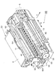
図1は、本発明に係るインクジェット式記録装置の外観斜視図である。図2は、本発明に係るインクジェット式記録装置の本体カバーを取り外した状態の概略斜視図である。図3は、本発明に係るインクジェット式記録装置の内部構造の要部斜視図である。図4は、本発明に係るインクジェット式記録装置の内部構造の要部側断面図である。図5は、インクジェット式記録装置の内部構造の要部斜視図であり、紙案内後部材を取り外した状態を示したものである。 FIG. 1 is an external perspective view of an ink jet recording apparatus according to the present invention. FIG. 2 is a schematic perspective view of the ink jet recording apparatus according to the present invention with the main body cover removed. FIG. 3 is a perspective view of the main part of the internal structure of the ink jet recording apparatus according to the present invention. FIG. 4 is a sectional side view of the main part of the internal structure of the ink jet recording apparatus according to the present invention. FIG. 5 is a perspective view of the main part of the internal structure of the ink jet recording apparatus, and shows a state in which the post-paper guiding member is removed.
インクジェット式記録装置100は、図1に示した如く本体カバー1で覆われており、本体カバー1の上面には、上方向へ開閉可能な上面カバー2が配設されている。上面カバー2を開くことによって、インクジェット式記録装置100の内部へユーザがアクセスすることが可能となり、インクカートリッジの交換等を行うことが可能になる。本体カバー1の前面には、電源スイッチ等のスイッチ類5が配設されているほか、排紙スタッカ3並びにトレイカバー4が前方へ開閉可能に配設されている。排紙スタッカ3は、記録実行時には前方に開いた状態で使用され、記録実行後の「被記録材」及び「被搬送体」としての記録紙Pが開いた状態の排紙スタッカ3の上に排出されて積重されるようになっている。トレイカバー4は、前方に開いた状態でディスクトレイを前方からユーザが手差し挿入するためのトレイ挿入口へのアクセスが可能になる。ディスクトレイは、光記録ディスクのラベル面への記録を実行する際に使用され、光記録ディスクを装着した状態のディスクトレイをトレイ挿入口の所定の挿入位置まで手差し挿入して記録を実行することによって、光記録ディスクのラベル面への記録を実行することができる。
The ink
インクジェット式記録装置100の後部には、図示の如く自動給紙装置20が配設されており、自動給紙装置20の上部には、上方向へ開閉可能な給紙トレイカバー6が配設されている。給紙トレイカバー6は、記録実行時には開いた状態で使用され、開いた状態の給紙トレイカバー6と一体となって記録紙Pの支持面を形成する給紙トレイ22に記録実行前の記録紙Pが積重されるようになっている。給紙トレイ22に積重された記録紙Pは、給紙時に所定のタイミングで給紙ローラ21側へ揺動するホッパ23により給紙ローラ21の外周面に押圧される。給紙ローラ21の外周面に押圧された記録紙Pは、給紙ローラ軸211を回転軸として回転可能に配設されている給紙ローラ21の駆動回転によって、搬送駆動ローラ41の外周面と搬送従動ローラ42の外周面との当接面へ向けて1枚ずつ自動給紙される。
As shown in the figure, an
インクジェット式記録装置100の筐体は、メインフレーム11、左サイドフレーム12、右サイドフレーム13、右サイド外フレーム13a及びリアフレーム19で主たる骨格が形成されている。左サイドフレーム12(部材191を介して)、右サイドフレーム13、及び右サイド外フレーム13aは、インクジェット式記録装置100の前面側においてリアフレーム19で連結されている。搬送駆動ローラ41の両端支持部(左端支持部411と右端支持部412)は、記録紙Pの搬送方向(副走査方向Y)に回転可能な如く左サイドフレーム12と右サイドフレーム13とにそれぞれ回転可能に支持されている。搬送駆動ローラ41の左端支持部411は、回転ブッシュ17を介して左サイドフレーム12に回転可能に支持され、搬送駆動ローラ41の右端支持部412は、回転ブッシュ18を介して右サイドフレーム13に回転可能に支持されている。
The
また、搬送駆動ローラ41の中央近傍に形成されている中央支持部413は、中支え部材15によって回転可能に支持されている。中支え部材15は、サブフレーム14に回動可能に配設されている調整部材16の回動位置によって中央支持部413の支持位置を上下動させることができるようになっている。搬送駆動ローラ41の外周面のうち記録紙Pが押圧されて密着される部分には、中支え部材15によって回転可能に支持される中央支持部413を除いて高摩擦抵抗被膜が形成されている。つまり、図示の如く中央支持部413を挟んで左側に高摩擦抵抗被膜41a、右側に高摩擦抵抗被膜41bがそれぞれ形成されている。
Further, the
各搬送従動ローラホルダ43には、2つの搬送従動ローラ42が記録紙Pの搬送方向へ従動回転可能に支持されており、搬送従動ローラホルダ43は、搬送駆動ローラ41と平行に複数並べて配置され、それぞれメインフレーム11に揺動可能に支持されている。各搬送従動ローラホルダ43は、ばね431によって搬送駆動ローラ41へ押圧付勢されており、それによって、各搬送従動ローラ42は、略一定の押圧力で搬送駆動ローラ41の外周面に押圧されている。また、各搬送従動ローラホルダ43の副走査方向Y下流側には、補助ローラホルダ43Sがそれぞれ配設されており、補助ローラホルダ43Sには、補助ローラ42Sが記録紙Pの搬送方向へ従動回転可能に支持されている。搬送駆動ローラ41の左端支持部411、右端支持部412、及び中央支持部413近傍を除く外周面には、高摩擦抵抗被膜が均一に形成されている。自動給紙装置20から給紙される記録紙Pは、紙案内前部材44により搬送駆動ローラ41の外周面へ向けて案内され、搬送駆動ローラ41の外周面と搬送従動ローラ42との当接面に狭持されて搬送駆動ローラ41の高摩擦抵抗被膜面に押圧されて密着し、搬送駆動ローラ41が副走査方向Yへ回転することによって、搬送駆動ローラ41の回転量に応じた搬送量で副走査方向Yへ搬送される。
Two transport driven
搬送駆動ローラ41は、搬送歯車54が回転伝達可能に一体に取り付けられており、搬送用モータ51の駆動プーリ52の駆動回転が無端ベルト53を介して搬送歯車54へ伝達されて回転する(図3)。搬送駆動ローラ41の回転によって副走査方向Yへ搬送される記録紙Pは、紙案内後部材45と一体に形成されているプラテン46に裏面が摺接しながら面姿勢が規制されつつ搬送される。尚、搬送駆動ローラ41の左端支持部411側には、搬送駆動ローラ41の回転量を検出する「回転量検出手段」として公知のロータリエンコーダが設けられている。ロータリエンコーダは、搬送駆動ローラ41の回転に連動して回転するロータリスケール50(図2)と、ロータリスケール50の外周に沿って等間隔に形成されているスリットを検出するロータリスケールセンサ501(図2)とを有している。
The
インクジェット式記録装置100は、記録紙Pにインクを噴射して記録を行う記録ヘッド63を記録紙Pに対して主走査方向Xに走査させるためのキャリッジ62を備えている。キャリッジ62は、主走査方向Xに往復動可能にキャリッジガイド軸61に軸支されており、図示していないキャリッジ用モータの回転駆動力が図示していないベルト伝達機構によって伝達されて主走査方向Xに往復動する。キャリッジガイド軸61は、左サイドフレーム12と右サイド外フレーム13aとで両端を支持されて配設されている。キャリッジ62には、各色のインクが充填されたインクカートリッジ(図示せず)が着脱可能に搭載され、インクカートリッジから記録ヘッド63へ各色のインクが供給される。記録ヘッド63のヘッド面は、プラテン46と対向する位置で主走査方向Xへ往復動し、ヘッド面に多数配置されているノズルからプラテン46上を搬送される記録紙Pへインクが噴射されて記録が実行される。記録ヘッド63のヘッド面と記録紙Pの記録面との間隔は、プラテン46によって規定される。
The ink
また、インクジェット式記録装置100には、キャリッジ62の移動位置を検出するための公知のリニアエンコーダが配設されている。リニアエンコーダは、キャリッジガイド軸61と平行に配設されたリニアスケール64(図2)と、キャリッジ62に搭載され、リニアスケール64に等間隔に形成されているスリットを検出するリニアスケールセンサ(図示せず)とを有している。
The ink
一方、プラテン46より副走査方向Yの下流側には、記録実行後の記録紙Pを排紙する手段として、副走査方向Yへ回転可能に紙案内後部材45に回転可能に支持された第1の排紙駆動ローラ軸47及び第2の排紙駆動ローラ軸48が配設されている。第1の排紙駆動ローラ軸47には、図示の如く複数の第1の排紙駆動ローラ471が略等間隔に設けられており、第2の排紙駆動ローラ軸48にも同様に複数の第2の排紙駆動ローラ481が略等間隔に設けられている。第2の排紙駆動ローラ481は、搬送歯車54、中間歯車55及び排紙歯車56を介して搬送用モータ51の回転駆動力が第2の排紙駆動ローラ軸48へ伝達されて排出方向(副走査方向Y)に回転する。第1の排紙駆動ローラ471は、第2の排紙駆動ローラ軸48に回転伝達可能に取り付けられている歯車57及び図示していない中間歯車を介して、第1の排紙駆動ローラ軸47に回転伝達可能に取り付けられている歯車58へ搬送用モータ51の回転駆動力が伝達されて排出方向(副走査方向Y)に回転する。
On the other hand, on the downstream side of the
第1の排紙駆動ローラ軸47及び第2の排紙駆動ローラ軸48の上側には、主走査方向Xに長尺な排紙フレーム49(図4)が設けられている。排紙フレーム49には、第1の排紙駆動ローラ471に対応する位置に複数の第1の排紙従動ローラ472が従動回転可能に支持されており、第2の排紙駆動ローラ481に対応する位置に複数の第2の排紙従動ローラ482が従動回転可能に支持されている。第1の排紙従動ローラ472及び第2の排紙従動ローラ482は、周囲に複数の歯を有し、各歯の先端が記録紙Pの記録面に点接触するように鋭角的に尖っている歯付きローラになっており、それぞれ第1の排紙駆動ローラ471及び第2の排紙駆動ローラ481に弱い付勢力で付勢されている。記録実行後の記録紙Pは、第1の排紙駆動ローラ471と第1の排紙従動ローラ472との間に狭持されて、第1の排紙駆動ローラ471の排出方向への回転によって搬送され、さらに、第2の排紙駆動ローラ481と第2の排紙従動ローラ482との間に狭持されて、第2の排紙駆動ローラ481の排出方向への回転によって、開いた状態の排紙スタッカ3へと排出される。
A paper discharge frame 49 (FIG. 4) that is long in the main scanning direction X is provided above the first paper discharge
このような構成を有するインクジェット式記録装置100は、まず、記録前の白紙の記録紙Pが自動給紙装置20によって自動給紙される。つづいて、自動給紙された記録前の白紙の記録紙Pは、搬送駆動ローラ41の回転によって記録ヘッド63のヘッド面と対向するプラテン46に摺接しながら副走査方向Yへ所定の搬送量で搬送される動作と、プラテン46の上で主走査方向Xへ往復動する記録ヘッド63からインクが噴射される動作とが交互に繰り返し実行されて記録面への記録が実行される。そして、記録実行後の記録紙Pは、第1の排紙駆動ローラ471及び第2の排紙駆動ローラ472の排出方向への回転によって排紙スタッカ3へ排出される。これらの一連の記録実行動作は、図示していない記録制御装置によって、自動給紙装置20の駆動力源としての自動給紙用モータ(図示せず)、搬送用モータ51並びにキャリッジ駆動用モータ(図示せず)が制御されて実行される。
In the ink
つづいて、本発明に係る「搬送装置」について説明する。
図6は、搬送駆動ローラ41の中央支持部413近傍を拡大した要部斜視図である。図7は、搬送駆動ローラ41の中央支持部413近傍を前面から見た要部正面図である。図8は、搬送駆動ローラ41の中央支持部413近傍を裏面から見た要部正面図である。
本発明に係る「搬送装置」は、搬送駆動ローラ41と、搬送駆動ローラ41の外周面に記録紙Pを押圧する「被搬送体押圧手段」としての搬送従動ローラホルダ43(図6〜図8においては図示省略)と、搬送従動ローラホルダ43による記録紙Pの押圧力に対向する如く搬送駆動ローラ41の中央支持部413を記録紙Pの搬送経路外で摺接支持する「中支え手段」とで構成されている。「中支え手段」は、搬送駆動ローラ41の中央支持部413を記録紙Pの搬送経路外で摺接支持する中支え部材15と、中支え部材15による中央支持部413の摺接支持位置を搬送駆動ローラ41の回転軸と略直交する方向へ変位調節(上下動調節)可能に配設された「支持位置調節手段」としての調整部材16とを有している。
Next, the “conveying device” according to the present invention will be described.
FIG. 6 is an enlarged perspective view of a main part in the vicinity of the
The “conveying device” according to the present invention includes a
搬送駆動ローラ41は、中央支持部413において、中央支持部413の外周面に中支え部材15の摺接支持面151が図示の如く摺接した状態で回転可能に支持される。中支え部材15は、搬送駆動ローラ41の軸心に対する湾曲変形により生じる搬送駆動ローラ41が回転した際の回転軸と直交する方向の外周面の変動を規制すべく、中央支持部413の摺接支持面151が搬送駆動ローラ41の外周面の変動規制面となる位置に配置される。摺接支持面151は、図示の如く中央支持部413の外周面に沿って摺接する内周面を有する形状を成しており、搬送従動ローラホルダ43による記録紙Pの押圧方向(上下方向)及び該押圧方向と略直交する方向(前後方向)の搬送駆動ローラ41の外周面変動を規制可能な形状を有している。それによって、搬送駆動ローラ41の回転中の「縄跳び現象」を効果的に防止することができる。
The
中支え部材15は、搬送従動ローラホルダ43による記録紙Pの押圧力に対向する如く底部154側が調整部材16の偏心カム166の外周面に当接支持されてサブフレーム14に配設されている。調整部材16は、符号Aで示した方向に回動可能にサブフレーム14に支持されており、その回動位置に応じて中支え部材15が符号Bで示した方向へ上下動して搬送駆動ローラ41の中央支持部413の支持位置を調整することができるようになっている。調整部材16は、回動軌跡に沿った形状を有する孔164の外側に形成された歯部165が孔164により生じる弾性を有して回動位置決め凸部144にクリック係合している。調整部材16の回動位置は、歯部165の歯の間隔で位置決めされ、回動軌跡に沿った形状を有する孔163に挿通された状態でサブフレーム14に螺嵌されているネジ143を締め付けることによって、調整後の最適な回動位置で固定することができるようになっている。
The
つづいて、本発明に係る搬送駆動ローラ41について説明する。
図9は、搬送駆動ローラ41の支持状態を模式的に示した正面図である。
本発明に係る搬送駆動ローラ41は、「両端支持部」としての左端支持部411及び右端支持部412にて支持された状態で、各搬送従動ローラホルダ43に回転可能に支持された各搬送従動ローラ42の押圧力により撓ませることが可能な可撓性を有している。ここで、搬送駆動ローラ41の軸長をL、搬送駆動ローラ41の軸径をD、各搬送従動ローラ42により搬送駆動ローラ41の外周面に作用する押圧荷重をF、搬送駆動ローラ41の重量をW、搬送駆動ローラ41のヤング率をEとする。そして、搬送駆動ローラ41の湾曲変形量をδ、押圧荷重F及び重量Wによる搬送駆動ローラ41の最大撓み量をδmaxとすると、搬送駆動ローラ41の軸長L及び軸径Dは、δ<δmax(L,D,F,W,E)なる関係式を満たす設定となっている。
Next, the
FIG. 9 is a front view schematically showing the support state of the
The
例えば、図9に示した如く8個の搬送従動ローラ42が搬送駆動ローラ41の回転軸に沿って略等間隔に配置されているとする。各搬送従動ローラ42の荷重をPn、搬送駆動ローラ41の一端側(左端支持部411)の支持位置から各搬送従動ローラ42までの距離をbnとし、搬送駆動ローラ41の断面2次モーメントをIとすると、最大撓み量δmax及び断面2次モーメントIは、図9に示した各式によって近似されることになる。したがって、図9に示した最大撓み量δmax及び断面2次モーメントIの近似式に基づいて、δ<δmaxとなるように、搬送駆動ローラ41の軸長L及び軸径Dを設定する。それによって、搬送駆動ローラ41は、各搬送従動ローラホルダ43に回転可能に支持された各搬送従動ローラ42の押圧力により撓ませることが可能な可撓性を有することになる。
For example, as shown in FIG. 9, it is assumed that eight conveyance driven
前述したように、中支え部材15は、搬送駆動ローラ41の軸心に対する湾曲変形により生じる搬送駆動ローラ41が回転した際の回転軸と直交する方向の外周面の変動を規制すべく、中央支持部413の摺接支持面が搬送駆動ローラ41の外周面の変動規制面となる位置に配置される。したがって、押圧荷重F及び搬送駆動ローラ41の重量Wで中央支持部413が中支え部材15の摺接支持面151へ押圧された状態で搬送駆動ローラ41が回転可能に支持することによって、搬送駆動ローラ41が軸心に対して湾曲変形していることによって回転中に生じる搬送駆動ローラ41の外周面の変動を規制することが可能になり、搬送駆動ローラ41の回転中における「縄跳び現象」を防止することができる。
As described above, the
このように、搬送駆動ローラ41の回転中における「縄跳び現象」を防止することによって、記録紙Pの搬送精度が向上させることができる。また、搬送駆動ローラ41に上述した可撓性を持たせることによって、搬送駆動ローラ41の軸径が従来よりも小さくなるので、インクジェット式記録装置100の小型化及び軽量化が可能になるとともに、搬送駆動ローラ41の部品コストを低減させることができる。さらに、搬送駆動ローラ41の軸径が従来よりも小さくなることによって、中支え部材15の摺接支持面151における回転摩擦抵抗が少なくなり、それによって搬送駆動ローラ41の軸損負荷が低減され、搬送駆動ローラ41の回転駆動力源となるモータ等を小型化することができる。さらに、搬送駆動ローラ41の軸心に対する湾曲変形を矯正しつつ回転させるので、搬送駆動ローラ41の湾曲変形量がある程度の範囲内であれば記録紙Pの搬送精度に影響しないため、搬送駆動ローラ41を低い製造コストで量産することができる。
In this way, by preventing the “jumping phenomenon” during the rotation of the
本発明に係る「搬送装置」は、さらに、前述した紙案内前部材44及び紙案内後部材45を含んで構成されており、以下さらに説明する。
The “conveying apparatus” according to the present invention further includes the above-described
図10は、紙案内前部材44の周辺を示した要部斜視図である。図11は、紙案内後部材45の周辺を示した要部斜視図である。
「給送案内部材」としての紙案内前部材44は、搬送駆動ローラ41の回転軸と略平行に形成され、自動給紙装置20から給紙される記録紙Pを搬送駆動ローラ41の外周面の適正な位置に適正な姿勢で当接させる如く案内する給送案内面444を有している。給送案内面444には、図示の如く多数のリブが形成されている。紙案内前部材44は、搬送駆動ローラ41の回転軸方向の一端側に形成された腕部441が搬送駆動ローラ41の左端支持部411近傍(高摩擦抵抗被膜41aの外側)に掛着して支持されている。
FIG. 10 is a perspective view of the main part showing the periphery of the paper guiding
A paper
一方、搬送駆動ローラ41の回転軸方向の他端側に形成された腕部442が搬送駆動ローラ41の右端支持部412近傍(高摩擦抵抗被膜41bの外側)に回転ブッシュ18を介して掛着して支持されている。搬送駆動ローラ41が回転する際には、左端支持部411近傍が腕部441の内周面に摺接して回転し、右端支持部412近傍は回転ブッシュ18に支持されて回転する。したがって、紙案内前部材44は、搬送駆動ローラ41が回転可能な状態で搬送駆動ローラ41の両端部近傍に支持されることになる。そして、紙案内前部材44は、搬送駆動ローラ41の両端部近傍に支持された状態で、搬送駆動ローラ41の外周面と紙案内前部材44の給送案内面444との位置関係が最適になるように、つまり、自動給紙装置20から給紙される記録紙Pが搬送駆動ローラ41の外周面の適正な位置に適正な姿勢で当接させる如く案内される位置関係となるように形成されている。
On the other hand, an
一方、「搬送案内部材」としての紙案内後部材45は、搬送駆動ローラ41の回転軸と略平行に形成され、搬送駆動ローラ41の回転によって搬送される記録紙Pを所定の搬送経路へ案内する「搬送案内面」としてのプラテン46を有している。プラテン46には、図示の如く多数のリブが形成されており、リブの頂部に記録紙Pの裏面(記録面と反対側の面)が摺接した状態で記録紙Pが副走査方向Yへ搬送されることによって、プラテン46の上を主走査方向Xへ往復動する記録ヘッド63のヘッド面との間隔が高精度に規定されるようになっている。紙案内後部材45は、搬送駆動ローラ41の回転軸方向の一端側に形成された腕部451が搬送駆動ローラ41の左端支持部411近傍(高摩擦抵抗被膜41aの外側)に掛着して支持されている。
On the other hand, the
一方、紙案内後部材45は、搬送駆動ローラ41の回転軸方向の他端側端部452が回転ブッシュ18を支持している左サイドフレーム13に係合して支持されている。搬送駆動ローラ41が回転する際には、左端支持部411近傍が腕部451の内周面に摺接して回転し、右端支持部412近傍は回転ブッシュ18に支持されて回転する。したがって、紙案内後部材45は、紙案内前部材44と同様に、搬送駆動ローラ41が回転可能な状態で搬送駆動ローラ41の両端部近傍に支持されることになる。そして、紙案内後部材45は、搬送駆動ローラ41の両端部近傍に支持された状態で、プラテン46に摺接しながら副走査方向Yへ搬送される記録紙Pの記録面と、記録ヘッド63のヘッド面との間隔が高精度に規定されるように形成されている。
On the other hand, the
図12は、中支え部材15の近傍の断面を拡大して示した斜視図である。図13は、中支え部材15の近傍の断面を拡大して示した側面図である。
紙案内前部材44は、中央近傍に形成されている凸部443が中支え部材15の対応する位置に形成されている2つの凸部152の間に嵌合した状態で中支え部材15と連結されて支持される。一方、紙案内後部材45は、中央近傍に形成されている凸部453が中支え部材15の対応する位置に形成されている凹部153に嵌合した状態で中支え部材15と連結されて支持される。紙案内前部材44は、調整部材16を符号Aで示した方向へ回動させることによる中支え部材15の上下方向(符号Bで示した方向)の変位に連動して、搬送駆動ローラ41の外周面と給送案内面444との間隔が略均等になる如く、給送案内面444の中央近傍が上下方向(符号Bで示した方向)に撓み変形する。同様に、紙案内後部材45も調整部材16による中支え部材15の変位に連動して、搬送駆動ローラ41の外周面とプラテン46との間隔が略均等になる如く、プラテン46の中央近傍が上下方向(符号Bで示した方向)に撓み変形する。
FIG. 12 is an enlarged perspective view showing a cross section in the vicinity of the
The paper guide
紙案内前部材44の給送案内面444に反りや湾曲変形が生じてしまっていても、搬送駆動ローラ41の外周面と給送案内面444との間隔が略均等に維持されて給送案内面444の反りや湾曲変形を矯正することができる。それによって、記録紙Pの幅方向(主走査方向X)の全幅に亘って、搬送駆動ローラ41の外周面に対する記録紙Pの先端の突き当て位置及び突き当て角度等を略均一にすることができるので、給送案内面444の反りや湾曲変形に起因する記録紙Pのスキューや記録紙Pの撓み、浮き上がり、先端折れ、頭出し量のばらつき等を防止することができる。
同様に、紙案内後部材45のプラテン46に反りや湾曲変形が生じてしまっていても、搬送駆動ローラ41の外周面とプラテン46との間隔が略均等に維持されてプラテン46の反りや湾曲変形を矯正することができる。それによって、記録紙Pの幅方向の全幅に亘って、搬送駆動ローラ41の外周面に対するプラテン46に摺接して搬送される記録紙Pの姿勢及び記録紙Pの摺接角度等を略均一にすることができるので、プラテン46の反りや湾曲変形に起因する記録紙Pのスキューや記録紙Pの撓み、浮き上がり等を防止することができる。
Even if the
Similarly, even if the
尚、本発明は上記実施例に限定されることなく、特許請求の範囲に記載した発明の範囲内で、種々の変形が可能であり、それらも本発明の範囲内に含まれるものであることは言うまでもない。 The present invention is not limited to the above-described embodiments, and various modifications can be made within the scope of the invention described in the claims, and these are also included in the scope of the present invention. Needless to say.
1 本体カバー、2 上面カバー、3 排紙スタッカ、4 トレイカバー、5 スイッチ類、6 給紙トレイカバー、14 サブフレーム、15 中支え部材、16 調整部材、20 自動給紙装置、21 給紙ローラ、22 給紙トレイ、23 ホッパ、41 搬送駆動ローラ、42 搬送従動ローラ、43 搬送従動ローラホルダ、44 紙案内前部材、45 紙案内後部材、46 プラテン、47 第1の排紙駆動ローラ軸、48 第2の排紙駆動ローラ軸、51 搬送用モータ、61 キャリッジガイド軸、62 キャリッジ、63 記録ヘッド、100 インクジェット式記録装置、411 左端支持部、412 右端支持部、413 中央支持部、444 給送案内面、41a、41b 高摩擦抵抗被膜
DESCRIPTION OF
Claims (9)
前記中支え手段による前記中央支持部の摺接支持位置を前記搬送駆動ローラの回転軸と略直交する方向へ変位調節可能な支持位置調節手段と、
被搬送体の給送手段から給送される被搬送体を前記搬送駆動ローラの外周面へ案内する給送案内面を有する給送案内部材とを備え、
前記支持位置調節手段による前記中支え手段の変位に連動して前記給送案内面が変位する、ことを特徴とした搬送装置。 A conveyance drive roller that is rotatably supported at both end support portions and a central support portion and is rotated by a rotation driving force transmitted by a driving force source, and the central support portion of the conveyance drive roller outside the conveyance path of the conveyance target An intermediate support means for slidingly supporting, and by rotating the transport driving roller with the rotational driving force of the driving force source, the transported body in contact with the outer peripheral surface of the transport driving roller has a predetermined transport direction. A transport device transported to
A support position adjusting means capable of adjusting a displacement of the sliding contact support position of the central support portion by the intermediate support means in a direction substantially perpendicular to the rotation axis of the transport drive roller;
And a feeding guide member having a feeding guide surfaces you the draft to the outer peripheral surface of the transport driving roller conveyance object fed from the feeding means of the carrier,
Before Symbol supporting position the feeding guide surface in conjunction with the displacement in said support means by the adjustment means for displacement of the conveying apparatus, characterized in that.
前記中支え手段による前記中央支持部の摺接支持位置を前記搬送駆動ローラの回転軸と略直交する方向へ変位調節可能な支持位置調節手段と、
被搬送体の給送手段から給送される被搬送体を前記搬送駆動ローラの外周面の適正な位置に適正な姿勢で当接させる如く案内する前記搬送駆動ローラの回転軸と略平行な給送案内面を有する給送案内部材とを備え、
前記搬送駆動ローラの外周面と前記給送案内面との間隔が略均等になる如く、前記支持位置調節手段による前記中支え手段の変位に連動して前記給送案内面が少なくとも一部変位する、ことを特徴とした搬送装置。 A conveyance drive roller that is rotatably supported at both end support portions and a central support portion and is rotated by a rotation driving force transmitted by a driving force source, and the central support portion of the conveyance drive roller outside the conveyance path of the conveyance target An intermediate support means for slidingly supporting, and by rotating the transport driving roller with the rotational driving force of the driving force source, the transported body in contact with the outer peripheral surface of the transport driving roller has a predetermined transport direction. A transport device transported to
A support position adjusting means capable of adjusting a displacement of the sliding contact support position of the central support portion by the intermediate support means in a direction substantially perpendicular to the rotation axis of the transport drive roller;
Feeding substantially parallel to the rotation axis of the transport drive roller that guides the transported body fed from the feeding means of the transported body so as to contact the proper position of the outer peripheral surface of the transport driving roller in an appropriate posture. A feeding guide member having a feeding guide surface,
The feed guide surface is displaced at least partially in conjunction with the displacement of the intermediate support means by the support position adjusting means so that the distance between the outer peripheral surface of the transport drive roller and the feed guide surface is substantially equal. A conveying device characterized by that.
前記搬送駆動ローラの外周面と前記搬送案内面との間隔が略均等になる如く、前記支持位置調節手段による前記中支え手段の変位に連動して前記搬送案内面が撓み変形する、ことを特徴とした搬送装置。 4. The conveyance according to claim 1, further comprising a conveyance guide surface substantially parallel to a rotation axis of the conveyance drive roller that guides a conveyance object conveyed by the rotation of the conveyance drive roller to a predetermined conveyance path. Comprising a guide member,
The conveyance guide surface is bent and deformed in conjunction with the displacement of the intermediate support means by the support position adjusting means so that the distance between the outer peripheral surface of the conveyance drive roller and the conveyance guide surface becomes substantially equal. The transfer device.
前記中支え手段による前記中央支持部の摺接支持位置を前記搬送駆動ローラの回転軸と略直交する方向へ変位調節可能な支持位置調節手段と、
前記搬送駆動ローラの回転によって搬送される被搬送体を所定の搬送経路へ案内する前記搬送駆動ローラの回転軸と略平行な搬送案内面を有する搬送案内部材とを備え、
前記搬送駆動ローラの外周面と前記搬送案内面との間隔が略均等になる如く、前記支持位置調節手段による前記中支え手段の変位に連動して前記搬送案内面が少なくとも一部変位する、ことを特徴とした搬送装置。 A conveyance drive roller that is rotatably supported at both end support portions and a central support portion and is rotated by a rotation driving force transmitted by a driving force source, and the central support portion of the conveyance drive roller outside the conveyance path of the conveyance target An intermediate support means for slidingly supporting, and by rotating the transport driving roller with the rotational driving force of the driving force source, the transported body in contact with the outer peripheral surface of the transport driving roller has a predetermined transport direction. A transport device transported to
A support position adjusting means capable of adjusting a displacement of the sliding contact support position of the central support portion by the intermediate support means in a direction substantially perpendicular to the rotation axis of the transport drive roller;
A conveyance guide member having a conveyance guide surface substantially parallel to a rotation axis of the conveyance drive roller for guiding a conveyance object conveyed by the rotation of the conveyance drive roller to a predetermined conveyance path;
The conveyance guide surface is displaced at least partially in conjunction with the displacement of the intermediate support means by the support position adjusting means so that the distance between the outer peripheral surface of the conveyance drive roller and the conveyance guide surface is substantially uniform. Conveying device characterized by
前記中支え手段は、前記被搬送体押圧手段による被搬送体の押圧力に対向する如く前記搬送駆動ローラの前記中央支持部を摺接支持する構成を有し、
前記搬送駆動ローラは、前記両端支持部にて回転可能に支持された状態で前記被搬送体押圧手段の押圧力により撓ませることが可能な可撓性を有し、
前記中支え手段は、前記搬送駆動ローラの軸心に対する湾曲変形により生じる前記搬送駆動ローラが回転した際の回転軸と直交する方向の外周面の変動を規制すべく、前記搬送駆動ローラの摺接支持面が前記搬送駆動ローラの外周面の変動規制面となる位置に配置される、ことを特徴とした搬送装置。 In any one of claims 1 to 7 comprising a conveyance object pressing means for pressing the conveyed object on the outer circumferential surface of the transport driving roller,
The intermediate support means has a configuration for slidingly supporting the central support portion of the transport driving roller so as to face the pressing force of the transported body by the transported body pressing means,
The transport driving roller has flexibility capable of being bent by the pressing force of the transported body pressing means in a state of being rotatably supported by the both end support portions,
The intermediate support means is configured to slidably contact the transport drive roller so as to regulate a change in an outer peripheral surface in a direction perpendicular to the rotation axis when the transport drive roller rotates due to a bending deformation with respect to an axis of the transport drive roller. 2. A transport apparatus according to claim 1, wherein the support surface is disposed at a position to be a fluctuation regulating surface of the outer peripheral surface of the transport drive roller.
Priority Applications (1)
| Application Number | Priority Date | Filing Date | Title |
|---|---|---|---|
| JP2004270473A JP4400387B2 (en) | 2004-09-16 | 2004-09-16 | Conveying apparatus and recording apparatus provided with the conveying apparatus |
Applications Claiming Priority (1)
| Application Number | Priority Date | Filing Date | Title |
|---|---|---|---|
| JP2004270473A JP4400387B2 (en) | 2004-09-16 | 2004-09-16 | Conveying apparatus and recording apparatus provided with the conveying apparatus |
Publications (3)
| Publication Number | Publication Date |
|---|---|
| JP2006082940A JP2006082940A (en) | 2006-03-30 |
| JP2006082940A5 JP2006082940A5 (en) | 2007-10-25 |
| JP4400387B2 true JP4400387B2 (en) | 2010-01-20 |
Family
ID=36161764
Family Applications (1)
| Application Number | Title | Priority Date | Filing Date |
|---|---|---|---|
| JP2004270473A Expired - Fee Related JP4400387B2 (en) | 2004-09-16 | 2004-09-16 | Conveying apparatus and recording apparatus provided with the conveying apparatus |
Country Status (1)
| Country | Link |
|---|---|
| JP (1) | JP4400387B2 (en) |
Families Citing this family (3)
| Publication number | Priority date | Publication date | Assignee | Title |
|---|---|---|---|---|
| US7621529B2 (en) | 2006-11-30 | 2009-11-24 | Seiko Epson Corporation | Printing medium feeding device, printing apparatus, and liquid ejecting apparatus |
| JP4892389B2 (en) | 2007-04-03 | 2012-03-07 | 株式会社ミマキエンジニアリング | Printer device |
| JP6863201B2 (en) * | 2017-09-25 | 2021-04-21 | 沖電気工業株式会社 | Media processing equipment and automated teller machines |
-
2004
- 2004-09-16 JP JP2004270473A patent/JP4400387B2/en not_active Expired - Fee Related
Also Published As
| Publication number | Publication date |
|---|---|
| JP2006082940A (en) | 2006-03-30 |
Similar Documents
| Publication | Publication Date | Title |
|---|---|---|
| EP2116383B1 (en) | Conveying apparatus and recording apparatus | |
| JP5023941B2 (en) | Recording medium feeding apparatus, recording apparatus, and liquid ejecting apparatus | |
| US6129461A (en) | Image recording apparatus having adjustment structure | |
| JP4401934B2 (en) | Recording apparatus and control method thereof | |
| JP2004009699A (en) | Recording medium conveyance tray | |
| JP3762228B2 (en) | Recording apparatus and recording method | |
| JP2006281762A (en) | Platen, recorder, and liquid injection apparatus | |
| JP5060603B2 (en) | Recording medium guide apparatus, recording apparatus, and liquid ejecting apparatus | |
| JP4400387B2 (en) | Conveying apparatus and recording apparatus provided with the conveying apparatus | |
| JP4232047B2 (en) | Feeding device for transported body and image recording apparatus having the same | |
| JP4497311B2 (en) | Recording device | |
| JP2006036483A (en) | Image recording device | |
| JP2006082439A (en) | Carrying device, and recording device equipped with the carrying device | |
| JP7318435B2 (en) | image recorder | |
| JP2002226077A (en) | Recording device and recording method | |
| JP2007083500A (en) | Recording apparatus | |
| US7210678B2 (en) | Sheet conveying device | |
| JP4412481B2 (en) | Method for manufacturing conveyance drive roller, conveyance drive roller | |
| JP2005280213A (en) | Device for guiding medium to be recorded, recorder and liquid ejector | |
| JPH10250184A (en) | Recorder | |
| JP4484055B2 (en) | Conveying apparatus and image recording apparatus provided with the same | |
| JP2004268338A (en) | Liquid injection device | |
| JP3548554B2 (en) | Recording device | |
| JP2006089221A (en) | Automatic feeder, and recording device provided with the same | |
| JP2004268336A (en) | Carriage and liquid ejector equipped with that carriage |
Legal Events
| Date | Code | Title | Description |
|---|---|---|---|
| A521 | Written amendment |
Free format text: JAPANESE INTERMEDIATE CODE: A523 Effective date: 20070911 |
|
| A621 | Written request for application examination |
Free format text: JAPANESE INTERMEDIATE CODE: A621 Effective date: 20070911 |
|
| RD04 | Notification of resignation of power of attorney |
Free format text: JAPANESE INTERMEDIATE CODE: A7424 Effective date: 20090622 |
|
| A977 | Report on retrieval |
Free format text: JAPANESE INTERMEDIATE CODE: A971007 Effective date: 20090630 |
|
| RD03 | Notification of appointment of power of attorney |
Free format text: JAPANESE INTERMEDIATE CODE: A7423 Effective date: 20090706 |
|
| TRDD | Decision of grant or rejection written | ||
| A01 | Written decision to grant a patent or to grant a registration (utility model) |
Free format text: JAPANESE INTERMEDIATE CODE: A01 Effective date: 20091006 |
|
| A01 | Written decision to grant a patent or to grant a registration (utility model) |
Free format text: JAPANESE INTERMEDIATE CODE: A01 |
|
| R150 | Certificate of patent or registration of utility model |
Ref document number: 4400387 Country of ref document: JP Free format text: JAPANESE INTERMEDIATE CODE: R150 Free format text: JAPANESE INTERMEDIATE CODE: R150 |
|
| A61 | First payment of annual fees (during grant procedure) |
Free format text: JAPANESE INTERMEDIATE CODE: A61 Effective date: 20091019 |
|
| FPAY | Renewal fee payment (event date is renewal date of database) |
Free format text: PAYMENT UNTIL: 20121106 Year of fee payment: 3 |
|
| FPAY | Renewal fee payment (event date is renewal date of database) |
Free format text: PAYMENT UNTIL: 20121106 Year of fee payment: 3 |
|
| FPAY | Renewal fee payment (event date is renewal date of database) |
Free format text: PAYMENT UNTIL: 20131106 Year of fee payment: 4 |
|
| S531 | Written request for registration of change of domicile |
Free format text: JAPANESE INTERMEDIATE CODE: R313531 |
|
| R350 | Written notification of registration of transfer |
Free format text: JAPANESE INTERMEDIATE CODE: R350 |
|
| LAPS | Cancellation because of no payment of annual fees |