JP4399738B2 - Goods storage equipment - Google Patents
Goods storage equipment Download PDFInfo
- Publication number
- JP4399738B2 JP4399738B2 JP2005169517A JP2005169517A JP4399738B2 JP 4399738 B2 JP4399738 B2 JP 4399738B2 JP 2005169517 A JP2005169517 A JP 2005169517A JP 2005169517 A JP2005169517 A JP 2005169517A JP 4399738 B2 JP4399738 B2 JP 4399738B2
- Authority
- JP
- Japan
- Prior art keywords
- article
- storage
- protrusion
- traveling
- target
- Prior art date
- Legal status (The legal status is an assumption and is not a legal conclusion. Google has not performed a legal analysis and makes no representation as to the accuracy of the status listed.)
- Expired - Fee Related
Links
Images


Landscapes
- Warehouses Or Storage Devices (AREA)
Description
本発明は、平面視形状が矩形状の物品を対向する一対の辺の長手方向を奥行き方向に沿わせた状態で収納する複数の収納部が横幅方向に並設された収納棚と、
その収納棚の前面側において前記収納部の並び方向に移動操作される移動基台と、
その移動基台に装備されて、平面視形状が矩形状の物品を対向する一対の辺の長手方向を前記収納部の奥行き方向に沿わせた状態で保持する物品保持部が前記移動基台側に引退させた引退位置と前記収納部内に突入させるための突出位置とに亘って出退移動操作される移載装置と、
前記移動基台の前記収納棚に対する前記収納部の並び方向での位置を検出する位置検出手段と、
前記移動基台の移動及び前記移載装置における前記保持部の出退作動を制御する運転制御手段とが設けられ、
前記運転制御手段が、前記複数の収納部のうちで移載作業対象とする収納部が指示されると、前記位置検出手段の検出情報に基づいて、移載作業対象とする収納部に対する目標停止位置に前記移動基台を移動させる移動制御、及び、その移動基台が目標停止位置に停止する前の突出開始位置に移動すると、前記移載装置における保持部を引退位置から突出位置に向けて突出作動させることを開始して突出位置に突出させる早め突出制御を実行するように構成されている物品収納設備に関する。
The present invention is a storage shelf in which a plurality of storage units that store a pair of sides facing the article having a rectangular shape in plan view along the depth direction are arranged in parallel in the width direction;
A movable base that is operated to move in the direction in which the storage units are arranged on the front side of the storage shelf;
An article holding part that is mounted on the moving base and holds the article having a rectangular shape in plan view in a state where the longitudinal direction of a pair of sides facing each other is along the depth direction of the storage part is on the moving base side A transfer device that is operated to move out and retract across a retired position that has been retired and a projecting position for rushing into the storage unit;
Position detecting means for detecting the position of the storage unit in the direction in which the storage units are arranged with respect to the storage shelf;
An operation control means for controlling the movement of the moving base and the moving operation of the holding unit in the transfer device; and
When the operation control means is directed to a storage section to be transferred among the plurality of storage sections, the target stop for the storage section to be transferred is based on the detection information of the position detection means. When the movement base moves to the position, and the movement base moves to the protruding start position before stopping at the target stop position, the holding unit in the transfer device is moved from the retracted position toward the protruding position. The present invention relates to an article storage facility configured to execute early protrusion control to start protrusion operation and to protrude to a protrusion position.
上記物品収納設備は、移動基台が目標停止位置に停止する前の突出開始位置に移動すると、移載装置における保持部を引退位置から突出位置に向けて突出作動させることを開始して突出位置に突出させる早め突出制御を実行することにより、移動基台が目標停止位置に停止後に、移載装置における保持部を引退位置から突出位置に向けて突出作動させることを開始して突出位置に突出させるようにするのに比べて、移動基台が目標停止位置に停止したときから移載装置の保持部が突出位置に突出されるまでに要する時間を短縮させることにより、物品の入出庫作業を能率良く行えるようにしたものである(例えば、特許文献1参照。)
ちなみに、特許文献1においては、収納部が上下左右に備えられた収納棚の前面側の作業通路を走行するスタッカークレーンが備えられるものであって、そのスタッカークレーンに昇降操作自在に装備された昇降台が、収納部の並び方向として、上下方向及び左右方向に移動操作される移動基台として機能するものであり、昇降台に装備した伸縮式のフォーク装置が、物品保持部としての先端側部分を昇降台側に引退させた引退位置と収納部内に突入させるための突出位置とに亘って出退移動させる移載装置として機能することになる。
そして、早め突出制御として、スタッカークレーンが目標停止位置としての目標走行位置に停止する前の突出開始位置に移動(走行)すると、物品保持部としての先端側部分を引退位置から突出位置に向けて突出作動を開始することや、昇降台が目標停止位置としての目標昇降位置に停止する前の突出開始位置に移動(昇降)すると、物品保持部としての先端側部分を引退位置から突出位置に向けて突出作動を開始することが行われるようになっている。又、早め突出制御における突出開始位置は、突出作動を開始した移載装置の物品保持部が棚に干渉することなく突出位置に連続して移動できるようにすることを考慮して、移動基台の目標停止位置から設定距離を離れた一定位置に設定されるようになっている。
When the article storage facility moves to the projecting start position before the moving base stops at the target stop position, it starts to project the holding unit in the transfer device from the retracted position toward the projecting position, and the projecting position After the moving base is stopped at the target stop position, the holding unit in the transfer device starts to project from the retracted position to the projecting position and projects to the projecting position. Compared to making the moving base stand at the target stop position, by shortening the time required for the holding part of the transfer device to be protruded to the protruding position, it is possible to carry out the goods loading / unloading work. This can be performed efficiently (for example, see Patent Document 1).
Incidentally, in
Then, as early protrusion control, when the stacker crane moves (runs) to the protrusion start position before stopping at the target travel position as the target stop position, the tip side portion as the article holding portion is directed from the retraction position to the protrusion position. When the protrusion operation is started or when the lifting platform is moved (lifted / lowered) to the protrusion start position before stopping at the target lift position as the target stop position, the tip side portion as the article holding portion is directed from the retraction position to the protrusion position. Thus, the projecting operation is started. Further, the protrusion start position in the early protrusion control is a moving base considering that the article holding part of the transfer device that has started the protrusion operation can continuously move to the protrusion position without interfering with the shelf. It is set to a fixed position that is a set distance away from the target stop position.
さらに、突出開始位置が前記目標停止位置から遠ければ遠いほど、フォーク装置の突出作動が開始されてから目標停止位置に移動するまでの時間が長くなるので、その分、昇降台が目標停止位置に移動するまでにフォーク装置の突出作動を進行させることができる。したがって、早め突出制御においては、前記目標停止位置からできるだけ遠い位置を突出開始位置として設定することが求められる。 Furthermore, the farther the protrusion start position is from the target stop position, the longer the time from the start of the protrusion operation of the fork device to the movement to the target stop position. The projecting operation of the fork device can be advanced before moving. Therefore, in the early protrusion control, it is required to set a position as far as possible from the target stop position as the protrusion start position.
しかしながら、上述した物品収納設備においては、指示された収納部へ物品を収納するような卸し処理を行う場合に、例えば、フォーク装置の保持部により保持された物品が矩形状であると、この物品の収納部の横幅方向についての移動方向下手側でかつ収納部側の角部が、当該収納部の横幅方向で同下手側の端部より目標停止位置側に位置する状態でなければ、収納しようとする物品の前記角部が、当該収納部の横幅方向で同下手側の端部に当接してしまうため、当該物品を当該収納部内に突入させることができない。このため、前記フォーク装置の前記突出開始位置は、突出作動開始後に突出作動を継続するフォーク装置と収納棚とが接触しないような位置に設定する必要がある。
このように、上述した物品収納設備においては、突出開始位置として設定可能な位置は、収納棚の前面とその前面側において移動操作されるフォーク装置の移動面との相対位置により制限されてしまうものであり、結果として、物品の入手庫に要する時間の短縮が制限されるものであった。
本発明は上記事情に鑑み、移載装置の突出作動を開始する位置を、収納部の横幅方向について、できるだけ目標停止位置から遠い位置に設定でき、もって、物品の入手庫に要する時間の一層の短縮を図ることができる物品収納設備を提供することを目的としている。
However, in the above-described article storage facility, when performing a wholesale process in which an article is stored in the specified storage unit, for example, if the article held by the holding unit of the fork device is rectangular, this article If the corner on the lower side of the storage section in the lateral width direction and the storage section side is not positioned closer to the target stop position side than the lower end in the lateral width direction of the storage section, store the storage section. Since the corner portion of the article is in contact with the lower end of the storage section in the lateral width direction, the article cannot be plunged into the storage section. For this reason, it is necessary to set the protrusion start position of the fork device to a position where the fork device that continues the protrusion operation after the start of the protrusion operation does not contact the storage shelf.
Thus, in the above-described article storage facility, the position that can be set as the protrusion start position is limited by the relative position between the front surface of the storage shelf and the moving surface of the fork device that is operated to move on the front surface side. As a result, shortening of the time required for obtaining goods was limited.
In view of the above circumstances, the present invention can set the position at which the transfer device starts to project as far as possible from the target stop position in the lateral width direction of the storage unit, thereby further increasing the time required for obtaining goods. The object is to provide an article storage facility that can be shortened.
本発明の第1特徴は、平面視形状が矩形状の物品を対向する一対の辺の長手方向を奥行き方向に沿わせた状態で収納する複数の収納部が横幅方向に並設された収納棚と、
その収納棚の前面側において前記収納部の並び方向に移動操作される移動基台と、
その移動基台に装備されて、平面視形状が矩形状の物品を対向する一対の辺の長手方向を前記収納部の奥行き方向に沿わせた状態で保持する物品保持部が前記移動基台側に引退させた引退位置と前記収納部内に突入させるための突出位置とに亘って出退移動操作される移載装置と、
前記移動基台の前記収納棚に対する前記収納部の並び方向での位置を検出する位置検出手段と、
前記移動基台の移動及び前記移載装置における前記保持部の出退作動を制御する運転制御手段とが設けられ、
前記運転制御手段が、前記複数の収納部のうちで移載作業対象とする収納部が指示されると、前記位置検出手段の検出情報に基づいて、移載作業対象とする収納部に対する目標停止位置に前記移動基台を移動させる移動制御、及び、その移動基台が目標停止位置に停止する前の突出開始位置に移動すると、前記移載装置における保持部を引退位置から突出位置に向けて突出作動させることを開始して突出位置に突出させる早め突出制御を実行するように構成されている物品収納設備において、
前記物品保持部が、前記早め突出制御を実行するときに、前記保持部を前記引退位置から前記突出位置に突出作動させる途中において、保持している平面視矩形状の物品を対向する一対の辺の長手方向が前記収納部の奥行き方向と交差する傾斜姿勢に姿勢変更させる形態で、前記保持部を前記引退位置から前記突出位置に突出作動させる間において物品を90度回転させるように制御するように構成されている点にある。
A first feature of the present invention is a storage shelf in which a plurality of storage units that store a pair of sides facing each other in a state in which the longitudinal direction of a pair of sides facing a rectangular object in a plan view is arranged in the width direction. When,
A movable base that is operated to move in the direction in which the storage units are arranged on the front side of the storage shelf;
An article holding part that is mounted on the moving base and holds the article having a rectangular shape in plan view in a state where the longitudinal direction of a pair of sides facing each other is along the depth direction of the storage part is on the moving base side A transfer device that is operated to move out and retract across a retired position that has been retired and a projecting position for rushing into the storage unit;
Position detecting means for detecting the position of the storage unit in the direction in which the storage units are arranged with respect to the storage shelf;
An operation control means for controlling the movement of the moving base and the moving operation of the holding unit in the transfer device; and
When the operation control means is directed to a storage section to be transferred among the plurality of storage sections, the target stop for the storage section to be transferred is based on the detection information of the position detection means. When the movement base moves to the position, and the movement base moves to the protruding start position before stopping at the target stop position, the holding unit in the transfer device is moved from the retracted position toward the protruding position. In the article storage facility configured to execute early protrusion control to start the protrusion operation and to protrude to the protrusion position,
When the article holding unit performs the early protrusion control, a pair of sides facing the rectangular object in plan view that is being held while the holding unit is protruding from the retracted position to the protruding position. In such a manner that the posture is changed to an inclined posture in which the longitudinal direction of the storage unit intersects the depth direction of the storage unit, the article is controlled to rotate 90 degrees while the holding unit is protruded from the retracted position to the protruding position. It is in the point which is comprised.
本発明の第1特徴によると、物品保持部が、収納棚の前面側において前記収納部の並び方向に移動操作される移動基台に装備されているので、移載作業対象とする収納部が指示されると、移載作業対象とする収納部に対する目標停止位置に前記移動基台が移動操作されるのに伴って、物品保持部も、収納棚の前面側において前記収納部の並び方向に移動操作される。 According to the first feature of the present invention, since the article holding unit is mounted on the moving base that is operated to move in the direction in which the storage units are arranged on the front side of the storage shelf, When instructed, as the moving base is moved to the target stop position with respect to the storage unit to be transferred, the article holding unit also moves in the direction in which the storage units are arranged on the front side of the storage shelf. Moved.
そして、物品保持部は、早め突出制御が実行されるまでは、平面視形状が矩形状の物品を対向する一対の辺の長手方向を前記収納部の奥行き方向に沿わせた状態で保持しており、早め突出制御が実行されると、引退位置から突出位置に突出作動する途中において、縦軸芯周りに回転作動し、保持している平面視矩形状の物品を対向する一対の辺の長手方向が前記収納部の奥行き方向と交差する傾斜姿勢に姿勢変更させる。
したがって、図13に示すように、物品9の移動方向下手側の辺の収納部側の角部が、当該収納部4に隣接する収納部4との境界側面のうち物品の移動方向で下手側の境界側面から遠ざかるように物品の平面視の姿勢が変化することになる。
Then, until the early protrusion control is performed, the article holding unit holds the pair of sides facing the article having a rectangular shape in plan view in a state where the longitudinal direction of the pair of sides faces the depth direction of the storage unit. When the early protrusion control is executed, in the middle of the protrusion operation from the retraction position to the protrusion position, the rotation operation is performed around the vertical axis, and the length of the pair of sides facing the rectangular object in plan view that is held is held. The posture is changed to an inclined posture in which the direction intersects the depth direction of the storage unit.
Therefore, as shown in FIG. 13, the corner on the storage unit side of the side on the lower side in the movement direction of the
これにより、物品と隣接する収納部との干渉を避けながら前記早め突出制御を行うにあたって、突出開始位置を目標停止位置からより離れた位置に設定することができる。つまり、移動基台の移動方向についてより下手側から、すなわち、収納部の横並び方向について、目標停止位置からより遠い位置から物品保持部の突出作動を開始させることが可能となる。 Thereby, in performing the said early protrusion control, avoiding interference with the storage part adjacent to an article | item, a protrusion start position can be set to the position far from the target stop position. In other words, it is possible to start the protrusion operation of the article holding unit from the lower side in the moving direction of the moving base, that is, from the position farther from the target stop position in the side-by-side direction of the storage unit.
例えば、図13に示すように、従来の早め突出制御による突出作動であれば前記角部が図13に示す移動軌跡Rに沿った移動をするために前記境界側面と干渉する突出開始位置を設定しても、収納部の前記境界側面に対応する走行位置を移動基台が走行する時点で、平面視矩形状の物品が前記傾斜姿勢となるように、物品保持部の回転作動を制御すれば、前記角部が前記境界側面と干渉することなく物品保持部を突出位置に位置させることができる。 For example, as shown in FIG. 13, in the case of the protrusion operation by the conventional early protrusion control, the protrusion start position where the corner portion interferes with the boundary side surface in order to move along the movement locus R shown in FIG. Even if the rotation operation of the article holding unit is controlled so that the rectangular article in plan view assumes the inclined posture when the moving base travels the traveling position corresponding to the boundary side surface of the storage unit. The article holding portion can be positioned at the protruding position without the corner portion interfering with the boundary side surface.
そして、運転制御手段は、物品保持部を90度回転させるので、物品保持部が突出位置に位置するまでに、物品保持部に保持された物品は平面視矩形状の物品の前記傾斜姿勢を経て、物品保持部が突出位置に位置するときには物品の対向する一対の辺が収納部の奥行き方向に沿った状態となる。このように、収納部に物品の対向する一対の辺の長手方向が前記収納部の奥行き方向に沿った状態で収納部に物品が収納されることになる。 And since the operation control means rotates the article holding part 90 degrees, the article held by the article holding part passes through the inclined posture of the rectangular article in plan view until the article holding part is located at the protruding position. When the article holding part is located at the protruding position, a pair of opposite sides of the article is in a state along the depth direction of the storage part. In this way, the article is stored in the storage unit in a state where the longitudinal direction of the pair of sides facing the article is along the depth direction of the storage unit.
このように、本発明の第1特徴によると、物品保持部が引退位置から突出位置に突出作動する途中において縦軸芯周りに回転作動され、物品保持部が保持している平面視矩形状の物品が傾斜姿勢に姿勢変更されることで、移載装置の保持部の突出開始位置を、収納部の横幅方向について、できるだけ目標停止位置から遠い位置に設定でき、もって、物品の入手庫に要する時間の一層の短縮を図ることができる物品収納設備を得ることができる。 As described above, according to the first feature of the present invention, the article holding portion is rotated around the vertical axis in the middle of the protruding operation from the retracted position to the protruding position, and has a rectangular shape in plan view held by the article holding portion. By changing the posture of the article to an inclined posture, the protrusion start position of the holding unit of the transfer device can be set as far as possible from the target stop position in the lateral width direction of the storage unit, which is necessary for obtaining the article. It is possible to obtain an article storage facility that can further reduce the time.
本発明の第2特徴は、本発明の第1特徴において、前記運転制御手段が、前記早め突出制御を実行するときに、前記保持部を前記引退位置から前記突出位置に突出作動させる間において物品を90度回転させるように構成されている点にある。 A second feature of the present invention is the article according to the first feature of the present invention, wherein the operation control means performs the operation of projecting the holding portion from the retracted position to the projecting position when executing the early projecting control. Is configured to rotate 90 degrees.
本発明の第2特徴によると、本発明の第1特徴と同様の作用効果を備えており、これに加えて以下のような作用効果を備えている。
本発明の第2特徴によると、収納部に収納されている物品は、保持部が前記突出位置から前記引退位置に引退作動する間に早め突出制御のときとは逆方向に90度回転するので、入庫処理において物品が収納部に収納される際に変化した平面視の姿勢が、出庫処理において物品が収納部から取り出される際に、元の姿勢に戻されるので、出庫処理後の物品の取り扱いにおいて、物品の平面視姿勢の変化による影響を受けることなく、従来と同様の取り扱いができるようになる。
したがって、本発明の第2特徴によると、物品を90度回転させて収納部に収納する場合でも、収納部から物品を取り出した後は、従来と同様に物品を取り扱うことができるので、物品収納設備として便利なものを得ることができる。
According to the 2nd characteristic of this invention, it has the same effect as the 1st characteristic of this invention, and also has the following effects in addition to this.
According to the second aspect of the present invention, the article stored in the storage portion rotates 90 degrees in the opposite direction to that in the early protrusion control while the holding portion is retracted from the protruding position to the retracted position. Since the posture in plan view changed when the article is stored in the storage section in the warehousing process is returned to the original posture when the article is taken out from the storage section in the warehousing process, the handling of the article after the warehousing process is performed. Thus, the same handling as before can be performed without being affected by the change in the planar view posture of the article.
Therefore, according to the second feature of the present invention, even when the article is rotated 90 degrees and stored in the storage section, after the article is taken out from the storage section, the article can be handled in the same manner as in the prior art. Convenient equipment can be obtained.
本発明の第3特徴は、本発明の第1又は第2特徴において、前記運転制御手段が、前記移動基台の前記目標停止位置に対する手前箇所での走行状態が高速走行状態のときには低速走行状態のときよりも、前記突出開始位置を前記目標停止位置から離れるように変更調整するように構成されている点にある。 According to a third feature of the present invention, in the first or second feature of the present invention, when the driving control means is in a low-speed driving state when the driving state of the moving base at a position near the target stop position is a high-speed driving state. As compared with the above, the protrusion start position is changed and adjusted so as to be away from the target stop position.
本発明の第3特徴によると、本発明の第1又は第2特徴のうちのいずれか一つと同様の作用効果を備えており、これに加えて以下のような作用効果を備えている。
本発明の第3特徴によると、前記移動基台の前記目標停止位置に対する手前箇所での走行状態が高速走行状態のときには低速走行状態のときよりも、前記突出開始位置が目標停止位置から離れた位置となるので、高速走行状態のときには、移載装置における保持部の突出作動が、低速走行状態での突出開始位置より手前位置から突出作動が開始される。
したがって、目標停止位置に対する手前箇所での移動基台の走行状態が高速走行状態のときには、移動基台に装備された移載装置における保持部の突出作動が開始されてから保持部が突出位置に至るまでの突出作動時間のうち、移動基台が移動しながら経過する時間が、目標停止位置に対する手前箇所での移動基台の走行状態に拘わらず同じ突出開始位置において突出作動を開始する従来の物品収納設備の構成に比べて、比較的長くなるので、目標停止位置に到達してから行われる突出作動量は比較的少なくて済む。
これにより、目標停止位置に対する手前箇所での移動基台の走行状態が高速走行状態である場合に行われる突出作動は、上記従来の物品収納設備の構成に比べて、目標停止位置に到達してから比較的短い時間内に完了することになり、物品の入出庫に要する時間が短縮される。
このように、本発明の第3特徴によると、目標停止位置に対する手前箇所での走行状態に応じた適切な位置で保持部の突出作動を開始させることができ、もって、入出庫動作に要する時間を短縮することができる物品収納設備を得ることができる。
According to the 3rd characteristic of this invention, it has the same effect as any one of the 1st or 2nd characteristic of this invention, and also has the following effects.
According to a third aspect of the present invention, when the traveling state of the moving base at a position near the target stop position is a high-speed traveling state, the protrusion start position is farther from the target stop position than in a low-speed traveling state. Therefore, in the high-speed traveling state, the protruding operation of the holding portion in the transfer device is started from a position before the protruding start position in the low-speed traveling state.
Therefore, when the traveling state of the moving base at the front position with respect to the target stop position is the high speed traveling state, the retaining portion is brought into the projecting position after the projecting operation of the retaining portion in the transfer device provided on the moving base is started. The time that elapses while the moving base is moving out of the projecting operation time until the start of the projecting operation at the same projecting start position regardless of the traveling state of the moving base at the position before the target stop position. Since it becomes comparatively long compared with the configuration of the article storage facility, the amount of protrusion operation performed after reaching the target stop position can be relatively small.
As a result, the protrusion operation that is performed when the traveling state of the moving base at the front position with respect to the target stop position is the high-speed traveling state reaches the target stop position as compared with the configuration of the conventional article storage facility. Thus, the process is completed within a relatively short time, and the time required to store and retrieve the article is shortened.
As described above, according to the third feature of the present invention, the protruding operation of the holding portion can be started at an appropriate position according to the traveling state at the front position with respect to the target stop position, and thus the time required for the loading / unloading operation. Can be obtained.
以下、本発明の物品収納設備の実施形態について図面に基づいて説明する。この物品収納設備は、図1に示すように、物品出し入れ方向が互いに対向するように間隔を隔てて設置した二つの物品収納棚1(1A,1B)と、それらの物品収納棚1どうしの間に形成した走行通路2を自動走行するスタッカークレーン3とを設けて構成されている。
Hereinafter, an embodiment of an article storage facility of the present invention will be described based on the drawings. As shown in FIG. 1, the article storage facility includes two article storage shelves 1 (1 </ b> A, 1 </ b> B) that are installed at an interval so that the article insertion / removal directions face each other, and the
各物品収納棚1A,1Bは、前後一対の支柱1aが左右方向に間隔を隔てて複数立設され、前後一対の支柱1aの夫々には、左右方向に延びる載置支持部1bを上下方向に間隔を隔てて複数配設されている。
そして、前後一対の支柱1aと左右一対の載置支持部1bとにより一つの収納部4が形成され、この収納部4が縦横に複数並べて設けられている。
Each of the
A pair of front and
前記走行通路2には、その下方側に走行レール5が物品収納棚1の長手方向に沿って設置され、上方側にもガイドレール6が物品収納棚1の長手方向に沿って設置されている。
そして、走行レール5の一端側には、スタッカークレーン3の運転を管理する地上側コントローラ7と、走行レール5を挟んで一対の荷載置台8とが設けられている。
A traveling
On one end side of the traveling
物品収納棚1の各収納部4に入出庫される物品9(具体的には荷Wを載置したパレットP)の外部との受渡しのための荷載置台8に対して物品の移載のための目標停止位置に位置させ、パレット上に荷を載置した状態の物品9を移載することにより、物品収納棚1に対する入出庫を行わせるものである。
For transferring an article to / from the loading table 8 for delivery to / from the outside of the article 9 (specifically, the pallet P on which the load W is loaded) loaded / unloaded in each
本物品収納設備では、物品9の一部を構成するパレットPとして、図5に示すように、収納部4の平面視形状に適合した適切な大きさ及び形状の載置面Sを有し、物流業界で一般に使用される規格版サイズ(例えば、800[mm]×1100[mm]のL版サイズ等)のパレットが使用される。そして、パレットPに載置される荷Wの形状は、本物品収納設備に収納可能な形状の範囲内で特に限定されるものではない。つまり、平面視でパレットPの形状からはみ出さない形状のものや、パレットPの厚みDや収納部4の高さに基づいて設定される許容物品高さ以下のものであればよい。
In the present article storage facility, as shown in FIG. 5, the pallet P that constitutes a part of the
このように、本物品収納設備は、平面視形状が矩形状の物品9を対向する一対の辺の長手方向を奥行き方向に沿わせた状態で収納する複数の収納部4が横幅方向に並設された収納棚1A、1Bを備えている。
As described above, in the present article storage facility, a plurality of
前記スタッカークレーン3は、図2に示すように、走行レール5に沿って走行自在な走行台車10と、その走行台車10に対して昇降自在な昇降台12とを備えて構成され、昇降台12に収納部4或いは荷載置台8との間で物品9を移載可能な移載装置としてのフォーク装置11を備えている。
そして、走行台車10の走行作動及び昇降台12の昇降作動により、昇降台12が移載作業対象とする収納部4に対する目標停止位置に移動可能に構成されている。
つまり、本物品収納設備は、物品9を収納する複数の収納部4が並設された収納棚1A、1Bの前面側において収納部4の並び方向に移動操作される移動基台として昇降台12が設けられている。
As shown in FIG. 2, the
And the raising / lowering
That is, the present article storage facility is a
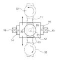
昇降台12に装備された前記フォーク装置11は、図3に示すように、基台11a、セカンダリフォーク11b、プライマリフォーク11cからなる三段式のフォーク装置である。フォーク装置11は、出退作動機構とこれを駆動する図外のフォーク用モータ29とを備え、プライマリフォーク11cを昇降台12側に引退させた図3(イ)に示す引退位置G2と、収納部4内に突入させるための図3(ロ)に示す突出位置G1とに亘って出退移動操作可能に構成された移載装置である。また、フォーク装置11は、図6に示すように、走行通路2を中心として対称的に突出作動が行えるように構成されており、収納棚1A及び1Bのいずれに対しても入出庫処理が行えるようになっている。
As shown in FIG. 3, the
なお、図3には示されていなが、フォーク装置11には、フォーク装置11が突出作動して突出位置G1に位置するとオン操作される突出側リミットスイッチSW1が設けられており、この突出側リミットスイッチSW1がオフからオンへ変化することで、後述するクレーン制御装置27は、フォーク装置11が突出位置G1に位置したことを検出できるようになっている。同様に、フォーク装置11が引退作動して引退位置G2に位置するとオン操作される引退側リミットスイッチSW2が設けられており、この引退側リミットスイッチSW2がオフからオンへ変化することで、クレーン制御装置27は、フォーク装置11が引退位置G2に位置したことを検出できるようになっている。
Although not shown in FIG. 3, the
また、フォーク装置11には、突出量検出手段としての出退用ロータリエンコーダ28が設けられており、この出退用ロータリエンコーダ28の入力軸がフォーク装置11の出退動作に伴い正逆転方向に回転操作されるようになっている。そして、出退用ロータリエンコーダ28が回転操作量に応じたパルス数を出力することにより、クレーン制御装置27はフォーク装置11の突出量を把握することができるようになっている。
Further, the
フォーク装置11のプライマリフォーク11cの上面の先端側には、物品9を載置保持するターンテーブル32が上下方向の回転軸心P1周りで回転する回転駆動軸33により軸支された状態で、プライマリフォーク11cと一体移動するように設けられている。
また、プライマリフォーク11cには、回転駆動軸33を回転駆動する回転用モータ30が内臓されており、図示しない伝動機構を通じて、回転用モータ30の回転力が回転駆動軸33に伝達され、これによりターンテーブル32が回転駆動軸33回りに回転作動するようになっている。
At the front end side of the upper surface of the
Further, the
つまり、本物品収納設備は、昇降台12に装備されて、平面視形状が矩形状の物品9を対向する一対の辺の長手方向を収納部4の奥行き方向に沿わせた状態で保持するターンテーブル32が昇降台12側に引退させた引退位置G2と収納部4内に突入させるための突出位置G1とに亘って出退移動操作されるフォーク装置11が設けられている。
また、本物品収納設備は、昇降台12に装備されたフォーク装置11のプライマリフォーク11cに設けられたターンテーブル32が、保持している平面視矩形状の物品9を上下軸心P1周りに回転操作できるように構成されている。
That is, this article storage equipment is equipped with the
Further, in this article storage facility, the
回転駆動軸33には、ターンテーブル32の回転位相を検出する回転位相検出手段としてのロータリエンコーダ31の入力軸が連動連結されており、回転駆動軸33が回転作動すると、ロータリエンコーダ31からその回転量に応じたパルス信号が出力される。これにより、後述するクレーン制御装置27がターンテーブル32の回転位相を検出することができるようになっている。なお、ターンテーブル32の回転位相は走行台車10が走行を開始したときのターンテーブル32の回転位相を基準位相(0度)としている。
An input shaft of a
前記昇降台12は、図2に示すように、走行台車10に立設した前後一対の昇降マスト13にて昇降自在に案内支持されるものであり、その左右両側に連結した昇降用チェーン14にて吊下げ支持されるようになっている。
この昇降用チェーン14は、ガイドレール6に沿って案内される上部フレーム15に設けた案内スプロケット16と一方の昇降マスト13に設けた案内スプロケット17とに巻き掛けられて、走行台車10の一端に装備した巻き取りドラム18に連結されている。
そして、巻き取りドラム18をインバータ式のモータである昇降用電動モータ19にて正逆に駆動回転させて、昇降用チェーン14の繰り出し操作や巻き取り操作で昇降台12を昇降させるように構成されている。
As shown in FIG. 2, the
The elevating
The take-
前記走行台車10には、その水平方向に測距用のビーム光を投射する昇降用レーザ測距計20と、その昇降用レーザ測距計20にて投射されたビーム光の進路を鉛直上方に屈曲させて昇降台12の下面に設置された反射板21に照射するためのミラー22とが設けられている。
そして、昇降用レーザ測距計20は、昇降台12の昇降方向において、走行台車10に設けられたミラー22の配設位置を基準位置として、その基準位置と昇降台12との距離を検出することにより、昇降経路上における昇降台12の昇降位置を検出するように構成されている。
The traveling
The lifting
また、走行台車10には、走行レール5上を走行自在な前後二つの車輪23が設けられ、それら二つの車輪23うちの車体前後方向の一端側の車輪が、インバータ式のモータである走行用電動モータ24にて駆動される推進用の駆動輪23aとして構成され、車体前後方向の他端側の車輪が、遊転自在な従動輪23bとして構成されている。
そして、走行台車10は、走行用電動モータ24の作動で走行レール5に沿って走行するように構成されている。
The traveling
The traveling
また、地上側コントローラ7側の走行レール5の端部には、水平方向に測距用のビーム光を投射する走行用レーザ測距計25が設けられ、走行台車10には、走行用レーザ測距計25からのビーム光を反射する反射板26が設けられている。
そして、走行用レーザ測距計25は、走行台車10に設置されている反射板26に向けて投射して、走行レール5の端部からの走行台車10の距離を検出することにより、走行経路上における走行台車10の走行位置を検出するように構成されている。
つまり、本物品収納設備は、昇降台12の収納棚1に対する収納部4の並び方向での位置を検出する位置検出手段として走行用レーザ測距計25を備えている。
Further, a traveling
Then, the traveling
In other words, the present article storage facility includes a traveling
このスタッカークレーン3には、図4に示すように、地上側コントローラ7からの指令に基づいて、スタッカークレーン3の運転を制御する運転制御手段としてのクレーン制御装置27が設けられている。
そして、このクレーン制御装置27に対して、昇降用レーザ測距計20の検出情報および走行用レーザ測距計25の計測情報や、突出側リミットスイッチSW1及び引退側リミットスイッチSW2や、出退用ロータリエンコーダ28及び回転用ロータリエンコーダ31からの信号が入力されるように構成されている。
As shown in FIG. 4, the
And with respect to this
前記クレーン制御装置27は、走行台車10の走行を制御する走行制御部27a、昇降台12の昇降を制御する昇降制御部27b、フォーク装置11の作動を制御する移載制御部27cなどから構成されている。
つまり、本物品収納設備は、昇降台12の移動及びフォーク装置11の出退作動を制御するクレーン制御装置27が設けられている。
そして、クレーン制御装置27は、荷載置台8の物品9を複数の収納部4のいずれかに入庫する入庫指令や、複数の収納部4のいずれかに収納されている物品9を荷載置部8に出庫する出庫指令などを地上側コントローラ7から受けると、走行台車10、昇降台12及びフォーク装置11の作動を制御して、荷載置台8の物品9を指令された収納部4に入庫する入庫動作や、指令された収納部4に収納されている物品9を荷載置部8に出庫する出庫動作を行うように構成されている。
The
In other words, the present article storage facility is provided with the
Then, the
地上側コントローラ7は、入庫指令や出庫指令とともに、移載作業対象とする収納部4或いは移載作業対象とする荷載置台8に対する目標走行停止位置Ph0、掬い用目標昇降停止位置及び卸し用目標昇降停止位置Pv0についての情報をクレーン制御装置27に送信するように構成されている。
そして、クレーン制御装置27は、入庫動作において、荷載置台8の物品9を掬い取る掬い用移載処理を実行したのち、収納部4に物品9を載置する卸し用移載処理を実行し、出庫動作において、複数の収納部4のいずれかの物品9を掬い取る掬い用移載処理を実行したのち、荷載置台8に物品9を載置する卸し用移載処理を実行する。
The
Then, the
上述の掬い用移載処理は、複数の収納部4又は荷載置台8のうちで移載作業対象とする収納部4又は荷載置台8が指示されると、昇降台12を昇降用レーザ測距系20及び走行用レーザ測距計25の検出情報に基づいて、移載作業対象とする収納部4又は荷載置台8に対する掬い用目標昇降停止位置及び目標走行停止位置Ph0に昇降台12を移動させ、フォーク装置11の突出作動と昇降台12の昇降作動とにより物品9を掬い取り、フォーク装置11の引退作動により物品9が昇降台12上に位置するように物品9を移載する処理である。
When the
また、上述の卸し用移載処理は、複数の収納部4又は荷載置台8のうちで移載作業対象とする収納部4又は荷載置台8が指示されると、昇降台12を昇降用レーザ測距系20及び走行用レーザ測距計25の検出情報に基づいて、移載作業対象とする収納部4又は荷載置台8に対する卸し用目標昇降停止位置Pv0及び目標走行停止位置Ph0に昇降台12を移動させ、フォーク装置11の突出作動と昇降台12の昇降作動とにより物品9を収納部4又は荷載置台8に載せ卸し、フォーク装置11の引退作動により物品9が収納部4又は荷載置台8に載置された状態にするように物品9を移載する処理である。
In addition, when the
そして、上記両移載処理では、昇降台12が、走行台車10の走行移動により目標走行停止位置Ph0に到達する前に、突出開始位置Ph1に移動した時点で、前記フォーク装置11を引退位置G2から突出位置G1に向けて突出作動させる突出作動制御が実行される。
In the both transfer processes, the
突出作動制御では、移載制御部27cは、出退用ロータリエンコーダ28の出力に基づいてフォーク装置11の突出量を把握しながら、その突出量が走行台車10の目標走行停止位置Ph0からの距離に対応して予目設定された目標突出量となるように、フォーク用モータ29の作動を制御する。
In the protrusion operation control, the transfer control unit 27c grasps the protrusion amount of the
つまり、本物品収納設備は、クレーン制御装置27が、複数の収納部4のうちで移載作業対象とする収納部4が指示されると、位置検出手段としての昇降用レーザ測距計20及び走行用レーザ測距計25の検出情報に基づいて、移載作業対象とする収納部4に対する目標昇降停止位置(卸し用移載処理の場合は卸し用目標昇降停止位置Pv0、掬い用移載処理の場合は掬い用目標昇降停止位置)及び目標走行停止位置Ph0に昇降台12を移動させる昇降制御及び走行制御、並びに、その昇降台12が目標走行停止位置Ph0に停止する前の突出開始位置Ph1に移動すると、フォーク装置11におけるターンテーブル32を引退位置G2から突出位置G1に向けて突出作動させることを開始して突出位置G1に突出させる早め突出制御を実行するように構成されている。
That is, in the present article storage facility, when the
前記目標走行停止位置Ph0、突出開始位置Ph1、掬い用目標昇降停止位置、及び、卸し用目標昇降停止位置Pv0は、一対の荷載置台8及び複数の収納部4の夫々に対応して定められている。
そして、掬い用目標昇降停止位置は、収納部4の載置支持部1bや荷載置台8の載置部よりも設定高さだけ低い位置が定められ、卸し用目標昇降停止位置Pv0は、収納部4の載置支持部1bや荷載置台8の載置部よりも設定高さだけ高い位置が定められている。
また、突出開始位置Ph1は、前記目標走行停止位置Ph0よりも走行台車10の走行方向で設定距離だけ手前に位置する走行速度判別用位置Ph2における昇降台12の走行状態が高速走行状態であるか低速走行状態であるかに応じて、移載処理毎に適切な位置が設定される。
The target travel stop position Ph0, the protrusion start position Ph1, the scooping target lift stop position, and the wholesale target lift stop position Pv0 are determined in correspondence with the pair of loading platforms 8 and the plurality of
The scooping target lifting / lowering stop position is set to a position that is lower than the mounting
In addition, the protrusion start position Ph1 is the traveling state of the
昇降台12の走行状態としては、具体的には、走行制御部27aが走行用レーザ測距計25の検出情報に基づいて算出する走行台車10の走行速度Vが用いられる。なお、走行台車10の走行速度Vは、昇降台12の走行速度でもある。そして、走行速度判別用位置Ph2における走行台車10の走行速度Vの値が大きいときは小さいときよりも、突出開始位置Ph1が目標走行停止位置Ph0から離れるように設定される。
Specifically, as the traveling state of the
つまり、クレーン制御装置27が、移動速度検出手段としての走行制御部27a及び走行用レーザ測距計25が検出する速度情報に基づいて移動基台の目標停止位置に対する手前箇所での走行状態を判別するように構成され、昇降台12の目標走行停止位置Ph0に対する手前箇所としての走行速度判別用位置Ph2での走行状態が高速走行状態のときには低速走行状態のときよりも、突出開始位置Ph1を目標走行停止位置Ph0から離れるように変更調整するように構成されている。
That is, the
卸し用移載処理のうち収納部4に物品9を載せ卸す場合に行われる移載処理と、掬い用移載処理のうち収納部4から物品を掬い取る場合に行われる移載処理とにおいては、クレーン制御装置27により、フォーク装置11が出退作動される間に、プライマリフォーク11cに設けたターンテーブル32は、物品が載置された状態で回転作動されるようになっている。
In the transfer process for wholesale, the transfer process performed when the
つまり、本物品収納設備は、クレーン制御装置27が早め突出制御を実行するときに、移載制御部27cが、ターンテーブル32を引退位置G2から突出位置G1に突出作動させる途中において、保持している平面視矩形状の物品9を対向する一対の辺の長手方向が収納部4の奥行き方向と交差する傾斜姿勢に姿勢変更させるべく、ターンテーブル32の回転作動を制御するように構成されている。
That is, the present article storage facility holds the transfer control unit 27c in the middle of operating the
移載制御部27cは、回転用ロータリエンコーダ31の出力に基づいてターンテーブル32の回転位相を把握しながら、その回転位相が走行台車10の目標走行停止位置Ph0からの距離に対応付けて予目設定される目標回転位相となるように、回転用モータ30の作動を制御する。
The transfer control unit 27c grasps the rotational phase of the
ターンテーブル32の回転方向は、卸し用移載処理と掬い用移載処理とで回転方向が互いに逆方向となっている。つまり、収納部4に物品9を載せ卸す際にフォーク装置11が突出される場合におけるターンテーブル32の回転方向は、卸し用移載処理が開始された時の物品9の走行台車10の走行方向側の側面が、移載作業対象とする収納部4に正対するような方向となっており、逆に、収納部4から物品9を掬い取る際にフォーク装置11が引退される場合におけるターンテーブル32の回転方向は、掬い取る際に収納部4の奥行き方向で手前側に位置する物品9の側面が、掬い取った後の走行台車10の走行方向側に向くような方向となっている。
The rotation directions of the
例えば、物品9を入庫すべく、左右の荷載置台8の何れかに載置されて入庫待ちであった物品9を掬った後、二つの収納棚1のうち地上側コントローラ7から見て左側の収納棚1の収納部4に物品を収納する場合には、卸し用移載処理により、フォーク装置11の突出作動時に平面視で反時計回りに90度だけターンテーブル32が回転作動される。
For example, in order to store the
一方、地上側コントローラ7から見て左側の収納棚1Aの収納部4に収納された物品9を出庫すべく、この物品9を収納部4から掬い取る場合には、掬い用移載処理により、フォーク装置11の突出作動時に平面視で時計回りに90度だけターンテーブル32が回転作動される。
On the other hand, when the
つまり、本物品収納設備は、クレーン制御装置27が、早め突出制御を実行するときに、ターンテーブル32を引退位置G2から突出位置G1に突出作動させる間において物品9を90度回転させるように構成されている。また、クレーン制御装置27が、収納部4に収納されている物品9を保持させたターンテーブル32を突出位置G1から引退位置G2に引退作動させる間において、保持している物品9を早め突出制御のときとは逆方向に90度回転させるように構成されている。
That is, the article storage facility is configured to rotate the
移載作業対象となる収納部4が、上述した場合と逆側の収納棚1Bに位置する場合は、図7に示すように、夫々の移載処理(卸し用移載処理及び掬い用移載処理)で回転作動されるターンテーブル32の回転方向が逆となる。このように、入庫処理における卸し用移載処理及び出庫処理における掬い用移載処理でのターンテーブル32の回転方向は、収納部4が属する収納棚1A,1Bに応じて異なる回転方向を示すことになる。
When the
つまり、物品保持部としてのターンテーブル32は、平面視矩形状の物品9の移動方向下手側でかつ移載作業対象とする収納部4が位置する側の角部が、当該収納部4の側面のうち物品9の移動方向下手側の側面の収納部入口側端部から遠ざかる向きに回転するように構成されている。
In other words, the
上記のフォーク装置11の突出作動及び引退作動並びにこれらの出退作動時に行われる回転作動は、移載制御部27cにより制御される。以下に移載制御部27cの制御動作について、地上側コントローラ7から見て左側の収納棚1Aの収納部4に物品9を収納する場合における卸し用移載処理を例に説明する。
The protrusion operation and the retraction operation of the
なお、移載作業対象として荷載置台8について卸し用移載処理が行われるときも同様である。また、掬い用移載処理は、昇降台12の目標昇降停止位置が、卸し用目標昇降停止位置Pv0に代えて掬い用目標昇降停止位置となる点と、フォーク装置11を突出作動させた後の昇降台12の昇降方向が逆になる点以外は卸し用移載処理と同様である。
The same applies when the wholesale transfer process is performed on the loading table 8 as a transfer work target. In addition, the scooping transfer process is performed after the target lift stop position of the
収納部4に物品9を収納する場合、クレーン制御装置27は、目的の収納部4に対応する目標走行停止位置Ph0及び卸し用目標昇降停止位置Pv0に昇降台12を移動させるべく、スタッカークレーン3の作動を制御するとともに、収納部4へ物品9を載置すべく、スタッカークレーン3の作動を制御する。
When the
説明を加えると、まず、走行制御部27aが、走行用レーザ測距計25の検出情報に基づいて、目標走行停止位置Ph0に走行台車10を走行させるべく、走行用電動モータ24の作動を制御する走行制御を行い、かつ、昇降制御部27bが、昇降用レーザ測距計20の検出情報に基づいて、卸し用目標昇降停止位置Pv0に昇降台12を昇降させるべく、昇降用電動モータ19の作動を制御する昇降制御を行う。
In other words, first, the traveling
走行制御部27aは、走行用レーザ測距計25の検出情報により走行台車10が走行速度判別用位置Ph2に位置したことを検出すると、移載制御部27cに対して検出信号S1及び走行台車10の走行速度Vの情報を出力する。これにより、移載制御部27cは、フォーク装置11の突出作動を開始させる位置である突出開始位置Ph1を決定するための突出開始位置設定処理を実行する。
When the traveling
そして、移載制御部27cは、走行用レーザ測距計25の検出情報に基づき、走行台車10が設定された突出開始位置Ph1まで移動したことを検出すると、走行台車12の走行移動が完了する前にフォーク装置11の突出作動を開始すべく、フォーク用モータ29の作動を制御して、引退位置G2にあるフォーク装置11におけるターンテーブル32を突出位置G1に変更するべくフォーク装置11の突出作動を開始させる。
When the transfer control unit 27c detects that the traveling
そして、移載制御部27cは、走行用レーザ測距計25の検出情報に基づき、走行台車10が設定された回転開始位置Ph3まで移動したことを検出すると、回転用モータ30の駆動を開始させ、ターンテーブル33を回転作動させる。このようにして、移載制御部27cは、早め突出制御を実行するときに、フォーク装置11を引退位置G2から突出位置G1に突出作動させる途中において、ターンテーブル33を回転作動させる。
When the transfer control unit 27c detects that the traveling
目標走行停止位置Ph0の移動手前位置においては、走行台車10の走行速度が減速されながらフォーク装置11が突出作動され、フォーク装置11の突出作動途中で、ターンテーブル32が回転作動されることになる。より具体的には、走行用レーザ測距計25、出退用ロータリエンコーダ28及び回転用ロータリエンコーダ31の各出力情報に基づいて、突出作動されるフォーク装置11の突出量及び回転作動されるターンテーブル32の回転位相が、走行作動する走行台車10の目標走行停止位置Ph0までの距離に対応して設定された目標突出量及び目標回転位相となるように、フォーク装置11の突出作動及びターンテーブル32の回転作動が制御される。
At the position before the movement of the target travel stop position Ph0, the
走行台車10が目標走行停止位置Ph0に停止するまでに各走行位置に位置する時刻とフォーク装置11の突出作動及びターンテーブル32の回転作動との関係を示すと図8のようになる。図8において曲線で示された部分、即ち、ターンテーブル32の引退位置G2から突出位置G1への変化状態、及び、ターンテーブル32の回転位相が0度から90まで変化する変化状態は、突出開始位置Ph1を通過した後の走行台車10の走行位置の変化状態に応じたものとなっている。
FIG. 8 shows the relationship between the time at which the traveling
図8に示す時刻t1、t3、t4及びt5における昇降台12、フォーク装置11及び回転テーブル32の平面視での位置を時間経過に沿って表わすと図9(イ)及び(ロ)図並びに10(ハ)及び(ニ)に示すようになる。
When the positions of the
図9(イ)の実線で示すターンテーブル32の位置は、昇降台12が昇降速度判別用位置Ph2に位置したとき、つまり、図8で示す時刻t2における位置であり、図9(イ)の二点鎖線で示すターンテーブル32の位置は、昇降台12が突出開始位置Ph1に位置したとき、つまり、図8で示す時刻t1における位置である。時刻t2〜t1の間では、フォーク装置11は引退位置G2で維持されているので、回転テーブル32の平面視での位置は、走行台車10の走行作動により収納部4の横並び方向に沿って移動する。
The position of the
図9(ロ)の実線で示すターンテーブル32の位置は、昇降台12が突出開始位置Ph1に位置したとき、つまり、図8で示す時刻t1における位置であり、図9(ロ)の二点鎖線で示すターンテーブル32の位置は、昇降台12が回転開始位置Ph3に位置したとき、つまり、図8で示す時刻t3における位置である。時刻t1〜t3の間では、回転テーブル32の平面視での位置は、減速しつつ走行する走行台車10の走行作動とフォーク装置11の突出作動とにより移動する。
The position of the
図10(ハ)の実線で示すターンテーブル32の位置は、昇降台12が回転開始位置Ph3に位置したとき、つまり、図8で示す時刻t3における位置であり、図10(ハ)の二点鎖線で示すターンテーブル32の位置は、回転テーブル32が90度回転したとき、つまり、図8で示す時刻t4における位置(以下、回転終了位置P4という。)である。時刻t3〜t4の間では、回転テーブル32の平面視での位置は、時刻t1〜t3の間と同様に、減速しつつ走行する走行台車10の走行作動とフォーク装置11の突出作動とにより移動する。
The position of the
時刻t3〜t4の間では、回転テーブル32の回転作動が行われるので、ターンテーブル32上の物品9の姿勢は図13に示すように、平面視矩形状の物品9の対向する一対の辺の長手方向が収納部4の奥行き方向と交差する傾斜姿勢を経て半時計回りに90度変化する。なお、図13に示すRは、昇降台12が突出開始位置Ph1に位置したときにフォーク装置11の突出作動が開始され、その後、物品9が傾斜姿勢をとらずに突出作動及び走行作動が進行した場合の、移動方向下手側端部でかつ移載作業対象とする収納部4が位置する収納部1A側である角部の移動軌跡を示している。図13の移動軌跡Rの位置からわかるように、物品9が傾斜姿勢をとることなく上記の突出開始位置Ph1にて突出作動が行われる場合には、収納棚1Aと物品9とが干渉してしまうことが分かる。
Since the rotation operation of the
図10(ニ)の一点鎖線で示すターンテーブル32の位置は、昇降台12が回転終了位置Ph4に位置したとき、つまり、図8で示す時刻t4における位置であり、図10(ニ)の実線で示すターンテーブル32の位置は、昇降台12が目標走行停止位置Ph0に位置したとき、つまり、図8で示す時刻t0における位置であり、図10(ニ)の二点鎖線で示すターンテーブル32の位置は、昇降台12が目標走行停止位置Ph0に位置した状態でフォーク装置11の突出作動が完了したとき、つまり、図8で示す時刻t5における位置である。
The position of the
時刻t4〜t0の間では、回転テーブル32の平面視での位置は、時刻t1〜t3及びt3〜t4の間と同様に、減速しつつ走行する走行台車10の走行作動とフォーク装置11の突出作動とにより移動する。そして、時刻t0〜t5の間では、回転テーブル32の平面視での位置は、フォーク装置11の突出作動により収納棚4の奥行き方向に沿って突出位置G1まで移動する
During the time t4 to t0, the position of the rotary table 32 in plan view is the same as during the times t1 to t3 and t3 to t4. The traveling operation of the traveling
以上に説明したように、移載制御部27cは、保持部としてのターンテーブル32の回転作動を制御して、保持部を引退位置G2から突出位置g1に突出作動させる途中において、保持している平面視矩形状の物品9を対向する一対の辺の長手方向が収納部4の奥行き方向と交差する傾斜姿勢に姿勢変更させるように構成されている。
As described above, the transfer control unit 27c controls the rotation operation of the
図8、図9及び図10に示すように、走行台車10が時刻t0で目標走行停止位置Ph0に停止する前にターンテーブル32の回転作動は時刻t4で完了する。そして、時刻t0に走行台車10が目標走行停止位置Ph0に停止するときには、ターンテーブル上に載置された物品9の姿勢は、時刻t3での姿勢から反時計回りに90度回転した姿勢に変化しており、この姿勢を維持したまま、フォーク装置11の突出作動が継続し、時刻t5でターンテーブル32が突出位置G1に位置すると、フォーク装置11の突出作動を停止するべくフォーク用モータ29の作動を制御する。
As shown in FIGS. 8, 9, and 10, the rotation operation of the
フォーク装置11の突出位置G1への突出作動が完了すると、昇降制御部27bが、設定高さだけ昇降台12を下降させるべく、昇降用電動モータ19の作動を制御する。このようにして、フォーク装置11を突出させた状態で昇降台12を下降させることにより、収納部4の載置支持部1bに物品9が載置された状態となり、最後に、移載制御部27cが、フォーク装置11を引退位置G2まで、引退させるべく、フォーク用モータ29の作動を制御する。
When the protrusion operation of the
こうして収納棚1Bにある収納部4へ物品9を載置する卸し用移載処理が完了すると、昇降台12は、走行制御部27aが行う走行制御及び昇降制御部27bが行う昇降制御により、次の目的とする掬い位置に対する目標走行停止位置及び掬い用目標昇降停止位置に移動する。
When the wholesale transfer process for placing the
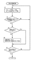
以下、上述した卸し用移載処理における移載制御部27cの制御動作について図11のフローチャートに基づいて説明する。
移載制御部27cは、走行台車10が走行速度判別用位置Ph2に移動して、走行制御部27aが検出信号S1を出力するまで待機状態となっている(ステップ#1)。移載制御部27cは、走行制御部27aが出力する検出信号S1を受信すると、突出開始位置設定処理を実行する(ステップ#2)。これにより、当該移載処理における目標走行停止位置Ph0に対する手前箇所での走行状態に応じた突出開始位置が設定される。
Hereinafter, the control operation of the transfer control unit 27c in the above-described wholesale transfer process will be described with reference to the flowchart of FIG.
The transfer control unit 27c is in a standby state until the traveling
そして、設定された突出開始位置Ph1に走行台車10が移動したことが判別されると、昇降台12の昇降位置の確認が行われる(ステップ#3〜ステップ#4)。なお、昇降用レーザ測距計20及び走行用レーザ測距計25の計測情報は走行制御部27a及び昇降制御部27bのみならず、移載制御部27cにも入力されている(図4参照)ので、走行台車10と昇降台12の位置情報は、走行制御部27aや昇降制御部27bを介さずに移載制御部27cにより直接取得される。
When it is determined that the traveling
ステップ#4の処理は、昇降台12が卸し用目標昇降停止位置Pv0まで昇降移動している途中にフォーク装置11の突出作動が開始された場合に、収納棚4の載置指示部1b等とフォーク装置11或いは載置された物品9とが接触しないように、走行台車10が突出開始位置Ph1に移動した時点での昇降台12の昇降位置を確認する処理である。
The process of
具体的には以下のような処理を行う。即ち、移載制御部27cは、走行台車10が突出開始位置Ph1に移動した時点での昇降台12の昇降位置を、昇降用レーザ測距計20の計測情報に基づいて取得し、その時の昇降台12の昇降位置が、当該移載処理についての卸し用目標昇降停止位置Pv0から昇降方向で手前側に設定距離だけ離れた突出許可昇降位置Pv1を超えているかどうか(突出許可昇降位置Pv1よりも卸し用目標昇降停止位置Pv0側かどうか)を判別する。
Specifically, the following processing is performed. That is, the transfer control unit 27c acquires the lift position of the
なお、卸し用目標昇降停止位置Pv0は物品9の下面が支持部1bよりも若干上側に位置する位置として夫々の収納部4に対して設定されている。また、突出許可昇降位置Pv1の位置は、昇降台12が卸し用目標昇降停止位置Pv0に下降移動により移動する場合は、卸し用目標昇降停止位置Pv0より高い位置となり、上昇移動により移動する場合は、卸し用目標昇降停止位置Pv0より低い位置となる。
The wholesale target lift stop position Pv0 is set with respect to each
走行台車10が突出開始位置Ph1に移動した時点での昇降台12の昇降位置が突出許可昇降位置Pv1を超えていれば、突出作動制御の実行が開始され(ステップ#5)、突出許可昇降位置Pv1を超えていなければ、昇降制御部27bによる昇降作動が進行して昇降台12の昇降位置が突出許可昇降位置Pv1を超えるまで突出作動制御の実行は開始されない。
突出作動制御の実行が終了すると、移載制御部27cは、突出完了信号S2を昇降制御部27bに対して出力する(ステップ#6)。この時点が、図8における時刻t5に相当し、物品9は、物品収納棚1の収納部4内に突入した状態となっている(図3(ロ)、図10(ニ)の二点差線で示す状態)。
If the lifting position of the
When the execution of the protrusion operation control is completed, the transfer controller 27c outputs a protrusion completion signal S2 to the
突出完了信号S2を受信した昇降制御部27bは、フォーク装置11に載置された物品9が、物品収納棚1の載置支持部1bに支持された状態となるように、昇降台12を設定量だけ下降させ、この設定量の下降作動が完了すると、昇降完了信号S3を移載制御部27cに対して出力する。この時点で、物品9は、物品収納棚1の収納部4内に収納された状態となっている。
The lifting
移載制御部27cは、昇降制御部27bからの昇降完了信号S3を受信するまでは、フォーク装置11の引退作動を開始させず待機状態となっている(ステップ#7)。移載制御部27cは、昇降完了信号S3を受信してフォーク装置11の引退作動を開始すると、先述の引退側リミットスイッチSW2がオンするまで、つまり、フォーク装置11のプライマリフォーク11cが引退位置G2に位置するまで継続して、フォーク用モータ29を引退作動用の回転方向にて駆動させる(ステップ#8,ステップ#9)。フォーク装置11が引退位置G2まで移動されると、移載制御装置27cは、引退完了信号S4を走行制御部27a及び昇降制御部27bに対して出力(ステップ#10)して卸し用移載制御を終了する。
The transfer control unit 27c is in a standby state without starting the retraction operation of the
上述した図11のステップ#2で実行される突出開始位置設定処理では、図12に示すように、移載制御部27cは、走行制御部27aが出力する走行台車10の走行速度Vの値を受信し(ステップ#1)、走行台車10の走行速度Vの値に基づいて、フォーク装置11の突出作動を開始する位置である突出開始位置Ph1を設定する(ステップ#2)。
In the protrusion start position setting process executed in
上述した図11のステップ#5で実行される突出作動制御では、図14のフローチャートに示すような処理が実行される。図14のステップ#1で、移載制御部27cは、出退用ロータリエンコーダ28の出力に基づいてフォーク装置11の突出量が走行台車10の目標走行停止位置Ph0からの距離に対応して予目設定された目標突出量となるように、フォーク用モータ29の回転作動を制御する。
In the protrusion operation control executed in
移載制御部27cは、フォーク用モータ29の回転作動の制御を開始したのち、走行用レーザ測距計25の検出情報に基づき走行台車10が回転開始位置Ph3まで移動したことを検出すると(ステップ#2)、回転用モータ30の駆動を開始させ、ターンテーブル32を反時計回りに回転作動させる(ステップ#4)回転作動制御の実行を開始する。ステップ#3でターンテーブル32の回転位相が90度に変化していれば、回転作動が完了したとして、それ以上の回転作動制御は行われない。
After starting the control of the rotation operation of the
回転作動制御では、移載制御部27cは、回転用ロータリエンコーダ31の出力に基づいてターンテーブル32の回転位相を把握しながら、その回転位相が走行台車10の目標走行停止位置Ph0からの距離に対応付けて予目設定される目標回転位相となるように、回転用モータ30の作動を制御する。
In the rotation operation control, the transfer control unit 27c grasps the rotation phase of the
移載制御部27cは、フォーク装置11の突出作動を開始すると、出退用ロータリエンコーダ28の検出情報に基づいて、ターンテーブル32が突出位置G1に位置したことを検出するまで、回転用モータの作動を開始してから停止するまでの間も含めて、フォーク用モータ29を突出作動用の回転方向にて駆動させる(ステップ#5)。
When the transfer control unit 27c starts the protrusion operation of the
なお、出退用ロータリエンコーダ28の検出情報に基づいて突出位置G1に位置したことを検出するまでに、先述の突出側リミットスイッチSW1がオンした場合も、ステップ#5でターンテーブル32が突出位置G1まで突出したと判別され、突出作動制御を終了するようになっている。
Even if the above-mentioned protrusion-side limit switch SW1 is turned on until it is detected that the protrusion is positioned at the protrusion position G1 based on the detection information of the
以上のように、本物品収納設備では、フォーク装置11を突出作動させる途中において、ターンテーブル32に載置保持している平面視矩形状の物品9を対向する一対の辺の長手方向が前記収納部の奥行き方向と交差する傾斜姿勢に姿勢変更させるべく、保持部としてのターンテーブル32の回転作動を制御するので、突出開始位置Ph0を目標走行停止位置Ph0から一層離れた位置に設定することができる。したがって、目標走行停止位置Ph0に到着するまでにフォーク装置11の突出作動をより多く作動させることができるので、入庫動作に要する時間を短縮することができる。
As described above, in the present article storage facility, the longitudinal direction of the pair of sides facing the
また、本物品収納設備では、フォーク装置11を引退作動させる途中において、ターンテーブル32に載置保持している平面視矩形状の物品9を対向する一対の辺の長手方向が前記収納部の奥行き方向と交差する傾斜姿勢に姿勢変更させるべく、突出作動させる途中において回転作動させた回転方向とは逆向きに同量(90度)だけ回転作動させるので、収納部4に収納された物品を掬い取って、荷載置台8へ移送する出庫処理を行うにあたって、収納部4に対応する移載作業位置でフォーク装置11の引退作動が完了する前に荷載置台8へ向う移動操作のうち、昇降台12の収納棚並び方向に沿った移動操作を早期に開始することが可能となる。これにより、入庫動作に要する時間を短縮することができる。
In the present article storage facility, the longitudinal direction of the pair of sides facing the
そして、フォーク装置11の突出開始位置Ph1を走行速度判別用位置Ph2における走行台車10の走行速度Vに応じて変更調整することにより、昇降台12の目標走行停止位置Ph0に対する手前箇所の走行速度Vが速くても、フォーク装置11の突出作動が開始されてから走行台車10が目標走行停止位置Ph0に停止するまでに要する時間を長くすることができ、入庫動作に要する時間を一層短縮することができる。
Then, by changing and adjusting the protrusion start position Ph1 of the
〔別実施形態〕
以下、別実施形態を列記する。
[Another embodiment]
Hereinafter, other embodiments are listed.
(1)上記実施形態では、移載制御部27cが、回転用ロータリエンコーダ31の出力に基づいてターンテーブル32の回転位相を把握しながら、その回転位相が走行台車10の目標走行停止位置Ph0からの距離に対応付けて予目設定される目標回転位相となるように回転用モータの作動を制御するように構成されたものを例示したが、これに限らず、移載制御部27cが、回転用モータの回転速度を積極的に制御せず、ターンテーブル32を一定の回転作動速度で作動させるように構成されたものであってもよい。この場合図8に示す回転作動が開始された後のターンテーブル32の回転位相と時間との関係は略線形関係となる。
(1) In the above embodiment, the transfer control unit 27 c grasps the rotational phase of the
(2)上記実施形態では、移載制御部27cが、出退用ロータリエンコーダ28の出力に基づいてターンテーブル32の出退位置を把握しながら、その出退位置が走行台車10の目標走行停止位置Ph0からの距離に対応付けて予目設定される目標出退位置となるようにフォーク用モータの作動を制御するように構成されたものを例示したが、これに限らず、フォーク用モータの回転速度を積極的に制御せず、フォーク装置11を一定の突出作動速度で作動させるように構成されたものであってもよい。この場合図8に示す突出作動が開始された後のターンテーブル32の位置と時間との関係は略線形関係となる。
(2) In the above embodiment, the transfer control unit 27 c grasps the exit / retreat position of the
(3)上記実施形態では、移載制御部27cは、フォーク装置11の突出作動を開始してから所定の時間(図8で説明すると「t3−t1」)が経過してからターンテーブル32の回転作動を開始するように構成されたものを例示したが、これに限らず、フォーク装置11の突出作動を開始するのと同時にターンテーブル32の回転作動を開始してもよい。
(3) In the above-described embodiment, the transfer control unit 27c is configured to move the
(4)上記実施形態では、移載制御部27cは、走行台車10が回転開始位置Ph3に移動したときにターンテーブル32の回転作動を開始するように構成されたものを例示したが、移載制御部27cが、出退用ロータリエンコーダ28の検出情報に基づいてターンテーブル32の回転作動を開始するように構成してもよい。
(4) In the above embodiment, the transfer control unit 27c is exemplified to be configured to start the rotation operation of the
(5)上記実施形態では、回転開始位置Ph3は、目標走行停止位置Ph0に対応した所定の位置に設定されたものを例示したが、回転開始位置Ph3を突出開始位置Ph2と同様に、速度判別用位置Ph2の走行状態が高速走行状態のときには低速走行状態のときよりも、目標走行停止位置Ph0から離れるように変更調整するように構成してもよい。 (5) In the above embodiment, the rotation start position Ph3 is set to a predetermined position corresponding to the target travel stop position Ph0. However, the rotation start position Ph3 is speed-determined in the same manner as the protrusion start position Ph2. When the traveling state of the working position Ph2 is in the high speed traveling state, the adjustment may be made so as to be away from the target traveling stop position Ph0 as compared with the low speed traveling state.
(6)上記実施形態では、目標走行停止位置Ph0に対する手前箇所での走行状態を、速度判別用位置Ph1における走行台車10の走行速度Vにより判別しているが、これに代えて、地上側コントローラ7が、クレーン制御装置27に対して移載処理の制御指令を指令するときに、移載処理の条件(例えば、移載される物品9の重量や荷姿等)に応じて、異なる昇降作動及び走行作動を行うように指令するように構成され、地上側コントローラ7により、クレーン制御装置27が、走行台車10を目標走行停止位置Ph0の手前箇所において大きな減速度で減速させながら目標走行停止位置Ph0に停止させる急減速状態となるように指令されるか、小さな減速度で減速させながら目標走行停止位置Ph0に停止させる緩減速状態となるように指令されるかにより、目標走行停止位置Ph0に対する手前箇所での走行状態を判別してもよい。
(6) In the above-described embodiment, the running state at the front position with respect to the target running stop position Ph0 is discriminated by the running speed V of the running
この場合、クレーン制御装置27が、地上側コントローラ7により目標走行停止位置Ph0の手前箇所において大きな減速度で減速させながら目標走行停止位置Ph0に停止するように指令された場合には、小さな減速度で減速させながら目標走行停止位置Ph0に停止するように指令された場合よりも、突出開始位置Ph1を目標走行停止位置Ph0から離れた位置を設定することになる。
In this case, when the
(7)上記実施形態では、走行台車10が突出開始位置Ph1まで移動したときの昇降台12の昇降位置が、突出許可昇降位置Pv1より卸し(或いは掬い)用目標昇降停止位置Pv0側かどうかを判別しているが、この突出許可昇降位置Pv1が、卸し(或いは掬い)用の目標昇降停止位置Pv0の手前側に設けられた昇降速度判別用位置Pv2での昇降台12の昇降速度Vvの大小に応じて異なる位置に変更調節されるように構成してもよい。
この場合、昇降速度判別用位置Pv2での昇降台12の昇降速度Vvが大きいときは小さいときよりも、突出許可昇降位置Pv1は目標昇降停止位置Pv0から離れるように設定されることになる。
(7) In the above embodiment, whether the lifting position of the
In this case, when the lifting speed Vv of the
(8)上記実施形態では、走行台車10の走行状態が高速走行状態であるか低速走行状態であるかにより、目標走行停止位置Ph0までの距離を変化させて走行方向手前側における突出開始位置Ph1を変更調節するように構成された物品収納設備を例示したが、これに代えて、昇降台12の昇降状態が高速走行状態であるか低速走行状態であるかにより、卸し(或いは掬い)用目標昇降停止位置Pv0までの距離を変化させて昇降方向手前側における突出開始位置Pv1を変更調節するように構成されたものであってもよい。
(8) In the above embodiment, the protrusion start position Ph1 on the front side in the traveling direction is changed by changing the distance to the target traveling stop position Ph0 depending on whether the traveling state of the traveling
(9)前項(8)の構成とする場合は、卸し(或いは掬い)用目標昇降停止位置Pv0に対して設定距離を離れた昇降速度判別用位置Pv1における昇降台12の昇降速度Vvを検出する移動速度検出手段が、昇降用レーザ測距計20と昇降制御部27bとで構成されることになる。そして、移載制御部27cが、昇降制御部27bから昇降台12の昇降速度Vvを取得して、昇降台12の卸し(或いは掬い)用の目標昇降停止位置Pv0に対する手前箇所での走行状態を判別するように構成されることになる。
(9) In the case of the configuration of (8), the lifting speed Vv of the
(10)前項(9)の構成に代えて、昇降台12の卸し(或いは掬い)用目標昇降停止位置Pv0に対する手前箇所での走行状態を、昇降制御部27bが、地上側コントローラ7により目標昇降停止位置Pv0の手前箇所において大きな減速度で減速させながら目標昇降停止位置Pv0に停止させる急減速状態となるような昇降作動指令が指令されるか、目標昇降停止位置Pv0の手前箇所において小さな減速度で減速させながら目標昇降停止位置Pv0に停止させる緩減速状態となるような昇降作動指令が指令されるか、に基づいて、昇降台12の目標昇降停止位置Pv0に対する手前箇所での走行状態を判別するように構成してもよい。
(10) Instead of the configuration of the previous item (9), the
(11)上記実施形態では、移動基台がスタッカークレーン3に備えられた昇降台12にて構成されたものを例示したが、これに限らず、収納部が並設された収納棚の前面側において収納部の並び方向に移動操作されるものであればよい。
(11) In the above embodiment, the moving base is configured by the
(12)上記実施形態では、収納棚として、収納部が縦横に複数並べて設けられたものを例示したが、これに限らず、収納部が横方向にだけ並べて設けられたものでもよい。 (12) In the above embodiment, as the storage shelf, a plurality of storage units are arranged in the vertical and horizontal directions. However, the present invention is not limited to this, and the storage unit may be provided only in the horizontal direction.
G1 突出位置
G2 引退位置
P1 回転軸心
Ph0 目標停止位置
Ph1 突出開始位置
Ph2 目標停止位置に対する手前箇所
1,1A,1B 収納棚
4 収納部
9 物品
11 移載装置
12 移動基台
25 位置検出手段
27 運転制御手段
32 物品保持部
G1 Projection position G2 Retraction position P1 Rotational axis Ph0 Target stop position Ph1 Projection start position
Claims (3)
その収納棚の前面側において前記収納部の並び方向に移動操作される移動基台と、
その移動基台に装備されて、平面視形状が矩形状の物品を対向する一対の辺の長手方向を前記収納部の奥行き方向に沿わせた状態で保持する物品保持部が前記移動基台側に引退させた引退位置と前記収納部内に突入させるための突出位置とに亘って出退移動操作される移載装置と、
前記移動基台の前記収納棚に対する前記収納部の並び方向での位置を検出する位置検出手段と、
前記移動基台の移動及び前記移載装置における前記保持部の出退作動を制御する運転制御手段とが設けられ、
前記運転制御手段が、前記複数の収納部のうちで移載作業対象とする収納部が指示されると、前記位置検出手段の検出情報に基づいて、移載作業対象とする収納部に対する目標停止位置に前記移動基台を移動させる移動制御、及び、その移動基台が目標停止位置に停止する前の突出開始位置に移動すると、前記移載装置における保持部を引退位置から突出位置に向けて突出作動させることを開始して突出位置に突出させる早め突出制御を実行するように構成されている物品収納設備であって、
前記物品保持部が、保持している平面視矩形状の物品を上下軸心周りに回転操作できるように構成され、
前記運転制御手段が、前記早め突出制御を実行するときに、前記保持部を前記引退位置から前記突出位置に突出作動させる途中において、保持している平面視矩形状の物品を対向する一対の辺の長手方向が前記収納部の奥行き方向と交差する傾斜姿勢に姿勢変更させる形態で、前記保持部を前記引退位置から前記突出位置に突出作動させる間において物品を90度回転させるように制御するように構成されている物品収納設備。 A storage shelf in which a plurality of storage units that store a pair of sides facing the article having a rectangular shape in plan view along the depth direction are arranged in parallel in the width direction;
A movable base that is operated to move in the direction in which the storage units are arranged on the front side of the storage shelf;
An article holding part that is mounted on the moving base and holds the article having a rectangular shape in plan view in a state where the longitudinal direction of a pair of sides facing each other is along the depth direction of the storage part is on the moving base side A transfer device that is operated to move out and retract across a retired position that has been retired and a projecting position for rushing into the storage unit;
Position detecting means for detecting the position of the storage unit in the direction in which the storage units are arranged with respect to the storage shelf;
An operation control means for controlling the movement of the moving base and the moving operation of the holding unit in the transfer device; and
When the operation control means is directed to a storage section to be transferred among the plurality of storage sections, the target stop for the storage section to be transferred is based on the detection information of the position detection means. When the movement base moves to the position, and the movement base moves to the protruding start position before stopping at the target stop position, the holding unit in the transfer device is moved from the retracted position toward the protruding position. An article storage facility configured to execute early protrusion control to start protrusion operation and protrude to a protrusion position,
The article holding unit is configured to be able to rotate a rectangular article in plan view that is held around a vertical axis,
When the operation control means performs the early protrusion control, a pair of sides facing a rectangular object in plan view that is held while the holding portion is being operated to protrude from the retracted position to the protruding position. In such a manner that the posture is changed to an inclined posture in which the longitudinal direction of the storage unit intersects the depth direction of the storage unit, the article is controlled to rotate 90 degrees while the holding unit is protruded from the retracted position to the protruding position. Goods storage equipment configured in
Priority Applications (1)
| Application Number | Priority Date | Filing Date | Title |
|---|---|---|---|
| JP2005169517A JP4399738B2 (en) | 2005-06-09 | 2005-06-09 | Goods storage equipment |
Applications Claiming Priority (1)
| Application Number | Priority Date | Filing Date | Title |
|---|---|---|---|
| JP2005169517A JP4399738B2 (en) | 2005-06-09 | 2005-06-09 | Goods storage equipment |
Publications (2)
| Publication Number | Publication Date |
|---|---|
| JP2006341960A JP2006341960A (en) | 2006-12-21 |
| JP4399738B2 true JP4399738B2 (en) | 2010-01-20 |
Family
ID=37639209
Family Applications (1)
| Application Number | Title | Priority Date | Filing Date |
|---|---|---|---|
| JP2005169517A Expired - Fee Related JP4399738B2 (en) | 2005-06-09 | 2005-06-09 | Goods storage equipment |
Country Status (1)
| Country | Link |
|---|---|
| JP (1) | JP4399738B2 (en) |
Families Citing this family (1)
| Publication number | Priority date | Publication date | Assignee | Title |
|---|---|---|---|---|
| JP5310686B2 (en) * | 2010-09-28 | 2013-10-09 | 村田機械株式会社 | Article conveying device |
-
2005
- 2005-06-09 JP JP2005169517A patent/JP4399738B2/en not_active Expired - Fee Related
Also Published As
| Publication number | Publication date |
|---|---|
| JP2006341960A (en) | 2006-12-21 |
Similar Documents
| Publication | Publication Date | Title |
|---|---|---|
| JP4586990B2 (en) | Goods storage equipment | |
| EP1741644B1 (en) | Article storage facility | |
| EP2112095B1 (en) | Article conveyance device | |
| JP4140015B2 (en) | Moving body traveling device | |
| JP6597551B2 (en) | Goods transport equipment | |
| US20080044262A1 (en) | Article storage facility and operation method thereof | |
| EP1728738A1 (en) | Article transport facility and a method of operating the facility | |
| JP2007070106A (en) | Article transport device in article storage facility | |
| JP2007119136A (en) | Article transfer equipment and article conveyance equipment provided with the article transfer equipment | |
| JP4947359B2 (en) | Article conveying device | |
| JP4618505B2 (en) | Article conveying device | |
| JP5765577B2 (en) | Stacker crane | |
| JP6627677B2 (en) | Goods storage equipment | |
| JP4534152B2 (en) | Goods storage equipment | |
| JP4399738B2 (en) | Goods storage equipment | |
| JP6870643B2 (en) | Goods transport device | |
| JP5168557B2 (en) | Fork-type article transfer device | |
| JP4026436B2 (en) | Goods transport equipment | |
| JP4399734B2 (en) | Lifting type article transport device | |
| JP4973927B2 (en) | Article conveying device | |
| JP4399737B2 (en) | Article transfer device | |
| JP4257590B2 (en) | Lifting type article transport device | |
| JP2001301988A (en) | Loading system | |
| JP4905774B2 (en) | Goods storage equipment | |
| JPH11199010A (en) | Article storage installation |
Legal Events
| Date | Code | Title | Description |
|---|---|---|---|
| A621 | Written request for application examination |
Free format text: JAPANESE INTERMEDIATE CODE: A621 Effective date: 20061215 |
|
| A977 | Report on retrieval |
Free format text: JAPANESE INTERMEDIATE CODE: A971007 Effective date: 20090917 |
|
| TRDD | Decision of grant or rejection written | ||
| A01 | Written decision to grant a patent or to grant a registration (utility model) |
Free format text: JAPANESE INTERMEDIATE CODE: A01 Effective date: 20091001 |
|
| A01 | Written decision to grant a patent or to grant a registration (utility model) |
Free format text: JAPANESE INTERMEDIATE CODE: A01 |
|
| A61 | First payment of annual fees (during grant procedure) |
Free format text: JAPANESE INTERMEDIATE CODE: A61 Effective date: 20091014 |
|
| R150 | Certificate of patent or registration of utility model |
Free format text: JAPANESE INTERMEDIATE CODE: R150 |
|
| FPAY | Renewal fee payment (event date is renewal date of database) |
Free format text: PAYMENT UNTIL: 20121106 Year of fee payment: 3 |
|
| FPAY | Renewal fee payment (event date is renewal date of database) |
Free format text: PAYMENT UNTIL: 20121106 Year of fee payment: 3 |
|
| FPAY | Renewal fee payment (event date is renewal date of database) |
Free format text: PAYMENT UNTIL: 20121106 Year of fee payment: 3 |
|
| FPAY | Renewal fee payment (event date is renewal date of database) |
Free format text: PAYMENT UNTIL: 20131106 Year of fee payment: 4 |
|
| R250 | Receipt of annual fees |
Free format text: JAPANESE INTERMEDIATE CODE: R250 |
|
| R250 | Receipt of annual fees |
Free format text: JAPANESE INTERMEDIATE CODE: R250 |
|
| R250 | Receipt of annual fees |
Free format text: JAPANESE INTERMEDIATE CODE: R250 |
|
| R250 | Receipt of annual fees |
Free format text: JAPANESE INTERMEDIATE CODE: R250 |
|
| R250 | Receipt of annual fees |
Free format text: JAPANESE INTERMEDIATE CODE: R250 |
|
| LAPS | Cancellation because of no payment of annual fees |