JP4390814B2 - Powertrain control device, control method, program for realizing the method, and recording medium recording the program - Google Patents
Powertrain control device, control method, program for realizing the method, and recording medium recording the program Download PDFInfo
- Publication number
- JP4390814B2 JP4390814B2 JP2007042785A JP2007042785A JP4390814B2 JP 4390814 B2 JP4390814 B2 JP 4390814B2 JP 2007042785 A JP2007042785 A JP 2007042785A JP 2007042785 A JP2007042785 A JP 2007042785A JP 4390814 B2 JP4390814 B2 JP 4390814B2
- Authority
- JP
- Japan
- Prior art keywords
- rotating element
- rotating
- engine
- torque
- rotation speed
- Prior art date
- Legal status (The legal status is an assumption and is not a legal conclusion. Google has not performed a legal analysis and makes no representation as to the accuracy of the status listed.)
- Expired - Fee Related
Links
Images


Classifications
-
- B—PERFORMING OPERATIONS; TRANSPORTING
- B60—VEHICLES IN GENERAL
- B60L—PROPULSION OF ELECTRICALLY-PROPELLED VEHICLES; SUPPLYING ELECTRIC POWER FOR AUXILIARY EQUIPMENT OF ELECTRICALLY-PROPELLED VEHICLES; ELECTRODYNAMIC BRAKE SYSTEMS FOR VEHICLES IN GENERAL; MAGNETIC SUSPENSION OR LEVITATION FOR VEHICLES; MONITORING OPERATING VARIABLES OF ELECTRICALLY-PROPELLED VEHICLES; ELECTRIC SAFETY DEVICES FOR ELECTRICALLY-PROPELLED VEHICLES
- B60L15/00—Methods, circuits, or devices for controlling the traction-motor speed of electrically-propelled vehicles
- B60L15/20—Methods, circuits, or devices for controlling the traction-motor speed of electrically-propelled vehicles for control of the vehicle or its driving motor to achieve a desired performance, e.g. speed, torque, programmed variation of speed
- B60L15/2054—Methods, circuits, or devices for controlling the traction-motor speed of electrically-propelled vehicles for control of the vehicle or its driving motor to achieve a desired performance, e.g. speed, torque, programmed variation of speed by controlling transmissions or clutches
-
- B—PERFORMING OPERATIONS; TRANSPORTING
- B60—VEHICLES IN GENERAL
- B60L—PROPULSION OF ELECTRICALLY-PROPELLED VEHICLES; SUPPLYING ELECTRIC POWER FOR AUXILIARY EQUIPMENT OF ELECTRICALLY-PROPELLED VEHICLES; ELECTRODYNAMIC BRAKE SYSTEMS FOR VEHICLES IN GENERAL; MAGNETIC SUSPENSION OR LEVITATION FOR VEHICLES; MONITORING OPERATING VARIABLES OF ELECTRICALLY-PROPELLED VEHICLES; ELECTRIC SAFETY DEVICES FOR ELECTRICALLY-PROPELLED VEHICLES
- B60L50/00—Electric propulsion with power supplied within the vehicle
- B60L50/10—Electric propulsion with power supplied within the vehicle using propulsion power supplied by engine-driven generators, e.g. generators driven by combustion engines
- B60L50/16—Electric propulsion with power supplied within the vehicle using propulsion power supplied by engine-driven generators, e.g. generators driven by combustion engines with provision for separate direct mechanical propulsion
-
- B—PERFORMING OPERATIONS; TRANSPORTING
- B60—VEHICLES IN GENERAL
- B60L—PROPULSION OF ELECTRICALLY-PROPELLED VEHICLES; SUPPLYING ELECTRIC POWER FOR AUXILIARY EQUIPMENT OF ELECTRICALLY-PROPELLED VEHICLES; ELECTRODYNAMIC BRAKE SYSTEMS FOR VEHICLES IN GENERAL; MAGNETIC SUSPENSION OR LEVITATION FOR VEHICLES; MONITORING OPERATING VARIABLES OF ELECTRICALLY-PROPELLED VEHICLES; ELECTRIC SAFETY DEVICES FOR ELECTRICALLY-PROPELLED VEHICLES
- B60L50/00—Electric propulsion with power supplied within the vehicle
- B60L50/50—Electric propulsion with power supplied within the vehicle using propulsion power supplied by batteries or fuel cells
- B60L50/60—Electric propulsion with power supplied within the vehicle using propulsion power supplied by batteries or fuel cells using power supplied by batteries
- B60L50/61—Electric propulsion with power supplied within the vehicle using propulsion power supplied by batteries or fuel cells using power supplied by batteries by batteries charged by engine-driven generators, e.g. series hybrid electric vehicles
-
- B—PERFORMING OPERATIONS; TRANSPORTING
- B60—VEHICLES IN GENERAL
- B60L—PROPULSION OF ELECTRICALLY-PROPELLED VEHICLES; SUPPLYING ELECTRIC POWER FOR AUXILIARY EQUIPMENT OF ELECTRICALLY-PROPELLED VEHICLES; ELECTRODYNAMIC BRAKE SYSTEMS FOR VEHICLES IN GENERAL; MAGNETIC SUSPENSION OR LEVITATION FOR VEHICLES; MONITORING OPERATING VARIABLES OF ELECTRICALLY-PROPELLED VEHICLES; ELECTRIC SAFETY DEVICES FOR ELECTRICALLY-PROPELLED VEHICLES
- B60L2240/00—Control parameters of input or output; Target parameters
- B60L2240/40—Drive Train control parameters
- B60L2240/42—Drive Train control parameters related to electric machines
- B60L2240/421—Speed
-
- B—PERFORMING OPERATIONS; TRANSPORTING
- B60—VEHICLES IN GENERAL
- B60L—PROPULSION OF ELECTRICALLY-PROPELLED VEHICLES; SUPPLYING ELECTRIC POWER FOR AUXILIARY EQUIPMENT OF ELECTRICALLY-PROPELLED VEHICLES; ELECTRODYNAMIC BRAKE SYSTEMS FOR VEHICLES IN GENERAL; MAGNETIC SUSPENSION OR LEVITATION FOR VEHICLES; MONITORING OPERATING VARIABLES OF ELECTRICALLY-PROPELLED VEHICLES; ELECTRIC SAFETY DEVICES FOR ELECTRICALLY-PROPELLED VEHICLES
- B60L2240/00—Control parameters of input or output; Target parameters
- B60L2240/40—Drive Train control parameters
- B60L2240/42—Drive Train control parameters related to electric machines
- B60L2240/423—Torque
-
- B—PERFORMING OPERATIONS; TRANSPORTING
- B60—VEHICLES IN GENERAL
- B60L—PROPULSION OF ELECTRICALLY-PROPELLED VEHICLES; SUPPLYING ELECTRIC POWER FOR AUXILIARY EQUIPMENT OF ELECTRICALLY-PROPELLED VEHICLES; ELECTRODYNAMIC BRAKE SYSTEMS FOR VEHICLES IN GENERAL; MAGNETIC SUSPENSION OR LEVITATION FOR VEHICLES; MONITORING OPERATING VARIABLES OF ELECTRICALLY-PROPELLED VEHICLES; ELECTRIC SAFETY DEVICES FOR ELECTRICALLY-PROPELLED VEHICLES
- B60L2240/00—Control parameters of input or output; Target parameters
- B60L2240/40—Drive Train control parameters
- B60L2240/44—Drive Train control parameters related to combustion engines
- B60L2240/441—Speed
-
- B—PERFORMING OPERATIONS; TRANSPORTING
- B60—VEHICLES IN GENERAL
- B60L—PROPULSION OF ELECTRICALLY-PROPELLED VEHICLES; SUPPLYING ELECTRIC POWER FOR AUXILIARY EQUIPMENT OF ELECTRICALLY-PROPELLED VEHICLES; ELECTRODYNAMIC BRAKE SYSTEMS FOR VEHICLES IN GENERAL; MAGNETIC SUSPENSION OR LEVITATION FOR VEHICLES; MONITORING OPERATING VARIABLES OF ELECTRICALLY-PROPELLED VEHICLES; ELECTRIC SAFETY DEVICES FOR ELECTRICALLY-PROPELLED VEHICLES
- B60L2240/00—Control parameters of input or output; Target parameters
- B60L2240/40—Drive Train control parameters
- B60L2240/44—Drive Train control parameters related to combustion engines
- B60L2240/443—Torque
-
- B—PERFORMING OPERATIONS; TRANSPORTING
- B60—VEHICLES IN GENERAL
- B60L—PROPULSION OF ELECTRICALLY-PROPELLED VEHICLES; SUPPLYING ELECTRIC POWER FOR AUXILIARY EQUIPMENT OF ELECTRICALLY-PROPELLED VEHICLES; ELECTRODYNAMIC BRAKE SYSTEMS FOR VEHICLES IN GENERAL; MAGNETIC SUSPENSION OR LEVITATION FOR VEHICLES; MONITORING OPERATING VARIABLES OF ELECTRICALLY-PROPELLED VEHICLES; ELECTRIC SAFETY DEVICES FOR ELECTRICALLY-PROPELLED VEHICLES
- B60L2240/00—Control parameters of input or output; Target parameters
- B60L2240/40—Drive Train control parameters
- B60L2240/48—Drive Train control parameters related to transmissions
- B60L2240/486—Operating parameters
-
- B—PERFORMING OPERATIONS; TRANSPORTING
- B60—VEHICLES IN GENERAL
- B60L—PROPULSION OF ELECTRICALLY-PROPELLED VEHICLES; SUPPLYING ELECTRIC POWER FOR AUXILIARY EQUIPMENT OF ELECTRICALLY-PROPELLED VEHICLES; ELECTRODYNAMIC BRAKE SYSTEMS FOR VEHICLES IN GENERAL; MAGNETIC SUSPENSION OR LEVITATION FOR VEHICLES; MONITORING OPERATING VARIABLES OF ELECTRICALLY-PROPELLED VEHICLES; ELECTRIC SAFETY DEVICES FOR ELECTRICALLY-PROPELLED VEHICLES
- B60L2270/00—Problem solutions or means not otherwise provided for
- B60L2270/10—Emission reduction
- B60L2270/14—Emission reduction of noise
- B60L2270/145—Structure borne vibrations
-
- Y—GENERAL TAGGING OF NEW TECHNOLOGICAL DEVELOPMENTS; GENERAL TAGGING OF CROSS-SECTIONAL TECHNOLOGIES SPANNING OVER SEVERAL SECTIONS OF THE IPC; TECHNICAL SUBJECTS COVERED BY FORMER USPC CROSS-REFERENCE ART COLLECTIONS [XRACs] AND DIGESTS
- Y02—TECHNOLOGIES OR APPLICATIONS FOR MITIGATION OR ADAPTATION AGAINST CLIMATE CHANGE
- Y02T—CLIMATE CHANGE MITIGATION TECHNOLOGIES RELATED TO TRANSPORTATION
- Y02T10/00—Road transport of goods or passengers
- Y02T10/60—Other road transportation technologies with climate change mitigation effect
- Y02T10/62—Hybrid vehicles
-
- Y—GENERAL TAGGING OF NEW TECHNOLOGICAL DEVELOPMENTS; GENERAL TAGGING OF CROSS-SECTIONAL TECHNOLOGIES SPANNING OVER SEVERAL SECTIONS OF THE IPC; TECHNICAL SUBJECTS COVERED BY FORMER USPC CROSS-REFERENCE ART COLLECTIONS [XRACs] AND DIGESTS
- Y02—TECHNOLOGIES OR APPLICATIONS FOR MITIGATION OR ADAPTATION AGAINST CLIMATE CHANGE
- Y02T—CLIMATE CHANGE MITIGATION TECHNOLOGIES RELATED TO TRANSPORTATION
- Y02T10/00—Road transport of goods or passengers
- Y02T10/60—Other road transportation technologies with climate change mitigation effect
- Y02T10/70—Energy storage systems for electromobility, e.g. batteries
-
- Y—GENERAL TAGGING OF NEW TECHNOLOGICAL DEVELOPMENTS; GENERAL TAGGING OF CROSS-SECTIONAL TECHNOLOGIES SPANNING OVER SEVERAL SECTIONS OF THE IPC; TECHNICAL SUBJECTS COVERED BY FORMER USPC CROSS-REFERENCE ART COLLECTIONS [XRACs] AND DIGESTS
- Y02—TECHNOLOGIES OR APPLICATIONS FOR MITIGATION OR ADAPTATION AGAINST CLIMATE CHANGE
- Y02T—CLIMATE CHANGE MITIGATION TECHNOLOGIES RELATED TO TRANSPORTATION
- Y02T10/00—Road transport of goods or passengers
- Y02T10/60—Other road transportation technologies with climate change mitigation effect
- Y02T10/72—Electric energy management in electromobility
Description
本発明は、パワートレーンの制御装置、制御方法、その方法を実現させるプログラムおよびそのプログラムを記録した記録媒体に関し、特に、回転電機が連結される回転要素の回転数を制御するための技術に関する。 The present invention relates to a power train control device, a control method, a program for realizing the method, and a recording medium on which the program is recorded, and more particularly to a technique for controlling the rotational speed of a rotating element to which a rotating electrical machine is connected.
従来より、エンジンおよび回転電機を駆動源に有するハイブリッド車が知られている。このようなハイブリッド車においては、車両の走行状態に応じてエンジンおよび回転電機が使い分けられる。たとえば、高速走行時などにおいては主にエンジンを用いて走行し、中低速走行時などにおいては主に回転電機を用いて走行する。このようなハイブリッド車の一つに、回転電機を用いて無段変速機として機能する差動機構に加えて、多段自動変速機を備えたものがある。 Conventionally, a hybrid vehicle having an engine and a rotating electric machine as drive sources is known. In such a hybrid vehicle, an engine and a rotating electric machine are selectively used according to the traveling state of the vehicle. For example, the vehicle travels mainly using an engine when traveling at a high speed, and travels mainly using a rotating electrical machine when traveling at a medium or low speed. One such hybrid vehicle includes a multi-stage automatic transmission in addition to a differential mechanism that functions as a continuously variable transmission using a rotating electrical machine.
特開2005−337491号公報(特許文献1)は、エンジンに連結された第1要素(回転要素)、第1電動機(回転電機)に連結された第2要素、および第2電動機に連結された第3要素から構成される差動機構を有し電気的な無段変速機として機能する無段変速部と、無段変速部と車輪との間に設けられた変速部とを備えた車両用駆動装置の制御装置を開示する。特許文献1に記載の制御装置は、変速部の変速の際には、無段変速部と変速部とで形成される変速比を連続させるように、変速に同期して無段変速部の変速を実行する無段変速制御部を含む。
Japanese Patent Laying-Open No. 2005-337491 (Patent Document 1) is connected to a first element (rotating element) connected to an engine, a second element connected to a first electric motor (rotating electric machine), and a second electric motor. A vehicle comprising: a continuously variable transmission having a differential mechanism composed of a third element and functioning as an electrical continuously variable transmission; and a transmission provided between the continuously variable transmission and the wheel A control device for a drive device is disclosed. In the control device described in
この公報に記載の制御装置によれば、無段変速部と変速部とで形成される変速比すなわち無段変速部の変速比と変速部の変速比とに基づいて形成される変速比である総合変速比が連続的に変化される。これにより、変速部の変速前後でエンジン回転速度(回転数)を連続的に変化させて変速ショックが低減される。
ところで、故障もしくは運転者による操作により、多段自動変速機がニュートラル状態になった場合、差動機構の回転要素のうち、多段自動変速機の入力軸に連結される回転要素が自由回転可能になる。そのため、たとえばアクセル操作がなされている場合に多段自動変速機がニュートラル状態になると、回転要素の回転数が急増し得る。この場合、回転要素の回転数が過剰になり得る。しかしながら、特開2005−337491号公報においては、このような課題に関する記載は何等ない。 By the way, when the multi-stage automatic transmission enters a neutral state due to a failure or an operation by the driver, among the rotating elements of the differential mechanism, the rotating elements connected to the input shaft of the multi-stage automatic transmission can freely rotate. . Therefore, for example, when the multi-stage automatic transmission is in a neutral state when an accelerator operation is performed, the number of rotations of the rotating element can increase rapidly. In this case, the rotational speed of the rotating element can be excessive. However, Japanese Patent Application Laid-Open No. 2005-337491 has no description regarding such a problem.
本発明は、上述の課題を解決するためになされたものであって、その目的は、回転要素の回転数が過剰にならないようにすることができるパワートレーンの制御装置、制御方法、その方法を実現させるプログラムおよびそのプログラムを記録した記録媒体を提供することである。 The present invention has been made to solve the above-described problems, and an object of the present invention is to provide a power train control device, control method, and method that can prevent the number of rotations of the rotating element from becoming excessive. It is to provide a program to be realized and a recording medium on which the program is recorded.
第1の発明に係るパワートレーンの制御装置は、第1の回転電機に連結される第1の回転要素、第2の回転電機に連結される第2の回転要素およびエンジンに連結される第3の回転要素を有する差動機構と、第2の回転要素に連結され、第2の回転要素から入力されるトルクを車輪に伝達する状態および第2の回転要素から車輪へのトルクの伝達を遮断する状態を切換可能な切換機構とを備えたパワートレーンの制御装置である。この制御装置は、第2の回転要素に作用する力の方向を、切換機構から車輪に伝達されるトルクの目標値が正値である場合には第2の回転要素の回転数が増加する方向にし、目標値が負値である場合には第2の回転要素の回転数が減少する方向にするように、第1の回転電機、第2の回転電機およびエンジンを制御するための手段と、第2の回転要素の回転数を検出するための手段と、第2の回転要素の回転数がしきい値より大きい場合に目標値を負値に設定するための設定手段とを含む。第3の発明に係る自動変速機の制御方法は、第1の発明に係る自動変速機の制御装置と同様の要件を備える。 According to a first aspect of the present invention, there is provided a power train control device comprising: a first rotating element coupled to a first rotating electrical machine; a second rotating element coupled to a second rotating electrical machine; and a third coupled to an engine. A differential mechanism having a rotating element, and a state where the torque input from the second rotating element is transmitted to the wheel and the transmission of torque from the second rotating element to the wheel is cut off. And a switching mechanism capable of switching a state to be performed. In this control device, the direction of the force acting on the second rotating element is determined based on the direction in which the rotational speed of the second rotating element increases when the target value of torque transmitted from the switching mechanism to the wheel is a positive value. And means for controlling the first rotating electrical machine, the second rotating electrical machine and the engine so that the rotational speed of the second rotating element is reduced when the target value is a negative value; Means for detecting the rotation speed of the second rotation element, and setting means for setting the target value to a negative value when the rotation speed of the second rotation element is greater than the threshold value. An automatic transmission control method according to a third aspect of the invention has the same requirements as the automatic transmission control device according to the first aspect of the invention.
第1または第3の発明によると、切換機構から車輪に伝達されるトルクの目標値が正値である場合には、第2の回転要素に作用する力の方向が、第2の回転要素の回転数が増加する方向になるように、第1の回転電機、第2の回転電機およびエンジンが制御される。目標値が負値である場合には、第2の回転要素に作用する力の方向が、第2の回転要素の回転数が減少する方向になるように、第1の回転電機、第2の回転電機およびエンジンが制御される。第2の回転要素の回転数がしきい値より大きい場合、目標値が負値に設定される。これにより、第2の回転要素の回転数がしきい値より大きい場合、第2の回転要素に作用する力の方向を、第2の回転要素の回転数が減少する方向にすることができる。そのため、第2の回転要素の回転数を低減することができる。その結果、回転要素の回転数が過剰にならないようにすることができるパワートレーンの制御装置もしくは制御方法を提供することができる。 According to the first or third invention, when the target value of the torque transmitted from the switching mechanism to the wheel is a positive value, the direction of the force acting on the second rotating element is the second rotating element. The first rotating electrical machine, the second rotating electrical machine, and the engine are controlled so that the rotational speed increases. When the target value is a negative value, the direction of the force acting on the second rotating element is the direction in which the rotational speed of the second rotating element decreases, The rotating electrical machine and the engine are controlled. When the rotation speed of the second rotation element is larger than the threshold value, the target value is set to a negative value. Thereby, when the rotation speed of the 2nd rotation element is larger than a threshold value, the direction of the force which acts on the 2nd rotation element can be made into the direction where the rotation speed of the 2nd rotation element decreases. Therefore, the rotation speed of the second rotation element can be reduced. As a result, it is possible to provide a power train control device or control method capable of preventing the rotational speed of the rotating element from becoming excessive.
第2の発明に係るパワートレーンの制御装置においては、第1の発明の構成に加え、設定手段は、運転者のアクセル操作、シフト操作および車速のうちの少なくともいずれか一つに基づいて定められるトルクに係数を乗じることにより、目標値を負値に設定するための手段を含む。第4の発明に係る自動変速機の制御方法は、第2の発明に係る自動変速機の制御装置と同様の要件を備える。 In the power train control device according to the second invention, in addition to the configuration of the first invention, the setting means is determined based on at least one of the driver's accelerator operation, shift operation, and vehicle speed. Means for setting the target value to a negative value by multiplying the torque by a coefficient is included. An automatic transmission control method according to a fourth aspect of the invention has the same requirements as the automatic transmission control device according to the second aspect of the invention.
第2または第4の発明によると、運転者のアクセル操作、シフト操作および車速のうちの少なくともいずれか一つに基づいて定められるトルクに係数を乗じることにより、目標値を負値に設定することができる。 According to the second or fourth invention, the target value is set to a negative value by multiplying the torque determined based on at least one of the accelerator operation, the shift operation, and the vehicle speed by the coefficient. Can do.
第5の発明に係るプログラムは、第3または4の発明に係る制御方法をコンピュータに実現させるプログラムであって、第6の発明に係る記録媒体は、第3または4の発明に係る制御方法をコンピュータに実現させるプログラムを記録したコンピュータ読み取り可能な記録媒体である。 A program according to a fifth invention is a program for causing a computer to implement the control method according to the third or fourth invention, and the recording medium according to the sixth invention is a program according to the third or fourth invention. A computer-readable recording medium recording a program to be realized by a computer.
第5または第6の発明によると、コンピュータ(汎用でも専用でもよい)を用いて、第3または4の発明に係るパワートレーンの制御方法を実現することができる。 According to the fifth or sixth invention, the power train control method according to the third or fourth invention can be realized by using a computer (which may be general purpose or dedicated).
以下、図面を参照しつつ、本発明の実施の形態について説明する。以下の説明では、同一の部品には同一の符号を付してある。それらの名称および機能も同一である。したがって、それらについての詳細な説明は繰返さない。 Hereinafter, embodiments of the present invention will be described with reference to the drawings. In the following description, the same parts are denoted by the same reference numerals. Their names and functions are also the same. Therefore, detailed description thereof will not be repeated.
図1を参照して、本発明の実施の形態に係る制御装置を搭載したハイブリッド車について説明する。このハイブリッド車は、FR(Front engine Rear drive)車両である。なお、FR以外の車両であってもよい。 A hybrid vehicle equipped with a control device according to an embodiment of the present invention will be described with reference to FIG. This hybrid vehicle is an FR (Front engine Rear drive) vehicle. A vehicle other than FR may be used.
ハイブリッド車は、駆動源としてのハイブリッドシステム100と、オートマチックトランスミッション400と、プロペラシャフト500と、デファレンシャルギヤ600と、後輪700と、ECU(Electronic Control Unit)800とを含む。本実施の形態に係る制御装置は、たとえばECU800のROM(Read Only Memory)802に記録されたプログラムを実行することにより実現される。
The hybrid vehicle includes a
なお、ECU800は、複数のECUに分割するようにしてもよい。また、ECU800により実行されるプログラムをCD(Compact Disc)、DVD(Digital Versatile Disc)などの記録媒体に記録して市場に流通させてもよい。 ECU 800 may be divided into a plurality of ECUs. Further, a program executed by the ECU 800 may be recorded on a recording medium such as a CD (Compact Disc) or a DVD (Digital Versatile Disc) and distributed to the market.
このハイブリッド車のパワートレーンは、ハイブリッドシステム100とオートマチックトランスミッション400とを含む。ハイブリッドシステム100のエンジン200は、インジェクタ202から噴射された燃料と空気との混合気を、シリンダの燃焼室内で燃焼させる内燃機関である。燃焼によりシリンダ内のピストンが押し下げられて、クランクシャフトが回転させられる。
The hybrid vehicle power train includes a
オートマチックトランスミッション400は、ハイブリッドシステム100の出力軸に連結される。オートマチックトランスミッション400から出力された駆動力は、プロペラシャフト500およびデファレンシャルギヤ600を介して、左右の後輪700に伝達される。
ECU800には、シフトレバー804のポジションスイッチ806と、アクセルペダル808のアクセル開度センサ810と、ブレーキペダル812のストロークセンサ814と、電子スロットルバルブ816のスロットル開度センサ818と、エンジン回転数センサ820と、入力軸回転数センサ822と、出力軸回転数センサ824と、油温センサ826と、水温センサ828とがハーネスなどを介して接続されている。
The ECU 800 includes a
シフトレバー804の位置(シフトポジション)は、ポジションスイッチ806により検出され、検出結果を表す信号がECU800に送信される。シフトレバー804の位置に対応して、オートマチックトランスミッション400における変速が自動で行なわれる。
The position (shift position) of the
アクセル開度センサ810は、アクセルペダル808の開度を検出し、検出結果を表す信号をECU800に送信する。ストロークセンサ814は、ブレーキペダル812の操作量(運転者がブレーキペダル812を踏む量)を検出し、検出結果を表す信号をECU800に送信する。
スロットル開度センサ818は、アクチュエータにより開度が調整される電子スロットルバルブ816の開度を検出し、検出結果を表す信号をECU800に送信する。電子スロットルバルブ816により、エンジン200に吸入される空気量(エンジン200の出力)が調整される。
The
なお、電子スロットルバルブ816の代わりにもしくは加えて、吸気バルブ(図示せず)や排気バルブ(図示せず)のリフト量や開閉する位相を変更することにより、エンジン200に吸入される空気量を調整するようにしてもよい。
Instead of or in addition to the
エンジン回転数センサ820は、エンジン200の出力軸(クランクシャフト)の回転数(エンジン回転数NE)を検出し、検出結果を表す信号をECU800に送信する。入力軸回転数センサ822は、オートマチックトランスミッション400の入力軸回転数NIを検出し、検出結果を表す信号をECU800に送信する。出力軸回転数センサ824は、オートマチックトランスミッション400の出力軸回転数NOを検出し、検出結果を表す信号をECU800に送信する。
Engine
オートマチックトランスミッション400の出力軸回転数NOからハイブリッド車の車速が算出される。なお、車速を算出する方法については、周知の一般的な技術を利用すればよいため、ここではその詳細な説明は繰返さない。
The vehicle speed of the hybrid vehicle is calculated from the output shaft rotational speed NO of
油温センサ826は、オートマチックトランスミッション400の作動や潤滑に用いられるオイル(ATF:Automatic Transmission Fluid)の温度(油温)を検出し、検出結果を表す信号をECU800に送信する。
Oil temperature sensor 826 detects the temperature (oil temperature) of oil (ATF: Automatic Transmission Fluid) used for the operation and lubrication of
水温センサ828は、エンジン200の冷却水の温度(水温)を検出し、検出結果を表わす信号をECU800に送信する。
ECU800は、ポジションスイッチ806、アクセル開度センサ810、ストロークセンサ814、スロットル開度センサ818、エンジン回転数センサ820、入力軸回転数センサ822、出力軸回転数センサ824、油温センサ826、水温センサ828などから送られてきた信号、ROM802に記憶されたマップおよびプログラムに基づいて、車両が所望の走行状態となるように、機器類を制御する。
The
図2を参照して、ハイブリッドシステム100およびオートマチックトランスミッション400についてさらに説明する。
The
ハイブリッドシステム100は、エンジン200と、動力分割機構310と、第1MG(Motor Generator)311と、第2MG312とを含む。動力分割機構310は、入力軸302に入力されたエンジン200の出力を第1MG311および出力軸304に分割する。動力分割機構310は、プラネタリギヤ320から構成される。
プラネタリギヤ320は、サンギヤ322、ピニオンギヤ324、ピニオンギヤ324を自転および公転可能に支持するキャリア326、ピニオンギヤ324を介してサンギヤ322と噛み合うリングギヤ328を含む。
動力分割機構310において、キャリア326は入力軸302すなわちエンジン200に連結される。サンギヤ322は第1MG311に連結される。リングギヤ328は出力軸304に連結される。リングギヤ328のトルクが後輪700に伝達される。
In
動力分割機構310は、サンギヤ322、キャリア326、リングギヤ328が相対的に回転することにより差動装置として機能する。動力分割機構310の差動機能により、エンジン200の出力が第1MG311と出力軸304とに分配される。
Power split
分配されたエンジン200の出力の一部を用いて第1MG311が発電したり、第1MG311が発電した電力を用いて第2MG312が回転駆動したりすることにより、動力分割機構310は、無段変速機として機能する。
The
第1MG311および第2MG312は、三相交流回転電機である。第1MG311は、動力分割機構310のサンギヤ322に連結される。第2MG312は、ロータが出力軸304と一体的に回転するように設けられる。
エンジン200、第1MG311および第2MG312は、たとえばアクセル開度および車速などから算出されるオートマチックトランスミッション400の目標出力トルクを満足し、かつエンジン200において最適な燃費を実現するように制御される。
第1MG311の回転数、第2MG312の回転数およびエンジン回転数NEは、図3に示すように、共線図において直線で結ばれる関係になる。したがって、図3において一点鎖線で示すように、第2MG312の回転数が変化する際に、第1MG311の回転数が変化する。また、図3において2点鎖線で示すように、第1MG311の回転数は、エンジン回転数NEに応じて変化する。
As shown in FIG. 3, the rotational speed of
図2に戻って、オートマチックトランスミッション400は、車体に取り付けられる非回転部材としてのケース402内において共通の軸心上に配設された入力回転部材としての入力軸404と、出力回転部材としての出力軸406とを含む。
Returning to FIG. 2, the
入力軸404は、動力分割機構310の出力軸304に連結される。したがって、オートマチックトランスミッション400の入力軸回転数NIと動力分割機構310の出力軸回転数、すなわちリングギヤ328の回転数NRとは同じである。
オートマチックトランスミッション400は、シングルピニオン型の第1プラネタリギヤ(P1)410および第2プラネタリギヤ(P2)420と、C1クラッチ431、C2クラッチ432、C3クラッチ433、B1ブレーキ441およびB2ブレーキ442の5つの摩擦係合要素とを含む。
The
さらに、オートマチックトランスミッション400は、ワンウェイクラッチ(F)450を含む、ワンウェイクラッチ(F)450は、インナーレース452とアウターレース454との相対的な回転を一方向について許容し、逆方向について規制する。なお、本実施の形態において、ワンウェイクラッチ(F)450の係合状態とは、インナーレース452とアウターレース454との相対的な回転が規制された状態を意味する。
Further,
第1プラネタリギヤ(P1)410は、サンギヤ(S1)412と、キャリア(CA1)414と、リングギヤ(R1)416とを含む。サンギヤ(S1)412は、C3クラッチ433の係合により入力軸404と連結される。また、サンギヤ(S1)412は、B1ブレーキ441の係合によりケース402に固定される。
First planetary gear (P1) 410 includes a sun gear (S1) 412, a carrier (CA1) 414, and a ring gear (R1) 416. The sun gear (S1) 412 is connected to the
キャリア(CA1)414は、C2クラッチ432の係合により入力軸404と連結される。また、キャリア(CA1)414は、B2ブレーキ442もしくはワンウェイクラッチ(F)450の係合によりケース402に固定される。リングギヤ(R1)416は、出力軸406に連結される。
The carrier (CA1) 414 is connected to the
第2プラネタリギヤ(P2)420は、サンギヤ(S2)422と、キャリア(CA2)424と、リングギヤ(R2)426とを含む。サンギヤ(S2)422は、C1クラッチ431の係合により入力軸404と連結される。
Second planetary gear (P2) 420 includes a sun gear (S2) 422, a carrier (CA2) 424, and a ring gear (R2) 426. The sun gear (S2) 422 is connected to the
キャリア(CA2)424は、出力軸406に連結される。リングギヤ(R2)426は、第1プラネタリギヤ(P1)410のキャリア(CA1)414に連結される。したがって、リングギヤ(R2)426は、B2ブレーキ442もしくはワンウェイクラッチ(F)450の係合によりケース402に固定される。
The carrier (CA2) 424 is coupled to the
オートマチックトランスミッション400の摩擦係合要素を予め定められた組合わせで係合することにより、オートマチックトランスミッション400において所望のギヤ段が形成される。
A desired gear stage is formed in the
本実施の形態においては、車両の駆動時(駆動源の駆動力による走行時)において、C1クラッチ431およびワンウェイクラッチ(F)450の係合により、1速ギヤ段が形成される。車両の被駆動時において、C1クラッチ431およびB2ブレーキ442の係合により、1速ギヤ段が形成される。
In the present embodiment, when the vehicle is driven (running with the driving force of the drive source), the first gear is formed by engagement of C1 clutch 431 and one-way clutch (F) 450. When the vehicle is driven, a first gear is formed by engagement of the
C1クラッチ431およびB1ブレーキ441の係合により、2速ギヤ段が形成される。C1クラッチ431およびC2クラッチ432の係合により、3速ギヤ段が形成される。オートマチックトランスミッション400における変速は、たとえば変速線図に基づいて行なわれる。
The engagement of the
オートマチックトランスミッション400においてギヤ段が形成された状態では、動力分割機構310のリングギヤ328からオートマチックトランスミッション400に入力されるトルク(ハイブリッドシステム100の出力トルク)が駆動輪である後輪700に伝達される。
In a state where the gear stage is formed in
オートマチックトランスミッション400のニュートラル状態においては、全ての摩擦係合要素が解放状態にされる。ニュートラル状態では、動力分割機構310のリングギヤ328から後輪700へのトルクの伝達が遮断される。
In the neutral state of
本実施の形態においては、リングギヤ328に作用する力の方向が、リングギヤ回転数NRが増加する方向である場合において、オートマチックトランスミッション400から後輪700に伝達される駆動力およびトルクを正値として表わす。リングギヤ328に作用する力の方向が、リングギヤ回転数NRが減少する方向である場合において、オートマチックトランスミッション400から後輪700に伝達される駆動力およびトルクを負値として表わす。また、本実施の形態において、駆動力はオートマチックトランスミッション400の出力軸トルクに出力軸回転数NOを乗じて算出される値を意味する。
In the present embodiment, when the direction of the force acting on
C1クラッチ431、C2クラッチ432、C3クラッチ433、B1ブレーキ441およびB2ブレーキ442は、油圧により作動する。本実施の形態において、ハイブリッド車には、図4に示すように、各摩擦係合要素に対して油圧を給排してその係合・解放の制御を行なう油圧制御装置900が設けられる。
The C1 clutch 431, the C2 clutch 432, the C3 clutch 433, the
この油圧制御装置900は、機械式オイルポンプ910と電動オイルポンプ920と、これらのオイルポンプ910,920で発生させた油圧をライン圧に調圧するとともに、そのライン圧を元圧として調圧した油圧を各摩擦係合要素に対して給排し、かつ適宜の箇所に潤滑のためのオイルを供給する油圧回路930とを含む。
The
機械式オイルポンプ910は、エンジン200によって駆動されて油圧を発生するポンプである。機械式オイルポンプ910は、キャリア326と同軸上に配置され、エンジン200からトルクを受けて動作するようになっている。すなわち、キャリア326が回転することにより機械式オイルポンプ910が駆動せしめられて、油圧が発生する。
これに対して電動オイルポンプ920は、モータ(図示せず)によって駆動されるポンプである。電動オイルポンプ920は、ケース402の外部などの適宜の箇所に取り付けられる。電動オイルポンプ920は、所望の油圧を発生するように、ECU800により制御される。たとえば、電動オイルポンプ920の回転数等がフィードバック制御される。
On the other hand, the
電動オイルポンプ920の回転数は、回転数センサ830により検出され、検出結果を表す信号がECU800に送信される。また、電動オイルポンプ920からの吐出圧は、油圧センサ832により検出され、検出結果を表す信号がECU800に送信される。電動オイルポンプ920は、DC/DCコンバータ940を介してバッテリ942から供給される電力により作動する。
The rotational speed of
油圧回路930は、複数のソレノイドバルブや切換バルブあるいは調圧バルブ(それぞれ図示せず)を備え、調圧や油圧の給排を電気的に制御できるように構成されている。その制御は、ECU800により行なわれる。
The
なお、各オイルポンプ910,920の吐出側には、それぞれのオイルポンプ910,920の吐出圧で開き、これとは反対方向には閉じる逆止弁912,922が設けられ、かつ油圧回路930に対してこれらのオイルポンプ910,920は互いに並列に接続されている。また、ライン圧を調圧するバルブ(図示せず)は、吐出量を増大させてライン圧を高くし、これとは反対に吐出量を減じてライン圧を低くする二つの状態にライン圧を制御するように構成されている。
In addition,
図5を参照して、本実施の形態に係る制御装置であるECU800の機能について説明する。なお、以下に説明するECU800の機能はハードウェアにより実現するようにしてもよく、ソフトウェアにより実現するようにしてもよい。
With reference to FIG. 5, the function of
ECU800は、リングギヤ回転数検出部840と、要求駆動力設定部842と、目標駆動力設定部844と、駆動力制御部846とを含む。リングギヤ回転数検出部840は、入力軸回転数センサ822から送信された信号に基づいて、リングギヤ328の回転数NRを検出する。
要求駆動力設定部842は、アクセル開度、シフトポジション、車速などをパラメータにもつマップにしたがって、運転者が要求する駆動力である要求駆動力を設定する。前述したように、駆動力はオートマチックトランスミッション400の出力軸トルクに出力軸回転数NOを乗じた値を意味する。したがって、要求駆動力を設定することにより、運転者が要求する要求トルクが設定される。
The requested driving
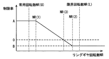
目標駆動力設定部844は、要求駆動力に、図6に示す制限率を乗じて、オートマチックトランスミッション400から駆動輪である後輪700に伝達される駆動力の目標値である目標駆動力を設定する。目標駆動力を設定することにより、オートマチックトランスミッション400から後輪700に伝達されるトルクの目標値である目標トルクが設定される。
The target driving
制限率は、リングギヤ回転数NRに応じて定められる。リングギヤ回転数NRがしきい値NR(1)未満の領域においては、制限率がA(Aは正値)%に定められる。リングギヤ回転数NRがしきい値NR(2)以上の領域においては、制限率がB(Bは負値)%に定められる。 The limiting rate is determined according to the ring gear rotation speed NR. In the region where the ring gear rotation speed NR is less than the threshold value NR (1), the limiting rate is set to A (A is a positive value)%. In a region where the ring gear rotation speed NR is equal to or greater than the threshold value NR (2), the limiting rate is set to B (B is a negative value)%.
しきい値NR(1)は、実験およびシミュレーションなどにより予め定められる常用回転数NR(U)に対してマージンを持って定められる。同様に、しきい値NR(2)は、実験およびシミュレーションなどにより予め定められる限界回転数NR(L)に対してマージンを持って定められる。 The threshold value NR (1) is determined with a margin with respect to the normal rotational speed NR (U) determined in advance by experiments and simulations. Similarly, threshold value NR (2) is determined with a margin with respect to limit rotational speed NR (L) determined in advance by experiments and simulations.
リングギヤ回転数NRがしきい値NR(1)以上、しきい値NR(2)未満の領域において、制限率は線形補間して定められる。そのため、リングギヤ回転数がしきい値NR(3)以上の領域においては、制限率が負値になる。なお、制限率を設定する方法はこれに限らない。 In the region where the ring gear rotation speed NR is equal to or greater than the threshold value NR (1) and less than the threshold value NR (2), the limiting rate is determined by linear interpolation. Therefore, the limiting rate is a negative value in a region where the ring gear rotation speed is equal to or greater than threshold value NR (3). Note that the method of setting the limiting rate is not limited to this.
駆動力制御部846は、オートマチックトランスミッション400から駆動輪である後輪700に伝達される駆動力が目標駆動力になるように、エンジン200、第1MG311、第2MG312を制御する。すなわち、オートマチックトランスミッション400から後輪700に伝達されるトルクが目標トルクになるように、エンジン200、第1MG311、第2MG312が制御される。
The driving
目標駆動力、すなわち目標トルクが正値である場合、リングギヤ328に作用する力の方向が、リングギヤ回転数NRが増加する方向になるように、エンジン200、第1MG311および第2MG312が制御される。
When the target driving force, that is, the target torque is a positive value,
目標駆動力、すなわち目標トルクが負値である場合、リングギヤ328に作用する力の方向が、リングギヤ回転数NRが減少する方向になるように、エンジン200、第1MG311および第2MG312が制御される。
When the target driving force, that is, the target torque is a negative value,
なお、オートマチックトランスミッション400から後輪700に伝達される駆動力が目標駆動力になるように、エンジン200、第1MG311、第2MG312を制御する方法は、ハイブリッド車の技術分野において周知の技術を利用すればよいため、ここではその詳細な説明は繰返さない。
As a method for controlling
前述したように、リングギヤ回転数NRがしきい値NR(3)以上の領域においては、制限率が負値になる。したがって、リングギヤ回転数NRがしきい値NR(3)以上の領域においては、目標駆動力が負値になる。そのため、リングギヤ回転数NRがしきい値NR(3)以上の領域においては、リングギヤ回転数NRが減少する方向へリングギヤ328に力が作用する。
As described above, in the region where the ring gear rotational speed NR is equal to or greater than the threshold value NR (3), the limiting rate is a negative value. Therefore, the target driving force is a negative value in a region where the ring gear rotational speed NR is equal to or greater than the threshold value NR (3). Therefore, in a region where the ring gear rotational speed NR is equal to or greater than the threshold value NR (3), a force acts on the
図7を参照して、本実施の形態に係る制御装置であるECU800が実行するプログラムの制御構造について説明する。なお、以下に説明するプログラムは予め定められた周期で繰り返し実行される。
With reference to FIG. 7, a control structure of a program executed by
ステップ(以下、ステップをSと略す)100にて、ECU800は、アクセル開度、シフトポジションおよび車速に基づいて、要求駆動力を設定する。要求駆動力を設定することにより、要求トルクが設定される。
In step (hereinafter, step is abbreviated as S) 100,
S110にて、ECU800は、入力軸回転数センサ822から送信された信号に基づいて、リングギヤ回転数NRを検出する。S120にて、ECU800は、リングギヤ回転数NRに基づいて、駆動力の制限率を設定する。S130にて、ECU800は、要求駆動力に制限率を乗じて目標駆動力を設定する。目標駆動力を設定することにより、目標トルクが設定される。
In S110,
S140にて、ECU800は、オートマチックトランスミッション400から駆動輪である後輪700に伝達される駆動力が目標駆動力になるように、エンジン200、第1MG311、第2MG312を制御する。すなわち、オートマチックトランスミッション400から後輪700に伝達される駆動力が目標トルクになるように、エンジン200、第1MG311、第2MG312が制御される。
In S140,
以上のような構造およびフローチャートに基づく、本実施の形態に係る制御装置であるECU800の動作について説明する。
An operation of
車両の走行中、アクセル開度、シフトポジションおよび車速に基づいて、要求駆動力が設定される(S100)。また、リングギヤ回転数NRが検出される(S110)。リングギヤ回転数NRに基づいて、駆動力の制限率が設定される(S120)。要求駆動力に制限率を乗じて目標駆動力が設定される(S130)。 While the vehicle is traveling, the required driving force is set based on the accelerator opening, the shift position, and the vehicle speed (S100). Further, the ring gear rotational speed NR is detected (S110). Based on the ring gear rotation speed NR, a driving force limiting rate is set (S120). The target driving force is set by multiplying the required driving force by the limiting rate (S130).
オートマチックトランスミッション400から駆動輪である後輪700に伝達される駆動力が目標駆動力になるように、エンジン200、第1MG311、第2MG312が制御される(S140)。これにより、ハイブリッド車が運転者の要求に応じて走行する。
The
ところで、たとえば故障もしくは運転者がアクセル操作をした状態でシフト操作を行なったことにより、オートマチックトランスミッション400がニュートラル状態になった場合、オートマチックトランスミッション400の入力軸404に連結されたリングギヤ328は自由回転可能になる。そのため、図8に示すように、リングギヤ回転数NRが急増する。その結果、リングギヤ回転数NRが過剰になり得る。
By the way, for example, when the
そこで、本実施の形態においては、図9に示すように、リングギヤ回転数NRがしきい値NR(3)を超えると、駆動力の制限率が負値に設定される。したがって、目標駆動力、すなわち目標トルクが負値になる。これにより、第2MG312を発電機として作動したり、エンジン200における燃料噴射を停止(フューエルカットを実行)したりして、リングギヤ328に作用する力の方向を、リングギヤ回転数NRが減少する方向にすることができる。そのため、リングギヤ回転数NRが過剰にならないようにすることができる。
Therefore, in the present embodiment, as shown in FIG. 9, when the ring gear rotation speed NR exceeds the threshold value NR (3), the driving force limiting rate is set to a negative value. Therefore, the target driving force, that is, the target torque becomes a negative value. Thus, the
以上のように、本実施の形態に係る制御装置であるECUによれば、オートマチックトランスミッションから駆動輪である後輪に伝達される駆動力が目標駆動力になるように、ハイブリッドシステムのエンジン、第1MG、第2MGが制御される。リングギヤ回転数NRがしきい値NR(3)以上である領域においては、目標駆動力が負値に設定される。これにより、リングギヤに作用する力の方向を、リングギヤ回転数NRが減少する方向にすることができる。そのため、リングギヤ回転数NRが過剰にならないようにすることができる。 As described above, according to the ECU that is the control device according to the present embodiment, the engine of the hybrid system, the first, so that the driving force transmitted from the automatic transmission to the rear wheel that is the driving wheel becomes the target driving force. 1MG and 2nd MG are controlled. In the region where the ring gear rotation speed NR is equal to or greater than the threshold value NR (3), the target driving force is set to a negative value. Thereby, the direction of the force acting on the ring gear can be set to a direction in which the ring gear rotation speed NR decreases. Therefore, it is possible to prevent the ring gear rotation speed NR from becoming excessive.
なお、本実施の形態においては、リングギヤ回転数NRがしきい値NR(3)以上である領域においては、目標駆動力、すなわち目標トルクを負値に設定していたが、リングギヤ回転数NRがオートマチックトランスミッション400の出力軸回転数NOよりも大きい場合に目標駆動力を負値に設定するようにしてもよい。
In the present embodiment, in the region where the ring gear rotational speed NR is equal to or greater than the threshold value NR (3), the target driving force, that is, the target torque is set to a negative value, but the ring gear rotational speed NR is When the output shaft rotational speed NO of the
今回開示された実施の形態は、すべての点で例示であって制限的なものではないと考えられるべきである。本発明の範囲は上記した説明ではなくて特許請求の範囲によって示され、特許請求の範囲と均等の意味および範囲内でのすべての変更が含まれることが意図される。 The embodiment disclosed this time should be considered as illustrative in all points and not restrictive. The scope of the present invention is defined by the terms of the claims, rather than the description above, and is intended to include any modifications within the scope and meaning equivalent to the terms of the claims.
100 ハイブリッドシステム、200 エンジン、310 動力分割機構、311 第1MG、312 第2MG、320 プラネタリギヤ、322 サンギヤ、324 ピニオンギヤ、326 キャリア、328 リングギヤ、400 オートマチックトランスミッション、404 入力軸、406 出力軸、431 C1クラッチ、432 C2クラッチ、433 C3クラッチ、441 B1ブレーキ、442 B2ブレーキ、450 ワンウェイクラッチ(F)、500 プロペラシャフト、600 デファレンシャルギヤ、700 後輪、800 ECU、802 ROM、804 シフトレバー、806 ポジションスイッチ、808 アクセルペダル、810 アクセル開度センサ、812 ブレーキペダル、814 ストロークセンサ、816 電子スロットルバルブ、818 スロットル開度センサ、820 エンジン回転数センサ、822 入力軸回転数センサ、824 出力軸回転数センサ、826 油温センサ、828 水温センサ、840 リングギヤ回転数検出部、842 要求駆動力設定部、844 目標駆動力設定部、846 駆動力制御部。 100 hybrid system, 200 engine, 310 power split mechanism, 311 1st MG, 312 2nd MG, 320 planetary gear, 322 sun gear, 324 pinion gear, 326 carrier, 328 ring gear, 400 automatic transmission, 404 input shaft, 406 output shaft, 431 C1 clutch 432 C2 clutch, 433 C3 clutch, 441 B1 brake, 442 B2 brake, 450 one-way clutch (F), 500 propeller shaft, 600 differential gear, 700 rear wheel, 800 ECU, 802 ROM, 804 shift lever, 806 position switch, 808 Accelerator pedal, 810 Accelerator opening sensor, 812 Brake pedal, 814 Stroke sensor, 816 Electronic throttle valve, 818 throttle opening sensor, 820 engine speed sensor, 822 input shaft speed sensor, 824 output shaft speed sensor, 826 oil temperature sensor, 828 water temperature sensor, 840 ring gear speed sensor, 842 required driving force Setting unit, 844 Target driving force setting unit, 846 Driving force control unit.
Claims (6)
前記第2の回転要素に作用する力の方向を、前記切換機構から前記車輪に伝達されるトルクの目標値が正値である場合には前記第2の回転要素の回転数が増加する方向にし、前記目標値が負値である場合には前記第2の回転要素の回転数が減少する方向にするように、前記第1の回転電機、前記第2の回転電機および前記エンジンを制御するための手段と、
前記第2の回転要素の回転数を検出するための手段と、
前記第2の回転要素の回転数がしきい値より大きい場合に前記目標値を負値に設定するための設定手段とを含む、パワートレーンの制御装置。 A differential mechanism having a first rotating element coupled to the first rotating electrical machine, a second rotating element coupled to the second rotating electrical machine, and a third rotating element coupled to the engine; A switching mechanism that is connected to the rotating element and is capable of switching between a state in which torque input from the second rotating element is transmitted to the wheel and a state in which transmission of torque from the second rotating element to the wheel is interrupted. A power train control device comprising:
The direction of the force acting on the second rotating element is set to a direction in which the rotation speed of the second rotating element increases when the target value of torque transmitted from the switching mechanism to the wheel is a positive value. In order to control the first rotating electric machine, the second rotating electric machine, and the engine so that the rotation speed of the second rotating element is decreased when the target value is a negative value. Means of
Means for detecting the rotational speed of the second rotating element;
And a setting means for setting the target value to a negative value when the rotation speed of the second rotation element is greater than a threshold value.
前記第2の回転要素に作用する力の方向を、前記切換機構から前記車輪に伝達されるトルクの目標値が正値である場合には前記第2の回転要素の回転数が増加する方向にし、前記目標値が負値である場合には前記第2の回転要素の回転数が減少する方向にするように、前記第1の回転電機、前記第2の回転電機および前記エンジンを制御するステップと、
前記第2の回転要素の回転数を検出するステップと、
前記第2の回転要素の回転数がしきい値より大きい場合に前記目標値を負値に設定するステップとを含む、パワートレーンの制御方法。 A differential mechanism having a first rotating element coupled to the first rotating electrical machine, a second rotating element coupled to the second rotating electrical machine, and a third rotating element coupled to the engine; A switching mechanism that is connected to the rotating element and is capable of switching between a state in which torque input from the second rotating element is transmitted to the wheel and a state in which transmission of torque from the second rotating element to the wheel is interrupted. A power train control method comprising:
The direction of the force acting on the second rotating element is set to a direction in which the rotation speed of the second rotating element increases when the target value of torque transmitted from the switching mechanism to the wheel is a positive value. And, when the target value is a negative value, controlling the first rotating electric machine, the second rotating electric machine, and the engine so as to reduce the rotation speed of the second rotating element. When,
Detecting the number of revolutions of the second rotating element;
And a step of setting the target value to a negative value when the rotation speed of the second rotation element is greater than a threshold value.
Priority Applications (1)
| Application Number | Priority Date | Filing Date | Title |
|---|---|---|---|
| JP2007042785A JP4390814B2 (en) | 2007-02-22 | 2007-02-22 | Powertrain control device, control method, program for realizing the method, and recording medium recording the program |
Applications Claiming Priority (1)
| Application Number | Priority Date | Filing Date | Title |
|---|---|---|---|
| JP2007042785A JP4390814B2 (en) | 2007-02-22 | 2007-02-22 | Powertrain control device, control method, program for realizing the method, and recording medium recording the program |
Publications (2)
| Publication Number | Publication Date |
|---|---|
| JP2008201381A JP2008201381A (en) | 2008-09-04 |
| JP4390814B2 true JP4390814B2 (en) | 2009-12-24 |
Family
ID=39779297
Family Applications (1)
| Application Number | Title | Priority Date | Filing Date |
|---|---|---|---|
| JP2007042785A Expired - Fee Related JP4390814B2 (en) | 2007-02-22 | 2007-02-22 | Powertrain control device, control method, program for realizing the method, and recording medium recording the program |
Country Status (1)
| Country | Link |
|---|---|
| JP (1) | JP4390814B2 (en) |
-
2007
- 2007-02-22 JP JP2007042785A patent/JP4390814B2/en not_active Expired - Fee Related
Also Published As
| Publication number | Publication date |
|---|---|
| JP2008201381A (en) | 2008-09-04 |
Similar Documents
| Publication | Publication Date | Title |
|---|---|---|
| JP4349416B2 (en) | Powertrain control device, control method, program for realizing the method, and recording medium recording the program | |
| JP6003592B2 (en) | Vehicle control device | |
| JP4305522B2 (en) | Powertrain control device | |
| JP2008189141A (en) | Control apparatus and control method for power transmission apparatus | |
| JP2011037331A (en) | Power train for vehicle | |
| JP4940991B2 (en) | Powertrain control device, control method, program for realizing the method, and recording medium recording the program | |
| JP4224098B2 (en) | Powertrain control device, control method, program for realizing the method, and recording medium recording the program | |
| JP4786553B2 (en) | Rotational speed prediction apparatus, prediction method, program for realizing the method, and recording medium recording the program | |
| JP2010065697A (en) | Method for controlling internal combustion engine for drive train of automobile and control device | |
| JP2011161975A (en) | Power train of vehicle | |
| JP2008189243A (en) | Control apparatus and control method for power train, program for implementing the method, and recording medium with the program recorded thereon | |
| JP4390814B2 (en) | Powertrain control device, control method, program for realizing the method, and recording medium recording the program | |
| JP2010149707A (en) | Power train of vehicle | |
| JP4909118B2 (en) | Automatic transmission shift determination device, shift determination method, program for realizing the method, and recording medium recording the program | |
| JP2008162348A (en) | Apparatus and method for controlling power train, program for implementing the method, and recording medium with the program recorded | |
| JP2008168810A (en) | Control device and method of power train, program for realizing method, and recording medium with program recorded thereon | |
| JP4909134B2 (en) | Powertrain control device, control method, program for realizing the method, and recording medium recording the program | |
| JP5212308B2 (en) | Vehicle power train | |
| JP4845780B2 (en) | Powertrain control device, control method, program for realizing the method, and recording medium recording the program | |
| JP2009190436A (en) | Control device of vehicle | |
| JP5942786B2 (en) | Vehicle creep torque control device | |
| JP2008280968A (en) | Control device for vehicle, control method, program materializing method thereof, and recording medium recording program thereof | |
| JP4751843B2 (en) | Powertrain control device, control method, program for realizing the method, and recording medium recording the program | |
| JP5029398B2 (en) | Vehicle control device | |
| JP2008128204A (en) | Control device and control method for vehicle, program for implementing the method, and recording medium recording the program |
Legal Events
| Date | Code | Title | Description |
|---|---|---|---|
| A711 | Notification of change in applicant |
Free format text: JAPANESE INTERMEDIATE CODE: A711 Effective date: 20081031 |
|
| A521 | Written amendment |
Free format text: JAPANESE INTERMEDIATE CODE: A821 Effective date: 20081031 |
|
| A131 | Notification of reasons for refusal |
Free format text: JAPANESE INTERMEDIATE CODE: A131 Effective date: 20081216 |
|
| TRDD | Decision of grant or rejection written | ||
| A01 | Written decision to grant a patent or to grant a registration (utility model) |
Free format text: JAPANESE INTERMEDIATE CODE: A01 Effective date: 20090929 |
|
| A01 | Written decision to grant a patent or to grant a registration (utility model) |
Free format text: JAPANESE INTERMEDIATE CODE: A01 |
|
| A61 | First payment of annual fees (during grant procedure) |
Free format text: JAPANESE INTERMEDIATE CODE: A61 Effective date: 20091006 |
|
| FPAY | Renewal fee payment (event date is renewal date of database) |
Free format text: PAYMENT UNTIL: 20121016 Year of fee payment: 3 |
|
| R151 | Written notification of patent or utility model registration |
Ref document number: 4390814 Country of ref document: JP Free format text: JAPANESE INTERMEDIATE CODE: R151 |
|
| FPAY | Renewal fee payment (event date is renewal date of database) |
Free format text: PAYMENT UNTIL: 20121016 Year of fee payment: 3 |
|
| FPAY | Renewal fee payment (event date is renewal date of database) |
Free format text: PAYMENT UNTIL: 20121016 Year of fee payment: 3 |
|
| FPAY | Renewal fee payment (event date is renewal date of database) |
Free format text: PAYMENT UNTIL: 20131016 Year of fee payment: 4 |
|
| R250 | Receipt of annual fees |
Free format text: JAPANESE INTERMEDIATE CODE: R250 |
|
| R250 | Receipt of annual fees |
Free format text: JAPANESE INTERMEDIATE CODE: R250 |
|
| R250 | Receipt of annual fees |
Free format text: JAPANESE INTERMEDIATE CODE: R250 |
|
| R250 | Receipt of annual fees |
Free format text: JAPANESE INTERMEDIATE CODE: R250 |
|
| R250 | Receipt of annual fees |
Free format text: JAPANESE INTERMEDIATE CODE: R250 |
|
| R250 | Receipt of annual fees |
Free format text: JAPANESE INTERMEDIATE CODE: R250 |
|
| R250 | Receipt of annual fees |
Free format text: JAPANESE INTERMEDIATE CODE: R250 |
|
| R250 | Receipt of annual fees |
Free format text: JAPANESE INTERMEDIATE CODE: R250 |
|
| LAPS | Cancellation because of no payment of annual fees |