JP4390328B2 - Magnetic resonance imaging system - Google Patents
Magnetic resonance imaging system Download PDFInfo
- Publication number
- JP4390328B2 JP4390328B2 JP29657299A JP29657299A JP4390328B2 JP 4390328 B2 JP4390328 B2 JP 4390328B2 JP 29657299 A JP29657299 A JP 29657299A JP 29657299 A JP29657299 A JP 29657299A JP 4390328 B2 JP4390328 B2 JP 4390328B2
- Authority
- JP
- Japan
- Prior art keywords
- echo
- phase
- measurement
- magnetic field
- echo signal
- Prior art date
- Legal status (The legal status is an assumption and is not a legal conclusion. Google has not performed a legal analysis and makes no representation as to the accuracy of the status listed.)
- Expired - Fee Related
Links
Images


Landscapes
- Magnetic Resonance Imaging Apparatus (AREA)
Description
【0001】
【発明の属する技術分野】
本発明は、被検体中の水素や燐等からの核磁気共鳴(以下、「NMR」という)信号を測定し、核の密度分布や緩和時間分布等を映像化する磁気共鳴イメージング(MRI)装置に関し、特にエコー信号間の位相変化により生じるアーチファクトを効果的に抑制することを可能としたMRI装置に関する。
【0002】
【従来の技術】
MRIを用いた撮像方法では、一般に読み出し傾斜磁場の反転を利用してNMR信号をエコーとして計測する方法が用いられる。エコー信号は一定のサンプリング時間計測して所定サンプリング数の時系列データとする。ところでエコー信号は、例えば正極性の読み出し傾斜磁場の印加時間と印加強度の積(積分値)と負極性の読み出し傾斜磁場の印加時間と印加強度の積とが一致するところで発生する、即ち両者が一致した時点でエコーはピークとなるので、サンプリング時間はこのピークとなる時点を中心として設定される。
【0003】
しかし、MRI装置ではこのように計測したエコー信号が計測空間の中央からずれる場合がある。これは永久磁石や超電導磁石等の静磁場発生装置によって高度の静磁場均一性が保たれていても、測定対象である被検体の磁化率によって磁場のオフセットが変化することや、傾斜磁場パルスの不完全性や出力応答の誤差等による。
【0004】
撮像方法として1回或いは数回のRF照射で1枚の画像再構成に必要なエコー信号を取得するシングルショット或いはマルチショットのエコープレナーイメージング(EPI)法がある。この撮像方法では、読み出し傾斜磁場を反転しながら時系列的に複数のエコー信号を取得するので、これら複数のエコーを計測空間に配置した場合、偶数エコーと奇数エコーではエコーのピークがそれぞれ異なった位置となる。
【0005】
図9(a)はこの様子を模式的に示したものであり、例えば、奇数エコーの時系列データを図示する計測空間901の左から順に配置するとすると、偶数エコーは計測空間の右から配置することになる。従って奇数エコーのピーク位置9021,9022・・・が計測空間中央904から左側にずれた場合、偶数エコーのピーク位置9031,9032・・・は計測空間中央904に対し右側にずれる。
【0006】
このようなデータを読み出し方向のフーリエ変換すると、偶数エコー、奇数エコーで位相の変化が逆になるため、図9(b)のようなアーチファクト905が画像領域906の両側に生じる。これは一般にN/2アーチファクトと呼ばれる。
【0007】
このようなN/2アーチファクトを信号処理によって除去する手法が提案されている(特開平8-215174号、特開平5-68674号など)。これらの方法では、被検体の画像形成のための撮影(本計測)に先立って、位相エンコード傾斜磁場を加えない状態で、あらかじめ静磁場補正用のデータを取得しておき、この補正用データを用いて計測したエコー信号(本計測データ)を補正する。
【0008】
例えば、特開平8-215174号公報に記載された方法では、補正用データとして一組の偶数エコー、奇数エコーを取得し、これらエコーをフーリエ変換した後に、エコー間の位相差を求め、本計測データを補正する。また、特開平5-68674号公報に記載された方法では、補正用データ及び本計測データをそれぞれ読み出し方向に1次元フーリエ変換し、本計測データから補正用データの位相を減算することにより補正する。
【0009】
【発明が解決しようとする課題】
しかし特開平8-215174号公報に記載された補正方法では、計測空間における位相エンコード方向の位相変化までは考慮されていなかった。即ち、エコートレイン(1回の励起内で連続して計測される複数のエコー)内で傾斜磁場の渦電流などにより位相差が異なる場合があるが、このような変化は上述した補正方法では考慮されていない。特開平5-68674号公報に記載された方法では、位相エンコード方向のオフセットが最適に調整されていない場合、図10(a)で示すように補正用エコー信号を一次元フーリエ変換した補正用データ1001,1002・・・の位相にノイズ的な変化1011,1012が混入することがある。このような補正用データを用いて補正した画像1020には、(b)に示すように線状のアーチファクト(ストリークアーチファクト)1031,1032が生じる。また、補正用データの位相に2次的な変化も混入していることがあるため、補正後の画像が図中、1041,1042で示すような歪みが生じる場合もある。
【0010】
そこで本発明は、位相エンコード方向のオフセットや2次的に混入位相ノイズも含めた補正が可能であり、高精度でN/2アーチファクトを低減したMR画像を得ることを目的とする。
【0011】
【課題を解決するための手段】
上記目的を達成するため、本発明では少なくとも1回の繰り返し時間内で計測する本計測エコーに対応する数の前計測エコーを得て、時間的に隣接する前計測エコーについてそれぞれ位相変化を算出し、本計測エコーの位相エンコード方向の位相変化を反映した補正用位相マップを作成する。また得られた位相差(位相変化)について、その精度を向上する処理を施す。このような補正用位相マップを用いて本計測エコーを補正あるいはパルスシーケンスを調整することにより、N/2アーチファクトを高精度で除去することができる。
【0012】
即ち、本発明のMRI装置は、被検体に高周波パルスを照射する手段と、読み出し傾斜磁場パルスを印加する手段と、位相エンコード傾斜磁場パルスを印加する手段と、少なくとも1回の繰り返し時間内で発生するエコー信号を時系列的に検出する手段と、エコー信号から画像を作成し、表示する手段と、所定のパルスシーケンスに従い前記各手段を制御する制御手段とを有するMRI装置において、前記制御手段は、画像取得のための本計測エコー信号とは別に、位相エンコード傾斜磁場パルスを印加せずに少なくとも1回の繰り返し時間内で計測した前計測エコー信号を用いて、各前計測エコー信号間の位相変化をそれぞれ算出し、それぞれの位相変化を用いて補正用位相マップを作成するとともに、前記補正用位相マップを用いて本計測エコー信号を取得するためのパルスシーケンスのエコー計測時間を調整する手段を有する。
【0013】
また本発明のMRI装置は、前記制御手段が、画像取得のための本計測エコー信号とは別に、位相エンコード傾斜磁場パルスを印加せずに少なくとも1回の繰り返し時間内で計測した前計測エコー信号を用いて、各前計測エコー信号間の位相変化をそれぞれ算出し、それぞれの位相変化を用いて補正用位相マップを作成するとともに、少なくとも1回の繰り返し時間内で計測した本計測エコー信号をそれぞれ前記補正用位相マップの対応する補正データを用いて補正する手段を有する。
【0014】
本発明のMRI装置では、連続して計測される複数のエコー信号のそれぞれについて位相変化を算出し、補正用位相マップを作成するので、位相エンコード方向に位相変化がある場合でも精度よく補正することができる。
【0015】
また本発明のMRI装置は、均一磁場空間を形成するための静磁場を発生する静磁場発生手段と、均一磁場空間に置かれた被検体に対し高周波パルスを照射する高周波パルス発生手段と、前記被検体に対しスライス方向、位相エンコード方向および読み出し方向の各傾斜磁場を印加する傾斜磁場発生手段と、前記被検体からのエコー信号を検出する検出手段と、前記エコー信号から画像を再構成する画像処理手段と、得られた画像を表示する画像表示手段と、所定のシーケンスに従い高周波パルス発生手段、傾斜磁場発生手段の発生タイミングを制御するとともに検出手段、画像処理手段、画像表示手段をそれぞれ制御する制御手段とを備えたMRI装置において、前記制御手段は、位相エンコードを印加しない前計測シーケンスの後に位相エンコードを付加した本計測シーケンスを実行するよう制御し、前記シーケンスにおいて、少なくとも1回の繰り返し時間内で連続的に計測した前計測エコー信号を用いて、各前計測エコー信号間の位相変化をそれぞれ算出するとともに、計測空間上に時系列に配置される本計測エコー信号を対応する前記位相変化の情報に基づいて、偶数番目取得の本計測エコー信号の位相を奇数番目取得の本計測エコー信号の位相に揃える、奇数番目取得の本計測エコー信号の位相を偶数番目取得の本計測エコー信号の位相に揃える、もしくは計測中心の位相に揃える、のいずれかの処理を実行する位相補正手段を備えたことを特徴とする。
【0016】
本発明の好適な態様のMRI装置は、補正用位相マップの作成において、算出した位相変化の精度を向上する処理を含む。これら処理は、具体的には、主値回り補正、位相差の平均処理を含む。
【0017】
【発明の実施の形態】
以下、本発明のMRI装置について、図面を参照して詳述する。
【0018】
図8は本発明が適用されるMRI装置の全体構成を示す図で、このMRI装置は、被検体801を囲む所定の空間に静磁場を発生する磁石802と、該空間に傾斜磁場を発生する傾斜磁場コイル803と、この空間に高周波磁場を発生するRFコイル804と、被検体801が発生するMR信号を検出するRFプローブ805とを備えている。ベッド812は被検体が横たわるためのものである。
【0019】
傾斜磁場コイル803は、X、Y、Zの3方向の傾斜磁場コイルで構成され、傾斜磁場電源809からの信号に応じてそれぞれ傾斜磁場を発生する。傾斜磁場には、被検体の所定のスライスを選択するために印加されるスライス選択傾斜磁場、エコー信号を位相エンコードするために印加される位相エンコード傾斜磁場およびエコー信号に周波数エンコードするとともにグラディエントエコーを発生させるための読み出し傾斜磁場があり、本発明においては極性の反転する読み出し傾斜磁場を使用する。
【0020】
RFコイル804はRF送信部810の信号に応じて高周波磁場を発生する。RFプローブ805の信号は、信号検出部806で検出され、信号処理部807で信号処理され、また計算により画像信号に変換される。画像は表示部808で表示される。
【0021】
傾斜磁場電源809、RF送信部810、信号検出部806は、一般にパルスシーケンスと呼ばれるタイムチャートに従い制御部811で制御される。
【0022】
制御部811は、上述した信号処理部807で信号処理されたデジタル信号であるエコー信号に各種演算を行うとともに、反転する読み出し傾斜磁場の各周期内で発生するエコー信号を用いて位相変化の算出、補正用位相マップの作成、補正用位相マップを用いたパルスシーケンスの調整および/または補正用位相マップを用いた本計測エコーの補正などを行う機能を備えている。これら制御部811の各機能は、制御部811を構成するコンピュータのプログラムとして構築される。
【0023】
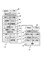
次に、このような構成における本発明の第1の実施形態を説明する。この実施形態では、図1に示すように本計測200に先だって前計測シーケンス100を実行し、この前計測シーケンスで得た補正用エコー101を用いて本計測シーケンスのサンプリング時間を調整する。
【0024】
本計測シーケンスは、シングルショット或いはマルチショットのEPIシーケンスであり、高周波パルスにより被検体の所定領域を励起した後、連続して反転する読み出し傾斜磁場を印加しながら、これと同時に位相エンコード傾斜磁場を印加して、位相エンコードの異なる複数のエコ―信号を計測する。位相エンコードの数は通常1枚の画像あたり64、128、256、512等の値が選ばれる。シングルショットEPIでは、これら位相エンコードの異なる信号を一度の励起で計測し、マルチショットEPIでは分割して計測する。各エコー信号は通常128、256、512、1024個のサンプリングデータからなる時系列信号として得られる。
【0025】
以下、本計測シーケンスがマルチショットEPIである場合を例にして説明する。図2は補正前の本計測シーケンスを示す図で、このパルスシーケンスでは高周波パルス201とスライス選択傾斜磁場パルス202を印加した後、位相エンコードのオフセットを与えるパルス203と読み出し傾斜磁場のオフセットを与えるパルス204を印加し、位相エンコード傾斜磁場パルス205を離散的に印加しながら反転する読み出し傾斜磁場206の各周期内で各位相エンコードのエコー信号102が発生するので、これをサンプリング時間207の間おのおのサンプリングし時系列データ102を得る。サンプリング時間207は典型的にはそれぞれ1ms程度である。
【0026】
このようなシーケンス208を複数回(N回)繰り返し、画像再構成に必要な全ての本計測エコ-信号h(n,m,t)102を取得する。なお、nは繰り返し番号(1≦n≦N)、mはエコー番号(1≦m≦M)、t は時間を表す。一例として、1回の高周波パルス印加で計測する本計測エコー信号の数が16(M=16)であり、読み出し方向のデータ数が128(x=128)、位相エンコード方向のエンコード数が128であるとすると、1枚の画像を得るのに必要な繰り返し数は8(N=8)となる。
【0027】
既に述べたようにこのように計測された本計測エコーは、エコーのピーク位置がサンプリング時間207の中心と一致しないために、計測空間において奇数番目(mが奇数)のエコーのピーク位置と、偶数番目(mが偶数)のエコーのピーク位置が計測空間中央に対し、それぞれ逆方向にずれる(図9(a))。
【0028】
この計測空間におけるエコー信号のピークずれは、フーリエ変換後の空間での位相変化に対応する。そこで、まず前計測によって奇数エコーと偶数エコーの位相変化を求め、この位相変化からピーク位置のずれを求め、奇数エコーおよび偶数エコーのピーク位置を一致するように本計測シーケンスにおけるサンプリング時間を調整する。
【0029】
図3はこのような位相検出ための前計測パルスシーケンスの一例を示す図であり、本計測シーケンスに対応してマルチショットEPIシーケンスを基本としている。但し、図3のパルスシーケンスは位相エンコード傾斜磁場を加えない点が本計測のEPIシーケンスとは異なる。
【0030】
即ち、まず検知する磁化を含む被検体に高周波パルス201を照射すると同時にスライスを選択する傾斜磁場パルス202を印加し、画像化するスライスを選択する。次いで読み出し傾斜磁場のオフセットを与えるパルス204を印加した後、連続して反転する読み出し傾斜磁場パルス206を印加し、反転する読み出し傾斜磁場206の各周期内でエコー信号101が時系列的に発生するので、これを時間範囲207の間おのおのサンプリングし時系列データ101を得る。反転する読み出し傾斜磁場206の強度、印加タイミング、時間範囲207は本計測シーケンスと同じである。
【0031】
このようにシーケンス208内で取得された時系列データ101、即ち前計測エコ-信号p(m,t)101を用いて位相差マップを作成する。なお、mはエコー番号(1≦m≦M)、tは時間を表す。このため、まず前計測エコー信号p(m,t)101を読み出し方向にフーリエ変換し、補正用データp(m,x)105を取得する(ステップ103)。ここで、xは読み出し方向の位置を表し、1≦x≦Xである。
【0032】
次いで偶数エコーの補正用データと奇数エコーの補正用データとから両者間の位相差s(k,x)108 を計算する(ステップ107)。具体的には、下記計算を行う。
【0033】
【数1】

【0034】
次に位相差s(k,x)の精度を向上するための処理(109,110)を行う。上式からもわかるようにこの計算は、-π〜+πの範囲でなされるため、-πを超えるものは折り返して+πの方へ、+πを超えるものは折り近して-πの方へそれぞれ値が離散的に変化する(これを主値回りといい、局所的に位相が主値回りするものを主値飛びという)。上述のように求めた位相差s(k,x)には、この主値飛びノイズが混入しているため、これを下記計算により除去をする(ステップ109)。
【0035】
【数2】
【0036】
さらに主値飛びノイズ以外に位相差に混入するノイズを除去するため、下式により位相差を平均する(ステップ110)。
【0037】
【数3】
【0038】
これらの処理109、110によりピークずれの検出の精度を向上することができる。
【0039】
次にこのように求めた位相差マップを用いて本計測シーケンスにおけるサンプリング時間207を設定する。図4は、エコー信号のピークの計測空間中央からのずれと位相変化との関係を示したものであり、図示するように、エコー信号402のピークが計測空間の中央401にあるときには、エコーを一次元フーリエ変換した空間での位相の変化は、直線405で示すように0であるが、エコー信号403のピークが中央401からずれたときには(ずれ量404)、このエコー信号を一次元フーリエ変換した空間では、位相は一次関数的に直線406のように変化する。従って位相変化の傾きを求めることによって、ずれ量(時間)を求めることができる。
【0040】
このため、ステップ110により作成した位相差s'(k,x)をフィッティング処理して位相変化の傾き(1次成分)を計算する(ステップ111)。フィッティングとして、例えば最小2乗法を採用できる。このようなフィッティングを位相差s'(k,x)の全てのkについて行う。
【0041】
ステップ111でs'(k,x)の各kについて求めた傾きa(k)から次式によりサンプリング時間207のずれΔt(k)112を計算する。
【0042】
【数4】
【0043】
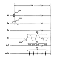
次に、求めたΔt(k)から、本計測シーケンスのエコー計測時間を計算する(ステップ113)。具体的には、図2の本計測シーケンスにおいて奇数番めのエコーのサンプリング時間はそのままにして、偶数番目のエコーのサンプリング開始時間をΔt(k)ずらす。このように調整された本計測シーケンスを図5に示す。ここでは本計測シーケンス中、読み出し傾斜磁場(Gr)、サンプリング(A/D)、発生したエコー信号(echo)についてのみ示した。
【0044】
図示するように、エコー信号102はそのピーク位置が計測空間中心から 501(5011,5012・・・)だけずれている。このずれ501は、上述の計算によって求めたΔt(k)/2に対応する。そこで、偶数番目のエコーのサンプリング時間207を、Δt(k) (502)だけずらす。これにより計測空間のエコー信号のピーク位置がそろうことになる。
【0045】
このようにステップ103から113までの前計測処理114で計算した本計測シーケンスを実行し、本計測エコー信号102 を取得する。図6に取得した本計測エコー102の計測空間601の配列を示す。図示するように、偶数エコー602のピーク6021,6022・・・は、サンプリング時間をずらすことにより、奇数エコー603のピーク6031,6032…と同じ位置になる。これらは全体として計測空間601の中心604からずれているが、各エコーのピークがそろっているため、これを2次元フーリエ変換して画像再構成119を行い作成した画像118ではN/2アーチファクトが大幅に低減される。
【0046】
尚、図6では、計測空間の中心からのずれがエコー番号に関わらず同一である場合を示しているが、上述したように本発明では位相差はエコー番号(k)の関数として求められるので、エコートレイン内で位相差が変化する場合でも正確にピークを揃えることができる。
【0047】
以上、本発明の第1の実施形態を説明した。この実施形態では偶数エコーのサンプリング時間を調整する場合を説明したが、奇数エコーを調整しても良いし、両者を調整することも可能である。またシーケンスについてもマルチショットのみならず、ワンショット型のシーケンスや、マルチスライス、3D計測等に本発明の処理を適用することも可能である。
【0048】
第1の実施形態によるMRI装置によれば、補正用データからエコー間の位相変化を算出し本計測シーケンスをエコー毎にサブピクセル単位で最適に調整するので、画像歪みや線状のアーチファクトを生じることなく、画質の良い撮影を実現できる。
【0049】
また補正用データを用いて画像再構成時に補正処理を行うのではなく、本計測シーケンスを調整しているので、再構成時間を延長することなく本計測を行うことができる。
【0050】
次に、本発明の第2の実施形態を説明する。この実施形態でも、本計測に先だって前計測シーケンスを実行し、エコー毎の補正用データを作成することは第1の実施形態と同様であるが、第2の実施形態では、この補正用データp(m,x)101を用いて本計測シーケンスで計測した各エコーの位相を補正する。
【0051】
図7にこの実施形態による処理の手順を示す。図1と同一の処理については図1と同じ符号で示した。ここでもマルチショットEPIを例にして説明する。まず図2に示す前計測シーケンスを実行し、補正用エコーp(m,t)を計測する(ステップ101)。ここでmはエコー番号、tは時間であり、本計測シーケンスの1繰り返し時間で計測するエコーと同じ数のエコーを計測する。この補正用エコーをエコー毎に読み出し方向にフーリエ変換し、補正用データp(m,x)を得る(ステップ103)。
【0052】
この補正用データから奇数エコーと偶数エコーの間の位相差s(k,x)を計算する(ステップ107)。この計算は、第1の実施形態において位相差s(k,x)を求めた計算と同じである。従って、この場合にも主値飛びノイズの除去(ステップ109)と位相差の平均を求める処理(ステップ110)を行う。このように精度を向上した位相差s'(k,x)は、補正用位相マップとして制御部のメモリに格納される。
【0053】
一方、図2に示す本計測シーケンスを実行し、本計測エコーh(n,m,t)を計測する(ステップ102)。ここでnは繰り返し番号、mはエコー番号、tは時間である。次いで本計測エコーh(n,m,t)を読み出し方向にフーリエ変換し、本計測データh(n,m,x)を得る(ステップ106)。
【0054】
この本計測データを前計測で求めた補正用位相マップs'(k,x)を用いて補正する(ステップ111)。補正の計算は、例えば次式により行う。
【0055】
【数5】
【0056】
このように奇数エコーと偶数エコーの位相を揃えた後、本計測データを位相エンコード方向にフーリエ変換することにより(ステップ112)画像再構成される。このように再構成した画像113ではN/2アーチファクトが大幅に低減される。
【0057】
この実施形態でも位相差はエコー番号(k)の関数として求められ、エコー番号mが異なる本計測エコーについてそれぞれ対応する位相差データを用いて補正するので、位相エンコード方向に位相差の変動がある場合にも、即ち、エコートレイン内で位相差が変化する場合でも、正確に補正することができる。これにより画像歪みや線状のアーチファクトを生じることなく、画質の良い撮影を実現することができる。
【0058】
以上、本発明の第2の実施形態を説明したが、この実施形態も第1の実施形態と同様にワンショットシーケンスやマルチスライス計測、3D計測にも適用することができる。
【0059】
【発明の効果】
本発明は以上のように構成されたので、下記の効果が得られる。
▲1▼全エコーについて、偶数エコー、奇数エコー信号の位相差をそれぞれ計算するので、 エコートレイン内で傾斜磁場の渦電流などにより、上記差がエコー毎に異なっていても、正確に本計測エコーを補正できる。或いは本計測シーケンスを調整できる。
▲2▼読み出し方向フーリエ変換後の補正用データについて、精度を向上する処理を行うので、従来の補正では除去できなかった脳低部などのストリークアーチファクトを除去することができ、画質のよいMR画像を得ることができる。
【図面の簡単な説明】
【図1】本発明のMRI装置の第1の実施形態における処理手順を示す図。
【図2】本発明のMRI装置で実行される本計測パルスシーケンスの一例を示す図。
【図3】本発明のMRI装置で実行される前計測のパルスシーケンスの一例を示す図。
【図4】エコーのピーク位置のずれと位相変化の関係を説明する図。
【図5】第1の実施形態のMRI装置で実行される、調整後の本計測パルスシーケンスの一例を示す図。
【図6】図5のパルスシーケンスで計測したエコーの計測空間配置を示す図。
【図7】本発明のMRI装置の第2の実施形態における処理手順を示す図。
【図8】本発明が適用されるMRI装置の全体構成を示す図。
【図9】N/2アーチファクトの発生原理を説明する図。
【図10】その他のアーチファクトを説明する図。
【符号の説明】
803・・・読み出し傾斜磁場を印加する手段、位相エンコード傾斜磁場を印加する手段
804・・・エコー信号を検出する手段
805・・・高周波パルスを照射する手段
811・・・制御手段[0001]
BACKGROUND OF THE INVENTION
The present invention relates to a magnetic resonance imaging (MRI) apparatus that measures nuclear magnetic resonance (hereinafter referred to as “NMR”) signals from hydrogen, phosphorus, etc. in a subject and visualizes nuclear density distribution, relaxation time distribution, etc. In particular, the present invention relates to an MRI apparatus that can effectively suppress artifacts caused by a phase change between echo signals.
[0002]
[Prior art]
In an imaging method using MRI, a method of measuring an NMR signal as an echo by using inversion of a readout gradient magnetic field is generally used. The echo signal is measured at a certain sampling time to be time-series data of a predetermined sampling number. By the way, the echo signal is generated when, for example, the product (integrated value) of the application time and applied intensity of the positive readout gradient magnetic field coincides with the product of the application time and application intensity of the negative readout gradient magnetic field. Since the echo reaches a peak at the time of coincidence, the sampling time is set around the point at which this peak is reached.
[0003]
However, in the MRI apparatus, the echo signal measured in this way may deviate from the center of the measurement space. This is because even if a high static magnetic field uniformity is maintained by a static magnetic field generator such as a permanent magnet or a superconducting magnet, the magnetic field offset changes depending on the magnetic susceptibility of the subject to be measured, and the gradient magnetic field pulse Due to imperfections or errors in output response.
[0004]
As an imaging method, there is a single shot or multi-shot echo planar imaging (EPI) method in which an echo signal necessary for image reconstruction is obtained by one or several RF irradiations. In this imaging method, multiple echo signals are acquired in time series while reversing the readout gradient magnetic field. Therefore, when these multiple echoes are placed in the measurement space, the peak of the echo differs between the even echo and the odd echo. Position.
[0005]
FIG. 9A schematically shows this state. For example, if time series data of odd-numbered echoes are arranged sequentially from the left of the
[0006]
When such data is subjected to Fourier transformation in the readout direction, the phase change is reversed between even echoes and odd echoes, so that an
[0007]
Techniques for removing such N / 2 artifacts by signal processing have been proposed (Japanese Patent Laid-Open Nos. 8-215174, 5-68674, etc.). In these methods, prior to imaging (main measurement) for image formation of a subject, data for static magnetic field correction is acquired in advance without applying a phase encoding gradient magnetic field, and the correction data is obtained. The echo signal (main measurement data) measured using it is corrected.
[0008]
For example, in the method described in Japanese Patent Application Laid-Open No. 8-215174, a set of even and odd echoes is acquired as correction data, and after the Fourier transform of these echoes, the phase difference between the echoes is obtained, and this measurement is performed. Correct the data. In the method described in Japanese Patent Laid-Open No. 5-68674, correction data and main measurement data are each subjected to a one-dimensional Fourier transform in the reading direction, and correction is performed by subtracting the phase of the correction data from the main measurement data. .
[0009]
[Problems to be solved by the invention]
However, the correction method described in Japanese Patent Laid-Open No. 8-215174 does not take into account the phase change in the phase encoding direction in the measurement space. In other words, the phase difference may differ due to the eddy current of the gradient magnetic field in the echo train (multiple echoes measured continuously within one excitation), but such changes are considered in the correction method described above. It has not been. In the method described in Japanese Patent Laid-Open No. 5-68674, when the offset in the phase encoding direction is not optimally adjusted, correction data obtained by one-dimensional Fourier transform of the correction echo signal as shown in FIG. Noise-
[0010]
SUMMARY OF THE INVENTION An object of the present invention is to obtain an MR image with high accuracy and reduced N / 2 artifacts, which can be corrected including an offset in the phase encoding direction and secondarily mixed phase noise.
[0011]
[Means for Solving the Problems]
In order to achieve the above object, the present invention obtains the number of pre-measurement echoes corresponding to the main measurement echoes measured within at least one repetition time, and calculates the phase change for each temporally adjacent pre-measurement echo. Then, a correction phase map that reflects the phase change in the phase encoding direction of the measurement echo is created. Further, the obtained phase difference (phase change) is subjected to processing for improving its accuracy. By correcting the measurement echo or adjusting the pulse sequence using such a correction phase map, N / 2 artifacts can be removed with high accuracy.
[0012]
That is, the MRI apparatus of the present invention includes a means for irradiating a subject with a high frequency pulse, a means for applying a readout gradient magnetic field pulse, a means for applying a phase encoding gradient magnetic field pulse, and at least one repetition time. In the MRI apparatus, comprising: means for detecting the echo signal in time series; means for creating and displaying an image from the echo signal; and control means for controlling each means according to a predetermined pulse sequence. Separately from the main measurement echo signal for image acquisition, the phase between each previous measurement echo signal is measured using the previous measurement echo signal measured within at least one repetition time without applying the phase encode gradient magnetic field pulse. Each change is calculated, and a correction phase map is created using each phase change, and this measurement echo signal is used using the correction phase map. Having means for adjusting the echo measurement time of the pulse sequence for acquiring.
[0013]
Further, in the MRI apparatus of the present invention, the control means performs a pre-measurement echo signal measured within at least one repetition time without applying a phase encoding gradient magnetic field pulse separately from the main measurement echo signal for image acquisition. To calculate the phase change between each previous measurement echo signal, create a correction phase map using each phase change, and each measurement echo signal measured within at least one repetition time Means for correcting using the correction data corresponding to the correction phase map.
[0014]
In the MRI apparatus of the present invention, the phase change is calculated for each of a plurality of echo signals measured continuously, and a correction phase map is created, so that even when there is a phase change in the phase encoding direction, the correction is accurately performed. Can do.
[0015]
Further, the MRI apparatus of the present invention comprises a static magnetic field generating means for generating a static magnetic field for forming a uniform magnetic field space, a high frequency pulse generating means for irradiating a subject placed in the uniform magnetic field space with a high frequency pulse, Gradient magnetic field generating means for applying gradient magnetic fields in the slice direction, phase encoding direction, and readout direction to the subject, detection means for detecting an echo signal from the subject, and an image for reconstructing an image from the echo signal The processing means, the image display means for displaying the obtained image, the generation timing of the high frequency pulse generation means and the gradient magnetic field generation means are controlled according to a predetermined sequence, and the detection means, the image processing means and the image display means are controlled respectively. In the MRI apparatus comprising the control means, the control means includes a phase encoding after a pre-measurement sequence in which no phase encoding is applied. Is controlled to execute the main measurement sequence with the above, and the phase change between each pre-measurement echo signal is calculated using the pre-measurement echo signal continuously measured within at least one repetition time in the sequence. In addition, based on the information on the phase change corresponding to the main measurement echo signal arranged in time series in the measurement space, the phase of the main measurement echo signal of the odd number acquisition is changed to the phase of the main measurement echo signal of the odd number acquisition. Phase correction means that executes either the process of aligning the phase of the odd-numbered acquisition main measurement echo signal to the phase of the even-numbered acquisition main measurement echo signal or the phase of the measurement center. It is characterized by.
[0016]
The MRI apparatus according to a preferred aspect of the present invention includes a process for improving the accuracy of the calculated phase change in creating the correction phase map. Specifically, these processes include a correction around the main value and an average process of the phase difference.
[0017]
DETAILED DESCRIPTION OF THE INVENTION
Hereinafter, the MRI apparatus of the present invention will be described in detail with reference to the drawings.
[0018]
FIG. 8 is a diagram showing an overall configuration of an MRI apparatus to which the present invention is applied. This MRI apparatus generates a
[0019]
The gradient
[0020]
The
[0021]
The gradient magnetic
[0022]
The
[0023]
Next, a first embodiment of the present invention having such a configuration will be described. In this embodiment, as shown in FIG. 1, the
[0024]
This measurement sequence is a single-shot or multi-shot EPI sequence, and after applying a readout gradient magnetic field that continuously inverts after exciting a predetermined region of the subject with a high-frequency pulse, a phase-encoded gradient magnetic field is applied at the same time. Apply and measure multiple echo signals with different phase encoding. As the number of phase encodings, values such as 64, 128, 256, 512, etc. are usually selected per image. In single shot EPI, these signals with different phase encoding are measured by one excitation, and in multi shot EPI, measurement is performed by dividing. Each echo signal is usually obtained as a time-series signal composed of 128, 256, 512, and 1024 sampling data.
[0025]
Hereinafter, the case where this measurement sequence is multi-shot EPI will be described as an example. FIG. 2 is a diagram showing the main measurement sequence before correction. In this pulse sequence, after applying a high-
[0026]
Such a
[0027]
As already described, the measurement echo thus measured has an odd peak number (m is an odd number) and an even number in the measurement space because the echo peak position does not coincide with the center of the
[0028]
This peak shift of the echo signal in the measurement space corresponds to a phase change in the space after Fourier transform. Therefore, first, the phase change between the odd and even echoes is obtained by the previous measurement, the peak position deviation is obtained from this phase change, and the sampling time in this measurement sequence is adjusted to match the peak positions of the odd and even echoes. .
[0029]
FIG. 3 is a diagram showing an example of such a pre-measurement pulse sequence for phase detection, which is based on a multi-shot EPI sequence corresponding to this measurement sequence. However, the pulse sequence of FIG. 3 is different from the EPI sequence of this measurement in that no phase encode gradient magnetic field is applied.
[0030]
That is, first, the object including the magnetization to be detected is irradiated with the
[0031]
In this way, a phase difference map is created using the time-
[0032]
Next, a phase difference s (k, x) 108 between them is calculated from the even-echo correction data and the odd-echo correction data (step 107). Specifically, the following calculation is performed.
[0033]
[Expression 1]
[0034]
Next, processing (109, 110) for improving the accuracy of the phase difference s (k, x) is performed. As can be seen from the above equation, this calculation is performed in the range of -π to + π. Therefore, those exceeding -π are folded back toward + π, and those exceeding + π are folded close to -π The values change discretely toward each other (this is called the main value rotation, and the phase whose phase is the main value locally is called the main value skip). Since the main value skip noise is mixed in the phase difference s (k, x) obtained as described above, it is removed by the following calculation (step 109).
[0035]
[Expression 2]
[0036]
Further, in order to remove the noise mixed in the phase difference other than the main value skip noise, the phase difference is averaged by the following equation (step 110).
[0037]
[Equation 3]
[0038]
These
[0039]
Next, the
[0040]
For this reason, the phase difference s ′ (k, x) created in
[0041]
In
[0042]
[Expression 4]
[0043]
Next, the echo measurement time of this measurement sequence is calculated from the obtained Δt (k) (step 113). Specifically, the sampling start time of the even-numbered echo is shifted by Δt (k) while the sampling time of the odd-numbered echo remains unchanged in the main measurement sequence of FIG. FIG. 5 shows the main measurement sequence adjusted in this way. Here, only the readout gradient magnetic field (Gr), sampling (A / D), and generated echo signal (echo) are shown in this measurement sequence.
[0044]
As shown in the drawing, the peak position of the
[0045]
In this way, the main measurement sequence calculated in the
[0046]
FIG. 6 shows the case where the deviation from the center of the measurement space is the same regardless of the echo number. However, as described above, in the present invention, the phase difference is obtained as a function of the echo number (k). Even when the phase difference changes within the echo train, the peaks can be accurately aligned.
[0047]
The first embodiment of the present invention has been described above. In this embodiment, the case of adjusting the sampling time of even-numbered echoes has been described. However, odd-numbered echoes may be adjusted, or both may be adjusted. Further, the processing of the present invention can be applied not only to multi-shots, but also to one-shot type sequences, multi-slices, 3D measurement, and the like.
[0048]
According to the MRI apparatus according to the first embodiment, the phase change between echoes is calculated from the correction data, and this measurement sequence is optimally adjusted for each echo in units of subpixels, resulting in image distortion and linear artifacts. Therefore, shooting with good image quality can be realized.
[0049]
Moreover, since the main measurement sequence is adjusted instead of performing correction processing at the time of image reconstruction using correction data, the main measurement can be performed without extending the reconstruction time.
[0050]
Next, a second embodiment of the present invention will be described. Also in this embodiment, the pre-measurement sequence is executed prior to the main measurement, and correction data for each echo is generated as in the first embodiment. However, in the second embodiment, this correction data p (m, x) 101 is used to correct the phase of each echo measured in this measurement sequence.
[0051]
FIG. 7 shows a processing procedure according to this embodiment. The same processes as those in FIG. 1 are denoted by the same reference numerals as those in FIG. Here, multi-shot EPI will be described as an example. First, the pre-measurement sequence shown in FIG. 2 is executed to measure the correction echo p (m, t) (step 101). Here, m is an echo number and t is a time, and the same number of echoes as the echoes measured in one repetition time of this measurement sequence are measured. The correction echo is Fourier-transformed in the reading direction for each echo to obtain correction data p (m, x) (step 103).
[0052]
A phase difference s (k, x) between the odd and even echoes is calculated from the correction data (step 107). This calculation is the same as the calculation for obtaining the phase difference s (k, x) in the first embodiment. Therefore, in this case as well, the main value skip noise is removed (step 109) and the average of the phase differences is obtained (step 110). The phase difference s ′ (k, x) with improved accuracy is stored in the memory of the control unit as a correction phase map.
[0053]
On the other hand, the main measurement sequence shown in FIG. 2 is executed to measure the main measurement echo h (n, m, t) (step 102). Here, n is a repetition number, m is an echo number, and t is time. Next, the main measurement echo h (n, m, t) is Fourier-transformed in the reading direction to obtain main measurement data h (n, m, x) (step 106).
[0054]
The main measurement data is corrected using the correction phase map s ′ (k, x) obtained in the previous measurement (step 111). For example, the correction is calculated by the following equation.
[0055]
[Equation 5]
[0056]
After aligning the phases of the odd-numbered echo and the even-numbered echo in this way, the actual measurement data is Fourier transformed in the phase encoding direction (step 112) to reconstruct an image. In the
[0057]
Also in this embodiment, the phase difference is obtained as a function of the echo number (k), and correction is performed using the corresponding phase difference data for the main measurement echoes having different echo numbers m. Therefore, the phase difference varies in the phase encoding direction. Even in this case, that is, even when the phase difference changes in the echo train, it can be corrected accurately. As a result, it is possible to realize shooting with good image quality without causing image distortion and linear artifacts.
[0058]
The second embodiment of the present invention has been described above, but this embodiment can also be applied to a one-shot sequence, multi-slice measurement, and 3D measurement, as in the first embodiment.
[0059]
【The invention's effect】
Since the present invention is configured as described above, the following effects can be obtained.
(1) For all echoes, the phase difference between the even echo and odd echo signals is calculated, so even if the difference is different for each echo due to the eddy current of the gradient magnetic field in the echo train, Can be corrected. Alternatively, this measurement sequence can be adjusted.
(2) Reading direction Since the correction data after Fourier transformation is processed to improve accuracy, streak artifacts such as the brain low part that could not be removed by conventional correction can be removed, and MR images with good image quality Can be obtained.
[Brief description of the drawings]
FIG. 1 is a diagram showing a processing procedure in a first embodiment of an MRI apparatus of the present invention.
FIG. 2 is a diagram showing an example of a main measurement pulse sequence executed by the MRI apparatus of the present invention.
FIG. 3 is a diagram showing an example of a pre-measurement pulse sequence executed by the MRI apparatus of the present invention.
FIG. 4 is a diagram for explaining a relationship between a shift in the peak position of an echo and a phase change.
FIG. 5 is a diagram showing an example of the adjusted main measurement pulse sequence executed by the MRI apparatus of the first embodiment.
6 is a diagram showing a measurement space arrangement of echoes measured by the pulse sequence of FIG. 5. FIG.
FIG. 7 is a diagram showing a processing procedure in the second embodiment of the MRI apparatus of the present invention.
FIG. 8 is a diagram showing an overall configuration of an MRI apparatus to which the present invention is applied.
FIG. 9 is a diagram for explaining the principle of occurrence of N / 2 artifacts.
FIG. 10 is a diagram for explaining other artifacts.
[Explanation of symbols]
803... Means for applying readout gradient magnetic field, means for applying phase encoding gradient magnetic field
804 Means for detecting echo signal
805 ... Means for applying high frequency pulses
811 ... Control means
Claims (3)
前記制御手段は、位相エンコード傾斜磁場パルスを印加せずに少なくとも1回の繰り返し時間内で計測した前計測エコー信号を用いて、時間的に隣接する奇数番目のエコーと偶数番目のエコーとの位相変化をそれぞれ算出して、エコー番号の関数として補正用位相マップを作成し、前記補正用位相マップの対応するエコー番号の位相差を用いて本計測エコー信号を取得するためのパルスシーケンスのエコー計測時間を、奇数番目のエコーと偶数番目のエコーのいずれか一方に他方を揃えることにより調整する手段を備えたことを特徴とする磁気共鳴イメージング装置。A means for irradiating a subject with a high frequency pulse, a means for applying a readout gradient magnetic field pulse, a means for applying a phase encode gradient magnetic field pulse, and an echo signal generated within at least one repetition time are detected in time series. In a magnetic resonance imaging apparatus, comprising: means for performing, creating means for displaying an image from an echo signal, and control means for controlling each means according to a predetermined pulse sequence;
The control means uses the pre-measurement echo signal measured within at least one repetition time without applying the phase encoding gradient magnetic field pulse, and the phases of the odd-numbered echo and the even-numbered echo that are temporally adjacent to each other. Echo measurement of the pulse sequence to calculate the change, create a correction phase map as a function of the echo number, and obtain the main measurement echo signal using the phase difference of the corresponding echo number of the correction phase map A magnetic resonance imaging apparatus comprising: means for adjusting time by aligning one of the odd-numbered echo and the even-numbered echo with the other .
前記制御手段は、位相エンコード傾斜磁場パルスを印加せずに少なくとも1回の繰り返し時間内で計測した前計測エコー信号を用いて、1回のパルスシーケンスで取得された、時間的に隣接する奇数番目のエコーと偶数番目のエコーとの位相変化をそれぞれ算出して、エコー番号の関数として補正用位相マップを作成し、少なくとも1回の繰り返し時間内で連続した本計測エコーを、前記補正用位相マップの対応するエコー番号の位相差を用いて、偶数番目取得の本計測エコー信号の位相を奇数番目取得の本計測エコー信号の位相に揃える、或いは奇数番目取得の本計測エコー信号の位相を偶数番目取得の本計測エコー信号の位相に揃えることにより補正する手段を有する磁気共鳴イメージング装置。A means for irradiating a subject with a high frequency pulse, a means for applying a readout gradient magnetic field pulse, a means for applying a phase encode gradient magnetic field pulse, and an echo signal generated within at least one repetition time are detected in time series. In a magnetic resonance imaging apparatus, comprising: means for performing, creating means for displaying an image from an echo signal, and control means for controlling each means according to a predetermined pulse sequence;
The control means uses a pre-measurement echo signal measured within at least one repetition time without applying a phase encoding gradient magnetic field pulse , and is an odd number adjacent in time obtained in one pulse sequence. The phase change for each of the Echo and even-numbered echoes is calculated, a correction phase map is created as a function of the echo number, and the main measurement echo that is continuous within at least one repetition time is converted into the correction phase map. The phase difference of the even-numbered main measurement echo signal is aligned with the phase of the odd-numbered main measurement echo signal, or the phase of the odd-numbered main measurement echo signal is even-numbered A magnetic resonance imaging apparatus having means for correcting by aligning with the phase of the acquired main measurement echo signal .
前記制御手段は、前記前計測エコー信号毎に算出した各前計測エコー信号間の位相変化に対し、主値回り補正および/又は位相差の平均処理を施した後、前記補正用位相マップを作成することを特徴とする磁気共鳴イメージング装置。The magnetic resonance imaging apparatus according to claim 1 or 2,
The control means performs correction around the main value and / or average processing of the phase difference with respect to the phase change between the previous measurement echo signals calculated for each of the previous measurement echo signals, and then creates the correction phase map A magnetic resonance imaging apparatus.
Priority Applications (1)
| Application Number | Priority Date | Filing Date | Title |
|---|---|---|---|
| JP29657299A JP4390328B2 (en) | 1999-10-19 | 1999-10-19 | Magnetic resonance imaging system |
Applications Claiming Priority (1)
| Application Number | Priority Date | Filing Date | Title |
|---|---|---|---|
| JP29657299A JP4390328B2 (en) | 1999-10-19 | 1999-10-19 | Magnetic resonance imaging system |
Publications (3)
| Publication Number | Publication Date |
|---|---|
| JP2001112735A JP2001112735A (en) | 2001-04-24 |
| JP2001112735A5 JP2001112735A5 (en) | 2006-12-07 |
| JP4390328B2 true JP4390328B2 (en) | 2009-12-24 |
Family
ID=17835286
Family Applications (1)
| Application Number | Title | Priority Date | Filing Date |
|---|---|---|---|
| JP29657299A Expired - Fee Related JP4390328B2 (en) | 1999-10-19 | 1999-10-19 | Magnetic resonance imaging system |
Country Status (1)
| Country | Link |
|---|---|
| JP (1) | JP4390328B2 (en) |
Families Citing this family (8)
| Publication number | Priority date | Publication date | Assignee | Title |
|---|---|---|---|---|
| JP4443079B2 (en) | 2001-09-13 | 2010-03-31 | 株式会社日立メディコ | Magnetic resonance imaging apparatus and RF receiving coil for magnetic resonance imaging apparatus |
| US6987997B1 (en) * | 2003-06-18 | 2006-01-17 | General Electric Company | Method and apparatus for improved metabolite signal separation in MR spectroscopy |
| JP4980662B2 (en) * | 2006-06-30 | 2012-07-18 | 株式会社日立メディコ | Magnetic resonance imaging system |
| JP5272184B2 (en) * | 2008-05-13 | 2013-08-28 | 株式会社日立メディコ | Magnetic resonance imaging system |
| US9476959B2 (en) * | 2013-09-04 | 2016-10-25 | Toshiba Medical Systems Corporation | MRI ghosting correction using unequal magnitudes ratio |
| JP6747898B2 (en) * | 2016-07-19 | 2020-08-26 | キヤノンメディカルシステムズ株式会社 | Magnetic resonance imaging apparatus and installation method |
| JP6283134B2 (en) * | 2017-03-07 | 2018-02-21 | キヤノンメディカルシステムズ株式会社 | Magnetic resonance imaging apparatus and image processing apparatus |
| CN111413655B (en) * | 2020-03-31 | 2021-03-30 | 浙江大学 | Magnetic resonance CEST imaging frequency drift correction method, device, medium and imaging equipment |
-
1999
- 1999-10-19 JP JP29657299A patent/JP4390328B2/en not_active Expired - Fee Related
Also Published As
| Publication number | Publication date |
|---|---|
| JP2001112735A (en) | 2001-04-24 |
Similar Documents
| Publication | Publication Date | Title |
|---|---|---|
| JP3544782B2 (en) | Magnetic resonance diagnostic equipment | |
| JP3529446B2 (en) | Correction method of read gradient magnetic field polarity in EPI and GRASE MRI | |
| EP1472978B1 (en) | Magnetic resonance imaging method and apparatus | |
| US20100141253A1 (en) | Magnetic resonance imaging apparatus | |
| JP4197059B2 (en) | Nuclear magnetic resonance imaging system | |
| JP5607235B2 (en) | Magnetic resonance imaging system | |
| US20110245655A1 (en) | Magnetic resonance imaging apparatus and pulse sequence adjusting method | |
| JPH11113878A (en) | Magnetic resonance imaging method | |
| JPWO2007094174A1 (en) | Magnetic resonance imaging apparatus and method | |
| JP4122452B2 (en) | Magnetic resonance imaging device | |
| JP5272184B2 (en) | Magnetic resonance imaging system | |
| JP4390328B2 (en) | Magnetic resonance imaging system | |
| US6728568B1 (en) | Magnetic resonance imaging method and device | |
| US6885885B1 (en) | Magnetic resonance imaging method and device | |
| JP5285244B2 (en) | Magnetic resonance imaging system | |
| JP4330247B2 (en) | Nuclear magnetic resonance imaging system | |
| JP2004089275A (en) | Phase correction method in magnetic resonance imaging device | |
| JP4040745B2 (en) | MR device | |
| JP2002085376A (en) | Nuclear magnetic resonance imaging device and method | |
| CN111164444B (en) | Dixon-type water/fat separation MR imaging with improved fat displacement correction | |
| JP4678916B2 (en) | Magnetic resonance imaging system | |
| JP5650044B2 (en) | Magnetic resonance imaging system | |
| JP3573570B2 (en) | Magnetic resonance imaging system | |
| WO2001024695A1 (en) | Nuclear magnetic resonance imaging device and method | |
| JP3688795B2 (en) | Magnetic resonance imaging system |
Legal Events
| Date | Code | Title | Description |
|---|---|---|---|
| A521 | Written amendment |
Free format text: JAPANESE INTERMEDIATE CODE: A523 Effective date: 20061019 |
|
| A621 | Written request for application examination |
Free format text: JAPANESE INTERMEDIATE CODE: A621 Effective date: 20061019 |
|
| A977 | Report on retrieval |
Free format text: JAPANESE INTERMEDIATE CODE: A971007 Effective date: 20080818 |
|
| A131 | Notification of reasons for refusal |
Free format text: JAPANESE INTERMEDIATE CODE: A131 Effective date: 20080826 |
|
| A521 | Written amendment |
Free format text: JAPANESE INTERMEDIATE CODE: A523 Effective date: 20081015 |
|
| A131 | Notification of reasons for refusal |
Free format text: JAPANESE INTERMEDIATE CODE: A131 Effective date: 20090407 |
|
| A521 | Written amendment |
Free format text: JAPANESE INTERMEDIATE CODE: A523 Effective date: 20090603 |
|
| TRDD | Decision of grant or rejection written | ||
| A01 | Written decision to grant a patent or to grant a registration (utility model) |
Free format text: JAPANESE INTERMEDIATE CODE: A01 Effective date: 20091006 |
|
| A01 | Written decision to grant a patent or to grant a registration (utility model) |
Free format text: JAPANESE INTERMEDIATE CODE: A01 |
|
| A61 | First payment of annual fees (during grant procedure) |
Free format text: JAPANESE INTERMEDIATE CODE: A61 Effective date: 20091006 |
|
| FPAY | Renewal fee payment (event date is renewal date of database) |
Free format text: PAYMENT UNTIL: 20121016 Year of fee payment: 3 |
|
| R150 | Certificate of patent or registration of utility model |
Free format text: JAPANESE INTERMEDIATE CODE: R150 |
|
| FPAY | Renewal fee payment (event date is renewal date of database) |
Free format text: PAYMENT UNTIL: 20121016 Year of fee payment: 3 |
|
| FPAY | Renewal fee payment (event date is renewal date of database) |
Free format text: PAYMENT UNTIL: 20131016 Year of fee payment: 4 |
|
| LAPS | Cancellation because of no payment of annual fees |