JP4122452B2 - Magnetic resonance imaging device - Google Patents
Magnetic resonance imaging device Download PDFInfo
- Publication number
- JP4122452B2 JP4122452B2 JP2001317262A JP2001317262A JP4122452B2 JP 4122452 B2 JP4122452 B2 JP 4122452B2 JP 2001317262 A JP2001317262 A JP 2001317262A JP 2001317262 A JP2001317262 A JP 2001317262A JP 4122452 B2 JP4122452 B2 JP 4122452B2
- Authority
- JP
- Japan
- Prior art keywords
- magnetic field
- measurement data
- gradient magnetic
- pulse
- magnetic resonance
- Prior art date
- Legal status (The legal status is an assumption and is not a legal conclusion. Google has not performed a legal analysis and makes no representation as to the accuracy of the status listed.)
- Expired - Lifetime
Links
Images


Classifications
-
- G—PHYSICS
- G01—MEASURING; TESTING
- G01R—MEASURING ELECTRIC VARIABLES; MEASURING MAGNETIC VARIABLES
- G01R33/00—Arrangements or instruments for measuring magnetic variables
- G01R33/20—Arrangements or instruments for measuring magnetic variables involving magnetic resonance
- G01R33/44—Arrangements or instruments for measuring magnetic variables involving magnetic resonance using nuclear magnetic resonance [NMR]
- G01R33/48—NMR imaging systems
- G01R33/54—Signal processing systems, e.g. using pulse sequences ; Generation or control of pulse sequences; Operator console
- G01R33/56—Image enhancement or correction, e.g. subtraction or averaging techniques, e.g. improvement of signal-to-noise ratio and resolution
- G01R33/565—Correction of image distortions, e.g. due to magnetic field inhomogeneities
- G01R33/56518—Correction of image distortions, e.g. due to magnetic field inhomogeneities due to eddy currents, e.g. caused by switching of the gradient magnetic field
-
- G—PHYSICS
- G01—MEASURING; TESTING
- G01R—MEASURING ELECTRIC VARIABLES; MEASURING MAGNETIC VARIABLES
- G01R33/00—Arrangements or instruments for measuring magnetic variables
- G01R33/20—Arrangements or instruments for measuring magnetic variables involving magnetic resonance
- G01R33/44—Arrangements or instruments for measuring magnetic variables involving magnetic resonance using nuclear magnetic resonance [NMR]
- G01R33/48—NMR imaging systems
- G01R33/54—Signal processing systems, e.g. using pulse sequences ; Generation or control of pulse sequences; Operator console
- G01R33/56—Image enhancement or correction, e.g. subtraction or averaging techniques, e.g. improvement of signal-to-noise ratio and resolution
- G01R33/565—Correction of image distortions, e.g. due to magnetic field inhomogeneities
- G01R33/56563—Correction of image distortions, e.g. due to magnetic field inhomogeneities caused by a distortion of the main magnetic field B0, e.g. temporal variation of the magnitude or spatial inhomogeneity of B0
-
- G—PHYSICS
- G01—MEASURING; TESTING
- G01R—MEASURING ELECTRIC VARIABLES; MEASURING MAGNETIC VARIABLES
- G01R33/00—Arrangements or instruments for measuring magnetic variables
- G01R33/20—Arrangements or instruments for measuring magnetic variables involving magnetic resonance
- G01R33/44—Arrangements or instruments for measuring magnetic variables involving magnetic resonance using nuclear magnetic resonance [NMR]
- G01R33/48—NMR imaging systems
- G01R33/54—Signal processing systems, e.g. using pulse sequences ; Generation or control of pulse sequences; Operator console
- G01R33/56—Image enhancement or correction, e.g. subtraction or averaging techniques, e.g. improvement of signal-to-noise ratio and resolution
- G01R33/565—Correction of image distortions, e.g. due to magnetic field inhomogeneities
- G01R33/56572—Correction of image distortions, e.g. due to magnetic field inhomogeneities caused by a distortion of a gradient magnetic field, e.g. non-linearity of a gradient magnetic field
Landscapes
- Physics & Mathematics (AREA)
- Health & Medical Sciences (AREA)
- General Health & Medical Sciences (AREA)
- Nuclear Medicine, Radiotherapy & Molecular Imaging (AREA)
- Radiology & Medical Imaging (AREA)
- Engineering & Computer Science (AREA)
- Signal Processing (AREA)
- High Energy & Nuclear Physics (AREA)
- Condensed Matter Physics & Semiconductors (AREA)
- General Physics & Mathematics (AREA)
- Magnetic Resonance Imaging Apparatus (AREA)
Description
【0001】
【発明の属する技術分野】
本発明は、磁気共鳴撮像装置に係り、具体的にはエコー信号間の位相変化により生ずるアーチファクトの出現を抑える技術に関するものである。
【0002】
【従来の技術】
磁気共鳴撮像装置(MRI装置)は、生体に均一な静磁場を作用させた状態で高周波磁場パルスを照射し、生体中の水素や燐などの原子核を励起させ、この励起により発生する核磁気共鳴信号(NMR信号)を計測し、それら水素や燐の密度分布あるいは緩和時間分布等の磁気共鳴情報に基づいて、生体内の計測領域を画像化することにより、医療診断に資する装置である。
【0003】
MRI装置では、スピンエコー(Spin echo)法やグラジエントエコー(Gradient Echo)法に代表されるようなエコー信号(NMR信号)の計測方法が多数存在する。この中で高周波磁場パルスの照射後に、読み出し方向であるリードアウト傾斜磁場を繰り返し反転させることにより複数のエコー信号を計測する超高速撮像法がある。例えば、シングルショットEPI(Echo Planar Imaging)法、マルチショットEPI法、グラジエントアンドスピンエコーイメージング(Gradient and Spin Echo Imaging)法等がある。このような撮像法では、静磁場の不均一性のほか、読み出し方向傾斜磁場の極性を高速に反転させることによる渦電流や、読み出し方向傾斜磁場の不完全性等により、計測したエコー信号に位相誤差が生じる。計測したエコー信号のうち、奇数番目に計測したエコー信号(以下「奇数エコー」という)と偶数番目に計測したエコー信号(以下「偶数エコー」という)とでは、読み出し方向傾斜磁場の極性が交互に反転するので、計測空間であるいわゆるk空間でのエコー信号収集軌跡が逆になり、位相誤差の極性も読み出し方向に反転する。
【0004】
このように偶数エコーと奇数エコーとで位相差が生じると、画像再構成を行った画像には、N/2ゴーストと呼ばれるアーチファクト(以下「N/2アーチファクト」という)が生ずる。各エコー信号中に含まれる位相誤差は、主に実画像上における読み出し方向の位相傾斜となることを利用して、N/2アーチファクトを信号処理によって除去する方法が提案されている。この方法は、予め補正用のデータを取得し、この補正用データで画像形成のための本計測におけるエコー信号を補正するものである。
【0005】
この補正手段として、例えば補正用データとして一組の偶数エコーと奇数エコーを取得し、これらエコー信号をフーリエ変換した後に、エコー信号間の位相差を求め、本計測データを補正する方法が特開昭8-215174号公報等に開示されている。また、本計測に先だって、位相エンコード傾斜磁場を加えない状態で補正用のデータを取得しておき、この補正用データ及び本計測データをそれぞれ読み出し方向に1次元フーリエ変換し、本計測データから補正用データの位相を減算する方法が特開平5-68674号公報等に記載されており、さらに、読み出し方向傾斜磁場の極性を反転した2回の計測により得られたデータにより偶数エコーと奇数エコーの位相差を算出し、本計測データの偶数エコーと奇数エコーの位相誤差を補正する方法がある(“Single-Shot and Segmented EPI Ghost Artifacts Removal with Two-Dimensional Phase Correct”;Nan-kuei Chen, Alice M.Wyrwicz; Proceeding of International Society for Magnetic Resonance in Medicin,8,1713(2000))。
【0006】
【発明が解決しようとする課題】
上記の従来補正方法のように、実画像上において読み出し方向の位相傾斜を補正することは、k空間上において読み出し方向の全ピクセルに対し同一の位相補正量を与えることとなる。このため、読み出し方向傾斜磁場の渦電流や不完全性等により各エコー信号のサンプリング中に線形もしくは非線型の位相誤差が生じている場合には、同一の補正量では解消できず、N/2アーチファクトが生じることとなり、画像再構成においてアーチファクトの発生を抑えることができない。
【0007】
本発明は、各エコー信号のサンプリング中に線形もしくは非線型の位相誤差が生じている場合でもアーチファクトの発生を抑えることを解決課題とする。
【0008】
【課題を解決するための手段】
上記課題を解決するために、本発明の磁気共鳴撮像装置は、被検体に静磁場を与える静磁場発生手段と、傾斜磁場を与える傾斜磁場発生手段と、前記被検体に電磁波を照射する高周波磁場パルス照射手段と、前記被検体から発生する磁気共鳴信号を受信する受信手段と、前記傾斜磁場発生手段と前記高周波磁場パルス照射手段と前記受信手段とを制御して撮像シーケンスを実行するシーケンサと、前記磁気共鳴信号に基づいて画像を再構成する信号処理手段と、前記画像を表示する表示手段とを備え、計測時に位相エンコードを変化させ、読み出し傾斜磁場パルスを正負反転して計測する磁気共鳴撮像装置において、前記シーケンサは第1及び第2の撮像シーケンスを有し、前記第1の撮像シーケンスは、第1の読み出し傾斜磁場パルスを正負反転させ、前記第2の撮像シーケンスは、前記第1の読み出し傾斜磁場パルスの極性を反転させた第2の読み出し傾斜磁場パルスを形成させ、
前記第1の撮像シーケンス及び第2の撮像シーケンスは、前記第1の読み出し傾斜磁場パルス及び前記第2の読み出し傾斜磁場パルスの正負反転に合わせて位相エンコードパルスを離散的に印加して前記位相エンコードを変化させ、かつ、同一位相エンコード量における前記第1の読み出し傾斜磁場パルスと前記第2の読み出し傾斜磁場パルスの極性を互いに逆にし、前記信号処理手段は、第1の撮像シーケンスにより得られる第1の計測データと、前記第2の撮像シーケンスにより得られる第2の計測データとを加算して画像再構成することを特徴とする。
【0009】
このような構成とすることにより、サンプリング中に線形もしくは非線形の位相誤差が各エコー信号(計測データ)に生じている場合でも、読み出し方向傾斜磁場の極性を逆にするエコー信号同士を加算するので、相互の位相誤差を打ち消して、N/2アーチファクトの発生を抑えることができるので、各エコー信号に生じる位相誤差を解消して、アーチファクトの発生を抑えることができる。
【0010】
また、第1のシーケンスと第2のシーケンスは交互に繰り返して実行し、信号処理手段は、第1のシーケンスと第2のシーケンスにより得られた同一位相エンコード量を有するエコー信号同士を複素加算して連続的に画像再構成することが好ましい。連続的に画像再構成をする際に、サンプリング中に線形もしくは非線形の位相誤差が各エコー信号に生じている場合でも、相互の位相誤差を打ち消して、N/2アーチファクトの発生を抑えることができるので、各エコー信号のサンプリング中に線形もしくは非線型の位相誤差を解消して、アーチファクトの発生を抑えることができる。
また、第1と第2のシーケンスは、読み出し方向の傾斜磁場の極性順序のみ相異するだけなので、エコー時間は同じになり、複素加算が容易に行える。
【0011】
【発明の実施の形態】
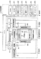
以下、本発明の実施形態を図面を用いて説明する。図1は第1の実施形態の信号処理の手順を示す図、図2は磁気共鳴撮像装置の全体構成を示すブロック図、図3は第1の実施形態の本計測の撮像シーケンスを示す図、図4は第1の実施形態のリファレンス計測の撮像シーケンスを示す図である。
【0012】
図2に示すように、磁気共鳴撮像装置は、静磁場発生回路1、傾斜磁場発生系2、送信系3、受信系4、信号処理系5、シーケンサ6、及び中央処理装置(CPU)7、操作部8を備えて構成される。静磁場発生回路1は、被検体9が置かれる空間に均一な静磁場を発生させるものである。その静磁場の方向は、通常、被検体9の体軸方向又は体軸に直交する方向である。また、静磁場発生回路1は、永久磁石方式または常電導方式あるいは超電導方式を用いて形成されている。傾斜磁場発生系2は、直交3軸(X、Y、Z)方向の傾斜磁場を発生する傾斜磁場コイル10と、その傾斜磁場コイル10の駆動電流を供給する傾斜磁場電源11を有して構成されている。傾斜磁場電源11は、シーケンサ6の命令に従って直交3軸(X,Y,Z)方向の傾斜磁場Gs、Gp、Grを被検体9に印加するようになっている。この傾斜磁場の与え方によって断層像のスライス面を設定することができる。シーケンサ6はCPU7の制御により動作し、パルスシーケンスと称される撮像シーケンスに従って、傾斜磁場発生系2、送信系3、受信系4等に命令を送り、断層像を撮像するのに必要な制御を実行するものである。
【0013】
送信系3は、高周波磁場パルスにより被検体9の生体組織を構成する原子核に核磁気共鳴を起こさせるために高周波磁場パルスを照射するもので、高周波発振器12、変調器13、高周波増幅器14及び高周波照射コイル15を有して構成されている。そして、送信系3は、シーケンサ6の命令に従って、高周波発振器12から出力される高周波磁場パルスを変調器13で振幅変調し、さらに高周波増幅器14で増幅した後、高周波照射コイル15に供給して高周波磁場パルス(RFパルス)を被検体9に照射するようになっている。
【0014】
受信系4は、被検体9の生体組織の原子核の核磁気共鳴により放出されるエコー信号などの磁気共鳴信号を検出するもので、受信側の高周波受信コイル16、増幅器17、直交位相検波器18及びA/D変換器19を有して構成される。高周波受信コイル16により受波された磁気共鳴信号は増幅器17で増幅され、直交位相検波器18で検波された後、A/D変換器19でディジタル信号の計測データに変換される。なお、シーケンサ6の制御によるタイミングで直交位相検波器18により位相を90°ずらしてサンプリングされた二系列の計測データは、信号処理系5に送られる。
【0015】
信号処理系5は、CPU7、ROM20、RAM21、光磁気ディスク22、CRTなどのディスプレイ23及び磁気ディスク24を有して構成される。CPU7は、入力される計測データをフーリエ変換処理、補正係数計算を含む画像再構成処理を行い、任意断面の信号強度分布あるいは所定の処理をした画像を作成して、ディスプレイ23に断層像として表示するようになっている。ROM20は、経時的な画像解析処理及び計測を行なうプログラムや、その実行に用いる不変のパラメータなどを記憶する。RAM21は、前計測で用いた計測パラメータや、受信系4で検出したエコー信号、及び関心領域設定に用いる画像を一時保管すると共に、その関心領域を設定するためのパラメータなどを記憶する。光磁気ディスク22及び磁気ディスク24は、CPU7により再構成された画像のデータを記録する。ディスプレイ23は、光磁気ディスク22及び磁気ディスク24に格納されている画像データを映像化して断層像として表示する。
【0016】
操作部8は、信号処理系で実行する処理の制御情報を入力するものであり、例えば、トラックボール又はマウス25やキーボード26を備えて構成される。
【0017】
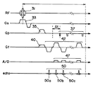
このように構成される磁気共鳴撮像装置を用いて撮像して得たデータの処理及び画像再構成について図1を参照して説明する。ステップ1では、図3で示すパルスシーケンスと称される撮像シーケンスを実行し、本計測エコー信号を得る。ステップ6においても、図4で示す撮像シーケンスを実行し、リファレンス計測エコー信号を得る。図3と図4の撮像シーケンスは、エコープラナーイメージング(EPI)法と呼ばれるパルスシーケンスを用いている。図3及び図4とも、上から順に高周波磁場パルスRF,スライス選択傾斜磁場Gs,位相エンコード傾斜磁場Gp,読み出し方向(リードアウト)傾斜磁場Gf、サンプリングウインドAD、磁気共鳴信号であるエコー信号echoをそれぞれ示し、縦軸はそれらの強度を、横軸は時間を示している。このパルスシーケンスを1回または複数回繰り返すことにより、画像再構成に必要な計測データがk空間に収集される。
【0018】
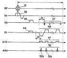
次に、図3と図4のシーケンスの内容を詳細に説明する。図3では、高周波磁場パルス31を照射すると共に、スライス選択傾斜磁場パルス33を印加することにより、被検体の所望の部位を励起する。これにより被検体中の例えばプロトンが励起され、位相エンコードのオフセットを与えるGpパルス35と読み出し方向のオフセットを与えるGfパルス39を印加し、そして、極性を反転させたGfパルス41aを印加することによりエコー信号49aが得られる。その後、Gpパルス37を離散的に印加しながら極性の反転を繰り返すGfパルス41b、41cと引き続き印加して、第2、第3とさらに続くエコー信号49b、49c等が得られる。Gpパルスを離散的に印加するとは、位相エンコード量を変えてエコー信号を取得することで、k空間の位相エンコード数に対応した画像情報を得るためである。また、Gfパルスの極性を反転しながら繰り返し印加するのは、1回の高周波磁場パルス31で、複数のエコー(グラジエントエコー)信号を得るためである。図3と図4のパルスシーケンスの違いは、Gfパルスの極性が相互で異なることで、すなわち、同一位相エンコード量のときに、図3のGfパルスと図4のGfパルスは、極性が反対となっている点である。例えば、図3のGfパルス39と図4のGfパルス43、図3のGfパルス41aと図4のGfパルス45a、図3のGfパルス41bと図4のGfパルス45bは、相互に極性が逆になっている。その他の点は、図3及び図4とも同じである。
【0019】
図1のステップ1の本計測エコー信号h(n,m,t)とステップ6のリファレンス計測エコー信号r(n,m,t)を、それぞれ読み出し方向にフーリエ変換して、本計測データh(n,m,x)とリファレンス計測データr(n,m,x)を得る(S2,S7)。ここで、mはエコー番号、tは時間、nはパルスシーケンスの繰り返し番号、xは読み出し方向の位置である。次に、上記の本計測データh(n,m,x)とリファレンス計測データr(n,m,x)に含まれる実画像中における読み出し方向の位相傾斜となるような位相誤差成分を補正し(S4、S9)、位相補正後の本計測データh’(n,m,x)とリファレンス計測データr’(n,m,x)を得る(S5、S10)。この補正(S4、S9)は、従来技術の補正で、本実施形態だけでは補正することが困難である静磁場の不均一等による位相誤差の補正のために同一の位相補正量を与えるものである。
【0020】
この従来技術の補正方法は、例えば本計測に先だって、位相エンコード傾斜磁場を加えない状態で補正用のデータを取得しておき、この補正用データ及び本計測データをそれぞれ読み出し方向に1次元フーリエ変換し、本計測データから補正用データの位相を減算する方法(特開平5-68674)や、読み出し方向傾斜磁場の極性が異なる2回の計測により得られたそれぞれのデータのうち、偶数エコーのみを使用して作成した2枚の画像の位相差を、本計測データの偶数エコーのみを使用して作成した画像の位相に適用することにより、本計測データの偶数エコーと奇数エコーの位相差を補正する方法(“Single-Shot and Segmented EPI Ghost Artifacts Removal with Two-Dimensional Phase Correct”
;Nan-kuei Chen, Alice M.Wyrwicz; Proceedings of International Society for Magnetic Resonance in Medicin,8,1713(2000))などがある。
【0021】
次に、ステップ11において、位相補正後の本計測データh’(n,m,x)とリファレンス計測データr’(n,m,x)を下記に示す式(1)と(2)により複素加算を行う。
【0022】
re[S(n,m,x)]=re[h’(n,m,x)]+re[r’(n,m,x)] (1)
im[S(n,m,x)]=im[h’(n,m,x)]+im[r’(n,m,x)] (2)
各エコー信号のサンプリング中に生じるエコー信号のサンプリング中に線形もしくは非線形の位相誤差があっても、同一の位相エンコード量で読み取り傾斜磁場パルスの極性を逆にして得た本計測データとリファレンス計測データを複素加算することで、位相誤差は打ち消し合うことができる。そして、複素加算で算出されたデータS(n,m,x)をステップ13により位相エンコード方向にフーリエ変換し、ステップ14でN/2アーチファクトのない画像I(x,y)を作成することができる。ここで、yは位相エンコード方向の位置である。なお、上記複素加算は、位相補正後の本計測データh’(n,m,x)とリファレンス計測データr’(n,m,x)をそれぞれ位相エンコード方向にフーリエ変換した後に実行してもよい。また、位相補正(S4、S9)を省略して、読み出し方向フーリエ変換(S2、S7)後の本計測データh(n,m,x)とリファレンス計測データr(n,m,x)を複素加算してもよい。位相補正(S4、S9)は、本実施形態だけでは補正することが困難である静磁場の不均一等による位相誤差の補正に関するもので、この位相補正をすることで、画像がより鮮明になる。
【0023】
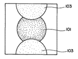
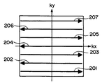
図8は、N/2アーチファクトの出現を示した図で、画像領域101に、アーチファクト領域103が出現している状態を示している。図9は、EPIパルスシーケンスで計測されるエコー信号のk空間における収集軌跡を示した図である。読み出し方向傾斜磁場の極性が交互に反転するため、奇数エコー信号201、203、205、207と偶数エコー信号202、204、206とでは、エコー信号収集軌跡が逆になる。そして、傾斜磁場の極性を高速に反転させることによる渦電流や磁場の不完全性等により、偶数エコー信号202、204、206と奇数エコー信号201、203、205、207とで位相差が生じ、画像再構成するとN/2アーチファクトが現れる。この偶数エコー信号と奇数エコー信号の位相差を、上記ステップ11の複素加算により打ち消してN/2アーチファクトの出現を抑えた画像再構成、表示を行うことができる。
【0024】
次に、本発明の第2の実施形態である連続撮像における計測(以下「ダイナミック計測」という)のデータ処理について図5を用いて説明する。図5は、ダイナミック計測における信号処理の手順の概略を示す図である。Scan A61、 Scan B63、Scan A65及びScan B67は、それぞれ1枚の画像再構成のパルスシーケンスを実行するもので、読み出し方向傾斜磁場の極性の順序を交互に変えているものである。Scan A61の計測データ69を位相補正77したデータとScan B63の計測データ71を位相補正したデータ79とを複素加算し、画像I1(x,y)91を得る。次に、Scan B63の計測データを位相補正したデータ79とScan A65の計測データを位相補正したデータ81を複素加算して画像I2(x,y)93を得る。同様にして、位相補正したデータ81と83を複素加算して画像I3(x,y)95を得る。各Scanは、交互に読み出し方向傾斜磁場の極性の順序をかえているので、隣あうScanで得られた計測データは、同一位相エンコード量のときは読み出し方向傾斜磁場の極性が逆になるので、エコー信号のサンプリング中に線形もしくは非線形の位相誤差があっても、複素加算することで、位相誤差は打ち消し合うことができる。その結果、画像画像I1(x,y)91、画像I2(x,y)93及び画像I3(x,y)95は、N/2アーチファクトの出現を抑えることができる。図5は、図1と同様に読み出し方向フーリエ変換、位相エンコードフーリエ変換をおこなうものであるが、図中では記載を省略している。また、位相補正77、79、81、83については、第1の実施形態と同様に省略してもよい。
【0025】
次に、本発明の第3の実施形態を図6及び図7を用いて説明する。図6及び図7は、パルスシーケンス図で、第1の実施形態と相違する点はいずれも読み出し方向のオフセットを与えるGfパルス40、44の極性が同一であることである。これによって、同一の位相エンコード量であってGfパルスの極性が逆である2種類のエコー信号を計測するために、図6のシーケンスでは位相エンコード傾斜磁場パルス37の印加タイミングをエコー間隔Δtだけ時間をずらし、Gfパルス42は通常通り極性を反転して繰り返し印可する。この時、図6の第1のエコー信号50aは計測しない。図7では、図6と位相エンコード量が同一でかつGfパルスの極性が逆になるようにΔtの時間経過後にGfパルス48を印加する。そして、図6のエコー信号50bと図7のエコー信号52b、図6のエコー信号50cと図7のエコー信号52c等により得られたデータをそれぞれ複素加算して、位相誤差を打ち消し画像再構成する。この場合も、複素加算の前に、位相補正を行うことが望ましい。静磁場不均一等による位相誤差が補正され、より鮮明な画像がえられるからである。
【0026】
【発明の効果】
本発明によれば、各エコー信号ごとに異なる位相誤差が生じている場合でもアーチファクトの発生を抑えることができる。
【図面の簡単な説明】
【図1】本発明に係る第1の実施形態の信号処理の手順を示す図である。
【図2】本発明に係る一実施形態の磁気共鳴撮像装置の全体構成を示すブロック図である。
【図3】本発明に係る第1の実施形態の本計測撮像シーケンスを示す図である。
【図4】本発明に係る第1の実施形態のリファレンス測撮像シーケンスを示す図である。
【図5】本発明に係る第2の実施形態の信号処理の手順を示す図である。
【図6】本発明に係る第3の実施形態の撮像シーケンスの第1例を示す図である。
【図7】本発明に係る第3の実施形態の撮像シーケンスの第2例を示す図である。
【図8】N/2アーチファクトの出現を示した図である。
【図9】EPIパルスシーケンスで計測されるエコー信号のk空間における収集軌跡を示した図である。
【符号の説明】
1 静磁場発生回路
2 傾斜磁場発生系
3 送信系
4 受信系
5 信号処理系
6 シーケンサ
7 CPU
8 操作部
9 被検体
10 傾斜磁場回路
15 高周波照射コイル
31 高周波磁場パルス
33 スライス傾斜磁場パルス
35 位相エンコードオフセットパルス
37 位相エンコード傾斜磁場パルス
39、40、43 読み出し方向オフセットパルス
41、42 読み出し方向傾斜磁場パルス
49、50、51、52 エコー信号[0001]
BACKGROUND OF THE INVENTION
The present invention relates to a magnetic resonance imaging apparatus, and more particularly to a technique for suppressing the appearance of artifacts caused by a phase change between echo signals.
[0002]
[Prior art]
A magnetic resonance imaging apparatus (MRI apparatus) irradiates a living body with a high-frequency magnetic field pulse in a state where a uniform static magnetic field acts on the living body, excites nuclei such as hydrogen and phosphorus in the living body, and generates nuclear magnetic resonance generated by this excitation. It is an apparatus that contributes to medical diagnosis by measuring a signal (NMR signal) and imaging a measurement region in a living body based on magnetic resonance information such as the density distribution or relaxation time distribution of hydrogen and phosphorus.
[0003]
In the MRI apparatus, there are many methods for measuring an echo signal (NMR signal) as typified by a spin echo method and a gradient echo method. Among them, there is an ultra-high-speed imaging method that measures a plurality of echo signals by repeatedly inverting a readout gradient magnetic field that is a readout direction after irradiation with a high-frequency magnetic field pulse. For example, there are a single shot EPI (Echo Planar Imaging) method, a multi-shot EPI method, a gradient and spin echo imaging (Gradient and Spin Echo Imaging) method, and the like. In such an imaging method, in addition to the inhomogeneity of the static magnetic field, eddy currents caused by high-speed reversal of the polarity of the magnetic field in the readout direction, imperfections in the magnetic field in the readout direction, etc. An error occurs. Among the measured echo signals, the polarity of the gradient magnetic field in the readout direction alternates between the odd-numbered echo signal (hereinafter referred to as “odd echo”) and the even-numbered echo signal (hereinafter referred to as “even echo”). Since it is inverted, the echo signal collection trajectory in the so-called k space which is the measurement space is reversed, and the polarity of the phase error is also inverted in the readout direction.
[0004]
When a phase difference occurs between the even echo and the odd echo in this way, an artifact called N / 2 ghost (hereinafter referred to as “N / 2 artifact”) occurs in the image that has undergone image reconstruction. A method has been proposed in which N / 2 artifacts are removed by signal processing by utilizing the fact that the phase error contained in each echo signal is mainly a phase gradient in the readout direction on an actual image. In this method, correction data is acquired in advance, and the echo signal in the main measurement for image formation is corrected using the correction data.
[0005]
As this correction means, for example, a method of acquiring a set of even and odd echoes as correction data, Fourier transforming these echo signals, obtaining a phase difference between the echo signals, and correcting this measurement data is disclosed in JP It is disclosed in Japanese Patent Laid-Open No. 8-215174. Prior to the main measurement, correction data is acquired without applying the phase encode gradient magnetic field, and the correction data and the main measurement data are each subjected to a one-dimensional Fourier transform in the reading direction, and corrected from the main measurement data. The method of subtracting the phase of the data for use is described in Japanese Patent Laid-Open No. 5-68674, etc. Further, even echoes and odd echoes are obtained by data obtained by two measurements obtained by inverting the polarity of the gradient magnetic field in the readout direction. There is a method to calculate the phase difference and correct the phase error between even and odd echoes in this measurement data (“Single-Shot and Segmented EPI Ghost Artifacts Removal with Two-Dimensional Phase Correct”; Nan-kuei Chen, Alice M . Wyrwicz; Proceeding of International Society for Magnetic Resonance in Medicin, 8, 1713 (2000)).
[0006]
[Problems to be solved by the invention]
Correcting the phase gradient in the readout direction on the actual image as in the conventional correction method described above gives the same phase correction amount to all pixels in the readout direction on the k space. For this reason, when a linear or non-linear phase error occurs during sampling of each echo signal due to eddy current or imperfection of the gradient magnetic field in the readout direction, it cannot be eliminated with the same correction amount, and N / 2 Artifacts occur, and the generation of artifacts cannot be suppressed in image reconstruction.
[0007]
An object of the present invention is to suppress the occurrence of artifacts even when a linear or non-linear phase error occurs during sampling of each echo signal.
[0008]
[Means for Solving the Problems]
In order to solve the above-described problems, a magnetic resonance imaging apparatus of the present invention includes a static magnetic field generation unit that applies a static magnetic field to a subject , a gradient magnetic field generation unit that applies a gradient magnetic field, and a high-frequency magnetic field that irradiates the subject with electromagnetic waves. and pulse irradiation means, and said sequencer for executing a receiving means for receiving a magnetic resonance signal generated from the subject, the gradient magnetic field generating means and the high-frequency magnetic field pulse irradiation means and imaging sequence to control said receiving means, Magnetic resonance imaging comprising signal processing means for reconstructing an image based on the magnetic resonance signal, and display means for displaying the image, and changing the phase encoding at the time of measurement and measuring the readout gradient magnetic field pulse by inverting the polarity in the apparatus, the sequencer has first and second imaging sequence, the first imaging sequence, the first readout gradient pulse positive Is inverted, the second imaging sequence to form a second readout gradient pulse obtained by inverting the polarity of the first readout gradient pulse,
In the first imaging sequence and the second imaging sequence, the phase encoding pulse is discretely applied in accordance with the positive / negative inversion of the first readout gradient magnetic field pulse and the second readout gradient magnetic field pulse, and the phase encoding is performed. And the polarities of the first readout gradient magnetic field pulse and the second readout gradient magnetic field pulse in the same phase encoding amount are reversed to each other, and the signal processing means obtains the first imaging sequence obtained by the first imaging sequence. One measurement data and the second measurement data obtained by the second imaging sequence are added to reconstruct an image.
[0009]
With such a configuration, even when the phase error of the linear or non-linear during the sampling occurs in each echo signal (measurement data), an echo signal with each other to reverse the polarity of the magnetic field gradient out read pressurized Therefore, the occurrence of N / 2 artifacts can be suppressed by canceling out the mutual phase error, so that the phase error generated in each echo signal can be eliminated and the occurrence of artifacts can be suppressed.
[0010]
The first sequence and the second sequence are alternately executed repeatedly, and the signal processing means performs complex addition of echo signals having the same phase encoding amount obtained by the first sequence and the second sequence. It is preferable to reconstruct images continuously. When continuously reconstructing an image, even if a linear or non-linear phase error occurs in each echo signal during sampling, it is possible to cancel the mutual phase error and suppress the occurrence of N / 2 artifacts. Therefore, it is possible to eliminate the linear or non-linear phase error during sampling of each echo signal and suppress the occurrence of artifacts.
The first and second sequences differ only in the polarity order of the gradient magnetic field in the readout direction, so that the echo times are the same and complex addition can be performed easily.
[0011]
DETAILED DESCRIPTION OF THE INVENTION
Hereinafter, embodiments of the present invention will be described with reference to the drawings. FIG. 1 is a diagram illustrating a signal processing procedure according to the first embodiment, FIG. 2 is a block diagram illustrating an overall configuration of the magnetic resonance imaging apparatus, and FIG. 3 is a diagram illustrating an imaging sequence of the main measurement according to the first embodiment. FIG. 4 is a diagram illustrating an imaging sequence for reference measurement according to the first embodiment.
[0012]
As shown in FIG. 2, the magnetic resonance imaging apparatus includes a static magnetic
[0013]
The
[0014]
The receiving system 4 detects a magnetic resonance signal such as an echo signal emitted by nuclear magnetic resonance of the nucleus of the biological tissue of the
[0015]
The signal processing system 5 includes a
[0016]
The operation unit 8 inputs control information for processing executed in the signal processing system, and includes, for example, a trackball or a
[0017]
Processing of data obtained by imaging using the magnetic resonance imaging apparatus configured as described above and image reconstruction will be described with reference to FIG. In
[0018]
Next, the contents of the sequences in FIGS. 3 and 4 will be described in detail. In FIG. 3, while irradiating the high frequency
[0019]
The main measurement echo signal h (n, m, t) in
[0020]
In this prior art correction method, for example, prior to the main measurement, correction data is acquired without applying a phase encoding gradient magnetic field, and the correction data and the main measurement data are each subjected to a one-dimensional Fourier transform in the reading direction. However, only the even echoes of the data obtained by subtracting the phase of the correction data from this measurement data (Japanese Patent Laid-Open No. 5-68674) and the two measurements obtained with two different polarities of the gradient magnetic field in the readout direction are used. Correct the phase difference between the even and odd echoes in the actual measurement data by applying the phase difference between the two images created using the image to the phase of the image created using only the even echoes in the actual measurement data. (“Single-Shot and Segmented EPI Ghost Artifacts Removal with Two-Dimensional Phase Correct”
Nan-kuei Chen, Alice M. Wyrwicz; Proceedings of International Society for Magnetic Resonance in Medicin, 8, 1713 (2000)).
[0021]
Next, in
[0022]
re [S (n, m, x)] = re [h '(n, m, x)] + re [r' (n, m, x)] (1)
im [S (n, m, x)] = im [h '(n, m, x)] + im [r' (n, m, x)] (2)
This measurement data and reference measurement data obtained by reversing the polarity of the read gradient magnetic field pulse with the same phase encoding amount even if there is a linear or nonlinear phase error during the sampling of the echo signal that occurs during the sampling of each echo signal The phase error can be canceled out by complex addition. Then, the data S (n, m, x) calculated by the complex addition is Fourier-transformed in the phase encoding direction at
[0023]
FIG. 8 is a diagram showing the appearance of N / 2 artifacts, and shows a state where the
[0024]
Next, data processing of measurement (hereinafter referred to as “dynamic measurement”) in continuous imaging according to the second embodiment of the present invention will be described with reference to FIG. FIG. 5 is a diagram showing an outline of a signal processing procedure in dynamic measurement. Scan A61, Scan B63, Scan A65, and Scan B67 each execute one image reconstruction pulse sequence, and alternately change the order of the polarities of the read direction gradient magnetic fields. Data obtained by
[0025]
Next, a third embodiment of the present invention will be described with reference to FIGS. FIGS. 6 and 7 are pulse sequence diagrams. The difference from the first embodiment is that the polarities of the
[0026]
【The invention's effect】
According to the present invention, the occurrence of artifacts can be suppressed even when different phase errors occur for each echo signal.
[Brief description of the drawings]
FIG. 1 is a diagram showing a procedure of signal processing according to a first embodiment of the present invention.
FIG. 2 is a block diagram showing an overall configuration of a magnetic resonance imaging apparatus according to an embodiment of the present invention.
FIG. 3 is a diagram illustrating a main measurement imaging sequence according to the first embodiment of the present invention.
FIG. 4 is a diagram showing a reference measurement imaging sequence according to the first embodiment of the present invention.
FIG. 5 is a diagram showing a procedure of signal processing according to the second embodiment of the present invention.
FIG. 6 is a diagram illustrating a first example of an imaging sequence according to a third embodiment of the present invention.
FIG. 7 is a diagram illustrating a second example of an imaging sequence according to the third embodiment of the present invention.
FIG. 8 shows the appearance of N / 2 artifacts.
FIG. 9 is a diagram showing an acquisition trajectory in the k space of echo signals measured by an EPI pulse sequence.
[Explanation of symbols]
DESCRIPTION OF
8
Claims (6)
前記シーケンサは第1及び第2の撮像シーケンスを有し、
前記第1の撮像シーケンスは、第1の読み出し傾斜磁場パルスを正負反転させ、
前記第2の撮像シーケンスは、前記第1の読み出し傾斜磁場パルスの極性を反転させた第2の読み出し傾斜磁場パルスを形成させ、
前記第1の撮像シーケンス及び第2の撮像シーケンスは、前記第1の読み出し傾斜磁場パルス及び前記第2の読み出し傾斜磁場パルスの正負反転に合わせて位相エンコードパルスを離散的に印加して前記位相エンコードを変化させ、かつ、同一位相エンコード量における前記第1の読み出し傾斜磁場パルスと前記第2の読み出し傾斜磁場パルスの極性を互いに逆にし、
前記信号処理手段は、第1の撮像シーケンスにより得られる第1の計測データと、前記第2の撮像シーケンスにより得られる第2の計測データとを加算して画像再構成することを特徴とする磁気共鳴撮像装置。 Receiving a static magnetic field generating means for applying a static magnetic field to the subject, a gradient magnetic field generating means for applying a gradient magnetic field, a high-frequency magnetic field pulse applying means for applying an electromagnetic wave to the subject, the magnetic resonance signal generated from the subject A receiving unit, a sequencer that controls the gradient magnetic field generating unit, the high-frequency magnetic field pulse irradiating unit, and the receiving unit to execute an imaging sequence; a signal processing unit that reconstructs an image based on the magnetic resonance signal ; A magnetic resonance imaging apparatus comprising: a display unit configured to display the image; changing a phase encoding at the time of measurement ;
The sequencer has first and second imaging sequences,
In the first imaging sequence, the first readout gradient magnetic field pulse is inverted between positive and negative,
The second imaging sequence forms a second readout gradient magnetic field pulse in which the polarity of the first readout gradient magnetic field pulse is reversed,
In the first imaging sequence and the second imaging sequence, the phase encoding pulse is discretely applied in accordance with the positive / negative inversion of the first readout gradient magnetic field pulse and the second readout gradient magnetic field pulse, and the phase encoding is performed. And the polarities of the first readout gradient magnetic field pulse and the second readout gradient magnetic field pulse in the same phase encoding amount are reversed to each other,
The signal processing means adds the first measurement data obtained by the first imaging sequence and the second measurement data obtained by the second imaging sequence to reconstruct an image. Resonance imaging device.
前記信号処理手段は連続的に画像再構成することを特徴とする請求項1に記載の磁気共鳴撮像装置。 The magnetic resonance imaging apparatus according to claim 1, wherein the signal processing unit continuously reconstructs an image.
Priority Applications (4)
| Application Number | Priority Date | Filing Date | Title |
|---|---|---|---|
| JP2001317262A JP4122452B2 (en) | 2001-10-15 | 2001-10-15 | Magnetic resonance imaging device |
| US10/492,640 US7418286B2 (en) | 2001-10-15 | 2002-10-15 | Magnetic resonance imaging apparatus and magnetic resonance imaging method |
| CNB028204638A CN100415161C (en) | 2001-10-15 | 2002-10-15 | Magnetic resonance imaging device and magnetic resonance imaging method |
| PCT/JP2002/010662 WO2003032830A1 (en) | 2001-10-15 | 2002-10-15 | Magnetic resonance imaging apparatus and magnetic resonance imaging method |
Applications Claiming Priority (1)
| Application Number | Priority Date | Filing Date | Title |
|---|---|---|---|
| JP2001317262A JP4122452B2 (en) | 2001-10-15 | 2001-10-15 | Magnetic resonance imaging device |
Publications (3)
| Publication Number | Publication Date |
|---|---|
| JP2003116815A JP2003116815A (en) | 2003-04-22 |
| JP2003116815A5 JP2003116815A5 (en) | 2005-06-30 |
| JP4122452B2 true JP4122452B2 (en) | 2008-07-23 |
Family
ID=19135164
Family Applications (1)
| Application Number | Title | Priority Date | Filing Date |
|---|---|---|---|
| JP2001317262A Expired - Lifetime JP4122452B2 (en) | 2001-10-15 | 2001-10-15 | Magnetic resonance imaging device |
Country Status (4)
| Country | Link |
|---|---|
| US (1) | US7418286B2 (en) |
| JP (1) | JP4122452B2 (en) |
| CN (1) | CN100415161C (en) |
| WO (1) | WO2003032830A1 (en) |
Families Citing this family (24)
| Publication number | Priority date | Publication date | Assignee | Title |
|---|---|---|---|---|
| JP4619674B2 (en) * | 2004-03-24 | 2011-01-26 | 株式会社東芝 | Magnetic resonance imaging system |
| JP4625677B2 (en) * | 2004-10-25 | 2011-02-02 | 株式会社東芝 | Magnetic resonance imaging apparatus and image correction evaluation method |
| WO2006118110A1 (en) * | 2005-04-26 | 2006-11-09 | Hitachi Medical Corporation | Magnetic resonance imaging device and method |
| CN100589756C (en) * | 2005-04-28 | 2010-02-17 | 株式会社日立医药 | Magnetic resonance imaging apparatus |
| US7375519B2 (en) * | 2006-04-20 | 2008-05-20 | General Electric Company | Method and apparatus of MR imaging with two dimensional phase and magnitude correction |
| JP5366484B2 (en) * | 2007-09-28 | 2013-12-11 | 株式会社東芝 | Magnetic resonance imaging apparatus and analysis method of fat suppression effect in the magnetic resonance imaging apparatus |
| US8008915B2 (en) * | 2007-12-28 | 2011-08-30 | Kabushiki Kaisha Toshiba | Magnetic resonance imaging apparatus and magnetic resonance imaging method |
| US9341691B2 (en) * | 2008-11-12 | 2016-05-17 | Regents Of The University Of Minnesota | Short TE 3D radial sampling sequence for MRI |
| JP5275007B2 (en) * | 2008-12-16 | 2013-08-28 | ジーイー・メディカル・システムズ・グローバル・テクノロジー・カンパニー・エルエルシー | Magnetic resonance imaging system |
| WO2011106649A1 (en) * | 2010-02-25 | 2011-09-01 | Mcw Research Foundation, Inc. | Method for simultaneous multi-slice magnetic resonance imaging using single and multiple channel receiver coils |
| US9256977B2 (en) * | 2012-02-01 | 2016-02-09 | Siemens Medical Solutions Usa, Inc. | System for reconstruction of virtual frequency selective inversion MR images |
| DE102013209295B4 (en) * | 2013-05-21 | 2016-11-17 | Siemens Healthcare Gmbh | Correction of MR image datasets using a similarity of temporally successive datasets |
| DE102014211034A1 (en) * | 2014-06-10 | 2015-12-17 | Siemens Aktiengesellschaft | Medical imaging device and method for a medical imaging device |
| US9971008B2 (en) * | 2014-09-30 | 2018-05-15 | Toshiba Medical Systems Corporation | MRI gradient trajectory mapping |
| JPWO2016067860A1 (en) * | 2014-10-30 | 2017-08-10 | 株式会社日立製作所 | Magnetic resonance imaging apparatus and magnetic resonance imaging method |
| JP2016198392A (en) * | 2015-04-13 | 2016-12-01 | 東芝メディカルシステムズ株式会社 | Magnetic resonance imaging system |
| JP7539255B2 (en) * | 2020-05-21 | 2024-08-23 | 富士フイルムヘルスケア株式会社 | Magnetic Resonance Imaging |
| JP7609622B2 (en) * | 2020-12-14 | 2025-01-07 | 富士フイルム株式会社 | Magnetic resonance imaging apparatus and control method thereof |
| JP7557741B2 (en) | 2021-02-25 | 2024-09-30 | 富士フイルム株式会社 | Magnetic resonance imaging apparatus, image correction method, and static magnetic field inhomogeneity correction method |
| CN115113122B (en) * | 2021-03-18 | 2025-09-12 | 佳能医疗系统株式会社 | Image processing device and image processing method |
| JP7722899B2 (en) * | 2021-10-22 | 2025-08-13 | キヤノンメディカルシステムズ株式会社 | Magnetic resonance imaging device and magnetic resonance imaging program |
| EP4261557A1 (en) * | 2022-04-15 | 2023-10-18 | Koninklijke Philips N.V. | Mr imaging using partial echo acquisition |
| CN115685032B (en) * | 2022-11-02 | 2023-06-23 | 佛山瑞加图医疗科技有限公司 | Correction method and system for fast spin echo under spoke k-space |
| DE102024200167B3 (en) * | 2024-01-09 | 2025-04-30 | Siemens Healthineers Ag | Method for operating a magnetic resonance device, magnetic resonance device, computer program and electronically readable data carrier |
Family Cites Families (13)
| Publication number | Priority date | Publication date | Assignee | Title |
|---|---|---|---|---|
| JPH0811112B2 (en) * | 1985-03-11 | 1996-02-07 | 株式会社日立製作所 | Inspection equipment using nuclear magnetic resonance |
| US4780675A (en) * | 1987-08-14 | 1988-10-25 | Picker International, Inc. | Conjugate symmetry magnetic resonance imaging |
| EP0644437B1 (en) * | 1993-09-16 | 1999-05-12 | Koninklijke Philips Electronics N.V. | Correction of read-gradient polarity in EPI and GRASE MRI |
| JP3544782B2 (en) * | 1996-04-16 | 2004-07-21 | 株式会社東芝 | Magnetic resonance diagnostic equipment |
| US5742163A (en) * | 1996-04-26 | 1998-04-21 | Picker International, Inc. | Magnetic resonance scan calibration and reconstruction technique for multi-shot, multi-echo imaging |
| JPH11512957A (en) * | 1996-07-08 | 1999-11-09 | コーニンクレッカ フィリップス エレクトロニクス エヌ ヴィ | Method and apparatus for magnetic resonance imaging |
| US6249595B1 (en) * | 1998-01-22 | 2001-06-19 | General Electric Company | Iterative reconstruction for EPI |
| JP4127889B2 (en) * | 1998-03-04 | 2008-07-30 | 株式会社日立メディコ | Magnetic resonance imaging system |
| JP3519270B2 (en) * | 1998-04-08 | 2004-04-12 | 独立行政法人理化学研究所 | Magnetic resonance imaging apparatus and signal processing method in magnetic resonance imaging apparatus |
| US6259250B1 (en) * | 1999-04-28 | 2001-07-10 | General Electric Company | Method and apparatus for reducing artifacts in echo planar imaging |
| US6285187B1 (en) * | 1999-04-28 | 2001-09-04 | General Electric Company | Method and apparatus for reducing artifacts in echo planar imaging |
| US6424914B1 (en) * | 2000-12-26 | 2002-07-23 | American Gnc Corporation | Fully-coupled vehicle positioning method and system thereof |
| US6841998B1 (en) * | 2001-04-06 | 2005-01-11 | Mark Griswold | Magnetic resonance imaging method and apparatus employing partial parallel acquisition, wherein each coil produces a complete k-space datasheet |
-
2001
- 2001-10-15 JP JP2001317262A patent/JP4122452B2/en not_active Expired - Lifetime
-
2002
- 2002-10-15 WO PCT/JP2002/010662 patent/WO2003032830A1/en not_active Ceased
- 2002-10-15 US US10/492,640 patent/US7418286B2/en not_active Expired - Lifetime
- 2002-10-15 CN CNB028204638A patent/CN100415161C/en not_active Expired - Lifetime
Also Published As
| Publication number | Publication date |
|---|---|
| CN1571647A (en) | 2005-01-26 |
| JP2003116815A (en) | 2003-04-22 |
| WO2003032830A1 (en) | 2003-04-24 |
| US20040245986A1 (en) | 2004-12-09 |
| CN100415161C (en) | 2008-09-03 |
| US7418286B2 (en) | 2008-08-26 |
Similar Documents
| Publication | Publication Date | Title |
|---|---|---|
| JP4122452B2 (en) | Magnetic resonance imaging device | |
| JP5399240B2 (en) | Magnetic resonance imaging apparatus and method for correcting error caused by gradient magnetic field | |
| US9341694B2 (en) | Method and magnetic resonance system for distortion correction in magnetic resonance imaging | |
| US7015696B2 (en) | Magnetic resonance imaging apparatus and magnetic resonance imaging method | |
| US8587306B2 (en) | Magnetic resonance imaging apparatus and multi-contrast acquiring method | |
| US8587310B2 (en) | Magnetic resonance imaging device | |
| EP1472978B1 (en) | Magnetic resonance imaging method and apparatus | |
| CN103260510B (en) | Magnetic resonance imaging device and contrast-enhanced image acquisition method | |
| US9476956B2 (en) | Magnetic resonance imaging apparatus with correction of magnetic field gradient waveform distortion | |
| JP2007117765A (en) | Measurement and correction of gradient-induced cross-term magnetic fields in epi sequence | |
| JP2000157507A (en) | Nuclear magnetic resonance imaging system | |
| CN102238909B (en) | Magnetic resonance imaging device and synchronous imaging method | |
| JP4330247B2 (en) | Nuclear magnetic resonance imaging system | |
| JP4390328B2 (en) | Magnetic resonance imaging system | |
| JP2004089275A (en) | Phase correction method in magnetic resonance imaging device | |
| JP5650044B2 (en) | Magnetic resonance imaging system | |
| JP2002085376A (en) | Nuclear magnetic resonance imaging device and method | |
| CN114624639B (en) | Magnetic resonance imaging device and control method thereof | |
| JP6718764B2 (en) | Magnetic resonance imaging apparatus and control method thereof | |
| JP4912802B2 (en) | Magnetic resonance imaging apparatus, transmission sensitivity distribution measuring apparatus, and transmission sensitivity distribution measuring method | |
| JP4397137B2 (en) | Magnetic resonance imaging device | |
| JP2006061235A (en) | Magnetic resonance imaging device | |
| JP3688795B2 (en) | Magnetic resonance imaging system | |
| JP5004588B2 (en) | Magnetic resonance imaging system | |
| JP3612656B2 (en) | Magnetic resonance imaging system |
Legal Events
| Date | Code | Title | Description |
|---|---|---|---|
| A521 | Request for written amendment filed |
Free format text: JAPANESE INTERMEDIATE CODE: A523 Effective date: 20041013 |
|
| A621 | Written request for application examination |
Free format text: JAPANESE INTERMEDIATE CODE: A621 Effective date: 20041013 |
|
| TRDD | Decision of grant or rejection written | ||
| A01 | Written decision to grant a patent or to grant a registration (utility model) |
Free format text: JAPANESE INTERMEDIATE CODE: A01 Effective date: 20080401 |
|
| A01 | Written decision to grant a patent or to grant a registration (utility model) |
Free format text: JAPANESE INTERMEDIATE CODE: A01 |
|
| A61 | First payment of annual fees (during grant procedure) |
Free format text: JAPANESE INTERMEDIATE CODE: A61 Effective date: 20080415 |
|
| R150 | Certificate of patent or registration of utility model |
Ref document number: 4122452 Country of ref document: JP Free format text: JAPANESE INTERMEDIATE CODE: R150 Free format text: JAPANESE INTERMEDIATE CODE: R150 |
|
| FPAY | Renewal fee payment (event date is renewal date of database) |
Free format text: PAYMENT UNTIL: 20110516 Year of fee payment: 3 |
|
| FPAY | Renewal fee payment (event date is renewal date of database) |
Free format text: PAYMENT UNTIL: 20120516 Year of fee payment: 4 |
|
| FPAY | Renewal fee payment (event date is renewal date of database) |
Free format text: PAYMENT UNTIL: 20120516 Year of fee payment: 4 |
|
| FPAY | Renewal fee payment (event date is renewal date of database) |
Free format text: PAYMENT UNTIL: 20130516 Year of fee payment: 5 |
|
| FPAY | Renewal fee payment (event date is renewal date of database) |
Free format text: PAYMENT UNTIL: 20130516 Year of fee payment: 5 |
|
| S111 | Request for change of ownership or part of ownership |
Free format text: JAPANESE INTERMEDIATE CODE: R313111 |
|
| S533 | Written request for registration of change of name |
Free format text: JAPANESE INTERMEDIATE CODE: R313533 |
|
| R350 | Written notification of registration of transfer |
Free format text: JAPANESE INTERMEDIATE CODE: R350 |