JP4040745B2 - MR device - Google Patents
MR device Download PDFInfo
- Publication number
- JP4040745B2 JP4040745B2 JP09036798A JP9036798A JP4040745B2 JP 4040745 B2 JP4040745 B2 JP 4040745B2 JP 09036798 A JP09036798 A JP 09036798A JP 9036798 A JP9036798 A JP 9036798A JP 4040745 B2 JP4040745 B2 JP 4040745B2
- Authority
- JP
- Japan
- Prior art keywords
- pulse
- phase
- echo
- magnetic field
- excitation
- Prior art date
- Legal status (The legal status is an assumption and is not a legal conclusion. Google has not performed a legal analysis and makes no representation as to the accuracy of the status listed.)
- Expired - Fee Related
Links
Images
Landscapes
- Magnetic Resonance Imaging Apparatus (AREA)
Description
【0001】
【発明の属する技術分野】
この発明は、被検体内の原子核スピンの磁気共鳴現象を利用した磁気共鳴(MR)装置に係り、とくに、CPMGパルス系列を利用した高速SE法に基づく位相情報を反映したデータ収集を行うMR装置に関する。
【0002】
【従来の技術】
磁気共鳴(MR)装置は一般に、静磁場中に置かれた被検体の原子核スピンをラーモア周波数の高周波信号で磁気的に励起し、この励起に伴って発生するMR信号から画像を再構成したりスペクトルデータを得る装置である。
【0003】
この種のMR装置に要求される最近の傾向の1つとして、撮影の高速化がある。この高速撮影を行うことができるパルスシーケンスには種々のものが使用または提案されているが、その1つに、CPMGパルス系列を利用した高速SE法がある。この高速SE法の手法の1つとしてRARE法も知られている。
【0004】
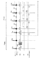
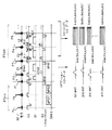
図15に、高速SE法のパルスシーケンスの一例を示す。RFパルスとしては、励起RFパルスP1および反転(リフォーカス)RFパルスP2〜Pnが、それぞれスライス方向傾斜磁場Gsと共に順次印加される。反転RFパルスP2〜Pnの印加に応答してエコー信号E1〜Enが得られるが、このエコー信号はそれぞれ読み出し方向傾斜磁場Grを印加した状態で読み出される。また、エコー信号E1〜Enのそれぞれには、大きさの異なる位相エンコード方向傾斜磁場GeのパルスPE1,PE3,P5〜が印加される。これにより、エコー信号は、K空間上の対応する位相エンコード位置にマッピングされ、フーリエ変換法により実空間画像に再構成される。なお、上述のRFパルスの送信位相はCPMGパルス系列に従う「X,Y,Y,Y,…)になっている。
【0005】
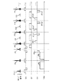
この高速SE法を適用した応用シーケンスとしては、文献「David c.Alsop, "Phase Insensitive Preparation of Single-Shot RARE: Application to Diffusion Imaging in Humans", MRM 38:527-533 (1997) 」により、シングルショットのディフュージョン(拡散強調)画像を撮影するパルスシーケンスが提案されている。このパルスシーケンスを図16に示す。同図において、P1は励起RFパルス、P2〜Pnは反転(リフォーカス)RFパルス、Gsはスライス方向傾斜磁場、Grは読み出し方向傾斜磁場、Geは位相エンコード方向傾斜磁場をそれぞれ示す。
【0006】
このパルスシーケンスでは、さらに、以下のような特徴が付加されている。PRパルスの送信位相は、CPMGパルス系列のものではなく、最初の励起RFパルスP1のみ90°ずれた値に設定され、全体として、「Y,Y,Y,Y,…」または「−Y,Y,Y,Y,…」になっている。また、それらのRFパルス列の時間的前に別のRFパルスPa、Pbがスライス選択的に設定される。この内、2番目のRFパルスPbの時間的前後には、拡散強調用の傾斜磁場パルス(MPG:Motion Probing Gradient )Ma,Mbが所定方向の傾斜磁場Gmpとして印加される。さらに、2番目のRFパルスPbと励起RFパルスP1との間にて、位相エンコード方向に一定の時間積分値の傾斜磁場パルスPEaを加える。さらに、反転RFパルスP2以降の位相エンコード方向傾斜磁場Geに対しても、上述した図16の位相エンコード方向傾斜磁場Ge=PE1〜PE6…に上記傾斜磁場パルスPEaと同量の時間積分値を加えた傾斜磁場パルスGe=PE1′〜PE6′…が印加され、エコー信号E1〜E3...が収集される。これにより、各エコー信号には、それぞれ異なる大きさの位相エンコードが施され、上述と同様にK空間へのマッピングを介して再構成される。
【0007】
このように拡散強調イメージングにあっては、ボクセル内のランダムな動きの水分子からの信号を消去するMPGパルスが印加され、生体組織内の分子拡散運動を強調した画像が得られる。MPGパルスは、分子の微小な動きに対する感度を得るため、その強度は大きく、印加時間も長くなっている。このため、診断対象それ自体の僅かな動き(体動など)が大きな位相シフトを起こし、アーチファクトの原因になる。
【0008】
このアーチファクトを抑制するには、1つの対策として、シングルショットEPI法などのように、全てのデータを1回の励起で収集してしまうという方法がある。このように収集すると、体動に起因した位相シフトが全てのエコーデータでほぼ同じ程度になるので、アーチファクトが抑制される。この方法によれば、したがって、特別な後処理も必要なく、比較的容易にアーチファクトの少ない画像が得られる。しかし、データ収集の時間が制約されるので、スライスの面内分解能があまり良くないという欠点があった。
【0009】
これに対して、複数回の励起に分割して全てのデータを収集するイメージングにおいて体動アーチファクトを抑制するには、ナビゲータエコー法が知られている(例えば、「R.J.Ordidge et al., "CORRECTION OF MOTIONAL ARTIFACTS IN DIFFUSION-WEIGHTED MR IMAGES USING NAVIGATION ECHOES", Magnetic Reso-nance Imaging, Vol.12, No.3, pp.455-460, 1994 」参照)。このナビゲータエコー法は、ナビゲータエコーという位相エンコードを印加していないエコーデータを画像再構成用エコーデータとは別に収集し、このナビゲータエコーのデータから体動に因る位相シフト量を各励起毎に求め、その位相シフト分だけ後処理により戻す(補正する)という手法である。ナビゲータエコー法を使用すれば、1回の励起で全データを収集する必要が無いので、面内分解能やS/Nを自由に調整でき、また3D−FT法による撮影も容易に行える。その反面、位相シフト量を計測するときの誤差などに因って、体動アーチファクトを完全には抑制できないというデメリットも併せ持っている。
【0010】
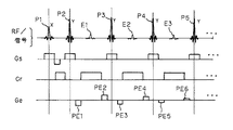
ところで、血流などの流れの情報をイメージングするフローイメージング法としては、図17に示すように、FE(フィールドエコー)法を利用した位相コントラスト(Phase Contrast)法が知られている。同図において、P11,P12は励起RFパルス、E11,E12はエコー信号、Gsはスライス方向傾斜磁場、Grは読み出し方向傾斜磁場、Geは位相エンコード方向傾斜磁場、および、Gfeはフローエンコード傾斜磁場をそれぞれ示す。フローエンコード傾斜磁場Gfe=Faを印加したパルスシーケンスで1組のエコーデータが収集され、またフローエンコード傾斜磁場Gfe=Fbを印加したパルスシーケンスでもう1組のエコーデータが収集される。各組のエコーデータが個別に再構成され、得られた2つの複素画像IA,IB間の画素毎の差分画像ICが演算される。この場合、エコーデータ(生データ)の段階で複素差分が演算し、その後に再構成してもよい。
【0011】
【発明が解決しようとする課題】
しかしながら、上述した従来の高速SE法の場合、CPMGパルス系列のRFパルスを採用しているため、その特性上、第2番目以降のRFパルスの印加位相と第2番目のRFパルスを印加する時の横磁化の位相との差の程度によって、後続のエコーの振幅が変化するという問題がある。このため、高速SE法は、T1強調画像、T2強調画像など、画素値の絶対値を利用する画像を得るには問題無く利用できるが、位相コントラスト法による流速測定、ナビゲーションエコー法よる体動アーチファクト補正、静磁場不均一性の測定など、画像の位相情報を利用する場合には、適用できなかった。
【0012】
このため、かかる補正、測定などを行う場合、通常SE法、FE法、またはEPI法を利用するしか手立てがないが、通常SE法、FE法は撮影時間が長く、一方、EPI法は磁場不均一による形態の歪みが大きいなどの別の問題があり、これを甘んじて受ける必要があった。
【0013】
本発明は、上述した従来の高速SE法と位相情報を利用した応用とを取り巻く不便な状況に鑑みてなされたもので、撮影の高速化と静磁場の不均一性に対する高い耐性とを維持し、かつ、エコー信号からスピンの位相情報を利用した種々の画像などの情報を得ることができる、改善した高速SE法によるMR撮影法を実行するMR装置を提供することを、その目的とする。
【0014】
【課題を解決するための手段】
本発明は、CPMGパルス系列に従うデータ収集シーケンスを改善して上記目的を達成しようとするものである。その構成の骨子は、高速SEシーケンスの最初の励起RFパルスの位相をCPMGパルス系列のそれから90°だけずらし、その変形した高速SEシーケンスの前に、前置励起RFパルスを含むパルス列を前置的に付加し、さらに、前置励起RFパルスと変形高速SEシーケンスの最初の励起RFパルスとの間、および、その変形高速SEシーケンスの反転RFパルスの間にスポイラー傾斜磁場パルスを挿入する、ことである。
【0015】
これにより、前置励起RFパルスと変形RAREシーケンスの最初の励起RFパルスとの間で横磁化が受ける位相変化を反映したエコー信号を得ることができ、このエコー信号を適宜にデータ処理することで位相を利用した画像データ、スペクトロスコピー、位相分布データなどを得ることができる。
【0016】
具体的な本発明の構成は以下のようである。
【0017】
本発明に係るMR装置は、時間軸上の最初に位置する前置励起RFパルスおよび前記前置励起RFパルスよりも後に位置する前置反転RFパルスを少なくとも含む第1のパルス列を前置的に被検体に印加する第1の印加手段と、送信位相がCPMGパルス系列に従う最初のパルス送信位相よりも90°ずらして設定された励起RFパルスと送信位相がCPMGパルス系列に従う2番目以降のパルス送信位相と同じに設定された複数個の反転RFパルスとを含む第2のパルス列を前記第1のパルス列を前置的に印加した後に前記被検体に時系列に印加する第2の印加手段と、前記前置励起RFパルスの印加と前記励起RFパルスの印加との間の期間内に及び前記複数個の反転RFパルスのそれぞれの印加後に、一定の時間積分値を有するスポイラーパルスを所望の傾斜磁場方向に発生させて前記被検体に印加する第3の印加手段と、前記前置励起RFパルスの印加と前記励起RFパルスの印加との間の期間であり、かつ前記前置反転RFパルスの時間軸上前後の位置において組織拡散の程度に応じて、前記複数個の反転RFパルスに応答して発生する複数個のエコー信号の強度を変化させるMPGパルスを所望の傾斜磁場方向にそれぞれ印加する第4の印加手段と、前記複数個のエコー信号を収集して位相情報に関わるデータ処理を行うデータ処理手段と、を備えたことを特徴とする。
【0025】
また、上述の構成において、前記複数個のエコー信号の内の少なくとも1個のエコー信号に付与する位相エンコードを零とし且つ残りのエコー信号に付与する位相エンコードをイメージング必要量とする位相エンコード用傾斜磁場を印加する第5の印加手段を備え、前記データ処理手段は、前記位相エンコードが零のエコー信号に応じたエコーデータを収集して当該エコーデータが有する位相情報を演算する手段と、この位相情報から前記被検体の体動に拠る位相シフト量を演算する手段と、前記位相エンコードとしてイメージング必要量を与えるエコー信号に応じたエコーデータを収集して当該エコーデータの位相を前記位相シフト量に基づき補正する手段とを備える、ことができる。
【0027】
【発明の実施の形態】
以下、本発明の実施の形態を図面を参照して説明する。
【0028】
第1の実施の形態
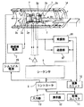
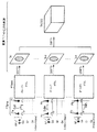
第1の実施形態を図1〜図3を参照して説明する。この実施形態にかかるMRI(磁気共鳴イメージング)装置の概略構成を図1に示す。
【0029】
このMRI装置は、被検体Pを載せる寝台部と、静磁場を発生させる静磁場発生部と、静磁場に位置情報を付加するための傾斜磁場発生部と、高周波信号を送受信する送受信部と、システム全体のコントロール及び画像再構成を担う制御・演算部とを備えている。
【0030】
静磁場発生部は、例えば超電導方式の磁石1と、この磁石1に電流を供給する静磁場電源2とを備え、被検体Pが遊挿される円筒状の開口部(診断用空間)の軸方向(Z軸方向)に静磁場H0 を発生させる。なお、この磁石部にはシムコイル14が設けられている。このシムコイル14には、後述するコントローラの制御下で、シムコイル電源15から静磁場均一化のための電流が供給される。寝台部は、被検体Pを載せた天板を磁石1の開口部に退避可能に挿入できる。
【0031】
傾斜磁場発生部は、磁石1に組み込まれた傾斜磁場コイルユニット3を備える。この傾斜磁場コイルユニット3は、互いに直交するX、Y、Z軸方向の傾斜磁場を発生させるための3組(種類)のx,y,zコイル3x〜3zを備える。傾斜磁場部はさらに、x,y,zコイル3x〜3zに電流を供給する傾斜磁場電源4を備える。この傾斜磁場電源4は、後述するシーケンサ5の制御のもと、x,y,zコイル3x〜3zに傾斜磁場を発生させるためのパルス電流を供給する。
【0032】
傾斜磁場電源4からx,y,zコイル3x〜3zに供給されるパルス電流を制御することにより、物理軸としての3軸であるX,Y,Z方向の傾斜磁場を合成して、論理軸としてのスライス方向傾斜磁場Gs、位相エンコード方向傾斜磁場Ge、および読出し方向(周波数エンコード方向)傾斜磁場Grの各方向を任意に設定・変更することができる。スライス方向、位相エンコード方向、および読出し方向の各傾斜磁場は静磁場H0 に重畳される。
【0033】
送受信部は、磁石1内の撮影空間にて被検体Pの近傍に配設されるRFコイル7と、このコイル7に接続された送信器8T及び受信器8Rとを備える。この送信器8T及び受信器8Rは、後述するシーケンサ5の制御のもとで、磁気共鳴(MR)現象を誘起させるためのラーモア周波数のRF電流パルスをRFコイル7に供給する一方、RFコイル7が受信した高周波のMR信号を受信し、各種の信号処理を施して、対応するデジタル信号を形成するようになっている。
【0034】
さらに、制御・演算部は、シーケンサ5、コントローラ6、演算ユニット10、記憶ユニット11、表示器12、および入力器13を備える。この内、コントローラ6はコンピュータを有し、このコンピュータに記憶させたソフトウエア手順により、シーケンサ5にスキャンシーケンス情報を指令するとともに、シーケンサ5を含む装置全体の制御ブロックの動作タイミングの同期をとりながら、それらの制御を統括する機能を有する。
【0035】
シーケンサ5は、CPUおよびメモリを備えており、コントローラ6から送られてきたパルスシーケンス情報を記憶し、この情報にしたがって傾斜磁場電源4、送信器8T、受信器8Rの一連の動作を制御する。ここで、パルスシーケンス情報とは、一連のパルスシーケンスにしたがって傾斜磁場電源4、送信器8Rおよび受信器8Tを動作させるために必要な全ての情報であり、例えばx,y,zコイル3x〜3zに印加するパルス電流の強度、印加時間、印加タイミングなどに関する情報を含む。
【0036】
また、演算ユニット10は、受信器8RからのMR信号のデジタルデータを入力して内蔵メモリで形成されるフーリエ空間(k空間または周波数空間とも呼ばれる)への生データ(原データとも呼ばれる)の配置、および、生データを実空間画像に再構成するための2次元または3次元のフーリエ変換処理を行うようになっている。また、演算ユニット10は、3次元画像データから2次元画像を生成するためにMIP(最大値投影)処理なども実施できるようになっている。
【0037】
記憶ユニット11は、生データおよび再構成画像データのみならず、演算処理が施された画像データなどを保管することができる。表示器12は画像を表示する。また、術者は入力器13を介して所望のスキャン条件、スキャンシーケンス、画像処理法などの必要情報をコントローラ6に入力できるようになっている。
【0038】
次に、この実施形態の動作を、本発明のイメージング原理と共に説明する。
【0039】
本実施形態では、本発明に係る改善した高速SE法を位相コントラスト(Phase Contrast)法に適用してフローイメージングを行う。このイメージングでは、スキャンは2回実施される。
【0040】
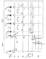
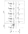
この2回のスキャンに使用するパルスシーケンスを図2に示す。同図は、2回のスキャンのパルスシーケンスを同一図面上で同時に表している。後述するように、2回のパルスシーケンスの違いはフローエンコード用傾斜磁場Gfeのパルス波形の極性にある。
【0041】
1回目のスキャンAを説明する。1回目のスキャンAのパルスシーケンスは、図2、3に示す如く、CPMGパルス系列を利用したデータ収集パルス列PTacqと、このデータ収集パルス列PTacqの実行前に印加するプリパルス列PTpreとを含む。
【0042】
プリパルス列PTpreは、最初に印加する前置励起RFパルスPaと、この前置励起RFパルスPaと並行して印加するスライス方向傾斜磁場パルスGsと、この両パルスPaおよびGsを印加した後のデータ収集パルス列PTacqを印加までの期間で印加するフローエンコードパルス用傾斜磁場パルスGfe=Faとを含む。前置励起パルスPaは、例えば所望のRF周波数の信号をSINC関数で変調した90°パルスとして形成される。フローエンコード用傾斜磁場パルスGfe=Faは、最初に負方向に立ち下がる矩形パルスと、その後で正方向に極性反転する矩形パルスとから成る。このフローエンコード用傾斜磁場の印加方向は、描出したい方向に応じて任意に設定できる。例えば、スライス方向、読み出し方向、および位相エンコード方向のいずれかであってもよいし、その内の複数の方向に同時に印加してもよい。また、それらの3方向を個別に印加し、3つの画像を加算することで任意方向を画像化する場合であってもよい。
【0043】
データ収集パルス列PTacqは、1個目のRFパルスである励起RFパルス(90°RFパルス)P1と、この励起RFパルスP1と並行して印加するスライス方向傾斜磁場パルスGsとを含む。このスライス方向傾斜磁場パルスGsにおいて、先に印加する負極性の矩形波P1aは、パルスPa〜P1間で印加されるスライス方向の傾斜磁場の時間積分値を零にするためのリワインドパルスであり、その後の正極性側に反転したスライス選択用矩形波P1bを経て、再び負極性に反転する矩形波P1cは、パルスP1〜P2間で印加されるスライス方向の傾斜磁場の時間積分値を零にするためのリワインドパルスである。
【0044】
このパルス列PTacqはさらに、その後に印加する、リフォーカスおよびエコーデータ収集用のパルス群を含む。このパルス群としては、一定間隔で印加されるリフォーカス用の反転RFパルス(180°RFパルス)P2〜P5…と、この反転RFパルスのそれぞれと並行して印加するスライス方向傾斜磁場パルスGsとを含む。さらに、このパルス群は、複数の反転RFパルスのそれぞれに応答して発生するエコー信号E1〜E3…を個別に収集するための読み出し方向傾斜磁場パルスGrと、この読み出しに際して各エコー信号に互いに異なる強度の位相エンコードを付加する位相エンコード方向傾斜磁場パルスGeとを含む。
【0045】
データ収集パルス列PTacqにRFパルスとして用意されている励起RFパルスP1および反転RFパルスP2〜P5…は、その印加位相が「Y,Y,Y,Y,…」または「−Y,Y,Y,Y,…」に設定されている。つまり、CPMGパルス系列の送信印加位相「X,Y,Y,Y,…」を踏襲しつつも、最初の励起RFパルスP1の送信印加位相を90°ずらして設定されている。
【0046】
また、このデータ収集パルス列PTacqにおいて、位相エンコード方向傾斜磁場パルスGeは、図2に示す如く、エコー信号E1〜E3…に異なるエンコード量を与える位相エンコードパルスGencと、所定方向に一定の時間積分値を有するディフェーズ用のスポイラーパルスGspoとを合成して設定されている。この例では、スポイラーパルスGspoは、図2において負方向に立ち下がる、強度Gαを一定時間積分した値を有する矩形パルスとして設定されている。
【0047】
位相エンコードパルスGencおよびスポイラーパルスGspoは共に、図示の如く、エコー信号収集後に印加する逆極性のリワインディングパルスを伴っている。
【0048】
スライス方向傾斜磁場GsおよびRFパルスの周波数は、被検体の所望位置のスライスを選択できるようにその強度および値が設定されている。
【0049】
なお、スポイラーパルスGspoの最初のパルスSPO1はデータ収集パルス列PTacqの一部として説明したが、この最初のパルスSPO1は前置励起RFパルスPaの印加後であって励起RFパルスP1の印加前の期間内にいずれかのタイミングで印加すればよい。
【0050】
一方、2回目のスキャンBのパルスシーケンスは、図2、3に示す如く、全体としては1回目のスキャンAと同様であるが、プリパルス列PTpreの中で印加するフローエンコードパルス用傾斜磁場パルスGfeの極性が1回目と反対になっている。つまり、このフローエンコード用傾斜磁場パルスGfe=Fbは、最初に正方向の矩形波として立ち下がり、その後に負方向に極性反転する矩形波が続くようになっている。その他のパルス波形、パルス印加タイミングは1回目と同じに設定してある。
【0051】
シーケンサ5は、コントローラ6から1回目のスキャンA開始の指令を受けると、図2に示すスキャンA用のパルスシーケンスを実行する。最初に、傾斜磁場電源4および送信器8Tを駆動して、プリパルス列PTpreにおける前置励起RFパルスPaがスライス方向傾斜磁場Gsと共にスライス選択的に印加される。これにより、原子核スピンは90°フリップしてX′−Y′面(回転座標)まで倒れる。この後、フローエンコードパルスFaが印加される。このフローエンコードパルスFaの最初の矩形パルスによる傾斜磁場がスピンに位相ずれを与える。そして、2つ目の極性反転した矩形パルスによる傾斜磁場がスピンの位相を元に戻すように働く。この2つの矩形パルスの印加の間にスピンの位置が変化していない場合、フローエンコードパルスFa印加後の位相は変わらないが、スピンが動いていた場合、その位相は変化する。つまり、後続のデータ収集パルス列PTacqが印加される直前に、スピンにその動きに応じた横磁化の位相情報が与えられる。
【0052】
この後、シーケンサ5によって、データ収集パルス列PTacqの実行が順次指令される。この実行により、反転RFパルスP2〜を印加する度にエコー信号E1〜が生成される。このとき、位相エンコード方向にスポイラーパルスGspoを印加しているので、励起RFパルスP1で初めて励起されるエコー成分を十分に抑制しつつ、前置励起RFパルスPaで励起されたエコー成分を収集することができる。エコー信号E1〜は位相エンコード方向傾斜磁場Geにより所要の位相エンコード量が与えられ、かつ、読み出し方向傾斜磁場Grと共に読み出される。1回目のスキャンAのエコー信号E1〜がRFコイル7を介して時系列に受信され、受信器8Tに送られる。
【0053】
受信器8Rにおいて、エコー信号は、増幅、中間周波変換、位相検波、低周波増幅などの所定の処理に付された後、A/D変換処理されてデジタル量のエコーデータに変換される。このエコーデータは演算ユニット10に送られ、2次元のk空間に対応したメモリ領域に位相エンコード量に対応して配置される。演算ユニット10は、例えばk空間へのエコーデータの配置が完了した時点で、コントローラ6からの指令の元に、その1組のエコーデータに2次元フーリエ変換を施し、実空間画像に再構成する。このようにして生成された、1回目のスキャンAに係る所望スライスの第1の画像Iaのデータは演算ユニット10の内蔵メモリまたは記憶ユニット11に一時保管される。
【0054】
この後、上述と同様にして、シーケンサ5は2回目のスキャンBを実行する。このときには、プリパルス列PTpreの中で印加されるフローエンコードパルスFbの極性が1回目スキャン時のときとは反対の順に制御される。このため、横磁化に倒れたスピンの位相情報も逆極性となる。この2回のスキャンBによって、1回目スキャン時と同様に、もう1組のエコーデータが得られ、第2の画像Ibが生成される。
【0055】
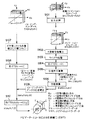
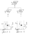
このようにして2回のスキャンA,Bおよびそのデータ収集、再構成が完了すると、コントローラ6は、演算ユニット10に第1、第2の画像Ia,Ibの2組のデータに対する複素差分を指令する(図3のフロー説明部分を参照)。これに応答して演算ユニット10は、2組のデータの間で対応画素毎の複素差分を演算し、最終画像Icの1組のデータを生成する。このデータは必要に応じて記憶ユニット11に格納されるとともに表示器12で画像Icとして表示される。位相分布は、最終画像Icの実数部、虚数部の画像データからtan−1を演算することで計算でき、血流等の流速が求められる。
【0056】
なお、上述の複素差分の処理は、2組のエコーデータが生データの段階で、相互に差分演算して1組の差分データを生成し、これを再構成して最終画像Icを得るようにしてもよい。
【0057】
以上によって、各エコー信号E1〜は、フローエンコード傾斜磁場Gfe(=Fa,Fb)の印加に伴って、前置励起RFパルスPaの印加からCPMGパルス系列の最初の励起RFパルスP1の印加までの期間に、スピンの横磁化が受ける位相変化を、位相成分として確実に反映されたエコー信号となる。つまり、2回のスキャンA,Bによって得られる第1、第2の画像Ia,Ibは、その位相変化を反映した画像である。そこで、この第1、第2の画像Ia,Ibの複素差分をとることで、かかる位相変化のみを抽出した画像を得ることができる。
【0058】
これにより、CPMGパルス系列を踏襲した高速SE法であっても、血流速などを測定できる高画質の位相コントラスト像(フロー像)を得ることができる。したがって、位相コントラスト像を撮影するときに、従来のように通常SE法やFE法を使用する必要がなく、撮影時間を短縮できる。また、従来のようにEPI法を使用する必要も無くなるから、静磁場の不均一性の影響を受けにくく、形態歪みを抑制でき、またサセスタビリティに強いという利点も得られる。
【0059】
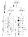
なお、本発明に係るスポイラーパルスGspoは、図2に記載のものに限定されることなく、図4に表すように印加してもよい。つまり、図2の場合には、CPMGパルス系列の2番目以降のRFパルス、すなわち最初の反転RFパルスP2以降のRFパルス間に印加するスポイラーパルスSPO2〜は、最初のスポイラーパルスSPO1と同方向(同極性)で、しかも同量の時間積分値を持つが、図4の場合には、そのスポイラーパルスSPO2〜は、最初のスポイラーパルスSPO1と反対方向(反対極性)で、しかも同量の時間積分値を持つように設定してある。この図4記載のスポイラーパルスの印加法によっても、図2のものとは別のエコー成分を同様に画像化でき、同様に流速情報を得ることができる。
【0060】
第2の実施形態
本発明の第2の実施形態を図5に基づき説明する。これ以降の実施形態において、上述した第1の実施形態の構成要素と同一または同等の要素には同一符号を用いて、その説明を省略または簡略化する。
【0061】
この第2の実施形態では、第1の実施形態で説明したパルスシーケンスを変形して実行し、位相コントラスト法に拠るフローイメージングを行うことを特徴とする。
【0062】
この実施形態のMRI装置のハード的構成は、第1の実施形態のものと同一である。シーケンサ5は、図5に示すパルスシーケンスを2回のスキャンで実行するようになっている。演算ユニット10は、前述した図3の処理と同様に、2回のスキャンで得た2組のエコーデータの再構成およびその2枚の画像データ間での複素差分演算を行うようになっている。
【0063】
図5に示す如く、このプリパルス列PTpreでは、第1の実施形態のものに比較し、RFパルスが1個追加されている。つまり、最初の前置励起RFパルスPaの印加から所定時間T/2が経過した後で反転(リフォーカス)RFパルスPbが印加されるようになっている。ここで時間Tは、最初の前置励起RFパルスPaの印加からデータ収集パルス列PTacqの最初の励起RFパルスP1の印加までの時間である。このように、前置励起RFパルスPaから前置反転RFパルスPbまでの時間幅T/2と、前置反転RFパルスPbから最初の励起RFパルスP1までの時間幅T/2とを等しく設定することができ、そのように設定することは、画像の位相成分が静磁場の不均一度の大小に影響されず、変化しないという有利さがある。
【0064】
前置反転RFパルスPbは例えば180°RFパルスで形成され、かつ、スライス方向傾斜磁場パルスGsと共に印加される。
【0065】
このプリパルス列PTpreでは、さらに、前置反転RFパルスPbの時間軸上の前後に、印加時間が比較的長く、高強度で、かつ等量の矩形状のフローエンコード用傾斜磁場GfeのパルスFc(又はFd)がそれぞれ印加される。1回目のスキャンAのときは、2つの矩形状のフローエンコードパルスFc(図5中の実線参照)はいずれか一方の極性(例えば正極性)に印加され、反対に、2回目のスキャンBのときは、2つの矩形状のフローエンコードパルスFd(図5中の点線参照)はその逆極性(例えば負極性)に印加される。このフローエンコードパルスパルスFcまたはFdにより位相分散が強調される。
【0066】
データ収集パルス列PTacqは、第1の実施形態のものと同一に設定されている。
【0067】
本実施形態では、シーケンサ5の指令の元に、フローエンコード用傾斜磁場Gfeの極性(方向)を変えて、このパルスシーケンスに基づくスキャンA、Bが2回行われてエコーデータがそれぞれ収集される。この2組のエコーデータは、演算ユニット10によって、第1の実施形態のときと同様に再構成、複素差分演算、位相演算などを処理に付される。このため、位相コントラスト法による流速画像が得られる。
【0068】
この実施形態によっても、第1の実施形態と同等の作用効果が得られる。とくに、前置反転RFパルスPbを追加したので、静磁場不均一性が大きい場合でも、ピクセル内の位相分散に因るエコー信号の低下を抑制したデータを収集でき、S/Nを向上させることができる。
【0069】
第3の実施形態
本発明の第3の実施形態を図6に基づき説明する。この実施形態に係るMRI装置は、本発明を磁場分布測定に適用したことを特徴とする。
【0070】
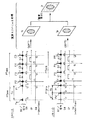
このMRI装置では、シーケンサ5は図6に示すスキャンA,Bに対応した2通りのパルスシーケンスを実行する。この2組のパルスシーケンスは共に、前述したと同一または同様のデータ収集パルス列PTacqを基礎とし、その実行までの時間幅の互いに異なるプリパルス列PTpreを印加するように設定したものである。
【0071】
この内、スキャンAのパルスシーケンスにおけるプリパルス列PTpreは、スライス方向傾斜磁場Gs(その強度はデータ収集パルス列PTacqのものと同じ)と共に印加する前置励起RFパルスPaを含む。この前置励起RFパルスPaの印加からデータ収集パルス列PTacqの最初の励起RFパルスP1の印加までの時間幅は所定時間Taに設定されている。これに対し、スキャンBのそれにおけるプリパルス列PTpreでは、上述の時間幅が所定時間Tb(<Ta)に設定されている。つまり、スキャンAにおける時間幅Taに対して、スキャンBのそれは時間dTだけ短縮されている。
【0072】
このように前置励起RFパルスPaから最初の励起RFパルスP1までの時間幅(エコータイム)を違えてスキャンA,Bをそれぞれ実行すると、収集される各組のエコーデータには時間幅Ta(またはTb)に相当する時間幅と各空間位置の静磁場不均一性に比例した位相変化が反映される。
【0073】
そこで、演算ユニット10は、各組の収集エコーデータを個別に再構成し、互いの再構成データの複素差分を画素毎に演算する。この差分画像の位相演算により、磁場分布を測定できる。例えば、上述の例で言えば、時間幅の差=Ta−Tb=4.8msに設定した場合、静磁場強度1.5Tにおいて、3.2ppmの磁場不均一性がある位置の位相差は360°になる。このように位相差を介して撮影対象の磁場分布が測定される。
【0074】
第4の実施形態
本発明の第4の実施形態を図7に基づき説明する。この実施形態に係るMRI装置は、本発明を磁場分布スペクトルに適用したものである。
【0075】
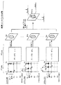
このMRI装置では、シーケンサ5は、図7に示すスキャンN1〜Nnまでの複数n回に個別に対応した複数n組のパルスシーケンスを実行する。この複数n組のパルスシーケンスも共に、第3の実施形態と同様のデータ収集パルス列PTacqを基礎とし、その実行までの時間幅の互いに異なるプリパルス列PTpreを印加することを特徴とする。
【0076】
例えば、図7に示す如く、前置励起RFパルスPaの印加からデータ収集パルス列PTacqの最初の励起RFパルスP1の印加までの時間幅Tiは、1回目のスキャンN1では所定値に、m回目のスキャンNmでは所定値よりもdT′だけ短縮され、n回目のスキャンNnでは所定値よりもdT”だけ短縮されるといった具合である。
【0077】
このn通りのパルスシーケンスによってそれぞれ収集される各組のエコーデータは、時間幅Tiと空間各位置の静磁場不均一度に比例した位相変化を起こしている。そこで、演算ユニット10は、各組のエコーデータを2次元フーリエ変換(2DFT)して実時間の画像In1〜Innに再構成する。次いで、演算ユニット10は、その複数枚の画像In1〜Innの同一ピクセル位置の画素データをそれぞれ一連のデータと見做して1次元のフーリエ変換を行うことで、各ピクセルの周波数スペクトルを演算する。この演算を全部のピクセルに対して行い、各ピクセルの周波数スペクトル分布情報を有する1枚の画像Ispecをつくる。これにより、撮影対象の磁場分布スペクトルの測定ができる。
【0078】
通常SE法(1回の励起により1個のスピンエコーを得る方法)に基づく従来のスペクトロスコピーは、1エコーを収集する度に縦磁化の回復を待つ必要があるため、数百ミリ秒から数秒の間、次の収集を控えねばならなかった。したがって、画像再構成に必要な全データを収集するには、数十分程度の非常に長い時間が掛かっていた。しかし、このMRI装置を用いてスペクトロスコピーを行う場合、1回の繰り返し時間TRで数十から数百個のエコー信号を収集することができるので、撮影時間の大幅な短縮、画像の空間分解能向上、または、周波数スペクトルの分解能向上を期することができる。
【0079】
第5の実施形態
さらに、第5の実施形態を図8、9に基づき説明する。この実施形態のMRI装置は、本発明に係るデータ収集法をSE(スピンエコー)タイプの3次元撮影に応用したイメージングを実施できる。
【0080】
図8に、コントローラ6の制御下でシーケンサ5により実行される3次元撮影のパルスシーケンスを示す。
【0081】
このパルスシーケンスもプリパルス列PTpreおよびデータ収集パルス列PTacqから成る。プリパルス列PTpreは、図示の如く、前置励起RFパルスPaおよび反転励起RFパルスPbを含み、共にスライス方向傾斜磁場Gsのパルスと共にスライス選択的に印加される。前置励起RFパルスPaおよび前置反転RFパルスPbを印加する間の期間に、スライス方向の位相エンコード(スライスエンコード)パルスGslが印加される。スライスエンコードパルスGslの強度(波形面積)は、このパルスシーケンスの繰り返し毎に、徐々に変化させて、所望の撮影ボリューム領域のスライス方向の位置情報を与えるようになっている。
【0082】
データ収集パルス列PTacqは、前述した各実施形態のものと同一または同等である。
【0083】
シーケンサ5により、スライスエンコードパルスGslの強度を変えながら、上述のパルスシーケンスが複数回実行される。これにより、各回で1組のエコーデータが収集される。図9に示す如く、この各組のエコーデータは演算ユニット10により2次元フーリエ変換されて複数n枚の画像Ix1〜Ixnに再構成される。演算ユニット10はさらに、この複数n枚の画像の互いに対応する同一位置の画素データをそれぞれ一連のデータと見做して1次元のフーリエ変換を行う。この変換により、各画素位置のスライス方向の信号分布が求められて、3次元の画像Ixのデータに再構成される。
【0084】
このように、SE(スピンエコー)タイプのプリパルス列PTpreにおいて、位相情報を与えるパルスとしてスライスエンコードを用いることにより、3次元撮影も好適に行うことができる。
【0085】
第6の実施形態
第6の実施形態を図10に基づき説明する。この実施形態のMRI装置も、本発明に係るデータ収集法をFE(フィールドエコー)タイプの3次元撮影に応用したイメージングを実施する。ここで用いる「FEタイプ」とは、FE法に拠る画像のように、静磁場の不均一に応じて位相成分が変化する」、ことを意味している。なお、前述したように、前置励起RFパルスPaの印加から前置反転RFパルスPbの印加までの時間と、前置反転RFパルスPbの印加から最初の励起RFパルスP1の印加までの時間とが等しい場合、SE法の画像のように、静磁場の不均一によっては位相成分が変化しないので、「SEタイプ」として対比できる。
【0086】
図10に、コントローラ6の制御下でシーケンサ5により実行される3次元撮影のパルスシーケンスを示す。
【0087】
このパルスシーケンスもプリパルス列PTpreおよびデータ収集パルス列PTacqから成る。プリパルス列PTpreは、図示の如く、前置励起RFパルスPaのみを含み、スライス方向傾斜磁場Gsのパルスと共にスライス選択的に印加される。前置励起RFパルスPaが印加された後に、スライス方向の位相エンコード(スライスエンコード)パルスGslが第5の実施形態のときと同様に印加される。データ収集パルス列PTacqは、前述した各実施形態のものと同一または同等である。
【0088】
このパルスシーケンスを実行して収集されたエコーデータは、前述した図9と同様に処理される。これにより、SEタイプのときと同様に、プリパルス列PTpreが「FEタイプ」である3次元撮影が好適に実施できる。
【0089】
なお、本発明に係る、CPMGパルス系列を基礎とする改善した高速SE法は、プリパルス列の段階で画像の位相成分に何等かの情報を反映させることを要旨としているが、この実施の態様としては上述した実施形態のものに限定れない。例えば、温度計測、エラストグラフィーなども、この手法で実施できる。
【0090】
また、演算ユニット10によって行われるデータ収集後の処理において、複素差分を演算する必要がある場合、各組のエコーデータ同士を最初に複素差分し、その後に、差分結果に係るエコーデータを再構成処理するようにしてもよい。
【0091】
さらに、前述した実施形態において連続撮影を行う場合、スキャンA,Bを交互に且つ連続して行い、時間的に隣接した2組ずつの画像データの複素差分演算を行って、連続的に処理画像を表示することもできる。
【0092】
第7の実施形態
第7の実施形態を図11、12を参照して説明する。
【0093】
この実施形態のMRI装置は、本発明の改善した高速SE法を2D拡散強調イメージング(2D−DWI)で適用し、これにナビゲーターエコー法を組み込んだイメージング法を実施することを特徴とする。
【0094】
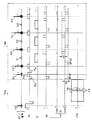
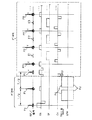
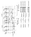
図11には、シーケンサ5によって指令される2次元拡散強調イメージングのパルスシーケンスを示す。このパルスシーケンスは、プリパルス列PTpreおよびデータ収集パルス列PTacqから成る。プリパルス列PTpreでは、前置励起RFパルスPaと前置反転RFパルスPbとがこの順に一定間隔を置いてスライス方向傾斜磁場Gsと共に印加される。前置反転RFパルスPbの時間軸上の前後において、水分子のスピンの位相分散を強調するMPG(Motion Pro- bing Gradient)用傾斜磁場Ggmpとして矩形状のパルスMPG1、MPG2が任意の1つまたは複数の傾斜磁場印加方向に夫々印加されている。このパルスMPG1、MPG2は共に同極性で同一の波形面積を有し、しかも、比較的に高い強度、長い印加時間に設定されている。
【0095】
一方、データ収集パルス列PTacqは、ナビゲーターエコーEnavの収集を除いて前述した実施形態のものと同一である。ナビゲーターエコーEnavはここでは第1エコー信号E1を当てており、この第1エコー信号E1=ナビゲーターエコーEnavを収集するときは、図に示す如く、位相エンコード方向傾斜磁場Geの位相エンコードパルスGenc=0に設定され(このときスポイラーパルスSPO2とそのリワインディングパルスSPO2′のみが印加される。図11参照)、読み出し方向傾斜磁場GrのパルスGrnavのみが印加される。なお、ナビゲーターエコーEnavを何番目のエコー信号にとるかは任意に設定できる。
【0096】
図11に示すパルスシーケンスを実行すると、その繰り返し時間TRに基づくショット(励起)毎に、第1エコー信号E1はナビゲーターエコーEnavとしてRFコイル7および受信器8Rにより収集され、ナビゲーション・エコーデータSnavi(Kx,nShot)に加工される。このナビゲーション・エコーデータは演算ユニット10に送られ、その内部メモリに記憶される。
【0097】
また、そのショット毎に第2エコー信号E2以降のエコー信号も同様に収集され、イメージング・エコーデータSim(Kx,nShot)に加工される。このイメージング・エコーデータは演算ユニット10に送られ、その内部メモリで仮想的に形成される2次元フーリエ空間Kに2次元イメージング・エコーデータSim(Kx,Ky)として配置される。
【0098】
演算ユニット10はナビゲーション・エコーデータおよびイメージング・エコーデータを入力すると、ナビゲーターエコー法の処理を行う。すなわちナビゲーション・エコーデータSnavi(Kx,nShot)から体動に拠る位相シフトを演算(計測)し、その演算値でイメージング・エコーデータSim(Kx,Ky)の位相を補正する。
【0099】
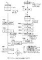
図12には、この位相補正処理の概要を示す。ナビゲーション・エコーデータSnavi(Kx,nShot)はまず、拡大処理に付されてK空間全体に拡大されたナビゲーション・エコーデータSnavi(Kx,Ky)に展開される(ステップS101)。具体的には、K空間の読み出し方向Kyの対応するイメージングデータと同じショットで収集したナビゲーション・エコーデータSnavi(Kx,nShot)でK空間を埋めることにより拡大される。
【0100】
拡大されたナビゲーション・エコーデータSnavi(Kx,Ky)は、K空間内での位相補正(ステップS102)、ウインドウ処理(ステップS103)に付された後、Kx方向を実空間の読み出し方向X方向に戻す1次元フーリエ変換(1DFT)が行われる(ステップS104)。この後、位相差分が演算されて、1回フーリエ変換されたK空間のナビゲーション・エコーデータSnavi(X,Ky)が求められる(ステップS105)。さらに、これから体動を表す位相データφnavi(X,Ky)が演算される(ステップS106)。
【0101】
一方、2次元のイメージング・エコーデータSim(Kx,Ky)は、演算ユニット10において、DCオフセット補正などの所望の補正処理に付された後(ステップS107)、Kx方向を実時間軸X方向に戻す1次元フーリエ変換(1DFT)が実行されてエコーデータSim(X,Ky)に加工される(ステップS108)。
【0102】
このイメージング・エコーデータSim(X,Ky)に対して、前述したように求めていた位相データφnavi(X,Ky)によりショット毎の位相補正がなされる(ステップS109)。この位相補正によって得られるイメージング・エコーデータScorim(X,Ky)は、さらに、K空間の位相エンコード方向Kyを実時間の位相エンコードY方向に戻す1次元フーリエ変換に付される(ステップS110)。これにより、ナビゲーターエコーに基づき体動補正された実空間の2次元像Vcorim(X,Y)が得られる。
【0103】
したがって、本実施形態の2D拡散強調イメージングによれば、前置励起RFパルスPaとCPMGパルス系列の最初の励起RFパルスP1との間で生じる位相変化を、位相成分として反映させた高速SEの画像が得られる。つまり、MPGパルスが生じさせる位相シフトを位相情報としてその画像に取り込むことができる。また、イメージング用のデータは同じショットで収集したナビゲーション・エコーデータから求めた位相量だけ元に戻されるから、体動に起因したアーチファクトを補正することができる。とくに、2次元の各ピクセル毎に位相変化を測定できるので、位相シフト量を計測するときの誤差が従来のナビゲーターエコー法よりも少なく、体動に因る位相シフトをより高精度に補正できる。また、高速SE法を使用するので、シングルショットEPI法を使用する従来法に比べて、データ収集時間の制約が少ないので、面内分解能が良いという利点がある。
【0104】
第8の実施形態
第8の実施形態を図13、14を参照して説明する。
【0105】
この実施形態のMRI装置は、本発明の改善した高速SE法を3D拡散強調イメージング(2D−DWI)で適用し、これにナビゲーターエコー法を組み込んだイメージング法を実施することを特徴とする。この3次元法は、第7の実施形態の2次元法を3次元に展開したことを基本とする。
【0106】
図13には、シーケンサ5によって指令される3次元拡散強調イメージングのパルスシーケンスを示す。このパルスシーケンスは、プリパルス列PTpreおよびデータ収集パルス列PTacqから成る。プリパルス列PTpreは第7の実施形態のもの同一である。
【0107】
データ収集パルス列PTacqには、そのスライス方向傾斜磁場Gsとしてスライスエンコード用パルスSLl,SL2,…が、そのリワインディングパルスSLl′,SL2′,…と共に図示の如く付加されている。また、ナビゲータエコーEnavは、ここでは第1エコー信号E1を当てているが、これはどのエコー信号をナビゲータ用に使用してもよい。そのほかのパルス形態は第7の実施形態のものと同様である。
【0108】
演算ユニット10は図14に示す手順概要に沿って、3次元のナビゲーターエコー法による位相補正を実施する。この処理も、前述した2次元のものを3次元に拡張したもので、ナビゲーション・エコーデータおよびイメージング・エコーデータ共に3次元のものを扱うことと、最終のフーリエ変換処理が2次元になっている(ステップS110′)ことが異なるだけである。この一連の処理により、3次元の拡散強調像Vcorim(X,Y,Z)が得られる。
【0109】
この結果、2次元の場合と同様に、イメージング・エコーデータは同じショット(RF励起)で収集したナビゲーション・エコーデータから求めた位相量分だけ、元の位相に戻され、体動の影響が的確にキャンセルされる。これにより、前述の2次元DWIのときと同等の効果を得る。
【0110】
なお、この実施形態では、あるスライスエンコード量印加したときに全ての位相エンコードに対するエコーデータを収集し、その後で、次のスライスエンコード量の印加に対するデータ収集に進むという手順で撮影を行っているが、スライスエンコードと位相エンコードはどのような順番で掛けてもよく、全体として3次元でエコーデータを収集できればよい。
【0111】
また、本発明は、代表的に例示した上述の実施の形態に限定されるものではなく、当業者であれば、特許請求の範囲の記載内容に基づき、その要旨を逸脱しない範囲内で種々の態様に変形、変更することができ、それらも本発明の権利範囲に属するものである。
【0112】
【発明の効果】
以上説明したように、本発明に係るMR装置によれば、前置励起RFパルスとデータ収集パルス列の最初の励起RFパルスとの間で生じる位相変化の影響を受けた位相成分を持つ高速SE法の画像データが得られる。
【0113】
したがって、撮影の高速化と静磁場の不均一性に対する高い耐性とを維持し、かつ、エコー信号からスピンの位相情報を利用した種々の画像などの情報を得ることができる。つまり、これまで高速SE法では不可能又は実用性に乏しかった各種のイメージング、測定、例えば位相コントラスト法による流速画像、ナビゲーターエコー法による体動アーチファクトの補正、エコータイムの異なる2画像の位相差を利用した磁場分布測定やスペクトロスコピーなどを好適に実施できるようになる。
【0114】
したがって、この改善した高速SE法のMR撮影によって、MR診断における高速SE法の適用分野を大幅に広げ、利用者に各種の撮像法を提供することができる。
【図面の簡単な説明】
【図1】本発明の実施形態に係るMRI装置の一例を示すブロック図。
【図2】第1の実施形態で実施する位相コントラスト法に拠るフローイメージングの1回目、2回目のスキャンをまとめて示すパルスシーケンスの図。
【図3】第1の実施形態における処理の全体の概要を示す説明図。
【図4】第1の実施形態の変形例に係る位相コントラスト法の1回目、2回目のスキャンをまとめて示すパルスシーケンスの図。
【図5】第2の実施形態で実施する位相コントラスト法に拠るフローイメージングの1回目、2回目のスキャンをまとめて示すパルスシーケンスの図。
【図6】第3の実施形態で実施する磁場分布測定のパルスシーケンスを、全体の処理の概要と共に説明する図。
【図7】第4の実施形態で実施するスペクトロスコピーのパルスシーケンスを、全体の処理の概要と共に説明する図。
【図8】本発明の第5の実施形態で実施するSEタイプの3次元撮影法のパルスシーケンスを示す図。
【図9】第6の実施形態における処理の全体の概要を示す説明図。
【図10】本発明の第6の実施形態で実施するFEタイプの3次元撮影法のパルスシーケンスを示す図。
【図11】本発明の第7の実施形態で実施する2次元拡散強調撮影法のパルスシーケンスおよび模式的なエコーデータを示す図。
【図12】2次元拡散強調撮影の場合のナビゲーターエコー法に基づく位相補正処理の概要を説明するフローチャート。
【図13】本発明の第8の実施形態で実施する3次元拡散強調撮影法のパルスシーケンスおよび模式的なエコーデータを示す図。
【図14】3次元拡散強調撮影の場合のナビゲーターエコー法に基づく位相補正処理の概要を説明するフローチャート。
【図15】従来の高速SE法に係るパルスシーケンスの一例を示す図。
【図16】従来の高速SE法を応用したシングルショットのディフュージョン画像用のパルスシーケンスの一例を示す図。
【図17】FE法を利用した位相コントラスト法によるフローイメージングのパルスシーケンスを示す図。
【符号の説明】
1 磁石
2 静磁場電源
3 傾斜磁場コイルユニット
4 傾斜磁場電源
5 シーケンサ
6 コントローラ
7 RFコイル
8T 送信器
8R 受信器
10 演算ユニット
11 記憶ユニット[0001]
BACKGROUND OF THE INVENTION
The present invention utilizes the magnetic resonance phenomenon of nuclear spin in the subject.Magnetic resonance (MR) apparatusIn particular, data collection reflecting phase information based on high-speed SE method using CPMG pulse sequenceApparatus for performingAbout.
[0002]
[Prior art]
In general, a magnetic resonance (MR) apparatus magnetically excites a nuclear spin of a subject placed in a static magnetic field with a high-frequency signal having a Larmor frequency, and reconstructs an image from an MR signal generated by the excitation. This is an apparatus for obtaining spectral data.
[0003]
One of the recent trends required for this type of MR apparatus is to increase the imaging speed. Various pulse sequences capable of performing high-speed imaging are used or proposed. One of them is a high-speed SE method using a CPMG pulse sequence. The RARE method is also known as one of the fast SE methods.
[0004]
FIG. 15 shows an example of a pulse sequence of the high-speed SE method. As the RF pulse, an excitation RF pulse P1 and inversion (refocus) RF pulses P2 to Pn are sequentially applied together with the slice direction gradient magnetic field Gs. Echo signals E1 to En are obtained in response to the application of the inversion RF pulses P2 to Pn, and these echo signals are read in a state where a read direction gradient magnetic field Gr is applied. Further, the pulses PE1, PE3, P5 of the phase encoding direction gradient magnetic field Ge having different magnitudes are applied to the echo signals E1 to En, respectively. As a result, the echo signal is mapped to the corresponding phase encoding position in the K space and reconstructed into a real space image by the Fourier transform method. The transmission phase of the RF pulse is “X, Y, Y, Y,...” According to the CPMG pulse sequence.
[0005]
As an application sequence applying this high-speed SE method, the literature “David c. Alsop,“ Phase Insensitive Preparation of Single-Shot RARE: Application to Diffusion Imaging in Humans ”, MRM 38: 527-533 (1997)” A pulse sequence for taking a shot diffusion (diffusion weighted) image has been proposed. This pulse sequence is shown in FIG. In the figure, P1 is an excitation RF pulse, P2 to Pn are inversion (refocus) RF pulses, Gs is a slice direction gradient magnetic field, Gr is a readout direction gradient magnetic field, and Ge is a phase encode direction gradient magnetic field.
[0006]
In the pulse sequence, the following features are further added. The transmission phase of the PR pulse is not that of the CPMG pulse series, but only the first excitation RF pulse P1 is set to a value shifted by 90 °, and as a whole, “Y, Y, Y, Y,...” Or “−Y, Y, Y, Y,... Further, another RF pulse Pa, Pb is set in a slice selective manner before the time of those RF pulse trains. Among these, before and after the time of the second RF pulse Pb, gradient magnetic field pulses (MPG: Motion Probing Gradient) Ma, Mb for diffusion emphasis are applied as gradient magnetic fields Gmp in a predetermined direction. Further, a gradient magnetic field pulse PEa having a constant time integration value is applied in the phase encoding direction between the second RF pulse Pb and the excitation RF pulse P1. Further, for the phase encoding direction gradient magnetic field Ge after the inversion RF pulse P2, the same time integration value as the gradient magnetic field pulse PEa is added to the phase encoding direction gradient magnetic field Ge = PE1 to PE6. .. Are applied, and echo signals E1 to E3. . . Are collected. As a result, each echo signal is subjected to phase encoding of a different size and reconstructed through mapping to the K space in the same manner as described above.
[0007]
As described above, in diffusion weighted imaging, an MPG pulse for erasing a signal from water molecules of random movement in a voxel is applied, and an image in which molecular diffusion motion in a living tissue is emphasized is obtained. The MPG pulse has high intensity and long application time in order to obtain sensitivity to minute movements of molecules. For this reason, a slight movement (such as body movement) of the diagnostic object itself causes a large phase shift and causes artifacts.
[0008]
In order to suppress this artifact, as one countermeasure, there is a method of collecting all data by one excitation, such as a single shot EPI method. If collected in this way, the phase shift due to body movement becomes substantially the same in all echo data, and thus artifacts are suppressed. According to this method, therefore, no special post-processing is required, and an image with few artifacts can be obtained relatively easily. However, since the data collection time is limited, there is a drawback that the in-plane resolution of the slice is not so good.
[0009]
On the other hand, navigator echo method is known to suppress body motion artifacts in imaging in which all data are collected by dividing into multiple excitations (for example, “RJOrdidge et al.,“ CORRECTION OF MOTIONAL ARTIFACTS IN DIFFUSION-WEIGHTED MR IMAGES USING NAVIGATION ECHOES ", Magnetic Reso-nance Imaging, Vol.12, No.3, pp.455-460, 1994"). In this navigator echo method, echo data that is not applied with phase encoding, called navigator echo, is collected separately from the echo data for image reconstruction, and the phase shift amount due to body movement is obtained from this navigator echo data for each excitation. This is a method of obtaining and correcting (correcting) the phase shift by post-processing. If the navigator echo method is used, it is not necessary to collect all data by one excitation, so that the in-plane resolution and S / N can be freely adjusted, and imaging by the 3D-FT method can be easily performed. On the other hand, due to errors in measuring the phase shift amount, there is also a demerit that body motion artifacts cannot be completely suppressed.
[0010]
By the way, as a flow imaging method for imaging flow information such as blood flow, a phase contrast method using an FE (field echo) method is known as shown in FIG. In the figure, P11 and P12 are excitation RF pulses, E11 and E12 are echo signals, Gs is a slice direction gradient magnetic field, Gr is a readout direction gradient magnetic field, Ge is a phase encode direction gradient magnetic field, and Gfe is a flow encode gradient magnetic field. Each is shown. One set of echo data is collected by the pulse sequence to which the flow encode gradient magnetic field Gfe = Fa is applied, and another set of echo data is collected by the pulse sequence to which the flow encode gradient magnetic field Gfe = Fb is applied. Each set of echo data is individually reconstructed, and a difference image IC for each pixel between the two obtained complex images IA and IB is calculated. In this case, a complex difference may be calculated at the stage of echo data (raw data) and then reconstructed.
[0011]
[Problems to be solved by the invention]
However, in the case of the conventional high-speed SE method described above, the RF pulse of the CPMG pulse series is adopted, and therefore, due to the characteristics, when the second and subsequent RF pulses are applied, and when the second RF pulse is applied, There is a problem that the amplitude of the subsequent echo varies depending on the degree of the difference from the phase of the transverse magnetization of. For this reason, the high-speed SE method can be used without any problem to obtain an image using the absolute value of the pixel value, such as a T1-weighted image or a T2-weighted image, but the body motion artifact by the phase contrast method and the navigation echo method. When using phase information of an image such as correction and measurement of static magnetic field inhomogeneity, it cannot be applied.
[0012]
For this reason, in order to perform such correction, measurement, etc., the usual method is to use only the SE method, the FE method, or the EPI method. However, the normal SE method and the FE method have a long imaging time, while the EPI method has no magnetic field. There was another problem such as large distortion of the shape due to uniformity, and it was necessary to take this seriously.
[0013]
The present invention has been made in view of the inconvenient situation surrounding the above-described conventional high-speed SE method and application using phase information, and maintains high-speed imaging and high resistance to non-uniformity of a static magnetic field. MR imaging method based on improved high-speed SE method capable of obtaining information such as various images using spin phase information from echo signalsApparatus for performingThe purpose is to provide
[0014]
[Means for Solving the Problems]
The present invention seeks to achieve the above object by improving the data acquisition sequence according to the CPMG pulse sequence. The essence of the configuration is that the phase of the first excitation RF pulse of the fast SE sequence is shifted by 90 ° from that of the CPMG pulse sequence, and the pulse train containing the pre-excitation RF pulse is pre-positioned before the modified fast SE sequence. In addition, a spoiler gradient magnetic field pulse is inserted between the pre-excitation RF pulse and the first excitation RF pulse of the modified fast SE sequence, and between the inverted RF pulse of the modified fast SE sequence. is there.
[0015]
As a result, an echo signal reflecting the phase change experienced by the transverse magnetization between the pre-excitation RF pulse and the first excitation RF pulse of the modified RARE sequence can be obtained. By appropriately processing this echo signal, Image data using a phase, spectroscopy, phase distribution data, and the like can be obtained.
[0016]
The specific configuration of the present invention is as follows.
[0017]
The present inventionPertaining toThe MR device is the first pre-excitation RF pulse located on the time axis.And a pre-inverted RF pulse located after the pre-excitation RF pulseFirst applying means for applying a first pulse train including at least to the subject in advance, and an excitation RF pulse and a transmission phase whose transmission phase is set to be shifted by 90 ° from the first pulse transmission phase according to the CPMG pulse sequence A second pulse train including a plurality of inverted RF pulses whose phases are set to be the same as the second and subsequent pulse transmission phases following the CPMG pulse sequence is applied to the subject after the first pulse train is applied in advance. A second application means for applying in time series, within a period between the application of the pre-excitation RF pulse and the application of the excitation RF pulse, and after each application of the plurality of inversion RF pulses, A third applying means for generating a spoiler pulse having a time integral value in a desired gradient magnetic field direction and applying the spoiler pulse to the subject;The period between the application of the pre-excitation RF pulse and the application of the excitation RF pulse, and depending on the degree of tissue diffusion at positions before and after the time axis of the pre-inversion RF pulse, A fourth applying means for applying MPG pulses for changing the intensity of a plurality of echo signals generated in response to the inverted RF pulse in a desired gradient magnetic field direction; and the plurality of echo signals.Data processing means for collecting and processing data relating to phase information;PreparedIt is characterized by.
[0025]
In the above-described configuration,Applying a phase encoding gradient magnetic field that makes the phase encoding applied to at least one echo signal of the plurality of echo signals zero and the phase encoding applied to the remaining echo signals to be a necessary amount of imaging.5thApplying means, and the data processing means collects echo data corresponding to the echo signal whose phase encoding is zero and calculates phase information included in the echo data; from the phase information, the data processing means Means for calculating a phase shift amount due to body movement, and means for collecting echo data corresponding to an echo signal giving an imaging necessary amount as the phase encoding and correcting the phase of the echo data based on the phase shift amount. Can be prepared.
[0027]
DETAILED DESCRIPTION OF THE INVENTION
Hereinafter, embodiments of the present invention will be described with reference to the drawings.
[0028]
First embodiment
A first embodiment will be described with reference to FIGS. A schematic configuration of an MRI (magnetic resonance imaging) apparatus according to this embodiment is shown in FIG.
[0029]
The MRI apparatus includes a bed unit on which the subject P is placed, a static magnetic field generation unit that generates a static magnetic field, a gradient magnetic field generation unit for adding position information to the static magnetic field, a transmission / reception unit that transmits and receives high-frequency signals, A control / arithmetic unit for controlling the entire system and for image reconstruction is provided.
[0030]
The static magnetic field generation unit includes, for example, a
[0031]
The gradient magnetic field generator includes a gradient magnetic
[0032]
By controlling the pulse current supplied from the gradient magnetic
[0033]
The transmission / reception unit includes an RF coil 7 disposed in the vicinity of the subject P in the imaging space in the
[0034]
The control / arithmetic unit further includes a sequencer 5, a
[0035]
The sequencer 5 includes a CPU and a memory, stores the pulse sequence information sent from the
[0036]
The
[0037]
The
[0038]
Next, the operation of this embodiment will be described together with the imaging principle of the present invention.
[0039]
In this embodiment, flow imaging is performed by applying the improved high-speed SE method according to the present invention to a phase contrast method. In this imaging, the scan is performed twice.
[0040]
FIG. 2 shows a pulse sequence used for these two scans. This figure shows a pulse sequence of two scans simultaneously on the same drawing. As will be described later, the difference between the two pulse sequences is in the polarity of the pulse waveform of the flow encoding gradient magnetic field Gfe.
[0041]
The first scan A will be described. As shown in FIGS. 2 and 3, the pulse sequence of the first scan A includes a data collection pulse train PTacq using a CPMG pulse sequence and a pre-pulse train PTpre applied before the execution of this data collection pulse train PTacq.
[0042]
The pre-pulse train PTpre includes a pre-excitation RF pulse Pa to be applied first, a slice direction gradient magnetic field pulse Gs to be applied in parallel with the pre-excitation RF pulse Pa, and data after applying both the pulses Pa and Gs. Including a gradient magnetic field pulse Gfe = Fa for a flow encode pulse to be applied in a period until the collection pulse train PTacq is applied. The pre-excitation pulse Pa is formed, for example, as a 90 ° pulse obtained by modulating a signal having a desired RF frequency with a SINC function. The flow encoding gradient magnetic field pulse Gfe = Fa is composed of a rectangular pulse that first falls in the negative direction and a rectangular pulse that reverses the polarity in the positive direction thereafter. The application direction of the gradient magnetic field for flow encoding can be arbitrarily set according to the direction to be drawn. For example, it may be one of a slice direction, a read direction, and a phase encode direction, or may be applied simultaneously in a plurality of directions. Alternatively, the three directions may be individually applied, and the three images may be added to form an arbitrary direction.
[0043]
The data acquisition pulse train PTacq includes an excitation RF pulse (90 ° RF pulse) P1, which is the first RF pulse, and a slice direction gradient magnetic field pulse Gs applied in parallel with the excitation RF pulse P1. In this slice direction gradient magnetic field pulse Gs, the negative rectangular wave P1a applied first is a rewind pulse for making the time integral value of the gradient magnetic field in the slice direction applied between the pulses Pa to P1 zero. Then, the rectangular wave P1c that is inverted to the negative polarity again through the slice selection rectangular wave P1b that is inverted to the positive polarity side makes the time integral value of the gradient magnetic field in the slice direction applied between the pulses P1 and P2 zero. For the rewind pulse.
[0044]
This pulse train PTacq further includes a pulse group for refocusing and echo data collection to be applied thereafter. The pulse groups include refocusing inversion RF pulses (180 ° RF pulses) P2 to P5 applied at regular intervals, and a slice direction gradient magnetic field pulse Gs applied in parallel with each of the inversion RF pulses. including. Further, this pulse group is different from each other in the readout direction gradient magnetic field pulse Gr for individually collecting echo signals E1 to E3... Generated in response to each of the plurality of inversion RF pulses, and at the time of readout. And a phase encoding direction gradient magnetic field pulse Ge for adding a phase encoding of intensity.
[0045]
The excitation RF pulse P1 and the inverted RF pulses P2 to P5... Prepared as RF pulses in the data acquisition pulse train PTacq have application phases of "Y, Y, Y, Y, ..." or "-Y, Y, Y,. Y, ... ". That is, the transmission application phase of the first excitation RF pulse P1 is set to be shifted by 90 ° while following the transmission application phase “X, Y, Y, Y,...
[0046]
In the data acquisition pulse train PTacq, the phase encode direction gradient magnetic field pulse Ge includes a phase encode pulse Genc that gives different encoding amounts to the echo signals E1 to E3, and a constant time integral value in a predetermined direction, as shown in FIG. And a dephase spoiler pulse Gspo having In this example, the spoiler pulse Gspo is set as a rectangular pulse that falls in the negative direction in FIG. 2 and has a value obtained by integrating the intensity Gα for a certain period of time.
[0047]
Both the phase encode pulse Genc and the spoiler pulse Gspo are accompanied by a rewinding pulse having a reverse polarity applied after collecting the echo signal, as shown in the figure.
[0048]
The intensity and value of the slice direction gradient magnetic field Gs and the frequency of the RF pulse are set so that a slice at a desired position of the subject can be selected.
[0049]
Although the first pulse SPO1 of the spoiler pulse Gspo has been described as a part of the data acquisition pulse train PTacq, this first pulse SPO1 is a period after the application of the pre-excitation RF pulse Pa and before the application of the excitation RF pulse P1. It may be applied at any timing.
[0050]
On the other hand, the pulse sequence of the second scan B is the same as that of the first scan A as shown in FIGS. 2 and 3, but the gradient magnetic field pulse Gfe for the flow encode pulse applied in the pre-pulse train PTpre. The polarity of is opposite to the first. In other words, the flow encoding gradient magnetic field pulse Gfe = Fb first falls as a rectangular wave in the positive direction, and then follows a rectangular wave whose polarity is reversed in the negative direction. Other pulse waveforms and pulse application timings are set to be the same as the first time.
[0051]
When the sequencer 5 receives an instruction to start the first scan A from the
[0052]
Thereafter, the sequencer 5 sequentially commands the execution of the data collection pulse train PTacq. With this execution, echo signals E1 to E1 are generated each time the inverted RF pulse P2 is applied. At this time, since the spoiler pulse Gspo is applied in the phase encoding direction, the echo component excited by the pre-excitation RF pulse Pa is collected while sufficiently suppressing the echo component excited for the first time by the excitation RF pulse P1. be able to. The echo signals E <b> 1 to E <b> 1 are given a required phase encoding amount by the phase encoding direction gradient magnetic field Ge and are read together with the reading direction gradient magnetic field Gr. The echo signals E1 to E1 of the first scan A are received in time series via the RF coil 7 and sent to the receiver 8T.
[0053]
In the receiver 8R, the echo signal is subjected to predetermined processing such as amplification, intermediate frequency conversion, phase detection, and low frequency amplification, and then A / D conversion processing to convert it into digital echo data. The echo data is sent to the
[0054]
Thereafter, the sequencer 5 executes the second scan B in the same manner as described above. At this time, the polarity of the flow encode pulse Fb applied in the pre-pulse train PTpre is controlled in the reverse order to that in the first scan. For this reason, the phase information of the spin that has fallen due to transverse magnetization also has the opposite polarity. As with the first scan, another set of echo data is obtained by the two scans B, and the second image Ib is generated.
[0055]
When the two scans A and B and their data collection and reconstruction are completed in this way, the
[0056]
In the complex difference processing described above, when the two sets of echo data are in the raw data stage, a difference is calculated between them to generate one set of difference data, which is then reconstructed to obtain the final image Ic. May be.
[0057]
As described above, the echo signals E1 to E1 are transmitted from the application of the pre-excitation RF pulse Pa to the application of the first excitation RF pulse P1 in the CPMG pulse series in accordance with the application of the flow encode gradient magnetic field Gfe (= Fa, Fb). During the period, an echo signal is obtained that reliably reflects the phase change experienced by the transverse magnetization of the spin as a phase component. That is, the first and second images Ia and Ib obtained by the two scans A and B are images reflecting the phase change. Therefore, by taking the complex difference between the first and second images Ia and Ib, an image in which only such a phase change is extracted can be obtained.
[0058]
Thereby, even with the high-speed SE method following the CPMG pulse sequence, a high-quality phase contrast image (flow image) capable of measuring the blood flow velocity and the like can be obtained. Therefore, when capturing a phase contrast image, it is not necessary to use the normal SE method or FE method as in the prior art, and the imaging time can be shortened. Further, since there is no need to use the EPI method as in the prior art, there is an advantage that it is difficult to be affected by the non-uniformity of the static magnetic field, the morphological distortion can be suppressed, and the sustainability is strong.
[0059]
The spoiler pulse Gspo according to the present invention is not limited to the one shown in FIG. 2, and may be applied as shown in FIG. That is, in the case of FIG. 2, the second and subsequent RF pulses of the CPMG pulse series, that is, the spoiler pulses SPO2 applied between the RF pulses after the first inversion RF pulse P2 are in the same direction as the first spoiler pulse SPO1 ( In the case of FIG. 4, the spoiler pulse SPO <b> 2 is in the opposite direction (opposite polarity) to the first spoiler pulse SPO <b> 1 and has the same amount of time integration. It is set to have a value. Also by the spoiler pulse application method shown in FIG. 4, an echo component different from that shown in FIG.
[0060]
Second embodiment
A second embodiment of the present invention will be described with reference to FIG. In the following embodiments, the same or equivalent elements as those of the first embodiment described above are denoted by the same reference numerals, and the description thereof is omitted or simplified.
[0061]
In the second embodiment, the pulse sequence described in the first embodiment is modified and executed to perform flow imaging based on the phase contrast method.
[0062]
The hardware configuration of the MRI apparatus of this embodiment is the same as that of the first embodiment. The sequencer 5 executes the pulse sequence shown in FIG. 5 in two scans. The
[0063]
As shown in FIG. 5, in the pre-pulse train PTpre, one RF pulse is added as compared with the first embodiment. That is, the inversion (refocus) RF pulse Pb is applied after a predetermined time T / 2 has elapsed from the application of the first pre-excitation RF pulse Pa. Here, the time T is the time from the application of the first pre-excitation RF pulse Pa to the application of the first excitation RF pulse P1 of the data acquisition pulse train PTacq. In this way, the time width T / 2 from the pre-excitation RF pulse Pa to the pre-inversion RF pulse Pb is set equal to the time width T / 2 from the pre-inversion RF pulse Pb to the first excitation RF pulse P1. Such a setting has the advantage that the phase component of the image is not affected by the magnitude of the non-uniformity of the static magnetic field and does not change.
[0064]
The pre-inverted RF pulse Pb is formed by, for example, a 180 ° RF pulse and is applied together with the slice direction gradient magnetic field pulse Gs.
[0065]
In the pre-pulse train PTpre, the pulse Fc () of the flow encoding gradient magnetic field Gfe having a relatively long application time, a high intensity, and an equal amount before and after the pre-inverted RF pulse Pb on the time axis. Or Fd) is applied respectively. At the time of the first scan A, two rectangular flow encode pulses Fc (see the solid line in FIG. 5) are applied to one of the polarities (for example, positive polarity). In some cases, two rectangular flow encode pulses Fd (see the dotted line in FIG. 5) are applied to opposite polarities (for example, negative polarity). The phase dispersion is emphasized by the flow encode pulse pulse Fc or Fd.
[0066]
The data acquisition pulse train PTacq is set to be the same as that in the first embodiment.
[0067]
In this embodiment, under the command of the sequencer 5, the polarity (direction) of the gradient magnetic field for flow encoding Gfe is changed, and scans A and B based on this pulse sequence are performed twice to collect echo data. . The two sets of echo data are subjected to processing such as reconstruction, complex difference calculation, phase calculation and the like by the
[0068]
Also according to this embodiment, an operational effect equivalent to that of the first embodiment can be obtained. In particular, since the pre-inverted RF pulse Pb is added, even when the static magnetic field inhomogeneity is large, it is possible to collect data that suppresses the reduction of the echo signal due to the phase dispersion in the pixel, and to improve the S / N. Can do.
[0069]
Third embodiment
A third embodiment of the present invention will be described with reference to FIG. The MRI apparatus according to this embodiment is characterized in that the present invention is applied to magnetic field distribution measurement.
[0070]
In this MRI apparatus, the sequencer 5 executes two kinds of pulse sequences corresponding to the scans A and B shown in FIG. Both of these two sets of pulse sequences are based on the same or similar data acquisition pulse train PTacq as described above, and are set to apply pre-pulse trains PTpre having different time widths until the execution.
[0071]
Among these, the pre-pulse train PTpre in the pulse sequence of scan A includes a pre-excitation RF pulse Pa applied together with the slice direction gradient magnetic field Gs (the intensity is the same as that of the data acquisition pulse train PTacq). A time width from the application of the pre-excitation RF pulse Pa to the application of the first excitation RF pulse P1 of the data acquisition pulse train PTacq is set to a predetermined time Ta. On the other hand, in the pre-pulse train PTpre in the scan B, the above-described time width is set to the predetermined time Tb (<Ta). That is, the time width Ta in scan A is shortened by time dT.
[0072]
When the scans A and B are executed with different time widths (echo times) from the pre-excitation RF pulse Pa to the first excitation RF pulse P1 in this way, the time width Ta ( Or a phase change proportional to the time width corresponding to Tb) and the static magnetic field inhomogeneity at each spatial position is reflected.
[0073]
Therefore, the
[0074]
Fourth embodiment
A fourth embodiment of the present invention will be described with reference to FIG. The MRI apparatus according to this embodiment applies the present invention to a magnetic field distribution spectrum.
[0075]
In this MRI apparatus, the sequencer 5 executes a plurality of n sets of pulse sequences individually corresponding to a plurality of scans N1 to Nn shown in FIG. Each of the plural n sets of pulse sequences is based on the same data acquisition pulse train PTacq as in the third embodiment, and is characterized by applying prepulse trains PTpre having different time widths until the execution.
[0076]
For example, as shown in FIG. 7, the time width Ti from the application of the pre-excitation RF pulse Pa to the application of the first excitation RF pulse P1 of the data acquisition pulse train PTacq is set to a predetermined value in the first scan N1, and the mth For example, the scan Nm is shortened by dT ′ from the predetermined value, and the nth scan Nn is shortened by dT ″ from the predetermined value.
[0077]
Each set of echo data collected by the n pulse sequences causes a phase change proportional to the time width Ti and the static magnetic field inhomogeneity at each position in space. Therefore, the
[0078]
Conventional spectroscopy based on the SE method (a method that obtains one spin echo by one excitation) needs to wait for the recovery of longitudinal magnetization every time one echo is collected. During that time, we had to refrain from the next collection. Therefore, it took a very long time of several tens of minutes to collect all data necessary for image reconstruction. However, when spectroscopy is performed using this MRI apparatus, dozens to hundreds of echo signals can be collected in one repetition time TR, so that the imaging time is greatly shortened and the spatial resolution of the image is improved. Alternatively, it is possible to improve the resolution of the frequency spectrum.
[0079]
Fifth embodiment
Furthermore, a fifth embodiment will be described based on FIGS. The MRI apparatus of this embodiment can perform imaging in which the data collection method according to the present invention is applied to SE (spin echo) type three-dimensional imaging.
[0080]
FIG. 8 shows a three-dimensional imaging pulse sequence executed by the sequencer 5 under the control of the
[0081]
This pulse sequence also includes a pre-pulse train PTpre and a data acquisition pulse train PTacq. As shown in the figure, the pre-pulse train PTpre includes a pre-excitation RF pulse Pa and an inversion excitation RF pulse Pb, both of which are selectively applied along with the slice direction gradient magnetic field Gs. In the period between the application of the pre-excitation RF pulse Pa and the pre-inversion RF pulse Pb, the phase encode (slice encode) pulse Gsl in the slice direction is applied. The intensity (waveform area) of the slice encode pulse Gsl is gradually changed every time this pulse sequence is repeated to give position information in the slice direction of the desired imaging volume region.
[0082]
The data acquisition pulse train PTacq is the same as or equivalent to that of each of the embodiments described above.
[0083]
The above-described pulse sequence is executed a plurality of times by the sequencer 5 while changing the intensity of the slice encode pulse Gsl. Thereby, one set of echo data is collected each time. As shown in FIG. 9, each set of echo data is two-dimensionally Fourier transformed by the
[0084]
Thus, in the SE (spin echo) type pre-pulse train PTpre, three-dimensional imaging can be suitably performed by using slice encoding as a pulse for providing phase information.
[0085]
Sixth embodiment
A sixth embodiment will be described with reference to FIG. The MRI apparatus according to this embodiment also performs imaging by applying the data collection method according to the present invention to FE (field echo) type three-dimensional imaging. The “FE type” used here means that the phase component changes according to the non-uniformity of the static magnetic field as in an image based on the FE method. As described above, the time from the application of the pre-excitation RF pulse Pa to the application of the pre-inversion RF pulse Pb, the time from the application of the pre-inversion RF pulse Pb to the application of the first excitation RF pulse P1, If they are equal, the phase component does not change depending on the non-uniformity of the static magnetic field as in the case of the SE method, so that the comparison can be made as “SE type”.
[0086]
FIG. 10 shows a three-dimensional imaging pulse sequence executed by the sequencer 5 under the control of the
[0087]
This pulse sequence also includes a pre-pulse train PTpre and a data acquisition pulse train PTacq. As shown in the figure, the pre-pulse train PTpre includes only the pre-excitation RF pulse Pa and is slice-selectively applied together with the pulse of the slice direction gradient magnetic field Gs. After the pre-excitation RF pulse Pa is applied, a phase encode (slice encode) pulse Gsl in the slice direction is applied in the same manner as in the fifth embodiment. The data acquisition pulse train PTacq is the same as or equivalent to that of each of the embodiments described above.
[0088]
The echo data collected by executing this pulse sequence is processed in the same manner as in FIG. Thereby, similarly to the SE type, three-dimensional imaging in which the pre-pulse train PTpre is “FE type” can be suitably performed.
[0089]
The improved high-speed SE method based on the CPMG pulse sequence according to the present invention is intended to reflect some information in the phase component of the image at the pre-pulse train stage. Is not limited to the above-described embodiment. For example, temperature measurement, elastography, etc. can also be implemented by this method.
[0090]
Further, in the process after data collection performed by the
[0091]
Further, when continuous shooting is performed in the above-described embodiment, scans A and B are alternately and continuously performed, a complex difference operation is performed on two sets of image data that are temporally adjacent to each other, and continuously processed images are processed. Can also be displayed.
[0092]
Seventh embodiment
A seventh embodiment will be described with reference to FIGS.
[0093]
The MRI apparatus according to this embodiment is characterized in that the improved high-speed SE method of the present invention is applied to 2D diffusion weighted imaging (2D-DWI), and an imaging method incorporating a navigator echo method is implemented.
[0094]
FIG. 11 shows a pulse sequence of two-dimensional diffusion weighted imaging commanded by the sequencer 5. This pulse sequence includes a pre-pulse train PTpre and a data acquisition pulse train PTacq. In the pre-pulse train PTpre, the pre-excitation RF pulse Pa and the pre-inversion RF pulse Pb are applied together with the slice direction gradient magnetic field Gs at a constant interval in this order. Before and after the pre-inverted RF pulse Pb on the time axis, any one of rectangular pulses MPG1 and MPG2 is used as a gradient magnetic field Ggmp for MPG (Motion Probing Gradient) that emphasizes the phase dispersion of the spin of water molecules. Each is applied in a plurality of gradient magnetic field application directions. Both of these pulses MPG1 and MPG2 have the same polarity and the same waveform area, and are set to a relatively high intensity and a long application time.
[0095]
On the other hand, the data acquisition pulse train PTacq is the same as that of the above-described embodiment except for the acquisition of the navigator echo Enav. Here, the navigator echo Enav is applied with the first echo signal E1, and when the first echo signal E1 = the navigator echo Enav is collected, as shown in FIG. (At this time, only the spoiler pulse SPO2 and its rewinding pulse SPO2 'are applied. See FIG. 11), and only the pulse Grnav of the read direction gradient magnetic field Gr is applied. It should be noted that it is possible to arbitrarily set the number of the echo signal to be used as the navigator echo Enav.
[0096]
When the pulse sequence shown in FIG. 11 is executed, the first echo signal E1 is collected as a navigator echo Enav by the RF coil 7 and the receiver 8R for each shot (excitation) based on the repetition time TR, and the navigation echo data Snavi ( Kx, nShot). This navigation echo data is sent to the
[0097]
Further, echo signals after the second echo signal E2 are also collected for each shot, and processed into imaging echo data Sim (Kx, nShot). The imaging echo data is sent to the
[0098]
When the
[0099]
FIG. 12 shows an outline of this phase correction process. The navigation echo data Snavi (Kx, nShot) is first expanded into navigation echo data Snavi (Kx, Ky) that has been subjected to enlargement processing and expanded to the entire K space (step S101). Specifically, it is enlarged by filling the K space with navigation echo data Snavi (Kx, nShot) collected in the same shot as the corresponding imaging data in the readout direction Ky of the K space.
[0100]
The expanded navigation echo data Snavi (Kx, Ky) is subjected to phase correction (step S102) and window processing (step S103) in the K space, and then the Kx direction is changed to the X direction in the real space reading direction. A returning one-dimensional Fourier transform (1DFT) is performed (step S104). Thereafter, the phase difference is calculated, and navigation echo data Snavi (X, Ky) in K space that has been Fourier-transformed once is obtained (step S105). Further, phase data φnavi (X, Ky) representing the body movement is calculated (step S106).
[0101]
On the other hand, the two-dimensional imaging echo data Sim (Kx, Ky) is subjected to desired correction processing such as DC offset correction in the arithmetic unit 10 (step S107), and the Kx direction is changed to the real time axis X direction. The returned one-dimensional Fourier transform (1DFT) is executed and processed into echo data Sim (X, Ky) (step S108).
[0102]
Phase correction for each shot is performed on the imaging echo data Sim (X, Ky) by using the phase data φnavi (X, Ky) obtained as described above (step S109). Imaging echo data Scor obtained by this phase correctionim(X, Ky) is further subjected to a one-dimensional Fourier transform that returns the phase encoding direction Ky of the K space to the real-time phase encoding Y direction (step S110). As a result, the real space two-dimensional image Vcor corrected for body movement based on the navigator echo.im(X, Y) is obtained.
[0103]
Therefore, according to the 2D diffusion weighted imaging of the present embodiment, the image of the high-speed SE in which the phase change that occurs between the pre-excitation RF pulse Pa and the first excitation RF pulse P1 of the CPMG pulse series is reflected as a phase component. Is obtained. That is, the phase shift caused by the MPG pulse can be taken into the image as phase information. Further, since the imaging data is restored to the original phase amount obtained from the navigation echo data collected in the same shot, the artifacts caused by the body movement can be corrected. In particular, since the phase change can be measured for each two-dimensional pixel, the error in measuring the phase shift amount is smaller than that of the conventional navigator echo method, and the phase shift due to body movement can be corrected with higher accuracy. In addition, since the high-speed SE method is used, there is an advantage that the in-plane resolution is good because the data collection time is less restricted than the conventional method using the single shot EPI method.
[0104]
Eighth embodiment
An eighth embodiment will be described with reference to FIGS.
[0105]
The MRI apparatus of this embodiment is characterized in that the improved high-speed SE method of the present invention is applied in 3D diffusion weighted imaging (2D-DWI), and an imaging method incorporating a navigator echo method is implemented. This three-dimensional method is basically based on the three-dimensional expansion of the two-dimensional method of the seventh embodiment.
[0106]
FIG. 13 shows a three-dimensional diffusion weighted imaging pulse sequence commanded by the sequencer 5. This pulse sequence includes a pre-pulse train PTpre and a data acquisition pulse train PTacq. The pre-pulse train PTpre is the same as that of the seventh embodiment.
[0107]
As shown in the figure, slice encoding pulses SLl, SL2,... Are added to the data acquisition pulse train PTacq along with the rewinding pulses SLl ′, SL2 ′,. The navigator echo Enav is applied here with the first echo signal E1, but any echo signal may be used for the navigator. Other pulse forms are the same as those of the seventh embodiment.
[0108]
The
[0109]
As a result, as in the two-dimensional case, the imaging echo data is returned to the original phase by the amount of phase obtained from the navigation echo data collected in the same shot (RF excitation), and the influence of body motion is accurately determined. Canceled by Thereby, an effect equivalent to that of the above-described two-dimensional DWI is obtained.
[0110]
In this embodiment, the echo data for all the phase encodes is collected when a certain slice encode amount is applied, and then the shooting is performed in the procedure of proceeding to the data collection for the next slice encode amount application. The slice encoding and the phase encoding may be performed in any order as long as the echo data can be collected in three dimensions as a whole.
[0111]
Further, the present invention is not limited to the above-described exemplary embodiments, and those skilled in the art will recognize that various modifications can be made without departing from the scope of the invention on the basis of the content of the claims. It is possible to modify and change the embodiment, and these also belong to the scope of rights of the present invention.
[0112]
【The invention's effect】
As described above, according to the present inventionAccording to the MR apparatus, the pre-excitation RF pulseAnd high-speed SE image data having a phase component affected by a phase change occurring between the first excitation RF pulse and the first excitation RF pulse of the data acquisition pulse train.
[0113]
Accordingly, it is possible to maintain high speed imaging and high resistance against static magnetic field inhomogeneity, and obtain information such as various images using spin phase information from echo signals. In other words, various imaging and measurements that have been impossible or impractical with the high-speed SE method so far, such as the flow velocity image by the phase contrast method, the correction of body motion artifacts by the navigator echo method, the phase difference between two images with different echo times Utilizing magnetic field distribution measurement and spectroscopy can be suitably performed.
[0114]
Therefore, this improved high-speed SE MR imaging can greatly expand the field of application of the high-speed SE method in MR diagnosis and provide various imaging methods to the user.
[Brief description of the drawings]
FIG. 1 is a block diagram showing an example of an MRI apparatus according to an embodiment of the present invention.
FIG. 2 is a pulse sequence diagram collectively showing first and second scans of flow imaging based on the phase contrast method performed in the first embodiment.
FIG. 3 is an explanatory diagram showing an overview of the entire processing in the first embodiment.
FIG. 4 is a pulse sequence diagram collectively showing the first and second scans of the phase contrast method according to a modification of the first embodiment.
FIG. 5 is a pulse sequence diagram collectively showing the first and second scans of flow imaging based on the phase contrast method performed in the second embodiment.
FIG. 6 is a diagram for explaining a pulse sequence for magnetic field distribution measurement performed in the third embodiment, together with an overview of overall processing.
FIG. 7 is a diagram illustrating a spectroscopic pulse sequence implemented in the fourth embodiment, together with an overview of overall processing.
FIG. 8 is a diagram showing a pulse sequence of an SE type three-dimensional imaging method implemented in a fifth embodiment of the present invention.
FIG. 9 is an explanatory diagram showing an overview of the entire processing in the sixth embodiment.
FIG. 10 is a diagram showing a pulse sequence of an FE type three-dimensional imaging method implemented in a sixth embodiment of the present invention.
FIG. 11 is a diagram showing a pulse sequence and schematic echo data of a two-dimensional diffusion weighted imaging method implemented in a seventh embodiment of the present invention.
FIG. 12 is a flowchart for explaining an outline of phase correction processing based on a navigator echo method in the case of two-dimensional diffusion weighted imaging.
FIG. 13 is a diagram showing a pulse sequence and schematic echo data of a three-dimensional diffusion weighted imaging method implemented in an eighth embodiment of the present invention.
FIG. 14 is a flowchart illustrating an outline of phase correction processing based on a navigator echo method in the case of three-dimensional diffusion weighted imaging.
FIG. 15 is a diagram showing an example of a pulse sequence according to a conventional high-speed SE method.
FIG. 16 is a diagram showing an example of a pulse sequence for a single shot diffusion image to which a conventional high-speed SE method is applied.
FIG. 17 is a view showing a pulse sequence of flow imaging by a phase contrast method using an FE method.
[Explanation of symbols]
1 Magnet
2 Static magnetic field power supply
3 Gradient magnetic field coil unit
4 Gradient magnetic field power supply
5 Sequencer
6 Controller
7 RF coil
8T transmitter
8R receiver
10 Arithmetic unit
11 Storage unit
Claims (3)
送信位相がCPMGパルス系列に従う最初のパルス送信位相よりも90°ずらして設定された励起RFパルスと送信位相がCPMGパルス系列に従う2番目以降のパルス送信位相と同じに設定された複数個の反転RFパルスとを含む第2のパルス列を前記第1のパルス列を前置的に印加した後に前記被検体に時系列に印加する第2の印加手段と、
前記前置励起RFパルスの印加と前記励起RFパルスの印加との間の期間内に及び前記複数個の反転RFパルスのそれぞれの印加後に、一定の時間積分値を有するスポイラーパルスを所望の傾斜磁場方向に発生させて前記被検体に印加する第3の印加手段と、
前記前置励起RFパルスの印加と前記励起RFパルスの印加との間の期間であり、かつ前記前置反転RFパルスの時間軸上前後の位置において組織拡散の程度に応じて、前記複数個の反転RFパルスに応答して発生する複数個のエコー信号の強度を変化させるMPGパルスを所望の傾斜磁場方向にそれぞれ印加する第4の印加手段と、
前記複数個のエコー信号を収集して位相情報に関わるデータ処理を行うデータ処理手段と、を備えたことを特徴とするMR装置。A first pulse train including at least a pre-excitation RF pulse positioned first on the time axis and a pre-inversion RF pulse positioned after the pre-excitation RF pulse is first applied to the subject. Applying means;
An excitation RF pulse whose transmission phase is set to be shifted by 90 ° from the first pulse transmission phase following the CPMG pulse sequence and a plurality of inverted RFs whose transmission phase is set to be the same as the second and subsequent pulse transmission phases according to the CPMG pulse sequence A second application means for applying a second pulse train including a pulse to the subject in time series after preliminarily applying the first pulse train;
A spoiler pulse having a certain time integration value is applied to a desired gradient magnetic field within a period between the application of the pre-excitation RF pulse and the application of the excitation RF pulse and after each application of the plurality of inversion RF pulses. Third application means for generating and applying to the subject in a direction;
The period between the application of the pre-excitation RF pulse and the application of the excitation RF pulse, and depending on the degree of tissue diffusion at positions before and after the time axis of the pre-inversion RF pulse, Fourth application means for applying MPG pulses for changing the intensities of a plurality of echo signals generated in response to the inverted RF pulse in a desired gradient magnetic field direction;
An MR apparatus comprising: data processing means for collecting the plurality of echo signals and performing data processing relating to phase information.
前記データ処理手段は、前記位相エンコードが零のエコー信号に応じたエコーデータを収集して当該エコーデータが有する位相情報を演算する手段と、この位相情報から前記被検体の体動に拠る位相シフト量を演算する手段と、前記位相エンコードとしてイメージング必要量を与えるエコー信号に応じたエコーデータを収集して当該エコーデータの位相を前記位相シフト量に基づき補正する手段とを備えた請求項1記載のMR装置。Applying a phase encoding gradient magnetic field that makes the phase encoding applied to at least one echo signal of the plurality of echo signals zero and the phase encoding applied to the remaining echo signals is a necessary amount of imaging. Providing means,
The data processing means includes means for collecting echo data corresponding to an echo signal whose phase encoding is zero and calculating phase information included in the echo data, and a phase shift based on the body movement of the subject from the phase information. means for calculating the amount, according to claim 1, wherein the collected and of the echo data phase echo data corresponding to the echo signals to provide an imaging required amount and means for correcting, based on the phase shift amount as the phase encoding MR device.
Priority Applications (1)
| Application Number | Priority Date | Filing Date | Title |
|---|---|---|---|
| JP09036798A JP4040745B2 (en) | 1998-04-02 | 1998-04-02 | MR device |
Applications Claiming Priority (1)
| Application Number | Priority Date | Filing Date | Title |
|---|---|---|---|
| JP09036798A JP4040745B2 (en) | 1998-04-02 | 1998-04-02 | MR device |
Related Child Applications (1)
| Application Number | Title | Priority Date | Filing Date |
|---|---|---|---|
| JP2007263583A Division JP4679560B2 (en) | 2007-10-09 | 2007-10-09 | MR device |
Publications (3)
| Publication Number | Publication Date |
|---|---|
| JPH11285481A JPH11285481A (en) | 1999-10-19 |
| JPH11285481A5 JPH11285481A5 (en) | 2005-09-15 |
| JP4040745B2 true JP4040745B2 (en) | 2008-01-30 |
Family
ID=13996590
Family Applications (1)
| Application Number | Title | Priority Date | Filing Date |
|---|---|---|---|
| JP09036798A Expired - Fee Related JP4040745B2 (en) | 1998-04-02 | 1998-04-02 | MR device |
Country Status (1)
| Country | Link |
|---|---|
| JP (1) | JP4040745B2 (en) |
Cited By (2)
| Publication number | Priority date | Publication date | Assignee | Title |
|---|---|---|---|---|
| WO2020019049A1 (en) * | 2018-07-25 | 2020-01-30 | Quantum Valley Investment Fund LP | Model-insenstive control of nonlinear resonators |
| US10587277B2 (en) | 2014-09-24 | 2020-03-10 | Quantum Valley Investment Fund LP | Generating a control sequence for quantum control |
Families Citing this family (6)
| Publication number | Priority date | Publication date | Assignee | Title |
|---|---|---|---|---|
| US6486669B1 (en) * | 1999-05-14 | 2002-11-26 | Koninklijke Philips Electronics N.V. | MR elastography method |
| JP4503747B2 (en) * | 1999-12-13 | 2010-07-14 | 株式会社東芝 | Magnetic resonance imaging system |
| JP5037075B2 (en) * | 2005-12-22 | 2012-09-26 | ジーイー・メディカル・システムズ・グローバル・テクノロジー・カンパニー・エルエルシー | Magnetic resonance imaging system |
| SE0702063L (en) | 2007-05-31 | 2009-01-13 | Colloidal Resource Ab | Method, system, computer-readable medium and use for magnetic resonance imaging |
| US11536791B1 (en) * | 2021-11-17 | 2022-12-27 | Canon Medical Systems Corporation | Magnetic resonance imaging apparatus, method for identifying body motion-related shot, and computer-readable non-volatile storage medium storing therein body motion-related shot identification program |
| CN115656900B (en) * | 2022-11-02 | 2023-06-23 | 佛山瑞加图医疗科技有限公司 | Method and device for reducing influence of system error on magnetic resonance imaging |
-
1998
- 1998-04-02 JP JP09036798A patent/JP4040745B2/en not_active Expired - Fee Related
Cited By (4)
| Publication number | Priority date | Publication date | Assignee | Title |
|---|---|---|---|---|
| US10587277B2 (en) | 2014-09-24 | 2020-03-10 | Quantum Valley Investment Fund LP | Generating a control sequence for quantum control |
| US10924127B2 (en) | 2014-09-24 | 2021-02-16 | Quantum Valley Investment Fund LP | Generating a control sequence for quantum control |
| WO2020019049A1 (en) * | 2018-07-25 | 2020-01-30 | Quantum Valley Investment Fund LP | Model-insenstive control of nonlinear resonators |
| US11959984B2 (en) | 2018-07-25 | 2024-04-16 | Quantum Valley Investment Fund LP | Model-insensitive control of nonlinear resonators |
Also Published As
| Publication number | Publication date |
|---|---|
| JPH11285481A (en) | 1999-10-19 |
Similar Documents
| Publication | Publication Date | Title |
|---|---|---|
| JP5942271B2 (en) | Magnetic resonance imaging apparatus and fluid weighted image acquisition method | |
| US8228063B2 (en) | Magnetic resonance imaging apparatus and magnetic resonance imaging method | |
| CN102772210B (en) | Diffusion weighted MR imaging | |
| CN105005011B (en) | The MR imaging method of mixing acquisition in 3-dimensional fast spin echo | |
| JP4991689B2 (en) | Magnetic resonance imaging apparatus and method | |
| US8085041B2 (en) | Three-point method and system for fast and robust field mapping for EPI geometric distortion correction | |
| US8274286B2 (en) | System and method for multi-spectral MR imaging near metal | |
| EP1472978B1 (en) | Magnetic resonance imaging method and apparatus | |
| US20140225612A1 (en) | System and method for rapid, multi-shot segmented magnetic resonance imaging | |
| JP3403751B2 (en) | Magnetic resonance imaging | |
| JP3514320B2 (en) | Magnetic resonance imaging method | |
| US20080150532A1 (en) | Method and apparatus for measuring t1 relaxation | |
| CN102217935B (en) | Method to generate angiographic magnetic resonance images | |
| JP2005503874A (en) | Magnetic resonance angiography using floating table projection imaging | |
| CN1234508A (en) | Fast spin-echo pulse sequences for diffusion-weighted imaging | |
| WO2009093517A1 (en) | Magnetic resonance imager and multi-contrast image acquiring method | |
| US20110025325A1 (en) | Apparatus and method for acquisition and reconstruction of non-cpmg propeller sequences | |
| JP4040745B2 (en) | MR device | |
| JP3884227B2 (en) | Magnetic resonance imaging device | |
| EP1693680B1 (en) | Continuous table motion MRI involving phase correction | |
| JP4679560B2 (en) | MR device | |
| JP4390328B2 (en) | Magnetic resonance imaging system | |
| JP4863893B2 (en) | Magnetic resonance imaging system | |
| JP2004089275A (en) | Phase correction method in magnetic resonance imaging device | |
| CN114624639B (en) | Magnetic resonance imaging device and control method thereof |
Legal Events
| Date | Code | Title | Description |
|---|---|---|---|
| A521 | Request for written amendment filed |
Free format text: JAPANESE INTERMEDIATE CODE: A523 Effective date: 20050401 |
|
| A621 | Written request for application examination |
Free format text: JAPANESE INTERMEDIATE CODE: A621 Effective date: 20050401 |
|
| A977 | Report on retrieval |
Free format text: JAPANESE INTERMEDIATE CODE: A971007 Effective date: 20070713 |
|
| A131 | Notification of reasons for refusal |
Free format text: JAPANESE INTERMEDIATE CODE: A131 Effective date: 20070807 |
|
| A521 | Request for written amendment filed |
Free format text: JAPANESE INTERMEDIATE CODE: A523 Effective date: 20071009 |
|
| TRDD | Decision of grant or rejection written | ||
| A01 | Written decision to grant a patent or to grant a registration (utility model) |
Free format text: JAPANESE INTERMEDIATE CODE: A01 Effective date: 20071106 |
|
| A61 | First payment of annual fees (during grant procedure) |
Free format text: JAPANESE INTERMEDIATE CODE: A61 Effective date: 20071108 |
|
| FPAY | Renewal fee payment (event date is renewal date of database) |
Free format text: PAYMENT UNTIL: 20101116 Year of fee payment: 3 |
|
| FPAY | Renewal fee payment (event date is renewal date of database) |
Free format text: PAYMENT UNTIL: 20101116 Year of fee payment: 3 |
|
| FPAY | Renewal fee payment (event date is renewal date of database) |
Free format text: PAYMENT UNTIL: 20101116 Year of fee payment: 3 |
|
| FPAY | Renewal fee payment (event date is renewal date of database) |
Free format text: PAYMENT UNTIL: 20111116 Year of fee payment: 4 |
|
| LAPS | Cancellation because of no payment of annual fees |