JP5285244B2 - Magnetic resonance imaging system - Google Patents
Magnetic resonance imaging system Download PDFInfo
- Publication number
- JP5285244B2 JP5285244B2 JP2007184096A JP2007184096A JP5285244B2 JP 5285244 B2 JP5285244 B2 JP 5285244B2 JP 2007184096 A JP2007184096 A JP 2007184096A JP 2007184096 A JP2007184096 A JP 2007184096A JP 5285244 B2 JP5285244 B2 JP 5285244B2
- Authority
- JP
- Japan
- Prior art keywords
- magnetic field
- phase
- pulse
- excitation
- gradient magnetic
- Prior art date
- Legal status (The legal status is an assumption and is not a legal conclusion. Google has not performed a legal analysis and makes no representation as to the accuracy of the status listed.)
- Active
Links
Images


Description
本発明は、磁気共鳴イメージング装置(以下、MRI装置)に関し、振動傾斜磁場(傾斜磁場の極性を複数回反転させる傾斜磁場)と共に複数の高周波磁場パルスを印加する励起法において、残留磁場、渦電流の影響を補正する技術に関する。 The present invention relates to a magnetic resonance imaging apparatus (hereinafter referred to as an MRI apparatus). In an excitation method in which a plurality of high-frequency magnetic field pulses are applied together with an oscillating gradient magnetic field (gradient magnetic field that reverses the polarity of the gradient magnetic field multiple times), It is related with the technique which corrects the influence of the.
MRI装置による撮像では、高周波磁場パルスと傾斜磁場とを用いて、所定の厚みを持つ任意の平面内の分子または原子を励起し、発生するエコー信号を取得して画像を作成する。エコー信号を発生させるため、高周波磁場パルスと各傾斜磁場パルスとは、予め設定された撮影シーケンス(パルスシーケンス)に従って印加される。 In imaging by an MRI apparatus, a high-frequency magnetic field pulse and a gradient magnetic field are used to excite molecules or atoms in an arbitrary plane having a predetermined thickness, and the generated echo signal is acquired to create an image. In order to generate an echo signal, the high-frequency magnetic field pulse and each gradient magnetic field pulse are applied according to a preset imaging sequence (pulse sequence).
パルスシーケンスには、例えば、振動傾斜磁場と共に複数の高周波磁場パルスを印加するものがある。このパルスシーケンスは、任意の2次元領域を選択的に励起する2次元選択励起(空間選択励起)法に用いられる(例えば、特許文献1、非特許文献1参照。)。2次元選択励起は、例えば、血管の部位のみを励起してボーラスをトレースする、脂肪部位を避けて水プロトン部位のみを局所的に励起する、などの処理に有効である。また、流れのある部位や運動する部位や皮下脂肪などの特定部位を避けて励起することができるため、流れや体動のアーチファクトを抑制等もできる。また、振動傾斜磁場と共に複数の高周波磁場パルスを印加するパルスシーケンスは、任意平面の水プロトン等の特定種のプロトンのみを励起するspectral−spatial((空間的)周波数選択励起)法にも用いられる(例えば、特許文献2参照。)
Examples of the pulse sequence include one that applies a plurality of high-frequency magnetic field pulses together with an oscillating gradient magnetic field. This pulse sequence is used in a two-dimensional selective excitation (spatial selective excitation) method for selectively exciting an arbitrary two-dimensional region (see, for example,
傾斜磁場パルスを用いることにより、渦電流と残留磁場が発生する。渦電流と残留磁場は、各高周波磁場パルスの中心までに印加される余分な傾斜磁場である。この余分な傾斜磁場の印加により核スピンの位相が変化し、照射する高周波磁場パルスの照射位相(以後、単に位相と呼ぶ。)との間に差(ずれ)が生じる。また、振動傾斜磁場と共に複数の高周波磁場パルスを印加する場合、これらの渦電流と残留磁場の影響は累積していくため、このようなパルスシーケンスでは、各高周波磁場パルスで位相のずれ量が異なる。このため、各高周波磁場パルスで目的とする位相の核スピンを励起することができず、励起位置のずれ、励起の歪みが発生し、その結果、空間選択能や周波数選択能が低下する。従って、これらの影響を排除する必要がある。渦電流の影響については、傾斜磁場を微調整することで除去する技術がある(例えば、非特許文献2参照。)。 By using the gradient magnetic field pulse, an eddy current and a residual magnetic field are generated. The eddy current and the residual magnetic field are extra gradient magnetic fields applied to the center of each high frequency magnetic field pulse. By applying this extra gradient magnetic field, the phase of the nuclear spin changes, and a difference (shift) occurs between the irradiation phase of the high-frequency magnetic field pulse to be irradiated (hereinafter simply referred to as phase). In addition, when a plurality of high-frequency magnetic field pulses are applied together with the oscillating gradient magnetic field, the effects of these eddy currents and the residual magnetic field accumulate, so in such a pulse sequence, the amount of phase shift differs for each high-frequency magnetic field pulse. . For this reason, the nuclear spin of the target phase cannot be excited by each high-frequency magnetic field pulse, and the displacement of the excitation position and the distortion of the excitation occur, and as a result, the spatial selectivity and the frequency selectivity are lowered. Therefore, it is necessary to eliminate these effects. Regarding the influence of eddy currents, there is a technique for removing the influence by finely adjusting the gradient magnetic field (see, for example, Non-Patent Document 2).
しかし、非特許文献2に記載されている手法、すなわち、傾斜磁場の調整だけでは、残留磁場の影響は除去できない。また、渦電流の影響についても、より高い精度での除去が望まれている。
However, the effect of the residual magnetic field cannot be removed only by the method described in
本発明は、上記事情に鑑みてなされたもので、振動傾斜磁場と共に複数の高周波磁場パルスを印加するパルスシーケンスを用いる撮影において、振動傾斜磁場による渦電流および残留磁場の影響を簡易かつ高精度に除去し、良好な空間選択能、周波数選択能を得る技術を提供することを目的とする。 The present invention has been made in view of the above circumstances, and in imaging using a pulse sequence in which a plurality of high-frequency magnetic field pulses are applied together with an oscillating gradient magnetic field, the effects of eddy currents and residual magnetic fields due to the oscillating gradient magnetic field can be easily and accurately performed. An object of the present invention is to provide a technique for removing and obtaining good spatial selectivity and frequency selectivity.
本発明は、振動傾斜磁場と共に複数の高周波磁場パルスを印加するパルスシーケンスを用いる撮影において、撮影画像における励起プロファイル、または受信信号の位相から、各RFパルスの位相のずれを検出し、補正する。 According to the present invention, in imaging using a pulse sequence in which a plurality of high-frequency magnetic field pulses are applied together with an oscillating gradient magnetic field, the phase shift of each RF pulse is detected and corrected from the excitation profile in the captured image or the phase of the received signal.
具体的には、静磁場内におかれた検査対象に印加する直交3軸方向の傾斜磁場をそれぞれ発生する傾斜磁場発生手段と、前記検査対象に照射する高周波磁場パルスを発生する高周波磁場発生手段と、前記傾斜磁場の極性を複数回反転させる振動傾斜磁場の極性反転毎に、前記高周波磁場パルスを照射し、2次元の空間選択励起または周波数選択励起するように前記傾斜磁場発生手段および前記高周波磁場発生手段の駆動を制御する制御手段と、を備え、前記振動傾斜磁場による残留磁場および渦電流による、励起する核スピンの位相と前記高周波磁場パルスの位相とのずれを、前記高周波磁場パルスの位相を補正することにより調整する補正手段を備えることを特徴とする磁気共鳴イメージング装置を提供する。
Specifically, a gradient magnetic field generating means for generating a gradient magnetic field in three orthogonal directions applied to an inspection object placed in a static magnetic field, and a high-frequency magnetic field generation means for generating a high-frequency magnetic field pulse for irradiating the inspection object When the polarity of the polarity inversion every multiple oscillating gradient magnetic field Ru by inverting the gradient, the high-frequency magnetic field pulse irradiation shines, the gradient magnetic field generating means so as to spatially selective excitation or frequency selective excitation of two-dimensional and It said control means for controlling the driving of the high frequency magnetic field generating means comprises a, due to the residual magnetic field and eddy currents due to the oscillating gradient magnetic field, the shift between the nuclear spins of the phase of excitation radio frequency magnetic field pulses of the phase, the frequency Provided is a magnetic resonance imaging apparatus comprising correction means for adjusting by correcting the phase of a magnetic field pulse.
本発明によれば、振動傾斜磁場と共に複数の高周波磁場パルスを印加するパルスシーケンスを用いる撮影において、振動傾斜磁場による渦電流および残留磁場の影響を簡易かつ高精度に除去し、良好な空間選択能、周波数選択能を得ることができる。 According to the present invention, in imaging using a pulse sequence in which a plurality of high-frequency magnetic field pulses are applied together with an oscillating gradient magnetic field, the effects of the eddy current and residual magnetic field due to the oscillating gradient magnetic field can be easily and accurately removed, and a good spatial selectivity can be obtained. , Frequency selectivity can be obtained.
<<第一の実施形態>>
以下、本発明を適用した第一の実施形態を図面を参照して説明する。
<< First Embodiment >>
Hereinafter, a first embodiment to which the present invention is applied will be described with reference to the drawings.
図1は、典型的なMRI装置の構成図である。本図に示すように、MRI装置300は、被検体301の周囲の空間に静磁場を発生する磁石302と、該空間に傾斜磁場を発生する傾斜磁場コイル303と、該空間に高周波磁場パルス(以下、RFパルスと呼ぶ。)を発生するRFコイル304と、被検体301が発生するMR信号を検出するRFプローブ305と、を備える。傾斜磁場コイル303は、X、Y、Zの3方向の傾斜磁場を発生する各コイルで構成され、傾斜磁場電源309からの信号に従ってそれぞれ傾斜磁場を発生し、後述するRFプローブ305が受信するエコー信号に位置情報を付与する。RFコイル304はRF送信部310の信号に従ってRFパルスを発生する。RFプローブ305は、エコー信号を受信する。エコー信号は、信号検出部306で検出され、信号処理部307で信号処理され、画像信号に変換される。画像信号は、画像処理部313で演算処理され、画像として表示部308に表示される。制御部311は、予めメモリ(不図示)に格納されたプログラムまたは操作者の指示に従ってMRI装置300全体の動作を制御する。プログラムの中で特に、傾斜磁場電源309、RF送信部310、および、信号検出部306の動作を制御するタイムチャートは一般にパルスシーケンスと呼ばれる。また、ベッド312は被検体301が横たわるためのものである。
FIG. 1 is a block diagram of a typical MRI apparatus. As shown in the figure, the MRI apparatus 300 includes a
現在、MRI装置300による撮影対象は、被検体の主たる構成物質、プロトンである。MRI装置300は、プロトン密度の空間分布や、励起状態の緩和現象の空間分布を画像化することで、人体頭部、腹部、四肢等の形態、または、機能を2次元もしくは3次元的に撮影する。 At present, the subject to be imaged by the MRI apparatus 300 is the main constituent substance of the subject, proton. The MRI apparatus 300 images the form or function of the human head, abdomen, extremities, etc. in a two-dimensional or three-dimensional manner by imaging the spatial distribution of the proton density and the spatial distribution of the relaxation phenomenon in the excited state. To do.
MRI装置300では、傾斜磁場により選択されたスライス面に、傾斜磁場により異なる位相エンコードを与え、読み取り傾斜磁場を与えながらそれぞれの位相エンコードによるエコー信号を検出する。与える位相エンコードの数は通常1枚の画像あたり128、256、512等の値が選ばれる。また、各エコー信号は通常128、256、512、1024個のサンプリングデータからなる時系列信号として得られる。これらのデータを2次元フーリエ変換して1枚のMR画像を作成する。 In the MRI apparatus 300, different phase encoding is applied to the slice plane selected by the gradient magnetic field by the gradient magnetic field, and echo signals by the respective phase encoding are detected while applying the read gradient magnetic field. As the number of phase encodings to be given, values such as 128, 256, and 512 are usually selected per image. Each echo signal is usually obtained as a time-series signal composed of 128, 256, 512, and 1024 sampling data. These data are two-dimensionally Fourier transformed to create one MR image.
本実施形態では、パルスシーケンスに空間を2次元的に励起する2次元選択励起RFパルスを用いる。本実施形態で用いるパルスシーケンスを図2に示す。本図では、上から、RFパルスの照射、スライス選択傾斜磁場の印加、位相エンコード傾斜磁場の印加、読み出し傾斜磁場の印加、エコー信号の発生、サンプリング(A/D)のタイミングを示す。 In this embodiment, a two-dimensional selective excitation RF pulse for exciting a space two-dimensionally is used for the pulse sequence. FIG. 2 shows a pulse sequence used in this embodiment. This figure shows the timing of RF pulse irradiation, slice selective gradient magnetic field application, phase encode gradient magnetic field application, readout gradient magnetic field application, echo signal generation, and sampling (A / D) from the top.
2次元選択励起RFパルス401は、スライスを選択する傾斜磁場である振動傾斜磁場404と、ブリップ傾斜磁場405と、複数のRFパルス403とを印加することにより、任意の2次元形状を選択的に励起するパルスである。RFパルス403の振幅変調包絡線402は、ブリップ傾斜磁場405方向の励起形状をフーリエ変換したものが基本となる。ここでは、目的とするブリップ傾斜磁場405方向の励起形状を矩形とするためRFパルス403の振幅変調包絡線402をsinc関数形状とする場合を例にあげて説明する。なお、振幅変調包絡線402の形状はこれに限られない。また、複数のRFパルス403を構成する各RFパルスを、以下、サブパルス403subと呼ぶ。また、ここでは、振動傾斜磁場404はz軸方向に、ブリップ傾斜磁場405はy軸方向に印加される。
The two-dimensional selective
本実施形態のパルスシーケンスでは、2次元選択励起RFパルス401の印加後、位相エンコード傾斜磁場としてy軸方向に傾斜磁場406を印加し、所定時間後、読み出し傾斜磁場としてx軸方向に傾斜磁場を印加しながら、発生したエコー信号を検出し、所定時間サンプリングする(A/D)。サンプリングされた信号は、信号処理部307を経て、画像処理部313で画像化される。
In the pulse sequence of this embodiment, after applying the two-dimensional selective
図3は、2次元選択励起RFパルス401の詳細を示す図である。本図に示すように、印加する振動傾斜磁場404には、渦電流601や残留磁場602などが発生する。渦電流601および残留磁場602などの余分に印加された傾斜磁場によって核スピンの位相が変化し、照射するRFパルス403の位相との間に差が生じる。例えば、残留磁場602は時間に対して一定の強度で印加されるので、その影響は蓄積し、核スピンの位相と照射するRFパルス403の位相との差はサブパルス403sub毎に線形に変化する。この線形の変化は、振幅変調包絡線402の位相を線形に変化させたことと等価であり、この振幅変調包絡線402とブリップ傾斜磁場405とによって決定されるY方向の励起位置を変化させる。
FIG. 3 is a diagram showing details of the two-dimensional selective
良好な空間選択能を得る為には核スピンの位相と照射するRFパルス403との位相を精度よく合致させる必要がある。本実施形態では、これをRFパルス403側の位相を制御することにより実現する。すなわち、余分に印加された傾斜磁場によりずれた核スピンの位相にRFパルス403を構成する個々のサブパルス403subの位相が合致するように補正し、渦電流601や残留磁場602による影響を排除する。
In order to obtain good spatial selectivity, it is necessary to accurately match the phase of the nuclear spin with the phase of the
本実施形態では、プリスキャンを行い、得られた画像上の励起プロファイルからRFパルス403を構成する個々のサブパルス403subの位相と核スピンの位相との差を算出し、それを、対応するサブパルス403subの位相のずれ量、すなわち、補正値として個々に補正を行う。補正後の位相でRFパルス403を照射し、選択励起法による本撮像を行う。本撮影の撮影シーケンスは、スピンエコーシーケンス、グラディエントエコーシーケンスなど、特に限定されない。
In this embodiment, pre-scanning is performed, and the difference between the phase of each sub-pulse 403 sub and the phase of the nuclear spin constituting the
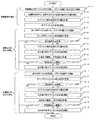
以下、プリスキャンにおいて、渦電流601の0次成分と1次成分、並びに残留磁場602に起因するRFパルス403の位相と核スピンの位相とのずれを補正する手順を説明する。図4は、本実施形態のRFパルス403の位相補正処理のフローチャートである。以下の処理は、制御部311が上記パルスシーケンスおよびプログラムに従って、各部の動作を制御し、実行する。本実施形態では、残留磁場602によるRFパルス403の位相のずれを補正し、次に、渦電流601の0次成分によるずれを補正し、最後に渦電流601の1次成分によるずれを補正する。
Hereinafter, a procedure for correcting a shift between the phase of the
まず、残留磁場602に起因するRFパルス403の位相のずれの補正を行う。上述のように、残留磁場602によって振動傾斜磁場404の形状が損なわれると、核スピンの位相と照射するサブパルス403subの位相とに差が生じる。これは、選択されたスライス面内では、Y方向の励起位置のずれとなって現れる。このY方向の励起位置のずれ量からサブパルス403sub間の位相のずれ量を算出することができる。本実施形態では、算出したずれ量を用いて、各サブパルス403subの位相を補正する。
First, the phase shift of the
なお、Z方向の振動傾斜磁場404の場合、残留磁場602の傾斜磁場強度は、Z方向に線形に発生する。従って、この残留磁場602によるY方向の励起位置のずれ量もZ方向に線形に発生する。このため、残留磁場602によるRFパルス403の位相の補正値はZ方向の位置(スライス位置)の関数となる。従って、本実施形態では、スライス位置を2箇所設定して撮影を行い、それぞれのスライス位置に応じたY方向の励起位置のずれ量を算出する。
In the case of the oscillating gradient
励起位置のずれ量は、残留磁場602に起因するものと渦電流601に起因するものがある。ここでは、残留磁場602のみの影響を抽出し、渦電流601の影響を除去する必要がある。振動傾斜磁場404の正転時と反転時とで渦電流601の極性は異なる。しかし、印加される絶対量は等しい。従って、正転時と反転時との間で渦電流601は打ち消しあうので、正転時のRFパルス間および反転時のRFパルス間では、渦電流601に起因する核スピンとRFパルス403との位相差は等しくなる。従って、図2のRFパルス403のうち、スライス傾斜磁場である振動傾斜磁場404が正転または反転のいずれかの場合のサブパルス403subのみを印加して撮影を行い、その結果得られる画像の励起プロファイルから励起位置のずれ量を算出することにより、渦電流601の影響を排除して、残留磁場602に起因するもののみを抽出することができる。以下、正転の場合のサブパルス403subのみを印加した場合を例にあげて説明する。
The amount of displacement of the excitation position may be due to the residual
ここで、ZexをZ方向の励起サイズ、YexをY方向の励起サイズ、Zをスライス位置とする。まず、正転の場合のサブパルス403subのみを印加した撮影を、励起サイズZex*Yexを一定とし、スライス位置Z=Z1に設定した場合と、Z=Z2に設定した場合との2回行なう[ステップ1−1]。なお、スライス位置Z1、Z2は、MRI装置300の仕様から、RFパルス403を構成する各サブパルス403sub間で180度以上位相がずれないスライス位置とする。
Here, Zex is an excitation size in the Z direction, Yex is an excitation size in the Y direction, and Z is a slice position. First, imaging in which only the sub-pulse 403sub is applied in the case of normal rotation is performed twice, when the excitation size Zex * Yex is constant and the slice position Z = Z1 is set, and when Z = Z2 is set [Step] 1-1]. Note that the slice positions Z1 and Z2 are slice positions whose phases are not shifted by 180 degrees or more between the sub-pulses 403sub constituting the
図5は、各スライス位置Zl、0、Z2における撮影結果と励起プロファイルのずれを説明するための図である。ここで、スライス位置Z=0は、振動傾斜磁場404において、常に傾斜磁場が0の位置である。図5(a)において、201p、200p、および202pは、それぞれ、X方向の同位置におけるY方向のラインプロファイル(励起プロファイル)である。ここでは、一例としてX=0における励起プロファイルを示す。スライス位置Z=0におけるY方向の励起位置(視野中心)をY=0とする。すなわち、スライス位置Z=0では、Y方向の励起位置のずれ量は0である。
FIG. 5 is a diagram for explaining the difference between the imaging result and the excitation profile at each slice position Zl, 0, Z2. Here, the slice position Z = 0 is a position where the gradient magnetic field is always 0 in the oscillating gradient
スライス位置Zl、Z2における撮影結果201、202の各ラインプロファイル201p、202p上で、各励起位置203、204の、視野中心からのずれ量を検出する[ステップ1−2]。これらは、それぞれのスライス位置における残留磁場602の影響による励起位置のY方向の視野中心からのずれ量である。そして、上述のように、励起位置のY方向のずれ量は、Z方向に線形であるため、例えば、図5(b)に示すように、横軸をスライス位置Z、縦軸をY方向への励起位置のずれ量としたグラフから最小二乗法で傾きαを求める等の手法により、任意のスライス位置ZにおけるY方向の励起位置のずれ量Yshift(Z)を表す式(例えば、式(1))を決定する。
Yshift(Z)=αZ (1)
On the line profiles 201p and 202p of the imaging results 201 and 202 at the slice positions Zl and Z2, the amount of deviation from the center of the visual field of each
Y shift (Z) = αZ (1)
求めたスライス位置Zにおけるずれ量Yshift(Z)を用いて、スライス位置Zにおける残留磁場602に起因するRFパルス403を構成する各サブパルス403sub間の位相のずれ量ΔPhr(Z)を算出する[ステップ1−3]。ここで、残留磁場602に起因するサブパルス403sub間の位相ずれ量ΔPhr(Z)は、式(1)で求めたずれ量Yshift(Z)を用いて次式(2)で求めることができる。
ΔPhr(Z)=−(Yshift(Z))/Δpp×360[deg] (2)
ここで、Δppは、図5に示す折り返し間隔206である。ブリップ傾斜磁場の印加量をSGz(テスラ/メートル/秒)とすると、折り返し間隔206Δppは、Δpp=1/(γSGz)と表すことができる。なお、式(2)は、振幅変調包絡線波402の関数形状により決まる。例えば、振幅変調包絡線402をsinc関数形状、RFパルス403内のサブパルス403sub数をNとすると、式(2)は以下のとおりである。
ΔPhr(Z)=−(Yshift(Z))/((N−1)×Yex/2)×360[deg]
Using the obtained shift amount Y shift (Z) at the slice position Z, a phase shift amount ΔPhr (Z) between the sub-pulses 403sub constituting the
ΔPhr (Z) = − (Y shift (Z)) / Δpp × 360 [deg] (2)
Here, Δpp is the
ΔPhr (Z) = − (Y shift (Z)) / ((N−1) × Yex / 2) × 360 [deg]
そして、ステップ1−3で求めたサブパルス403sub間の位相のずれ量ΔPhr(Z)を用いて、各サブパルス403subの位相を補正する[ステップ1−4]。すなわち、m番目のサブパルス403subの位相に対する補正値ΔPhr(Z)mは、(m−1)*ΔPhr(Z)(m=1,2,3,…,N)となる。各サブパルス403subの位相にΔPhr(Z)mを加算し、補正する。 Then, using the phase shift amount ΔPhr (Z) between the sub-pulses 403sub obtained in step 1-3, the phase of each sub-pulse 403sub is corrected [step 1-4]. That is, the correction value ΔPhr (Z) m for the phase of the mth sub-pulse 403sub is (m−1) * ΔPhr (Z) (m = 1, 2, 3,..., N). ΔPhr (Z) m is added to the phase of each sub-pulse 403sub to correct it.
残留磁場602による位相のずれの補正後、渦電流601の0次成分によるRFパルス403の位相のずれの補正を行う。上述のように、残留磁場602の影響により励起プロファイルの励起位置がY方向にずれる。その他の励起プロファイルの歪みは、渦電流601の影響によるものである。本実施形態では、図6に示すように、励起間に不要な励起として現れる。ここでは、通常どおり全てのRFパルス403を印加して撮影を行い、その結果得られる画像の励起プロファイルから、本来励起すべき位置ではない箇所で発生する励起の信号強度と、本来励起すべき位置のおける励起の信号強度の比を求め、その値からサブパルス403sub間の位相のずれ量を算出し、各サブパルス403subを補正する。
After correcting the phase shift due to the residual
具体的には、まず、図2のRFパルス403のうち、全てのサブパルス403subを印加して撮影を行う[ステップ2−1]。撮影は、励起サイズZex*Yexを一定とし、スライス位置Zを0に設定して行なう。これは、渦電流601の0次成分によるRFパルス403の位相のずれ量は、Z方向の位置によらないためである。
Specifically, first, imaging is performed by applying all the sub-pulses 403sub in the
次に、上記ステップ1−2と同様に、撮影結果のX=0におけるY方向のラインプロファイル(励起プロファイル)をとり、本来励起すべき位置における励起の信号強度と渦電流の影響による励起の信号強度との比を計算する[ステップ2−2]。 Next, as in step 1-2 above, a line profile (excitation profile) in the Y direction at X = 0 of the imaging result is taken, and the excitation signal intensity and the excitation signal due to the influence of the eddy current at the position where excitation should be originally performed. The ratio with the intensity is calculated [Step 2-2].
この時の励起プロファイルを図6に示す。渦電流の影響による励起が現れる位置は、振幅変調包絡線402の関数形状及びサブパルス403subの数により決まる。具体的には、励起は、リードアウトのN/2アーチファクトに相当するものであり、折り返し間隔206の中点YMに現れる。位置Yにおける信号強度をS(Y)とすると、本来励起すべき位置であるY=0における励起501の信号強度S(0)と、YMにおける励起502の信号強度S(YM)の比F=S(0)/S(YM)を計算する。
The excitation profile at this time is shown in FIG. The position where the excitation due to the influence of the eddy current appears is determined by the function shape of the
一例として、サブパルス403subの数をN、振幅変調包絡線402をsinc関数形状とすると、Y=Yex*(N−1)/4の位置に渦電流601の影響による励起502が現れる。この場合、本来励起すべき位置であるY=0における励起501の信号強度S(Y)と、Y=Yex*(N−1)/4における励起502の信号強度S(Y)とをそれぞれ計測し、その信号強度比F=S(0)/S(Yex*(N−1)/4)を計算する。
As an example, if the number of
次に、算出した信号強度比Fを所定の閾値と比較することにより補正の要否を判断する[ステップ2−3]。すなわち、信号強度比Fが十分大きければ、渦電流601による励起形状の歪みによる励起502は、本来励起すべき位置における励起501に影響を与えないとし、補正は不要と判断する。例えば、閾値を20とし、信号強度比Fが20以上であれば、渦電流601の0次成分による影響の補正は必要ないと判断し、後述する渦電流601の1次成分による影響の補正ステップ3−1に進む。一方、信号強度比Fが20未満の場合、ステップ2−4に進み、位相のずれ量を計算する。なお、閾値(ここでは20)は、2次元選択励起RFパルス401の使用目的により任意の値を設定可能である。
Next, the necessity of correction is determined by comparing the calculated signal strength ratio F with a predetermined threshold [step 2-3]. That is, if the signal intensity ratio F is sufficiently large, it is determined that the
信号強度比Fが20未満の場合、渦電流601の0次成分に起因するサブパルス403sub間の位相のずれ量ΔPhe0を計算する[ステップ2−4]。サブパルス403sub間の位相のずれ量の絶対値ΔPhe0は、信号強度比Fを用いて次式(3)で表される。
ΔPhe0=arctan(F)/π×360[deg] (3)
When the signal intensity ratio F is less than 20, the phase shift amount ΔPhe0 between the subpulses 403sub due to the 0th-order component of the
ΔPhe0 = arctan (F) / π × 360 [deg] (3)
ΔPhe0は、サブパルス403sub間の位相のずれ量である。従って、m番目のサブパルス403subの位相に対する補正値ΔPhe0mは、(m−1)番目のサブパルス403subのずれ量にΔPhe0を加算したものとなる。ここで、渦電流601の0次成分による位相のずれ量ΔPhe0は、図3に示すように渦電流601が正負交互に発生するため、サブパルス403sub毎に正負の値が交互に現れる。従って、例えば、正負の順に現れるとすると、2番目のサブパルス403subの1番目のサブパルス403subからの位相のずれ量は、ΔPhe0、3番目のサブパルス403subの1番目からのずれ量は、ΔPhe0(2番目のずれ量)+(―ΔPhe0)=0、4番目のサブパルス403subの1番目からのずれ量は、0(3番目のずれ量)+ΔPhe0=ΔPhe0、5番目のサブパルス403subの1番目からのずれ量は、ΔPhe0(4番目のずれ量)+(―ΔPhe0)=0・・・となる。
ΔPhe0 is the amount of phase shift between the sub-pulses 403sub. Therefore, the correction value ΔPhe0m for the phase of the mth subpulse 403sub is obtained by adding ΔPhe0 to the amount of deviation of the (m−1) th subpulse 403sub. Here, the phase shift amount ΔPhe0 due to the zeroth-order component of the
ここでは、ΔPhe0が正負いずれの順に発生するか不明であるため、まず、正の値を補正値として、偶数番目(第2、4番目・・・)のサブパルス403subの位相に加算する。[ステップ2−5]。ここでは、両サブパルス403subに同じ補正値ΔPhe0を加算する。その後、再びステップ2−1と同条件で撮影を行い、その励起プロファイルの歪みから、ステップ2−2〜2−3と同様に信号強度比Fを求める[ステップ2−6]。 Here, since it is unknown whether ΔPhe0 occurs in the order of positive or negative, first, a positive value is added as a correction value to the phase of the even-numbered (second, fourth,...) Sub-pulse 403sub. [Step 2-5]. Here, the same correction value ΔPhe0 is added to both sub-pulses 403sub. Thereafter, imaging is performed again under the same conditions as in Step 2-1, and the signal intensity ratio F is obtained from the distortion of the excitation profile in the same manner as in Steps 2-2 to 2-3 [Step 2-6].
そして、信号強度比Fを閾値と比較し、補正に採用した値の可否を判断する[ステップ2−7]。本実施形態では、例えば、信号強度比Fが20以上となれば、ステップ2−5で採用した値を補正値とする。なお、ここでの判断基準となる20は、上記同様、2次元選択励起RFパルス401の使用目的により任意の値を設定可能である。
Then, the signal intensity ratio F is compared with a threshold value to determine whether the value adopted for the correction is acceptable [step 2-7]. In the present embodiment, for example, if the signal intensity ratio F is 20 or more, the value adopted in step 2-5 is set as the correction value. Note that 20 as the determination criterion can be set to an arbitrary value depending on the purpose of use of the two-dimensional selective
一方、20未満ならば、ステップ2−5で用いなかった負の値を補正値として、偶数番目(第2、4番目・・・)のサブパルス403subの位相に加算する[ステップ2−8]。以上により、渦電流601の0次成分によるRFパルス403の位相のずれの補正を行う。なお、本実施形態では、偶数番目のサブパルス403subの位相に加算することにより、偶数番目のサブパルス403subの位相を奇数番目の位相に一致させるよう補正を行っている。しかし、逆に、奇数番目のサブパルス403subの位相から補正値を減算することにより、奇数番目のサブパルス403subの位相を偶数番目に一致させても良い。また、式(3)で算出したΔPhe0の正負の値は、どちらを先に採用してもよい。
On the other hand, if it is less than 20, the negative value not used in step 2-5 is added as a correction value to the phase of the even-numbered (second, fourth,...) Sub-pulse 403sub [step 2-8]. As described above, the phase shift of the
渦電流601の0次成分の補正後、渦電流601の1次成分によるRFパルス403の位相のずれの補正を行う。手順は、0次成分の補正と基本的に同様である。しかし、渦電流601の1次成分は、さらにZ方向に線形に変化する。このため、渦電流601の1次成分によるRFパルス403の位相の補正値はZ方向の位置(スライス位置)の関数となる。
After correcting the zero-order component of the
具体的には、まず、図2のRFパルス403のうち、全てのサブパルス403subを印加して撮影を行う[ステップ3−1]。撮影は、励起サイズZex*Yexを一定として行う。ただし、1次成分の補正時は、スライス位置ZをZ3(≠0)に設定して行なう。なお、スライス位置Z3は、MRI装置300の仕様とZexとから、RFパルス403を構成するサブパルス403sub間で180度以上位相がずれないスライス位置とする。
Specifically, first, imaging is performed by applying all the sub-pulses 403sub in the
次に、ステップ2−2同様、撮影結果の励起プロファイルをとり、渦電流601の影響による位置Y=YMにおける励起502の信号強度S(YM)と、本来励起すべき位置であるY=0における励起501の信号強度S(0)とを計測し、両者の信号強度比Fを計算する[ステップ3−2]。ここでは、励起502は、YM=Yex*(N−1)/4の位置に発生するものとする。そして、信号強度比Fを所定の閾値と比較し、許容範囲であるか否かを判別する[ステップ3−3]。ここでは、一例として、閾値を60とし、信号強度比Fが60以上であれば、本来励起すべき位置における励起に影響を与えないものとし、補正は不要と判断し、処理を終了する。なお、閾値(ここでは60)は、2次元選択励起RFパルス401の使用目的により任意の値を設定可能である。
Next, as in step 2-2, the excitation profile of the imaging result is taken, and the signal intensity S (Y M ) of the
一方、信号強度比Fが60未満の場合、渦電流601の1次成分に起因するサブパルス403sub間の位相のずれ量を計算する[ステップ3−4]。ここで、スライス位置Zにおけるサブパルス403sub間の位相ずれ量の絶対値ΔPhe1(Z)は、信号強度比Fを用いて、次式(4)で求められる。
ΔPhe1(Z)=arctan(F)/π×Z/Z3×360[deg] (4)
On the other hand, when the signal intensity ratio F is less than 60, the amount of phase shift between the sub-pulses 403sub due to the primary component of the
ΔPhe1 (Z) = arctan (F) / π × Z / Z3 × 360 [deg] (4)
0次成分の補正時同様、ずれ量として正負2つの値が得られる。いずれを採用すべきかを0次成分の補正時と同様の手順で決定する。ここでは、まず、式(4)で求めた値のうち、正の値を偶数番目のサブパルス403subの位相に加算する[ステップ3−5]。その後、再びステップ3−1と同条件で撮影を行い、その励起プロファイルの歪みから、ステップ3−2〜3−3と同様に信号強度比Fを求める[ステップ3−6]。 Similar to the correction of the 0th-order component, two positive and negative values are obtained as the deviation amount. Which one should be adopted is determined by the same procedure as that for correcting the zeroth-order component. Here, first, a positive value among the values obtained by Expression (4) is added to the phase of the even-numbered sub-pulse 403sub [step 3-5]. Thereafter, imaging is performed again under the same conditions as in step 3-1, and the signal intensity ratio F is obtained from the distortion of the excitation profile in the same manner as in steps 3-2 to 3-3 [step 3-6].
そして、0次成分同様、信号強度比Fを所定の閾値と比較し、補正に採用した値の可否を判断する[ステップ3−7]。すなわち、ここでは、例えば、信号強度比Fが60以上か否かを判別し、60以上であれば、ステップ3−5で採用した値を補正値とする。一方、60未満ならば、ステップ305で用いなかった負の値を補正値として、偶数番目のサブパルス403subの位相にそれぞれ加算する[ステップ3−8]。以上により、渦電流601の1次成分によるRFパルス403の位相のずれの補正を行う。なお、ここでも、0次成分と同様に、奇数番目のサブパルス403subの位相を偶数番目に一致させるよう構成してもよい。また、補正値は、正負どちらを先に採用してもよい。
Then, like the 0th-order component, the signal intensity ratio F is compared with a predetermined threshold value to determine whether the value adopted for the correction is acceptable [step 3-7]. That is, here, for example, it is determined whether or not the signal intensity ratio F is 60 or more, and if it is 60 or more, the value adopted in step 3-5 is set as the correction value. On the other hand, if it is less than 60, a negative value not used in
以上、本実施形態によれば、振動傾斜磁場と共に複数のRFパルスを印加するパルスシーケンスにおいて、振動傾斜磁場による残留磁場および渦電流に起因する核スピンの位相のRFパルスの位相からのずれを、RFパルスを構成する個々のサブパルスの位相を制御することにより補正する。サブパルスの位相と核スピンの位相とのずれは、撮影結果の励起プロファイルの励起位置、歪みから算出する。 As described above, according to the present embodiment, in the pulse sequence in which a plurality of RF pulses are applied together with the oscillating gradient magnetic field, the deviation of the phase of the nuclear spin caused by the residual magnetic field and eddy current due to the oscillating gradient magnetic field from the phase of the RF pulse is Correction is performed by controlling the phase of the individual sub-pulses constituting the RF pulse. The shift between the phase of the sub pulse and the phase of the nuclear spin is calculated from the excitation position and distortion of the excitation profile of the imaging result.
本実施形態によれば、核スピンの位相のRFパルスの位相からのずれについて、渦電流および残留磁場という2つの原因に対して1つのパラメータで対策ができる。また、装置による磁場の歪みも吸収でき、メンテナンスの手間がかからない。さらに、本実施形態の手法によれば、磁場を調整することにより位相を制御する手法に比べ、位相の微調整は容易である。従って、本実施形態によれば、高精度かつ容易に補正が可能であり、残留磁場および渦電流の影響を高精度かつ容易に除去でき、良好な空間選択能を得ることができる。 According to the present embodiment, it is possible to take measures against the two causes of the eddy current and the residual magnetic field with respect to the deviation of the phase of the nuclear spin from the RF pulse. Moreover, the distortion of the magnetic field by an apparatus can also be absorbed and a maintenance labor is not required. Furthermore, according to the method of the present embodiment, fine adjustment of the phase is easier than the method of controlling the phase by adjusting the magnetic field. Therefore, according to the present embodiment, the correction can be performed with high accuracy and easily, the influence of the residual magnetic field and the eddy current can be easily removed with high accuracy, and a good space selection ability can be obtained.
<<第二の実施形態>>
次に、本発明を適用する第二の実施形態について説明する。第一の実施形態では、プリスキャンの位相補正処理において、RFパルスの位相のずれ量を撮影画像の励起プロファイルから検出する。しかし、本実施形態では、受信信号(エコー信号)から位相のずれ量を得る。なお、本実施形態のMRI装置300は、基本的に第一の実施形態と同様であるため、ここでは、詳細は説明しない。以下、第一の実施形態と異なる構成に主眼をおいて説明する。また、説明において第一の実施形態と同じものについては同じ符号を使用する。
<< Second Embodiment >>
Next, a second embodiment to which the present invention is applied will be described. In the first embodiment, the phase shift amount of the RF pulse is detected from the excitation profile of the captured image in the pre-scan phase correction process. However, in this embodiment, the phase shift amount is obtained from the received signal (echo signal). Note that the MRI apparatus 300 of the present embodiment is basically the same as that of the first embodiment, and therefore details thereof will not be described here. Hereinafter, a description will be given focusing on the configuration different from the first embodiment. In the description, the same reference numerals are used for the same components as those in the first embodiment.
計測されるエコー信号は、実部(Re)と虚部(Im)とから構成される。時刻tにおけるエコー信号F(t)の位相φ(t)はtan−1(Im(F(t)))/(Re(F(t)))と表される。tan−1は、アークタンジェント関数、Im(X)は複素数Xの虚部、Re(X)は複素数Xの実部を表す。 The echo signal to be measured is composed of a real part (Re) and an imaginary part (Im). The phase φ (t) of the echo signal F (t) at time t is expressed as tan −1 (Im (F (t))) / (Re (F (t))). tan −1 represents an arctangent function, Im (X) represents an imaginary part of the complex number X, and Re (X) represents a real part of the complex number X.
図7は、本実施形態のRFパルス403の位相補正処理のフローチャートである。本実施形態においても、第一の実施形態と同様、残留磁場602、渦電流601の0次成分、渦電流601の1次成分により発生する核スピンの位相とRFパルス403の位相とのずれを、RFパルス403側の位相を制御することにより補正する。また、これらの処理は、制御部311が上記パルスシーケンスおよびプログラムに従って、各部の動作を制御し、実行する。
FIG. 7 is a flowchart of the phase correction process of the
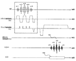
図8は、本実施形態で用いるパルスシーケンスである。本実施形態では、第一の実施形態と同様、2次元選択励起RFパルス401を印加し、エコー信号801を取得する。ただし、本実施形態では、サブパルス403subごとにエコー信号801を分離可能なようにブリップ傾斜磁場方向に読み出し傾斜磁場804を印加する。なお、ここでは、エコー信号801の取得タイミングを制御し、サブパルス403sub毎にそれぞれ別個に取得(A/D)802する場合を例にあげて説明する。本実施形態の他の構成は、第一の実施形態のパルスシーケンスと同様である。なお、以下においては、一例として、サブパルス403subが5個の場合を例にあげて説明する。もちろん、サブパルス403subの数はこれに限られない。
FIG. 8 shows a pulse sequence used in this embodiment. In the present embodiment, as in the first embodiment, the two-dimensional selective
本実施形態では、まず、Z=0とZ=Z4(≠0)とスライス位置を2箇所決定し、それぞれのスライス位置に設定して図8に示すパルスシーケンスを実行してエコー信号801を取得し、それぞれのスライス位置の各エコー信号のピーク時の位相(φ(t)の最大値、以下、ピーク位相と呼ぶ。)を用いて、残留磁場602による位相のずれ、渦電流601の0次成分による位相のずれ、渦電流601の1次成分による位相のずれの順に補正を行う。
In this embodiment, first, Z = 0 and Z = Z4 (≠ 0) and two slice positions are determined, set to the respective slice positions, the pulse sequence shown in FIG. 8 is executed, and the
まず、全てのサブパルス403subを印加してエコー信号801の取得(撮影)を行う。ここでは、励起サイズZex*Yexを一定とし、スライス位置Zを、Z=0およびZ=Z4の2箇所に設定してそれぞれ図8に示すパルスシーケンスを実行してエコー信号801を取得する[ステップ4−1]。なお、スライス位置Z4は、MRI装置300の仕様から、RFパルス403を構成する各サブパルス403sub間で180度以上位相がずれないスライス位置とする。
First, all the sub-pulses 403sub are applied to acquire (photograph) the
次に、サブパルス403sub毎に受診するエコー信号801のピークを、それぞれのサンプリングタイミング(A/D)の中心に合致させる[ステップ4−2]。ここでは、受信したエコー信号801をフーリエ変換(FT)し、FT結果の位相マップから判別する。エコー信号801がA/Dの中心で受信できていない場合は、エコー信号801のピークがA/Dの中心になるように補正する。補正は公知の手法(例えば、特許文献3または非特許文献3参照。)で行う。なお、各スライス面で取得したそれぞれ5つのエコー信号801からピーク位相を検出し、それぞれ、スライス面および対応するサブパルス403subの照射順に対応づけて記憶しておく。
Next, the peak of the
次に、残留磁場602に起因するRFパルス403の位相のずれの補正を行う[ステップ4−3]。残留磁場602は、Z方向に線形に発生し、時間がたつにつれて影響(ずれ)は大きくなる。残留磁場602による影響のみを抽出するため、ここでは、スライス位置をZ4に設定して取得した5つのエコー信号801のうち、振動傾斜磁場404が正転または反転のいずれかの場合のサブパルス403subのみのエコー信号801のピーク位相のずれ量を用いて、サブパルス403sub間の位相のずれを算出する。ここでは、一例として、奇数番目のサブパルス403sub(すなわち、第1、第3、第5)によるエコー信号801のピーク位相を用いる場合を例にあげて説明する。
Next, the phase shift of the
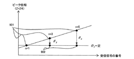
まず、n番目のエコー信号801のピーク位相の第1番目のエコー信号801のピーク位相からのずれ量θnを求める。上述のように、ピーク位相のずれ量は時間にほぼ線形に変化するため、例えば、図9に示すように、横軸を受信したエコー信号801の番号n、縦軸をピーク位相として奇数番目のエコー信号801のピーク位相901をプロットしたグラフから最小二乗法で傾きを求める等の手法により、n番目のエコー信号801のピーク位相のずれ量θn=βn+γを求める(β、γは定数)。
First, the shift amount θn of the peak phase of the n-
そして、得られたずれ量θnを用いて、スライス位置Z4における残留磁場602に起因するRFパルス403を構成する各サブパルス403sub間の位相のずれ量ΔPhr(Z)を算出する。位相のずれ量ΔPhr(Z)は、以下の式(5)で表される。
ΔPhr(Z)=β[deg]×Z/Z4 (5)
Then, using the obtained deviation amount θn, a phase deviation amount ΔPhr (Z) between the sub-pulses 403sub constituting the
ΔPhr (Z) = β [deg] × Z / Z4 (5)
そして、式(5)で求めたサブパルス403sub間の位相のずれ量ΔPhr(Z)を用いて、各サブパルス403subの位相を補正する。ここでは、第一の実施形態と同様に、m番目のサブパルス403subの位相に対する補正値ΔPhr(Z)mは、(m−1)×ΔPhr(Z)(m=1,2,3,…,5)となる。各サブパルス403subの位相にΔPhr(Z)mを加算し、補正する。 Then, the phase shift amount ΔPhr (Z) between the sub-pulses 403sub obtained by the equation (5) is used to correct the phase of each sub-pulse 403sub. Here, as in the first embodiment, the correction value ΔPhr (Z) m for the phase of the mth sub-pulse 403sub is (m−1) × ΔPhr (Z) (m = 1, 2, 3,... 5). ΔPhr (Z) m is added to the phase of each sub-pulse 403sub to correct it.
このように各サブパルス403subの位相を補正することにより、得られる奇数番目のエコー信号801のピーク位相は、902のように一定となる。なお、本実施形態では、奇数番目のサブパルス403subによるエコー信号801を用いてピーク位相のずれを求めている。しかし、偶数番目のサブパルス403subによるエコー信号801を用いて求めてもよい。
By correcting the phase of each sub-pulse 403 sub in this way, the peak phase of the obtained odd-numbered
次に、渦電流601の0次成分によるRFパルス403の位相のずれの補正を行う[ステップ4−4]。ここでは、スライス面Z=0と設定して取得した5つのエコー信号801全てのピーク位相を用いて、渦電流601の0次成分に起因するRFパルス403を構成する各サブパルス403sub間の位相のずれ量を求める。スライス面Z=0と設定して得られたエコー信号801を用いるのは、スライス面Z=0では、残留磁場602の影響を受けない一方で、渦電流601の0次成分によるRFパルス403の位相のずれ量は、Z方向の位置によらないためである。
Next, the phase shift of the
まず、スライス面Z=0と設定して取得した各エコー信号801のピーク位相の、第1番目のエコー信号801のピーク位相とのずれ量θe0を求める。ここでは、横軸を受信したエコー信号801の番号n、縦軸をピーク位相として各エコー信号801のピーク位相をプロットすると、図10に示すように、奇数番目および偶数番目のエコー信号801のピーク位相は、それぞれ一定となる。これは、渦電流601の0次成分による影響が、振動傾斜磁場404正転時および反転時に同等に現れ、打ち消し合い、累積しないためである。そして、奇数番目のエコー信号801のピーク位相と偶数番目のエコー信号801のピーク位相との差をピーク位相のずれ量θe0として検出する。
First, a shift amount θe0 between the peak phase of each echo signal 801 acquired by setting the slice plane Z = 0 and the peak phase of the
そして、渦電流601の0次成分に起因するRFパルス403を構成する各サブパルス403sub間の位相のずれ量ΔPhe0には、エコー信号801のピーク位相のずれ量がそのまま現れる。従って、得られたピーク位相のずれ量θe0を用いて式(6)で表される。
ΔPhe0=θe0[deg] (6)
The peak phase shift amount of the
ΔPhe0 = θe0 [deg] (6)
そして、得られた位相のずれ量ΔPhe0を偶数番目のサブパルス403subの位相に加算する。または、逆に奇数番目のサブパルス403subの位相から減算する。例えば、偶数番目のサブパルス403subの位相に加算して補正した場合、受信した各エコー信号801のピーク位相は、図10の1001から1002になる。従って、サブパルス403sub間で位相が揃うので、各エコー信号801間のピーク位相が揃う。これにより、RFパルス403の、渦電流601の0次成分に起因する位相のずれが補正される。
Then, the obtained phase shift amount ΔPhe0 is added to the phase of the even-numbered sub-pulse 403sub. Or, conversely, the phase is subtracted from the phase of the odd-numbered sub-pulse 403sub. For example, when correction is performed by adding to the phase of the even-numbered sub-pulse 403 sub, the peak phase of each received
次に、渦電流601の1次成分によるRFパルス403の位相のずれの補正を行う[ステップ4−5]。ここでは、スライス面Z=Z4に設定して取得した5つのエコー信号801全てのピーク位相を用いて、渦電流601の1次成分に起因するRFパルス403を構成する各サブパルス403sub間の位相のずれ量を求める。スライス面Z=Z4では、残留磁場602に起因するものと、渦電流601の0次成分に起因するものと、同1次成分に起因するものとを加算した位相のずれが発生する。従って、渦電流601の1次成分に起因する位相のずれは、残留磁場602に起因するものと渦電流601の0次成分に起因するものとを除去することにより得られる。
Next, the phase shift of the
ここでは、横軸を受信したエコー信号801の番号n、縦軸をピーク位相として各エコー信号801のピーク位相をプロットすると、図11に示すようになる。上述のように、各ピーク位相には、残留磁場602に起因するものと渦電流601の0次成分に起因するものとが含まれる。まず、これらを差し引く。すなわち、各ピーク位相から、それぞれ、ステップ4−3で求めた、残留磁場602によるn番目のエコー信号801のピーク位相のずれ量θnおよび、ステップ4−4で求めた、渦電流601の0次成分によるピーク位相のずれ量θe0を差し引く。
Here, when the peak phase of each
そして、両ずれ量を差し引いた結果得られたエコー信号801のピーク位相のずれ量θe1が渦電流601の1次成分によるピーク位相のずれ量である。ここで、本実施形態では、残留磁場602によるピーク位相のずれ量を、奇数番目のエコー信号801で求めているため、このとき、ずれ量が発生するのは、偶数番目のエコー信号801のピーク位相1101である。
The peak phase shift amount θe1 of the
渦電流601の1次成分は、上述のようにZ方向に線形に変化するため、渦電流601の1次成分に起因するRFパルス403を構成する各サブパルス403sub間の位相のずれ量ΔPhe1(Z)はスライス面Zの関数となる。また、エコー信号801のピーク位相のずれ量は、各サブパルス403sub間の位相のずれ量をそのまま反映したものである。従って、位相のずれ量ΔPhe1(Z)は、Zおよび得られたエコー信号801のピーク位相のずれ量θe1を用いて式(7)で表される。
ΔPhe1(Z)=θe1[deg]×Z/Z4 (7)
Since the primary component of the eddy current 601 changes linearly in the Z direction as described above, the phase shift amount ΔPhe1 (Z ) Is a function of the slice plane Z. Further, the peak phase shift amount of the
ΔPhe1 (Z) = θe1 [deg] × Z / Z4 (7)
得られた位相のずれ量ΔPhe1(Z)を偶数番目のサブパルス403subの位相に加算する。または、逆に奇数番目のサブパルス403subの位相から減算する。これにより、例えば、偶数番目のサブパルス403subの位相に加算して補正した場合、受信した各エコー信号801のピーク位相は、図11の1101から1102になる。従って、各エコー信号801間でピーク位相が一定となり、RFパルス403の、渦電流601の1次成分に起因する位相のずれの補正ができる
The obtained phase shift amount ΔPhe1 (Z) is added to the phase of the even-numbered sub-pulse 403sub. Or, conversely, the phase is subtracted from the phase of the odd-numbered sub-pulse 403sub. Accordingly, for example, when correction is performed by adding to the phase of the even-numbered sub-pulse 403 sub, the peak phase of each received
以上のように、本実施形態によれば、振動傾斜磁場と共に複数のRFパルスを印加するパルスシーケンスにおいて、振動傾斜磁場による残留磁場および渦電流に起因する核スピンの位相のRFパルスの位相からのずれを、RFパルスを構成する個々のサブパルスの位相を制御することにより補正する。サブパルスの位相と核スピンの位相とのずれは、各サブパルスに対応して受信するエコー信号のピーク位相のずれから算出する。従って、第一の実施形態と同様に、高精度かつ容易に補正が可能であり、残留磁場および渦電流の影響を高精度かつ容易に除去でき、良好な空間選択能を得ることができる。 As described above, according to the present embodiment, in a pulse sequence in which a plurality of RF pulses are applied together with an oscillating gradient magnetic field, the phase of the nuclear spin caused by the residual magnetic field and eddy current due to the oscillating gradient magnetic field is different from the phase of the RF pulse. Deviations are corrected by controlling the phase of the individual subpulses that make up the RF pulse. The shift between the phase of the subpulse and the phase of the nuclear spin is calculated from the shift in the peak phase of the echo signal received corresponding to each subpulse. Therefore, as in the first embodiment, correction can be performed with high accuracy and easily, the influence of the residual magnetic field and eddy current can be removed with high accuracy and easily, and good spatial selectivity can be obtained.
さらに、本実施形態によれば、プリスキャンとしての信号取得が2回で済み、また、画像を再構成する必要がないため、全体の撮像にかかる時間を短縮することができる。 Furthermore, according to the present embodiment, signal acquisition as pre-scanning is only required twice, and it is not necessary to reconstruct the image, so that it is possible to reduce the time taken for the entire imaging.
なお、本実施形態では、各サブパルス403subによるエコー信号802を、それぞれ個別にサンプリング(A/D)している。しかし、本実施形態は、この構成に限られない。エコー信号801をサブパルス毎に分離可能であればよい。例えば、図12は、本実施形態のパルスシーケンスの別例である。本図に示すように、全てのサブパルス403subによるエコー信号1201を、一度にサンプリング(A/D)1202するよう構成してもよい。この場合、サンプリング後の信号から、照射したサブパルス403subに対応するピークを検出し、それぞれのピーク位相とする。なお、本構成では、受信するエコー信号1201のピークとサンプリングタイミング(A/D)の中心とを一致させるための補正は、1回でよい。従って、全体の処理時間は上記の実施形態に比べて短くなる。
In this embodiment, the
<<第三の実施形態>>
次に、本発明を適用する第三の実施形態について説明する。上記各実施形態では、任意の2次元領域を選択的に励起する2次元選択励起RFパルスを印加する場合を例にあげて説明した。本実施形態では、2次元選択励起RFパルスの代わりに特定種のプロトンのみを励起する空間的周波数選択励起RFパルスを印加する。本実施形態のMRI装置は、上記各実施形態のものと基本的に同様であるため、ここでは説明しない。以下、上記各実施形態と異なる構成に主眼をおいて説明する。
<< Third Embodiment >>
Next, a third embodiment to which the present invention is applied will be described. In each of the above embodiments, the case where a two-dimensional selective excitation RF pulse for selectively exciting an arbitrary two-dimensional region is applied has been described as an example. In this embodiment, a spatial frequency selective excitation RF pulse that excites only a specific type of proton is applied instead of the two-dimensional selective excitation RF pulse. The MRI apparatus of this embodiment is basically the same as that of each of the above embodiments, and will not be described here. Hereinafter, a description will be given focusing on the configuration different from the above embodiments.
本実施形態に用いる空間的周波数選択励起RFパルス1402を図13に示す。本図に示すように、本実施形態の空間的周波数選択励起RFパルス1402は、複数のRFパルス1403と、振動傾斜磁場1404とを同時に印加することにより、撮影対象となるスライス面で、特定種のプロトンを選択的に励起し、対応する周波数帯のエコー信号を収集する。周波数選択は、RFパルス1403の振幅変調包絡線の形状と、パルス間時間τ1401とにより定まる。パルス間時間τ1401は、以下の式(8)により求めることができる。
τ=1/(γ×δ×B0)/2 (8)
ここで、γは磁気回転比、δは水〜脂肪のケミカルシフト差、B0は静磁場強度である。例えば、δ=3.5ppm、γ=42.57×10⁶(Hz/T)、B0=1.5(T)の場合、
τ=1/(42.57×106×3.5×1.5)/2
=2.24(ms)である。
FIG. 13 shows a spatial frequency selective
τ = 1 / (γ × δ × B 0 ) / 2 (8)
Here, γ is the gyromagnetic ratio, δ is the chemical shift difference between water and fat, and B 0 is the static magnetic field strength. For example, when δ = 3.5 ppm, γ = 42.57 × 10 6 (Hz / T), B 0 = 1.5 (T),
τ = 1 / (42.57 × 10 6 × 3.5 × 1.5) / 2
= 2.24 (ms).
本実施形態で収集したエコー信号をフーリエ変換して得たスペクトル信号の分布を図14に示す。本図において、横軸は周波数、縦軸は信号強度である。また、太線は、装置歪みよりずれたスペクトルを、細線は、望ましいスペクトルを表す。本実施形態の残留磁場に起因するRFパルス1403の位相のずれの補正および渦電流に起因する位相のずれの補正の手順は、基本的に第一の実施形態と同様である。ただし、RFパルス1403の位相のずれ量は、周波数方向に対する励起強度の変化を計測することにより検出する。
FIG. 14 shows the distribution of spectral signals obtained by Fourier transforming the echo signals collected in this embodiment. In this figure, the horizontal axis represents frequency and the vertical axis represents signal intensity. A thick line represents a spectrum shifted from the apparatus distortion, and a thin line represents a desirable spectrum. The procedure for correcting the phase shift of the
残留磁場602に起因するRFパルス1403の位相のずれ量は、特定種のプロトンのスペクトル信号の信号強度のピーク位置の周波数方向の変位を計測することにより得る。これは、ピーク位置は、残留磁場602により、振動傾斜磁場404の形状が損なわれるため、変位する。例えば、第一の実施形態と同様に、2つのスライス位置Z1,Z2における水の信号強度から、任意のスライス位置Zにおける周波数方向の信号強度のピーク位置の変位を計測する。そしてその変位量から、各サブパルス403sub間の位相のずれ量を算出する。変位量Wshift(Z)がWshift(Z)=αZと表される場合、各サブパルス403sub間の位相のずれ量ΔPhr(Z)は、第一の実施形態の式(2)を用いて計算できる。ただし、ここでは、Yshift(Z)をWshift(Z)である。そして、m番目のサブパルスの403subに、(m−1)*ΔPhr(Z)を加算し、補正する。
The amount of phase shift of the
また、本実施形態では、渦電流601の0次成分に起因するRFパルス1403の位相のずれ量を算出する際の信号強度比Fの計算を、異なるプロトンのスペクトル信号の信号強度間で計算する。渦電流601の0次成分に起因するRFパルス1403の位相のずれ量を算出する場合、第一の実施形態と同様に、まず、残留磁場602の影響を受けないスライス面(Z=0)に設定してパルスシーケンスを実行する。そして、得られた結果から、例えば、水プロトンの信号強度1301と、脂肪プロトンの信号強度1302との信号強度比Fを求める。信号強度比Fが所定の閾値以下であれば、第一の実施形態と同様に、以下の式(3)により、各サブパルス403sub間の位相のずれ量±ΔPhe0を算出し、第一の実施形態と同様の手順で補正を行う。
In the present embodiment, the calculation of the signal intensity ratio F when calculating the phase shift amount of the
また、渦電流601の1次成分に起因するRFパルス1403の位相のずれ量は、第一の実施形態と同様にスライス位置をZ=Z3に設定してパルスシーケンスを行い、0次成分の場合と同様に、異なるプロトンによる信号強度間で信号強度比Fを求める。そして、必要に応じて第一の実施形態と同様の手順で、式(4)により、各サブパルス1403sub間の位相のずれ量±ΔPhe1(Z)を算出し、第一の実施形態と同様の手順で補正を行う。
Further, as for the phase shift amount of the
以上のように、本実施形態によれば、振動傾斜磁場と共に複数のRFパルスを印加するパルスシーケンスを用いる空間的周波数選択励起法において、残留磁場と渦電流に起因する核スピンの位相のRFパルス1403の位相からのずれを、RFパルスを構成する個々のサブパルスの位相を制御することにより補正する。本実施形態では、サブパルスの位相と核スピンの位相とのずれは、特定種のプロトンのスペクトル信号の周波数のずれおよび強度から算出する。従って、上記各実施形態同様、高精度かつ容易に補正が可能であり、残留磁場および渦電流の影響を高精度かつ容易に除去でき、良好な周波数選択能を得ることができる。 As described above, according to the present embodiment, in the spatial frequency selective excitation method using a pulse sequence in which a plurality of RF pulses are applied together with an oscillating gradient magnetic field, an RF pulse having a phase of a nuclear spin caused by a residual magnetic field and an eddy current The deviation from the phase of 1403 is corrected by controlling the phase of each sub-pulse constituting the RF pulse. In this embodiment, the shift between the phase of the sub-pulse and the phase of the nuclear spin is calculated from the frequency shift and intensity of the spectrum signal of a specific type of proton. Therefore, as in the above embodiments, the correction can be performed with high accuracy and easily, the influence of the residual magnetic field and the eddy current can be easily removed with high accuracy, and good frequency selectivity can be obtained.
上記各実施形態では、MRI装置300が備える静磁場を発生する磁石302は、永久磁石である場合を念頭において説明した。例えば、静磁場を発生する磁石302として残留磁場の発生が少ない超伝導磁石を備えるMRl装置300の場合は、上述の残留磁場に起因する位相のずれの補正の手順を省いてもよい。これにより、全補正に要する時間をさらに短縮することができる。
In the above embodiments, the case where the
なお、上記各実施形態のプリスキャンによるRFパルスの位相の補正は、残留磁場、渦電流の影響の大きさに応じ、撮影ごとに行ってもよいし、また、補正値をメモリ等に格納し、複数回の撮影に同じ補正値を用いてもよい。 The correction of the phase of the RF pulse by the pre-scan in each of the above embodiments may be performed for each imaging depending on the magnitude of the influence of the residual magnetic field and eddy current, and the correction value is stored in a memory or the like. The same correction value may be used for a plurality of shootings.
300:MRI装置、301:被検体、302:磁石、303:傾斜磁場コイル、304:RFコイル、305:RFプローブ、306:信号検出部、307:信号処理部、308:表示部、309:傾斜磁場電源、310:RF送信部、311:制御部、312:ベッド、313:画像処理部、 300: MRI apparatus, 301: subject, 302: magnet, 303: gradient magnetic field coil, 304: RF coil, 305: RF probe, 306: signal detection unit, 307: signal processing unit, 308: display unit, 309: gradient Magnetic field power supply, 310: RF transmission unit, 311: control unit, 312: bed, 313: image processing unit,
Claims (6)
前記検査対象に照射する高周波磁場パルスを発生する高周波磁場発生手段と、
前記傾斜磁場の極性を複数回反転させる振動傾斜磁場の極性反転毎に前記高周波磁場パルスを照射し、2次元の空間選択励起するように前記傾斜磁場発生手段および前記高周波磁場発生手段の駆動を制御する制御手段と、
前記振動傾斜磁場による残留磁場および渦電流による、励起する核スピンの位相と前記高周波磁場パルスの位相とのずれを、前記高周波磁場パルスの位相を補正することにより調整する補正手段と、
を備えることを特徴とする磁気共鳴イメージング装置。 A gradient magnetic field generating means for generating a gradient magnetic field in three orthogonal directions to be applied to an inspection object placed in a static magnetic field;
A high-frequency magnetic field generating means for generating a high-frequency magnetic field pulse for irradiating the inspection object;
The driving of the said high-frequency magnetic field pulse to the polarity reversal every multiple oscillating gradient magnetic field Ru by inverting the polarity of the gradient magnetic field irradiated with the two-dimensional of the gradient magnetic field generating means so as to spatially selective excitation and the high-frequency magnetic field generating means Control means for controlling;
Due to the residual magnetic field and eddy currents due to previous SL oscillating gradient magnetic field, and correcting means for adjusting by the deviation between the phase of the nuclear spins of phase with the radio frequency magnetic field pulses to excitation, to correct the phase of the radio frequency magnetic field pulses,
A magnetic resonance imaging apparatus comprising:
前記検査対象に照射する高周波磁場パルスを発生する高周波磁場発生手段と、
前記傾斜磁場の極性を複数回反転させる振動傾斜磁場の極性反転毎に前記高周波磁場パルスを照射し、2次元の空間的周波数選択励起するように前記傾斜磁場発生手段および前記高周波磁場発生手段の駆動を制御する制御手段と、
前記振動傾斜磁場による残留磁場および渦電流による、励起する核スピンの位相と前記高周波磁場パルスの位相とのずれを、前記高周波磁場パルスの位相を補正することにより調整する補正手段と、
を備えることを特徴とする磁気共鳴イメージング装置。 A gradient magnetic field generating means for generating a gradient magnetic field in three orthogonal directions to be applied to an inspection object placed in a static magnetic field;
A high-frequency magnetic field generating means for generating a high-frequency magnetic field pulse for irradiating the inspection object;
Wherein refers to the high-frequency magnetic field pulse to the polarity reversal every multiple oscillating gradient magnetic field Ru by inverting the polarity of the gradient magnetic field irradiation, 2D of the gradient magnetic field generating means so as to spatially frequency selective excitation and the high-frequency magnetic field generating means Control means for controlling the driving of
Due to the residual magnetic field and eddy currents due to previous SL oscillating gradient magnetic field, and correcting means for adjusting by the deviation between the phase of the nuclear spins of phase with the radio frequency magnetic field pulses to excitation, to correct the phase of the radio frequency magnetic field pulses,
A magnetic resonance imaging apparatus comprising:
前記検査対象から発生される磁気共鳴信号に基づいて前記検査対象に係る画像を再構成する演算手段をさらに備え、
前記補正手段は、前記再構成された画像の励起プロファイルから前記ずれを算出し、前記高周波磁場パルスの位相を補正すること
を特徴とする磁気共鳴イメージング装置。 The magnetic resonance imaging apparatus according to claim 1 or 2,
A calculation means for reconstructing an image related to the inspection object based on a magnetic resonance signal generated from the inspection object;
The magnetic resonance imaging apparatus, wherein the correction unit calculates the shift from the excitation profile of the reconstructed image and corrects the phase of the high-frequency magnetic field pulse.
前記補正手段は、前記制御手段の制御に従って取得した磁気共鳴信号の位相情報を用いて前記ずれを算出し、前記高周波磁場パルスの位相を補正すること
を特徴とする磁気共鳴イメージング装置。 The magnetic resonance imaging apparatus according to claim 1,
The magnetic resonance imaging apparatus characterized in that the correction means calculates the deviation using phase information of a magnetic resonance signal acquired according to the control of the control means, and corrects the phase of the high-frequency magnetic field pulse.
前記補正手段は、前記制御手段の制御に従って取得した特定種のプロトンのスペクトル信号を用いて前記ずれを算出し、前記高周波磁場パルスの位相を補正すること
を特徴とする磁気共鳴イメージング装置。 The magnetic resonance imaging apparatus according to claim 2,
The magnetic resonance imaging apparatus characterized in that the correction means calculates the deviation using a spectrum signal of a specific type of proton acquired according to the control of the control means, and corrects the phase of the high-frequency magnetic field pulse.
前記補正手段は、前記残留磁場によるずれと前記渦電流によるずれとを、それぞれ独立に算出し、前記位相の補正を行うこと
を特徴とする磁気共鳴イメージング装置。 A magnetic resonance imaging apparatus according to any one of claims 1 to 5,
The magnetic resonance imaging apparatus characterized in that the correction means calculates the shift due to the residual magnetic field and the shift due to the eddy current independently to correct the phase.
Priority Applications (1)
| Application Number | Priority Date | Filing Date | Title |
|---|---|---|---|
| JP2007184096A JP5285244B2 (en) | 2007-07-13 | 2007-07-13 | Magnetic resonance imaging system |
Applications Claiming Priority (1)
| Application Number | Priority Date | Filing Date | Title |
|---|---|---|---|
| JP2007184096A JP5285244B2 (en) | 2007-07-13 | 2007-07-13 | Magnetic resonance imaging system |
Publications (3)
| Publication Number | Publication Date |
|---|---|
| JP2009018079A JP2009018079A (en) | 2009-01-29 |
| JP2009018079A5 JP2009018079A5 (en) | 2010-08-19 |
| JP5285244B2 true JP5285244B2 (en) | 2013-09-11 |
Family
ID=40358228
Family Applications (1)
| Application Number | Title | Priority Date | Filing Date |
|---|---|---|---|
| JP2007184096A Active JP5285244B2 (en) | 2007-07-13 | 2007-07-13 | Magnetic resonance imaging system |
Country Status (1)
| Country | Link |
|---|---|
| JP (1) | JP5285244B2 (en) |
Families Citing this family (5)
| Publication number | Priority date | Publication date | Assignee | Title |
|---|---|---|---|---|
| JP5366484B2 (en) * | 2007-09-28 | 2013-12-11 | 株式会社東芝 | Magnetic resonance imaging apparatus and analysis method of fat suppression effect in the magnetic resonance imaging apparatus |
| WO2011144958A1 (en) * | 2010-05-21 | 2011-11-24 | Commissariat A L'energie Atomique Et Aux Energies Alternatives | Method and apparatus for correcting bl - inhomogeneity in slice - selective mri using composite rf pulses |
| JP6162131B2 (en) * | 2012-09-20 | 2017-07-12 | 株式会社日立製作所 | Magnetic resonance imaging apparatus and magnetic resonance imaging method |
| JP6548204B2 (en) * | 2014-04-23 | 2019-07-24 | ジーイー・メディカル・システムズ・グローバル・テクノロジー・カンパニー・エルエルシー | Magnetic resonance device |
| JP2023009819A (en) * | 2021-07-08 | 2023-01-20 | 東京都公立大学法人 | Imaging device |
Family Cites Families (5)
| Publication number | Priority date | Publication date | Assignee | Title |
|---|---|---|---|---|
| US4965521A (en) * | 1989-08-11 | 1990-10-23 | Spectroscopy Imaging Systems | Method and apparatus for compensating eddy current effects in a magnetic resonance device having pulsed magnetic field gradients |
| JPH11235324A (en) * | 1998-02-24 | 1999-08-31 | Hitachi Medical Corp | Magnetic resonance imaging device |
| JP2000157509A (en) * | 1998-11-23 | 2000-06-13 | General Electric Co <Ge> | Calibration method for mri system, mri system and reset gradient generation method |
| JP3971726B2 (en) * | 2003-09-16 | 2007-09-05 | ジーイー・メディカル・システムズ・グローバル・テクノロジー・カンパニー・エルエルシー | Magnetic resonance imaging device |
| JP5004588B2 (en) * | 2004-10-29 | 2012-08-22 | 株式会社日立メディコ | Magnetic resonance imaging system |
-
2007
- 2007-07-13 JP JP2007184096A patent/JP5285244B2/en active Active
Also Published As
| Publication number | Publication date |
|---|---|
| JP2009018079A (en) | 2009-01-29 |
Similar Documents
| Publication | Publication Date | Title |
|---|---|---|
| JP4610611B2 (en) | Magnetic resonance imaging device | |
| WO2010074057A1 (en) | Magnetic resonance imaging apparatus and pulse sequence adjusting method | |
| JP4991689B2 (en) | Magnetic resonance imaging apparatus and method | |
| JP4197059B2 (en) | Nuclear magnetic resonance imaging system | |
| JP5607235B2 (en) | Magnetic resonance imaging system | |
| US10031205B2 (en) | Magnetic resonance imaging apparatus and magnetic resonance imaging method | |
| US10247798B2 (en) | Simultaneous multi-slice MRI measurement | |
| JP6095669B2 (en) | Magnetic resonance imaging apparatus and method | |
| US6906515B2 (en) | Magnetic resonance imaging device and method | |
| JP5285244B2 (en) | Magnetic resonance imaging system | |
| JP2020522356A (en) | Dual echo Dickson type water/fat separation MR imaging | |
| JP5272184B2 (en) | Magnetic resonance imaging system | |
| JP5873280B2 (en) | Magnetic resonance imaging apparatus and phase unwrapping method | |
| JP4781120B2 (en) | Magnetic resonance imaging apparatus and magnetic resonance spectrum measuring method | |
| JPH03264046A (en) | Method and device for nuclear magnetic resonance imaging | |
| US20010054898A1 (en) | Magnetic resonance imaging compensated for very rapid variations in static magnetic field | |
| JP4390328B2 (en) | Magnetic resonance imaging system | |
| JP5974391B2 (en) | Magnetic resonance imaging apparatus and timing deviation detection method thereof | |
| US11226385B2 (en) | Dixon type water/fat separation MR imaging with improved fat shift correction | |
| JP5959888B2 (en) | Magnetic resonance imaging apparatus and phase correction method | |
| JP5650044B2 (en) | Magnetic resonance imaging system | |
| US11965945B2 (en) | Magnetic resonance system and shimming method and imaging method thereof | |
| JP2005288026A (en) | Magnetic resonance imaging device, eddy magnetic field distribution estimating method and static magnetic field correction method | |
| US20230066519A1 (en) | Magnetic resonance system and shimming method and imaging method thereof | |
| JP4832510B2 (en) | Magnetic resonance imaging device |
Legal Events
| Date | Code | Title | Description |
|---|---|---|---|
| RD04 | Notification of resignation of power of attorney |
Free format text: JAPANESE INTERMEDIATE CODE: A7424 Effective date: 20100421 |
|
| A521 | Request for written amendment filed |
Free format text: JAPANESE INTERMEDIATE CODE: A523 Effective date: 20100705 |
|
| A621 | Written request for application examination |
Free format text: JAPANESE INTERMEDIATE CODE: A621 Effective date: 20100705 |
|
| A977 | Report on retrieval |
Free format text: JAPANESE INTERMEDIATE CODE: A971007 Effective date: 20120709 |
|
| A131 | Notification of reasons for refusal |
Free format text: JAPANESE INTERMEDIATE CODE: A131 Effective date: 20120717 |
|
| A521 | Request for written amendment filed |
Free format text: JAPANESE INTERMEDIATE CODE: A523 Effective date: 20120913 |
|
| A131 | Notification of reasons for refusal |
Free format text: JAPANESE INTERMEDIATE CODE: A131 Effective date: 20121119 |
|
| A521 | Request for written amendment filed |
Free format text: JAPANESE INTERMEDIATE CODE: A523 Effective date: 20130118 |
|
| TRDD | Decision of grant or rejection written | ||
| A01 | Written decision to grant a patent or to grant a registration (utility model) |
Free format text: JAPANESE INTERMEDIATE CODE: A01 Effective date: 20130520 |
|
| A61 | First payment of annual fees (during grant procedure) |
Free format text: JAPANESE INTERMEDIATE CODE: A61 Effective date: 20130531 |
|
| R150 | Certificate of patent or registration of utility model |
Ref document number: 5285244 Country of ref document: JP Free format text: JAPANESE INTERMEDIATE CODE: R150 |
|
| S111 | Request for change of ownership or part of ownership |
Free format text: JAPANESE INTERMEDIATE CODE: R313111 |
|
| S533 | Written request for registration of change of name |
Free format text: JAPANESE INTERMEDIATE CODE: R313533 |
|
| R350 | Written notification of registration of transfer |
Free format text: JAPANESE INTERMEDIATE CODE: R350 |
|
| S111 | Request for change of ownership or part of ownership |
Free format text: JAPANESE INTERMEDIATE CODE: R313111 |
|
| R350 | Written notification of registration of transfer |
Free format text: JAPANESE INTERMEDIATE CODE: R350 |
|
| R250 | Receipt of annual fees |
Free format text: JAPANESE INTERMEDIATE CODE: R250 |
|
| R250 | Receipt of annual fees |
Free format text: JAPANESE INTERMEDIATE CODE: R250 |