JP4390274B2 - Imaging apparatus and control method - Google Patents
Imaging apparatus and control method Download PDFInfo
- Publication number
- JP4390274B2 JP4390274B2 JP2004377241A JP2004377241A JP4390274B2 JP 4390274 B2 JP4390274 B2 JP 4390274B2 JP 2004377241 A JP2004377241 A JP 2004377241A JP 2004377241 A JP2004377241 A JP 2004377241A JP 4390274 B2 JP4390274 B2 JP 4390274B2
- Authority
- JP
- Japan
- Prior art keywords
- image
- images
- memory
- blur
- camera shake
- Prior art date
- Legal status (The legal status is an assumption and is not a legal conclusion. Google has not performed a legal analysis and makes no representation as to the accuracy of the status listed.)
- Expired - Fee Related
Links
Images


Classifications
-
- H—ELECTRICITY
- H04—ELECTRIC COMMUNICATION TECHNIQUE
- H04N—PICTORIAL COMMUNICATION, e.g. TELEVISION
- H04N23/00—Cameras or camera modules comprising electronic image sensors; Control thereof
- H04N23/60—Control of cameras or camera modules
- H04N23/68—Control of cameras or camera modules for stable pick-up of the scene, e.g. compensating for camera body vibrations
- H04N23/681—Motion detection
- H04N23/6811—Motion detection based on the image signal
-
- H—ELECTRICITY
- H04—ELECTRIC COMMUNICATION TECHNIQUE
- H04N—PICTORIAL COMMUNICATION, e.g. TELEVISION
- H04N23/00—Cameras or camera modules comprising electronic image sensors; Control thereof
- H04N23/60—Control of cameras or camera modules
- H04N23/68—Control of cameras or camera modules for stable pick-up of the scene, e.g. compensating for camera body vibrations
- H04N23/681—Motion detection
- H04N23/6812—Motion detection based on additional sensors, e.g. acceleration sensors
-
- H—ELECTRICITY
- H04—ELECTRIC COMMUNICATION TECHNIQUE
- H04N—PICTORIAL COMMUNICATION, e.g. TELEVISION
- H04N23/00—Cameras or camera modules comprising electronic image sensors; Control thereof
- H04N23/60—Control of cameras or camera modules
- H04N23/68—Control of cameras or camera modules for stable pick-up of the scene, e.g. compensating for camera body vibrations
- H04N23/682—Vibration or motion blur correction
- H04N23/683—Vibration or motion blur correction performed by a processor, e.g. controlling the readout of an image memory
-
- H—ELECTRICITY
- H04—ELECTRIC COMMUNICATION TECHNIQUE
- H04N—PICTORIAL COMMUNICATION, e.g. TELEVISION
- H04N23/00—Cameras or camera modules comprising electronic image sensors; Control thereof
- H04N23/60—Control of cameras or camera modules
- H04N23/68—Control of cameras or camera modules for stable pick-up of the scene, e.g. compensating for camera body vibrations
- H04N23/682—Vibration or motion blur correction
- H04N23/684—Vibration or motion blur correction performed by controlling the image sensor readout, e.g. by controlling the integration time
- H04N23/6845—Vibration or motion blur correction performed by controlling the image sensor readout, e.g. by controlling the integration time by combination of a plurality of images sequentially taken
Landscapes
- Engineering & Computer Science (AREA)
- Multimedia (AREA)
- Signal Processing (AREA)
- Studio Devices (AREA)
- Adjustment Of Camera Lenses (AREA)
Description
本発明は、動画を撮影可能なビデオカメラやデジタルカメラ等の撮像装置及びその制御方法に関し、特に、画像処理により手ぶれを補正する機能を備えた撮像装置及びその制御方法に関する。 The present invention relates to an imaging apparatus such as a video camera or a digital camera capable of shooting a moving image and a control method thereof, and more particularly to an imaging apparatus having a function of correcting camera shake by image processing and a control method thereof.
従来より、手ぶれを補正する技術はさまざまな方式が提案されている。手ぶれ補正とは、デジタルビデオカメラ等の撮像機器の、撮影者による手ぶれ情報(揺れ量や揺れの方向等)を、外部センサや画像処理を用いて検出し、その検出結果に基づいて、揺れを打ち消すように光学系の一部を動かしたり、画像の一部を切り出したりして揺れを補正する技術である。 Conventionally, various methods for correcting camera shake have been proposed. Image stabilization means that camera shake information (such as the amount of shaking and direction of shaking) of an imaging device such as a digital video camera is detected using an external sensor or image processing, and shaking is detected based on the detection results. This technique corrects shaking by moving a part of the optical system so as to cancel or cutting out a part of the image.
手ぶれ量を検出する一つの方式として外部センサ検出方式があり、振動ジャイロに代表される角速度センサにて、撮像機器の手ぶれを直接測定する方式がある(例えば、特許文献1参照)。また、手ぶれ量を検出する別の方式として画像処理による方式があり、撮影した複数の画像から画面の動きベクトルを検出して手ぶれを検出する方式もある(例えば、特許文献2参照)。 One method for detecting the amount of camera shake is an external sensor detection method, and there is a method for directly measuring camera shake of an imaging device with an angular velocity sensor typified by a vibration gyro (see, for example, Patent Document 1). As another method for detecting the amount of camera shake, there is a method based on image processing, and there is also a method for detecting camera shake by detecting a motion vector of a screen from a plurality of captured images (see, for example, Patent Document 2).
また、手ぶれを補正する方式として、撮影レンズ系の一部を光軸と垂直に動かすことで撮像素子に結像される像を移動させて補正する方法や、可変頂角プリズムを撮影レンズ系の前面に置いて、この可変頂角プリズムの頂角を可動することで撮像素子に結像される像を移動させて補正する方法などの、光学手ぶれ補正方式が知られている(例えば、特許文献1参照)。この光学手ぶれ補正方式は、補正のダイナミックレンジを広くとれるなどの特徴があるが、アクチュエータや光学素子などのメカ部材を必要とするために、コスト的に不利になるという欠点がある。 In addition, as a method for correcting camera shake, a method of moving and correcting an image formed on the image sensor by moving a part of the photographing lens system perpendicularly to the optical axis, or a variable apex angle prism of the photographing lens system is used. There is known an optical camera shake correction method such as a method of moving an image formed on an image pickup device by moving the apex angle of the variable apex angle prism on the front surface to correct the image (for example, patent document). 1). This optical camera shake correction method has a feature that a wide dynamic range of correction can be obtained, but has a disadvantage in that it is disadvantageous in terms of cost because it requires a mechanical member such as an actuator or an optical element.
一方、実際に必要とする画像サイズよりも大きめの撮像素子を用意して、手ぶれ量に応じて撮像素子から得られる画像から手ぶれを補正するように画像の一部切り出すことで補正する電子画像切り出し方法による手ぶれ補正が動画撮影等では有効であり、メカ部材を必要としないことからコスト的にも有利であり、広く普及している(例えば、特許文献2参照)。 On the other hand, electronic image segmentation is performed by preparing an image sensor larger than the image size that is actually required and extracting a part of the image so as to correct camera shake from the image obtained from the image sensor in accordance with the amount of camera shake. The camera shake correction by the method is effective in moving image shooting and the like, and since it does not require a mechanical member, it is advantageous in terms of cost and widely spread (for example, see Patent Document 2).
ところで、ビデオカメラでは、照明が少ない夜などの撮影でも、ビデオライトやフラッシュを使わずに撮影することが多い。これは、動画撮影では、一瞬しか明るく照らすことができないフラッシュでは役に立たず、また、ビデオライトでは多くの電力を必要とするために、撮影機材が大きく重くなるために、使用しづらい欠点があるからである。したがって、低輝度被写体や低照度被写体でも撮影を可能にするために、通常の動画の一コマの時間(1フレームや1フィールドの時間)よりも露光時間を長くして撮影するスローシャッターモードがある(例えば、特許文献3参照)。 By the way, video cameras often shoot without using a video light or flash even when shooting at night when the lighting is low. This is because video shooting is not useful for flashes that can only shine brightly for a moment, and video lights require a lot of power, so the shooting equipment is large and heavy, which makes it difficult to use. It is. Therefore, there is a slow shutter mode in which the exposure time is set longer than the time of one frame of a normal moving image (time of one frame or one field) in order to enable shooting even with a low-luminance subject or a low-light subject. (For example, refer to Patent Document 3).
ところが、上述のスローシャッターモードでは、動画のコマ数を減らすことで、長い露光時間を確保するために、動画の動きが不自然になるばかりか、動画の一コマの撮影中に手ぶれが起きる確率が高いために、上述の電子画像切り出し方法による手ぶれ補正では、十分な手ぶれ補正効果が得られないという欠点があった。これは、上述の電子画像切り出し方式が動画のコマとコマの間の動きを画像の切り出し範囲を変えることで補正して手ぶれの無い動画にする機能であるため、動画の一コマのなかで起きた手ぶれは、電子画像切り出し方式では補正できないからである。 However, in the slow shutter mode described above, reducing the number of frames in a movie makes it possible to ensure a long exposure time, so that the motion of the movie becomes unnatural and the probability of camera shake during shooting of one frame of the movie For this reason, there is a drawback in that a sufficient camera shake correction effect cannot be obtained by the camera shake correction using the electronic image clipping method described above. This is a function in which the above-mentioned electronic image segmentation method corrects the motion between frames of a movie by changing the segmentation range of the image to make a movie without camera shake. This is because camera shake cannot be corrected by the electronic image clipping method.
この欠点を解決するために、高速な電子シャッターで複数枚の画像を撮影し、ベクトル検出により手ぶれ量を検出して、手ぶれを補正しつつ画像を重ね合わせることで、手ぶれ補正効果を得るとともに、十分な画像信号値を得る提案が成されている(例えば、特許文献4参照)。 In order to solve this drawback, by taking a plurality of images with a high-speed electronic shutter, detecting the amount of camera shake by vector detection, and superimposing the images while correcting the camera shake, obtaining a camera shake correction effect, Proposals for obtaining a sufficient image signal value have been made (see, for example, Patent Document 4).
ところが、上述の従来のスローシャッターでは、長時間露光で撮像素子に電荷を長く蓄積するために、通常の動画に対して撮影コマ数が減少し、動きが滑らかにならないなど、不自然な動画になるという欠点があった。また、上述の従来からの画像重ね合わせの手ぶれ補正の方式は静止画撮影のための提案であり、動画を滑らかに動かす方法について考慮されていない。 However, in the conventional slow shutter described above, the charge is accumulated in the image sensor for a long time, so the number of shot frames is reduced compared to a normal movie and the motion is not smooth. There was a drawback of becoming. Further, the above-described conventional camera shake correction method for image overlay is a proposal for still image shooting, and does not consider a method for moving a moving image smoothly.
本発明は上記問題点を鑑みてなされたものであり、低輝度/低照度の被写体を撮影する場合に、電子画像切り出し方式により手ぶれを補正しながら、滑らかな動きの動画像を低コストに撮影できるようにすることを目的とする。 The present invention has been made in view of the above-described problems. When shooting a low-luminance / low-illumination subject, a moving image with smooth motion is captured at low cost while correcting camera shake using an electronic image clipping method. The purpose is to be able to.
上記目的を達成するために、撮像手段を有する本発明の撮像装置は、前記撮像手段を露光し、所定周期で画像を読み出す駆動手段と、前記所定周期で読み出された複数の画像の相関に基づいて、前記複数の画像それぞれからその一部を選択することにより画像間のぶれを補正するぶれ補正手段と、前記ぶれ補正手段で画像間のぶれが補正された前記複数の画像のそれぞれを1枚の画像として、前記所定周期で逐次出力する第1の制御手段と、前記ぶれ補正手段で画像間のぶれが補正された前記複数の画像のうち、前記所定周期で、最新のn(nは2以上の自然数)周期分の画像を加算して1枚の画像を生成し、該生成した画像を前記所定周期で逐次出力する第2の制御手段とを有する。 To achieve the above object, an imaging apparatus of the present invention having an imaging hands stage, exposing the imaging means, and driving means for reading images in a predetermined cycle, a plurality of images read by said predetermined cycle based on the correlation, and blur correction means for correcting the blur between images by selecting the part from each of the plurality of images, the plurality of images that blur between images is corrected by the shake correction means as a single image, respectively, said first control means to sequentially output at a predetermined period, among the plurality of images that blur between images is corrected by the shake correction means, in the predetermined period, the latest n (n is a natural number of 2 or more) and a second control means for outputting sequentially the images of cycles by the summing produces a single image, the image thus generated at the predetermined cycle.
また、撮像手段を有する撮像装置の本発明の制御方法は、前記撮像手段を露光し、所定周期で画像を読み出す撮像工程と、前記所定周期で読み出された複数の画像の相関に基づいて、前記複数の画像それぞれからその一部を選択することにより画像間のぶれを補正するぶれ補正工程と、前記ぶれ補正工程で画像間のぶれが補正された前記複数の画像のそれぞれを1枚の画像として、前記所定周期で逐次出力する第1の出力工程と、前記ぶれ補正工程で画像間のぶれが補正された前記複数の画像のうち、前記所定周期で、最新のn(nは2以上の自然数)周期分の画像を加算して1枚の画像を生成し、該生成した画像を前記所定周期で逐次出力する第2の出力工程とを有する。
The control method of the present invention an image pickup apparatus having an image pickup hands stage, exposing the imaging unit, an imaging step of reading the images in a predetermined period, based on the correlation of a plurality of images read by said predetermined cycle Te, a blur correction step of correcting the blur between images by selecting the part from each of the plurality of images, each of the plurality of images which blur has been corrected between images with the
本発明によれば、低輝度/低照度の被写体を撮影する場合に、電子画像切り出し方式により手ぶれを補正しながら、滑らかな動きの動画像を低コストに撮影できるようにすることができる。 According to the present invention, when shooting a low-brightness / low-illumination subject, it is possible to capture a moving image with smooth motion at low cost while correcting camera shake using an electronic image cutout method.
以下、添付図面を参照して本発明を実施するための最良の形態を詳細に説明する。 The best mode for carrying out the present invention will be described below in detail with reference to the accompanying drawings.
図1は、本発明の実施の形態に共通の撮影モード判定アルゴリズムを表すフローチャートである。 FIG. 1 is a flowchart showing a shooting mode determination algorithm common to the embodiments of the present invention.
ステップS101において撮影モード判別アルゴリズムを開始し、ステップS102では、撮像素子から得られる被写体情報等より撮影する被写体の輝度を測定する。ステップS103では、被写体輝度が所定値以下かどうかの判別を行い、所定値より大きい場合はステップS105へ進み、撮影モードを後述する通常撮影モードに設定する。また、所定値以下の場合はステップS104へ進む。ステップS104では、手ぶれの量が所定値以上かどうかの判別を行い、手ぶれの量が所定値よりも小さい場合はステップS106へ進み、撮影モードを後述する撮像素子蓄積スローシャッターモードに設定する。一方、手ぶれの量が所定値以上の場合はステップS107へ進み、撮影モードを後述するメモリ蓄積スローシャッターモードに設定する。ステップS105、S106、S107で各撮影モードに設定後、ステップS108において撮影モード判別アルゴリズムを終了する。 In step S101, a shooting mode discrimination algorithm is started. In step S102, the luminance of a subject to be photographed is measured from subject information obtained from the image sensor. In step S103, it is determined whether or not the subject brightness is equal to or lower than a predetermined value. If it is higher than the predetermined value, the process proceeds to step S105, and the shooting mode is set to a normal shooting mode to be described later. If it is equal to or smaller than the predetermined value, the process proceeds to step S104. In step S104, it is determined whether or not the amount of camera shake is equal to or greater than a predetermined value. If the amount of camera shake is smaller than the predetermined value, the process proceeds to step S106, and the shooting mode is set to an image sensor accumulation slow shutter mode described later. On the other hand, if the amount of camera shake is equal to or greater than the predetermined value, the process proceeds to step S107, and the shooting mode is set to a memory accumulation slow shutter mode to be described later. After setting each shooting mode in steps S105, S106, and S107, the shooting mode discrimination algorithm is terminated in step S108.
つまり、上述の判定により、被写体が十分に明るい場合には通常撮影モード、被写体が暗く、撮像装置の揺れが小さい場合には撮像素子蓄積スローシャッターモード、被写体が暗く、撮像装置の揺れが大きい場合にはメモリ蓄積スローシャッターモードが設定される。各モードにおける撮像素子からの画像信号の読み出し及び処理のタイミングは撮像素子や処理回路のタイプ、制御方法等により異なるため、以下、いくつかの例について具体的に説明する。 In other words, according to the above determination, when the subject is sufficiently bright, the normal shooting mode, when the subject is dark, and when the imaging device shake is small, when the imaging device accumulation slow shutter mode, the subject is dark, and the imaging device shakes greatly Is set to the memory accumulation slow shutter mode. Since the timing of reading and processing the image signal from the image sensor in each mode differs depending on the type of the image sensor and the processing circuit, the control method, and the like, some examples will be specifically described below.
<第1の実施形態>
まず、本発明の第1の実施形態について説明する。
<First Embodiment>
First, a first embodiment of the present invention will be described.
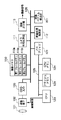
図2は、本発明の第1の実施形態における撮像装置として、デジタルビデオカメラ(以下、「カメラ」と呼ぶ。)の構成を表すブロック図である。カメラの起動時から、CPU120は、フラッシュメモリ123内のプログラムに従って動作することで、後述の各種動作の制御を行う。
FIG. 2 is a block diagram illustrating a configuration of a digital video camera (hereinafter referred to as “camera”) as the imaging apparatus according to the first embodiment of the present invention. The
被写体からの光は、レンズ群101を通して撮像素子102上に結像される。撮像素子102上に結像された被写体像は光電変換され、CDS・A/D回路103にて、サンプルホールドされた後にアナログ信号からデジタル信号へと変換される。ラインメモリ104では、CDS・A/D回路103から出力された1ライン分のデジタル信号を一旦蓄積し、蓄積したデジタル信号の内、後述する所定範囲のデジタル信号を画像バス126へ流す。なお、後述する画像メモリ110、カメラ信号処理回路111、画像処理回路112、映像出力回路113は、画像バス126に接続されており、画像バス126を介して画像データをやり取りする。
Light from the subject is imaged on the
画像メモリ110は、ラインメモリ104から出力された画像データを1フレーム分一時的に蓄積する。カメラ信号処理部111は、画像メモリ110に蓄積された画像データを標準的な画像データになるように処理する。画像処理部112は、画像の拡大や縮小、画像同士の加算やフレーム変換処理などを行う。また、映像出力部113は、デジタル画像データを一般的なNTSCやPALなどの標準TV信号に変換する。
The
一方、バスブリッジ121を介して、CPUバス125には、CPU120、フラッシュメモリ123、CPUメモリ124が接続されている。CPU120は全体の制御を行い、フラッシュメモリ123にはCPU120を動作させるためのプログラムや各種パラメータ値が格納されており、CPUメモリ124はCPUを動作させるためのワークメモリとして使用される。
On the other hand, a
また、角速度センサ105がCPU120に接続されており、角速度センサ105で検出した角速度はCPU120で処理することで、カメラの手ぶれ情報に変換され、撮像素子102やラインメモリ104を制御することで、手ぶれ補正動作を行う。この角速度センサ105はレンズ群101の光軸に対して垂直な2軸を検出することで、撮影に有害な手ぶれを検出する。
Also, an
図3は、本発明の第1の実施形態における手ぶれ補正動作を説明するための概念図である。CPU120は、角速度センサ105の出力から得られる垂直方向の手ぶれ情報に基づいて、撮像素子102の出力のうち、図3(a)に表すように、直前のフレームで切り出した画像における被写体の位置が、現フレームで切り出した画像においてほぼ同じ位置となるように、撮像素子102からの画像信号の読み出しを制御する。
FIG. 3 is a conceptual diagram for explaining a camera shake correction operation in the first embodiment of the present invention. Based on the camera shake information in the vertical direction obtained from the output of the
まず垂直方向について、図3(b)に表すように、垂直位置のV1からV2までの間の画像信号のみを、CDS・A/D103へ出力するように制御する。つまり、垂直方向の手ぶれが補正されるように、V1、V2の読み出し開始/終了位置を、撮像素子102から1枚の画像を読み出すタイミング毎に決定する。CDS・A/D103から出力された1ライン分のデジタル画像信号はラインメモリ104に一旦記憶する。
First, in the vertical direction, as shown in FIG. 3B, only the image signal between V1 and V2 at the vertical position is controlled to be output to the CDS / A /
次に、CPU120は、角速度センサ105の出力から得られる水平方向の手ぶれ情報に基づいて、図3(c)に表すように、ラインメモリ104に記憶された画像信号のうち、水平位置のH1からH2までの間の画像信号のみを、画像バス126へ出力するように制御する。つまり、水平方向の手ぶれが補正されるように、H1、H2の読み出し開始/終了位置を、撮像素子102から1枚の映像を画像を読み出すタイミング毎に決定する。
Next, based on the horizontal camera shake information obtained from the output of the
次に、外部検出センサである角速度センサ105を用いて手ぶれ検出を行い、プログレッシブ動画撮影を行う場合の動作における、図1で説明した通常撮影モード、撮像素子蓄積スローシャッターモード、及びメモリ蓄積スローシャッターモードのそれぞれの信号の流れやタイミングについて、図4を参照して説明する。
Next, the normal shooting mode, the image sensor accumulation slow shutter mode, and the memory accumulation slow shutter described with reference to FIG. 1 in the operation when the camera shake detection is performed using the
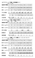
図4(a)は、通常撮影モードにおける画像信号の読み出し及び信号処理のタイミングを表した図、図4(b)は、撮像素子蓄積スローシャッターモードにおける画像信号の読み出し及び信号処理のタイミングを表した図、図4(c)は、メモリ蓄積スローシャッターモードにおける画像信号の読み出し及び信号処理のタイミングを表した図である。 4A shows the timing of image signal readout and signal processing in the normal shooting mode, and FIG. 4B shows the timing of image signal readout and signal processing in the image sensor accumulation slow shutter mode. FIG. 4C is a diagram showing the timing of image signal reading and signal processing in the memory accumulation slow shutter mode.
(1)通常撮影モード
最初に、図4(a)に示す通常撮影モードの動作について説明する。まず、撮像素子102は、蓄積時間T1の間、被写体からの光を光電変換して電荷を蓄積する。この蓄積時間T1の間に、CPU120は角速度センサ105の出力から手ぶれ情報を取得し、手ぶれ情報の平均値を算出する。この算出した値に基づいて、図3を参照して上述したようにして、CPU120は撮像素子102からの読み出しタイミング及びラインメモリ104からの読み出しタイミングを制御して、画像を切り出して読み出すことにより手ぶれ補正を行う。このようにして切り出した1フレーム分の画像信号を画像メモリ110に記憶する。
(1) Normal Shooting Mode First, the operation in the normal shooting mode shown in FIG. First, the
画像メモリ110に記憶された画像信号は、垂直同期のタイミングで後段のカメラ信号処理部111、画像処理部112、映像出力部113を介して標準的な映像信号に変換された後、不図示のディスプレイ等の画像出力装置に出力され、表示される。なお、このときの垂直同期の期間Tvは、撮像素子102の蓄積時間T1に等しい。上述した読み出しから表示出力までの処理を繰り返すことにより、動画の撮影が行われる。
The image signal stored in the
(2)撮像素子蓄積スローシャッターモード
次に、図4(b)に示す撮像素子蓄積スローシャッターモードの動作について説明する。撮像素子蓄積スローシャッターモードは、被写体が暗く、カメラの揺れが小さい場合に設定されるモードである。
(2) Image Sensor Accumulation Slow Shutter Mode Next, the operation of the image sensor accumulation slow shutter mode shown in FIG. 4B will be described. The image sensor accumulation slow shutter mode is a mode set when the subject is dark and the camera shake is small.
撮像素子蓄積スローシャッターモードでは、通常撮影モードの2倍の蓄積時間T2の間、撮像素子102を露光する。この蓄積時間T2の間に、CPU120は角速度センサ105の出力から手ぶれ情報を取得し、手ぶれ情報の平均値を算出する。この算出した値に基づいて、図3を参照して上述したようにして、CPU120は撮像素子102からの読み出しタイミング及びラインメモリ104からの読み出しタイミングを制御して、画像を切り出して読み出すことにより手ぶれ補正を行う。このようにして切り出した1フレーム分の画像信号を画像メモリ110に記憶する。
In the image sensor accumulation slow shutter mode, the
画像メモリ110に記憶された画像信号は、垂直同期のタイミングで後段のカメラ信号処理部111、画像処理部112、映像出力部113を介して標準的な映像信号に変換された後、不図示のディスプレイ等の画像出力装置に出力され、表示される。ただし、この場合、図4(b)から分かるように、撮像素子蓄積スローシャッターモードでは撮像素子102の蓄積時間が通常撮影モードの2倍であるために、蓄積時間T1に対応する時間おきに画像が画像メモリ110に記憶されることになる。また、垂直同期の期間Tvが蓄積時間T2の1/2なので、同じ画像を2回繰り返し出力することになり、画像の更新周期が垂直同期の期間Tvの2回に1度になる。さらに、手ぶれ補正の周期も周期Tvの2回に1度になるために、手ぶれ補正の特性が通常撮影モードに比べて劣るが、暗い被写体を撮影する場合に、蓄積時間を通常撮影モードの2倍とすることで撮像素子102に蓄積される電荷量をより多くできるので、ノイズの少ない、より明るい画像を取得することができる。
The image signal stored in the
(3)メモリ蓄積スローシャッターモード
最後に、図4(c)に示すメモリ蓄積スローシャッターモードの動作について説明する。メモリ蓄積スローシャッターモードは、被写体が暗く、撮像装置の揺れが大きい場合に設定されるモードである。
(3) Memory Accumulation Slow Shutter Mode Finally, the operation of the memory accumulation slow shutter mode shown in FIG. 4C will be described. The memory accumulation slow shutter mode is a mode set when the subject is dark and the shaking of the imaging apparatus is large.
メモリ蓄積スローシャッターモードでは、通常撮影モードと同じ蓄積時間T1の間、撮像素子102を露光する。この蓄積時間T1の間に、CPU120は角速度センサ105の出力から手ぶれ情報を取得し、手ぶれ情報の平均値を算出する。この算出した値に基づいて、図3を参照して上述したようにして、CPU120は撮像素子102からの読み出しタイミング及びラインメモリ104からの読み出しタイミングを制御して、画像を切り出して読み出すことにより手ぶれ補正を行う。このようにして切り出した1フレーム分の画像信号を画像メモリ110に記憶する。
In the memory accumulation slow shutter mode, the
その後、同様にして蓄積時間T1の間、撮像素子102を露光して手ぶれ補正した1フレーム分の画像信号を取得し、画像処理部112において画像メモリ110に記憶されている画像信号に加算する。加算した画像信号は、再び画像メモリ110に記憶される。
Thereafter, in the same manner, during the accumulation time T1, the
画像メモリ110に記憶された画像信号は、垂直同期のタイミングで後段のカメラ信号処理部111、画像処理部112、映像出力部113を介して標準的な映像信号に変換された後、不図示のディスプレイ等の画像出力装置に出力され、表示される。この場合、垂直同期の期間Tvは、各フレームの蓄積時間T1と同じである。しかしながら、画像メモリ110に加算画像信号が蓄積されるのは蓄積時間T1の2回に1回なので、同じ画像を2回繰り返し出力することになり、画像の更新周期が垂直同期の期間Tvの2回に1度になるが、暗い被写体を撮影する場合に、より明るい画像を取得することができる。
The image signal stored in the
このように、メモリ蓄積スローシャッターモードでは、撮像素子蓄積スローシャッターモードのように撮像素子102に1度に長時間蓄積するのではなく、蓄積時間T1で読み出した画像信号を2フレーム分加算して撮像信号を生成するので、ノイズ量が撮像素子蓄積スローシャッターモードに比べて多くなるが、手ぶれ補正を各フレーム毎に行うために、その特性は通常撮影モードと同等になり、カメラの揺れが大きい場合であっても手ぶれ補正の効果の高い画像を取得することができる。
As described above, in the memory accumulation slow shutter mode, instead of accumulating in the
このように、本第1の実施形態によれば、被写体の明るさ及び撮像装置の揺れの度合いに応じて画像読み出し及び手ぶれ補正の仕方を変えることにより、より高画質な画像を取得することができる。 As described above, according to the first embodiment, it is possible to acquire a higher quality image by changing the method of image readout and camera shake correction according to the brightness of the subject and the degree of shaking of the imaging device. it can.
<第2の実施形態>
次に、本発明の第2の実施形態について説明する。
<Second Embodiment>
Next, a second embodiment of the present invention will be described.
第2の実施形態では、外部検出センサである角速度センサ105を用いて手ぶれ検出を行い、インターレース動画撮影を行う場合の動作における、図1で説明した通常撮影モード、撮像素子蓄積スローシャッターモード、及びメモリ蓄積スローシャッターモードのそれぞれの信号の流れやタイミングについて、図5を参照して説明する。なお、本第2の実施形態では、第1の実施形態において説明した図2に示すデジタルビデオカメラを使用し、図3を参照して説明した手ぶれ補正動作を行うものとし、それらの説明は省略する。
In the second embodiment, camera shake detection is performed using the
(1)通常撮影モード
最初に、図5(a)に示す通常撮影モードの動作について説明する。まず、撮像素子102は、蓄積時間T1の間、被写体からの光を光電変換して電荷を蓄積する。この蓄積時間T1の間に、CPU120は角速度センサ105の出力から手ぶれ情報を取得し、手ぶれ情報の平均値を算出する。この算出した値に基づいて、図3を参照して上述したようにして、CPU120は撮像素子102からの読み出しタイミング及びラインメモリ104からの読み出しタイミングを制御して、画像を切り出して1ラインおきに読み出すことにより各フィールド画像の手ぶれ補正を行う。このようにして切り出した1フィールド分の画像信号(例えば、図5(a)の「1奇」)を画像メモリ110に記憶する。以降、直前の蓄積時間T1で蓄積した画像信号を読み出したラインと異なるラインの信号を読み出すことで、1フィールド分の画像信号(例えば、図5(a)の「2偶」、「3奇」、「4偶」等)を画像メモリ110に記憶する。ここで、「奇」は奇数フィールドを、「偶」は偶数フィールドを示している。
(1) Normal Shooting Mode First, the operation in the normal shooting mode shown in FIG. First, the
画像メモリ110に記憶された1フィールド分の画像信号は、後段のカメラ信号処理部111、画像処理部112、映像出力部113を介して標準的な映像信号に変換された後、垂直同期のタイミングで奇数フィールドと偶数フィールドの画像信号が交互に不図示のディスプレイ等の画像出力装置に出力され、表示される。なお、このときの垂直同期の期間Tvは、撮像素子102の蓄積時間T1に等しい。
The image signal for one field stored in the
(2)撮像素子蓄積スローシャッターモード
次に、図5(b)に示す撮像素子蓄積スローシャッターモードの動作について説明する。
(2) Image Sensor Accumulation Slow Shutter Mode Next, the operation of the image sensor accumulation slow shutter mode shown in FIG. 5B will be described.
撮像素子蓄積スローシャッターモードでは、通常撮影モードの2倍の蓄積時間T2の間、撮像素子102を露光する。この蓄積時間T2の間に、CPU120は角速度センサ105の出力から手ぶれ情報を取得し、手ぶれ情報の平均値を算出する。この算出した値に基づいて、図3を参照して上述したようにして、CPU120は撮像素子102からの読み出しタイミング及びラインメモリ104からの読み出しタイミングを制御して、画像を切り出して1ラインおきに読み出すことにより各フィールド画像の手ぶれ補正を行う。このようにして切り出した1フィールド分の画像信号(例えば、図5(b)の「1奇」)を画像メモリ110に記憶する。以降、同様にして蓄積時間T2毎に画像を切り出し、1フィールド分の画像信号を画像メモリ110に記憶する。なお、図5(b)の例では奇数フィールドのみを読み出す場合を示しているが、偶数フィールドのみを読み出すようにしても構わない。
In the image sensor accumulation slow shutter mode, the
画像メモリ110に記憶された1フィールド分の画像信号は、後段のカメラ信号処理部111、画像処理部112、映像出力部113を介して標準的な片フィールドの映像信号に変換されるとともに、この片フィールド(図5(b)の例では奇数フィールド)からもう一つのフィールド(図5(b)の例では偶数フィールド)の画像信号を生成され、垂直同期のタイミングで奇数フィールドと偶数フィールドの画像信号が交互に不図示のディスプレイ等の画像出力装置に出力され、表示される。なお、この時の垂直同期の期間Tvは、蓄積時間T2の1/2であるが、片フィールド(図5(b)の例では奇数フィールド)からもう一つのフィールド(図5(b)の例では偶数フィールド)を生成するため、画像の更新周期は垂直同期の期間Tvと等しくなる。
The image signal for one field stored in the
手ぶれ補正の周期は垂直同期の期間Tvの2回に1度になるため、手ぶれ補正の特性が通常撮影モードに比べて劣るが、暗い被写体を撮影する場合に、蓄積時間を通常撮影モードの2倍とすることで撮像素子102に蓄積される電荷量をより多くしたので、ノイズの少ない、より明るい画像を取得することができる。
Since the camera shake correction cycle is once every two vertical synchronization periods Tv, the camera shake correction characteristics are inferior to those in the normal shooting mode. However, when shooting a dark subject, the accumulation time is set to 2 in the normal shooting mode. Since the amount of charge accumulated in the
(3)メモリ蓄積スローシャッターモード
最後に、図5(c)に示すメモリ蓄積スローシャッターモードの動作について説明する。
(3) Memory Accumulation Slow Shutter Mode Finally, the operation of the memory accumulation slow shutter mode shown in FIG.
メモリ蓄積スローシャッターモードでは、通常撮影モードと同じ蓄積時間T1の間、撮像素子102を露光する。この蓄積時間T1の間に、CPU120は角速度センサ105の出力から手ぶれ情報を取得し、手ぶれ情報の平均値を算出する。この算出した値に基づいて、図3を参照して上述したようにして、CPU120は撮像素子102からの読み出しタイミング及びラインメモリ104からの読み出しタイミングを制御して、画像を切り出して1ラインおきに読み出すことにより各フィールド画像の手ぶれ補正を行う。このようにして切り出した1フィールド分の画像信号(例えば、図5(c)の「1奇」)を画像メモリ110に記憶する。なお、図5(c)の例では奇数フィールドのみを読み出す場合を示しているが、偶数フィールドのみを読み出すようにしても構わない。
In the memory accumulation slow shutter mode, the
その後、同様にして蓄積時間T1の間、撮像素子102を露光して手ぶれ補正した1フィールド分の画像信号(例えば、図5(c)の「1奇」)を取得し、画像処理部112において画像メモリ110に記憶されている画像信号に加算する。加算した画像信号(例えば、図5(c)の「1奇+2奇」)は、再び画像メモリ110に記憶される。
Thereafter, in the same way, during the accumulation time T1, an image signal for one field (for example, “1 odd” in FIG. 5C) obtained by exposing the
以降、同様にして、蓄積時間T1毎に画像を切り出し、1フィールド分の画像信号を画像メモリ110に記憶する動作と、読み出した画像信号を画像メモリ110にすでに記憶してある画像信号に加算してから再び画像メモリ110に記憶する動作とを交互に繰り返す。
Thereafter, in the same manner, an image is cut out at every accumulation time T1, and an operation for storing the image signal for one field in the
なお、図5(c)の例では奇数フィールドのみを読み出す場合を示しているが、偶数フィールドのみを読み出すようにしても構わない。 In the example shown in FIG. 5C, only the odd field is read, but only the even field may be read.
このようにして、画像メモリ110に記憶された1フィールド分の画像信号は、後段のカメラ信号処理部111、画像処理部112、映像出力部113を介して標準的な片フィールドの映像信号に変換されるとともに、この片フィールド(図5(c)の例では奇数フィールド)の画像信号(例えば、「1奇+2奇、奇」)からもう一つのフィールド(図5(c)の例では偶数フィールド)の画像信号(例えば、「1奇+2奇、偶」)が生成され、垂直同期のタイミングで不図示のディスプレイ等の画像出力装置に出力され、表示される。この場合、垂直同期の期間Tvは、蓄積時間T1と同じであるが、画像メモリ110に加算画像信号が蓄積されるのは垂直同期の期間Tvの2回に1回である。しかし、片フィールド(例えば、奇数フィールド)からもう一つのフィールド(例えば、偶数フィールド)を生成するため、画像の更新周期は垂直同期の期間Tvと等しくなる。
In this way, the image signal for one field stored in the
このように、メモリ蓄積スローシャッターモードでは、撮像素子蓄積スローシャッターモードのように撮像素子102で1度に長時間電荷を蓄積するのではなく、蓄積時間T1で読み出した画像信号を2フィールド分加算して撮像信号を生成するので、暗い被写体を撮影する場合に、より明るい画像を取得することができる。この場合、ノイズ量が撮像素子蓄積スローシャッターモードに比べて多くなるが、手ぶれ補正を各フィールド毎に行うため、その特性は通常撮影モードと同等になり、撮像装置の揺れが大きい場合であっても手ぶれ補正の効果の高い画像を取得することができる。
As described above, in the memory accumulation slow shutter mode, the
<第3の実施形態>
次に、本発明の第3の実施形態について説明する。
<Third Embodiment>
Next, a third embodiment of the present invention will be described.
本第3の実施形態では、外部検出センサである角速度センサ105を用いて手ぶれ検出を行い、プログレッシブ動画撮影を行う場合の動作における、図1で説明したメモリ蓄積スローシャッターモードの別の動作について、図6を参照して説明する。なお、本第3の実施形態では、第1の実施形態において説明した図2に示すデジタルビデオカメラを使用し、図3を参照して説明した手ぶれ補正動作を行うものとし、それらの説明は省略する。ただし、画像メモリ110は少なくとも2枚のフレーム画像の画像信号を格納するために十分な容量を備えているものとし、ここでは便宜上、第1フレームメモリ110a及び第2フレームメモリ110bと呼ぶ。
In the third embodiment, another operation of the memory accumulation slow shutter mode described with reference to FIG. 1 in the operation when the camera shake detection is performed using the
(3)メモリ蓄積スローシャッターモード
図6に示すメモリ蓄積スローシャッターモードでは、通常撮影モードと同じ蓄積時間T1の間、撮像素子102を露光する。この蓄積時間T1の間に、CPU120は角速度センサ105の出力から手ぶれ情報を取得し、手ぶれ情報の平均値を算出する。この算出した値に基づいて、図3を参照して上述したようにして、CPU120は撮像素子102からの読み出しタイミング及びラインメモリ104からの読み出しタイミングを制御して、画像を切り出して読み出すことにより手ぶれ補正を行う。このようにして切り出した1フレーム分の画像信号(例えば、図6の「1」)を、第1フレームメモリ110aに記憶する。
(3) Memory Accumulation Slow Shutter Mode In the memory accumulation slow shutter mode shown in FIG. 6, the
次に、同様にして蓄積時間T1の間、撮像素子102を露光して手ぶれ補正した1フレーム分の画像信号(例えば、図6の「2」)を取得し、画像処理部112において第1フレームメモリ110aに記憶されている画像信号(例えば、図6の「1」)を読み出して加算し、加算した画像信号(例えば、図6の「1+2」)を第2フレームメモリ110bに記憶する。この加算処理と並行して、新たに取得した画像信号(例えば、図6の「2」)を第1フレームメモリ110aに記憶する。
Next, in the same manner, during the accumulation time T1, an image signal (for example, “2” in FIG. 6) obtained by exposing the
このように、第1フレームメモリ110aに記憶された1フレーム前の画像信号に、新たに取得した画像信号を加算して第2フレームメモリ110bに記憶するとともに、新たに取得した画像信号を第1フレームメモリ110aに記憶することにより、第2フレームメモリ110bには、新たに取得した画像信号と、その1フレーム前に取得した画像信号とを加算した画像信号が記憶されることになる。
In this manner, the newly acquired image signal is added to the image signal of the previous frame stored in the
次に、垂直同期のタイミングで、第2フレームメモリ110bに記憶された画像信号を読み出してカメラ信号処理部111、画像処理部112、映像出力部113を介して標準的な映像信号に変換した後、不図示のディスプレイ等の画像出力装置に出力され、表示される。
Next, after the image signal stored in the
本第3の実施形態では、蓄積時間T1毎に第2フレームメモリ110bに新しい加算画像信号が記憶されるため、各垂直同期の期間Tv毎に画像が更新される。なお、蓄積時間T1で読み出した画像信号を2フレーム分加算して撮像信号を生成するので、暗い被写体を撮影する場合に、より明るい画像を取得することができるが、ノイズ量が撮像素子蓄積スローシャッターモードに比べて多くなる。しかしながら、手ぶれ補正を各フレーム毎に行うために、その特性は通常撮影モードと同等になり、撮像装置の揺れが大きい場合であっても手ぶれ補正の効果の高い画像を取得することができる。
In the third embodiment, since a new added image signal is stored in the
<第3の実施形態の変形例>
上記第3の実施形態では、画像メモリ110に2枚のフレーム画像を記憶する場合について説明したが、3枚以上のフレーム画像を記憶可能な容量を有する画像メモリ110を用いることにより、3枚以上のフレーム画像を加算することが可能になり、より暗い被写体を撮影する場合にも、通常撮影モードと同等の手ぶれ補正特性を保ったまま、より明るい画像を取得することができる。
<Modification of Third Embodiment>
In the third embodiment, the case where two frame images are stored in the
(3)メモリ蓄積スローシャッターモード
図7は、プログレッシブ動画撮影を行った際のメモリ蓄積スローシャッターモードの別の動作を示す図で、通常撮影モードの4倍の露光時間分の画像信号を加算する場合の信号の流れ及びタイミングを表した図である。この場合、画像メモリ110は少なくとも4枚のフレーム画像の画像信号を格納するために十分な容量を備えているものとし、ここでは便宜上、第1フレームメモリ110a、第2フレームメモリ110b、第3フレームメモリ110c、第4フレームメモリ110dと呼ぶ。
(3) Memory Accumulation Slow Shutter Mode FIG. 7 is a diagram showing another operation of the memory accumulation slow shutter mode at the time of performing progressive video shooting, and adds image signals for an exposure time four times that of the normal shooting mode. It is a figure showing the flow and timing of a signal in the case. In this case, it is assumed that the
図7に示すメモリ蓄積スローシャッターモードでは、通常撮影モードと同じ蓄積時間T1の間、撮像素子102を露光する。この蓄積時間T1の間に、CPU120は角速度センサ105の出力から手ぶれ情報を取得し、手ぶれ情報の平均値を算出する。この算出した値に基づいて、図3を参照して上述したようにして、CPU120は撮像素子102からの読み出しタイミング及びラインメモリ104からの読み出しタイミングを制御して、画像を切り出して読み出すことにより手ぶれ補正を行う。このようにして切り出した1フレーム分の画像信号(例えば、図7の「1」)を第1フレームメモリ110aに記憶する。
In the memory accumulation slow shutter mode shown in FIG. 7, the
次に、同様にして蓄積時間T1の間、撮像素子102を露光して手ぶれ補正した1フレーム分の画像信号(例えば、図7の「2」)を取得し、画像処理部112において第1フレームメモリ110aに記憶されている画像信号(例えば、図7の「1」)を読み出して加算し、加算した画像信号(例えば、図7の「1+2」)を第2フレームメモリ110bに記憶する。この加算処理と並行して、新たに取得した画像信号(例えば、図7の「2」)を第1フレームメモリ110aに記憶する。
Next, in the same way, during the accumulation time T1, an image signal (for example, “2” in FIG. 7) of one frame obtained by exposing the
更に、同様にして蓄積時間T1の間、撮像素子102を露光して手ぶれ補正した1フレーム分の画像信号(例えば、図7の「3」)を取得し、画像処理部112において第1フレームメモリ110aに記憶されている画像信号(例えば、図7の「2」)を読み出して加算し、加算した画像信号(例えば、図7の「2+3」)を第2フレームメモリ110bに記憶する。また、画像処理部112において第2フレームメモリ110bに記憶されている画像信号(例えば、図7の「1+2」)を読み出して新たに取得した画像信号(例えば、図7の「3」)を加算し、加算した画像信号(例えば、図7の「1+2+3」)を第3フレームメモリ110dに記憶する。これらの加算処理と並行して、新たに取得した画像信号(例えば、図7の「3」)を第1フレームメモリ110aに記憶する。
Further, similarly, during the accumulation time T1, an image signal (for example, “3” in FIG. 7) obtained by exposing the
更に、蓄積時間T1の間、撮像素子102を露光して手ぶれ補正した1フレーム分の画像信号(例えば、図7の「4」)を取得し、同様にして第1〜第3フレームメモリ110a〜110cに記憶された画像信号に加算し、加算した画像信号(例えば、図7の例では「3+4」、「2+3+4」、「1+2+3+4」)を第2〜第4フレームメモリ110b〜110dに記憶するとともに、新たに取得した画像信号(例えば、図7の「4」)を第1フレームメモリ110aに記憶する。
Further, during the accumulation time T1, an image signal (for example, “4” in FIG. 7) obtained by correcting the camera shake by exposing the
上記制御により、第4フレームメモリ110dには、新たに取得した画像信号と、その3フレーム前までに取得した画像信号すべてを加算した画像信号が記憶されることになる。なお、第4フレームメモリ110dからの画像信号の読み出しから表示までの処理は第3の実施形態と同様であるので、ここでは説明を省略する。 With the above control, the image signal obtained by adding the newly acquired image signal and all the image signals acquired up to three frames before is stored in the fourth frame memory 110d. Note that the processing from the reading of the image signal from the fourth frame memory 110d to the display is the same as that in the third embodiment, and thus the description thereof is omitted here.
このように、本変形例におけるメモリ蓄積スローシャッターモードでは、蓄積時間T1で読み出した画像信号を4フレーム分加算して撮像信号を生成するので、より暗い被写体を撮影する場合に、明るい画像を取得することができるが、ノイズ量が撮像素子蓄積スローシャッターモードに比べて多くなる。しかしながら、手ぶれ補正を各フレーム毎に行うために、その特性は通常撮影モードと同等になり、撮像装置の揺れが大きい場合であっても手ぶれ補正の効果の高い画像を取得することができる。 As described above, in the memory accumulation slow shutter mode in the present modification, the image signal read at the accumulation time T1 is added for four frames to generate the imaging signal, so that a bright image is obtained when shooting a darker subject. However, the amount of noise is larger than that in the image sensor accumulation slow shutter mode. However, since camera shake correction is performed for each frame, the characteristics thereof are the same as those in the normal shooting mode, and an image with a high effect of camera shake correction can be obtained even when the image pickup apparatus shakes greatly.
なお、4フレームに限るものではなく、画像メモリ110の容量に応じて、任意のフレーム数の画像信号を加算可能に制御できることは言うまでも無い。
Needless to say, the number of image signals is not limited to four frames, and an arbitrary number of image signals can be added according to the capacity of the
また、第3の実施形態及びその変形例では、プログレッシブ動画撮影の場合について説明したが、第2の実施形態で説明したインターレース動画撮影にも適用可能であることは言うまでもない。 In the third embodiment and its modifications, the case of progressive moving image shooting has been described, but it goes without saying that it can also be applied to the interlaced moving image shooting described in the second embodiment.
その場合、蓄積時間T1毎に偶数または奇数フィールドのいずれか一方から信号を読み出すように制御し、画像処理部112において加算した信号に基づいて、1フィールド期間おきにもう一方のフィールドの信号を生成し、この生成した1フィールド分の信号と、画像処理部112から出力された加算信号とを交互に出力するようにする。例えば、図7に示す例では、生成した信号を「’」で表すとすると、「1+2+3+4」、「(2+3+4+5)’」、「3+4+5+6」、「(4+5+6+7)’」といったように出力する。
In that case, control is performed so that the signal is read from either the even field or the odd field every accumulation time T1, and the signal of the other field is generated every other field period based on the signal added in the
なお、被写体が暗く、撮像装置の揺れが大きい場合に、メモリ蓄積スローシャッターモードに移行し、上述した第3の実施形態及びその変形例に示す制御を行う場合について説明したが、ユーザーが手動で上述した制御を行うように切り替えるように構成しても良い。 Although the case where the subject is dark and the image pickup apparatus shakes greatly is described in the case of shifting to the memory accumulation slow shutter mode and performing the control described in the third embodiment and the modification thereof, the user manually You may comprise so that it may switch so that the control mentioned above may be performed.
<第4の実施形態>
次に、本発明の第4の実施形態について説明する。
<Fourth Embodiment>
Next, a fourth embodiment of the present invention will be described.
図8は、本発明の第4の実施形態における撮像装置として、デジタルビデオカメラ(以下、「カメラ」と呼ぶ。)の構成を表すブロック図である。なお、第1の実施形態で説明した図2の構成と同様の構成には同じ符号を付し、説明を省略する。図8に示すカメラの構成では、角速度センサ105及びラインメモリ104が無く、画像ベクトル検出部801が加えられ、画像バス126に接続されているところが図2に示す構成と異なる。また、本第4の実施形態では、画像メモリ110は少なくとも3枚のフレーム画像分の画像信号を蓄積可能な容量を有し、ここでは便宜上、第1フレームメモリ110a、第2フレームメモリ110b、及び第3フレームメモリ110cと呼ぶ。なお、第1及び第2のフレームメモリ110a、110bは、それぞれ撮像素子102から読み出した信号を全て記憶可能な容量が必要であるが、第3フレームメモリ110cは、撮像素子102から読み出した信号の内、手ぶれ補正のために切り出して読み出した分の画像信号を記憶可能な容量であればよい。
FIG. 8 is a block diagram showing a configuration of a digital video camera (hereinafter referred to as “camera”) as an imaging apparatus according to the fourth embodiment of the present invention. In addition, the same code | symbol is attached | subjected to the structure similar to the structure of FIG. 2 demonstrated in 1st Embodiment, and description is abbreviate | omitted. The camera configuration shown in FIG. 8 is different from the configuration shown in FIG. 2 in that the
まず、被写体からの光は、レンズ群101を通して撮像素子102上に結像される。撮像素子102上に結像された被写体像は光電変換され、CDS・A/D回路103にて、サンプルホールドされた後にアナログ信号からデジタル信号へと変換される。こうして得られたデジタル画像信号は、画像バス126へ流され、各フレーム画像の読み出し毎に第1フレームメモリ110a及び第2フレームメモリ110bのいずれかに交互に一時的に蓄積される。
First, light from the subject is imaged on the
画像ベクトル検出部801は、第1フレームメモリ110a及び第2フレームメモリ110bに一時的に蓄積された、連続的に得られた2つの画像を比較することで画像の動きベクトルを検出し、検出した動きベクトルから撮影に有害な画像の手ぶれ情報を検出する。
The image
本第4の実施形態においても、図3(a)を参照して説明した画像切り出し方法と同様の概念による方法により手ぶれ補正を行うが、角速度センサ105の出力からの手ぶれ情報の代わりに、画像ベクトル検出回路801の出力から得られる水平方向と垂直方向の手ぶれ情報に基づいて手ぶれ補正を行うと共に、画像メモリ110に蓄積された撮像素子102のすべての画素の画像信号の内、V1からV2までの垂直位置及びH1からH2までの水平位置の画像信号のみを読み出すことで、手ぶれを補正する。
Also in the fourth embodiment, camera shake correction is performed by a method based on the same concept as the image clipping method described with reference to FIG. 3A, but instead of image stabilization information from the output of the
次に、画像ベクトル検出部801を用いて手ぶれ検出を行い、プログレッシブ動画撮影を行う場合の動作における、図1で説明した通常撮影モード、撮像素子蓄積スローシャッターモード、及びメモリ蓄積スローシャッターモードのそれぞれの信号の流れやタイミングについて、図9を参照して説明する。
Next, each of the normal shooting mode, the image sensor accumulation slow shutter mode, and the memory accumulation slow shutter mode described with reference to FIG. 1 in the operation in the case of performing camera shake detection using the image
(1)通常撮影モード
最初に、図9(a)に示す通常撮影モードの動作について説明する。まず、撮像素子102は、蓄積時間T1の間、被写体からの光を光電変換して電荷を蓄積し、蓄積時間T1終了後、電荷信号を撮像素子102からCDS・A/D103を介して第1フレームメモリ110a及び第2フレームメモリ110bに交互に読み出す動作を繰り返し行う。画像ベクトル検出回路801は、新たに読み出した画像(例えば、第2フレームメモリ110bに記憶された「2」)と、1フレーム前に読み出した画像(例えば、第1フレームメモリ110aに記憶された「1」)とを比較して動きベクトルを検出し、検出した動きベクトルに基づいて、新たに読み出した画像(上述の例の場合、「2」)の手ぶれ情報を検出する。なお、図9の手ぶれ検出の各パルス横の( )の数字は、手ぶれ情報を検出する画像を示している。
(1) Normal Shooting Mode First, the operation in the normal shooting mode shown in FIG. 9A will be described. First, the
次に、垂直同期のタイミングで、検出した手ぶれ情報に基づいて、第1フレームメモリ110aまたは第2フレームメモリ110bの水平及び垂直方向の読み出し位置を制御して、新たに読み出した画像(例えば、フレームメモリ110bに記憶された「2」)を切り出して読み出すことにより手ぶれ補正を行い、カメラ信号処理部111へと画像信号を送る。
Next, at the timing of vertical synchronization, based on the detected camera shake information, the horizontal and vertical readout positions of the
画像信号は、カメラ信号処理部111、画像処理部112、映像出力部113を介して標準的な映像信号に変換された後、不図示のディスプレイ等の画像出力装置に出力され、表示される。なお、このときの垂直同期の期間Tvは、撮像素子102の蓄積時間T1に等しい。上述した読み出しから表示出力までの処理を繰り返すことにより、動画の撮影が行われる。
The image signal is converted into a standard video signal via the camera
(2)撮像素子蓄積スローシャッターモード
次に、図9(b)に示す撮像素子蓄積スローシャッターモードの動作について説明する。
(2) Image Sensor Accumulation Slow Shutter Mode Next, the operation of the image sensor accumulation slow shutter mode shown in FIG. 9B will be described.
撮像素子蓄積スローシャッターモードでは、通常撮影モードの2倍の蓄積時間T2の間、撮像素子102を露光して電荷を蓄積し、蓄積時間T2終了後、電荷信号を撮像素子102からCDS・A/D103を介してフレームメモリ110a及びフレームメモリ110bに交互に読み出す動作を繰り返し行う。画像ベクトル検出回路801は、新たに読み出した画像(例えば、第2フレームメモリ110bに記憶された「2」)と、1フレーム前に読み出した画像(例えば、第1フレームメモリ110aに記憶された「1」)とを比較して動きベクトルを検出し、検出した動きベクトルに基づいて、新たに読み出した画像(上述の例の場合、画像「2」)の手ぶれ情報を検出する。
In the image pickup device accumulation slow shutter mode, the
次に、垂直同期のタイミングで、検出した手ぶれ情報に基づいて、第1フレームメモリ110aまたは第2フレームメモリ110bの水平及び垂直方向の読み出し位置を制御して、新たに読み出した画像(例えば、フレームメモリ110bに記憶された「2」)を切り出して読み出すことにより手ぶれ補正を行い、カメラ信号処理部111へと画像信号を送る。
Next, at the timing of vertical synchronization, based on the detected camera shake information, the horizontal and vertical readout positions of the
画像信号は、カメラ信号処理部111、画像処理部112、映像出力部113を介して標準的な映像信号に変換された後、不図示のディスプレイ等の画像出力装置に出力され、表示される。ただし、この場合、図9(b)から分かるように、撮像素子蓄積スローシャッターモードでは撮像素子102の蓄積時間が通常撮影モードの2倍であるために、蓄積時間T1に対応する時間おきに画像がフレームメモリ110aまたはフレームメモリ110bに記憶されることになる。また、垂直同期の期間Tvが蓄積時間T2の1/2なので、同じ画像を2回繰り返し出力することになり、画像の更新周期が垂直同期の期間Tvの2回に1度になる。さらに、手ぶれ補正の周期も2V周期に一回になるために、手ぶれ補正の特性が通常撮影モードに比べて劣るが、暗い被写体を撮影する場合に、蓄積時間を通常撮影モードの2倍とすることで撮像素子102に蓄積される電荷量をより多くできるので、ノイズの少ない、より明るい画像を取得することができる。
The image signal is converted into a standard video signal via the camera
(3)メモリ蓄積スローシャッターモード
最後に、図9(c)に示すメモリ蓄積スローシャッターモードの動作について説明する。
(3) Memory Accumulation Slow Shutter Mode Finally, the operation of the memory accumulation slow shutter mode shown in FIG. 9C will be described.
メモリ蓄積スローシャッターモードでは、通常撮影モードと同じ蓄積時間T1の間、撮像素子102を露光して電荷を蓄積し、蓄積時間T1終了後、電荷信号を撮像素子102からCDS・A/D103を介して第1フレームメモリ110a及び第2フレームメモリ110bに交互に読み出す動作を繰り返し行う。画像ベクトル検出回路801は、新たに読み出し画像(例えば、第2フレームメモリ110bに記憶された「2」)と、1フレーム前に読み出した画像(例えば、第1フレームメモリ110aに記憶された「1」)とを比較して動きベクトルを検出し、動きベクトルに基づいて、新たに読み出した画像(上述の例の場合、「2」)の手ぶれ情報を検出する。
In the memory accumulation slow shutter mode, the
次に、垂直同期のタイミングで、検出した手ぶれ情報に基づいて、第1フレームメモリ110aまたは第2フレームメモリ110bの水平及び垂直方向の読み出し位置を制御して、新たに読み出した画像(例えば、第2フレームメモリ110bに記憶された「2」)を切り出して読み出すことにより手ぶれ補正を行う。
Next, at the timing of vertical synchronization, based on the detected camera shake information, the horizontal and vertical readout positions of the
切り出した画像(例えば、第1フレームメモリ110aに記憶された「1’」)は、第3フレームメモリ110cに記憶し、今回切り出した画像信号(例えば、「2’」)と、1フレーム前に切り出した画像信号(例えば、「1’」)とを画像処理部112により加算し、加算した画像信号(例えば、「1’+2’」)を第3フレームメモリ110cに再び記憶する。
The clipped image (for example, “1 ′” stored in the
第3フレームメモリ110cに記憶された画像信号は、垂直同期のタイミングで後段のカメラ信号処理部111、画像処理部112、映像出力部113を介して標準的な映像信号に変換された後、不図示のディスプレイ等の画像出力装置に出力され、表示される。この場合、垂直同期の期間Tvは、各フレームの蓄積時間T1と同じである。しかしながら、第3フレームメモリ110cに加算画像信号が蓄積されるのは蓄積時間T1の2回に1回なので、同じ画像を2回繰り返し出力することになり、画像の更新周期が垂直同期の期間の2回に1度になるが、暗い被写体を撮影する場合に、より明るい画像を取得することができる。
The image signal stored in the
このように、メモリ蓄積スローシャッターモードでは、撮像素子蓄積スローシャッターモードのように撮像素子102に1度に長時間蓄積するのではなく、蓄積時間T1で読み出した画像信号を2フレーム分加算して撮像信号を生成するので、ノイズ量が撮像素子蓄積スローシャッターモードに比べて多くなるが、手ぶれ補正を各フレーム毎に行うために、その特性は通常撮影モードと同等になり、カメラの揺れが大きい場合であっても手ぶれ補正の効果の高い画像を取得することができる。
As described above, in the memory accumulation slow shutter mode, instead of accumulating in the
<第5の実施形態>
次に、本発明の第5の実施形態について説明する。
<Fifth Embodiment>
Next, a fifth embodiment of the present invention will be described.
本第5の実施形態では、画像ベクトル検出部801を用いて手ぶれ検出を行い、インターレース動画撮影を行う場合の動作における、図1で説明した通常撮影モード、撮像素子蓄積スローシャッターモード、及びメモリ蓄積スローシャッターモードのそれぞれの信号の流れやタイミングについて、図10を参照して説明する。なお、本第5の実施形態では、第4の実施形態において説明した図8に示すデジタルビデオカメラを使用し、図3(a)を参照して説明した手ぶれ補正動作を行うものとし、説明を省略する。ただし、本第5の実施形態では、インターレース読み出しのため、画像メモリ110は少なくとも3枚のフィールド画像分の画像信号を蓄積できれば良く、ここでは便宜上、第1〜第3フィールドメモリ210a〜210c(不図示)と呼び、第1〜第3フレームメモリ110a〜110cの代わりに用いるものとする。
In the fifth embodiment, camera shake detection is performed using the image
(1)通常撮影モード
最初に、図10(a)に示す通常撮影モードの動作について説明する。まず、撮像素子102は、蓄積時間T1の間、被写体からの光を光電変換して電荷を蓄積し、蓄積時間T1終了後、1ラインおきに蓄積した電荷信号を読み出すことにより1フィールド分の電荷信号を撮像素子102からCDS・A/D103を介して第1フィールドメモリ210a及び第2フィールドメモリ210bに交互に読み出す動作を繰り返し行う。以降、直前の蓄積時間T1で蓄積した画像信号を読み出したラインと異なるラインの信号を読み出すことで、1フィールド分の画像信号(例えば、図10(a)の「1奇」、「2偶」、「3奇」、「4偶」等)を第1フィールドメモリ210a及び第2フィールドメモリ210bに交互に記憶する。ここで、「奇」は奇数フィールドを、「偶」は偶数フィールドを示している。
(1) Normal Shooting Mode First, the operation in the normal shooting mode shown in FIG. First, during the accumulation time T1, the
画像ベクトル検出回路801は、新たに読み出したフィールド画像(例えば、第2フィールドメモリ210bに記憶された「2偶」)と、1フィールド前に読み出したフィールド画像(例えば、第1フィールドメモリ210aに記憶された「1奇」)とを比較して動きベクトルを検出し、検出した動きベクトルに基づいて、新たに読み出したフィールド画像(例えば、第2フィールドメモリ210bに記憶された「2偶」)の手ぶれ情報を検出する。次に、垂直同期のタイミングでこの手ぶれ情報に基づいて、フィールドメモリ210aまたはフィールドメモリ210bの水平及び垂直方向の読み出し位置を制御して、新たに読み出した画像(例えば、第2フィールドメモリ210bに記憶された「2偶」)を切り出して読み出すことにより手ぶれ補正を行い、カメラ信号処理部111へと画像信号を送る。
The image
画像信号は、カメラ信号処理部111、画像処理部112、映像出力部113を介して標準的な映像信号に変換された後、奇数フィールドと偶数フィールドの画像信号が交互に不図示のディスプレイ等の画像出力装置に出力され、表示される。なお、このときの垂直同期の期間Tvは、撮像素子102の蓄積時間T1に等しい。
The image signal is converted into a standard video signal via the camera
(2)撮像素子蓄積スローシャッターモード
次に、図10(b)に示す撮像素子蓄積スローシャッターモードの動作について説明する。
(2) Image Sensor Accumulation Slow Shutter Mode Next, the operation of the image sensor accumulation slow shutter mode shown in FIG. 10B will be described.
撮像素子蓄積スローシャッターモードでは、通常撮影モードの2倍の蓄積時間T2の間、撮像素子102を露光して電荷を蓄積し、蓄積時間T2終了後、1ラインおきに蓄積した電荷信号を読み出すことにより1フィールド分の電荷信号(例えば、図10(b)の「1奇」、「2奇」、「3奇」)を撮像素子102からCDS・A/D103を介して第1フィールドメモリ210a及び第2フィールドメモリ210bに交互に読み出す動作を繰り返し行う。なお、図10(b)の例では奇数フィールドのみを読み出す場合を示しているが、偶数フィールドのみを読み出すようにしても構わない。
In the image pickup device accumulation slow shutter mode, the
画像ベクトル検出回路801は、新たに読み出したフィールド画像(例えば、第2フィールドメモリ210bに記憶された「2奇」)と、1フレーム前に読み出したフィールド画像(例えば、第1フィールドメモリ210aに記憶された「1奇」)とを比較して動きベクトルを検出し、検出した動きベクトルに基づいて、新たに読み出したフィールド画像(例えば、第2フィールドメモリ210bに記憶された「2奇」)の手ぶれ情報を検出する。次に、垂直同期のタイミングでこの手ぶれ情報に基づいて、フィールドメモリ210aまたはフィールドメモリ210bの水平及び垂直方向の読み出し位置を制御して、新たに読み出した画像(例えば、第2フィールドメモリ210bに記憶された「2奇」)を切り出して読み出すことにより手ぶれ補正を行い、カメラ信号処理部111へと画像信号を送る。
The image
画像信号は、カメラ信号処理部111、画像処理部112、映像出力部113を介して標準的な片フィールドの映像信号に変換されるとともに、この片フィールド(図10(b)の例では奇数フィールド)の画像信号からもう一つのフィールド(図10(b)の例では偶数フィールド)の画像信号が生成され、垂直同期のタイミングで不図示のディスプレイ等の画像出力装置に出力され、表示される。なお、この時の垂直同期の期間Tvは、蓄積時間T2の1/2であるが、片フィールド(図10(b)の例では奇数フィールド)からもう一つのフィールド(図10(b)の例では偶数フィールド)を生成するため、画像の更新周期は垂直同期の期間Tvと等しくなる。
The image signal is converted into a standard one-field video signal via the camera
なお、手ぶれ補正の周期は2垂直周期に1回になるため、手ぶれ補正の特性が通常撮影モードに比べて劣るが、暗い被写体を撮影する場合に、蓄積時間を通常撮影モードの2倍とすることで撮像素子102に蓄積される電荷量をより多くしたので、ノイズの少ない、より明るい画像を取得することができる。
Since the camera shake correction cycle is once every two vertical cycles, the camera shake correction characteristics are inferior to those in the normal shooting mode. However, when shooting a dark subject, the accumulation time is set to twice that in the normal shooting mode. As a result, the amount of charge accumulated in the
(3)メモリ蓄積スローシャッターモード
最後に、図10(c)に示すメモリ蓄積スローシャッターモードの動作について説明する。
(3) Memory Accumulation Slow Shutter Mode Finally, the operation of the memory accumulation slow shutter mode shown in FIG. 10C will be described.
メモリ蓄積スローシャッターモードでは、通常撮影モードと同じ蓄積時間T1の間、撮像素子102を露光して電荷を蓄積し、蓄積時間T1終了後、1ラインおきに蓄積した電荷信号を読み出すことにより1フィールド分の電荷信号(例えば、図10(c)の「1奇」、「2奇」、「3奇」等)を撮像素子102からCDS・A/D103を介して第1フィールドメモリ210a及び第2フィールドメモリ210bに交互に読み出す動作を繰り返し行う。なお、図10(c)の例では奇数フィールドのみを読み出す場合を示しているが、偶数フィールドのみを読み出すようにしても構わない。
In the memory accumulation slow shutter mode, during the same accumulation time T1 as in the normal shooting mode, the
その後、画像ベクトル検出回路801は、新たに読み出しフィールド画像(例えば、第2フィールドメモリ210bに記憶された「2奇」)と、1フィールド前に読み出したフィールド画像(例えば、フィールドメモリ210aに記憶された「1奇」)とを比較して動きベクトルを検出し、動きベクトルに基づいて、新たに読み出したフィールド画像(例えば、第2フィールドメモリ210bに記憶された「2奇」)の手ぶれ情報を検出する。次に、垂直同期のタイミングでこの手ぶれ情報に基づいて、第1フィールドメモリ210aまたは第2フィールドメモリ210bの水平及び垂直方向の読み出し位置を制御して、新たに読み出したフィールド画像(例えば、第2フィールドメモリ210bに記憶された「2奇」)を切り出して読み出すことにより手ぶれ補正を行う。
Thereafter, the image
切り出した画像(例えば、第1フィールドメモリ210aに記憶された「1’奇」)は、第3フィールドメモリ210cに記憶し、今回切り出した画像信号(例えば、第2フィールドメモリ210bに記憶された「2’奇」)と、1フィールド前に切り出した画像信号(例えば、第1フィールドメモリ210aに記憶された「1’奇」)とを画像処理部112により加算し、加算した画像信号(例えば、「1’奇+2’奇」)を第3フィールドメモリ210cに再び記憶する。
The cut-out image (for example, “1 ′ odd” stored in the first field memory 210a) is stored in the third field memory 210c, and the image signal cut out this time (for example, “2” stored in the second field memory 210b). 2 ′ odd ”) and an image signal cut out one field before (for example,“ 1 ′ odd ”stored in the first field memory 210a) are added by the
第3フィールドメモリ210cに記憶された1フィールド分の画像信号は、垂直同期のタイミングで後段のカメラ信号処理部111、画像処理部112、映像出力部113を介して標準的な片フィールドの映像信号に変換されるとともに、この片フィールド(図10(c)の例では奇数フィールド)の画像信号(例えば、「1’奇+2’奇、奇」)からもう一つのフィールド(図10(c)の例では偶数フィールド)の画像信号(例えば、「1’奇+2’奇、偶」)が生成され、不図示のディスプレイ等の画像出力装置に出力され、表示される。この場合、垂直同期の期間Tvは、各フィールドの蓄積時間T1と同じである。なお、第3フィールドメモリ210cに加算画像信号が蓄積されるのは垂直同期の期間Tvの2回に1回だが、片フィールド(例えば、奇数フィールド)からもう一つのフィールド(例えば、偶数フィールド)を生成するため、画像の更新周期は垂直同期の期間Tvと等しくなる。
The image signal for one field stored in the third field memory 210c is a standard one-field video signal via the subsequent camera
このように、メモリ蓄積スローシャッターモードでは、撮像素子蓄積スローシャッターモードのように撮像素子102に1度に長時間蓄積するのではなく、蓄積時間T1で読み出した画像信号を2フィールド分加算して撮像信号を生成するので、暗い被写体を撮影する場合に、より明るい画像を取得することができるが、ノイズ量が撮像素子蓄積スローシャッターモードに比べて多くなる。しかしながら、手ぶれ補正を各フィールド毎に行うために、その特性は通常撮影モードと同等になり、撮像装置の揺れが大きい場合であっても手ぶれ補正の効果の高い画像を取得することができる。
As described above, in the memory accumulation slow shutter mode, instead of accumulating in the
<他の実施形態>
なお、本発明は、複数の機器(例えばホストコンピュータ、インターフェイス機器、カメラヘッドなど)から構成されるシステムに適用しても、一つの機器からなる装置(例えば、デジタルビデオカメラ、デジタルスチルカメラ、カメラ付き形態端末など)に適用してもよい。
<Other embodiments>
Note that the present invention can be applied to a system composed of a plurality of devices (for example, a host computer, an interface device, a camera head, etc.) and a device (for example, a digital video camera, a digital still camera, a camera) composed of a single device. It may be applied to attached terminals.
また、本発明の目的は、前述した実施形態の機能を実現するソフトウェアのプログラムコードを記録した記憶媒体(または記録媒体)を、システムあるいは装置に供給し、そのシステムあるいは装置のコンピュータ(またはCPUやMPU)が記憶媒体に格納されたプログラムコードを読み出し実行することによっても、達成されることは言うまでもない。この場合、記憶媒体から読み出されたプログラムコード自体が前述した実施形態の機能を実現することになり、そのプログラムコードを記憶した記憶媒体は本発明を構成することになる。また、コンピュータが読み出したプログラムコードを実行することにより、前述した実施形態の機能が実現されるだけでなく、そのプログラムコードの指示に基づき、コンピュータ上で稼働しているオペレーティングシステム(OS)などが実際の処理の一部または全部を行い、その処理によって前述した実施形態の機能が実現される場合も含まれることは言うまでもない。ここでプログラムコードを記憶する記憶媒体としては、例えば、フレキシブルディスク、ハードディスク、ROM、RAM、磁気テープ、不揮発性のメモリカード、CD−ROM、CD−R、DVD、光ディスク、光磁気ディスク、MOなどが考えられる。また、LAN(ローカル・エリア・ネットワーク)やWAN(ワイド・エリア・ネットワーク)などのコンピュータネットワークを、プログラムコードを供給するために用いることができる。 Another object of the present invention is to supply a storage medium (or recording medium) in which a program code of software that realizes the functions of the above-described embodiments is recorded to a system or apparatus, and the computer (or CPU or CPU) of the system or apparatus. Needless to say, this can also be achieved by the MPU) reading and executing the program code stored in the storage medium. In this case, the program code itself read from the storage medium realizes the functions of the above-described embodiments, and the storage medium storing the program code constitutes the present invention. Further, by executing the program code read by the computer, not only the functions of the above-described embodiments are realized, but also an operating system (OS) running on the computer based on the instruction of the program code. It goes without saying that a case where the function of the above-described embodiment is realized by performing part or all of the actual processing and the processing is included. Examples of the storage medium for storing the program code include a flexible disk, hard disk, ROM, RAM, magnetic tape, nonvolatile memory card, CD-ROM, CD-R, DVD, optical disk, magneto-optical disk, MO, and the like. Can be considered. Also, a computer network such as a LAN (Local Area Network) or a WAN (Wide Area Network) can be used to supply the program code.
さらに、記憶媒体から読み出されたプログラムコードが、コンピュータに挿入された機能拡張カードやコンピュータに接続された機能拡張ユニットに備わるメモリに書込まれた後、そのプログラムコードの指示に基づき、その機能拡張カードや機能拡張ユニットに備わるCPUなどが実際の処理の一部または全部を行い、その処理によって前述した実施形態の機能が実現される場合も含まれることは言うまでもない。 Furthermore, after the program code read from the storage medium is written into a memory provided in a function expansion card inserted into the computer or a function expansion unit connected to the computer, the function is determined based on the instruction of the program code. It goes without saying that the CPU or the like provided in the expansion card or the function expansion unit performs part or all of the actual processing and the functions of the above-described embodiments are realized by the processing.
101 レンズ群
102 撮像素子
103 CDS・A/D回路
104 ラインメモリ
105 角速度センサ
110 画像メモリ
111 カメラ信号処理回路
112 画像処理回路
113 映像出力回路113
120 CPU
121 バスブリッジ
123 フラッシュメモリ
124 CPUメモリ
125 CPUバス
126 画像バス
801 画像ベクトル検出部
DESCRIPTION OF
120 CPU
121
Claims (11)
前記撮像手段を露光し、所定周期で画像を読み出す駆動手段と、
前記所定周期で読み出された複数の画像の相関に基づいて、前記複数の画像それぞれからその一部を選択することにより画像間のぶれを補正するぶれ補正手段と、
前記ぶれ補正手段で画像間のぶれが補正された前記複数の画像のそれぞれを1枚の画像として、前記所定周期で逐次出力する第1の制御手段と、
前記ぶれ補正手段で画像間のぶれが補正された前記複数の画像のうち、前記所定周期で、最新のn(nは2以上の自然数)周期分の画像を加算して1枚の画像を生成し、該生成した画像を前記所定周期で逐次出力する第2の制御手段と
を有することを特徴とする撮像装置。 An imaging apparatus having an imaging hands stage,
Exposing the image pickup means, a driving means for reading images in a predetermined cycle,
Based on the correlation of the plurality of images read out in the predetermined cycle, a blur correction unit that corrects blur between images by selecting a part of each of the plurality of images,
The each of the plurality of images which blur has been corrected between images as a single image by the blur correcting means, a first control means for sequentially outputting in a predetermined cycle,
Among the plurality of images which blur has been corrected between images with the blur correcting means at a predetermined period, the latest n (n is a natural number of 2 or more) of the one and the summing of images of cycles An imaging apparatus comprising: a second control unit that generates an image and sequentially outputs the generated image at the predetermined period .
前記第1の制御手段により画像を出力するか、もしくは前記第2の制御手段により画像を出力するかを前記測光手段による測光の結果に応じて切り換える切り換え手段と
を更に有することを特徴とする請求項1に記載の撮像装置。 Photometric means;
And a switching means for switching whether to output an image by the first control means or to output an image by the second control means according to a result of photometry by the photometry means. Item 2. The imaging device according to Item 1.
前記ぶれ補正手段は、前記ぶれ量検出手段により検出されたぶれ量に応じて、前記各画像から選択する部分を決定することを特徴とする請求項1乃至5のいずれか1項に記載の撮像装置。 Further comprising a shake amount detecting means for detecting a shake amount of the imaging device,
The imaging according to any one of claims 1 to 5, wherein the blur correction unit determines a portion to be selected from each of the images in accordance with a blur amount detected by the blur amount detection unit. apparatus.
前記撮像手段を露光し、所定周期で画像を読み出す撮像工程と、
前記所定周期で読み出された複数の画像の相関に基づいて、前記複数の画像それぞれからその一部を選択することにより画像間のぶれを補正するぶれ補正工程と、
前記ぶれ補正工程で画像間のぶれが補正された前記複数の画像のそれぞれを1枚の画像として、前記所定周期で逐次出力する第1の出力工程と、
前記ぶれ補正工程で画像間のぶれが補正された前記複数の画像のうち、前記所定周期で、最新のn(nは2以上の自然数)周期分の画像を加算して1枚の画像を生成し、該生成した画像を前記所定周期で逐次出力する第2の出力工程と
を有することを特徴とする制御方法。 A method for controlling an imaging apparatus having an imaging hands stage,
Exposing the image pickup means, and an imaging step of reading the images in a predetermined cycle,
Based on the correlation of the plurality of images read out in the predetermined cycle, a blur correction step of correcting blur between images by selecting a part from each of the plurality of images,
Each of the plurality of images which blur has been corrected between images with the blur correction process as a single image, a first output step of sequentially outputting at the predetermined cycle,
Among the plurality of images which blur has been corrected between images with the blur correction process, at the predetermined cycle, the latest n (n is a natural number of 2 or more) of the one and the summing of images of cycles A second output step of generating an image and sequentially outputting the generated image at the predetermined period .
Priority Applications (3)
| Application Number | Priority Date | Filing Date | Title |
|---|---|---|---|
| JP2004377241A JP4390274B2 (en) | 2004-12-27 | 2004-12-27 | Imaging apparatus and control method |
| CNB200510023070XA CN100438576C (en) | 2004-12-27 | 2005-12-26 | Image sensing apparatus and control method thereof |
| US11/320,307 US7509039B2 (en) | 2004-12-27 | 2005-12-27 | Image sensing apparatus with camera shake correction function |
Applications Claiming Priority (1)
| Application Number | Priority Date | Filing Date | Title |
|---|---|---|---|
| JP2004377241A JP4390274B2 (en) | 2004-12-27 | 2004-12-27 | Imaging apparatus and control method |
Publications (3)
| Publication Number | Publication Date |
|---|---|
| JP2006186593A JP2006186593A (en) | 2006-07-13 |
| JP2006186593A5 JP2006186593A5 (en) | 2008-02-21 |
| JP4390274B2 true JP4390274B2 (en) | 2009-12-24 |
Family
ID=36611643
Family Applications (1)
| Application Number | Title | Priority Date | Filing Date |
|---|---|---|---|
| JP2004377241A Expired - Fee Related JP4390274B2 (en) | 2004-12-27 | 2004-12-27 | Imaging apparatus and control method |
Country Status (3)
| Country | Link |
|---|---|
| US (1) | US7509039B2 (en) |
| JP (1) | JP4390274B2 (en) |
| CN (1) | CN100438576C (en) |
Families Citing this family (18)
| Publication number | Priority date | Publication date | Assignee | Title |
|---|---|---|---|---|
| JP4136793B2 (en) * | 2003-05-29 | 2008-08-20 | キヤノン株式会社 | IMAGING DEVICE AND IMAGING DEVICE CONTROL METHOD |
| US7714890B2 (en) * | 2005-04-26 | 2010-05-11 | Olympus Imaging Corp. | Image pickup apparatus and method for controlling pixel reading using a shake determination |
| US7593040B2 (en) * | 2006-01-30 | 2009-09-22 | Omnivision Technologies, Inc. | Image anti-shake in digital cameras |
| JP4483841B2 (en) * | 2006-09-06 | 2010-06-16 | カシオ計算機株式会社 | Imaging device |
| TW200926765A (en) * | 2007-12-14 | 2009-06-16 | Altek Corp | Method for processing an interlaced scanning image |
| JP4887275B2 (en) * | 2007-12-27 | 2012-02-29 | 富士フイルム株式会社 | Imaging apparatus and shutter drive mode selection method thereof |
| JP4656168B2 (en) * | 2008-03-05 | 2011-03-23 | カシオ計算機株式会社 | Image synthesizer |
| JP5159461B2 (en) * | 2008-06-20 | 2013-03-06 | 三洋電機株式会社 | Image processing apparatus, image processing method, and imaging apparatus |
| WO2009145201A1 (en) * | 2008-05-27 | 2009-12-03 | 三洋電機株式会社 | Image processing device, image processing method, and imaging device |
| JP5548552B2 (en) * | 2010-08-03 | 2014-07-16 | キヤノン株式会社 | Imaging device |
| US9762848B2 (en) * | 2013-03-15 | 2017-09-12 | Google Inc. | Automatic adjustment of video orientation |
| JP6341691B2 (en) * | 2014-02-26 | 2018-06-13 | キヤノン株式会社 | Image shake correction apparatus, control method therefor, optical apparatus, and imaging apparatus |
| KR101689665B1 (en) * | 2014-07-04 | 2016-12-26 | 삼성전자 주식회사 | Image sensor, image sensing method, and image photographing apparatus including the image sensor |
| US9860447B1 (en) * | 2014-09-29 | 2018-01-02 | Apple Inc. | Calibration of optical image stabilization module with motion sensor using image comparisons |
| CN107534722B (en) * | 2015-03-31 | 2019-09-20 | 华为技术有限公司 | A kind of terminal device and the method taken pictures |
| US9912868B2 (en) * | 2015-09-15 | 2018-03-06 | Canon Kabushiki Kaisha | Image-blur correction apparatus, tilt correction apparatus, method of controlling image-blur correction apparatus, and method of controlling tilt correction apparatus |
| WO2017090986A1 (en) * | 2015-11-23 | 2017-06-01 | Samsung Electronics Co., Ltd. | Electronic apparatus and method for controlling electronic apparatus thereof |
| CN105847686B (en) * | 2016-04-01 | 2019-10-15 | Oppo广东移动通信有限公司 | Control method, control device and electronic device |
Family Cites Families (13)
| Publication number | Priority date | Publication date | Assignee | Title |
|---|---|---|---|---|
| JP3200089B2 (en) * | 1991-06-21 | 2001-08-20 | キヤノン株式会社 | Motion vector detection device and shake correction device |
| JP3103897B2 (en) * | 1991-03-19 | 2000-10-30 | ソニー株式会社 | Camera shake correction device and camera shake correction method |
| JP3581374B2 (en) | 1992-09-09 | 2004-10-27 | キヤノン株式会社 | Imaging device |
| JPH0698246A (en) | 1992-09-11 | 1994-04-08 | Canon Inc | Vibration corrector |
| JPH09261526A (en) * | 1996-03-19 | 1997-10-03 | Olympus Optical Co Ltd | Image pickup device |
| JPH1175106A (en) * | 1997-08-27 | 1999-03-16 | Toshiba Corp | Still image camera |
| JPH11252445A (en) | 1998-02-26 | 1999-09-17 | Sony Corp | Image-pickup device |
| JP2000224470A (en) * | 1999-02-02 | 2000-08-11 | Minolta Co Ltd | Camera system |
| JP4094253B2 (en) * | 2001-07-12 | 2008-06-04 | オリンパス株式会社 | Imaging device |
| US20030076408A1 (en) * | 2001-10-18 | 2003-04-24 | Nokia Corporation | Method and handheld device for obtaining an image of an object by combining a plurality of images |
| US7379094B2 (en) * | 2002-04-18 | 2008-05-27 | Olympus Corporation | Electronic still imaging apparatus and method having function for acquiring synthesis image having wide-dynamic range |
| US7352390B2 (en) * | 2003-10-08 | 2008-04-01 | Hewlett-Packard Development Company, L.P. | Digital camera for capturing image data with rapid response between activating a capture trigger and capturing image data |
| JP4522207B2 (en) * | 2004-09-17 | 2010-08-11 | キヤノン株式会社 | Camera system, camera body and interchangeable lens |
-
2004
- 2004-12-27 JP JP2004377241A patent/JP4390274B2/en not_active Expired - Fee Related
-
2005
- 2005-12-26 CN CNB200510023070XA patent/CN100438576C/en not_active Expired - Fee Related
- 2005-12-27 US US11/320,307 patent/US7509039B2/en active Active
Also Published As
| Publication number | Publication date |
|---|---|
| CN100438576C (en) | 2008-11-26 |
| US7509039B2 (en) | 2009-03-24 |
| JP2006186593A (en) | 2006-07-13 |
| US20060140604A1 (en) | 2006-06-29 |
| CN1798263A (en) | 2006-07-05 |
Similar Documents
| Publication | Publication Date | Title |
|---|---|---|
| JP4434939B2 (en) | Imaging apparatus and control method thereof | |
| JP4390274B2 (en) | Imaging apparatus and control method | |
| US8848097B2 (en) | Image processing apparatus, and method, for providing special effect | |
| US8072497B2 (en) | Imaging apparatus and recording medium | |
| JP4441919B2 (en) | Imaging apparatus and program thereof | |
| EP1856909B1 (en) | Moving image playback device with camera-shake correction function | |
| JP4473363B2 (en) | Camera shake correction apparatus and correction method thereof | |
| JP2006317848A (en) | Still picture imaging apparatus | |
| JP2011135152A (en) | Image pickup apparatus and method of picking up image | |
| JP2009077272A (en) | Imaging device and program therefor | |
| JP2009194770A (en) | Imaging device, moving image reproducing apparatus, and program thereof | |
| JP4748375B2 (en) | IMAGING DEVICE, IMAGE REPRODUCING DEVICE, AND PROGRAM THEREOF | |
| JP2006030972A (en) | Imaging apparatus and imaging method | |
| EP3799416B1 (en) | Image processing apparatus and method, and image capturing apparatus | |
| JP6360409B2 (en) | Imaging apparatus and imaging method | |
| JP5131554B2 (en) | Imaging apparatus and program | |
| JP4781147B2 (en) | Imaging apparatus and image processing method | |
| JP2007214666A (en) | Digital camera with moving picture photographing function | |
| JP6797566B2 (en) | Image pickup device, control method of image pickup device, and image processing device | |
| JP6385114B2 (en) | Imaging apparatus and control method thereof | |
| JP2007274731A (en) | Camera shake correcting method | |
| JP2016140057A (en) | Imaging device | |
| JPH10164412A (en) | Digital still camera | |
| JP2016134892A (en) | Imaging device | |
| JP2010093492A (en) | Imaging apparatus and program for imaging apparatus |
Legal Events
| Date | Code | Title | Description |
|---|---|---|---|
| A521 | Request for written amendment filed |
Free format text: JAPANESE INTERMEDIATE CODE: A523 Effective date: 20071226 |
|
| A621 | Written request for application examination |
Free format text: JAPANESE INTERMEDIATE CODE: A621 Effective date: 20071226 |
|
| RD03 | Notification of appointment of power of attorney |
Free format text: JAPANESE INTERMEDIATE CODE: A7423 Effective date: 20071226 |
|
| A977 | Report on retrieval |
Free format text: JAPANESE INTERMEDIATE CODE: A971007 Effective date: 20090624 |
|
| A131 | Notification of reasons for refusal |
Free format text: JAPANESE INTERMEDIATE CODE: A131 Effective date: 20090706 |
|
| A521 | Request for written amendment filed |
Free format text: JAPANESE INTERMEDIATE CODE: A523 Effective date: 20090903 |
|
| TRDD | Decision of grant or rejection written | ||
| A01 | Written decision to grant a patent or to grant a registration (utility model) |
Free format text: JAPANESE INTERMEDIATE CODE: A01 Effective date: 20091002 |
|
| A01 | Written decision to grant a patent or to grant a registration (utility model) |
Free format text: JAPANESE INTERMEDIATE CODE: A01 |
|
| A61 | First payment of annual fees (during grant procedure) |
Free format text: JAPANESE INTERMEDIATE CODE: A61 Effective date: 20091005 |
|
| FPAY | Renewal fee payment (event date is renewal date of database) |
Free format text: PAYMENT UNTIL: 20121016 Year of fee payment: 3 |
|
| R150 | Certificate of patent or registration of utility model |
Ref document number: 4390274 Country of ref document: JP Free format text: JAPANESE INTERMEDIATE CODE: R150 Free format text: JAPANESE INTERMEDIATE CODE: R150 |
|
| FPAY | Renewal fee payment (event date is renewal date of database) |
Free format text: PAYMENT UNTIL: 20131016 Year of fee payment: 4 |
|
| LAPS | Cancellation because of no payment of annual fees |