JP5548552B2 - Imaging device - Google Patents
Imaging device Download PDFInfo
- Publication number
- JP5548552B2 JP5548552B2 JP2010174526A JP2010174526A JP5548552B2 JP 5548552 B2 JP5548552 B2 JP 5548552B2 JP 2010174526 A JP2010174526 A JP 2010174526A JP 2010174526 A JP2010174526 A JP 2010174526A JP 5548552 B2 JP5548552 B2 JP 5548552B2
- Authority
- JP
- Japan
- Prior art keywords
- line
- frame
- image
- predetermined frame
- output
- Prior art date
- Legal status (The legal status is an assumption and is not a legal conclusion. Google has not performed a legal analysis and makes no representation as to the accuracy of the status listed.)
- Expired - Fee Related
Links
Images


Classifications
-
- H—ELECTRICITY
- H04—ELECTRIC COMMUNICATION TECHNIQUE
- H04N—PICTORIAL COMMUNICATION, e.g. TELEVISION
- H04N25/00—Circuitry of solid-state image sensors [SSIS]; Control thereof
- H04N25/50—Control of the SSIS exposure
- H04N25/53—Control of the integration time
- H04N25/531—Control of the integration time by controlling rolling shutters in CMOS SSIS
-
- H—ELECTRICITY
- H04—ELECTRIC COMMUNICATION TECHNIQUE
- H04N—PICTORIAL COMMUNICATION, e.g. TELEVISION
- H04N23/00—Cameras or camera modules comprising electronic image sensors; Control thereof
- H04N23/60—Control of cameras or camera modules
- H04N23/68—Control of cameras or camera modules for stable pick-up of the scene, e.g. compensating for camera body vibrations
- H04N23/689—Motion occurring during a rolling shutter mode
Landscapes
- Engineering & Computer Science (AREA)
- Multimedia (AREA)
- Signal Processing (AREA)
- Studio Devices (AREA)
- Transforming Light Signals Into Electric Signals (AREA)
Description
本発明は、ビデオカメラやデジタルカメラなどの撮像装置に関し、より具体的にはローリングシャッタ方式の撮像センサによる撮影画像の歪みを補正する機能を有する撮像装置に関する。 The present invention relates to an image pickup apparatus such as a video camera or a digital camera, and more specifically to an image pickup apparatus having a function of correcting distortion of a photographed image by a rolling shutter type image pickup sensor.
近年、ビデオカメラやデジタルカメラの多くで、ローリングシャッタ方式のCMOS撮像センサが用いられている。この方式の撮像センサでは、ライン(水平走査)毎に撮像のタイムラグがあることから、パンニングで撮影画像が斜めに歪む、チルティングで撮影画像が伸び縮みする、手ぶれで撮影画像が波を打ったように歪むといった課題がある。 In recent years, rolling shutter type CMOS image sensors have been used in many video cameras and digital cameras. With this type of image sensor, there is a time lag for image capture for each line (horizontal scan), so the captured image is distorted obliquely by panning, the captured image expands and contracts by tilting, and the captured image has a wave due to camera shake. There is a problem of distortion.
こうしたカメラで静止画を撮影する場合には、グローバルシャッタ方式のセンサ駆動や、メカシャッタを組み合わせることで、撮像のタイムラグを無くすことが多い。しかし、これらの方式は、センサへの露光と、センサからの画像の読み出しが同時に行えないことから、撮像の間隔が長くなってしまうため、動画の撮影には向いていない。 When taking a still image with such a camera, the time lag of imaging is often eliminated by combining a global shutter type sensor drive and a mechanical shutter. However, these methods are not suitable for shooting moving images because the exposure to the sensor and the reading of the image from the sensor cannot be performed at the same time.
ローリングシャッタ方式で動画を撮影する一部のカメラでは、撮影画像をバッファメモリに格納し、ライン毎の読み出し位置を変更して、格納された画像の一部を切り出して出力することにより、撮影画像の歪の補正を行なっている。ライン毎の読み出し位置は、被写体に対するカメラの動き量を、ジャイロセンサなどで検出しておくことで決定される。 In some cameras that shoot moving images using the rolling shutter method, the captured image is stored in a buffer memory, the readout position for each line is changed, and a part of the stored image is cut out and output. This corrects distortion. The readout position for each line is determined by detecting the amount of camera movement relative to the subject using a gyro sensor or the like.
例えば、図16の(a)〜(b)に破線で示すように、カメラが静止している場合に被写体1600を撮影すると、範囲1601が撮影されて歪みのない撮影画像1602がバッファメモリに格納される。一方、カメラが右側にパンニングしている場合には、(c)〜(d)に示すように範囲1611が撮影されて斜めに歪んだ撮影画像1612が格納される。そこで、(e)〜(f)に示すように、動き量の検出結果を用いてライン毎の読み出し位置を変えて範囲1613を切り出すことで、歪みを補正した画像1614を出力する。
For example, as shown by the broken lines in FIGS. 16A and 16B, when the
また、カメラが静止している場合は、図17の(a)〜(b)に示すように被写体1700の範囲1701が撮影されて伸び縮みのない撮影画像1702がバッファメモリに格納される。しかし、カメラが下方向にチルティングしている場合は、同図(c)〜(d)に示すように範囲1711が撮影されて、縦方向に縮んだ撮影画像1712が格納される。そこで、同図(e)〜(f)に示すように、動き量の検出結果を用いてライン毎の読み出し位置を変えて範囲1713を切り出すことで、縮みを補正した画像1714を出力する。また、カメラが上方向にチルティングしている場合、(g)〜(h)に示すように範囲1721が撮影されて、縦方向に伸びた撮影画像1722が格納される。そこで、(i)〜(j)に示すように、動き量の検出結果を用いてライン毎の読み出し位置を変えて範囲1723を切り出すことで、伸びを補正した画像1724を出力する。
When the camera is stationary, as shown in FIGS. 17A to 17B, a
特許文献1では、手ぶれが大きくなったときに、出力画像の切り出し位置が撮影画像の端に張り付いて、画角に余裕が無くなり歪みが補正できなくなることを避けるため、切り出し位置を中央に寄せて補正するカメラを記載している。
In
また、特許文献2では、カメラがパンニングしているか、チルティングしているかに応じて、撮像センサの水平走査と垂直走査で入れ替えることで、撮影画像を斜めに歪ませずに、伸び縮みのみとなった歪みをバッファメモリで補正するカメラについて記載している。
Further, in
しかしながら、従来の補正方法では、画像の一部を切り出して出力するため、撮影画像に対して出力画像の画角が狭くなってしまう。
例えば、レンズ交換式のデジタルカメラの一部には、レンズで撮影可能な画角を画像として記録できることを大きな利点としているものがある。また、レンズ一体型のデジタルカメラの一部でも、広角側の焦点距離が短く被写体をワイドに撮影できることを大きな利点としているものがある。しかし、画像の一部を切り出してしまうと、こうしたカメラの特徴を活かせなくなってしまう。さらには、画像の一部を切り出してしまうと、撮像センサの有効画素数が減ってしまうため、補正を行わない場合に比べて、高精細な画像を撮影することができない。
However, in the conventional correction method, since a part of the image is cut out and output, the angle of view of the output image becomes narrower than the captured image.
For example, some interchangeable lens digital cameras have a great advantage that an angle of view that can be captured by a lens can be recorded as an image. In addition, some of the lens-integrated digital cameras have a great advantage in that the subject can be photographed wide with a short focal length on the wide-angle side. However, if a part of the image is cut out, the features of the camera cannot be used. Furthermore, if a part of the image is cut out, the number of effective pixels of the image sensor is reduced, so that it is not possible to capture a high-definition image compared to a case where correction is not performed.
また、ローリングシャッタ方式の撮像における走査方向の入れ替えは、撮像センサーからの撮像信号の読み出しおよびその処理構成を複雑にするものであった。 Further, the switching of the scanning direction in the rolling shutter type imaging complicates the readout of the imaging signal from the imaging sensor and its processing configuration.
前記の課題を解決するため、本発明の撮像装置は、ローリングシャッタ方式で複数フレームを連続して撮影する撮影手段と、撮影された画像を格納するバッファメモリと、フレーム間の動き量を検出する動き検出手段と、検出された動き量を格納するメモリと、バッファメモリに格納された撮影画像を補正する補正手段と、補正された画像を出力する出力手段とを備え、補正手段は、撮影画像の所定のフレームの各ラインの撮影時刻における動き量に基づいて、出力する画像の各ラインの画素を撮影された複数フレームのどこから読み出すかを決定し、決定された読み出し位置が所定のフレームの撮影範囲を超えている画素に対しては、所定のフレームの前後に撮影されたフレームから対応する画素を読み出すことで撮影画像を補正することを特徴とする。 In order to solve the above problems, the imaging apparatus of the present invention includes a photographing unit for photographing multiple consecutive frames in a rolling shutter method, a buffer memory for storing the captured image, thereby detecting a motion amount between frames A motion detection unit; a memory that stores the detected amount of motion; a correction unit that corrects the captured image stored in the buffer memory; and an output unit that outputs the corrected image. Based on the amount of motion of each line of the predetermined frame at the shooting time, the pixel of each line of the output image is determined to be read from among the plurality of captured frames, and the determined reading position is the shooting of the predetermined frame for pixels that are beyond the scope, correcting the photographed image by reading a corresponding pixel from the frame taken before and after the predetermined frame And features.
本件発明によれば、撮影画像に対して出力画像の画角を狭くしなくても、ローリングシャッタ方式の撮像センサによる歪みが補正可能となる。また、撮像センサの有効画素数を減らすことなく、前記歪みが補正できるとともに、撮像センサの撮像構成に変更を加える必要もなくなる。 According to the present invention, it is possible to correct distortion caused by a rolling shutter imaging sensor without narrowing the angle of view of an output image with respect to a captured image. In addition, the distortion can be corrected without reducing the number of effective pixels of the image sensor, and it is not necessary to change the imaging configuration of the image sensor.
以下、本件発明の好適な実施形態を図面を参照して説明する。本実施形態においては、撮影した動画像を出力するビデオカメラに対して本発明を適用した場合について説明する。しかし、本件発明の適用はこれに限るものではなく、ローリングシャッタ方式を用いた動画像を入力画像とする他の撮像装置、例えばデジタルカメラに対しても適用できることは言うまでもない。 Hereinafter, preferred embodiments of the present invention will be described with reference to the drawings. In the present embodiment, a case where the present invention is applied to a video camera that outputs a captured moving image will be described. However, the application of the present invention is not limited to this, and it goes without saying that the present invention can also be applied to other imaging apparatuses that use moving images using the rolling shutter system as input images, for example, digital cameras.
第1の実施例
図1は本発明の実施形態におけるビデオカメラ100の構成例を示すブロック図である。
First Example FIG. 1 is a block diagram showing a configuration example of a
CPU101はROM103に格納された制御プログラムに従って動作し、動作時の一時的なデータの格納場所としてRAM102を用いて、CPUバス104で接続された各ブロックの制御を行う。撮像センサ105はローリングシャッタ方式のCMOS撮像センサであって、撮像面に結像された光学像を電気信号に変換して画像信号を出力する。ローリングシャッター方式は、水平走査で各ラインを、垂直走査で複数のラインからなるフレームを撮影する方式である。画像処理部106はCPU101の制御により、撮像センサ105の出力した画像信号に対して、色変換処理やガンマ補正などの現像処理を行い、得られた撮影画像データをバッファメモリ107に格納する。歪み補正部108はCPU101の制御により、バッファメモリ107に格納された撮影画像データを読み出し、ローリングシャッタ方式に起因する撮影画像の歪みを補正する。出力部109は歪み補正部108により歪みが補正された画像信号を外部に出力する。動き検出部110はジャイロセンサであって、ビデオカメラ100本体の動き量を検出し、CPU101に通知する。例えばパンニングおよびチルティングなどのカメラ本体の動き量を検出できるのであれば、動き検出部は他のセンサであってもかまわない。また、バッファメモリ107に格納された撮影画像データを用いて、フレーム間の位置相関から動きベクトルを求めることで、動き量を検出するよう構成しても良い。
The
図2は撮像センサ105のライン毎の画像信号出力タイミングを示す。点線で区切られた矩形領域が1ライン分の画像信号を示しており(中間部のラインは省略)、ライン順に下方向へタイムラグTをもって出力される。即ち、有効画像がライン数Eの撮像センサ105において、フレーム0の先頭ライン0の出力タイミングを0とすると、終端ラインE−1の出力タイミングはT(E−1)となる。次のフレーム1を出力するまでには、ライン数Bに相当する垂直ブランキング期間が存在し、それを含めると1フレームの画像信号の出力時間はT(E+B)となる。なお、実際の撮像センサの画像信号出力では、水平ブランキング期間や、OB(OpticalBlack)領域なども存在するが、ここでは説明を単純にするため省略している。
FIG. 2 shows image signal output timing for each line of the image sensor 105. A rectangular area divided by a dotted line indicates an image signal for one line (intermediate line is omitted), and is output with a time lag T downward in line order. That is, in the imaging sensor 105 with the number E of effective images, if the output timing of the
図3はビデオカメラ100が右方向に動いた場合に(パンニング)、動き検出部110が時間経過(縦軸)に対して検出した水平方向の動き量d(横軸)の例を示す。動き検出部110は撮像センサ105から1フレーム分の画像信号が出力される期間に、図中に黒丸で示すように、複数回継続して動き量d(本実施例の場合は水平方向の動き量)を検出する。ここで、動き量dはフレーム0のライン0を基準として、それに対する相対位置を右方向を正とする符号付きで表す。フレーム0の任意のラインeの出力時の動き量d[0][e]は、検出された複数の動き量dを補間して算出することで求められる。例えば、フレーム0の終端ラインE−1の出力時の補間された動き量はd[0][E−1]と表される。検出された動き量および補間により求められた動き量は、CPU101の制御のもとでRAM102に記憶される。
FIG. 3 shows an example of the horizontal movement amount d (horizontal axis) detected by the
図4はビデオカメラ100が右方向に動いた場合に、バッファメモリ107に格納された撮影画像データの各ラインのそれぞれの撮影時刻tでの撮影範囲の例を示す。バッファメモリ107には撮影中のフレーム0と1つ前のフレーム−1の撮影画像データが格納されており、図中の実線で区切られた矩形領域が、それらのフレームの各ラインの水平方向の撮影範囲を示している。ライン毎に撮像のタイムラグがあるため、撮影範囲はビデオカメラ本体の右方向の動きに応じて水平方向に徐々にずれている。例えば、フレーム0のライン0の左端を水平位置0とすると、ライン0は水平位置0〜Wが撮影範囲であり、ラインyはその動き量d[0][y]から水平位置d[0][y]〜d[0][y]+Wが撮影範囲である。また、フレーム−1のラインyはその動き量d[−1][y]から水平位置d[−1][y]〜d[−1][y]+Wが撮影範囲である。ここで、Wは撮像センサの水平画素数である。
FIG. 4 shows an example of the shooting range at each shooting time t of each line of the shot image data stored in the
歪み補正部108は所定のライン(本実施例ではライン0)を基準として、同一フレームの他のラインの撮影範囲のずれを補正する。図4の例では、ビデオカメラ100の動きが水平であるため、歪み補正部108は出力画像の画素(x,y)に対して、撮影画像のラインyを水平方向にずらした位置を読み出すことで補正を行う。なお、ここでは説明を単純にするため、撮影画像と出力画像の倍率を等倍としている。しかし、図に示したフレーム0のラインyの撮影範囲は、基準とするライン0の撮影範囲を超えている(斜線部)。本図のように、1つ前のフレーム−1からフレーム0にかけてビデオカメラ100の動きが同一方向であれば、斜線部は過去のフレームでの撮影範囲であるため、1つ前のフレーム−1のラインyを代わりの読み出し元として用いる。例えば、読み出し位置401は、フレーム0のラインyの前記撮影範囲を超えているため、代わりにフレーム−1のラインyの読み出し位置402を用いる。このようにどのフレーム(参照フレーム)の撮影画像データからラインデータを読み出すかの判断方法について次に説明する。
The
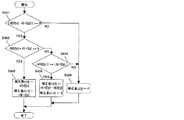
図5は歪み補正部108がフレーム0のラインyの撮影範囲のずれを補正する補正量c[0]と、フレーム0の代わりにフレーム−1のラインyを読み出す場合にその撮影範囲のずれを補正する補正量c[−1]を決定するフローチャートである。当該フローチャートに係わる処理は、CPU101がROM103に記憶されている制御プログラムを読み出し、次いでそれを実行することによって達成される。まず、ステップS501で撮影中のフレーム0のラインyの動き量d[0][y]と1つ前のフレーム−1のラインyの動き量d[−1][y]の変化(差)が、撮像センサの水平画素数W未満であるか判別する。変化がW以上である場合、補正限界を超えているためステップS506でフレーム0の補正量c[0]を0とする。この場合、フレーム−1は補正に用いないため、フレーム−1の補正量c[−1]には何も設定しない。変化がW未満であれば、ステップS502でフレーム0のラインyの動き量d[0][y]とフレーム−1のラインyの動き量d[−1][y]の積が負であるかどうかを判別する。負であれば、フレーム0のライン0を基準として、フレーム0とフレーム−1のそれぞれのラインyの撮影範囲のずれが左右反対方向に向いているため、フレーム0の撮影範囲の不足部分(図4に示した斜線部)をフレーム−1の撮影範囲を用いて補正できる。そこで、ステップS503でフレーム0の補正量c[0]をフレーム0のラインyの動き量から−d[0][y]、フレーム−1の補正量c[−1]をフレーム−1のラインyの動き量から−d[−1][y]とする。一方、フレーム0とフレーム−1のラインyの動き量の積が正であれば、基準となるフレーム0のライン0に対して、フレーム0とフレーム−1のそれぞれのラインyの撮影範囲は同じ方向に偏っている。そのため、フレーム0の撮影範囲の不足部分はフレーム−1の撮影範囲を用いても完全には補正できない。そこで、ステップS504でフレーム0のラインyの動き量d[0][y]より、フレーム−1のラインyの動き量d[−1][y]が小さいかを判別する。フレーム−1の動き量が小さい場合、フレーム−1のほうが基準となる(フレーム0のライン0の)撮影範囲により近いため、フレーム0の不足している撮影範囲の一部を補正することができる。そこで、ステップS505でフレーム0の補正量c[0]をフレーム0とフレーム−1のラインyの動き量の差分から、d[0][y]−d[−1][y]とし、フレーム−1の補正量c[−1]を0とする。フレーム−1のほうが動き量が大きい場合、ステップS506でフレーム0の補正量c[0]を0とする。この場合、フレーム−1は補正に用いないため、フレーム−1の補正量c[−1]には何も設定しない。
FIG. 5 shows a correction amount c [0] for correcting the shift of the shooting range of the line y of the
なお、図5のステップS501ではライン毎に補正限界を超えているか判定しているが、同一フレームで補正限界を超えないラインと超えるラインが連続していた場合、それらの補正量が不連続になってしまう。そのため、動き検出部110が1フレーム前に比べて撮像センサの水平画素数を超える動きを検出した場合、歪み補正部108はそのフレーム全体に対して歪み補正を行わないように構成する。
In step S501 in FIG. 5, it is determined whether or not the correction limit is exceeded for each line. However, when the line that does not exceed the correction limit and the line that exceeds the limit are continuous in the same frame, the correction amount is discontinuous. turn into. Therefore, when the
図6は歪み補正部108がフレーム0の画素(x,y)の参照フレームfを決定するフローチャートである。まず、ステップS601でフレーム0の補正量c[0]を加えた画素の水平位置x+c[0]が、フレーム0のラインyの撮影範囲内かを判別する。撮影範囲内であれば、ステップS602で参照フレームfをフレーム0とする。このとき、フレーム0の画素(x+c[0],y)が読み出し元となる。すなわち、補正データとして読み出される。範囲外であれば、ステップS603で参照フレームfをフレーム−1とする。このとき、フレーム−1のラインyに対する補正量c[−1]は、その動き量からd[−1][y]とし、フレーム−1の画素(x+c[−1],y)が読み出し元となる。
FIG. 6 is a flowchart in which the
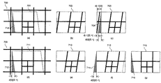
図7はビデオカメラ100が右方向に一定速度で動きながら被写体を撮影した画像に対して、歪み補正部108が歪み補正を行った例を示す。フレーム−1では(a)〜(b)に示すように、被写体700に対して701の範囲が撮影されて、撮影画像703がバッファメモリ107に格納される。また、フレーム0では(d)〜(e)に示すように、被写体700に対して711の範囲が撮影されて、撮影画像713がバッファメモリ107に格納される。撮影画像713に対してその先頭ラインを基準に歪みを補正するには、(f)に示すように破線で囲まれた領域を読み出す必要があるが、斜線部714が撮影画像713の範囲を超えている。この部分は(d)に示したフレーム0の撮影範囲711と接する斜線部712に対応しており、(a)に示したフレーム−1の撮影範囲701に斜線部712は含まれている。歪み補正部108は、図5〜6に示したフローチャートの処理によって、フレーム0の撮影画像713を超えた斜線部714の代わりに、(c)に示すようにフレーム−1の撮影画像703に含まれる斜線部704を読み出し元とする。その結果、(g)に示すように歪みを補正したフレーム0の出力画像715が、斜線部716を欠くことなく出力される。
FIG. 7 shows an example in which the
(f)に示した撮影画像713を超えた斜線部714は、各ラインe(=0〜E−1)の幅が各ラインeの動き量d[0][e]と等しく、右端で撮影画像713の左端と接している。(c)に示した撮影画像703の斜線部704は、各ラインe(=0〜E−1)の幅が斜線部714と等しく、左端は撮影画像703の左端から各ラインeの動き量d[−1][e]を空けた位置となっている。すなわち、フレーム0とフレーム−1の各ラインの動き量から、斜線部の位置と形状は決定される。
A hatched
図8はビデオカメラ100が左方向への動きから右方向への動きに徐々に変化しながら被写体を撮影した画像に対して、歪み補正部108が歪み補正を行った例を示す。フレーム−1では(a)〜(b)に示すように、被写体800に対して801の範囲が撮影されて、撮影画像803がバッファメモリ107に格納される。また、フレーム0では(d)〜(e)に示すように、被写体800に対して811の範囲が撮影されて、撮影画像813がバッファメモリ107に格納される。撮影画像813に対して先頭ラインを基準に歪みを補正するには、(f)に示すように破線で囲まれた領域を読み出す必要があるが、斜線部814が撮影画像813の範囲を超えている。この部分は(d)に示したフレーム0の撮影範囲811と接する斜線部812に対応しており、(a)に示したフレーム−1の撮影範囲801と斜線部812は多くの部分で重なっているが一部は重なっていない。歪み補正部108は、図5〜6に示したフローチャートの処理によって、フレーム0の撮影画像813を超えた斜線部814の代わりに、(c)に示すフレーム−1の撮影画像803と斜線部804の重なった領域を読み出し元とする。撮影画像803と斜線部804の重ならない領域があるため、歪み補正部はフレーム0の歪みを完全には補正せず、フレーム−1の撮影画像803を越えない範囲で各ラインの補正量を決定する。その結果、(g)に示すように可能な範囲で歪みを補正されたフレーム0の出力画像815が、斜線部816を欠くことなく出力される。
FIG. 8 shows an example in which the
(f)に示した撮影画像813を超えた斜線部814は、各ラインe(=0〜E−1)の幅が各ラインeの動き量d[0][e]と等しく、右端で撮影画像813の左端と接している。(c)に示した撮影画像803の斜線部804は、各ラインe(=0〜E−1)の幅が斜線部814と等しく、左端は撮影画像803の左端から各ラインeの動き量d[−1][e]を(正負の符号を考慮して)空けた位置となっている。図に示したラインYより前のラインでは、撮影画像803と斜線部804で重なっている領域がないため、(g)に示したフレーム0の出力画像815の対応する(ラインYより前の)部分は全く補正されない。ラインYより後のラインでは、撮影画像803と斜線部804の重なっている幅の量だけ、フレーム0の対応する(ラインYより後の)部分は補正される。すなわち、フレーム0とフレーム−1の各ラインの動き量から、斜線部の位置と形状は決定される。
The hatched portion 814 exceeding the captured
本実施例によれば、撮影画像に対して出力画像の画角を狭くしなくても、ローリングシャッタ方式の撮像センサによる撮像画像の歪みが補正できる。また、撮像センサに対して、例えば走査方向の入れ替えなどの構成を導入することなく、撮像画像の読み出し制御だけで撮影画像のローリングシャッタ歪を補正できる。 According to the present embodiment, it is possible to correct distortion of an image captured by a rolling shutter image sensor without reducing the angle of view of the output image relative to the captured image. In addition, the rolling shutter distortion of the captured image can be corrected only by the readout control of the captured image without introducing a configuration such as switching of the scanning direction for the imaging sensor.
第2の実施例
次に、本発明の第2の実施形態について説明する。
Second Example Next, a second embodiment of the present invention will be described.
本実施形態のビデオカメラは、図1のビデオカメラ100と同じ構成であるので、その説明は省略する。本実施形例においては、歪み補正部108は先頭ラインでなく中間ラインを基準として、同一フレームの他のラインの撮影範囲のずれを補正する。
Since the video camera of this embodiment has the same configuration as the
基準とする中間ラインE/2の出力タイミングを0として、動き検出部110の検出結果から、フレーム0の任意のラインeの出力時の動き量d[0][e]は求められる。例えば、フレーム0の先頭ライン0の出力時の動き量はd[0][0]、終端ラインE−1の出力時の動き量はd[0][E−1]である。
The motion amount d [0] [e] at the time of outputting an arbitrary line e in
バッファメモリ107には撮影中のフレーム1と1つ前のフレーム0と2つ前のフレーム−1の撮影画像データが格納されており、歪み補正部108はフレーム0に対して歪み補正を行う。歪み補正部108は中間ラインE/2を基準として、同一フレームの他のラインの撮影範囲のずれを補正する。ビデオカメラ100の動きが水平かつ同一方向であれば、中間ラインE/2より後のラインのずれを補正する際には、第1の実施形態と同様に撮影範囲を超える過去の撮影範囲が必要となる。一方、中間ラインE/2より前のラインのずれを補正する際に、それらの撮影範囲を超える未来の撮影範囲が必要となる。
The
このため、歪み補正部108は、中間ラインE/2より後のラインに対しては、第1の実施例で説明した図5と図6のフローチャートと同じ処理を行い、フレーム0の撮影範囲を超えた部分はフレーム−1を代わりの読み出し元として用いる。また、中間ラインE/2より前のラインに対しては、図5と図6のフローチャートに示した処理に対して、フレーム0の撮影範囲を超えた部分をフレーム−1ではなくフレーム1を代わりの読み出し元として用いるよう変更した処理を行う。
For this reason, the
図9はビデオカメラ100が右方向に一定速度で動きながら被写体を撮影した画像に対して、歪み補正部108が歪み補正を行った例を示す。(a)(b)(c)に連続するフレーム−1の撮影画像903、フレーム0の撮影画像913、フレーム1の撮影画像923をそれぞれ示す。(b)に示すフレーム0の撮影画像913に対して中間ラインE/2を基準に歪みを補正するには、破線で囲まれた領域を読み出す必要があるが、斜線部914と斜線部915が撮影画像913の範囲を超えている。斜線部914は(a)に示したフレーム−1の撮影画像903に含まれる斜線部904に、斜線部915は(c)に示したフレーム1の撮影画像923に含まれる斜線部925にそれぞれ対応する。歪み補正部108は、フレーム0の斜線部914と斜線部915の代わりに、それらの領域904、925を読み出し元とする。すなわち、補正データとして使用する。その結果、(d)に示すように歪みを補正したフレーム0の出力画像916が、斜線部917と斜線部918を欠くことなく出力される。なお、斜線部の位置と形状は、フレーム−1の中間ラインより後の各ラインと、フレーム0の各ラインと、フレーム1の中間ラインより前の各ラインの動き量から決定される。
FIG. 9 shows an example in which the
本実施例によれば、第1の実施例に比べて、画像中心部については撮影画像がそのまま用いられるため、補正の影響を目立たなくすることができる。 According to the present embodiment, compared with the first embodiment, the photographed image is used as it is at the center of the image, so that the influence of correction can be made inconspicuous.
第3の実施例
次に、本発明の第3の実施例について説明する。
本実施例のビデオカメラも、図1のビデオカメラ100と同じ構成であるため、その説明を省略する。
Third Embodiment Next, a third embodiment of the present invention will be described.
Since the video camera of this embodiment also has the same configuration as the
本実施例においては、歪み補正部108は補正するフレームの撮影範囲の境界近傍にある画素に対して、そのフレームから読み出した画素と、補正に用いる前後に撮影されたフレームから読み出した画素とを、境界からの距離に応じた比率で合成する補正を行う。
In the present embodiment, the
例えば、フレーム0を補正対象とし、その撮影範囲の不足部分をフレーム−1の撮影範囲で補う場合、フレーム0の撮影範囲の境界から数画素を、フレーム−1のそれらと同じ撮影範囲の数画素と合成して読み出す。例えば、境界から順にフレーム0の5画素を10%、25%、50%、75%、90%、同じ撮影位置のフレーム−1の5画素を90%、75%、50%、25%、10%の重み付けで合成する。
For example, when
本実施例によれば、第1及び第2の実施例に比べて、前後のフレームを参照して補った画像部分においてつなぎ目を目立たなくすることが出来る。 According to the present embodiment, compared to the first and second embodiments, the joints can be made inconspicuous in the image portion supplemented by referring to the preceding and following frames.
以上説明した第1〜3の実施例では、読み出し元(参照フレームから読み出される画素)を特定ラインの特定位置として説明している。しかしこれに限らず、より良好な画質を得るためには、読み出し位置の周辺ライン・周辺画素に対してフィルタ演算を行って補正画素データ(出力画像)を生成してもよい。この場合、フィルタ演算の参照領域がフレームの撮影範囲を跨いでしまうときは、フレームを跨いで参照領域を設定するよう構成すればよい。 In the first to third embodiments described above, the reading source (pixels read from the reference frame) is described as the specific position of the specific line. However, the present invention is not limited to this, and in order to obtain better image quality, correction pixel data (output image) may be generated by performing a filter operation on the peripheral lines and peripheral pixels at the readout position. In this case, when the reference area for the filter operation straddles the imaging range of the frame, the reference area may be set across the frame.
さらに、上述した第1〜3の実施例では、読み出し位置が撮影範囲を超えた場合、常に前後のフレームを用いて補正を行っている。これについても、動き検出部110が検出した動きがビデオカメラ100のパンニングであると判定された場合のみ、第1〜3の実施例の補正を行うよう構成しても良い。
Further, in the first to third embodiments described above, when the reading position exceeds the shooting range, correction is always performed using the previous and next frames. Also in this regard, the correction of the first to third embodiments may be performed only when it is determined that the motion detected by the
上述した第1〜3実施例においては、ビデオカメラの水平方向の動きによる撮影画像の歪の補正構成として本件発明を説明したが、次に垂直方向のビデオカメラの動きによる撮影画像の歪の補正構成として本件発明の実施例を説明する。以下の実施例においても、ビデオカメラ100の構成は上記第1〜3実施例と同じであるので、その説明は省略する。
In the first to third embodiments described above, the present invention has been described as a configuration for correcting distortion of a captured image due to horizontal movement of the video camera. Next, correction of distortion of a captured image due to movement of the video camera in the vertical direction will be described. An embodiment of the present invention will be described as a configuration. Also in the following embodiments, the configuration of the
第4実施例
図10はビデオカメラ100が上方向に動いた場合に(チルティング)、動き検出部110が時間経過(横軸)に対して検出した垂直方向の動き量(縦軸)の例を示す。動き検出部110は撮像センサ105から1フレーム分の画像信号が出力される期間に、複数回(図中の黒丸部分)垂直方向の動き量dを検出する。ここで、動き量dはフレーム0のライン0の撮影時刻を基準として、それに対する各ラインの撮影時刻における相対位置を下方向を正とする符号付きで表す。フレーム0の任意のラインeの出力時の動き量d[0][e]は、上記複数の検出結果を用いた補間から求められる。例えば、フレーム0の有効画像の終端ラインE−1の出力時の動き量はd[0][E−1]となる。
Fourth Embodiment FIG. 10 shows an example of a vertical motion amount (vertical axis) detected by the
図11はビデオカメラ100が上方向に動いた場合の、時間経過(横軸)に対する各ラインの撮影位置の例を示す。縦に8、横に16並んでいる実線で区切られた矩形領域は、撮像センサの各ラインが、時間経過に対してどのように動いているかを示している。ここでは図を単純化するために、有効画像のライン数E=6、垂直ブランキングのライン数B=2、合計のライン数を8として図示している。左から8列分がフレーム−1を撮影している期間であって、中央から右に8列分がフレーム0を撮影している期間を示す。太線で区切られた矩形領域は、その時刻に撮影されているラインであることを示す。また、図の上下方向は撮影画像の最上部からの距離に対応し、隣接する太線矩形領域が上下方向で一部重なっているのはチルティングによるカメラの上方向の動きによる。したがって、チルティング下で得られる撮影画像(太線領域1111〜1116)は、矩形領域1111〜1120に対応する画像より画像の垂直方向において狭い範囲の画像となる。この撮影画像がEラインの1フレームの画像として記憶された場合、図13の画像1303のように垂直方向に引き伸ばされた画像になる。例えば、左端の上端にある太線で区切られた矩形領域1101は、フレーム−1のライン0がこの時刻に撮影されることを示す。その右隣下の矩形領域1102は、上方向のチルティングにより移動したフレーム−1において、ライン1が次に撮影されることを示す。
FIG. 11 shows an example of the shooting position of each line with respect to time (horizontal axis) when the
バッファメモリ107には撮影中のフレーム0と1つ前のフレーム−1の撮影画像データが格納される。図中の太線で区切られた矩形領域1101〜1108、1111〜1118のうち、有効画像の範囲である1101〜1106、1111〜1116が、それらのフレームの各ラインの撮影位置を示している。ライン毎に撮像のタイムラグがあるため、撮影位置は垂直方向に徐々にずれている。フレーム0のライン0の撮影時刻におけるフレーム0のライン0の垂直位置を0とすると、同一時刻におけるラインE−1(矩形領域1120)の位置はH((E−1)/E)であるが、ラインE−1の撮影時刻ではH((E−1)/E)+d[0][E−1]となる。ここで、Hは撮像センサの有効画像のライン数であり、垂直位置は下方向を正とする符号付きで表される。
The
歪み補正部108は所定のライン(本実施例ではライン0)を基準として、上述のように動き量dを用いて同一フレームの他のラインの撮影位置のずれを補正する。図11の例では、ビデオカメラ100の動きが垂直であるため、歪み補正部108は出力画像のラインに対して、垂直方向にずらした撮影画像のラインを読み出すことで補正を行う。例えば、出力画像のラインE−2を出力する場合、基準時刻におけるフレーム0のラインE−2は矩形領域1119の位置H((E−2)/E)にある。これはラインE−1の撮影時刻におけるラインE−1の矩形領域1116と同じ垂直位置H((E−1)/E)+d[0][E−1]であるため、ラインE−2の代わりにラインE−1を読み出すことで補正を行うことができる。すなわち、基準としたライン0の撮影時刻に対応する位置でのライン2〜E−1の画像を得ることができる。ここでは説明を単純にするため、撮影画像と出力画像の倍率を等倍としている。なお、垂直位置の全く同じラインが撮影画像になくても、その周辺のラインを読み出して補間処理を行うことで出力画像のラインを得ることができる。
The
しかし、出力画像のラインE−1を出力する場合、基準時刻におけるフレーム0のラインE−1は矩形領域1120(斜線部)の位置にあり、フレーム0の有効画像1111〜1116の撮影範囲を超えている。本図のように、1つ前のフレーム−1からフレーム0にかけてビデオカメラ100の動きが同一方向であれば、斜線部は過去のフレームでの撮影範囲であるため、1つ前のフレーム−1を代わりの読み出し元として用いる。例えば、矩形領域1120の垂直位置は、フレーム−1のラインE−2の矩形領域1105と、ラインE−1の矩形領域1106の間であり、それらを読み出して補間処理を行うことで、出力画像のラインE−1を得ることができる。
However, when the line E-1 of the output image is output, the line E-1 of the
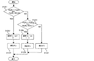
図12は歪み補正部108が出力画像のフレーム0のラインyを出力する際に、読み出し元となる撮影画像のフレームfと補正のオンオフを決定するフローチャートである。本フローチャートによる処理も、ROM103に記憶されている制御プログラムをCPU101が読み出して実行することにより達成される。まず、ステップS1201において、Top(0)はフレーム0で撮影位置が最も上であったラインの撮影位置を示し、Btm(0)はフレーム0で撮影位置が最も下であったラインの撮影位置を示す。ビデオカメラ100の垂直方向の動きが、撮像センサの垂直走査の速度より遅ければ、Top(0)はフレーム0のライン0の撮影位置であって、Btm(0)はフレーム0のラインE−1の撮影位置となる。基準時刻でのフレーム0のラインyの垂直位置はH(y/E)であって、これがフレーム0の撮影範囲であるTop(0)とBtm(0)の間に収まっている(YES)かを判定する。収まっている場合には、ステップS1202において参照フレームfを0とし、ステップS1205で補正をオンにして処理を終了する。ステップS501でフレーム0の撮影範囲に収まっていない(NOの)場合、ステップS1203でH(y/E)がフレーム−1の撮影範囲であるTop(−1)とBtm(−1)の間に収まっているかを判定する。収まっている(YESの)場合には、ステップS1204において参照フレームfを−1とし、ステップS506で補正をオンにして処理を終了する。ステップS1203でフレーム−1の撮影範囲にも収まっていない(NOの)場合には、補正限界を超えているため、ステップS1207で補正をオフにして処理を終了する。
FIG. 12 is a flowchart for determining the frame f of the captured image that is the reading source and the on / off of the correction when the
なお、図12のステップS1203ではライン毎に補正限界を超えているか判定しているが、同一フレームで補正限界を超えないラインと超えるラインが連続していた場合、それらの補正量が不連続になってしまう。そのため、実際には基準時刻におけるフレーム0のライン0とラインE−1の垂直位置が、フレーム0とフレーム−1を足し合わせた撮影範囲に含まれているかを予め判定しておく。即ち、0とH(E−1/E)が、Top(0)からBtm(0)と、Top(−1)からBtm(−1)を足し合わせた範囲に含まれているかを判定する。含まれていない場合には、フレーム全体に対する補正をオフとする。これは、例えばフレーム−1からフレーム0の途中までビデオカメラ100が下方向に動き、フレーム0の途中からビデオカメラ100が上方向に反転して動いた場合などが該当する。この場合、基準時刻でのフレーム0のラインE−1の垂直位置がいずれのフレームでも撮影されておらず、補正限界を超えていると判定される。
Note that in step S1203 of FIG. 12, it is determined whether the correction limit is exceeded for each line. However, if the line that does not exceed the correction limit and the line that exceeds the limit are continuous in the same frame, their correction amounts are discontinuous. turn into. Therefore, it is determined in advance whether the vertical position of the
また、図12のステップS1204で参照フレームが−1となった場合でも、周辺のラインとして補間処理に利用できるラインがフレーム0に存在する場合には、フレーム−1とフレーム0のラインから補間処理を行うこともできる。例えば、図11では基準時刻にフレーム0のラインE−1が矩形領域1120(斜線部)の位置にあったため、近傍の2ラインで線形補間する場合には、フレーム−1のラインE−2の矩形領域1105と、ラインE−1の矩形領域1106を利用することになる。これに対して、矩形領域1105よりも、フレーム0のラインE−1の矩形領域1116がより近傍に位置していれば、これとフレーム−1のラインE−1の矩形領域1106の2ラインから線形補間することができる。
In addition, even when the reference frame becomes −1 in step S1204 in FIG. 12, if there is a line that can be used for the interpolation process as a peripheral line in
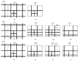
図13はビデオカメラ100が上方向に一定速度で動きながら被写体を撮影した画像に対して、歪み補正部108が歪み補正を行った例を示す。フレーム−1では(a)〜(b)に示すように、被写体1300に対して1301の範囲が撮影されて、縦に伸びた撮影画像1303がバッファメモリ107に格納される。また、フレーム0では(d)〜(e)に示すように、被写体1300に対して611の範囲が撮影されて、縦に伸びた撮影画像1313がバッファメモリ107に格納される。撮影画像1313に対して先頭ラインを基準に歪みを補正するには、(f)に示すように破線で囲まれた領域を読み出して縦に縮める必要があるが、斜線部1314が撮影画像1313の範囲を超えている。この部分は(d)に示したフレーム0の撮影範囲1311と接する斜線部1312に対応しており、(a)に示したフレーム−1の撮影範囲1301に斜線部1312は含まれている。歪み補正部108は、図12に示したフローチャートの処理によって、フレーム0の撮影画像1313を超えた斜線部1314の代わりに、(c)に示すようにフレーム−1の撮影画像1303に含まれる斜線部1304を読み出し元とする。その結果、(g)に示すように歪みを補正したフレーム0の出力画像1315が、斜線部1316を欠くことなく出力される。
FIG. 13 shows an example in which the
このように上方向へのチルティングに対しては、フレーム0だけでなくフレーム−1を読み出し元(参照フレーム)として用いることで歪みを補正する。 In this way, for upward tilting, distortion is corrected by using not only frame 0 but also frame -1 as a reading source (reference frame).
図14はビデオカメラ100が下方向に一定速度で動きながら被写体を撮影した画像に対して、歪み補正部108が歪み補正を行った例を示す。フレーム0で(a)〜(b)に示すように、被写体1400に対して1401の範囲が撮影されて、縦に縮んだ撮影画像1403がバッファメモリ107に格納される。撮影画像1403に対して先頭ラインを基準に歪みを補正するには、(c)に示すように破線で囲まれた領域を読み出して縦に伸ばす必要がある。上方向へのチルティングの場合に対して、読み出し範囲が撮影画像1403に包含されていて、斜線部1404が余っている。この部分は(a)に示したフレーム0の撮影範囲1401に含まれる斜線部1402に対応している。歪み補正部108は、図12に示したフローチャートの処理によって、フレーム0の撮影画像1403のみを読み出し元として、(d)に示すように歪みを補正したフレーム0の出力画像1405を出力する。
FIG. 14 shows an example in which the
このようにビデオカメラの下方向へのチルティングに対しては、フレーム0だけで歪みを補正する。
Thus, for tilting the video camera downward, the distortion is corrected only by
以上説明した本件発明の第4の実施例によれば、撮影画像に対して出力画像の画角を狭くしなくても、ローリングシャッタ方式の撮像センサによる撮影画像の歪みが補正できる。また、撮像センサに対して、例えば走査方向の入れ替えなどの構成を導入することなく、撮像画像の読み出し制御だけで撮影画像のローリングシャッタ歪を補正できる。 According to the fourth embodiment of the present invention described above, distortion of a captured image by a rolling shutter type image sensor can be corrected without narrowing the angle of view of the output image with respect to the captured image. In addition, the rolling shutter distortion of the captured image can be corrected only by the readout control of the captured image without introducing a configuration such as switching of the scanning direction for the imaging sensor.
第5の実施形態
次に、本発明の第5の実施形態について説明する。
本実施例においては、歪み補正部108は先頭ラインでなく中間ラインを基準として、同一フレームの他のラインの撮影範囲のずれを補正する。
Fifth Embodiment Next, a fifth embodiment of the present invention will be described.
In the present embodiment, the
基準とする中間ラインE/2の出力タイミングを0として、動き検出部110の検出結果から、フレーム0の任意のラインeの出力時の動き量d[0][e]は求められる。例えば、フレーム0の先頭ライン0の出力時の動き量はd[0][0]、終端ラインE−1の出力時の動き量はd[0][E−1]となる。
The motion amount d [0] [e] at the time of outputting an arbitrary line e in
バッファメモリ107には撮影中のフレーム1と1つ前のフレーム0と2つ前のフレーム−1の撮影画像データが格納されており、歪み補正部108はフレーム0に対して歪み補正を行う。歪み補正部108は中間ラインE/2を基準として、同一フレームの他のラインの撮影位置のずれを補正する。ビデオカメラ100の動きが垂直かつ上方向であれば、中間ラインE/2より後で撮影範囲を超えるラインを補正する際には、第4の実施形態と同様に過去の撮影範囲が必要となる。一方、中間ラインE/2より前で撮影範囲を超えるラインを補正する際には、未来の撮影範囲が必要となる。
The
このため、歪み補正部108は、中間ラインE/2より後のラインに対しては、第4の実施例で説明した図12のフローチャートと同じ処理を行い、フレーム0の撮影範囲を超えた部分はフレーム−1を代わりの読み出し元として用いる。また、中間ラインE/2より前のラインに対しては、図12のフローチャートに示した処理に対して、フレーム0の撮影範囲を超えた部分をフレーム−1ではなくフレーム1を代わりの読み出し元として用いるよう変更した処理を行う。
For this reason, the
図15はビデオカメラ100が上方向に一定速度で動きながら被写体を撮影した画像に対して、歪み補正部108が歪み補正を行った例を示す。(a)(b)(c)に連続するフレーム−1の撮影画像1504、フレーム0の撮影画像1514、フレーム1の撮影画像1524をそれぞれ示す。フレーム0の撮影画像1514に対して中間ラインE/2を基準に歪みを補正するには、破線で囲まれた領域を読み出す必要があるが、斜線部1515と斜線部1516が撮影画像1514の範囲を超えている。斜線部1516は(a)に示したフレーム−1の撮影画像1504に含まれる斜線部1506に、斜線部1515は(c)に示したフレーム1の撮影画像1524に含まれる斜線部1525にそれぞれ対応する。歪み補正部108は、フレーム0の斜線部1515と斜線部1516の代わりに、それらの領域を読み出し元とする。その結果、(d)に示すように歪みを補正したフレーム0の出力画像1517が、斜線部1518と斜線部1519を欠くことなく出力される。
FIG. 15 shows an example in which the
なお、下方向へのチルティングに対しては、第4の実施例と同様に、フレーム0だけで歪みを補正する。
For downward tilting, as in the fourth embodiment, distortion is corrected using
本実施形態のビデオカメラ100は第4の実施例のビデオカメラに比べ、画像中心部は撮影画像がそのまま用いられるため、撮影画像において補正の影響を目立たなくすることができる。
Compared with the video camera of the fourth example, the
以上説明した第4〜5の実施例においても、読み出し元(参照フレームから読み出される画素)を特定ラインの特定位置として説明している。しかし、より良好な画質を得るためには、読み出し位置の周辺ライン・周辺画素に対してフィルタ演算を行って補正画素データ(出力画像)を生成してもよい。この場合、フィルタ演算の参照領域がフレームの撮影範囲を跨いでしまうときは、フレームを跨いで参照領域を設定するよう構成すればよい。 In the fourth to fifth embodiments described above, the reading source (pixels read from the reference frame) is described as the specific position of the specific line. However, in order to obtain better image quality, correction pixel data (output image) may be generated by performing a filter operation on the peripheral line and peripheral pixels at the readout position. In this case, when the reference area for the filter operation straddles the imaging range of the frame, the reference area may be set across the frame.
さらに、上述した第4〜5の実施例では、読み出し位置が撮影範囲を超えた場合、常に前後のフレームを用いて補正を行っている。これについても、動き検出部110が検出した動きがビデオカメラ100のチルティングであると判定された場合のみ、第4〜5の実施例の補正を行うよう構成しても良い。
Furthermore, in the fourth to fifth embodiments described above, when the reading position exceeds the shooting range, correction is always performed using the previous and next frames. Also in this regard, the correction of the fourth to fifth embodiments may be performed only when it is determined that the motion detected by the
第4〜5の実施形態では、読み出し位置が撮影範囲を超えた場合、常に前後のフレームを用いて補正を行っているが、動き検出部110の検出結果によりビデオカメラ100がチルティングしていると判定された場合のみ、補正を行うよう構成しても良い。
In the fourth to fifth embodiments, when the readout position exceeds the shooting range, correction is always performed using the previous and next frames, but the
上述した実施例においては、図5〜6及び図12に示した各処理は、各処理の機能を実現する為の制御プログラムをメモリ(ROM103)から読み出してCPU101が実行することによりその機能を実現させるものである。しかし、これに限定されるものではなく、図5〜6及び図12に示した各処理の全部または一部の機能を専用のハードウェアにより実現してもよい。また、上述したメモリは、光磁気ディスク装置、フラッシュメモリ等の不揮発性のメモリや、CD−ROM等の読み出しのみが可能な記録媒体より構成されてもよい。さらには、それら媒体の組合せによるコンピュータ読み取り、書き込み可能な記録媒体より構成されてもよい。
In the embodiment described above, each process shown in FIGS. 5 to 6 and FIG. 12 is realized by reading a control program for realizing the function of each process from the memory (ROM 103) and executing it by the
また、「コンピュータ読み取り可能な記録媒体」とは、フレキシブルディスク、光磁気ディスク、ROM、CD−ROM等の可搬媒体、コンピュータシステムに内蔵されるハードディスク等の記憶装置のことをいう。 The “computer-readable recording medium” refers to a storage device such as a flexible medium, a magneto-optical disk, a portable medium such as a ROM and a CD-ROM, and a hard disk incorporated in a computer system.
また、上記プログラムは、このプログラムを記憶装置等に格納したコンピュータシステムから、伝送媒体を介して、あるいは、伝送媒体中の伝送波により他のコンピュータシステムに伝送されてもよい。ここで、プログラムを伝送する「伝送媒体」は、インターネット等のネットワーク(通信網)や電話回線等の通信回線(通信線)のように情報を伝送する機能を有する媒体のことをいう。この場合、プログラムが送信された場合のサーバやクライアントとなるコンピュータシステム内部の揮発メモリ(RAM)のように、一定時間プログラムを保持しているものも「コンピュータ読み取り可能な記録媒体」に含むものとする。 The program may be transmitted from a computer system storing the program in a storage device or the like to another computer system via a transmission medium or by a transmission wave in the transmission medium. Here, the “transmission medium” for transmitting the program refers to a medium having a function of transmitting information, such as a network (communication network) such as the Internet or a communication line (communication line) such as a telephone line. In this case, a “computer-readable recording medium” includes a program that holds the program for a certain period of time, such as a volatile memory (RAM) inside a computer system that becomes a server or a client when the program is transmitted.
また、上記プログラムは、前述した機能の一部を実現する為のものであっても良い。さらに、前述した機能をコンピュータシステムに既に記録されているプログラムとの組合せで実現できるもの、いわゆる差分ファイル(差分プログラム)であっても良い。 The program may be for realizing a part of the functions described above. Furthermore, what can implement | achieve the function mentioned above in combination with the program already recorded on the computer system, and what is called a difference file (difference program) may be sufficient.
また、上記のプログラムを記録したコンピュータ読み取り可能な記録媒体等のプログラムプロダクトも本発明の実施形態として適用することができる。上記のプログラム、記録媒体、伝送媒体およびプログラムプロダクトは、本発明の範疇に含まれる。 A program product such as a computer-readable recording medium in which the above program is recorded can also be applied as an embodiment of the present invention. The above program, recording medium, transmission medium, and program product are included in the scope of the present invention.
以上、この発明の実施形態について図面を参照して詳述してきたが、具体的な構成はこの実施形態に限られるものではなく、この発明の要旨を逸脱しない範囲の設計等も含まれる。 The embodiment of the present invention has been described in detail with reference to the drawings. However, the specific configuration is not limited to this embodiment, and includes designs and the like that do not depart from the gist of the present invention.
Claims (10)
前記補正手段は、前記撮影画像の所定のフレームの各ラインの撮影時刻における動き量に基づいて、出力する画像の各ラインの画素を前記所定のフレームのどこから読み出すかを決定し、決定された読み出し位置が前記所定のフレームの撮影範囲を超えている画素に対しては、前記所定のフレームの前後に撮影されたフレームから対応する画素を読み出すことで前記撮影画像を補正することを特徴とする撮像装置。 A photographing means for photographing multiple consecutive frames in a rolling shutter method, a storage unit for storing the captured images of a plurality of frames the shot, and movement detecting means for detecting a motion amount between frames, said storage means A correction unit that corrects the captured image stored in the output unit, and an output unit that outputs the image corrected by the correction unit,
The correction means determines where to read out the pixels of each line of the image to be output from the predetermined frame based on the amount of movement at the shooting time of each line of the predetermined frame of the captured image, and the determined readout For the pixel whose position exceeds the imaging range of the predetermined frame, the captured image is corrected by reading out the corresponding pixel from frames captured before and after the predetermined frame. apparatus.
前記決定された読み出し位置が前記所定のフレームの撮影範囲を超えている画素に対しては、前記所定のフレームの1つ前に撮影されたフレームから対応する画素を読み出すことを特徴とする請求項1または2に記載の撮像装置。 The correction means determines from where in the predetermined frame the pixel of each line of the output image is read based on the amount of movement at the shooting time of each line , based on the shooting time of the first line of the predetermined frame. Decide
The corresponding pixel is read out from a frame photographed immediately before the predetermined frame for a pixel whose determined reading position exceeds a photographing range of the predetermined frame. The imaging apparatus according to 1 or 2.
前記決定された読み出し位置が前記所定のフレームの撮影範囲を超えている画素に対しては、前記画素のラインが出力画像の中間ラインより前か後ろかに応じて、前記フレームの1つ前又は1つ後に撮影されたフレームから読み出すことを特徴とする請求項1または2に記載の撮像装置。 The correction means, based on the shooting time of the intermediate line of the predetermined frame, based on the motion amount at the photographing time of each line, a read or pixel of each line of the image to be the output from anywhere of the predetermined frame Decide
For pixels whose determined readout position exceeds the imaging range of the predetermined frame, one pixel before or after the frame, depending on whether the line of pixels is before or after the intermediate line of the output image The image pickup apparatus according to claim 1, wherein the image pickup apparatus reads out from a frame photographed one time later.
前記決定された読み出し位置が前記所定のフレームの撮影範囲の境界近傍にある画素に対しては、前記所定のフレームから読み出した画素と、前記所定のフレームの前後に撮影されたフレームから読み出した画素とを前記境界からの距離に応じた比率で合成し、前記所定のフレームの前後に撮影されたフレームからの画素の読み出し位置を、当該フレームの各ラインの撮影時刻における動き量から算出することを特徴とする請求項1または2に記載の撮像装置。 Said correction means, based on the motion amount at the photographing time of each line of the predetermined frame, the pixels of each line of the image to be the output to determine whether read from where the predetermined frame,
For pixels whose determined readout position is in the vicinity of the border of the photographing range of the predetermined frame, pixels read from the predetermined frame and pixels read from frames photographed before and after the predetermined frame Are calculated at a ratio according to the distance from the boundary, and the pixel readout position from the frames photographed before and after the predetermined frame is calculated from the amount of motion at the photographing time of each line of the frame. The imaging apparatus according to claim 1, wherein the imaging apparatus is characterized.
前記補正手段は前記装置本体がパンニングまたはチルティングしている場合のみ、前記検出された動き量に基づいて撮影画像を前記記憶手段からの読み出すことを特徴とする請求項1ないし6の何れか1項に記載の撮像装置。 Based on the amount of movement obtained by the detection continued multiple times, comprising a determination means for determining whether the apparatus body is panning or tilting,
The correction unit reads out a captured image from the storage unit based on the detected amount of motion only when the apparatus main body is panning or tilting. The imaging device according to item.
前記記憶手段に格納された撮影画像を補正する補正ステップと、前記補正ステップで補正された画像を出力する出力ステップとを備え、
前記補正ステップは、前記撮影画像の所定のフレームの各ラインの撮影時刻における動き量に基づいて、出力する画像の各ラインの画素を前記所定のフレームのどこから読み出すかを決定するステップと、
決定された読み出し位置が前記所定のフレームの撮影範囲を超えている画素に対しては、前記所定のフレームの前後に撮影されたフレームから対応する画素を読み出すことで前記撮影画像を補正することを特徴とする撮像装置の制御方法。 An imaging apparatus comprising: an imaging unit that continuously captures a plurality of frames by a rolling shutter method; a storage unit that stores captured images of the captured frames; and a motion detection unit that detects a motion amount between frames. Control method,
A correction step of correcting the captured image stored in the storage means , and an output step of outputting the image corrected in the correction step,
The step of correcting determines a pixel of each line of the image to be output from where the predetermined frame is read based on the amount of motion at the shooting time of each line of the predetermined frame of the captured image;
For a pixel whose determined read position exceeds the imaging range of the predetermined frame, the captured image is corrected by reading the corresponding pixel from frames captured before and after the predetermined frame. A control method for an imaging apparatus.
前記撮影画像の所定のフレームの各ラインの撮影時刻における動き量に基づいて、出力する画像の各ラインの画素を前記所定のフレームのどこから読み出すかを決定し、決定された読み出し位置が前記所定のフレームの撮影範囲を超えている画素に対しては、前記所定のフレームの前後に撮影されたフレームから対応する画素を読み出すように前記記憶手段に格納された撮影画像を補正する補正手段と、前記補正手段により補正された画像を出力する出力手段として機能させるためのプログラム。 An imaging apparatus comprising: a photographing unit that continuously photographs a plurality of frames by a rolling shutter method; a storage unit that stores photographed images of the plurality of frames that have been photographed; and a motion detection unit that detects a motion amount between the frames. In the device
Based on the amount of motion at the shooting time of each line of the predetermined frame of the captured image, it is determined from where in the predetermined frame the pixel of each line of the output image is read, and the determined read position is the predetermined Correction means for correcting a captured image stored in the storage means so as to read out corresponding pixels from frames photographed before and after the predetermined frame for pixels exceeding the photographing range of the frame; and A program for functioning as output means for outputting an image corrected by the correction means.
Priority Applications (2)
| Application Number | Priority Date | Filing Date | Title |
|---|---|---|---|
| JP2010174526A JP5548552B2 (en) | 2010-08-03 | 2010-08-03 | Imaging device |
| US13/178,713 US8462219B2 (en) | 2010-08-03 | 2011-07-08 | Image pickup apparatus and image processing method of a picked-up image |
Applications Claiming Priority (1)
| Application Number | Priority Date | Filing Date | Title |
|---|---|---|---|
| JP2010174526A JP5548552B2 (en) | 2010-08-03 | 2010-08-03 | Imaging device |
Publications (3)
| Publication Number | Publication Date |
|---|---|
| JP2012039177A JP2012039177A (en) | 2012-02-23 |
| JP2012039177A5 JP2012039177A5 (en) | 2013-08-15 |
| JP5548552B2 true JP5548552B2 (en) | 2014-07-16 |
Family
ID=45555885
Family Applications (1)
| Application Number | Title | Priority Date | Filing Date |
|---|---|---|---|
| JP2010174526A Expired - Fee Related JP5548552B2 (en) | 2010-08-03 | 2010-08-03 | Imaging device |
Country Status (2)
| Country | Link |
|---|---|
| US (1) | US8462219B2 (en) |
| JP (1) | JP5548552B2 (en) |
Families Citing this family (17)
| Publication number | Priority date | Publication date | Assignee | Title |
|---|---|---|---|---|
| JP5734082B2 (en) * | 2011-05-11 | 2015-06-10 | キヤノン株式会社 | Imaging apparatus, control method therefor, and program |
| KR101856947B1 (en) | 2011-10-07 | 2018-05-11 | 삼성전자주식회사 | Photographing apparatus, motion estimation apparatus, method for image compensation, method for motion estimation, computer-readable recording medium |
| JP5794705B2 (en) * | 2013-02-01 | 2015-10-14 | キヤノン株式会社 | Imaging apparatus, control method thereof, and program |
| KR102003460B1 (en) | 2013-08-27 | 2019-07-24 | 한화테크윈 주식회사 | Device and Method for dewobbling |
| KR101627795B1 (en) * | 2014-12-24 | 2016-06-08 | 전자부품연구원 | Method for Rolling Shutter Correction with Key-Frame and Gyroscope and Photographing Apparatus using the same |
| KR101668680B1 (en) * | 2015-05-08 | 2016-10-24 | (주)이즈미디어 | Method and apparatus for image capture |
| JP2017038281A (en) * | 2015-08-11 | 2017-02-16 | キヤノン株式会社 | Imaging device and control method therefor |
| JP6882083B2 (en) * | 2017-06-07 | 2021-06-02 | キヤノン株式会社 | Image processing device, image forming device, image processing method and program |
| US10810751B2 (en) * | 2017-06-23 | 2020-10-20 | Panasonic Intellectual Property Corporation Of America | Distance measuring apparatus and distance measuring method |
| JP6956031B2 (en) * | 2017-06-23 | 2021-10-27 | パナソニック インテレクチュアル プロパティ コーポレーション オブ アメリカPanasonic Intellectual Property Corporation of America | Distance measuring device and distance measuring method |
| JP2019054360A (en) * | 2017-09-14 | 2019-04-04 | セイコーエプソン株式会社 | Electronic device, motion sensor, position change detection program, and position change detection method |
| CN110651299A (en) * | 2018-02-28 | 2020-01-03 | 深圳市大疆创新科技有限公司 | Image water ripple detection method and device, unmanned aerial vehicle and storage device |
| US20200137336A1 (en) * | 2018-10-30 | 2020-04-30 | Bae Systems Information And Electronic Systems Integration Inc. | Interlace image sensor for low-light-level imaging |
| CN114390188B (en) * | 2020-10-22 | 2023-05-12 | 华为技术有限公司 | Image processing method and electronic equipment |
| US12335594B2 (en) * | 2021-10-21 | 2025-06-17 | Raytheon Company | Single camera time-delay to enforce data transmission compliance in real and near real time video |
| JP2024093375A (en) * | 2022-12-27 | 2024-07-09 | 浜松ホトニクス株式会社 | Sample observation device and sample observation method |
| US12470605B2 (en) | 2023-04-19 | 2025-11-11 | Raytheon Company | Enforcement of offline and real time data capture and transmission compliance using a ground truth map (GTM) |
Family Cites Families (21)
| Publication number | Priority date | Publication date | Assignee | Title |
|---|---|---|---|---|
| JP3925415B2 (en) * | 2003-01-22 | 2007-06-06 | ソニー株式会社 | Image processing apparatus and method, recording medium, and program |
| JP3804617B2 (en) * | 2003-02-14 | 2006-08-02 | コニカミノルタフォトイメージング株式会社 | Image processing apparatus and method |
| US7499081B2 (en) * | 2003-04-30 | 2009-03-03 | Hewlett-Packard Development Company, L.P. | Digital video imaging devices and methods of processing image data of different moments in time |
| JP2005077886A (en) * | 2003-09-02 | 2005-03-24 | Canon Inc | Imaging device |
| JP3829843B2 (en) * | 2003-12-08 | 2006-10-04 | ソニー株式会社 | Image processing device |
| JP4389779B2 (en) * | 2004-12-27 | 2009-12-24 | ソニー株式会社 | Method for correcting distortion of captured image signal and distortion correction apparatus for captured image signal |
| JP4390274B2 (en) * | 2004-12-27 | 2009-12-24 | キヤノン株式会社 | Imaging apparatus and control method |
| JP4390068B2 (en) | 2004-12-28 | 2009-12-24 | ソニー株式会社 | Method for correcting distortion of captured image signal and distortion correction apparatus for captured image signal |
| US7656428B2 (en) * | 2005-05-05 | 2010-02-02 | Avago Technologies General Ip (Singapore) Pte. Ltd. | Imaging device employing optical motion sensor as gyroscope |
| US7728909B2 (en) * | 2005-06-13 | 2010-06-01 | Seiko Epson Corporation | Method and system for estimating motion and compensating for perceived motion blur in digital video |
| JP2007020045A (en) | 2005-07-11 | 2007-01-25 | Sanyo Electric Co Ltd | Electronic camera |
| JP4446193B2 (en) * | 2005-11-11 | 2010-04-07 | ソニー株式会社 | Image processing apparatus and method, and program |
| JP4509917B2 (en) * | 2005-11-21 | 2010-07-21 | 株式会社メガチップス | Image processing apparatus and camera system |
| US8503817B2 (en) * | 2006-03-01 | 2013-08-06 | Panasonic Corporation | Apparatus, method and imaging apparatus for correcting distortion of image data using interpolation |
| JP4743007B2 (en) * | 2006-06-16 | 2011-08-10 | ソニー株式会社 | Image processing apparatus, image processing method, recording medium, and program |
| JP4268220B2 (en) * | 2007-08-03 | 2009-05-27 | パナソニック株式会社 | Imaging apparatus, imaging method, and program |
| JP2009141717A (en) * | 2007-12-07 | 2009-06-25 | Hitachi Ltd | Imaging device |
| US8253812B2 (en) * | 2008-02-23 | 2012-08-28 | Sanyo Electric Co., Ltd. | Video camera which adopts a focal-plane electronic shutter system |
| US8223236B2 (en) * | 2008-07-03 | 2012-07-17 | Sony Ericsson Mobile Communications Ab | Apparatus and method for image recording |
| JP2010136302A (en) * | 2008-12-08 | 2010-06-17 | Sony Corp | Imaging apparatus, imaging method and program |
| JP5778469B2 (en) * | 2011-04-28 | 2015-09-16 | 日本アビオニクス株式会社 | Imaging apparatus, image generation method, infrared camera system, and interchangeable lens system |
-
2010
- 2010-08-03 JP JP2010174526A patent/JP5548552B2/en not_active Expired - Fee Related
-
2011
- 2011-07-08 US US13/178,713 patent/US8462219B2/en not_active Expired - Fee Related
Also Published As
| Publication number | Publication date |
|---|---|
| JP2012039177A (en) | 2012-02-23 |
| US20120033098A1 (en) | 2012-02-09 |
| US8462219B2 (en) | 2013-06-11 |
Similar Documents
| Publication | Publication Date | Title |
|---|---|---|
| JP5548552B2 (en) | Imaging device | |
| JP4662880B2 (en) | Imaging apparatus and imaging method | |
| JP5794705B2 (en) | Imaging apparatus, control method thereof, and program | |
| JP4446193B2 (en) | Image processing apparatus and method, and program | |
| JP6385212B2 (en) | Image processing apparatus and method, imaging apparatus, and image generation apparatus | |
| TWI467313B (en) | Image processing device, image processing method, and recording medium | |
| JP5572700B2 (en) | Imaging apparatus and imaging method | |
| JP6752685B2 (en) | Imaging equipment, imaging methods and programs | |
| JP4435228B2 (en) | Imaging apparatus and control method thereof | |
| JP6786311B2 (en) | Image processing equipment, image processing methods, computer programs and storage media | |
| JP6789682B2 (en) | Imaging device, its control method, and program | |
| JP2021185689A (en) | Imaging equipment, programs, recording media, and control methods | |
| JP2009135713A (en) | Method and apparatus for correcting image distortion caused by camera shake | |
| JP7672809B2 (en) | Imaging device, imaging method, program, and recording medium | |
| JP6961423B2 (en) | Image processing equipment, imaging equipment, control methods for image processing equipment, programs and recording media | |
| JP7608104B2 (en) | Image processing device and imaging device | |
| JP4125331B2 (en) | Imaging apparatus and control method thereof | |
| JP5105844B2 (en) | Imaging apparatus and method | |
| JP2004363857A (en) | Imaging device with image distortion correction function | |
| JP2015233211A (en) | Imaging apparatus, control method thereof, and program | |
| JP2019168661A (en) | Controller, imaging unit, method for control, program, and storage medium | |
| JP6797566B2 (en) | Image pickup device, control method of image pickup device, and image processing device | |
| JP2009182657A (en) | Motion blur detection method and motion compensation device for moving image data in an imaging device | |
| JP5157757B2 (en) | Electronic camera | |
| JP6953594B2 (en) | Image processing equipment, imaging equipment, image processing methods, programs and recording media |
Legal Events
| Date | Code | Title | Description |
|---|---|---|---|
| RD05 | Notification of revocation of power of attorney |
Free format text: JAPANESE INTERMEDIATE CODE: A7425 Effective date: 20120730 |
|
| RD05 | Notification of revocation of power of attorney |
Free format text: JAPANESE INTERMEDIATE CODE: A7425 Effective date: 20120731 |
|
| RD03 | Notification of appointment of power of attorney |
Free format text: JAPANESE INTERMEDIATE CODE: A7423 Effective date: 20120831 |
|
| RD05 | Notification of revocation of power of attorney |
Free format text: JAPANESE INTERMEDIATE CODE: A7425 Effective date: 20130701 |
|
| A521 | Request for written amendment filed |
Free format text: JAPANESE INTERMEDIATE CODE: A523 Effective date: 20130702 |
|
| A621 | Written request for application examination |
Free format text: JAPANESE INTERMEDIATE CODE: A621 Effective date: 20130702 |
|
| A977 | Report on retrieval |
Free format text: JAPANESE INTERMEDIATE CODE: A971007 Effective date: 20140127 |
|
| A131 | Notification of reasons for refusal |
Free format text: JAPANESE INTERMEDIATE CODE: A131 Effective date: 20140130 |
|
| A521 | Request for written amendment filed |
Free format text: JAPANESE INTERMEDIATE CODE: A523 Effective date: 20140326 |
|
| TRDD | Decision of grant or rejection written | ||
| A01 | Written decision to grant a patent or to grant a registration (utility model) |
Free format text: JAPANESE INTERMEDIATE CODE: A01 Effective date: 20140417 |
|
| A61 | First payment of annual fees (during grant procedure) |
Free format text: JAPANESE INTERMEDIATE CODE: A61 Effective date: 20140519 |
|
| R151 | Written notification of patent or utility model registration |
Ref document number: 5548552 Country of ref document: JP Free format text: JAPANESE INTERMEDIATE CODE: R151 |
|
| LAPS | Cancellation because of no payment of annual fees |