JP4389474B2 - Board assembly method - Google Patents
Board assembly method Download PDFInfo
- Publication number
- JP4389474B2 JP4389474B2 JP2003143670A JP2003143670A JP4389474B2 JP 4389474 B2 JP4389474 B2 JP 4389474B2 JP 2003143670 A JP2003143670 A JP 2003143670A JP 2003143670 A JP2003143670 A JP 2003143670A JP 4389474 B2 JP4389474 B2 JP 4389474B2
- Authority
- JP
- Japan
- Prior art keywords
- substrate
- chamber
- ring
- stage
- vacuum
- Prior art date
- Legal status (The legal status is an assumption and is not a legal conclusion. Google has not performed a legal analysis and makes no representation as to the accuracy of the status listed.)
- Expired - Fee Related
Links
Images

Description
【0001】
【発明の属する技術分野】
本発明は基板の組立方法に係わり、特に貼り合せる基板同士をそれぞれ保持して対向させ、位置決めを行なうと共に間隔を狭めて貼り合せる基板の組立方法に関する。
【0002】
【従来の技術】
液晶表示パネルの製造には、透明電極や薄膜トランジスタアレイを付けた2枚のガラス基板を数μm程度の極めて接近した間隔をもって接着剤(以下、シール剤ともいう)で貼り合わせ(以後、貼り合せ後の基板をセルと呼ぶ)、それによって形成される空間に液晶を封止する工程がある。
【0003】
この液晶の封止には、注入口を設けないようにシール剤をクローズしたパターンに描画した一方の基板上に液晶を滴下しておいて他方の基板を一方の基板上に配置し、真空中で上下の基板を接近させて貼り合せる特開昭62−165622号公報で提案された方法や、一方の基板上に注入口を設けるようにシール剤をパターン描画して真空中で基板を貼り合わせその後にシール剤の注入口から液晶を注入する特開平10−26763号公報で提案された方法などがある。
【0004】
【発明が解決しようとする課題】
上記両従来技術では、シール剤のパターンに係わらず、基板を真空中で貼り合せている。その場合、それぞれの基板に設けた少なくとも2個所の合わせマーク同士を数μm以下の精度で一致させて貼り合せる必要がある。この精度を実現するために、一般には上下のどちらか一方の基板側を動作させて他方の基板の合わせマークと一致させるため、真空チャンバ内部に水平微動機構、例えば、XYステージを設置しなければならない。
【0005】
しかし、XYステージのような水平微動機構は構造が複雑で、ボルトやネジ穴、他の穴、溝、すきま等が多く、真空チャンバ内を減圧し所定の真空度に到達するまでに非常に時間がかかり生産性が著しく低下する。
【0006】
それゆえ、本発明の目的は、各基板に設けられた合わせマーク同士を高精度に一致させて速やかに貼り合せることが可能な基板の組立方法を提供することにある。
【0007】
【課題を解決するための手段】
上記目的を達成する本発明方法の特徴とするところは、貼り合せる基板同士をそれぞれ保持して対向させ、位置決めを行なうと共に間隔を狭めていずれか一方の基板に設けた接着剤により真空チャンバ中で基板同士を貼り合せるものにおいて、真空チャンバは上チャンバ及び下チャンバから形成され、上チャンバ内には、加圧板が配置され、さらに、下チャンバは、水平面内での移動が可能なステージ上に固定して配置されて、ステージ上にテーブルが設けられ、かつ下チャンバの周りにOリングが配置されるとともに、下チャンバのフランジ部に、上チャンバがOリングに当接することによって形成された真空チャンバ内を減圧したときのOリングのつぶれ量を調整して、Oリングの弾性変形可能にし、Oリングの弾性範囲内でステージとともに下チャンバの水平面内での微動を可能に、真空チャンバ内を減圧したときの上チャンバ,下チャンバ間に掛かる大気圧を負担して上チャンバと下チャンバとの間隔を維持する耐圧手段が設けられており、上チャンバ内に配置された加圧板及び下チャンバ内に配置されたテーブルに上基板及び下基板を保持する工程と、上チャンバを、上チャンバのフランジ部が下チャンバでのOリングに接触するまで、降下させて下チャンバと合体させ、真空チャンバを形成する工程と、真空チャンバ内を減圧する工程と、減圧によって下チャンバの耐圧手段が上チャンバと下チャンバとの上記間隔を維持した状態で、ステージを水平面内で移動させることにより、上基板及び下基板の位置合わせを行なう工程と、加圧板を降下させて上基板と下基板とを貼り合わせる工程とを含むことにある。
【0009】
【発明の実施の形態】
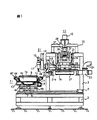
以下,本発明の一実施形態を図1,図2に基づいて説明する。
【0010】
図1,図2において、本発明による基板の組立方法を用いる基板組立装置は、液晶滴下部S1と基板貼合部S2から構成され、この両部分S1,S2は架台2上に隣接して配置される。
【0011】
架台2の上方には基板貼合部S2を支持するフレーム3がある。また、架台2の上面には、XYθステージT1が備えられている。Xステージ4aは、駆動モータ5により、図面上で左右のX軸方向に、即ち、液晶滴下部S1と基板貼合部S2間を往来できるようになっている。Yステージ4bはXステージ4a上にあり、駆動モータ6によりXステージ4aと直交するY軸方向に往来できるようになっている。θステージ4cはYステージ4b上にあり、回転ベアリング7を介して駆動モータ8によりYステージ4bに対して水平に回転可能になっていて、θステージ4c上に基板を搭載するテーブル9が固定されている。また、Yステージ4bにプレート13で下チャンバユニット10が固定されている。
【0012】
θステージ4cは、下チャンバユニット10に対し回転ベアリング11と真空シール12を介して回転自由に取付けられ、θステージ4cが回転しても、下チャンバユニット10は連られて回転しない。
【0013】
液晶滴下部S1は、テーブル9に保持された下基板1aに所望量の液晶剤を滴下するためのフレーム3から突出したブラケット14で支持されたディスペンサ17と、これを上下移動させるためのZ軸ステージ15と、それを駆動するモータ16で構成される。下基板1aをテーブル9上に保持搭載したXYθステージT1は、液晶剤を滴下するディスペンサ17のノズル18に対し、XおよびY方向に移動する。これにより、下基板1a上の任意の個所に所望量の液晶剤を滴下することができる。図1には示していないが、液晶剤を滴下するディスペンサ17とは別のシール剤を吐出するデイスペンサがフレーム3にあって、XYθステージT1の各モータ5,6で下基板1aをXY軸方向に移動させつつシール剤を吐出させると、下基板1a上にクローズ(閉鎖)したパターンでシール剤を描画できる。シール剤で形成したパターンの中に液晶剤を滴下する。
【0014】
液晶滴下後の下基板1aを搭載保持したXYθステージT1は、基板貼合部S2の下部に駆動モータ5によって移動する。
【0015】
基板貼合部S2では、上チャンバユニット21とその内部の加圧板27がそれぞれ独立して上下動できる構造になっている。即ち、上チャンバユニット21はリニアブッシュと真空シールを内蔵したハウジング30を有しており、フレーム3に固定されたシリンダ22のシャフトにより上下のZ軸方向に移動する。
【0016】
図2に、XYθステージT1が基板貼合部S2に移動していて上チャンバ21が下降した状態を示す。上チャンバユニット21が下降すると下チャンバユニット10の周りに配置してあるOリング44に上チャンバユニット21のフランジが接触し合体して、真空チャンバとして機能する状態になる。
【0017】
ここで、下チャンバユニット10のフランジ部に全周に渡って適宜な間隔で設置されたボールベアリング87は、真空チャンバを減圧することによって上下チャンバユニット10,21間に掛かる大気圧を負担してOリング44がつぶれる量を調整するもの(耐圧手段)で、ボルトナットの締め具合などで上下方向の任意の位置に設定可能となっている。
【0018】
Oリング44のつぶれ量は、真空チャンバ内を真空に保つことができ、かつ、最大の弾性が得られるものとする。このような手段がない場合、上チャンバユニット21は上チャンバユニット21の垂直投影面積に対応する大きな真空力(約1kgf/cm2)でOリング44をほとんどつぶしてしまうので、弾性変形が不可能になり、上下のチャンバユニット10.21がかじり合ってXYθステージT1の微動ができなくなる。本実施形態では、真空により発生する大きな力は、ボールベアリング87を介して下チャンバユニット10で受けており、Oリング44の弾性変形が可能で、また、下チャンバユニット10に設置されたボールベアリング87のボールはあらゆる方向に回転自在なので、後述するように基板貼合せ時にXYθステージT1をOリング44の弾性範囲内で容易に微動させ、基板同士の精密位置決めをすることができる。尚、XYθステージT1の微動量は、画像認識カメラ46により以下のようにして設定する。即ち、画像認識カメラ46は、ブラケット51を介してシャフト29に固定されており、加圧板27とともに上下動作する。図中、47は上チャンバユニット21の開孔48に真空漏れを起こさないように固定されたガラス製の覗き窓で、加圧板27にも開孔49があって、透視できるようになっている。また、画像認識カメラ46の作動距離(焦点距離)L1は、上基板1b上の基板合せマーク50bに合わせておく。この状態で上基板1bが加圧板27とともに下降し、焦点深度L2の範囲に下基板1aの基板合せマーク50aが入ると、上下両基板1a,1bのそれぞれの合せマーク50a,50bを同時にカメラ46で認識できる。この画像認識カメラ46は、例えば、上チャンバユニット21の対角位置に2台設置し、上下各基板1a,1bの2ヶ所の合せマークについて画像処理をして、そのずれ量をXYθステージT1の微動量として換算し、XYθステージT1の微動させ、上下両基板1a,1bの位置合せをすることができるようになっている。
【0019】
図1に戻って、23は真空バルブ、24は配管ホースで、図示していない真空源に接続され、これらは上下のチャンバユニット10,21を合体して形成される真空チャンバを減圧し、真空にする時に使用される。また、25はガスパージバルブ、26はガスチューブで、N2やクリーンドライエア等の圧力源に接続され、これらは真空チャンバ内を大気圧に戻す時に使用される。
【0020】
上基板1bは加圧板27の下面に密着保持されるが、大気下において上基板1bは吸引吸着で保持されるようになっている。即ち、41は吸引吸着用継手、42は吸引チューブであり、図示していない真空源に接続され、加圧板27の下面には、それにつながる複数の吸引孔が設けられている。また、周りが真空の場合、上基板1bは加圧板27の下面に機械的あるいは静電気的な作用で密着保持される。
【0021】
加圧板27はシャフト29で支持されており、シャフト29はハウジング31、32に固定されている。ハウジング31はフレーム3に対してリニアガイド34で取付けられ、加圧板27は上下動可能な構造になっている。その上下駆動はフレーム3とつながるフレーム35上のブラケット38に固定されたモータ40により行う。駆動の伝達はボールねじ36とナットハウジング37で実行される。ナットハウジング37は荷重計33を介してハウジング32とつながり、その下部の加圧板27と一体で動作する。
【0022】
従って、モータ40によってシャフト29が降下し、上基板1bを保持した加圧板27が降下し上基板1bがテーブル9上の下基板1aと密着して、加圧力を与えることのできる構造となっている。この場合、荷重計33は加圧力センサとして働き、逐次、フィードバックされた信号を基にモータ40を制御することで、上下基板1a,1bに所望の加圧力を与えることが可能となっている。尚、下基板1aも大気下では吸引吸着、真空下では機械的あるいは静電気的な手法などでテーブル9に密着保持される。
【0023】
次に、本発明による基板の組立方法の一実施形態として、本基板組立装置で基板を貼り合わせる工程について説明する。
【0024】
先ず、テーブル9に上基板1bを搭載し、駆動モータ5でXYθステージT1を基板貼合部S2に移動させる。そこでモータ40によりシャフト29を介して加圧板27を降下させ、テーブル9上の上基板1bを吸引吸着させてから、モータ40で上昇させて、上基板1bを待機状態とする。
【0025】
XYθステージT1は液晶滴下部S1に戻って、テーブル9上に下基板1aが搭載され、所望位置に固定保持される。
【0026】
図1には示していないシール剤のデイスペンサで、XYθステージT1の各モータ5,6で下基板1aをXY軸方向に移動させつつシール剤を吐出させ、下基板1a上にクローズ(閉鎖)したパターンでシール剤を描画する。その後、デイスペンサ17から液晶剤を下基板1a上に滴下する。この場合、シール剤がダムとなって、滴下した液晶剤は流失することはない。
【0027】
次に、XYθステージT1を基板貼合部S2に移動させ、シリンダ22で上チャンバユニット21を降下させ、そのフランジ部21aを図2に示すようにOリング44に当接させて下チャンバユニット10と合体させて真空チャンバを形成させる。そして、真空バルブ23を開放して真空チャンバ内を減圧していく。
【0028】
この間、基板1a,1b同士の位置合わせは、上チャンバユニット21に設けた覗き窓47から画像認識カメラ46で上下各基板1a,1bに設けられている位置合わせマークを読み取って画像処理により位置を計測し、XYθステージT1の各ステージ4a乃至4cを微動させて、高精度な位置合わせを行なう。この微動において、Oリング44が極端に変形しないで真空が維持されるように、ボールベアリング87が上下チャンバユニット10,21間に作用する大気圧を負担して上下チャンバユニット10,21の間隔を維持しているとともに、ボールベアリング87のボールの回転により、上下チャンバユニット10,21間の摩擦抵抗を軽減し、XYθステージT1における各ステージ4a乃至4cの下チャンバユニット10ごとのスムーズな微動を可能にしている。
【0029】
基板同士の位置合せ後にモータ40で加圧板27を降下させ、荷重計33で加圧力を計測しつつモータ40を制御して上下両基板1a,1bを所望間隔に貼り合わせる。加圧板27を降下させる際、ハウジング30にはリニアブッシュが内蔵されているので、仮に上下チャンバユニット10,21間に作用する大気圧で上チャンバユニット21が変形を起こしたとしても、シャフト29には影響を与えることはなく、位置合せ通りに基板1a,1bを貼り合すことができる。
【0030】
貼り合わせが終了すると、真空バルブ23を締めてガスパージバルブ25を開き、真空チャンバ内にN2やクリーンドライエアを供給し、大気圧に戻してからガスパージバルブ25を閉じて、シリンダ22で上チャンバユニット21を上昇させ、XYθステージT1を液晶滴下部S1に戻して、貼り合せで製作した表示パネルをテーブル9から外し、次の貼り合わせに備える。
【0031】
以上のように、減圧時に空気を放出する基板位置合せステージは真空チャンバの外にあり、しかも真空チャンバ容積は小さくなることによって、真空チャンバの減圧真空化は急速に進み、位置合せ精度も高く維持できて、組立の生産性は向上する。
【0032】
この実施形態ではXYθステージT1を基板の搬送手段としても利用しているので、装置は単純化し小型軽量化が図られている。
本発明は、以上説明した実施形態に限らず、以下の様に実施しても良い。
【0033】
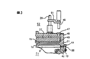
(1)ボールベアリング87の代わりに、真空チャンバに掛かる大気圧を耐えうるものであれば何でもよい。例えば図3に示すように、小径のバー88を適宜な間隔で下チャンバユニット10のフランジ部に立設してOリング44のつぶれ量を調整し、XYθステージT1の水平方向の微動は、小径のバー88の曲げ弾性の範囲で行わせるようにしてもよい。あるいは、下チャンバユニット10のフランジ部にOリング44を取り囲むように設けられ上チャンバユニットのフランジ部の全周に衝合して弾性変形する蛇腹などでもよい。
【0034】
(2)XYθステージT1は基板貼合部S2においてのみ微動でき、基板へのシール剤描画や液晶剤滴下は上流における設備機器で行って、基板の組立のみを行なうようにすることもできる。この場合、基板の搬入搬出はロボットハンドなどで実行する。
【0035】
(3)シール剤が液晶剤の性能を阻害するようなものであり、シール剤パターンの内側にシール剤と液晶剤を遮断する物質のパターンを設ける表示パネルに対しては、フレーム3にそのような遮断物質のディスペンサを設けて、XYθステージT1を利用して描画をしてもよい。
【0036】
(4)液晶表示パネルの製作だけでなく、位置合せをして真空中で貼り合せを行うものであれば、対象物は限定されない。
【0037】
(5)上下真空チャンバユニット10,21を合体させ、基板1a,1bの位置合せをしてから、真空チャンバの減圧真空化を行い、その後基板1a,1bの貼り合せをしても良い。この場合には真空チャンバの減圧真空化の前に位置合せが済んでいるために、耐圧手段は上下真空チャンバユニット10,21相対移動を許容する機能は不要で、耐圧機能を達成する単純な構成のもので済む利点がある。
【0038】
【発明の効果】
以上説明したように、本発明によれば、各基板に設けられた合わせマーク同士を高精度に一致させて速やかに貼り合せることができる。
【図面の簡単な説明】
【図1】 本発明による基板の組立方法の一実施形態を用いた基板組立装置を示す概略縦断面図である。
【図2】図1に示した基板組立装置における要部を示す図である。
【図3】図2に示した基板組立装置における要部の他の実施形態を示す図である。
【符号の説明】
1a 下基板
1b 上基板
9 テーブル
10 下チャンバユニット
21 上チャンバユニット
22 シリンダ
23 真空バルブ
40 モータ
44 Oリング
87 ボールベアリング
S1 液晶滴下部
S2 基板貼合部
T1 XYθステージ[0001]
BACKGROUND OF THE INVENTION
The present invention relates to a method of assembling a substrate, they are opposed to each other and held in particular be bonded boards, respectively, about the be bonded assembly method of the substrate by narrowing the gap with the positioning.
[0002]
[Prior art]
For the manufacture of liquid crystal display panels, two glass substrates with transparent electrodes and thin film transistor arrays are bonded together with an adhesive (hereinafter also referred to as a sealing agent) with an extremely close distance of about several μm (hereinafter, after bonding) The substrate is called a cell), and there is a step of sealing the liquid crystal in the space formed thereby.
[0003]
For sealing the liquid crystal, the liquid crystal is dropped on one substrate drawn in a pattern in which a sealing agent is closed so as not to provide an injection port, and the other substrate is placed on one substrate and placed in a vacuum. The method proposed in Japanese Patent Application Laid-Open No. Sho 62-165622, in which the upper and lower substrates are brought close together, and the substrate is bonded in a vacuum by patterning a sealing agent so as to provide an injection port on one of the substrates. Thereafter, there is a method proposed in Japanese Patent Laid-Open No. 10-26763 in which liquid crystal is injected from a sealing agent injection port.
[0004]
[Problems to be solved by the invention]
In both the above prior arts, the substrates are bonded together in a vacuum regardless of the sealant pattern. In that case, it is necessary to match at least two alignment marks provided on each substrate with an accuracy of several μm or less. In order to achieve this accuracy, in general, a horizontal fine movement mechanism such as an XY stage must be installed inside the vacuum chamber in order to operate one of the upper and lower substrates to match the alignment mark of the other substrate. Don't be.
[0005]
However, the horizontal fine movement mechanism such as the XY stage has a complicated structure, and there are many bolts, screw holes, other holes, grooves, gaps, etc., and it takes a very long time to depressurize the vacuum chamber and reach a predetermined degree of vacuum. And productivity is significantly reduced.
[0006]
SUMMARY OF THE INVENTION Therefore, an object of the present invention is to provide a method for assembling a substrate capable of quickly bonding the alignment marks provided on each substrate with high accuracy.
[0007]
[Means for Solving the Problems]
A feature of the method of the present invention that achieves the above-described object is that the substrates to be bonded are held and opposed to each other, positioning is performed and the interval is reduced, and an adhesive provided on one of the substrates is used in a vacuum chamber. In the case of bonding substrates, a vacuum chamber is formed from an upper chamber and a lower chamber, a pressure plate is disposed in the upper chamber, and the lower chamber is fixed on a stage that can move in a horizontal plane. The vacuum chamber is formed by providing a table on the stage, an O-ring around the lower chamber, and a flange portion of the lower chamber formed by the upper chamber contacting the O-ring the inner and adjusting the amount collapse of the O-ring when the pressure was reduced to allow elastic deformation of the O-ring, and a stage within the elastic range of the O-ring To permit fine movement in a horizontal plane under the chamber monitor, upper chamber when the pressure of the vacuum chamber, the breakdown voltage means for maintaining the spacing between the upper and lower chambers to bear the atmospheric pressure applied between the lower chamber A step of holding the upper substrate and the lower substrate on a pressure plate disposed in the upper chamber and a table disposed in the lower chamber, and the upper chamber having a flange portion of the upper chamber in the lower chamber. The vacuum chamber is formed by lowering and uniting with the lower chamber until it comes into contact with the ring, the step of reducing the pressure inside the vacuum chamber, and the pressure-reducing means of the lower chamber reduces the distance between the upper chamber and the lower chamber by the pressure reduction. while maintaining, by moving the stage in a horizontal plane, a step of aligning the upper substrate and the lower substrate, the upper substrate and the lower substrate by lowering the pressing plate It lies in including the step of bonding.
[0009]
DETAILED DESCRIPTION OF THE INVENTION
Hereinafter, an embodiment of the present invention will be described with reference to FIGS.
[0010]
1 and 2, the substrate assembly apparatus using the substrate assembly method according to the present invention is composed of a liquid crystal dropping part S1 and a substrate bonding part S2, and these parts S1 and S2 are arranged adjacent to each other on the
[0011]
Above the
[0012]
The
[0013]
The liquid crystal dropping unit S1 includes a
[0014]
The XYθ stage T1 on which the lower substrate 1a after liquid crystal dropping is mounted and held is moved by the drive motor 5 to the lower part of the substrate bonding portion S2.
[0015]
In the substrate bonding part S2, the
[0016]
FIG. 2 shows a state in which the XYθ stage T1 has moved to the substrate bonding unit S2 and the
[0017]
Here, the
[0018]
It is assumed that the collapse amount of the O-
[0019]
Returning to FIG. 1, 23 is a vacuum valve, 24 is a piping hose, and is connected to a vacuum source (not shown), which depressurizes a vacuum chamber formed by combining the upper and
[0020]
The upper substrate 1b is held in close contact with the lower surface of the
[0021]
The
[0022]
Therefore, the
[0023]
Next, as an embodiment of the substrate assembling method according to the present invention, a step of bonding substrates with the substrate assembling apparatus will be described.
[0024]
First, the upper substrate 1b is mounted on the table 9, and the XYθ stage T1 is moved to the substrate bonding portion S2 by the drive motor 5. Therefore, the
[0025]
The XYθ stage T1 returns to the liquid crystal dropping unit S1, and the lower substrate 1a is mounted on the table 9 and fixedly held at a desired position.
[0026]
A dispenser of sealant not shown in FIG. 1 is used to discharge the sealant while moving the lower substrate 1a in the XY axis directions by the motors 5 and 6 of the XYθ stage T1, and close (close) the lower substrate 1a on the lower substrate 1a. Draw sealant with a pattern. Thereafter, a liquid crystal agent is dropped from the
[0027]
Next, the XYθ stage T1 is moved to the substrate bonding portion S2, the
[0028]
During this time, the substrates 1a and 1b are aligned with each other by reading the alignment marks provided on the upper and lower substrates 1a and 1b from the
[0029]
After the alignment between the substrates, the
[0030]
When the bonding is completed, the
[0031]
As described above, the substrate alignment stage that releases air at the time of depressurization is outside the vacuum chamber, and the vacuum chamber volume is reduced, so that the vacuum chamber is rapidly reduced in vacuum and alignment accuracy is maintained at a high level. This improves assembly productivity.
[0032]
In this embodiment, since the XYθ stage T1 is also used as a substrate transfer means, the apparatus is simplified and reduced in size and weight.
The present invention is not limited to the embodiment described above, and may be implemented as follows.
[0033]
(1) Instead of the
[0034]
(2) The XYθ stage T1 can be finely moved only at the substrate bonding portion S2, and the sealing agent drawing and the liquid crystal agent dripping onto the substrate can be performed by the upstream equipment and only the assembly of the substrate can be performed. In this case, the substrate is carried in and out with a robot hand or the like.
[0035]
(3) For a display panel in which the sealant impedes the performance of the liquid crystal agent, and a pattern of a substance that blocks the sealant and the liquid crystal agent is provided on the inner side of the sealant pattern, such as the frame 3 An appropriate blocking substance dispenser may be provided to draw using the XYθ stage T1.
[0036]
(4) The object is not limited as long as the liquid crystal display panel is not only manufactured but also aligned and bonded in a vacuum.
[0037]
(5) The upper and lower
[0038]
【The invention's effect】
As described above, according to the present invention, alignment marks provided on each substrate can be quickly bonded together with high accuracy.
[Brief description of the drawings]
FIG. 1 is a schematic longitudinal sectional view showing a substrate assembling apparatus using an embodiment of a substrate assembling method according to the present invention.
FIG. 2 is a view showing a main part of the board assembly apparatus shown in FIG. 1;
FIG. 3 is a diagram showing another embodiment of the main part of the board assembly apparatus shown in FIG. 2;
[Explanation of symbols]
1a Lower substrate
Claims (5)
該真空チャンバは上チャンバ及び下チャンバから形成され、該上チャンバ内には、加圧板が配置され、さらに、該下チャンバは、水平面内での移動が可能なステージ上に固定して配置されて、該ステージ上にテーブルが設けられ、
かつ該下チャンバの周りにOリングが配置されるとともに、該下チャンバのフランジ部に、該上チャンバが該Oリングに当接することによって形成された該真空チャンバ内を減圧したときの該Oリングのつぶれ量を調整して、該Oリングを弾性変形可能にし、該Oリングの弾性範囲内で該ステージとともに該下チャンバの水平面内での微動を可能に、該真空チャンバ内を減圧したときの該上チャンバ,該下チャンバ間に掛かる大気圧を負担して該上チャンバと該下チャンバとの間隔を維持する耐圧手段が設けられており、
該上チャンバ内に配置された該加圧板及び該下チャンバ内に配置された該テーブルに上基板及び下基板を保持する工程と、
該上チャンバを、該上チャンバのフランジ部が該下チャンバでの該Oリングに接触するまで、降下させて該下チャンバと合体させ、真空チャンバを形成する工程と、
該真空チャンバ内を減圧する工程と、
該減圧によって該下チャンバの該耐圧手段が該上チャンバと該下チャンバとの該間隔を維持した状態で、該ステージを水平面内で移動させることにより、該上基板及び該下基板の位置合わせを行なう工程と、
該加圧板を降下させて該上基板と該下基板とを貼り合わせる工程と
を含むことを特徴とする基板の組立方法。In the method of assembling the substrates, the substrates to be bonded are held and opposed to each other, positioning and narrowing the interval, and the substrates are bonded to each other in a vacuum chamber by an adhesive provided on one of the substrates,
The vacuum chamber is formed of an upper chamber and a lower chamber, a pressure plate is disposed in the upper chamber, and the lower chamber is fixedly disposed on a stage that can move in a horizontal plane. A table is provided on the stage;
An O-ring is disposed around the lower chamber, and the O-ring is decompressed in the vacuum chamber formed by the upper chamber contacting the O-ring at the flange portion of the lower chamber. When the inside of the vacuum chamber is depressurized so that the O-ring can be elastically deformed by adjusting the amount of collapse of the vacuum chamber, and fine movement in the horizontal plane of the lower chamber can be performed together with the stage within the elastic range of the O-ring . Pressure-resistant means is provided for maintaining an interval between the upper chamber and the lower chamber by bearing an atmospheric pressure applied between the upper chamber and the lower chamber ;
A step of holding the upper substrate and the lower substrate arranged the table on the upper arranged the pressure plate and the lower chamber into the chamber,
Lowering and combining the upper chamber with the lower chamber until the flange portion of the upper chamber contacts the O-ring in the lower chamber to form a vacuum chamber;
Reducing the pressure in the vacuum chamber;
By moving the stage in a horizontal plane with the pressure-reducing means of the lower chamber maintaining the distance between the upper chamber and the lower chamber by the pressure reduction, the upper substrate and the lower substrate are aligned. Performing steps;
And a step of lowering the pressure plate to bond the upper substrate and the lower substrate together.
前記テーブルに保持されている前記下基板には、所望量の液晶剤が滴下されていることを特徴とする基板の組立方法。The method of assembling a substrate according to claim 1.
A method of assembling a substrate, wherein a desired amount of liquid crystal agent is dropped on the lower substrate held on the table.
前記上チャンバと前記加圧板とは夫々独立して上下動可能であることを特徴とする基板の組立方法。The method for assembling a substrate according to claim 2,
The substrate assembling method, wherein the upper chamber and the pressure plate can be moved up and down independently.
前記上基板及び前記下基板の位置合わせを行なう工程では、前記上基板と前記下基板とに設けられた位置合わせマークを画像認識カメラで撮像して、該位置合わせマークのずれ量を求め、該ずれ量を前記テーブルの移動量に換算して前記テーブルを移動させることを特徴とする基板の組立方法。The substrate assembly method according to claim 2 or 3,
In the step of aligning the upper substrate and the lower substrate, an alignment mark provided on the upper substrate and the lower substrate is imaged by an image recognition camera, and a displacement amount of the alignment mark is obtained, A substrate assembling method, wherein the table is moved by converting a shift amount into a movement amount of the table.
前記加圧板を降下させて前記上基板と前記下基板とを貼り合わせる工程では、荷重計で加圧力を計測して前記上基板と前記下基板とを所望間隔で貼り合わせることを特徴とする基板の組立方法。The substrate assembly method according to claim 2 or 3,
In the step of bonding the upper substrate and the lower substrate by lowering the pressure plate , the pressing force is measured by a load meter, and the upper substrate and the lower substrate are bonded at a desired interval. Assembly method.
Priority Applications (1)
| Application Number | Priority Date | Filing Date | Title |
|---|---|---|---|
| JP2003143670A JP4389474B2 (en) | 2003-05-21 | 2003-05-21 | Board assembly method |
Applications Claiming Priority (1)
| Application Number | Priority Date | Filing Date | Title |
|---|---|---|---|
| JP2003143670A JP4389474B2 (en) | 2003-05-21 | 2003-05-21 | Board assembly method |
Related Parent Applications (1)
| Application Number | Title | Priority Date | Filing Date |
|---|---|---|---|
| JP17290399A Division JP3535044B2 (en) | 1999-03-30 | 1999-06-18 | Substrate assembling apparatus and method, and liquid crystal panel manufacturing method |
Publications (3)
| Publication Number | Publication Date |
|---|---|
| JP2003302614A JP2003302614A (en) | 2003-10-24 |
| JP2003302614A5 JP2003302614A5 (en) | 2006-05-18 |
| JP4389474B2 true JP4389474B2 (en) | 2009-12-24 |
Family
ID=29398361
Family Applications (1)
| Application Number | Title | Priority Date | Filing Date |
|---|---|---|---|
| JP2003143670A Expired - Fee Related JP4389474B2 (en) | 2003-05-21 | 2003-05-21 | Board assembly method |
Country Status (1)
| Country | Link |
|---|---|
| JP (1) | JP4389474B2 (en) |
-
2003
- 2003-05-21 JP JP2003143670A patent/JP4389474B2/en not_active Expired - Fee Related
Also Published As
| Publication number | Publication date |
|---|---|
| JP2003302614A (en) | 2003-10-24 |
Similar Documents
| Publication | Publication Date | Title |
|---|---|---|
| JP3535044B2 (en) | Substrate assembling apparatus and method, and liquid crystal panel manufacturing method | |
| JP3641709B2 (en) | Substrate assembly method and apparatus | |
| JP3707990B2 (en) | Board assembly equipment | |
| JP3486862B2 (en) | Substrate assembly method and apparatus | |
| JP3411023B2 (en) | Board assembly equipment | |
| KR100362721B1 (en) | Substrate bonding apparatus | |
| CN100381881C (en) | Device and method for fabricating liquid-crystal display device | |
| KR20060121751A (en) | Substrate assembling apparatus and method | |
| JP3422291B2 (en) | How to assemble a liquid crystal substrate | |
| JP3906753B2 (en) | Board assembly equipment | |
| JP3577545B2 (en) | Substrate bonding equipment | |
| JP2002318378A (en) | Method for assembling liquid crystal display device and its device | |
| KR100360833B1 (en) | Substrate assembling apparatus | |
| JP3557472B2 (en) | Liquid crystal substrate assembling method, assembling apparatus and liquid crystal supply apparatus | |
| KR100720423B1 (en) | substrates bonding device for manufacturing of liquid crystal display and method thereof | |
| JP4389474B2 (en) | Board assembly method | |
| TWI222671B (en) | Apparatus for fabricating bonded substrate | |
| JP2002323687A (en) | Method and device for assembling liquid crystal substrate | |
| JP3535150B2 (en) | Substrate assembly method and apparatus | |
| JP3458145B2 (en) | Substrate bonding method and apparatus | |
| JP4224959B2 (en) | Liquid crystal substrate assembly equipment | |
| JP2002090703A (en) | Apparatus and method for assembling substrate for liquid crystal | |
| JP3773866B2 (en) | Substrate assembly method and apparatus | |
| KR100728854B1 (en) | System for producing pasted substrate | |
| JP4470923B2 (en) | Board assembly equipment |
Legal Events
| Date | Code | Title | Description |
|---|---|---|---|
| A521 | Written amendment |
Free format text: JAPANESE INTERMEDIATE CODE: A523 Effective date: 20060328 |
|
| A621 | Written request for application examination |
Free format text: JAPANESE INTERMEDIATE CODE: A621 Effective date: 20060328 |
|
| A711 | Notification of change in applicant |
Free format text: JAPANESE INTERMEDIATE CODE: A712 Effective date: 20060920 |
|
| RD02 | Notification of acceptance of power of attorney |
Free format text: JAPANESE INTERMEDIATE CODE: A7422 Effective date: 20061013 |
|
| A977 | Report on retrieval |
Free format text: JAPANESE INTERMEDIATE CODE: A971007 Effective date: 20080516 |
|
| A131 | Notification of reasons for refusal |
Free format text: JAPANESE INTERMEDIATE CODE: A131 Effective date: 20080527 |
|
| A521 | Written amendment |
Free format text: JAPANESE INTERMEDIATE CODE: A523 Effective date: 20080717 |
|
| A521 | Written amendment |
Free format text: JAPANESE INTERMEDIATE CODE: A523 Effective date: 20080801 |
|
| A131 | Notification of reasons for refusal |
Free format text: JAPANESE INTERMEDIATE CODE: A131 Effective date: 20090630 |
|
| A521 | Written amendment |
Free format text: JAPANESE INTERMEDIATE CODE: A523 Effective date: 20090825 |
|
| TRDD | Decision of grant or rejection written | ||
| A01 | Written decision to grant a patent or to grant a registration (utility model) |
Free format text: JAPANESE INTERMEDIATE CODE: A01 Effective date: 20090915 |
|
| A01 | Written decision to grant a patent or to grant a registration (utility model) |
Free format text: JAPANESE INTERMEDIATE CODE: A01 |
|
| A61 | First payment of annual fees (during grant procedure) |
Free format text: JAPANESE INTERMEDIATE CODE: A61 Effective date: 20090928 |
|
| FPAY | Renewal fee payment (event date is renewal date of database) |
Free format text: PAYMENT UNTIL: 20121016 Year of fee payment: 3 |
|
| R150 | Certificate of patent or registration of utility model |
Free format text: JAPANESE INTERMEDIATE CODE: R150 |
|
| FPAY | Renewal fee payment (event date is renewal date of database) |
Free format text: PAYMENT UNTIL: 20131016 Year of fee payment: 4 |
|
| S111 | Request for change of ownership or part of ownership |
Free format text: JAPANESE INTERMEDIATE CODE: R313111 |
|
| R350 | Written notification of registration of transfer |
Free format text: JAPANESE INTERMEDIATE CODE: R350 |
|
| LAPS | Cancellation because of no payment of annual fees |