JP4388005B2 - Context switching device - Google Patents
Context switching device Download PDFInfo
- Publication number
- JP4388005B2 JP4388005B2 JP2005294190A JP2005294190A JP4388005B2 JP 4388005 B2 JP4388005 B2 JP 4388005B2 JP 2005294190 A JP2005294190 A JP 2005294190A JP 2005294190 A JP2005294190 A JP 2005294190A JP 4388005 B2 JP4388005 B2 JP 4388005B2
- Authority
- JP
- Japan
- Prior art keywords
- transfer
- context
- processor
- priority
- processors
- Prior art date
- Legal status (The legal status is an assumption and is not a legal conclusion. Google has not performed a legal analysis and makes no representation as to the accuracy of the status listed.)
- Expired - Fee Related
Links
Images


Classifications
-
- G—PHYSICS
- G06—COMPUTING; CALCULATING OR COUNTING
- G06F—ELECTRIC DIGITAL DATA PROCESSING
- G06F9/00—Arrangements for program control, e.g. control units
- G06F9/06—Arrangements for program control, e.g. control units using stored programs, i.e. using an internal store of processing equipment to receive or retain programs
- G06F9/46—Multiprogramming arrangements
- G06F9/461—Saving or restoring of program or task context
- G06F9/462—Saving or restoring of program or task context with multiple register sets
Landscapes
- Engineering & Computer Science (AREA)
- Software Systems (AREA)
- Theoretical Computer Science (AREA)
- Physics & Mathematics (AREA)
- General Engineering & Computer Science (AREA)
- General Physics & Mathematics (AREA)
- Multi Processors (AREA)
- Memory System (AREA)
Description
本発明は、プロセッサに関するものであり、特にマルチプロセッサシステムにおいて効率的にプログラムを実行する技術に関する。 The present invention relates to a processor, and more particularly to a technique for efficiently executing a program in a multiprocessor system.
複数のプログラムを1つのプロセッサで並列実行する並列処理システムにおいて、プロセッサはプログラムの実行単位であるタスクを決められた要因によって切替えながら実行する。この制御により、1つのプロセッサで複数のプログラムを擬似的に並列実行させている。 In a parallel processing system in which a plurality of programs are executed in parallel by a single processor, the processor executes a task, which is a program execution unit, while switching according to a determined factor. By this control, a plurality of programs are executed in a pseudo parallel manner by one processor.
また、各タスクは各々がプロセッサを独占して使用するように実行されるため、各々のタスクが個別に仮想的なプロセッサに割り当てられて実行されていると考えることができる。 Further, since each task is executed so that each processor exclusively uses the processor, it can be considered that each task is individually assigned to a virtual processor and executed.
仮想的なプロセッサは、実際のプロセッサの全機能を持つ必要はなく、タスクを実行するために必要な情報、すなわちプログラムカウンタ、フラグレジスタ、スタック領域、汎用レジスタなどの制御情報やデータ情報のみを持てばよい。タスクを実行するために必要なこれらの情報を「コンテキスト」という。 A virtual processor does not need to have all the functions of an actual processor, but can only have information necessary for executing a task, that is, control information and data information such as a program counter, a flag register, a stack area, and general-purpose registers. That's fine. Such information necessary for executing the task is referred to as “context”.
実行中のタスクを別のタスクに切替えるときには、コンテキストを切替えなければならない。通常、コンテキストはメモリに格納されているため、コンテキストの切替えとは現在実行しているタスクのコンテキストをメモリに書き出し(ここでは「退避」と書く)、次に実行するタスクのコンテキストをメモリから読み出す(ここでは「復帰」と書く)動作を意味する。 When switching a running task to another task, the context must be switched. Usually, since the context is stored in the memory, context switching is to write the context of the currently executing task to the memory (in this case, “save”), and to read the context of the next task to be executed from the memory (Here, it is written as “return”).
従来、このコンテキストの切替えはOS(Operating System)が行う方法の他に、例えば特許文献1のようにハードウェアで行う方法があった。コンテキストの切替えを行うハードウェアのことをコンテキスト切替え装置という。
Conventionally, in addition to the method performed by an OS (Operating System), there is a method performed by hardware as disclosed in
図17は、従来のコンテキスト切替え装置の構成を示す機能ブロック図である。
図17において、従来のコンテキスト切替え装置1001は、プロセッサ1002と、コンテキストを格納するメモリ1003とを備える。なお、ここではコンテキストを切替える動作の説明を簡単にするため、本図では説明に必要な機能ブロックのみを記載している。
FIG. 17 is a functional block diagram showing a configuration of a conventional context switching device.
In FIG. 17, a conventional
プロセッサ1002は、プロセッサユニット1004と、コンテキストを格納するレジスタ群A1005,レジスタ群B1006と、コンテキスト選択部1007とから構成される。
The
プロセッサ1002は、次の手順でタスクの切替えを行う。ここでは、現在実行しているタスクをタスク1とし、次にタスク2に処理を切替える場合について説明する。現在実行中のタスク1のコンテキストがレジスタ群A1005に格納されているとする。
The
1. 次に実行するタスク2のコンテキストをメモリ1003からレジスタ群B1006に復帰させる。
1. The context of
2.実行するタスクがタスク1からタスク2に切り換わるときに、プロセッサユニット1004がレジスタ群B1006、およびコンテキスト切替え装置1001がレジスタ群A1005をアクセスするようにコンテキスト選択部1007が制御する。
2. When the task to be executed is switched from
3.タスク2の実行を開始したのち、レジスタ群A1005に格納されているタスク1のコンテキストをメモリ1003に退避する。
3. After execution of
図18は、このコンテキスト切替えの手順を図に示したものである。
まず、処理の前提を、図18(a)で説明する。
FIG. 18 shows the context switching procedure.
First, the premise of processing will be described with reference to FIG.
プログラム(1)とプログラム(2)という2つのプログラムをプロセッサ1002で実行するとする。各プログラムは、独立した2つの仮想的なプロセッサの各々に割り当てられているように動作するが、この仮想的なプロセッサのことを論理プロセッサ(以後LPと記す)と呼ぶ。そして、プロセッサ1002は2つのプログラム(1)および(2)を、タスクごとに切替えながら実行する。以後、例えばプログラム(1)を実行することを「プロセッサ1002でLP(1)を実行する」と記す。
Assume that the
図18(b)は、プロセッサ1002で実行するLP(1)及びLP(2)の実行時間とLP(2)のコンテキスト復帰要求との関係を表す図である。
FIG. 18B is a diagram illustrating the relationship between the execution times of LP (1) and LP (2) executed by the
プロセッサ1002は時刻T0でLP(1)の実行を開始し、時刻T3でLP(2)に処理を切替える。
The
時刻T3でLP(2)の実行を開始するために時刻T1でLP(2)のコンテキストの復帰を開始する。コンテキストの復帰を開始する要因を「コンテキストの復帰要求」と書く。コンテキストの復帰要求が発生するとコンテキスト切替え装置1001のデータ転送制御部1009はコンテキストの復帰処理を開始して、時刻T2に完了する。
In order to start execution of LP (2) at time T3, return of context of LP (2) is started at time T1. The factor for starting the context return is written as “context return request”. When a context return request is generated, the data
以後、「コンテキストの復帰要求」と「コンテキストの退避要求」を合わせて、「コンテキスト切替え要求」と書く。 Hereinafter, the “context return request” and the “context save request” are collectively referred to as “context switching request”.
コンテキスト切替え要求は、コンテキスト切替え装置1001の内部で生成する。生成の方法についてはいくつかの手法が考えられるが、ここでは各LPの実行開始時間を基準として、ある特定の時間が経過したときにコンテキスト切替え装置1001内で生成するという手法を用いる。各LPの実行時間は図17のカウンタ1500で計数する。
The context switching request is generated inside the
また、タスクを切替えるタイミングを決める方法についてもいくつかの手法が考えられるが、ここではカウンタ1500で計数したLPの実行時間が、ある特定の時間に達したときにタスクを切替える要因をコンテキスト切替え装置1001内で生成する手法を用いる。
Several methods are also conceivable for determining the task switching timing. Here, the context switching device is a factor for switching tasks when the LP execution time counted by the
この従来例によれば、確かに1つのプロセッサではコンテキストの切替えによるオーバーヘッドがなく、効率的にタスクの切替えを行うことができる。
ところで、近年、処理の高速化のため、共有メモリの数を少なくしつつプロセッサの複数化を図りたいといった要望がある。 By the way, in recent years, there is a demand to increase the number of processors while reducing the number of shared memories in order to increase the processing speed.
しかしながら、このように複数のタスクを擬似並行的に処理するプロセッサ1002を複数個並列に動作させ、かつ共有メモリにすべてのプロセッサで実行するタスクのコンテキストを格納する場合、複数個のプロセッサの共有メモリへのアクセス(すなわち、コンテキストの復帰や退避)が競合することがあり、タスクの実行完了から次のタスクの実行開始までに時間がかかってしまうという問題がある。
However, when a plurality of
図18(b)の記号で説明すると、共有メモリへのアクセスの競合の問題で、コンテキストの復帰が完了する時刻T2が、本来LP(1)からLP(2)へ処理を切替える時刻T3よりも遅れてしまう場合がある。LP(1)のコンテキストの復帰が完了するまでLP(2)の実行を開始できないので、結果としてタスク切替え時に不要な時間を消費してしまうことになる。 18 (b), the time T2 at which the context restoration is completed due to the contention of access to the shared memory is more than the time T3 at which the processing is originally switched from LP (1) to LP (2). There may be a delay. Since execution of LP (2) cannot be started until the return of the context of LP (1) is completed, unnecessary time is consumed when switching tasks.
そこで、上述の課題を解決し、複数のプロセッサにおけるコンテキストの復帰や退避によるアクセスの競合を軽減することが可能なコンテキスト切替え装置を提供することを目的とする。 Accordingly, an object of the present invention is to provide a context switching apparatus that can solve the above-described problems and reduce contention of access due to context restoration and saving in a plurality of processors.
上記目的を達成するために、コンテキスト切替え装置においては、複数のプログラムを切替えながら実行するN個のプロセッサと、M(M<N)個のアクセスポートを有し、前記N個のプロセッサから退避されたコンテキストデータを記憶する共有メモリとを含む並列システムに用いられ、各プロセッサと共有メモリとの間でコンテキストデータを並列に転送することによって各プロセッサのコンテキストを切替えるコンテキス切替え装置であって、コンテキストデータの転送を連続サイクルで行う第1転送モード、およびコンテキストデータ転送をサイクル毎に対象とするプロセッサを切替えながら行う第2転送モードの少なくとも一方によりコンテキストデータを転送する転送手段と、M個より多い数のプロセッサからのコンテキスト切替え要求が競合した場合に、第1転送モードの対象とすべきプロセッサと、第2転送モードの対象とすべきプロセッサとを決定し、決定に従って転送手段を制御する制御手段とを備えることを特徴とする。 In order to achieve the above object, the context switching device has N processors that execute while switching a plurality of programs and M (M <N) access ports, and is saved from the N processors. A context switching device that is used in a parallel system including a shared memory that stores context data, and that switches the context of each processor by transferring the context data between each processor and the shared memory in parallel. Transfer means for transferring context data in at least one of a first transfer mode in which transfer is performed in successive cycles and a second transfer mode in which context data transfer is performed while switching the target processor for each cycle, and a number greater than M Context from other processors Control means for determining a processor to be the target of the first transfer mode and a processor to be the target of the second transfer mode when the requests conflict, and controlling the transfer means according to the determination. And
これによって、共有メモリに対して複数のプロセッサがコンテキストデータ転送を行う場合においても、共有メモリへのアクセスの競合がタスクの切替え処理に与える影響を最小限に抑えられ、タスクの切替えの時間ロスを大幅に削減することが可能となる。したがって、上述の課題を解決し、複数のプロセッサにおけるコンテキストの復帰や退避によるアクセスの競合を軽減することが可能なコンテキスト切替え装置を提供することができる。 As a result, even when multiple processors transfer context data to the shared memory, the influence of contention on access to the shared memory on task switching processing can be minimized, and task switching time loss can be reduced. It becomes possible to reduce significantly. Therefore, it is possible to provide a context switching device that can solve the above-described problems and can reduce contention of access due to context restoration and saving in a plurality of processors.
なお、本発明は、このようなコンテキスト切替え装置として実現することができるだけでなく、このようなコンテキスト切替え装置を含む並列システムとして構成したり、コンテキスト切替え装置を一体化したLSIとして実現したり、コンテキスト切替え装置が備える特徴的な手段をステップとするコンテキスト切替え方法として実現したり、それらのステップをコンピュータに実行させるプログラムとして実現したりすることもできる。そして、そのようなプログラムは、CD−ROM等の記録媒体やインターネット等の伝送媒体を介して配信することができるのは言うまでもない。 The present invention can be realized not only as such a context switching device, but also as a parallel system including such a context switching device, as an LSI integrated with the context switching device, It can also be realized as a context switching method using characteristic means of the switching device as steps, or as a program for causing a computer to execute these steps. Needless to say, such a program can be distributed via a recording medium such as a CD-ROM or a transmission medium such as the Internet.
以上の説明から明らかなように、本発明によれば、共有メモリに対して複数のプロセッサがコンテキストデータ転送を行う場合においても、共有メモリへのアクセスの競合がタスクの切替え処理に与える影響を最小限に抑えられ、タスクの切替えの時間ロスを大幅に削減することが可能となる。 As is apparent from the above description, according to the present invention, even when a plurality of processors transfer context data to the shared memory, the influence of contention on access to the shared memory on the task switching process is minimized. As a result, the time loss of task switching can be greatly reduced.
よって、本発明により、オーバーヘッドが軽減され、並列システムが普及してきた今日における本願発明の実用的価値は極めて高い。 Therefore, the practical value of the present invention is very high today, where overhead is reduced and parallel systems have become widespread by the present invention.
以下、本発明の実施の形態について、図面を用いて詳細に説明する。 Hereinafter, embodiments of the present invention will be described in detail with reference to the drawings.
(実施の形態1)
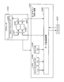
図1は本発明の実施の形態1に係るコンテキスト切替え装置を用いた、並列システムの全体構成を示す機能ブロック図である。
(Embodiment 1)
FIG. 1 is a functional block diagram showing the overall configuration of a parallel system using the context switching device according to
図1に示されるように、並列システム1は、複数の物理的プロセッサから構成されるプロセッサ20と、複数のコンテキストメモリから構成される共有メモリ30と、コンテキスト切替え装置10とを備える。プロセッサ20は、コンテキスト切替え装置10を介して、共有メモリ30に対してコンテキストデータの復帰あるいは退避を行う。
As shown in FIG. 1, the
コンテキスト切替え装置10は、転送モード格納部11と、優先度判定部12と、データ転送制御部13と、複数のカウンタ15とを備える。
The
転送モード格納部11は、レジスタで構成され、プロセッサ20が1つのプロセッサとして動作するシステムモードにおいて、コンテキスト転送モードに関する情報をこのプロセッサ20から書き込む。このコンテキスト転送モードに関する情報は、連続転送プロセッサ数111と、コンテキスト転送属性112と、選択情報113と、モード選択情報114とで構成される。
The transfer
優先度判定部12は、転送モード格納部11に格納されているコンテキスト転送モードに関する情報と、上記システムモードにおいてプロセッサ20から転送されてくる優先度情報等とに基づいてデータ転送制御部13に必要な情報を生成するものであり、優先度格納部121と、実行時間比較部122と、割り込み情報生成部123と、転送待ち時間計数部124と、選択部125と、データ転送情報生成部126とを備える。
The
データ転送制御部13は、優先度判定部12が生成した情報に基づいて、コンテキストを転送する順番を動的に切替えることにより、複数のプロセッサにおけるコンテキストの復帰や退避によるアクセスの競合を軽減するものであり、転送中断制御部131と、最大アクセス数格納部132と、制御部133と、データ経路切替え部134とを備える。
The data
カウンタ15は、各LPに割り当てられた実行サイクル数の残り時間を計数する。
なお、データ転送制御部13のデータ経路切替え部134は、請求項における転送手段を構成し、転送モード格納部11、優先度判定部12およびデータ転送制御部13の転送中断制御部131、最大アクセス数格納部132、制御部133によって請求項における制御手段が構成される。
The counter 15 counts the remaining time of the number of execution cycles assigned to each LP.
The data
次いで、転送モード格納部11、優先度判定部12およびデータ転送制御部13の構成をさらに詳細に説明する。
Next, the configuration of the transfer
まず転送モード格納部11について、図2を用いて説明する。
コンテキスト転送モードに関する情報は、上記したように、連続転送プロセッサ数111と、コンテキスト転送属性112と、選択情報113と、モード選択情報114との4つの情報で構成される。
First, the transfer
As described above, the information related to the context transfer mode includes four pieces of information including the continuous
連続転送プロセッサ数111は、複数のLPのコンテキスト切替え要求が競合したときに、コンテキストデータを連続転送するプロセッサの個数の情報である。共有メモリ30には最大M個のプロセッサからのデータ転送を実行することができるので、連続転送プロセッサ数111の有効な最小の設定値は「0」、また有効な最大の設定値は「M」である。
The continuous
コンテキスト転送属性112は、各LPを実行する際のコンテキストデータの転送を、連続転送するか否かを指定する情報である。なお、ここではプロセッサ20で実行するLPの最大数を「S」として説明する。
The
選択情報113は、連続転送プロセッサ数111の情報とコンテキスト転送属性112のいずれの情報を有効にするかを選択する情報である。選択情報113によって選択した連続転送プロセッサ数111の情報またはコンテキスト転送属性112の情報を、転送モード情報110として出力する。
The
モード選択情報114は、優先度格納部121が生成する情報と、実行時間比較部122が生成する情報とのいずれかを、優先度判定部12の選択部125に選択させる情報である。
The
次に、優先度判定部12について図3を用いて説明する。
優先度判定部12は、優先度格納部121と、実行時間比較部122と、割り込み情報生成部123と、転送待ち時間計数部124と、選択部125と、データ転送情報生成部126とを備える。
Next, the
The
優先度格納部121は、各LPのコンテキストデータ転送の優先度情報を格納する。この優先度情報は最大S個の情報で構成される。ここでは便宜上、優先度情報「1」が最も優先度が高いことを表すものとし、順に優先度情報「1」、「2」、…、「S」と割り振る。たとえば、S=3のとき、LP(1),LP(2),LP(3)の3つのLPが定義されているが、LP(2),LP(1),LP(3)の順にコンテキストデータの転送優先度の高い場合、LP(1),LP(2),LP(3)の各LPの優先度情報はそれぞれ「2」、「1」、「3」である。なお、優先度格納部121には、システムモードにおいてプロセッサ20から優先度情報が格納される。
The
実行時間比較部122は、各LPに割り当てられた実行サイクル数の残り時間を計数するカウンタ15の計数値を入力し、タスク切替えまでの残り時間が短いものから順に上述した優先度情報を付与した情報を生成する。
The execution
割り込み情報生成部123は、外部から割り込み信号400が入力されると、割り込み信号400に対応づけられたLPを特定し、さらに特定したLP番号の優先度を特定する。そののち、割り込み情報生成部123は選択部125に対して、割り込み信号400に対応したLPのLP番号情報、特定した優先度情報、及び切替え要求信号を出力する。
When an interrupt signal 400 is input from the outside, the interrupt
転送待ち時間計数部124は、制御部133からの情報に基づき、コンテキストデータ転送待ちの状態になったあとに転送をスキップされた回数(先にコンテキストデータを転送したLPの個数)を計数し、計数した値が所定の回数に達したときには、転送待ちのLPに最も高い優先度を付与して、切替え要求とともに選択部125に出力する。
Based on the information from the
選択部125は、転送モード格納部11が出力するモード選択情報114を入力し、実行時間比較部122が生成する各LPの優先度情報と、優先度格納部121が生成する各LPの優先度情報のいずれか一方の情報を選択して出力する。ただし、選択部125は、割り込み情報生成部123や転送待ち時間計数部124が生成する切替え要求信号が入力されているときは、後述するようにそれぞれが生成するLP番号情報を受け付ける。
The
データ転送情報生成部126は、転送モード情報110の情報と、選択部125の情報とを入力し、連続転送するプロセッサ番号情報127、連続転送しないプロセッサ番号情報128、及び転送中断情報129を出力する。
The data transfer
例えば、M=3のシステムで、転送モード情報110が「連続転送プロセッサ数が1である」という情報であり、さらに選択部125から入力する情報が「プロセッサP(1)でLP(1)、プロセッサP(2)でLP(2)、プロセッサP(3)でLP(3)が実行されており、LP(1),LP(2),LP(3)の優先度がそれぞれ「2」、「1」、「3」である」場合、連続転送するプロセッサ番号情報127としてLP(2)を実行しているプロセッサP(2)のプロセッサ番号すなわち「2」、連続転送しないプロセッサ番号情報128としてLP(1)とLP(3)をそれぞれ実行しているプロセッサP(1)およびP(3)のプロセッサ番号すなわち「1」と「3」を出力する。
For example, in a system with M = 3, the transfer mode information 110 is information that “the number of continuous transfer processors is one”, and the information input from the
さらにデータ転送情報生成部126は、後述するように、あるプロセッサのコンテキストデータを転送中に、より高い優先度のLPを実行しているプロセッサのコンテキスト切替え要求が発生したときには、転送中断情報129を出力する。
Further, as will be described later, when a context switching request for a processor executing a higher priority LP is generated during transfer of context data of a certain processor, the data transfer
次に、データ転送制御部13について図4を用いて説明する。
データ転送制御部13は、転送中断制御部131と、最大アクセス数格納部132と、制御部133と、データ経路切替え部134とを備える。
Next, the data
The data
転送中断制御部131は、優先度判定部12が生成する転送中断情報129を入力し、コンテキストデータ転送中の場合はその転送を中断することを指示する情報と、転送中断情報129に含まれるプロセッサ番号のプロセッサのコンテキストデータを転送することを指示する情報とを、制御部133に出力する。
The transfer
最大アクセス数格納部132は、プロセッサ20の中で、同時に並列に実行するプロセッサの個数を格納する。情報の格納は、プロセッサ20が行う。
The maximum access
制御部133は、連続転送するプロセッサ番号情報127及び連続転送しないプロセッサ番号情報128を入力し、データ経路切替え部134を制御する。
The
また、プロセッサ20及び共有メモリ30に対しては、コンテキストデータのアドレスや、データをアクセスするタイミングを示すイネーブル情報を出力する。
In addition, to the
データ経路切替え部134は、制御部133の制御情報に従って、プロセッサ20の各プロセッサP(k)(k=1〜N)と共有メモリ30の各メモリCM(j)(j=1〜M)との間のデータ線の接続を切替える。
The data
次に、コンテキスト切替え装置10の動作について、図を用いて説明する。なお、本実施の形態1では、各LPのコンテキストデータはすべて10個であるとし、さらに1つのプロセッサは1サイクルにつき1個のコンテキストデータを転送できるものとして説明する。これらの値は説明の便宜上決めたものであり、これらの値に限るものではない。
Next, the operation of the
図5は、連続転送プロセッサ数111の設定を有効にした場合におけるコンテキストデータ転送のタイミングチャートである。
FIG. 5 is a timing chart of context data transfer when the setting of the number of
なお、ここでは、連続転送プロセッサ数111には値「2」を設定し、選択情報113には連続転送プロセッサ数111が有効になる値を設定する。さらにモード選択情報114には、選択部125が優先度格納部121の情報を有効とする設定を行うものとする。また、プロセッサ20はN=3個のプロセッサで構成され、共有メモリ30はM=2、つまり2個のプロセッサが同時にアクセス可能であるとする。
Here, a value “2” is set for the continuous
さらにP(1)、P(2)、P(3)ではいずれもタスク切替え後にLP(1),LP(2),LP(3)をそれぞれ実行するものとし、優先度格納部121の優先度情報はLP(1),LP(2),LP(3)にそれぞれ「1」、「3」、「2」を設定する。本実施の形態1では、コンテキストデータの転送は、各LPのコンテキストの復帰を表すものとする。 Furthermore, in P (1), P (2), and P (3), it is assumed that LP (1), LP (2), and LP (3) are executed after task switching, respectively. As information, “1”, “3”, and “2” are set in LP (1), LP (2), and LP (3), respectively. In the first embodiment, the transfer of context data represents the return of the context of each LP.
さて、図5(a)は、時刻T0で3つのプロセッサLP(1),LP(2),LP(3)のコンテキスト切替え要求が発生した場合のタイミングチャートである。図では、各LPを実行するプロセッサ番号で表している。連続転送プロセッサ数111の設定が「2」であるので、この情報とLPの優先度情報とを合わせて、連続転送するプロセッサ番号情報127は[1,3]となる。
FIG. 5A is a timing chart when a context switching request for the three processors LP (1), LP (2), and LP (3) is generated at time T0. In the figure, each LP is represented by a processor number. Since the setting of the number of
連続転送しないプロセッサ番号情報128は、連続転送するプロセッサ番号情報127以外のプロセッサ番号であるから、この例では[2]のみである。 Since the processor number information 128 that is not continuously transferred is a processor number other than the processor number information 127 that is continuously transferred, this is only [2] in this example.
制御部133と、データ経路切替え部134は、連続転送するプロセッサ番号情報127の情報[1,3]と、連続転送しないプロセッサ番号情報128の情報[2]とに基づき、T0から10サイクルの期間にLP(1)のコンテキストデータ及びLP(3)のコンテキストデータを全て連続転送する。そして、転送が完了した時刻T10で残りのLP(2)のコンテキストデータを転送する。
The
この結果、LP(1)及びLP(3)のコンテキストデータ転送は、いずれも切替え要求から10サイクル後に完了する。しかし、LP(2)のコンテキストデータ転送は切替え要求から20サイクル後に完了することになる。 As a result, the context data transfer of LP (1) and LP (3) is completed after 10 cycles from the switching request. However, LP (2) context data transfer is completed 20 cycles after the switching request.
次に、図5(b)は連続転送プロセッサ数111の設定が「1」である点を除いて、図5(a)と全く同じ設定を行う。この場合、連続転送するプロセッサ番号情報127は[1]、連続転送しないプロセッサ番号情報128は[3,2]である。
Next, FIG. 5B performs the same setting as FIG. 5A except that the setting of the continuous
制御部133と、データ経路切替え部134は、連続転送するプロセッサ番号情報127の情報[1]と、連続転送しないプロセッサ番号情報128の情報[3,2]とに基づき、T0から最初の10サイクルの期間にLP(1)のコンテキストデータを全て連続転送する。
Based on the information [1] of the processor number information 127 that is continuously transferred and the information [3, 2] of the processor number information 128 that is not continuously transferred, the
一方、LP(3)とLP(2)のコンテキストデータは1サイクルごとに交互に転送する。LP(1)のコンテキストデータ転送が完了する時刻T10以降は、LP(3)とLP(2)のコンテキストデータを並列に転送する。 On the other hand, the context data of LP (3) and LP (2) are transferred alternately every cycle. After time T10 when the context data transfer of LP (1) is completed, the context data of LP (3) and LP (2) are transferred in parallel.
この結果、LP(1)のコンテキストデータ転送はいずれも切替え要求から10サイクル後に完了する。一方、LP(3)及びLP(2)のコンテキストデータ転送は切替え要求から15サイクル後に完了することになる。 As a result, LP (1) context data transfer is completed 10 cycles after the switching request. On the other hand, the context data transfer of LP (3) and LP (2) is completed 15 cycles after the switching request.
図5(a)と比較して、LP(3)のコンテキストデータ転送の完了が5サイクル増加するが、LP(1),LP(2),LP(3)の全てのコンテキストデータ転送の完了が5サイクル削減できることになる。 Compared to FIG. 5A, the completion of the context data transfer of LP (3) is increased by 5 cycles, but the completion of all the context data transfer of LP (1), LP (2), LP (3) is completed. 5 cycles can be reduced.
図6および図7は、N=4,M=3の場合において、連続転送プロセッサ数111の設定を使用したときのコンテキストデータ転送のタイミングチャートである。
6 and 7 are timing charts of context data transfer when the setting of the number of
LPの優先度は、高い優先度ものから順にLP(1),LP(3),LP(4),LP(2)であり、LP(1),LP(2),LP(3),LP(4)はそれぞれプロセッサP(1),P(2),P(3),P(4)で実行する。 The priority of LP is LP (1), LP (3), LP (4), LP (2) in order from the highest priority, LP (1), LP (2), LP (3), LP (4) is executed by the processors P (1), P (2), P (3), and P (4), respectively.
図6(a)より、連続転送プロセッサ数の設定値が「3」のときは、LP(1),LP(3),LP(4)のコンテキストデータ転送が切替え要求から10サイクル後、LP(2)のコンテキストデータ転送は20サイクル後に完了する。 As shown in FIG. 6A, when the set value of the number of continuous transfer processors is “3”, the context data transfer of LP (1), LP (3), and LP (4) is performed after 10 cycles from the switching request. The context data transfer of 2) is completed after 20 cycles.
図6(b)より、連続転送プロセッサ数の設定値が「2」のときは、LP(1)とLP(3)のコンテキストデータ転送が切替え要求から10サイクル後、LP(4)とLP(2)のコンテキストデータ転送は15サイクル後に完了する。 As shown in FIG. 6B, when the set value of the number of continuous transfer processors is “2”, the context data transfer of LP (1) and LP (3) is 10 cycles after the switching request, and then LP (4) and LP ( The context data transfer of 2) is completed after 15 cycles.
図7(a)より、連続転送プロセッサ数の設定値が「1」のときは、LP(1)のコンテキストデータ転送が切替え要求から10サイクル後、LP(3)とLP(4)が12サイクル後、LP(2)が13サイクル後にコンテキストデータ転送を完了する。 From FIG. 7A, when the setting value of the number of continuous transfer processors is “1”, LP (1) context data transfer is 10 cycles after the switching request, and LP (3) and LP (4) are 12 cycles. Later, LP (2) completes the context data transfer after 13 cycles.
図7(b)より、連続転送プロセッサ数の設定値が「0」のときは、図7(a)の結果と同じである。 From FIG. 7B, when the set value of the number of continuous transfer processors is “0”, the result is the same as the result of FIG.
次に、コンテキスト転送属性112の設定を使用した場合について説明する。
図8および図9は、N=3、M=2、S=6の場合で、コンテキスト転送属性112の設定はLP(1),LP(2),LP(4)が「連続転送する」、LP(3),LP(5),LP(6)が「連続転送しない」である場合のコンテキストデータ転送のタイミングチャートである。
Next, a case where the setting of the
FIGS. 8 and 9 are cases where N = 3, M = 2, and S = 6, and the
図8(a)は、タスク切替え後にLP(1),LP(2),LP(3)をそれぞれプロセッサP(1),P(2),P(3)で実行することになっており、かつ3つのプロセッサのコンテキストデータ転送が競合した場合である。 In FIG. 8A, LP (1), LP (2), and LP (3) are executed by the processors P (1), P (2), and P (3) after task switching, The context data transfer of the three processors competes.
LP(1)と、LP(2)のコンテキスト転送属性が「連続転送する」であるので、切替え要求が発生した時刻T0から10サイクル間でLP(1)とLP(2)コンテキストデータ転送を完了し、時刻T10からLP(3)のコンテキストデータ転送を行う。 Since the context transfer attribute of LP (1) and LP (2) is “continuous transfer”, LP (1) and LP (2) context data transfer is completed in 10 cycles from time T0 when the switching request is generated. Then, the context data transfer of LP (3) is performed from time T10.
図8(b)は、タスク切替え後にLP(4),LP(5),LP(6)をそれぞれプロセッサP(1),P(2),P(3)ですることになっており、かつ3つのプロセッサのコンテキストデータ転送が競合した場合である。 In FIG. 8B, LP (4), LP (5), and LP (6) are to be replaced by processors P (1), P (2), and P (3) after task switching, and This is a case where the context data transfer of the three processors competes.
LP(4)のコンテキスト転送属性のみが「連続転送する」であるので、切替え要求が発生した時刻T0から10サイクル間で、LP(4)のコンテキストデータ転送を完了する。一方、LP(5)とLP(6)のコンテキストデータ転送は時刻T0から1サイクルごとに交互に転送を行い、時刻T10からは並列に転送して時刻T15で転送を完了する。 Since only the context transfer attribute of LP (4) is “continuous transfer”, the context data transfer of LP (4) is completed within 10 cycles from time T0 when the switching request is generated. On the other hand, the context data transfer of LP (5) and LP (6) is performed alternately every cycle from time T0, transferred in parallel from time T10, and completed at time T15.
図9(a)はタスク切替え後にLP(1),LP(2),LP(4)をそれぞれプロセッサP(1),P(2),P(3)で実行することになっており、かつ3つのプロセッサのコンテキストデータ転送が競合した場合である。 In FIG. 9A, LP (1), LP (2), and LP (4) are to be executed by the processors P (1), P (2), and P (3) after task switching, and This is a case where the context data transfer of the three processors competes.
LP(1),LP(2),LP(4)のコンテキスト転送属性が全て「連続転送する」であるが、M=2であるので、全てのプロセッサのコンテキストデータ全てを連続転送することができない。この場合は、LPの番号の小さいLPの優先度が高いとする。したがって、LP(1)とLP(2)のコンテキストデータをT0から10サイクルの間に連続転送し、時刻T10からLP(4)のコンテキストデータを連続転送する。従って、図8(a)と同じ結果となる。 The context transfer attributes of LP (1), LP (2), and LP (4) are all “continuous transfer”, but since M = 2, it is not possible to transfer all the context data of all processors continuously. . In this case, it is assumed that the LP with a low LP number has a high priority. Therefore, the context data of LP (1) and LP (2) are continuously transferred during 10 cycles from T0, and the context data of LP (4) is continuously transferred from time T10. Therefore, the same result as in FIG.
なお、ここで「LPの番号の小さいLPの優先度が高い」と決めたが、優先度の決め方はこれに限定するものではない。 Here, it is determined that “the priority of the LP with a small LP number is high”, but the method of determining the priority is not limited to this.
図9(b)は、タスク切替え後にLP(3),LP(5),LP(6)をそれぞれプロセッサP(1),P(2),P(3)で実行することになっており、かつ3つのプロセッサのコンテキストデータ転送が競合した場合である。 In FIG. 9B, LP (3), LP (5), and LP (6) are executed by the processors P (1), P (2), and P (3) after task switching, The context data transfer of the three processors competes.
LP(1),LP(2),LP(4)のコンテキスト転送属性が全て「連続転送しない」であるので、時刻T0からLP(3),LP(5),LP(6)のコンテキストデータを1サイクルごとに交互に転送する。全てのコンテキストデータ転送は15サイクル後に完了する。 Since the context transfer attributes of LP (1), LP (2), and LP (4) are all “not continuously transferred”, the context data of LP (3), LP (5), and LP (6) are changed from time T0. The data is transferred alternately every cycle. All context data transfers are completed after 15 cycles.
このように、コンテキストデータ転送を10サイクルで転送完了させたいLPを指定することで、データ転送の競合がM個以内であれば、必ずデータ転送を10サイクルで完了させることができる。 In this way, by designating an LP for which context data transfer is to be completed in 10 cycles, if there are no more than M data transfer conflicts, data transfer can be completed in 10 cycles.
また、それ以外のLPについては、「連続転送しない」というコンテキスト転送属性を設定することにより、図5(b)と同様の理由で全体のコンテキストデータ転送を早く完了させることができるという効果がある。 For other LPs, setting the context transfer attribute of “no continuous transfer” has the effect that the entire context data transfer can be completed quickly for the same reason as in FIG. 5B. .
次に、実行時間比較部122を使用した場合について、図を用いて説明する。
モード選択情報114には、選択部125が実行時間比較部122の情報を選択してデータ転送情報生成部126へ出力することを指定する情報を設定する。
Next, a case where the execution
The
図10は、実行時間比較部122において実施される処理を示すフローチャートである。また、図11は、図10のフローチャートを説明するための処理の例である。
FIG. 10 is a flowchart showing processing performed in the execution
まず、タスク切替え後にLP(1),LP(2),LP(3)をそれぞれ実行する3つのプロセッサP(1),P(2),P(3)のコンテキストデータの切替え要求が、時刻T0で同時に発生する。 First, context data switching requests of three processors P (1), P (2), and P (3) that execute LP (1), LP (2), and LP (3) after task switching are received at time T0. At the same time.
次いで、実行時間比較部122は、ステップS001でコンテキストデータの切替え要求が競合したLP番号を特定する。図11では、LP(1),LP(2),LP(3)が該当するので、LP番号はそれぞれ「1」、「2」、「3」である。
Next, the execution
次に、実行時間比較部122は、ステップS002で、ステップS001において特定した各LPに割り当てられた実行時間の残り時間を特定する。図11では、LP(1),LP(2),LP(3)の実行に割り当てられた残り時間が、それぞれR1(符号1221)、R2(符号1222)、R3(符号1223)である。
Next, in step S002, the execution
次に、実行時間比較部122は、ステップS003、ステップS002で特定した残り時間の大小判定を実施する。図11では、残り時間を最も短いものから並べるとR3,R1,R2の順となる。
Next, the execution
最後に、実行時間比較部122は、ステップS004で、残り時間の少ないLPから順に高い優先度情報を生成する。図11では、LP(3)の優先度情報として「1」、LP(1)の優先度情報として「2」、LP(2)の優先度情報として「3」を生成する。
Finally, in step S004, the execution
実行時間比較部122によって優先度情報を生成した後の動作については、図8と同様であるため、詳細な説明は省略する。
Since the operation after the priority information is generated by the execution
このように、タスク切替えまでの残り時間を比較してコンテキスト切替えの優先度を決定するので、コンテキスト切替えが競合したときにおいても、タスク切替えまでにコンテキスト切替えを完了する頻度がより高くなる。 Thus, since the priority of context switching is determined by comparing the remaining time until task switching, the frequency of completing context switching before task switching becomes higher even when context switching conflicts.
次に、転送中断制御部131を使用した場合の動作について説明する。
図12は、転送中断制御部131を使用した場合のタイミングチャートである。
Next, an operation when the transfer
FIG. 12 is a timing chart when the transfer
コンテキスト転送属性112には、LP(1),LP(2),LP(3)のいずれについても「連続転送する」を設定し、選択情報113にはコンテキスト転送属性112が有効になる値を設定する。さらにモード選択情報114には、選択部125が優先度格納部121の情報を有効とする設定を行うものとする。また、プロセッサ20はN=3個のプロセッサで構成され、共有メモリ30はM=2、つまり2個のプロセッサが同時にアクセス可能であるとする。さらに、タスク切替え後にLP(1),LP(2),LP(3)はそれぞれプロセッサP(1),P(2),P(3)で実行するものとし、優先度格納部121の優先度情報はLP(1),LP(2),LP(3)にそれぞれ「1」、「3」、「2」を設定するものとする。
In the
図12(a)において、時刻T0でLP(1)及びLP(2)のコンテキストデータの切替え要求が発生している。連続転送プロセッサ数111の設定が「2」であるので、LP(1)及びLP(2)のコンテキストを同時に転送する。
In FIG. 12A, a context data switching request for LP (1) and LP (2) is generated at time T0. Since the setting of the continuous
図12(b)は、図12(a)の時刻T2に、LP(3)のコンテキストデータ切替え要求が発生している。このとき、LP(3)の優先度がLP(2)の優先度よりも高いので、LP(2)のコンテキストデータ転送を一時的に中断し、先にLP(3)のコンテキストデータの転送を行う。LP(1),LP(2),LP(3)のコンテキスト転送属性112はいずれも「連続転送する」を指定しているので、LP(1)とLP(3)はコンテキストデータ転送を連続に実行し、いずれもデータ転送開始から10サイクルで転送を完了する。 In FIG. 12B, a context data switching request for LP (3) is generated at time T2 in FIG. At this time, since the priority of LP (3) is higher than the priority of LP (2), the context data transfer of LP (2) is temporarily suspended, and the context data of LP (3) is transferred first. Do. Since the context transfer attributes 112 of LP (1), LP (2), and LP (3) all designate “continuous transfer”, LP (1) and LP (3) continuously transfer context data. In all cases, the transfer is completed in 10 cycles from the start of the data transfer.
時刻T10において、P(1)のコンテキストデータ転送が完了するので、中断していたP(2)のコンテキストデータ転送を時刻T10から再開する。 Since the context data transfer of P (1) is completed at time T10, the interrupted context data transfer of P (2) is resumed from time T10.
なお、ここで説明したLP(3)のコンテキストデータ切替え要求は、割り込み情報生成部123によっても発生する。割り込み情報生成部123は、外部から割り込み信号400が入力されると、割り込み信号400に対応づけられたLPを特定し、さらに特定したLP番号の優先度を特定する。そののち、割り込み情報生成部123は選択部125に対して、割り込み信号400に対応したLPのLP番号情報、特定した優先度情報、及び切替え要求信号を出力する。
Note that the LP (3) context data switching request described here is also generated by the interrupt
ここで、割り込み信号400とLP番号との対応に関する情報は、優先度格納部121に格納されており、この情報はプロセッサ20から設定可能である。
Here, information regarding the correspondence between the interrupt signal 400 and the LP number is stored in the
また図12の動作について、複数ある割り込み信号400の2本がLP(1)とLP(3)に関連付けられており、本実施の形態で10個と仮定したコンテキストデータの数がさらに多いシステムを想定すると、割り込み信号400が頻繁に入力された場合にLP(2)のコンテキストデータ転送が長時間にわたって実行できないことがある。この問題を解決するために、転送待ち時間計数部124は、制御部133からの情報に基づいて、コンテキストデータ転送待ちの状態になったあとに転送をスキップされた回数、すなわちP(2)より先にコンテキストデータを転送したLPの個数を計数する。転送待ち時間計数部124は、LP(2)の転送待ち回数情報を保持しており、転送待ち時間計数部124の計数した値がこの回数に達したときには、LP(2)に最も高い優先度を付与して、切替え要求とともに選択部125に出力する。
In addition, with respect to the operation of FIG. 12, two interrupt signals 400 of a plurality are associated with LP (1) and LP (3), and a system with a larger number of context data assumed to be 10 in this embodiment is provided. Assuming that the interrupt data 400 is frequently input, the context data transfer of LP (2) may not be executed for a long time. In order to solve this problem, the transfer waiting
ここで、LP(2)の最大の転送待ち回数情報と書いたが、この転送待ち回数情報はすべてのLPについて設定可能であり、また格納する機能ブロックは転送待ち時間計数部124に限らず、例えば優先度格納部121でもよい。また、この転送待ち回数情報はプロセッサ20から設定可能である。
Here, the maximum transfer wait number information of LP (2) is written, but this transfer wait number information can be set for all LPs, and the function block to be stored is not limited to the transfer waiting
なお、共有メモリ30はM個のプロセッサが同時にアクセスできる構成を用いると説明したが、これは例えばM個の入力ポート及び出力ポートを持つマルチポートメモリを用いれば実現できる。
The shared
あるいは、共有メモリ30については、シングルポートのメモリをM個並列に接続することによっても実現できる。ただし、任意の番号のLPがプロセッサ20で順不同に実行されるため、例えばLP(1)のコンテキストをシングルポートのメモリのCM(1)にすべて配置する方法を用いると、必ずCM(1)のメモリへのアクセスが競合してしまう。これを解決する方法として、例えば図13(a)に示すデータの格納方法を行い、図13(b)のようにインターリーブ方式によってアクセスする方法がある。
Alternatively, the shared
図13(a)では共有メモリCM(1)にLP(1)を実行するときのコンテキストデータLP(1)_1,LP(1)_4,LP(1)_7,LP(1)_10と、LP(2)を実行するときのコンテキストデータLP(2)_1,LP(2)_4,LP(2)_7,LP(2)_10を格納する。LP(1)_1の添え字“_1”はコンテキストデータに割り振ったデータ番号である。CM(2),CM(3)についても同様とする。 In FIG. 13A, context data LP (1) _1, LP (1) _4, LP (1) _7, LP (1) _10, and LP when executing LP (1) on the shared memory CM (1) Context data LP (2) _1, LP (2) _4, LP (2) _7, LP (2) _10 when executing (2) is stored. The subscript “_1” of LP (1) _1 is a data number assigned to the context data. The same applies to CM (2) and CM (3).
そして、図13(b)のタイミングチャートで示すように、共有メモリ30に対してタイミングチャート中のデータ番号と上記のデータ番号が一致するようにアクセスすればよい。この図のデータ格納方法と、データアクセス方法を用いれば、任意のLP番号の順にアクセスが同時に発生しても、アクセスするプロセッサの数が3個までならば、同時並列してアクセス可能である。
Then, as shown in the timing chart of FIG. 13B, the shared
ここでは説明の便宜上、プロセッサ数を「3」としたが、M個の同時並列アクセスを実現する場合も同様に考えればよい。また、図13(b)に示したアクセスの方法も1つの例であり、これに限定するものではない。 Here, for convenience of explanation, the number of processors is set to “3”, but the same applies to the case where M simultaneous parallel accesses are realized. The access method shown in FIG. 13B is also an example, and the present invention is not limited to this.
また、共有メモリ30にシングルポートのメモリをM個並列に接続する構成をとる場合、M個のメモリの中で使用する最大アクセス数格納部132に、使用するメモリの個数を設定する。
Further, when a configuration is adopted in which M single-port memories are connected in parallel to the shared
通常、共有メモリ30のメモリ容量はLPの実装数「S」から決定する。しかし、アプリケーションによっては実装したLP数よりも少ないLP数で動作させる場合がある。例えばLPの実装数が「8」であっても、アプリケーションでは4つのLPしか使用しない場合も考えられる。このとき、実装する共有メモリ30の個数M(ここでは同時アクセス可能なプロセッサ数と等しいと想定する)が4個である場合、共有メモリ30の容量としては2個のメモリで足りる。
Normally, the memory capacity of the shared
このとき、最大アクセス数格納部132には値「2」を設定する。制御部133は、共有メモリ30の同時アクセス可能なプロセッサ数Mが「2」であるとして、データ切替え部134を制御する。詳細な説明図は省略するが、共有メモリ30の中で、同時アクセス可能なプロセッサ数Mの対象となるメモリのみ稼動させ、残りのメモリの電力供給を止めることにより、消費電力を小さくすることが可能となる。
At this time, a value “2” is set in the maximum access
なお、本実施の形態1では、コンテキストの復帰に関して説明したが、コンテキストの退避に関しても全く同様である。 In the first embodiment, the context restoration has been described. However, the same applies to context saving.
さらに、コンテキストの復帰と退避の競合が発生する場合には、共有メモリのポート数あるいはメモリ数を増設するか、本実施の形態と同様のデータ転送の制御を行うことで効率的にデータ転送を行うことができる。 Furthermore, if there is a conflict between context restoration and saving, the number of shared memory ports or the number of memories can be increased, or data transfer can be controlled efficiently by performing the same data transfer control as in this embodiment. It can be carried out.
なお、この実施の形態1に書かれた構成は説明の便宜上のものであり、実施の形態を限定するものではない。 The configuration described in the first embodiment is for convenience of explanation, and does not limit the embodiment.
(実施の形態2)
本発明の実施の形態2について、図面を参照しながら詳細に説明する。
(Embodiment 2)
A second embodiment of the present invention will be described in detail with reference to the drawings.
実施の形態2は図1と同じ機能ブロックで構成されるが、実施の形態1と異なる点は実行時間比較部122の機能である。
The second embodiment is composed of the same functional blocks as in FIG. 1, but is different from the first embodiment in the function of the execution
図14は、実施の形態2における、実行時間比較部122において実施される処理を示すフローチャートである。ステップS003までは図10と同じであるため、詳細な説明を省略する。
FIG. 14 is a flowchart illustrating processing performed in the execution
ステップS010からステップS018では、実行時間比較部122は、コンテキストデータの連続転送プロセッサ数を1〜Mの範囲で変化させ、それぞれの場合において各プロセッサに割り当てられた時間内にすべてのプロセッサのコンテキストデータの転送完了を全て完了するための連続転送プロセッサの数を探索し、連続転送プロセッサ数情報とする。
In step S010 to step S018, the execution
もし、すべてのプロセッサのコンテキストデータの転送完了が全て完了する連続転送プロセッサの数が存在しなければ、すべてのプロセッサのコンテキストデータの転送完了待ち時間の最大値tMAXが最小になる連続転送プロセッサ数を探索する。 If there is no number of continuous transfer processors that complete the transfer of context data of all processors, the number of continuous transfer processors that minimizes the maximum value tMAX of the transfer completion waiting time of the context data of all processors is set. Explore.
そして、連続転送プロセッサ数を決定したのち、各LPの優先度情報と、決定した連続転送プロセッサ数情報を選択部125に出力する。
After determining the number of continuous transfer processors, the priority information of each LP and the determined continuous transfer processor number information are output to the
なお、本実施の形態2では、転送モード情報110は使用しない。すなわち、本実施の形態2における連続転送プロセッサ数は転送モード情報110に設定する連続転送プロセッサ数111とは異なる。
In the second embodiment, transfer mode information 110 is not used. That is, the number of continuous transfer processors in the second embodiment is different from the number of
次に図15を用いて、N=3,M=2の場合について、図14の具体的な動作を説明する。図15において、P(1),P(2),P(3)のタスク切替え時刻がそれぞれT11,T13,T21であるとする。 Next, with reference to FIG. 15, the specific operation of FIG. 14 will be described in the case of N = 3 and M = 2. In FIG. 15, it is assumed that the task switching times of P (1), P (2), and P (3) are T11, T13, and T21, respectively.
図15(a)は、連続転送を行うプロセッサ数を「1」とした場合のタイムチャートである。このとき、P(1)とP(2)についてはタスク切替え時刻までにコンテキストデータ転送が完了するが、P(3)は完了しない。 FIG. 15A is a time chart when the number of processors performing continuous transfer is “1”. At this time, for P (1) and P (2), the context data transfer is completed by the task switching time, but P (3) is not completed.
一方、図15(b)は、連続転送を行うプロセッサ数を「2」とした場合のタイムチャートである。このとき、P(1),P(2),P(3)のすべてのプロセッサにおいて、タスク切替え時刻までにコンテキストデータ転送が完了する。すなわち、tMAX(2)=0である。 On the other hand, FIG. 15B is a time chart when the number of processors that perform continuous transfer is “2”. At this time, the context data transfer is completed by the task switching time in all processors P (1), P (2), and P (3). That is, tMAX (2) = 0.
従って、ステップS018で生成する連続転送プロセッサ数情報を[2]と決定することになる。 Therefore, the continuous transfer processor number information generated in step S018 is determined as [2].
また、別の例として、図16を用いて説明する。図16において、P(1),P(2),P(3)のタスク切替え時刻がそれぞれT11,T13,T13であるとする。 Another example will be described with reference to FIG. In FIG. 16, it is assumed that the task switching times of P (1), P (2), and P (3) are T11, T13, and T13, respectively.
図16(a)は、連続転送を行うプロセッサ数を「1」とした場合のタイムチャートである。このとき、P(1)についてはタスク切替え時刻までにコンテキストデータ転送が完了するが、P(2)とP(3)は完了しない。 FIG. 16A is a time chart when the number of processors performing continuous transfer is “1”. At this time, for P (1), the context data transfer is completed by the task switching time, but P (2) and P (3) are not completed.
一方、図16(b)は、連続転送を行うプロセッサ数を「2」とした場合のタイムチャートである。このとき、P(1)とP(3)についてはLP切替え時刻までにコンテキストデータ転送が完了するが、P(2)は完了しない。 On the other hand, FIG. 16B is a time chart when the number of processors that perform continuous transfer is “2”. At this time, the context data transfer for P (1) and P (3) is completed by the LP switching time, but P (2) is not completed.
いずれの場合も、tMAXの値が0にならないので、tMAXの値の大きさで評価することになる。 In either case, since the value of tMAX does not become 0, the evaluation is performed with the magnitude of the value of tMAX.
図16(a)では、P(1),P(2),P(3)のLP切替え時刻に対してそれぞれ0サイクル、2サイクル、2サイクルの待ち時間が発生するので、tMAX(1)=2である。 In FIG. 16A, since waiting times of 0 cycle, 2 cycles, and 2 cycles respectively occur for the LP switching times of P (1), P (2), and P (3), tMAX (1) = 2.
図16(b)では、P(1),P(2),P(3)のLP切替え時刻に対してそれぞれ0サイクル、7サイクル、0サイクルの待ち時間が発生するので、tMAX(2)=7である。 In FIG. 16B, waiting times of 0 cycle, 7 cycles, and 0 cycle are generated for the LP switching times of P (1), P (2), and P (3), respectively, so that tMAX (2) = 7.
従って、ステップS018で生成する連続転送プロセッサ数情報は、tMAXの値が最小となる連続転送プロセッサの数をとるので、連続転送プロセッサ情報は[1]と決定することになる。 Accordingly, the continuous transfer processor number information generated in step S018 takes the number of continuous transfer processors that minimizes the value of tMAX. Therefore, the continuous transfer processor information is determined as [1].
なお、本実施の形態においては、図16のフローチャートに従って処理を実施する回路で構成してもよいし、プロセッサ数Nや共有メモリの同時並列アクセス数M、そして実行時の残りサイクル数などを用い、あらかじめ処理の一部あるいは全ての処理を数値テーブルにして実装しておいてもよい。 In this embodiment, a circuit that performs processing according to the flowchart of FIG. 16 may be used, or the number of processors N, the number M of concurrent and parallel accesses to the shared memory, the number of remaining cycles at the time of execution, and the like are used. Alternatively, some or all of the processing may be implemented in advance as a numerical table.
また、本実施の形態では、全プロセッサのコンテキスト転送完了待ち時間を最小にするという評価を行っているが、他にも特定のLPに関しては常に優先度情報を高くするといった方法も考えられる。評価する対象は本実施の形態で説明した内容に限定するものではない。 Further, in this embodiment, evaluation is performed to minimize the context transfer completion waiting time of all the processors, but there is also a method in which priority information is always increased for a specific LP. The object to be evaluated is not limited to the contents described in this embodiment.
なお、この実施の形態2に書かれた構成は説明の便宜上のものであり、実施の形態を限定するものではない。 The configuration described in the second embodiment is for convenience of explanation, and does not limit the embodiment.
本発明にかかるコンテキスト切替え装置は、携帯電話機等のモバイル機器等における音楽再生処理や、映像再生処理を複数のプロセッサで並行して実行する再生機器や、映像再生機器として適用できる。 The context switching device according to the present invention can be applied as a playback device or a video playback device that performs music playback processing and video playback processing in a mobile device such as a mobile phone in parallel by a plurality of processors.
1 並列システム
10 コンテキスト切替え装置
11 転送モード格納部
12 優先度判定部
13 データ転送制御部
15 カウンタ
20 プロセッサ
30 共有メモリ
110 転送モード情報
111 連続転送プロセッサ数
112 コンテキスト転送属性
113 選択情報
114 モード選択情報
121 優先度格納部
122 実行時間比較部
123 割り込み情報生成部
124 転送待ち時間計数部
125 選択部
126 データ転送情報生成部
127 連続転送するプロセッサ番号情報
128 連続転送しないプロセッサ番号情報
129 転送中断情報
131 転送中断制御部
132 最大アクセス数格納部
133 制御部
134 データ経路切替え部
400 割り込み信号
DESCRIPTION OF
Claims (19)
コンテキストデータの転送を連続サイクルで行う第1転送モード、およびコンテキストデータ転送をサイクル毎に対象とするプロセッサを切替えながら行う第2転送モードの少なくとも一方によりコンテキストデータを転送する転送手段と、
M個より多い数のプロセッサからのコンテキスト切替え要求が競合した場合に、第1転送モードの対象とすべきプロセッサと、第2転送モードの対象とすべきプロセッサとを決定し、決定に従って転送手段を制御する制御手段と
を備えることを特徴とするコンテキスト切替え装置。 A parallel system including N processors that execute a plurality of programs while switching, and a shared memory that has M (M <N) access ports and stores context data saved from the N processors A context switching device used to switch context of each processor by transferring context data in parallel between each processor and shared memory,
Transfer means for transferring context data in at least one of a first transfer mode in which transfer of context data is performed in a continuous cycle and a second transfer mode in which context data transfer is performed while switching a processor for each cycle;
When context switching requests from more than M processors compete, the processor to be targeted for the first transfer mode and the processor to be targeted for the second transfer mode are determined, and the transfer means is determined according to the determination. And a control means for controlling the context switching device.
プロセッサの転送モードに関する転送モード情報を格納する転送モード格納手段と、
転送モード情報に基づいて前記競合に関わるプロセッサのうち第1転送モードの対象とすべきプロセッサを優先度を用いて判定し、判定結果に応じて第1および第2転送モードそれぞれの対象とすべきプロセッサを決定する優先度判定手段と
を備えることを特徴とする請求項1記載のコンテキスト切替え装置。 The control means includes
Transfer mode storage means for storing transfer mode information relating to the transfer mode of the processor;
Based on the transfer mode information, the processor that should be the target of the first transfer mode among the processors involved in the contention is determined using the priority, and should be the target of the first and second transfer modes according to the determination result. The context switching device according to claim 1, further comprising: a priority determination unit that determines a processor.
前記優先度判定手段は、転送モード情報に示される数の範囲内で第1転送モードの対象とすべきプロセッサを判定する
ことを特徴とする請求項2記載のコンテキスト切替え装置。 The transfer mode information indicates the number of processors to be subjected to the first transfer mode,
The context switching device according to claim 2, wherein the priority determination unit determines a processor to be a target of the first transfer mode within a range of numbers indicated in the transfer mode information.
ことを特徴とする請求項2記載のコンテキスト切替え装置。 The context switching device according to claim 2, wherein the transfer mode information indicates whether or not the program to be executed by the processor should be the target of the first transfer mode.
ことを特徴とする請求項2記載のコンテキスト切替え装置。 The context switching device according to claim 2, wherein the priority determination means includes priority storage means for storing a priority determined for each program executed by the processor.
ことを特徴とする請求項2記載のコンテキスト切替え装置。 The priority determination means includes execution time comparison means for generating the priority depending on the remaining time for each program by comparing the remaining time of the time allocated to the program being executed by each processor. The context switching device according to claim 2, wherein:
ことを特徴とする請求項6記載のコンテキスト切替え装置。 The context switching device according to claim 6, wherein the program having the least remaining time has the highest priority.
前記転送手段は、特定された前記プロセッサ数に従ってコンテキストデータ転送を行う
ことを特徴とする請求項6記載のコンテキスト切替え装置。 The execution time comparison means further specifies the number of processors to be targeted in the first transfer mode so that the maximum value of the transfer completion waiting time of each context data being transferred in the transfer means is minimized.
The context switching apparatus according to claim 6, wherein the transfer unit performs context data transfer according to the specified number of processors.
前記優先度判定手段は、
各プロセッサで実行中のプログラムに割り当てられた時間の残り時間を比較することによって、残り時間に依存する第1の優先度をプログラム毎に生成する実行時間比較手段と、
プロセッサで実行されるプログラム毎に定められた第2の優先度を格納する優先度格納手段と、
前記モード選択情報に従って、前記第1の優先度と前記第2の優先度とのいずれかを前記優先度として選択する選択手段とを備える
ことを特徴とする請求項2記載のコンテキスト切替え装置。 The transfer mode information includes mode selection information,
The priority determination means includes
An execution time comparing means for generating a first priority depending on the remaining time for each program by comparing the remaining time of the time allocated to the program being executed in each processor;
Priority storage means for storing a second priority determined for each program executed by the processor;
The context switching apparatus according to claim 2, further comprising a selection unit that selects either the first priority or the second priority as the priority according to the mode selection information.
前記選択手段によって選択された優先度と、前記転送モード情報とに従って、第1および第2転送モードそれぞれの対象とすべきプロセッサを示すデータ転送情報を生成するデータ転送情報生成手段を備える
ことを特徴とする請求項9記載のコンテキスト切替え装置。 The priority determination means further includes:
Data transfer information generating means for generating data transfer information indicating a processor to be a target of each of the first and second transfer modes according to the priority selected by the selecting means and the transfer mode information. The context switching device according to claim 9.
ことを特徴とする請求項10記載のコンテキスト切替え装置。 The context switching device according to claim 10, wherein the data transfer information indicates a processor number of a processor targeted for the first transfer mode and a processor number of a processor targeted for the second transfer mode.
プログラムを実行させるための割り込み信号が入力されたとき、割り込み対象のプログラムを実行するプロセッサのコンテキストデータの転送を優先するための情報を前記転送手段に出力する割り込み情報生成手段を備える
ことを特徴とする請求項2記載のコンテキスト切替え装置。 The priority determination means further includes:
And an interrupt information generating means for outputting, to the transfer means, information for giving priority to transfer of context data of a processor executing the interrupt target program when an interrupt signal for executing the program is input. The context switching device according to claim 2.
前記割り込み対象のプログラムのコンテキストデータ転送の待ち時間を計数し、計数した待ち時間が所定数に達したことを要因として前記割り込み対象プログラムの優先度を高くする転送待ち時間計数手段を備える
ことを特徴とする請求項12記載のコンテキスト切替え装置。 The priority determination means further includes:
Transfer time counting means for counting the waiting time of context data transfer of the interrupt target program and increasing the priority of the interrupt target program due to the counted waiting time reaching a predetermined number is provided. The context switching device according to claim 12.
ことを特徴とする請求項13記載のコンテキスト切替え装置。 The context switching device according to claim 13, wherein the waiting time is the number of times that the transfer of context data is skipped.
第1のプログラムを実行するプロセッサのコンテキストデータの転送を一時的に中断し、中断中に第1のプログラムとは異なる第2のプログラムを実行するプロセッサのコンテキストデータを転送する転送中断制御手段を備える
ことを特徴とする請求項2記載のコンテキスト切替え装置。 The transfer means includes
Transfer interruption control means for temporarily interrupting transfer of context data of a processor executing a first program and transferring context data of a processor executing a second program different from the first program during the interruption The context switching apparatus according to claim 2, wherein:
前記転送手段は、インターリーブ方式によるアクセスにより複数の前記プロセッサの複数のコンテキストデータを同時に転送する
ことを特徴とする請求項1記載のコンテキスト切替え装置。 The shared memory is composed of a plurality of memories,
The context switching apparatus according to claim 1, wherein the transfer unit simultaneously transfers a plurality of context data of the plurality of processors by an access by an interleave method.
前記転送手段は、1転送サイクルあたりに並列に入力または出力するデータ数を、最大アクセス数格納手段に設定された数の範囲内で行う
ことを特徴とする請求項1記載のコンテキスト切替え装置。 The transfer means comprises a maximum access number storage means for holding the maximum number of processors to be transferred simultaneously and in parallel,
The context switching apparatus according to claim 1, wherein the transfer unit performs the number of data input or output in parallel per transfer cycle within a range of the number set in the maximum access number storage unit.
ことを特徴とする請求項1記載のコンテキスト切替え装置。 2. The context switching device according to claim 1, wherein the shared memory is configured by a multi-port memory that can be accessed simultaneously by M processors.
M個より多い数のプロセッサからのコンテキスト切替え要求が競合した場合に、コンテキストデータの転送を連続サイクルで行う第1転送モードの対象とすべきプロセッサと、コンテキストデータ転送をサイクル毎に対象とするプロセッサを切替えながら行う第2転送モードの対象とすべきプロセッサとを決定する決定ステップと、
決定に従って、第1転送モードおよび第2転送モードの少なくとも一方によりコンテキストデータを転送する転送ステップと
を含むことを特徴とするコンテキスト切替え方法。 A parallel system including N processors that execute a plurality of programs while switching, and a shared memory that has M (M <N) access ports and stores context data saved from the N processors A context switching method used to switch the context of each processor by transferring context data in parallel between each processor and shared memory,
When a context switching request from more than M processors competes, a processor that should be the target of the first transfer mode that transfers context data in a continuous cycle, and a processor that targets context data transfer every cycle Determining a processor to be a target of the second transfer mode performed while switching
And a transfer step of transferring the context data in at least one of the first transfer mode and the second transfer mode according to the determination.
Priority Applications (2)
| Application Number | Priority Date | Filing Date | Title |
|---|---|---|---|
| JP2005294190A JP4388005B2 (en) | 2005-10-06 | 2005-10-06 | Context switching device |
| US11/538,542 US7822952B2 (en) | 2005-10-06 | 2006-10-04 | Context switching device |
Applications Claiming Priority (1)
| Application Number | Priority Date | Filing Date | Title |
|---|---|---|---|
| JP2005294190A JP4388005B2 (en) | 2005-10-06 | 2005-10-06 | Context switching device |
Publications (3)
| Publication Number | Publication Date |
|---|---|
| JP2007102646A JP2007102646A (en) | 2007-04-19 |
| JP2007102646A5 JP2007102646A5 (en) | 2008-03-06 |
| JP4388005B2 true JP4388005B2 (en) | 2009-12-24 |
Family
ID=37912247
Family Applications (1)
| Application Number | Title | Priority Date | Filing Date |
|---|---|---|---|
| JP2005294190A Expired - Fee Related JP4388005B2 (en) | 2005-10-06 | 2005-10-06 | Context switching device |
Country Status (2)
| Country | Link |
|---|---|
| US (1) | US7822952B2 (en) |
| JP (1) | JP4388005B2 (en) |
Families Citing this family (8)
| Publication number | Priority date | Publication date | Assignee | Title |
|---|---|---|---|---|
| JP2010066785A (en) * | 2006-12-08 | 2010-03-25 | Nec Corp | Semiconductor integrated circuit, semiconductor integrated circuit control device, load distribution method, load distribution program and electronic device |
| JP2008177900A (en) * | 2007-01-19 | 2008-07-31 | Fujitsu Ltd | Data communication apparatus, set information updating method and set information updating program |
| JP2009025866A (en) * | 2007-07-17 | 2009-02-05 | Nec Electronics Corp | Memory controller, bus system, integrated circuit and control method for integrated circuit |
| US8031496B2 (en) * | 2007-11-07 | 2011-10-04 | Panasonic Corporation | Driving circuit for power switching device, driving method thereof, and switching power supply apparatus |
| JP5336423B2 (en) * | 2010-05-14 | 2013-11-06 | パナソニック株式会社 | Computer system |
| US10534743B2 (en) * | 2013-10-30 | 2020-01-14 | Advanced Micro Devices, Inc. | Method and apparatus for providing performance data over a debug bus |
| US9678903B1 (en) * | 2014-10-15 | 2017-06-13 | Intel Corporation | Systems and methods for managing inter-CPU interrupts between multiple CPUs |
| US10318356B2 (en) * | 2016-03-31 | 2019-06-11 | International Business Machines Corporation | Operation of a multi-slice processor implementing a hardware level transfer of an execution thread |
Family Cites Families (7)
| Publication number | Priority date | Publication date | Assignee | Title |
|---|---|---|---|---|
| JPS643739A (en) | 1987-06-26 | 1989-01-09 | Toshiba Corp | Information processor |
| JPH09288585A (en) | 1996-04-19 | 1997-11-04 | Toshiba Chem Corp | Operation order control method for automatic machine |
| JP3999943B2 (en) | 2001-03-13 | 2007-10-31 | 株式会社東芝 | Multi-bank access control device and multi-bank access control method |
| JP2002312302A (en) | 2001-04-09 | 2002-10-25 | Denso Corp | Peripheral device |
| JP3813930B2 (en) | 2002-01-09 | 2006-08-23 | 松下電器産業株式会社 | Processor and program execution method |
| US6981083B2 (en) * | 2002-12-05 | 2005-12-27 | International Business Machines Corporation | Processor virtualization mechanism via an enhanced restoration of hard architected states |
| JP4546775B2 (en) * | 2004-06-30 | 2010-09-15 | 富士通株式会社 | Reconfigurable circuit capable of time-division multiplex processing |
-
2005
- 2005-10-06 JP JP2005294190A patent/JP4388005B2/en not_active Expired - Fee Related
-
2006
- 2006-10-04 US US11/538,542 patent/US7822952B2/en not_active Expired - Fee Related
Also Published As
| Publication number | Publication date |
|---|---|
| JP2007102646A (en) | 2007-04-19 |
| US7822952B2 (en) | 2010-10-26 |
| US20070083865A1 (en) | 2007-04-12 |
Similar Documents
| Publication | Publication Date | Title |
|---|---|---|
| JP4388005B2 (en) | Context switching device | |
| KR100613923B1 (en) | Context pipelines | |
| JP2006268801A (en) | Memory access control circuit | |
| US20070186030A1 (en) | Fast random access DRAM management method | |
| JPH06318178A (en) | Cache tag controller for cache tag memory and control method therefor | |
| JP2006202271A (en) | Stream processor and information processor | |
| JP4536189B2 (en) | DMA transfer apparatus and DMA transfer system | |
| JP5058116B2 (en) | DMAC issue mechanism by streaming ID method | |
| JPH06214875A (en) | Storage controller | |
| JP4633334B2 (en) | Information processing apparatus and memory access arbitration method | |
| JP2009505178A (en) | Apparatus and method for storing data and / or instructions in a computer system comprising at least two instruction execution units and at least a first storage device or storage area for data and / or instructions | |
| JP2008102599A (en) | Processor | |
| JP2004118300A (en) | Dma controller | |
| JP2000227895A (en) | Device and method for transferring image data | |
| JP3799451B2 (en) | Electronic computer system | |
| JPH07230358A (en) | Multiplexed volume device | |
| JP4624715B2 (en) | System LSI | |
| JPH06348592A (en) | Write buffer control system | |
| JP2000250852A (en) | Bus arbitrating device, bus system and bus arbitrating method | |
| JP2005063358A (en) | Instruction supply controller and semiconductor device | |
| JP2003228546A (en) | Control device for direct memory access | |
| JPH1083373A (en) | Programmable controller | |
| JP2000066946A (en) | Memory controller | |
| JPH11312123A (en) | Cache controller | |
| JP2004102576A (en) | Memory access device and arithmetic system using the same |
Legal Events
| Date | Code | Title | Description |
|---|---|---|---|
| A521 | Request for written amendment filed |
Free format text: JAPANESE INTERMEDIATE CODE: A523 Effective date: 20080116 |
|
| A621 | Written request for application examination |
Free format text: JAPANESE INTERMEDIATE CODE: A621 Effective date: 20080116 |
|
| A977 | Report on retrieval |
Free format text: JAPANESE INTERMEDIATE CODE: A971007 Effective date: 20090819 |
|
| TRDD | Decision of grant or rejection written | ||
| A01 | Written decision to grant a patent or to grant a registration (utility model) |
Free format text: JAPANESE INTERMEDIATE CODE: A01 Effective date: 20090901 |
|
| A01 | Written decision to grant a patent or to grant a registration (utility model) |
Free format text: JAPANESE INTERMEDIATE CODE: A01 |
|
| A61 | First payment of annual fees (during grant procedure) |
Free format text: JAPANESE INTERMEDIATE CODE: A61 Effective date: 20091001 |
|
| R150 | Certificate of patent or registration of utility model |
Free format text: JAPANESE INTERMEDIATE CODE: R150 |
|
| FPAY | Renewal fee payment (event date is renewal date of database) |
Free format text: PAYMENT UNTIL: 20121009 Year of fee payment: 3 |
|
| FPAY | Renewal fee payment (event date is renewal date of database) |
Free format text: PAYMENT UNTIL: 20131009 Year of fee payment: 4 |
|
| S111 | Request for change of ownership or part of ownership |
Free format text: JAPANESE INTERMEDIATE CODE: R313111 |
|
| R350 | Written notification of registration of transfer |
Free format text: JAPANESE INTERMEDIATE CODE: R350 |
|
| R250 | Receipt of annual fees |
Free format text: JAPANESE INTERMEDIATE CODE: R250 |
|
| LAPS | Cancellation because of no payment of annual fees |