JP4386885B2 - Wooden building - Google Patents
Wooden building Download PDFInfo
- Publication number
- JP4386885B2 JP4386885B2 JP2005364703A JP2005364703A JP4386885B2 JP 4386885 B2 JP4386885 B2 JP 4386885B2 JP 2005364703 A JP2005364703 A JP 2005364703A JP 2005364703 A JP2005364703 A JP 2005364703A JP 4386885 B2 JP4386885 B2 JP 4386885B2
- Authority
- JP
- Japan
- Prior art keywords
- load
- wall panel
- bearing wall
- side direction
- columns
- Prior art date
- Legal status (The legal status is an assumption and is not a legal conclusion. Google has not performed a legal analysis and makes no representation as to the accuracy of the status listed.)
- Active
Links
Images


Landscapes
- Load-Bearing And Curtain Walls (AREA)
- Joining Of Building Structures In Genera (AREA)
Description
本発明は一般に、木造建築物に関する。より詳細には、本発明は、遮音効果を有するとともに、施工工期が短く、間仕切りの変更が容易で高品質な木造建築物に関する。 The present invention generally relates to wooden buildings. More specifically, the present invention relates to a high-quality wooden building having a sound insulation effect, a short construction period, and easy partition change.
木造建築物の建造方法として、軸組工法、ツーバイフォー工法などの種々の工法が知られている。 Various construction methods such as a frame construction method and a two-by-four construction method are known as construction methods for wooden buildings.
しかしながら、従来の施工方法は、基本的に現場施工であるため、工期が長い、多量のゴミが現場で発生する、部材の運搬回数が多くなる、施工中の二酸化炭素の発生が多い、材料のロスが多い、建方精度が良くない、作業が天候に左右される、冬期間の施工が困難である、等の種々の弊害を有している。また、従来の施工方法は、構造的な制約により、耐震性を向上させるには壁量を増やす必要があるため間取りに制限を受ける、4階建て以上の多層化がしにくい、内部の間仕切りの変更や設備の更新が容易ではない、等の弊害も有している。さらに、従来の施工方法では、部材同士をボルト等の締結具で結合するため、木質部材に穴が開けられるが、この穴から音が漏れることがあるため、遮音構造にしにくいという弊害もある。 However, since the conventional construction method is basically on-site construction, the construction period is long, a large amount of garbage is generated at the site, the number of times the parts are transported, the generation of carbon dioxide during construction is large, There are various adverse effects such as many losses, poor construction accuracy, work is affected by the weather, and construction during the winter is difficult. In addition, the conventional construction method is limited by the floor plan because it is necessary to increase the amount of walls in order to improve earthquake resistance due to structural constraints. There are also adverse effects such as that it is not easy to change or update equipment. Further, in the conventional construction method, since the members are coupled with each other by a fastener such as a bolt, a hole is made in the wooden member. However, since sound may leak from the hole, there is a problem that it is difficult to make a sound insulation structure.
本発明は、このような状況に鑑みて開発されたものであって、遮音効果を有するとともに、施工工期が短く、間仕切りの変更や設備の更新を容易に行うことができる等の優れた特徴を有する木造建築物を提供することを目的としている。 The present invention was developed in view of such a situation, and has excellent characteristics such as having a sound insulation effect, a short construction period, and being able to easily change partitions and update equipment. The purpose is to provide a wooden building with.
本願請求項1に記載の単一の構造ユニットによって形成され、或いは複数の構造ユニットを組み合わせて形成される木造建築物は、前記構造ユニットが、四隅の柱と、長辺方向において前記柱の上端同士を接合する長辺方向天井梁と、短辺方向において前記柱の上端同士を接合する短辺方向天井梁と、長辺方向において前記柱の下端同士を接合する長辺方向床梁と、短辺方向において前記柱の下端同士を接合する短辺方向床梁とを有する立体フレームによって形成されており、前記柱、前記長辺方向天井梁及び前記長辺方向床梁によって構成される対向する第1面の各面内において、両方の柱に隣接して第1耐力壁パネル又は第2耐力壁パネルがそれぞれ配置されており、前記柱、前記短辺方向天井梁及び前記短辺方向床梁によって構成される対向する第2面の各面内において、両方の柱に隣接して第1耐力壁パネル又は第2耐力壁パネルがそれぞれ配置されており、前記第1耐力壁パネルが、全体高さが前記第1面の高さとほぼ等しくなるように2本の縦材及び2本の横材で形成された矩形の枠体と、一方の縦材の上端及び下端において縦材と横材を堅固に接合する接合金具と、前記枠体の両面全体に取り付けられた合板とを有しており、前記第2耐力壁パネルが、全体高さが前記第2面の高さとほぼ等しくなるように2本の縦材及び2本の横材で形成された矩形の枠体と、両方の縦材の上端及び下端において縦材と横材を堅固に接合する接合金具と、前記枠体の両面全体に取り付けられた合板とを有しており、前記接合金具が、中央で直角に折り曲げられた細長い鋼製の矩形板と、前記矩形板の各辺同士を連結する対向した2枚の直角二等辺三角形状の鋼製の側板とによって形成され、前記矩形板の各部に、固定又は連結用の複数の穴が同じ数それぞれ設けられており、前記接合金具に設けられた穴に締結具を通すことによって、前記耐力壁パネルを前記柱及び/又は梁に堅固に固定し、構造ユニット同士を堅固に連結し、或いは、構造ユニットを基礎に堅固に固定するように構成されていることを特徴とするものである。 A wooden building formed by a single structural unit according to claim 1 or a combination of a plurality of structural units, the structural unit has four corner columns and an upper end of the column in the long side direction. A long-side ceiling beam that joins the upper ends of the columns in the short-side direction, a long-side floor beam that joins the lower ends of the columns in the long-side direction, It is formed by a three-dimensional frame having a short side floor beam that joins the lower ends of the columns in the side direction, and is formed by the columns, the long side ceiling beam, and the long side floor beam facing each other. In each surface of the first surface, a first load-bearing wall panel or a second load-bearing wall panel is disposed adjacent to both columns, and is formed by the columns, the short-side direction ceiling beams, and the short-side direction floor beams. Composed Within each surface of the opposing second surface, a first load-bearing wall panel or a second load-bearing wall panel is disposed adjacent to both columns, and the first load-bearing wall panel has an overall height of the first load-bearing wall panel. A rectangular frame formed of two vertical members and two horizontal members so as to be substantially equal to the height of one surface, and the vertical member and the horizontal member are firmly joined at the upper and lower ends of one vertical member. A joint metal fitting and a plywood attached to both sides of the frame, and the second load-bearing wall panel has two vertical walls so that the overall height is substantially equal to the height of the second surface. A rectangular frame formed of a material and two cross members, a joint fitting for firmly joining the vertical member and the cross member at the upper end and the lower end of both vertical members, and attached to both sides of the frame member has a plywood, the joint device is a rectangular plate made of elongated steel bent at a right angle at the center , Each of the rectangular plates is formed by two opposing right-angled isosceles triangular steel side plates, and each portion of the rectangular plate has the same number of fixing or connecting holes. The load-bearing wall panel is firmly fixed to the pillar and / or beam by passing a fastener through a hole provided in the joint fitting, and structural units are firmly connected to each other, or a structure The unit is configured to be firmly fixed to the base.
本願請求項2に記載の単一の構造ユニットによって形成され、或いは複数の構造ユニットを組み合わせて形成される木造建築物は、前記構造ユニットが、四隅の柱と、長辺方向において前記柱の上端同士を接合する長辺方向天井梁と、短辺方向において前記柱の上端同士を接合する短辺方向天井梁と、長辺方向において前記柱の下端同士を接合する長辺方向床梁と、短辺方向において前記柱の下端同士を接合する短辺方向床梁とを有する立体フレームによって形成されており、前記柱、前記長辺方向天井梁及び前記長辺方向床梁によって構成される対向する第1面の各面内において、両方の柱に隣接して第1耐力壁パネルがそれぞれ配置されており、前記柱、前記短辺方向天井梁及び前記短辺方向床梁によって構成される対向する第2面の各面内において、一方の柱に隣接して第2耐力壁パネルがそれぞれ配置されており、前記第1耐力壁パネルが、全体高さが前記第1面の高さとほぼ等しくなるように2本の縦材及び2本の横材で形成された矩形の枠体と、一方の縦材の上端及び下端において縦材と横材を堅固に接合する接合金具と、前記枠体の両面全体に取り付けられた合板とを有しており、前記第2耐力壁パネルが、全体高さが前記第2面の高さとほぼ等しくなるように2本の縦材及び2本の横材で形成された矩形の枠体と、両方の縦材の上端及び下端において縦材と横材を堅固に接合する接合金具と、前記枠体の両面全体に取り付けられた合板とを有しており、前記接合金具が、中央で直角に折り曲げられた細長い鋼製の矩形板と、前記矩形板の各辺同士を連結する対向した2枚の直角二等辺三角形状の鋼製の側板とによって形成され、前記矩形板の各部に、固定又は連結用の複数の穴が同じ数それぞれ設けられており、前記接合金具に設けられた穴に締結具を通すことによって、前記耐力壁パネルを前記柱及び/又は梁に堅固に固定し、構造ユニット同士を堅固に連結し、或いは、構造ユニットを基礎に堅固に固定するように構成されていることを特徴とするものである。 A wooden building formed by a single structural unit according to claim 2 or a combination of a plurality of structural units, the structural unit has four corner columns and upper ends of the columns in the long side direction. A long-side ceiling beam that joins the upper ends of the columns in the short-side direction, a long-side floor beam that joins the lower ends of the columns in the long-side direction, It is formed by a three-dimensional frame having a short side floor beam that joins the lower ends of the columns in the side direction, and is formed by the columns, the long side ceiling beam, and the long side floor beam facing each other. Within each surface of the first surface, a first load-bearing wall panel is disposed adjacent to both pillars, and each of the first bearing walls is configured by the pillars, the short-side ceiling beams, and the short-side floor beams. Each of the two sides A second load-bearing wall panel is disposed adjacent to one of the pillars, and the first load-bearing wall panel has two vertical walls so that the overall height is substantially equal to the height of the first surface. A rectangular frame formed of a material and two cross members, a joint fitting for firmly joining the vertical member and the cross member at the upper end and the lower end of one vertical member, and attached to both sides of the frame member A rectangular frame formed of two vertical members and two cross members so that the overall height of the second load-bearing wall panel is substantially equal to the height of the second surface. Body, a joining bracket that firmly joins the longitudinal member and the transverse member at the upper end and the lower end of both longitudinal members, and a plywood attached to both sides of the frame body , A rectangular steel plate folded at a right angle with the opposite sides connecting the sides of the rectangular plate. Formed by the two right-angled isosceles triangular steel plates, the holes in each portion of the rectangular plate, a plurality of holes for fixing or coupling is provided the same number respectively, provided on the joining bracket The load-bearing wall panel is firmly fixed to the column and / or beam, the structural units are firmly connected to each other, or the structural unit is firmly fixed to the foundation. It is characterized by being.
本発明によれば、耐力壁パネルが強固な構造部材として機能するので、高品質の木造建築物を提供することができる。また、本発明によれば、耐力壁パネルの枠体内が閉空間となるので、ボルト穴からの音の漏洩を遮断する遮音効果が得られる。さらに、本発明の木造建築物は、ユニット化されているので、施工工期が短く、現場でのゴミの発生が少なく、部材の運搬回数が少なく、施工中の二酸化炭素の発生が少なく、材料のロスが少なく、建方精度が良好であり、作業が天候に左右されにくく、雪国であっても冬期間の施工ができ、多層化が可能であり、内部の間仕切りの変更や設備の更新が容易である、等の種々の利点を有している。 According to the present invention, since the load-bearing wall panel functions as a strong structural member, a high-quality wooden building can be provided. Further, according to the present invention, since the frame body of the load bearing wall panel is a closed space, a sound insulation effect for blocking sound leakage from the bolt hole can be obtained. Furthermore, since the wooden building of the present invention is unitized, the construction period is short, the generation of dust on the site is small, the number of transportation of parts is small, the generation of carbon dioxide during construction is small, Less loss, good construction accuracy, less susceptible to weather, work in winter even in snowy countries, multi-layered, easy to change internal partitions and update equipment It has various advantages such as.
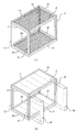
次に図面を参照して、本発明の好ましい実施の形態に係る木造建築物について詳細に説明する。図1は、本発明の好ましい実施の形態に係る木造建築物の1単位となる構造ユニット10を示した概略斜視図である。全体として直方体の形状に形作られている構造ユニット10は、四隅に設けられる柱12と、長辺方向において柱12の上端同士を接合する長辺方向天井梁14と、短辺方向において柱12の上端同士を接合する短辺方向天井梁16と、長辺方向において柱12の下端同士を接合する長辺方向床梁18と、短辺方向において柱12の下端同士を接合する短辺方向床梁20とを有している。
Next, with reference to drawings, the wooden building which concerns on preferable embodiment of this invention is demonstrated in detail. FIG. 1 is a schematic perspective view showing a
2本の柱12、長辺方向天井梁14及び長辺方向床梁18によって、一対の対向する第1面22(高さH1 )が構成され、2本の柱12、短辺方向天井梁16及び短辺方向床梁20によって、一対の対向する第2面24(高さH2 )が構成される(図2(b)参照)。なお、天井梁14、16及び床梁18、20の梁高が同じである場合には、H1 =H2となる。
The two
構造ユニット10は又、第1面22の面内において両方の柱12に隣接してそれぞれ配置される耐力壁パネル26と、第2面24の面内において両方の柱12に隣接してそれぞれ配置される第1耐力壁パネル26とを備えている。
The
図4(a)は合板を取り付ける前の第1耐力壁パネル26の枠体を示した正面図、図4(b)は図4(a)の斜視図、図4(c)は枠体に合板が取り付けられている状態を示した部分切り取り斜視図である。第1耐力壁パネル26は、図4(a)に示されるように、全体高さhが第1面22の高さH1 とほぼ等しくなるように形成された矩形の枠体28を有している。枠体28は、2本の縦材28a、28bと、縦材28a、28bの上端同士を接合する上横材28cと、縦材28a、28bの下端同士を接合する下横材28dとによって構成されており、縦材28aと上横材28c、及び縦材28aと下横材28dが後述する2個の接合金具30によってそれぞれ堅固に接合されている。
4A is a front view showing the frame of the first load-bearing
接合金具30は、図5に示されるように、中央で直角に折り曲げられた細長い鋼製の矩形板30aと、矩形板30aの各辺同士を連結する対向した2枚の直角三角形状の鋼製の側板30bとによって形成されている。矩形板30aの各部には、ほぼ中央に配置された第1孔30a1、第1孔30a1の両側に配置された第2孔30a2、及び各部の両端に沿って設けられた小孔30a3がそれぞれ設けられている。第1孔30a1は、後述するように、主として、構造ユニット10同士を接合する際にボルト(図示せず)を通すのに使用される。第2孔30a2は、後述するように、主として、耐力壁パネル26を柱12及び梁14、16、18、20に接合する際にボルト(図示せず)を通すのに使用される。小孔30a3は、接合金具30を枠体28に取り付ける際の釘孔として使用される。
As shown in FIG. 5, the joining
第1耐力壁パネル26の枠体28の両面には、合板28eが釘等(図示せず)で取り付けられる。
図6は、第2耐力壁パネル26′を示した図である(そのうち、図6(a)は合板を取り付ける前の第2耐力壁パネル26′の枠体を示した斜視図、図6(b)は枠体に合板が取り付けられている状態を示した部分切り取り斜視図である)。第2耐力壁パネル26′は、両方の縦材28a、28bの上端と下端において計4個の接合金具30が取り付けられている点を除いて、耐力壁パネル26と実質的に同一の構成を有している。すなわち、第2耐力壁パネル26′は、2本の縦材28a、28bと、縦材28a、28bの上端同士を接合する上横材28cと、縦材28a、28bの下端同士を接合する下横材28dとによって構成された矩形の枠体28を有しており、縦材28aと上横材28c、縦材28aと下横材28d、縦材28bと上横材28c、及び縦材28bと下横材28dが4個の接合金具30によってそれぞれ堅固に接合されている。
FIG. 6 is a view showing the second load-bearing
第2耐力壁パネル26′の枠体28の両面にも、第1耐力壁パネル26と同様に、合板28eが釘等(図示せず)で取り付けられる。
Similarly to the first load-bearing
なお、第1耐力壁パネル26と第2耐力壁パネル26′の使い分けについては、後述する。
The use of the first
第1耐力壁パネル26および第2耐力壁パネル26′は、以下のような2つの機能を有している。
(1)良好な遮音効果を提供する。
構造ユニット10同士を接合したり、第1耐力壁パネル26又は第2耐力壁パネル26′を柱や梁に接合したりする際、耐力壁パネル26、26′の枠体28や柱、梁に設けられた穴にボルトを通すことによって接合される。この際、作業のし易さを考慮して、ボルト径よりも大きな穴が枠体、柱、梁に開けられるのが一般的である。一方、木材は乾燥するので、施工時に設けられた穴が拡大しがちである(M16ボルトを使用する場合を例にとると、ボルト穴は通常、18mm〜21mmであり、乾燥すると、ボルト穴は、20mm〜23mm程度となる)。したがって、ボルト穴の隙間(上述の例では、4mm〜7mm程度の隙間が開くこととなる)から音が漏洩することが多いが、耐力壁パネル26、26′では、枠体28の両面に合板28eが取り付けられ、枠体28内が閉空間となっているので、ボルト穴からの音の漏洩を遮断することができる。
(2)強固な構造部材となる。
耐力壁パネル26、26′は、枠体28を構成する縦材28a、28bと上横材28c、下横材28dが接合金具30によって堅固に接合されており、かつ、枠体28の両面に合板28eが取り付けられているので、強固な構造部材として機能する。
The first
(1) Provide a good sound insulation effect.
When joining the
(2) It becomes a strong structural member.
In the load-
なお、図1には示されていないが、構造ユニット10の天井面、床面には根太が取り付けられ(図3(a)参照)、合板が貼られている(図3(b)参照)。また、壁面には間柱や梁が取り付けられ、合板が貼られており、所要箇所にドアやサッシ等が取り付けられている。さらに、壁面に外壁を貼り付け、内部の造作を行って、構造ユニット10が完成する。
Although not shown in FIG. 1, joists are attached to the ceiling surface and floor surface of the structural unit 10 (see FIG. 3A), and plywood is attached (see FIG. 3B). . In addition, studs and beams are attached to the wall surface, plywood is pasted, and doors, sashes, and the like are attached to required places. Further, the
上述の実施の形態では、構造ユニット10の立体フレームの長辺方向と短辺方向の両方向において両方の柱12に隣接して第1耐力壁パネル26又は第2耐力壁パネル26′がそれぞれ配置されているが、ドアや窓などを設置するための開口部を設ける必要がある等、特に短辺方向において2つの耐力壁パネルを配置する空間的余裕がない場合がある。そのような場合には、短辺方向において1つの耐力壁パネルを配置すれば足りるように構成してもよい(図7参照)。このような場合、短辺方向には、4個の接合金具30が用いられている第2耐力壁パネル26′を配置するのが好ましい。なお、接合金具30の取り付け状態を明瞭に示すため、図7では、内側の合板が図示されていない。
In the above-described embodiment, the first load-
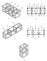
単一の構造ユニット10のみでも木造建築物として使用することができるが、複数の構造ユニット10を組み合わせることにより、種々の型式の木造建築物を形成することもできる。図8(a)は、短辺方向に4基の構造ユニット10を連結して形成される木造建築物を示した概略図、図8(b)は、図8(a)に示される木造建築物の平面図である。この例では、木造建築物全体の構造的強度を高めるため、4個の接合金具30が用いられている第2耐力壁パネル26′が木造建築物全体の四隅に配置されている。また、構造ユニット10の長辺方向の他の箇所には、第1耐力壁パネル26が配置されており、構造ユニット10の短辺方向の他の箇所には、第1耐力壁パネル26又は第2耐力壁パネル26′が配置されている(図8(a)、(b)に示される例では、短辺方向の2箇所に第2耐力壁パネル26′が配置され、短辺方向の他の箇所には第1耐力壁パネル26が配置されている)。図8(c)は、長辺方向に3基の構造ユニット10を連結して形成される木造建築物を示した概略図、図8(d)は、図8(c)に示される木造建築物の平面図である。この例では、木造建築物全体の構造的強度を高めるため、4個の接合金具30が用いられている第2耐力壁パネル26′が木造建築物全体の四隅に配置されている。また、構造ユニット10の長辺方向の他の箇所には、第1耐力壁パネル26が配置されており、構造ユニット10の短辺方向の他の箇所には、第1耐力壁パネル26又は第2耐力壁パネル26′が配置されている(図8(c)、(d)に示される例では、短辺方向の2箇所に第2耐力壁パネル26′が配置され、短辺方向の他の箇所には第1耐力壁パネル26が配置されている)。図8(e)は、垂直方向に2基の構造ユニット10を連結して形成される木造建築物を示した概略図である。これら図示した例以外にも、任意の組合せで種々の型式の木造建築物を形成することができる。なお、図8(a)〜図8(e)では、構造ユニット10の主要部を示すため、根太、合板、ドア、サッシ、外壁などは描かれていない。
Although only a single
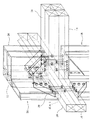
図9は、垂直方向に2基の構造ユニット10を連結して形成される木造建築物(図8(e)参照)において、構造ユニット10同士の連結状態を示した部分斜視図である。図9に示されるように、第1耐力壁パネル26の接合金具30の穴に通したボルトによって、構造ユニット10同士が強固に連結されているのが分かる。
FIG. 9 is a partial perspective view showing a connected state of the
次に、以上のように構成された木造建築物の施工方法について説明する。構造ユニット10を構成する各種部材(柱、梁、間柱、合板など)を所要の寸法に切断し、ほぞ取りや穴開け加工を施すとともに、梁に金物(根太受けなど)を取り付ける。一方、耐力壁パネル26を形成する。次いで、柱12、梁14、16、18、20を立方体形状に組み立てて、構造ユニット10の立体フレームを形成する。次いで、構造ユニット10の立体フレームの床と天井の下地組み(根太組み)作業を行い(図3(a)参照)、床と天井に合板を釘で取り付ける。次いで、第1面22及び第2面24の所定箇所に、耐力壁パネル26を取り付ける(図3(b)には、第1面22の一方に耐力壁パネル26を取り付けようとしている状態が示されている)。しかる後、外壁を貼り、内部の造作を行い、種々の配線/配管作業を行って、構造ユニット10が完成する。
Next, the construction method of the wooden building comprised as mentioned above is demonstrated. Various members (columns, beams, studs, plywood, etc.) constituting the
このようにして形成された構造ユニット10を現場に搬送し、土台を敷いた基礎上に設置し、構造ユニット同士を連結して、所要の木造建築物を形成する。図10は、構造ユニット10と土台を敷いた基礎との連結部の一例を示した図である。
The
本発明は、以上の発明の実施の形態に限定されることなく、特許請求の範囲に記載された発明の範囲内で、種々の変更が可能であり、それらも本発明の範囲内に包含されるものであることはいうまでもない。 The present invention is not limited to the above-described embodiments, and various modifications can be made within the scope of the invention described in the claims, and these are also included in the scope of the present invention. Needless to say, it is something.
10 構造ユニット
12 柱
14、16、18、20 梁
26 第1耐力壁パネル
26′ 第2耐力壁パネル
30 接合金具
DESCRIPTION OF
Claims (2)
前記構造ユニットが、四隅の柱と、長辺方向において前記柱の上端同士を接合する長辺方向天井梁と、短辺方向において前記柱の上端同士を接合する短辺方向天井梁と、長辺方向において前記柱の下端同士を接合する長辺方向床梁と、短辺方向において前記柱の下端同士を接合する短辺方向床梁とを有する立体フレームによって形成されており、
前記柱、前記長辺方向天井梁及び前記長辺方向床梁によって構成される対向する第1面の各面内において、両方の柱に隣接して第1耐力壁パネル又は第2耐力壁パネルがそれぞれ配置されており、
前記柱、前記短辺方向天井梁及び前記短辺方向床梁によって構成される対向する第2面の各面内において、両方の柱に隣接して第1耐力壁パネル又は第2耐力壁パネルがそれぞれ配置されており、
前記第1耐力壁パネルが、全体高さが前記第1面の高さとほぼ等しくなるように2本の縦材及び2本の横材で形成された矩形の枠体と、一方の縦材の上端及び下端において縦材と横材を堅固に接合する接合金具と、前記枠体の両面全体に取り付けられた合板とを有しており、
前記第2耐力壁パネルが、全体高さが前記第2面の高さとほぼ等しくなるように2本の縦材及び2本の横材で形成された矩形の枠体と、両方の縦材の上端及び下端において縦材と横材を堅固に接合する接合金具と、前記枠体の両面全体に取り付けられた合板とを有しており、
前記接合金具が、中央で直角に折り曲げられた細長い鋼製の矩形板と、前記矩形板の各辺同士を連結する対向した2枚の直角二等辺三角形状の鋼製の側板とによって形成され、前記矩形板の各部に、固定又は連結用の複数の穴が同じ数それぞれ設けられており、
前記接合金具に設けられた穴に締結具を通すことによって、前記耐力壁パネルを前記柱及び/又は梁に堅固に固定し、構造ユニット同士を堅固に連結し、或いは、構造ユニットを基礎に堅固に固定するように構成されていることを特徴とする木造建築物。 A wooden building formed by a single structural unit or a combination of multiple structural units,
The structural unit includes four corner columns, a long side ceiling beam that joins the upper ends of the columns in the long side direction, a short side direction ceiling beam that joins the upper ends of the columns in the short side direction, and a long side Formed by a three-dimensional frame having a long side floor beam that joins the lower ends of the columns in the direction and a short side floor beam that joins the lower ends of the columns in the short side direction;
Within each surface of the opposing first surface constituted by the column, the long side direction ceiling beam and the long side direction floor beam, a first load bearing wall panel or a second load bearing wall panel is adjacent to both columns. Each is arranged,
In each of the opposing second surfaces constituted by the columns, the short-side direction ceiling beams, and the short-side direction floor beams, a first load-bearing wall panel or a second load-bearing wall panel is adjacent to both columns. Each is arranged,
The first load-bearing wall panel has a rectangular frame formed of two vertical members and two cross members so that the overall height is substantially equal to the height of the first surface, and one vertical member It has a joining bracket that firmly joins the vertical member and the transverse member at the upper end and the lower end, and a plywood attached to both sides of the frame,
The second load-bearing wall panel has a rectangular frame formed of two vertical members and two cross members so that the overall height is substantially equal to the height of the second surface, and It has a joining bracket that firmly joins the vertical member and the transverse member at the upper end and the lower end, and a plywood attached to both sides of the frame,
The joining metal fitting is formed by an elongated steel rectangular plate bent at a right angle in the center, and two opposing right-angled isosceles triangular steel side plates connecting the sides of the rectangular plate, Each part of the rectangular plate is provided with the same number of fixing or connecting holes ,
By passing a fastener through a hole provided in the joint fitting, the load-bearing wall panel is firmly fixed to the pillar and / or beam, the structural units are firmly connected to each other, or the structural unit is firmly fixed on the basis. A wooden structure characterized in that it is configured to be fixed to.
前記構造ユニットが、四隅の柱と、長辺方向において前記柱の上端同士を接合する長辺方向天井梁と、短辺方向において前記柱の上端同士を接合する短辺方向天井梁と、長辺方向において前記柱の下端同士を接合する長辺方向床梁と、短辺方向において前記柱の下端同士を接合する短辺方向床梁とを有する立体フレームによって形成されており、
前記柱、前記長辺方向天井梁及び前記長辺方向床梁によって構成される対向する第1面の各面内において、両方の柱に隣接して第1耐力壁パネルがそれぞれ配置されており、
前記柱、前記短辺方向天井梁及び前記短辺方向床梁によって構成される対向する第2面の各面内において、一方の柱に隣接して第2耐力壁パネルがそれぞれ配置されており、
前記第1耐力壁パネルが、全体高さが前記第1面の高さとほぼ等しくなるように2本の縦材及び2本の横材で形成された矩形の枠体と、一方の縦材の上端及び下端において縦材と横材を堅固に接合する接合金具と、前記枠体の両面全体に取り付けられた合板とを有しており、
前記第2耐力壁パネルが、全体高さが前記第2面の高さとほぼ等しくなるように2本の縦材及び2本の横材で形成された矩形の枠体と、両方の縦材の上端及び下端において縦材と横材を堅固に接合する接合金具と、前記枠体の両面全体に取り付けられた合板とを有しており、
前記接合金具が、中央で直角に折り曲げられた細長い鋼製の矩形板と、前記矩形板の各辺同士を連結する対向した2枚の直角二等辺三角形状の鋼製の側板とによって形成され、前記矩形板の各部に、固定又は連結用の複数の穴が同じ数それぞれ設けられており、
前記接合金具に設けられた穴に締結具を通すことによって、前記耐力壁パネルを前記柱及び/又は梁に堅固に固定し、構造ユニット同士を堅固に連結し、或いは、構造ユニットを基礎に堅固に固定するように構成されていることを特徴とする木造建築物。 A wooden building formed by a single structural unit or a combination of multiple structural units,
The structural unit includes four corner columns, a long side ceiling beam that joins the upper ends of the columns in the long side direction, a short side direction ceiling beam that joins the upper ends of the columns in the short side direction, and a long side Formed by a three-dimensional frame having a long side floor beam that joins the lower ends of the columns in the direction and a short side floor beam that joins the lower ends of the columns in the short side direction;
In each surface of the opposing first surface constituted by the pillar, the long side direction ceiling beam and the long side direction floor beam, a first load bearing wall panel is disposed adjacent to both the pillars, respectively.
A second load-bearing wall panel is disposed adjacent to one of the columns in each of the opposing second surfaces constituted by the columns, the short-side direction ceiling beams, and the short-side direction floor beams,
The first load-bearing wall panel has a rectangular frame formed of two vertical members and two cross members so that the overall height is substantially equal to the height of the first surface, and one vertical member It has a joining bracket that firmly joins the vertical member and the transverse member at the upper end and the lower end, and a plywood attached to both sides of the frame,
The second load-bearing wall panel has a rectangular frame formed of two vertical members and two cross members so that the overall height is substantially equal to the height of the second surface, and It has a joining bracket that firmly joins the vertical member and the transverse member at the upper end and the lower end, and a plywood attached to both sides of the frame,
The joining metal fitting is formed by an elongated steel rectangular plate bent at a right angle in the center, and two opposing right-angled isosceles triangular steel side plates connecting the sides of the rectangular plate, Each part of the rectangular plate is provided with the same number of fixing or connecting holes ,
By passing a fastener through a hole provided in the joint fitting, the load-bearing wall panel is firmly fixed to the pillar and / or beam, the structural units are firmly connected to each other, or the structural unit is firmly fixed on the basis. A wooden structure characterized in that it is configured to be fixed to.
Priority Applications (1)
| Application Number | Priority Date | Filing Date | Title |
|---|---|---|---|
| JP2005364703A JP4386885B2 (en) | 2005-12-19 | 2005-12-19 | Wooden building |
Applications Claiming Priority (1)
| Application Number | Priority Date | Filing Date | Title |
|---|---|---|---|
| JP2005364703A JP4386885B2 (en) | 2005-12-19 | 2005-12-19 | Wooden building |
Publications (2)
| Publication Number | Publication Date |
|---|---|
| JP2007169895A JP2007169895A (en) | 2007-07-05 |
| JP4386885B2 true JP4386885B2 (en) | 2009-12-16 |
Family
ID=38296806
Family Applications (1)
| Application Number | Title | Priority Date | Filing Date |
|---|---|---|---|
| JP2005364703A Active JP4386885B2 (en) | 2005-12-19 | 2005-12-19 | Wooden building |
Country Status (1)
| Country | Link |
|---|---|
| JP (1) | JP4386885B2 (en) |
Cited By (3)
| Publication number | Priority date | Publication date | Assignee | Title |
|---|---|---|---|---|
| JP5830191B1 (en) * | 2015-04-24 | 2015-12-09 | 株式会社アーキビジョン二十一 | Metal fittings for transporting wooden buildings and methods for transporting wooden buildings using the metal fittings |
| JP6283443B1 (en) * | 2017-06-07 | 2018-02-21 | みやび建設株式会社 | Architectural connector, building forming unit, and building |
| JP6297738B1 (en) * | 2017-10-17 | 2018-03-20 | みやび建設株式会社 | Architectural connector, building forming unit, and building |
-
2005
- 2005-12-19 JP JP2005364703A patent/JP4386885B2/en active Active
Cited By (5)
| Publication number | Priority date | Publication date | Assignee | Title |
|---|---|---|---|---|
| JP5830191B1 (en) * | 2015-04-24 | 2015-12-09 | 株式会社アーキビジョン二十一 | Metal fittings for transporting wooden buildings and methods for transporting wooden buildings using the metal fittings |
| JP6283443B1 (en) * | 2017-06-07 | 2018-02-21 | みやび建設株式会社 | Architectural connector, building forming unit, and building |
| JP2018204367A (en) * | 2017-06-07 | 2018-12-27 | みやび建設株式会社 | Connector for construction, structure formation unit, and structure |
| JP6297738B1 (en) * | 2017-10-17 | 2018-03-20 | みやび建設株式会社 | Architectural connector, building forming unit, and building |
| JP2018204417A (en) * | 2017-10-17 | 2018-12-27 | みやび建設株式会社 | Connector for construction, structure formation unit, and structure |
Also Published As
| Publication number | Publication date |
|---|---|
| JP2007169895A (en) | 2007-07-05 |
Similar Documents
| Publication | Publication Date | Title |
|---|---|---|
| JP6403025B1 (en) | Steel column-beam joint structure and wooden structure | |
| JP2011202439A (en) | Building unit | |
| JP4386885B2 (en) | Wooden building | |
| JP3128720U (en) | Seismic opening frame using wooden members attached to a wooden frame | |
| JP5172607B2 (en) | Joint structure of flat column and beam | |
| JP5123603B2 (en) | Unit type building and construction method of unit type building | |
| JP2009030321A (en) | Portal frame by connection of composite beam and wooden pillar | |
| JPH1046664A (en) | Beam penetrative steel frame system | |
| JPH08246601A (en) | Wall panel and external wall structure | |
| JP4019166B2 (en) | Novel wall structure material for building and wall construction method using the wall structure material | |
| JP6860354B2 (en) | Building structure | |
| JP2020051182A (en) | Wall structure of temporary building | |
| JP2999102B2 (en) | Fire-resistant building units | |
| JP2774058B2 (en) | Three-storey unit building | |
| JP2948716B2 (en) | Wooden frame panel structure | |
| JP4839161B2 (en) | Wooden frame structure | |
| JP7096606B2 (en) | Wall structure, wooden building, and how to build a wooden building | |
| JP7323999B2 (en) | bearing wall | |
| JPH11141017A (en) | Structural member for two-by-four, connecting construction, and groundsill hardware | |
| JPH0525982B2 (en) | ||
| UA19436U (en) | Wall panel | |
| JP2002339483A (en) | Prefabricated bearing wall panel and construction method of building using the same | |
| JP2774059B2 (en) | Three-storey unit building | |
| JP2544869B2 (en) | Method of connecting frame member and panel and panel used for it | |
| JP2024048619A (en) | Wooden panel assembly building |
Legal Events
| Date | Code | Title | Description |
|---|---|---|---|
| A621 | Written request for application examination |
Free format text: JAPANESE INTERMEDIATE CODE: A621 Effective date: 20081113 |
|
| A871 | Explanation of circumstances concerning accelerated examination |
Free format text: JAPANESE INTERMEDIATE CODE: A871 Effective date: 20081114 |
|
| A975 | Report on accelerated examination |
Free format text: JAPANESE INTERMEDIATE CODE: A971005 Effective date: 20081215 |
|
| A131 | Notification of reasons for refusal |
Free format text: JAPANESE INTERMEDIATE CODE: A131 Effective date: 20081217 |
|
| A521 | Request for written amendment filed |
Free format text: JAPANESE INTERMEDIATE CODE: A523 Effective date: 20090210 |
|
| A131 | Notification of reasons for refusal |
Free format text: JAPANESE INTERMEDIATE CODE: A131 Effective date: 20090519 |
|
| TRDD | Decision of grant or rejection written | ||
| A01 | Written decision to grant a patent or to grant a registration (utility model) |
Free format text: JAPANESE INTERMEDIATE CODE: A01 Effective date: 20090928 |
|
| A01 | Written decision to grant a patent or to grant a registration (utility model) |
Free format text: JAPANESE INTERMEDIATE CODE: A01 |
|
| A61 | First payment of annual fees (during grant procedure) |
Free format text: JAPANESE INTERMEDIATE CODE: A61 Effective date: 20090929 |
|
| R150 | Certificate of patent or registration of utility model |
Ref document number: 4386885 Country of ref document: JP Free format text: JAPANESE INTERMEDIATE CODE: R150 Free format text: JAPANESE INTERMEDIATE CODE: R150 |
|
| FPAY | Renewal fee payment (event date is renewal date of database) |
Free format text: PAYMENT UNTIL: 20121009 Year of fee payment: 3 |
|
| FPAY | Renewal fee payment (event date is renewal date of database) |
Free format text: PAYMENT UNTIL: 20121009 Year of fee payment: 3 |
|
| FPAY | Renewal fee payment (event date is renewal date of database) |
Free format text: PAYMENT UNTIL: 20131009 Year of fee payment: 4 |
|
| R250 | Receipt of annual fees |
Free format text: JAPANESE INTERMEDIATE CODE: R250 |
|
| R250 | Receipt of annual fees |
Free format text: JAPANESE INTERMEDIATE CODE: R250 |
|
| R250 | Receipt of annual fees |
Free format text: JAPANESE INTERMEDIATE CODE: R250 |
|
| R250 | Receipt of annual fees |
Free format text: JAPANESE INTERMEDIATE CODE: R250 |
|
| R250 | Receipt of annual fees |
Free format text: JAPANESE INTERMEDIATE CODE: R250 |
|
| R250 | Receipt of annual fees |
Free format text: JAPANESE INTERMEDIATE CODE: R250 |
|
| R250 | Receipt of annual fees |
Free format text: JAPANESE INTERMEDIATE CODE: R250 |
|
| R250 | Receipt of annual fees |
Free format text: JAPANESE INTERMEDIATE CODE: R250 |
|
| R250 | Receipt of annual fees |
Free format text: JAPANESE INTERMEDIATE CODE: R250 |
|
| R250 | Receipt of annual fees |
Free format text: JAPANESE INTERMEDIATE CODE: R250 |
|
| R250 | Receipt of annual fees |
Free format text: JAPANESE INTERMEDIATE CODE: R250 |