JP4384342B2 - Assembly for housing an inflatable airbag and method of production thereof - Google Patents
Assembly for housing an inflatable airbag and method of production thereof Download PDFInfo
- Publication number
- JP4384342B2 JP4384342B2 JP2000249009A JP2000249009A JP4384342B2 JP 4384342 B2 JP4384342 B2 JP 4384342B2 JP 2000249009 A JP2000249009 A JP 2000249009A JP 2000249009 A JP2000249009 A JP 2000249009A JP 4384342 B2 JP4384342 B2 JP 4384342B2
- Authority
- JP
- Japan
- Prior art keywords
- section
- trim
- liner
- margin
- seam
- Prior art date
- Legal status (The legal status is an assumption and is not a legal conclusion. Google has not performed a legal analysis and makes no representation as to the accuracy of the status listed.)
- Expired - Lifetime
Links
Images


Classifications
-
- B—PERFORMING OPERATIONS; TRANSPORTING
- B60—VEHICLES IN GENERAL
- B60R—VEHICLES, VEHICLE FITTINGS, OR VEHICLE PARTS, NOT OTHERWISE PROVIDED FOR
- B60R21/00—Arrangements or fittings on vehicles for protecting or preventing injuries to occupants or pedestrians in case of accidents or other traffic risks
- B60R21/02—Occupant safety arrangements or fittings, e.g. crash pads
- B60R21/16—Inflatable occupant restraints or confinements designed to inflate upon impact or impending impact, e.g. air bags
- B60R21/20—Arrangements for storing inflatable members in their non-use or deflated condition; Arrangement or mounting of air bag modules or components
- B60R21/207—Arrangements for storing inflatable members in their non-use or deflated condition; Arrangement or mounting of air bag modules or components in vehicle seats
-
- B—PERFORMING OPERATIONS; TRANSPORTING
- B60—VEHICLES IN GENERAL
- B60R—VEHICLES, VEHICLE FITTINGS, OR VEHICLE PARTS, NOT OTHERWISE PROVIDED FOR
- B60R21/00—Arrangements or fittings on vehicles for protecting or preventing injuries to occupants or pedestrians in case of accidents or other traffic risks
- B60R21/02—Occupant safety arrangements or fittings, e.g. crash pads
- B60R21/16—Inflatable occupant restraints or confinements designed to inflate upon impact or impending impact, e.g. air bags
- B60R2021/161—Inflatable occupant restraints or confinements designed to inflate upon impact or impending impact, e.g. air bags characterised by additional means for controlling deployment trajectory
Abstract
Description
【0001】
【発明の属する技術分野】
本発明は一般に、膨張可能エアバッグを収容するためのアセンブリ及びその生産方法に関する。より詳細には、本発明は、膨張可能エアバッグの力をトリム・カバー内で特定のシームの方向に向けるためのキャビティ・ライナを含み、それにより特定のシームを介する膨張可能エアバッグの展開に対処するアセンブリに関する。
【0002】
【従来の技術】
近年、自動車製造業者は、車両搭乗者用の改善された側部衝撃保護を提供することにますます注意を向けるようになってきている。実行可能な方法の1つには、搭乗者シートのシート・バック・フレームに取り付けられる膨張可能エアバッグを提供することが含まれる。シート取付型側部衝撃膨張可能エアバッグ(SIAB)は、2つの全般的なカテゴリに入る。シート取付型SIABの第1のタイプは、シート・バックまたはシート・クッション・ボルスタの外側にある目に見える個別のドアから展開する。シート取付型SIABのもう一方のタイプは、シート・トリムの下に詰め込まれ、トリム・カバーを介して展開するように設計されている。
【0003】
いくつかの面で、第1のタイプは、個別のドアを介するエアバッグの展開に関する技術がハンドルおよび計器板内にある前部エアバッグについてすでに開発されているという利点を有する。しかし、第1のタイプは、SIABの位置が一般にシートの側部に限定され、そのため目に見えるドアがシート占有者によって係合されるシート表面の一部でないという欠点を有する。エアバッグが、ボルスタ・シームの位置などシート・バックの前部隅を介して展開することが望ましい場合、シート取付型SIABの第1のタイプを使用することができない。一方、シート取付型SIABの第2のタイプは、エアバッグがシートの座り心地に悪影響を及ぼさないように、典型的にはトリム・カバーおよびフォームド・パディング(foamed padding)の下で使用しなければならない。
【0004】
シート取付型側部衝撃エアバッグの第2のタイプに関する近年の開発の1つとしては、エアバッグの力を特定のシームの方向に向けるためのキャビティ・ライナを使用することがある。しかし、キャビティ・ライナの欠点の1つは、キャビティ・ライナが通常、搭乗者シートのシート・バッグ用のトリム・カバー内にトップステッチされることである。シート・バックの前部隅は、搭乗者シートの最もよく目に見える面の1つであり、ボルスタ・シームでのトップステッチは、高価な自動車の購入を考えている人に、見た目の悪い特徴と見なされる。したがって、搭乗者シートのボルスタ・シーム内に、目に見えるトップステッチがないシート取付型側部衝撃エアバッグを提供する必要がある。
【0005】
【発明が解決しようとする課題】
したがって、本発明は、当技術分野の従来技法の問題および欠点を克服する膨張可能エアバッグ・モジュールを収容するためのアセンブリを提供する。本発明はまた、膨張可能エアバッグ用の見た目の良いハウジングを提供するアセンブリを提供する。
【0006】
【課題を解決するための手段】
簡単に言うと、本発明のアセンブリは、車両の構成要素を覆うための2セクション・トリム・カバーを含む。トリム・セクションの外側表面が互いに固定され、それによりプレーン・シームを形成し、トリム・カバーのマージン部分は、外側表面の内側に折り返される。アセンブリはさらに、膨張可能エアバッグの力をプレーン・シームの方向に向けるための2セクション・キャビティ・ライナを含む。トリム・カバーのマージン部分がプレーン・シームを阻止しないように、トリム・カバーのマージン部分はライナ・セクションに固定される。しかし、トリム・カバーのマージン部分は、トリム・カバーの外側表面を実質的に貫通せずに、ライナ・セクションに固定される。このため、縫い付けがトリム・カバーの外側表面に面する地点(vantage)から実質的に隠されているとき、アセンブリは、膨張可能エアバッグに関して見た目の良いハウジングを提供する。
【0007】
本発明のさらなる特徴および利点は、以下の考察および添付図面から明らかになる。
【0008】
【発明の実施の形態】
第1および第2の好ましい実施形態、ならびに第1および第2の好ましい方法の以下の説明は、その性質上、例示的なものにすぎず、本発明、またはその適用例もしくは使用法を限定するものでは決してない。
【0009】
図1に示されるように、アセンブリ10は、搭乗者シート12の内部シート・バック・フレームを覆う働きをし、かつ搭乗者シート12内に隠され、シート・バック・フレームに取り付けられた膨張可能エアバッグ・モジュールを収容する働きをする。ただし、アセンブリ10は、車両の他の構成要素、例えばダッシュボード、ヘッドライナ、ルーフ・ピラー、コンソール、または任意の他の適切な構成要素を覆うために使用することもできる。
【0010】
図2に示されるように、本発明の好ましい実施形態のアセンブリ10は、トリム・カバー14と、膨張可能エアバッグ・モジュール16と、キャビティ・ライナ18とを含む。トリム・カバー14は、第1のトリム・セクション20および第2のトリム・セクション22を含む。トリム・セクション20と22は共に、革、布、ビニールなどの耐久性材料からなる外側表面24および26と、フォームド・パディングなどより柔軟な材料からなる内側表面28および30とを有する。第1のトリム・セクション20は、第1のシーム32によって第2のトリム・セクション22に固定される。プレーン・シーム32は従来のステッチであり、別法としては、接着剤、スナップ、ステープル、VELCRO(登録商標)、DUAL−LOCK(登録商標)など他のファスナであってよい。プレーン・シーム32を使用するとき、トリム・セクション20および22は内側に折り返され、第1のトリム・セクション20の外側表面24が第2のトリム・セクション22の外側表面26に接触する。プレーン・シーム32は、トリム・セクション20および22を、本体部分34および36と、マージン部分38および40とに分ける。本体部分34および36の外側表面24および26は車両の搭乗者に見えるようになっているが、本体部分34および36の内側表面28および30と、マージン部分38および40の全体とは隠されている。
【0011】
膨張可能エアバッグ・モジュール16は、車両の搭乗者と車両の表面との間にエアバッグ(図示せず)を急速に膨張させることによって、車両の衝撃の激しさを軽減する働きをする。膨張可能エアバッグ・モジュール16は、従来の側部衝撃エアバッグ・モジュールである。膨張可能エアバッグ・モジュール16は、ファスナ42によってシート・バック・フレーム(図示せず)に接続する。ファスナ42は、スタッドとナットを含むことが好ましいが、当業者に理解されるように、他の適切なファスナを使用することもできる。他の適用例では、膨張可能エアバッグ・モジュール16を、ダッシュボード構造部材、ルーフ部分、ルーフ・ピラー、または車両の任意の他の適切な構造要素に固定することができる。膨張可能エアバッグ・モジュールは、膨張可能エアバッグ・システムの技術分野で知られており、使用され、膨張可能モジュール16のアセンブリ10への実施は、当業者には容易に理解されよう。
【0012】
エアバッグは、膨張すると体積を急速に増大し、トリム・カバー14を押圧する。トリム・カバー14を介するエアバッグの展開に対処するため、本発明のキャビティ・ライナ18は、エアバッグの力を第1のシーム32の方向へ向ける。キャビティ・ライナ18は、第1のライナ・セクション44および第2のライナ・セクション46を含む。第1のライナ・セクション44は、プレーン・シーム32で第1のトリム・セクション20に固定され、第2のライナ・セクション46は、プレーン・シーム32で第2のトリム・セクション22に固定される。このようにして、プレーン・シーム32はさらに、ライナ・セクション44および46を、本体部分48および50と、マージン部分52および54とに分ける。膨張可能エアバッグの力をプレーン・シームに向けるため、マージン部分38、40、52、および54は、キャビティ・ライナ18の本体部分48および50に固定される。第1のライナ・セクション44のマージン部分52、および第1のトリム・セクション20のマージン部分38は、第1のマージン・シーム56によって第1のライナ・セクション44の本体部分48に固定される。同様に、第2のライナ・セクション46のマージン部分54、および第2のトリム・セクション22のマージン部分40は、第2のマージン・シーム58によって第2のライナ・セクション46の本体部分50に固定される。プレーン・シーム32と同様に、マージン・シーム56および58は従来のステッチであり、別法としては、接着剤、スナップ、ステープル、VELCRO(登録商標)、DUAL−LOCK(登録商標)など他のファスナであってよい。しかし、マージン・シーム56と58は共に、トリム・カバー14の外側表面24および26を貫通しない。換言すると、マージン・シーム56および58は、トリム・カバー14の外側表面24および26に面する地点から実質的に隠されている。このため、アセンブリ10は、膨張可能エアバッグ用の見た目の良いハウジングを提供する。
【0013】
第1のライナ・セクション44および第2のライナ・セクション46は、420、630、または840デニール・ナイロンや、ポリエステル・エアバッグ繊維など実質的に非弾性の材料、または他の適切な材料からなる。後部シーム60は、第1のライナ・セクション44と第2のライナ・セクション46を互いに固定する。製造面ではより困難になるが、第1のライナ・セクション44を、第2のライナ・セクション46と共に1部片キャビティ・ライナ(図示せず)に一体形成することもできる。
【0014】
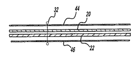
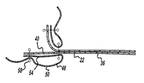
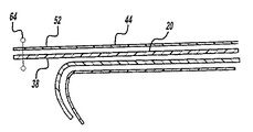
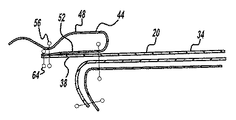
本発明の第1の好ましい実施形態のアセンブリ10は、以下の4つの全般的なステップによって生産することができる。(1)第1のトリム・セクション20および第2のトリム・セクション22を提供し、かつ第1のライナ・セクション44および第2のライナ・セクション46を提供するステップ。(2)図3に示されるように、第1のライナ・セクション44と、第1のトリム・セクション20と、第2のトリム・セクション22と、第2のライナ・セクション46とを通してプレーン・シーム32を縫い付けるステップ。(3)図4に示されるように、第1のライナ・セクション44の本体部分48を第1のライナ・セクション44のマージン部分52の上に折り返し、縫い付けによって第1のトリム・セクション20の本体部分34を実質的に貫通せずに、第1のライナ・セクション44の本体部分48と、第1のトリム・セクション20のマージン部分38とを通して第1のマージン・シーム56を縫い付けるステップ。(4)図5に示されるように、第2のライナ・セクション46の本体部分50を第2のライナ・セクション46のマージン部分54の上に折り返し、縫い付けによって第2のトリム・セクション22の本体部分36を実質的に貫通することなく、第2のライナ・セクション46の本体部分50と、第2のトリム・セクション22のマージン部分40とを通して第2のマージン・シーム58を縫い付けるステップ。図6に示される最終的な形で、アセンブリ10は膨張可能エアバッグ(図示せず)を収容することができる。
【0015】
本発明の第1の好ましい方法では、ステップ1から4を番号順に続ける。代替方法では、ステップ1から4を異なる順序で続けることができる。
【0016】
図7に示されるように、本発明の第2の好ましい実施形態のアセンブリ62は、第1のマイナ・タック64および第2のマイナ・タック66を含む。マイナ・タック64および66は、トリム・カバー14のマージン部分38および40を、キャビティ・ライナ18のマージン部分52および54に固定する働きをする。プレーン・シーム32、ならびにマージン・シーム56および58と同様に、マイナ・タック64および66は従来のステッチであり、別法としては、接着剤、スナップ、ステープル、VELCRO(登録商標)、DUAL−LOCK(登録商標)など他のファスナであってよい。他の全ての態様では、第2の好ましい実施形態のアセンブリ62は、第1の好ましい実施形態のアセンブリ10と同様に働く。このため、図2の要素は、図7と同じ参照符号で示される。
【0017】
第2の好ましい実施形態のアセンブリ62を生産する第2の好ましい方法は、本発明の第1の好ましい方法に関して上述したステップ1とステップ2の間で行われる追加のステップを含む。追加のステップは、図8に示されるように、第1のライナ・セクション44のマージン部分52と、第1のトリム・セクション20のマージン部分38とを通して第1のマイナ・タック64を縫い付けることを含む。図9に示されるように、追加のステップはさらに、第2のライナ・セクション46のマージン部分54と、第2のトリム・セクション22のマージン部分40とを通して第2のマイナ・タック66を縫い付けることを含む。追加のステップは、マージン部分52および54をマージン部分38および40と位置合わせする働きをする。他の全ての態様で、図10、11、および12に示されるステップ2、3、および4は、図3、4、および5に示されるステップ2、3、および4と同様である。さらに、他の全ての態様で、図13に示される第2の好ましい実施形態のアセンブリ62は、図6に示される第1の好ましい実施形態のアセンブリ10と同様である。このため、図8〜13の要素は、図3〜6と同じ参照符号で示されている。
【0018】
前述の考察は、本発明の好ましい実施形態および方法を開示し、記述する。そのような考察、ならびに添付図面および特許請求の範囲から、頭記の特許請求の範囲に定義された本発明の真の精神および公正な範囲から逸脱することなく本発明に変更および修正を加えることができることを当業者は容易に理解されよう。
【図面の簡単な説明】
【図1】本発明の第1の好ましい実施形態によるアセンブリを備える搭乗者シートの斜視図である。
【図2】図1の線2−2に沿って取られた、本発明の第1の好ましい実施形態によるアセンブリの断面図である。
【図3】本発明の第1の好ましい方法によるアセンブリを生産するための1ステップの側面図である。
【図4】本発明の第1の好ましい方法によるアセンブリを生産するための1ステップの側面図である。
【図5】本発明の第1の好ましい方法によるアセンブリを生産するための1ステップの側面図である。
【図6】本発明の第1の好ましい方法によるアセンブリを生産するための1ステップの側面図である。
【図7】本発明の第2の好ましい実施形態によるアセンブリの断面図である。
【図8】本発明の第2の好ましい方法によるアセンブリを生産するための1ステップの側面図である。
【図9】本発明の第2の好ましい方法によるアセンブリを生産するための1ステップの側面図である。
【図10】本発明の第2の好ましい方法によるアセンブリを生産するための1ステップの側面図である。
【図11】本発明の第2の好ましい方法によるアセンブリを生産するための1ステップの側面図である。
【図12】本発明の第2の好ましい方法によるアセンブリを生産するための1ステップの側面図である。
【図13】本発明の第2の好ましい方法によるアセンブリを生産するための1ステップの側面図である。
【符号の説明】
10 アセンブリ
12 搭乗者シート
14 トリム・カバー
16 膨張可能エアバッグ・モジュール
18 キャビティ・ライナ
20、22 トリム・セクション
24、26 外側表面
28、30 内側表面
32、60 シーム
34、36、48、50 本体部分
38、40、52、54 マージン部分
42 ファスナ
44、46 ライナ・セクション
56、58 マージン・シーム[0001]
BACKGROUND OF THE INVENTION
The present invention generally relates to an assembly for containing an inflatable airbag and a method for producing the same. More particularly, the present invention includes a cavity liner for directing the force of an inflatable airbag toward a specific seam within the trim cover, thereby enabling deployment of the inflatable airbag via a specific seam. The assembly to deal with.
[0002]
[Prior art]
In recent years, automobile manufacturers have increasingly turned their attention to providing improved side impact protection for vehicle occupants. One feasible method includes providing an inflatable airbag that is attached to the seat back frame of the passenger seat. Seat mounted side impact inflatable airbags (SIABs) fall into two general categories. The first type of seat mounted SIAB deploys from a separate visible door outside the seat back or seat cushion bolster. The other type of seat mounted SIAB is designed to be packed under the seat trim and deployed through the trim cover.
[0003]
In some aspects, the first type has the advantage that techniques for deploying airbags through individual doors have already been developed for the front airbags in the handle and instrument panel. However, the first type has the disadvantage that the position of the SIAB is generally limited to the side of the seat so that the visible door is not part of the seat surface engaged by the seat occupant. The first type of seat mounted SIAB cannot be used if it is desirable for the airbag to be deployed through the front corners of the seat back, such as the location of a bolster seam. On the other hand, the second type of seat-mounted SIAB typically must be used under a trim cover and foamed padding so that the airbag does not adversely affect seat comfort. I must.
[0004]
One recent development for the second type of seat-mounted side impact airbag is to use a cavity liner to direct the airbag force toward a specific seam. However, one of the drawbacks of cavity liners is that the cavity liner is usually topstitched in the passenger seat seat bag trim cover. The front corner of the seat back is one of the most visible aspects of the passenger seat, and the top stitching at the bolster seam is a bad looking feature for those considering buying expensive cars Is considered. Accordingly, there is a need to provide a seat-mounted side impact airbag that does not have a visible top stitch in the bolster seam of the passenger seat.
[0005]
[Problems to be solved by the invention]
Accordingly, the present invention provides an assembly for housing an inflatable airbag module that overcomes the problems and disadvantages of the prior art in the art. The present invention also provides an assembly that provides a pleasing housing for an inflatable airbag.
[0006]
[Means for Solving the Problems]
Briefly, the assembly of the present invention includes a two-section trim cover for covering vehicle components. The outer surfaces of the trim sections are secured together, thereby forming a plain seam, and the margin portion of the trim cover is folded inside the outer surface. The assembly further includes a two-section cavity liner for directing the force of the inflatable airbag toward the plain seam. The trim cover margin is secured to the liner section so that the trim cover margin does not block the plain seam. However, the margin portion of the trim cover is secured to the liner section without substantially penetrating the outer surface of the trim cover. Thus, when the seam is substantially hidden from the vantage facing the outer surface of the trim cover, the assembly provides a aesthetic housing for the inflatable airbag.
[0007]
Further features and advantages of the present invention will become apparent from the following discussion and the accompanying drawings.
[0008]
DETAILED DESCRIPTION OF THE INVENTION
The following descriptions of the first and second preferred embodiments and the first and second preferred methods are merely exemplary in nature and limit the invention or its applications or uses. It is never a thing.
[0009]
As shown in FIG. 1, the
[0010]
As shown in FIG. 2, the
[0011]
The inflatable airbag module 16 serves to reduce the severity of vehicle impact by rapidly inflating an airbag (not shown) between the vehicle occupant and the vehicle surface. The inflatable airbag module 16 is a conventional side impact airbag module. The inflatable airbag module 16 is connected to a seat back frame (not shown) by fasteners 42. Fasteners 42 preferably include studs and nuts, but other suitable fasteners may be used as will be appreciated by those skilled in the art. In other applications, the inflatable airbag module 16 can be secured to a dashboard structural member, roof portion, roof pillar, or any other suitable structural element of the vehicle. Inflatable airbag modules are known and used in the art of inflatable airbag systems, and implementation of the inflatable module 16 to the
[0012]
When inflated, the airbag rapidly increases in volume and presses the trim cover 14. To address deployment of the air bag through the trim cover 14, the cavity liner 18 of the present invention directs the force of the air bag toward the
[0013]
The
[0014]
The
[0015]
In the first preferred method of the present invention, steps 1 to 4 are continued in numerical order. In an alternative method, steps 1 to 4 can be continued in a different order.
[0016]
As shown in FIG. 7, the
[0017]
The second preferred method of producing the
[0018]
The foregoing discussion discloses and describes the preferred embodiments and methods of the present invention. From such considerations and the accompanying drawings and claims, changes and modifications may be made to the present invention without departing from the true spirit and fair scope of the invention as defined in the appended claims. Those skilled in the art will readily understand that this is possible.
[Brief description of the drawings]
FIG. 1 is a perspective view of an occupant seat comprising an assembly according to a first preferred embodiment of the present invention.
2 is a cross-sectional view of the assembly according to the first preferred embodiment of the present invention taken along line 2-2 of FIG.
FIG. 3 is a side view of one step for producing an assembly according to the first preferred method of the present invention.
FIG. 4 is a side view of one step for producing an assembly according to the first preferred method of the present invention.
FIG. 5 is a side view of one step for producing an assembly according to the first preferred method of the present invention.
FIG. 6 is a side view of one step for producing an assembly according to the first preferred method of the present invention.
FIG. 7 is a cross-sectional view of an assembly according to a second preferred embodiment of the present invention.
FIG. 8 is a side view of one step for producing an assembly according to the second preferred method of the present invention.
FIG. 9 is a side view of one step for producing an assembly according to the second preferred method of the present invention.
FIG. 10 is a side view of one step for producing an assembly according to the second preferred method of the present invention.
FIG. 11 is a side view of one step for producing an assembly according to the second preferred method of the present invention.
FIG. 12 is a side view of one step for producing an assembly according to the second preferred method of the present invention.
FIG. 13 is a side view of one step for producing an assembly according to the second preferred method of the present invention.
[Explanation of symbols]
10
Claims (15)
膨張可能エアバッグと、
前記膨張可能エアバッグの力を前記プレーン・シームの方向に向けるためのキャビティ・ライナとを備え、
前記キャビティ・ライナは、第1のライナ・セクションおよび第2のライナ・セクションを有し、前記第1のライナ・セクションが前記プレーン・シームで前記第1のトリム・セクションに固定され、前記プレーン・シームが前記第1のライナ・セクションの本体部分およびマージン部分を画定し、前記第1のトリム・セクションの前記マージン部分が第1のマイナ・タックで前記第1のライナ・セクションの前記マージン部分に固定され、前記第2のライナ・セクションが前記プレーン・シームで前記第2のトリム・セクションに固定され、前記プレーン・シームが前記第2のライナ・セクションの本体部分およびマージン部分を画定し、前記第2のトリム・セクションの前記マージン部分が第2のマイナ・タックで前記第2のライナ・セクションの前記マージン部分に固定され、
前記第1のトリム・セクションの前記マージン部分は、前記第1のマイナ・タックと前記プレーン・シームとの間で前記第1のライナ・セクションの前記本体部分に固定され、それにより前記第1のトリム・セクションの前記本体部分の前記外側表面を実質的に貫通せずに第1のマージン・シームを形成し、
前記第2のトリム・セクションの前記マージン部分は、前記第2のマイナ・タックと前記プレーン・シームとの間で前記第2のライナ・セクションの前記本体部分に固定され、それにより前記第2のトリム・セクションの前記本体部分の前記外側表面を実質的に貫通せずに第2のマージン・シームを形成するアセンブリ。An assembly for containing an inflatable airbag, a trim cover for covering a vehicle component, comprising a first trim section and a second trim section, wherein the first trim section A trim section has an outer surface and an inner surface, the second trim section has an outer surface and an inner surface, and the outer surface of the first trim section is the second trim section Fixed to the outer surface of the first trim section, thereby forming a plain seam, the plain seam defining a body portion and a margin portion of the first trim section, and a body of the second trim section A trim cover defining a portion and a margin portion;
An inflatable airbag;
A cavity liner for directing the force of the inflatable airbag toward the plain seam;
The cavity liner has a first liner section and a second liner section, wherein the first liner section is secured to the first trim section with the plain seam, A seam defines a body portion and a margin portion of the first liner section, and the margin portion of the first trim section is connected to the margin portion of the first liner section with a first minor tack. The second liner section is secured to the second trim section with the plain seam, the plain seam defining a body portion and a margin portion of the second liner section; The margin portion of the second trim section is a second minor tack and the second liner center Is secured to said margin portion of Deployment,
The margin portion of the first trim section is secured to the body portion of the first liner section between the first minor tack and the plain seam, whereby the first trim section Forming a first margin seam without substantially penetrating the outer surface of the body portion of the trim section;
The margin portion of the second trim section is secured to the body portion of the second liner section between the second minor tack and the plain seam, whereby the second trim section An assembly that forms a second margin seam without substantially penetrating the outer surface of the body portion of the trim section.
膨張可能エアバッグの力を前記プレーン・シームの方向に向けるためのキャビティ・ライナとを備え、
前記キャビティ・ライナは、第1のライナ・セクションおよび第2のライナ・セクションを有し、前記第1のライナ・セクションが前記プレーン・シームで前記第1のトリム・セクションに固定され、前記プレーン・シームが前記第1のライナ・セクションの本体部分およびマージン部分を画定し、前記第2のライナ・セクションが前記プレーン・シームで前記第2のトリム・セクションに固定され、前記プレーン・シームが前記第2のライナ・セクションの本体部分およびマージン部分を画定し、
前記第1のトリム・セクションの前記マージン部分が、前記第1のトリム・セクションの前記本体部分の前記外側表面を実質的に貫通せずに前記第1のライナ・セクションの前記本体部分に固定され、前記第2のトリム・セクションの前記マージン部分が、前記第2のトリム・セクションの前記本体部分の前記外側表面を実質的に貫通せずに前記第2のライナ・セクションの前記本体部分に固定されるアセンブリ。An assembly for containing an inflatable airbag, a trim cover for covering a vehicle component, comprising a first trim section and a second trim section, wherein the first trim section The trim section has an outer surface and an inner surface, the second trim section has an outer surface and an inner surface, and the outer surface of the first trim section is the second trim section. Secured to the outer surface, thereby forming a plain seam, the plain seam defining a body portion and a margin portion of the first trim section, and a body portion of the second trim section; and A trim cover defining a margin portion;
A cavity liner for directing the force of the inflatable airbag toward the plain seam;
The cavity liner has a first liner section and a second liner section, wherein the first liner section is secured to the first trim section with the plain seam, A seam defines a body portion and a margin portion of the first liner section, the second liner section is secured to the second trim section with the plain seam, and the plain seam is the first seam. Defining the body portion and margin portion of the two liner sections;
The margin portion of the first trim section is secured to the body portion of the first liner section without substantially penetrating the outer surface of the body portion of the first trim section. The margin portion of the second trim section is secured to the body portion of the second liner section without substantially penetrating the outer surface of the body portion of the second trim section. Assembly.
(a)第1のトリム・セクションおよび第2のトリム・セクションを有するトリム・カバーを提供し、かつ第1のライナ・セクションおよび第2のライナ・セクションを有するキャビティ・ライナを提供するステップと、
(b)第1のライナ・セクションと、第1のトリム・セクションと、第2のトリム・セクションと、第2のライナ・セクションとを通してプレーン・シームを縫い付けるステップであって、プレーン・シームが、第1のライナ・セクションと、第1のトリム・セクションと、第2のトリム・セクションと、第2のライナ・セクションとの本体部分およびマージン部分を画定するステップと、
(c)第1のライナ・セクションの本体部分を第1のライナ・セクションのマージン部分の上に折り返し、第1のトリム・セクションの本体部分を実質的に貫通せずに、第1のライナ・セクションの本体部分と、第1のトリム・セクションのマージン部分とを通して第1のマージン・シームを縫い付けるステップと、
(d)第2のライナ・セクションの本体部分を第2のライナ・セクションのマージン部分の上に折り返し、第2のトリム・セクションの本体部分を実質的に貫通せずに、第2のライナ・セクションの本体部分と、第2のトリム・セクションのマージン部分とを通して第2のマージン・シームを縫い付けるステップとを含む方法。A method for producing an assembly for containing an inflatable airbag comprising:
(A) providing a trim cover having a first trim section and a second trim section and providing a cavity liner having a first liner section and a second liner section;
(B) sewing a plain seam through the first liner section, the first trim section, the second trim section, and the second liner section, wherein the plain seam is Defining a body portion and a margin portion of the first liner section, the first trim section, the second trim section, and the second liner section;
(C) folding the body portion of the first liner section over the margin portion of the first liner section so that the first liner section does not substantially penetrate the body portion of the first trim section; Sewing a first margin seam through the body portion of the section and the margin portion of the first trim section;
(D) folding the body portion of the second liner section over the margin portion of the second liner section and substantially not penetrating the body portion of the second trim section; Sewing the second margin seam through the body portion of the section and the margin portion of the second trim section.
Applications Claiming Priority (2)
| Application Number | Priority Date | Filing Date | Title |
|---|---|---|---|
| US09/356,781 US6206410B1 (en) | 1999-07-16 | 1999-07-16 | Assembly for housing an inflatable airbag |
| US356781 | 1999-07-16 |
Publications (2)
| Publication Number | Publication Date |
|---|---|
| JP2001088649A JP2001088649A (en) | 2001-04-03 |
| JP4384342B2 true JP4384342B2 (en) | 2009-12-16 |
Family
ID=23402930
Family Applications (1)
| Application Number | Title | Priority Date | Filing Date |
|---|---|---|---|
| JP2000249009A Expired - Lifetime JP4384342B2 (en) | 1999-07-16 | 2000-07-14 | Assembly for housing an inflatable airbag and method of production thereof |
Country Status (5)
| Country | Link |
|---|---|
| US (1) | US6206410B1 (en) |
| EP (1) | EP1069004B1 (en) |
| JP (1) | JP4384342B2 (en) |
| AT (1) | ATE316022T1 (en) |
| DE (1) | DE60025555T2 (en) |
Families Citing this family (52)
| Publication number | Priority date | Publication date | Assignee | Title |
|---|---|---|---|---|
| FR2830817B1 (en) * | 2001-10-11 | 2004-01-30 | Peugeot Citroen Automobiles Sa | MOTOR VEHICLE SEAT COMPRISING AN INFLATABLE BAG SECURITY DEVICE IN A SIDE ARRANGEMENT ON WHICH THE SEAT HATCH IS FIXED BY A FLEXIBLE LINK |
| DE10244866B4 (en) * | 2002-09-23 | 2013-10-24 | Takata Corp. | Occupant protection device |
| US7134685B2 (en) * | 2004-01-16 | 2006-11-14 | Lear Corporation | Air bag deployment arrangement |
| DE102004003983B3 (en) * | 2004-01-27 | 2004-12-09 | Faurecia Autositze Gmbh & Co. Kg | Frangible seam for motor vehicle seat airbag cover has rivetted overlapping sections of cover crossing seams |
| US7390015B2 (en) * | 2004-12-01 | 2008-06-24 | Lear Corporation | Vehicle seat component side air bag module having air bag guide including flexible inner and outer panels attached to a seat pad attachment wire and to the seat component frame |
| US7334811B2 (en) * | 2004-12-01 | 2008-02-26 | Lear Corporation | Vehicle seat assembly with spaced air bag guide retainers |
| US7380812B2 (en) * | 2004-12-01 | 2008-06-03 | Lear Corporation | Vehicle seat assembly with inflatable air bag |
| US7325825B2 (en) * | 2004-12-01 | 2008-02-05 | Lear Corporation | Vehicle seat assembly with air bag guide |
| US7290793B2 (en) * | 2004-12-01 | 2007-11-06 | Lear Corporation | Vehicle seat assembly with inflatable air bag |
| US7322597B2 (en) | 2004-12-01 | 2008-01-29 | Lear Corporation | Vehicle seat assembly with separable air bag guide retainers |
| US20060113765A1 (en) | 2004-12-01 | 2006-06-01 | Lear Corporation | Vehicle seat side air bag system |
| US7311325B2 (en) * | 2004-12-01 | 2007-12-25 | Lear Corporation | Vehicle seat assembly with air bag seam opener |
| DE102005049573B4 (en) | 2005-10-17 | 2010-07-29 | Lear Corp., Southfield | Multiple panel padding protection in a side seat portion of a vehicle for storage and deployment of a side airbag |
| DE102006007301B4 (en) * | 2006-02-16 | 2010-09-09 | Lear Corporation, Southfield | Vehicle seat airbag guide having a flexible panel with attachment via a sealing washer on an inner extremity |
| DE102006013231B4 (en) * | 2006-03-22 | 2010-08-05 | Lear Corporation, Southfield | Vehicle seat side air bag mount |
| US8210567B2 (en) * | 2006-07-18 | 2012-07-03 | Irvin Automotive Products, Inc. | Seat side airbag seam |
| US7637531B2 (en) * | 2006-09-13 | 2009-12-29 | Lear Corporation | Vehicle seat side air bag assembly |
| DE102006053601A1 (en) | 2006-11-14 | 2008-05-15 | Lear Corp., Southfield | Vehicle seat assembly, has airbag device with airbag and inflator for supplying gas to airbag to enable opening of airbag, and force concentrator covering area of cushion for protection of cushion during opening of airbag |
| DE102006057590A1 (en) * | 2006-12-06 | 2008-06-12 | GM Global Technology Operations, Inc., Detroit | Wheelhouse cushioned body has air bag module arrangement, which is taken in recess of wheel housing cushioned body, and airbag module arrangement has airbag and inflator assembly, which communicates with inside of airbags |
| US8220832B2 (en) | 2007-02-07 | 2012-07-17 | Inova Gmbh Technische Entwicklungen | Airbag system, vehicle seat comprising an airbag system, and deployment for an airbag system |
| US7967328B2 (en) * | 2007-05-24 | 2011-06-28 | Irvin Automotive Products, Inc. | Continuous side airbag seam |
| US7681910B2 (en) * | 2007-06-28 | 2010-03-23 | Irvin Automotive Products, Inc. | Side airbag connector assembly |
| DE102007032304B4 (en) * | 2007-07-11 | 2016-10-13 | Faurecia Autositze Gmbh | An air bag assembly |
| US9120411B2 (en) * | 2008-07-14 | 2015-09-01 | Lear Corporation | Automotive seat foam pad assembly |
| US8113539B2 (en) * | 2008-07-29 | 2012-02-14 | Lear Corporation | Automotive seat trim cover |
| DE102008049505B4 (en) * | 2008-09-29 | 2018-07-19 | GM Global Technology Operations LLC (n. d. Ges. d. Staates Delaware) | Airbag arrangement for a vehicle seat and vehicle seat with the airbag assembly |
| FR2939741B1 (en) * | 2008-12-12 | 2011-12-23 | Faurecia Sieges Automobile | MOTOR VEHICLE ELEMENT, MOTOR VEHICLE SEAT COMPRISING SUCH AN ELEMENT, AND METHOD FOR MANUFACTURING SUCH A MOTOR VEHICLE ELEMENT. |
| DE102008063492A1 (en) | 2008-12-17 | 2010-07-08 | Faurecia Autositze Gmbh | Vehicle seat, particularly for motor vehicle, has integrated airbag module, where airbag module is arranged in inner pocket, and inner layer is provided, which faces inner side of vehicle seat |
| DE102008063486B3 (en) * | 2008-12-17 | 2010-06-02 | Faurecia Autositze Gmbh | Seat for land vehicle with combustion engine, has two end pieces with supernatant edges whose widths designate extension in plane of seat cover perpendicularly to extension of tearing seam, where end pieces are provided in seat cover |
| FR2940212A3 (en) * | 2008-12-24 | 2010-06-25 | Renault Sas | Airbag i.e. lateral airbag, deployment device for motor vehicle seat, has concentrator for guiding airbag module towards predetermined zone, where airbag module and concentrator are attached to support through fixation unit |
| DE102009029711A1 (en) * | 2009-06-22 | 2010-12-23 | GM Global Technology Operations, Inc., Detroit | Air bag arrangement for a motor vehicle comprises a layered material layer covering the air bag and lying not connected to further material layers in an opening region |
| JP5430300B2 (en) * | 2009-09-07 | 2014-02-26 | デルタ工業株式会社 | Side airbag device for vehicle seat |
| JP5476968B2 (en) * | 2009-12-11 | 2014-04-23 | トヨタ紡織株式会社 | Vehicle seat |
| DE102010011498A1 (en) * | 2010-03-16 | 2011-09-22 | GM Global Technology Operations LLC , (n. d. Ges. d. Staates Delaware) | Reference of an interior element of a motor vehicle equipped with an airbag and method for producing such a cover |
| DE102010020341B3 (en) * | 2010-05-12 | 2011-06-30 | Faurecia Autositze GmbH, 31655 | Side airbag-installation unit for backrest of motor vehicle seat, has inner bag, where free ends of inner bag are connected with trim profile by tear seam |
| US8282126B2 (en) * | 2010-10-13 | 2012-10-09 | Tk Holdings Inc. | Occupant restraint system |
| CN103338979B (en) * | 2011-01-07 | 2016-02-10 | 约翰逊控制技术公司 | Be suitable for the air bag deployment systems of the vehicle interior panel of fabric parcel |
| US8272665B2 (en) | 2011-01-24 | 2012-09-25 | Lear Corporation | Side air bag assembly for vehicle seat |
| FR2978712B1 (en) * | 2011-08-02 | 2015-08-07 | Renault Sa | LATERAL INFLATABLE CUSHION SEAT BACKREST WITH SOLIDARIZED SHOULDER CONCENTRATOR |
| US20130200664A1 (en) | 2012-02-07 | 2013-08-08 | Lear Corporation | Vehicle seat side air bag assemlby having strap secured air bag chute |
| DE102012211753A1 (en) | 2012-07-05 | 2014-06-05 | Lear Corp. | Side Air Bag Assembly for Vehicle Seat Having External Rigid Deflector Sleeve |
| EP2987683B1 (en) * | 2013-04-19 | 2017-07-26 | TS Tech Co., Ltd. | Side airbag device |
| JP6141672B2 (en) * | 2013-04-19 | 2017-06-07 | テイ・エス テック株式会社 | Side airbag device |
| JP5798146B2 (en) * | 2013-04-19 | 2015-10-21 | テイ・エス テック株式会社 | Side airbag device |
| KR102088737B1 (en) * | 2013-11-12 | 2020-03-13 | 현대모비스 주식회사 | Airbag Of Vehicle |
| KR102269369B1 (en) * | 2014-11-17 | 2021-06-25 | 현대모비스 주식회사 | Installation structure of side airbag |
| US9296354B1 (en) * | 2015-02-11 | 2016-03-29 | Global Ip Holdings, Llc | Airbag cover assembly including layered, decorative cover pieces held together at a decorative seam |
| DE102015003790A1 (en) | 2015-03-23 | 2016-09-29 | Isringhausen Gmbh & Co. Kg | Structure for receiving an inflatable airbag and vehicle seat with such a structure |
| JP6459832B2 (en) * | 2015-07-31 | 2019-01-30 | 豊田合成株式会社 | Side airbag device |
| DE102017202256B4 (en) * | 2016-02-29 | 2020-04-23 | Ford Global Technologies, Llc | Vehicle seat part |
| US9694778B1 (en) * | 2016-03-11 | 2017-07-04 | Ford Global Technologies, Llc | Vehicle seat side air bag assembly |
| CN116142125A (en) * | 2021-11-23 | 2023-05-23 | 本田技研工业株式会社 | Vehicle seat |
Family Cites Families (25)
| Publication number | Priority date | Publication date | Assignee | Title |
|---|---|---|---|---|
| US5744776A (en) | 1989-07-14 | 1998-04-28 | Tip Engineering Group, Inc. | Apparatus and for laser preweakening an automotive trim cover for an air bag deployment opening |
| GB2293355B (en) | 1994-09-08 | 1997-12-17 | Alliedsignal Deutschland Gmbh | Inflatable safety restraint for vehicle occupant protection |
| US5651582A (en) | 1994-12-20 | 1997-07-29 | Ikeda Bussan Co., Ltd. | Vehicular seat with side air-bag |
| JP2848482B2 (en) | 1995-03-24 | 1999-01-20 | 池田物産株式会社 | Airbag device for side collision of vehicles |
| US5639111A (en) | 1995-03-29 | 1997-06-17 | General Motors Corporation | Air bag module |
| US5498030A (en) | 1995-03-28 | 1996-03-12 | General Motors Corporation | Air bag module |
| WO1997004994A1 (en) | 1995-08-02 | 1997-02-13 | Toyo Tire & Rubber Co., Ltd. | Side air bag device |
| JP3318575B2 (en) | 1995-09-08 | 2002-08-26 | 高島屋日発工業株式会社 | Side airbag device |
| CA2185296C (en) * | 1995-09-18 | 1999-07-13 | Yasunori Hasegawa | Seat structure having a side impact air bag apparatus |
| US5553887A (en) | 1995-09-29 | 1996-09-10 | Takata Inc. | Inflatable restraint modular housing with deployment directing feature |
| DE69624892T2 (en) | 1995-10-11 | 2003-08-28 | Toyota Motor Co Ltd | Seat structure with a side impact airbag arrangement |
| US5630615A (en) | 1995-12-11 | 1997-05-20 | General Motors Corporation | Side impact supplemental inflation restraint |
| US5893579A (en) * | 1996-06-04 | 1999-04-13 | Honda Giken Kogo Kabushiki Kaisha | Seat mounted air bag system |
| US5678853A (en) | 1996-06-26 | 1997-10-21 | Morton International, Inc. | Airbag module with deployment chute |
| FR2753425B1 (en) * | 1996-09-17 | 1998-12-31 | Cera | ASSEMBLY OF A SAFETY BAG MODULE, PARTICULARLY IN A MOTOR VEHICLE SEAT ELEMENT |
| US5927749A (en) | 1996-11-12 | 1999-07-27 | Magna Lomason Corporation | Side air bag directional guide system |
| US5762363A (en) | 1997-01-21 | 1998-06-09 | Ford Global Technologies, Inc. | Seamless side inflatable restraint deployment system |
| US6045151A (en) * | 1997-02-28 | 2000-04-04 | Hoover Universal, Inc. | Seat mounted side air bag with deployment force concentrator |
| US5749597A (en) * | 1997-03-07 | 1998-05-12 | Saderholm; Davin G. | Integral cover-deployment chute for side airbag module |
| US5863063A (en) | 1997-09-23 | 1999-01-26 | Lear Corporation | Vehicle seat side airbag guide chute |
| US5967603A (en) | 1997-09-25 | 1999-10-19 | Johnson Controls Technology Company | Seat mounted airbag with deployment force concentrator |
| JPH11129854A (en) * | 1997-10-30 | 1999-05-18 | Ts Tec Kk | Seat for vehicle provided with side air bag device |
| JPH11129855A (en) * | 1997-10-31 | 1999-05-18 | Ts Tec Kk | Seat for vehicle provided with side air bag device |
| US6007091A (en) * | 1997-11-20 | 1999-12-28 | Lear Corporation | Safety cushion assembly, specifically in a seating element for an automotive vehicle |
| US6245151B1 (en) * | 1998-07-17 | 2001-06-12 | Advanced Technology Materials, Inc. | Liquid delivery system comprising upstream pressure control means |
-
1999
- 1999-07-16 US US09/356,781 patent/US6206410B1/en not_active Expired - Lifetime
-
2000
- 2000-07-14 JP JP2000249009A patent/JP4384342B2/en not_active Expired - Lifetime
- 2000-07-14 AT AT00115317T patent/ATE316022T1/en not_active IP Right Cessation
- 2000-07-14 EP EP00115317A patent/EP1069004B1/en not_active Expired - Lifetime
- 2000-07-14 DE DE60025555T patent/DE60025555T2/en not_active Expired - Lifetime
Also Published As
| Publication number | Publication date |
|---|---|
| EP1069004A3 (en) | 2003-10-29 |
| DE60025555T2 (en) | 2006-09-14 |
| EP1069004B1 (en) | 2006-01-18 |
| DE60025555D1 (en) | 2006-04-06 |
| JP2001088649A (en) | 2001-04-03 |
| EP1069004A2 (en) | 2001-01-17 |
| US6206410B1 (en) | 2001-03-27 |
| ATE316022T1 (en) | 2006-02-15 |
Similar Documents
| Publication | Publication Date | Title |
|---|---|---|
| JP4384342B2 (en) | Assembly for housing an inflatable airbag and method of production thereof | |
| US6352304B1 (en) | Device for indicating an airbag module position | |
| JP3906741B2 (en) | Crew protection device | |
| US7407185B2 (en) | Passenger airbag with a diffuser | |
| US6045151A (en) | Seat mounted side air bag with deployment force concentrator | |
| US7559573B2 (en) | Vehicle side airbag apparatus | |
| JP3046780U (en) | Vehicle seat and side airbag deployment device | |
| GB2420746A (en) | Vehicle seat with airbag and flexible cover panel | |
| JP2003529492A (en) | Airbag system and method of making the same | |
| JP3642833B2 (en) | Bag structure of airbag device | |
| EP1069005A2 (en) | Assembly with trim cover for housing an inflatable airbag | |
| US11110880B2 (en) | Trim cover for seat with airbag module | |
| JP3119820B2 (en) | Airbag device for vehicle seat | |
| JP3819880B2 (en) | Car seat | |
| CN114954176B (en) | Vehicle seat | |
| WO2022080286A1 (en) | Side airbag device | |
| JP3406164B2 (en) | Airbag device | |
| JP4060430B2 (en) | Blank and airbag manufacturing method for integrated airbag | |
| EP1820702B1 (en) | Deployment force concentrating system for a car seat mounted airbag | |
| JP3393754B2 (en) | Occupant protection device | |
| JP3393753B2 (en) | Occupant protection device | |
| JP5407889B2 (en) | Air bag and air bag device | |
| JP2002067848A (en) | Air bag device for vehicle | |
| JP3663755B2 (en) | Automotive door with built-in airbag | |
| JP2004513001A5 (en) |
Legal Events
| Date | Code | Title | Description |
|---|---|---|---|
| A621 | Written request for application examination |
Free format text: JAPANESE INTERMEDIATE CODE: A621 Effective date: 20060807 |
|
| RD02 | Notification of acceptance of power of attorney |
Free format text: JAPANESE INTERMEDIATE CODE: A7422 Effective date: 20060807 |
|
| RD04 | Notification of resignation of power of attorney |
Free format text: JAPANESE INTERMEDIATE CODE: A7424 Effective date: 20060809 |
|
| A131 | Notification of reasons for refusal |
Free format text: JAPANESE INTERMEDIATE CODE: A131 Effective date: 20090106 |
|
| A601 | Written request for extension of time |
Free format text: JAPANESE INTERMEDIATE CODE: A601 Effective date: 20090402 |
|
| A602 | Written permission of extension of time |
Free format text: JAPANESE INTERMEDIATE CODE: A602 Effective date: 20090407 |
|
| A521 | Request for written amendment filed |
Free format text: JAPANESE INTERMEDIATE CODE: A523 Effective date: 20090701 |
|
| TRDD | Decision of grant or rejection written | ||
| A01 | Written decision to grant a patent or to grant a registration (utility model) |
Free format text: JAPANESE INTERMEDIATE CODE: A01 Effective date: 20090811 |
|
| A01 | Written decision to grant a patent or to grant a registration (utility model) |
Free format text: JAPANESE INTERMEDIATE CODE: A01 |
|
| A601 | Written request for extension of time |
Free format text: JAPANESE INTERMEDIATE CODE: A601 Effective date: 20090909 |
|
| A602 | Written permission of extension of time |
Free format text: JAPANESE INTERMEDIATE CODE: A602 Effective date: 20090914 |
|
| A61 | First payment of annual fees (during grant procedure) |
Free format text: JAPANESE INTERMEDIATE CODE: A61 Effective date: 20090925 |
|
| FPAY | Renewal fee payment (event date is renewal date of database) |
Free format text: PAYMENT UNTIL: 20121002 Year of fee payment: 3 |
|
| R150 | Certificate of patent or registration of utility model |
Free format text: JAPANESE INTERMEDIATE CODE: R150 Ref document number: 4384342 Country of ref document: JP Free format text: JAPANESE INTERMEDIATE CODE: R150 |
|
| FPAY | Renewal fee payment (event date is renewal date of database) |
Free format text: PAYMENT UNTIL: 20131002 Year of fee payment: 4 |
|
| R250 | Receipt of annual fees |
Free format text: JAPANESE INTERMEDIATE CODE: R250 |
|
| R250 | Receipt of annual fees |
Free format text: JAPANESE INTERMEDIATE CODE: R250 |
|
| R250 | Receipt of annual fees |
Free format text: JAPANESE INTERMEDIATE CODE: R250 |
|
| R250 | Receipt of annual fees |
Free format text: JAPANESE INTERMEDIATE CODE: R250 |
|
| R250 | Receipt of annual fees |
Free format text: JAPANESE INTERMEDIATE CODE: R250 |
|
| R250 | Receipt of annual fees |
Free format text: JAPANESE INTERMEDIATE CODE: R250 |
|
| R250 | Receipt of annual fees |
Free format text: JAPANESE INTERMEDIATE CODE: R250 |
|
| R250 | Receipt of annual fees |
Free format text: JAPANESE INTERMEDIATE CODE: R250 |
|
| EXPY | Cancellation because of completion of term |