JP4377742B2 - Electronic device having a radiator, a cooling device, and a cooling device - Google Patents
Electronic device having a radiator, a cooling device, and a cooling device Download PDFInfo
- Publication number
- JP4377742B2 JP4377742B2 JP2004136727A JP2004136727A JP4377742B2 JP 4377742 B2 JP4377742 B2 JP 4377742B2 JP 2004136727 A JP2004136727 A JP 2004136727A JP 2004136727 A JP2004136727 A JP 2004136727A JP 4377742 B2 JP4377742 B2 JP 4377742B2
- Authority
- JP
- Japan
- Prior art keywords
- heat
- impeller
- cooling air
- housing
- liquid refrigerant
- Prior art date
- Legal status (The legal status is an assumption and is not a legal conclusion. Google has not performed a legal analysis and makes no representation as to the accuracy of the status listed.)
- Expired - Fee Related
Links
Images


Classifications
-
- H—ELECTRICITY
- H05—ELECTRIC TECHNIQUES NOT OTHERWISE PROVIDED FOR
- H05K—PRINTED CIRCUITS; CASINGS OR CONSTRUCTIONAL DETAILS OF ELECTRIC APPARATUS; MANUFACTURE OF ASSEMBLAGES OF ELECTRICAL COMPONENTS
- H05K7/00—Constructional details common to different types of electric apparatus
- H05K7/20—Modifications to facilitate cooling, ventilating, or heating
-
- G—PHYSICS
- G06—COMPUTING; CALCULATING OR COUNTING
- G06F—ELECTRIC DIGITAL DATA PROCESSING
- G06F1/00—Details not covered by groups G06F3/00 - G06F13/00 and G06F21/00
- G06F1/16—Constructional details or arrangements
- G06F1/20—Cooling means
- G06F1/203—Cooling means for portable computers, e.g. for laptops
-
- G—PHYSICS
- G06—COMPUTING; CALCULATING OR COUNTING
- G06F—ELECTRIC DIGITAL DATA PROCESSING
- G06F2200/00—Indexing scheme relating to G06F1/04 - G06F1/32
- G06F2200/20—Indexing scheme relating to G06F1/20
- G06F2200/201—Cooling arrangements using cooling fluid
-
- H—ELECTRICITY
- H01—ELECTRIC ELEMENTS
- H01L—SEMICONDUCTOR DEVICES NOT COVERED BY CLASS H10
- H01L2924/00—Indexing scheme for arrangements or methods for connecting or disconnecting semiconductor or solid-state bodies as covered by H01L24/00
- H01L2924/0001—Technical content checked by a classifier
- H01L2924/0002—Not covered by any one of groups H01L24/00, H01L24/00 and H01L2224/00
Landscapes
- Engineering & Computer Science (AREA)
- Theoretical Computer Science (AREA)
- Physics & Mathematics (AREA)
- Computer Hardware Design (AREA)
- Human Computer Interaction (AREA)
- General Engineering & Computer Science (AREA)
- General Physics & Mathematics (AREA)
- Thermal Sciences (AREA)
- Microelectronics & Electronic Packaging (AREA)
- Cooling Or The Like Of Electrical Apparatus (AREA)
- Cooling Or The Like Of Semiconductors Or Solid State Devices (AREA)
Description
本発明は、羽根車および複数の放熱フィンを有する冷媒通路をケース内に収容した放熱器、この放熱器を用いて例えばCPUのような発熱源を冷却する液冷式の冷却装置に関する。さらに、本発明は上記冷却装置を搭載したポータブルコンピュータのような電子機器に関する。 The present invention relates to a radiator in which a refrigerant passage having an impeller and a plurality of radiating fins is accommodated in a case, and a liquid cooling type cooling device that cools a heat generation source such as a CPU using the radiator. Furthermore, the present invention relates to an electronic device such as a portable computer equipped with the cooling device.
例えばポータブルコンピュータに用いられるCPUは、処理速度の高速化や多機能化に伴い動作中の発熱量が増加している。このCPUの温度が高くなり過ぎると、CPUの効率的な動作が失われたり、動作不能に陥るといった問題が生じてくる。 For example, CPUs used in portable computers have increased heat generation during operation as the processing speed increases and the number of functions increases. If the temperature of the CPU becomes too high, problems such as loss of efficient operation of the CPU or inability to operate will arise.
このCPUの放熱性能を高めるため、近年、水あるいは不凍液のような液状冷媒を用いてCPUを冷却する、いわゆる液冷式の冷却システムが実用化されている。 In order to enhance the heat dissipation performance of the CPU, a so-called liquid cooling type cooling system that cools the CPU using a liquid refrigerant such as water or antifreeze has been put into practical use in recent years.
この種の冷却システムは、CPUの熱を受ける受熱部と、CPUの熱を放出する放熱部と、上記受熱部の熱を上記放熱部に伝える液状冷媒が充填された冷媒通路と、上記放熱部に冷却風を供給するファンとを備えている。 This type of cooling system includes a heat receiving portion that receives the heat of the CPU, a heat radiating portion that releases the heat of the CPU, a refrigerant passage filled with a liquid refrigerant that transfers the heat of the heat receiving portion to the heat radiating portion, and the heat radiating portion. And a fan for supplying cooling air.
放熱部は、受熱部での熱交換により加熱された液状冷媒が流れるパイプと、複数の放熱フィンとを有している。放熱フィンは、互いに間隔を存して一列に並んでおり、これら放熱フィンを上記パイプが貫通している。パイプの外周面は、放熱フィンに対し例えば半田付け等の手段により熱的に接続されている。 The heat radiating part has a pipe through which a liquid refrigerant heated by heat exchange in the heat receiving part flows, and a plurality of heat radiating fins. The radiating fins are arranged in a row at intervals, and the pipe penetrates the radiating fins. The outer peripheral surface of the pipe is thermally connected to the heat radiating fins by means such as soldering.
ファンは、羽根車を収容するファンケースを有し、このファンケースに冷却風を吐き出す吐出口が形成されている。吐出口は、放熱部と向かい合っている。吐出口から吐き出される冷却風は、隣り合う放熱フィンの間を通り抜ける。これにより、パイプから放熱フィンに伝えられた液状冷媒の熱が冷却風の流れに乗じて持ち去られるようになっている(例えば、特許文献1および特許文献2参照)。
上記特許文献1および2によると、放熱部はファンケースの外に位置するので、この放熱部の大きさや放熱フィンの数がファンケースの吐出口の開口形状によって制限されてしまう。
According to
この結果、放熱部の放熱面積を十分に確保することができず、液状冷媒に吸収されたCPUの熱を放熱部から効率良く放出することができなくなる。 As a result, a sufficient heat radiation area of the heat radiating section cannot be secured, and the CPU heat absorbed by the liquid refrigerant cannot be efficiently released from the heat radiating section.
本発明の目的は、発熱源を効率良く冷却できるとともに、冷却風の排出方向を定めて冷却風を吐出口から効率良く排出できる放熱器を得ることにある。 An object of the present invention is to obtain a radiator that can efficiently cool a heat generation source and that can efficiently discharge the cooling air from the discharge port by determining the discharge direction of the cooling air .
本発明の他の目的は、発熱源を効率良く冷却できるとともに、冷却風の排出方向を定めて冷却風を吐出口から効率良く排出できる冷却装置を得ることにある。 Another object of the present invention is to obtain a cooling device that can efficiently cool a heat generating source and that can efficiently discharge the cooling air from the discharge port by determining the discharge direction of the cooling air .
本発明のさらに他の目的は、発熱源を効率良く冷却できるとともに、熱交換後の暖まった冷却風を筐体の外部に効率良く排出することができる電子機器を得ることにある。 Still another object of the present invention is to obtain an electronic device that can efficiently cool a heat generation source and can efficiently discharge a warm cooling air after heat exchange to the outside of the housing.
上記目的を達成するため、本発明の一つの形態に係る放熱器は、
冷却風を吐き出す羽根車と、
上記羽根車を取り囲むように配置され、発熱源との熱交換により加熱された液状冷媒が流れる冷媒通路と、上記冷媒通路に熱的に接続された複数の放熱フィンとを有する放熱体と、
上記羽根車および上記放熱体を収容するとともに、上記放熱体を冷却した冷却風を排出する少なくとも一つの吐出口を有するケースと、を備えている。
上記ケースは、上記羽根車の回転中心部に空気を導く吸込口と、上記放熱体を取り囲むとともに、この放熱体を通過した冷却風を集める渦巻き室とを有し、上記羽根車は、上記渦巻き室に対し偏心していることを特徴としている。
In order to achieve the above object, a radiator according to one embodiment of the present invention is as follows.
An impeller that exhales cooling air;
A heat dissipating body that is disposed so as to surround the impeller and has a refrigerant passage through which a liquid refrigerant heated by heat exchange with a heat generation source flows, and a plurality of heat dissipating fins thermally connected to the refrigerant passage;
And a case having at least one discharge port for housing the impeller and the radiator and discharging the cooling air that has cooled the radiator .
The case includes a suction port that guides air to a rotation center portion of the impeller, and a spiral chamber that surrounds the radiator and collects cooling air that has passed through the radiator, and the impeller includes the spiral It is characterized by being eccentric with respect to the chamber .
本発明によれば、羽根車の周方向に沿う広い範囲から発熱源の熱を放出することができ、この発熱源を効率良く冷却できる。しかも、放熱フィンとの熱交換により暖められた冷却風が羽根車の周囲に拡散するのを防止でき、この冷却風の排出方向を規定して、冷却風を吐出口から効率良く排出することができる。 According to the present invention, the heat of the heat source can be released from a wide range along the circumferential direction of the impeller, and the heat source can be efficiently cooled. In addition, it is possible to prevent the cooling air warmed by heat exchange with the heat radiating fins from diffusing around the impeller, and to regulate the discharge direction of this cooling air to efficiently discharge the cooling air from the discharge port. it can.
以下本発明の第1の実施の形態を、図1ないし図13に基づいて説明する。 Hereinafter, a first embodiment of the present invention will be described with reference to FIGS.
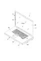
図1ないし図3は、電子機器としてのポータブルコンピュータ1を開示している。ポータブルコンピュータ1は、本体ユニット2と表示ユニット3とを備えている。本体ユニット2は、偏平な箱状をなす第1の筐体4を有している。第1の筐体4は、上壁4a、底壁4b、前壁4c、左右の側壁4dおよび後壁4eを備えている。上壁4aは、キーボード5を支持している。
1 to 3 disclose a
第1の筐体4の少なくとも底壁4bは、例えばマグネシウム合金のような金属材料で作られている。この底壁4bは、膨出部6と凹部7とを有している。膨出部6は、底壁4bの後半部に位置するとともに、底壁4bの前半部よりも下向きに突出している。凹部7は、膨出部6の直前において第1の筐体4の内側に向けて凹んでいる。この凹部7は、第1の筐体4の幅方向に沿う中央部に位置している。
At least the
膨出部6の底に一対の第1の脚部8a,8bが形成されている。同様に底壁4bの前端部に一対の第2の脚部9a,9bが形成されている。第1および第2の脚部8a,8b,9a,9bは、第1の筐体4の幅方向に互いに離れている。
A pair of
図2に示すように、ポータブルコンピュータ1を例えば机の天板11の上に置いた状態では、第1および第2の脚部8a,8b,9a,9bが天板11の上面に接触する。この結果、第1の筐体4は、前下がりの姿勢に傾斜するとともに、膨出部6の底と天板11の上面との間および底壁4bと天板11の上面との間に隙間12が形成されるようになっている。
As shown in FIG. 2, when the
図2および図3に示すように、第1の筐体4の後壁4eは、複数の第1の排気口13を有している。第1の排気口13は、第1の筐体4の幅方向に一列に並んでいる。膨出部6は、凹部7との間に介在される仕切り壁14を有している。この仕切り壁14に複数の第2の排気口15が形成されている。第2の排気口15は、第1の筐体4の幅方向に一列に並んでいるとともに、凹部7に開口している。
As shown in FIGS. 2 and 3, the
表示ユニット3は、第2の筐体17と液晶表示パネル18とを備えている。液晶表示パネル18は、第2の筐体17に収容されている。液晶表示パネル18は、画像を表示するスクリーン18aを有している。スクリーン18aは、第2の筐体17の前面に形成した開口部19を通じて第2の筐体17の外方に露出している。
The
第2の筐体17は、第1の筐体4の後端部に図示しないヒンジを介して支持されている。このため、表示ユニット3はキーボード5を上方から覆うように本体ユニット2の上に横たわる閉じ位置と、キーボード5やスクリーン18aを露出させるように本体ユニット2に対し起立する開き位置との間で回動可能となっている。
The
図2および図4に示すように、第1の筐体4はプリント回路板20を収容している。プリント回路板20の後端部の上面に発熱源としてのCPU21が実装されている。CPU21は、ベース基板22と、ベース基板22の上面の中央部に位置するICチップ23とを有している(図5参照)。ICチップ23は、処理速度の高速化や多機能化に伴って動作中の発熱量が非常に大きく、安定した動作を維持するために冷却を必要としている。
As shown in FIGS. 2 and 4, the
図4に示すように、第1の筐体4は、例えば不凍液のような液状冷媒を用いてCPU21を冷却する液冷式の冷却装置24を収容している。冷却装置24は、ポンプユニット25、放熱部としての放熱器26および循環経路27を備えている。
As shown in FIG. 4, the
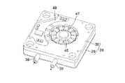
図4ないし図7に示すように、ポンプユニット25は、受熱部を兼ねるポンプハウジング28を有している。ポンプハウジング28は、ハウジング本体29とトップカバー30とで構成されている。ハウジング本体29は、CPU21よりも一回り大きな偏平な箱形であり、例えばアルミニウム合金のような熱伝導性に優れた金属材料で作られている。
As shown in FIGS. 4 to 7, the
ハウジング本体29は、上向きに開放された凹部31を有している。凹部31の底壁32は、CPU21と向かい合っている。底壁32の下面は、平坦な受熱面33となっている。トップカバー30は、合成樹脂製であり、凹部31の開口端を液密に閉塞している。
The
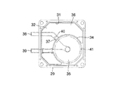
ポンプハウジング28の内部は、リング状の隔壁34によってポンプ室35とリザーブタンク36とに仕切られている。リザーブタンク36は、液状冷媒を蓄えるためのものであり、ポンプ室35を取り囲んでいる。隔壁34は、ハウジング本体29の底壁32から起立しており、この隔壁34にポンプ室35とリザーブタンク36とを連通させる連通口37が形成されている。
The inside of the
ハウジング本体29に吸込管38と吐出管39が一体に形成されている。吸込管38および吐出管39は、互いに間隔を存して水平に配置されている。吸込管38の上流端は、ハウジング本体29の側面から外方に突出している。吸込管38の下流端は、リザーブタンク36の内部に開口するとともに、隔壁34の連通口37と向かい合っている。図8に示すように、吸込管38の下流端と連通口37との間に気液分離用の隙間40が形成されている。隙間40は、ポンプハウジング28の姿勢が変化した場合でも、常にリザーブタンク36に蓄えられた液状冷媒の液面下に位置するようになっている。
A
吐出管39の下流端は、ハウジング本体29の側面から外方に突出するとともに、吸込管38の上流端と並んでいる。吐出管39の上流端は、隔壁34を貫通してポンプ室35に開口している。
The downstream end of the
ポンプハウジング28のポンプ室35に円盤状の羽根車41が収容されている。羽根車41は、その回転中心部に回転軸42を有している。回転軸42は、ハウジング本体29の底壁32とトップカバー30との間に跨るとともに、これら底壁32およびトップカバー30に回転自在に支持されている。
A disc-shaped
ポンプハウジング28に羽根車41を回転させるモータ43が組み込まれている。モータ43は、ロータ44およびステータ45を備えている。ロータ44は、リング状をなしている。ロータ44は、羽根車41の上面に同軸状に固定されているとともに、ポンプ室35に収容されている。ロータ44の内側に複数の正極と複数の負極が交互に着磁されたマグネット46が嵌め込まれている。マグネット46は、ロータ44および羽根車41と一体に回転するようになっている。
A
ステータ45は、トップカバー30の上面に形成した凹所47に収容されている。凹所47は、ロータ44の内側に入り込んでいる。このため、ステータ45は、ロータ44の内側に同軸状に収容されている。トップカバー30の上面にモータ43を制御する制御基板48が支持されている。制御基板48はステータ45に電気的に接続されている。
The
ステータ45に対する通電は、例えばポータブルコンピュータ1の電源投入と同時に行われる。この通電により、ステータ45の周方向に回転磁界が発生し、この磁界とロータ44のマグネット46とが磁気的に結合する。この結果、ステータ45とマグネット46との間にロータ44の周方向に沿うトルクが発生し、羽根車41が図6に矢印で示す時計回り方向に回転する。
Energization of the
トップカバー30の上面に複数のねじ50を介してバックプレート51が固定されている。バックプレート51は、ステータ45および制御基板48を覆い隠している。
A
このような構成のポンプユニット25は、CPU21を上方から覆うようにプリント回路板20の上に置かれている。図5に示すように、ポンプユニット25のポンプハウジング28は、プリント回路板20と共に第1の筐体4の底壁4bに固定されている。底壁4bは、ポンプハウジング28の四つの角部に対応する位置にボス部52を有している。ボス部52は、底壁4bから上向きに突出しており、これらボス部52の先端面にプリント回路板20が重ねられている。
The
ポンプハウジング28の四つの角部に上方からねじ53が挿通されている。ねじ53は、トップカバー30、ハウジング本体29およびプリント回路板20を貫通してボス部52にねじ込まれている。このねじ込みにより、ポンプユニット25およびプリント回路板20が底壁4bに固定されるとともに、ハウジング本体29の受熱面33がCPU21のICチップ23に熱的に接続される。
図2に示すように、冷却装置24の放熱器26は、第1の筐体4の膨出部6に収容されている。放熱器26は、ファン54と放熱体55とを備えている。ファン54は、偏平なケース56と、このケース56に収容された遠心式の羽根車57とを有している。ケース56は、ケース本体58とトッププレート59とで構成されている。ケース本体58は、第1の筐体4の底壁4bと一体化されている。
As shown in FIG. 2, the
言換えると、膨出部6は、その底から立ち上がる周壁60を有している。図9に示すように、周壁60は、円弧状に湾曲する第1の部分60aと、第1の部分60aの一端から直線状に延びる第2の部分60bと、上記第1の部分60aの他端から直線状に延びる第3の部分60cとを有している。第2の部分60bと第3の部分60cとは、互いに間隔を存して平行に配置されている。トッププレート59は、周壁60の上端部に固定されて膨出部6の底と向い合っている。
In other words, the bulging
ケース56は、一対の吸込口62a,62bと、一対の吐出口63a,63bとを有している。一方の吸込口62aは、トッププレート59の中央部に開口している。他方の吸込口62bは、膨出部6の底に開口するとともに一方の吸込口62aと向かい合っている。この他方の吸込口62bは、異物の吸い込みを防止するメッシュ状のガード64で覆われている。さらに、他方の吸込口62bの内側に円盤状のモータ支持部65が形成されている。
The
吐出口63a,63bは、ケース本体58の周壁60に形成されている。一方の吐出口63aは、第2の部分60bの先端縁、第3の部分60cの先端縁およびトッププレート59の縁で囲まれる領域で定められている。一方の吐出口63aは、第1の筐体4の幅方向に延びる細長い開口形状を有するとともに、後壁4eの第1の排気口13に向けて開口している。他方の吐出口63bは、周壁60の第1の部分60aに形成されており、一方の吐出口63aに対しケース56の中心点C1を間に挟んだ反対側に位置している。他方の吐出口63bは、仕切り壁14の第2の排気口15に向けて開口している。
The
羽根車57は、円筒状のボス部66と、このボス部66の外周面から放射状に突出する複数の羽根67とを有している。羽根車57は、そのボス部66に組み込まれた偏平モータ68を介してケース本体58のモータ支持部65に支持されている。このため、羽根車57は、吸込口62a,62bの間に位置している。
The
モータ68は、羽根車57を図9に矢印で示す反時計回り方向に回転させる。この回転により、吸込口62a,62bに負圧が作用し、ケース56の外部の空気が吸込口62a,62bを介して羽根車57の回転中心部に吸い込まれる。吸い込まれた空気は、遠心力によって羽根車57の外周部から放射状に吐き出される。
The
羽根車57は、回転中心R1を有している。羽根車57の回転中心R1は、ケース56の中心C1に対し周壁60の第2の部分60bに近づく方向に距離Lだけ偏心した領域に位置している。
The
この羽根車57の偏心により、羽根車57の外周部とケース56の周壁60との間に形成される隙間Gが羽根車57の回転方向に沿って次第に増加している。したがって、隙間Gは、ケース56の内部に羽根車57を取り囲む渦巻き室71を構成している。渦巻き室71は、羽根車57の外周から吐き出される空気を集めて吐出口63a,63bの方向に送るためのものであり、この空気の速度エネルギを圧力エネルギに変換する機能を有している。
Due to the eccentricity of the
図9に示すように、渦巻き室71の渦巻きの形状は、主に周壁60の第1の部分60aによって規定されている。渦巻き室71は、巻き始めの位置P1と巻き終わりの位置P2とを有している。巻き始めの位置P1は、周壁60の第2の部分60bに位置するとともに、一方の吐出口63aの一端に隣接している。巻き終わりの位置P2は、巻き始めの位置P1から羽根車57の回転方向に所定の角度ずれた位置にある。羽根車57の外周部と周壁60との間の隙間Gは、巻き始めの位置P1において最も小さいとともに、この巻き始めの位置P1から巻き終わりの位置P2の方向に進むに従い逐次増大している。
As shown in FIG. 9, the spiral shape of the
放熱器26の放熱体55は、ケース56の周壁60と羽根車57との間に配置されているとともに、渦巻き室71に露出している。図9ないし図13に示すように、放熱体55は、液状冷媒が流れる冷媒通路73と複数の放熱フィン74とを備えている。冷媒通路73は、例えば偏平な銅パイプで構成されており、長軸L1と短軸L2とを有している。冷媒通路73は、羽根車57を同軸状に取り囲むようなリング状をなしている。この冷媒通路73は、短軸L2を第1の筐体4の厚み方向に沿わせた姿勢で膨出部6の底の上に重ね合わされている。このため、冷媒通路73は、第1の筐体4に熱的に接続されている。
The
冷媒通路73は、上流端73aと下流端73bとを有している。上流端73aおよび下流端73bは、互いに平行となるように羽根車57の径方向外側に向けて引き出されている。冷媒通路73の上流端73aでは、その断面形状が円形に変化している。この上流端73aは、液状冷媒が流れ込む冷媒入口76となっている。同様に冷媒通路73の下流端73bでは、その断面形状が円形に変化している。この下流端73bは、液状冷媒が流出する冷媒出口77となっている。
The
冷媒通路73の冷媒入口76および冷媒出口77は、羽根車57の回転中心R1が位置するケース56の領域からケース56の外に導かれている。詳しく述べると、冷媒入口76を有する冷媒通路73の上流端73aおよび冷媒出口77を有する冷媒通路73の下流端73bは、渦巻き室71の巻き始めの位置P1と他方の吐出口63bとの間に位置するとともに、ここから周壁60の第1の部分60aを貫通してケース56の外に導かれている。このため、冷媒入口76および冷媒出口77は、渦巻き室71のうち周壁60と羽根車57の外周との間の隙間Gが小さい巻き始めの位置P1の近傍からケース56の外に突出している。
The
各放熱フィン74は、例えばアルミニウム合金のような熱伝導性に優れた金属材料で作られており、四角い板状をなしている。放熱フィン74は、羽根車57の周方向に互いに間隔を存して並んでいるとともに、羽根車57に対し放射状に配置されている。
Each radiating
放熱フィン74は、第1の筐体4の厚み方向に沿って起立している。放熱フィン74の下端は、偏平な冷媒通路73の上面に例えば半田付け等の手段により固定されている。これにより、放熱フィン74の配置間隔が定まるとともに、放熱フィン74が冷媒通路73に熱的に接続されている。放熱フィン74の上端は、ケース56のトッププレート59の内面に突き当たり、このトッププレート59に熱的に接続されている。
The
上記冷却装置24の循環経路27は、第1の管路80と第2の管路81とを有している。第1の管路80は、ポンプハウジング28の吐出管39と冷媒通路73の冷媒入口76との間を接続している。第2の管路81は、ポンプハウジング28の吸込管38と冷媒通路73の冷媒出口77との間を接続している。
The
言換えると、放熱体55の冷媒通路73は、第1の管路80と第2の管路81との間を接続する第3の管路として機能している。この結果、液状冷媒は、第1の管路80、第2の管路81および冷媒通路73を通じてポンプユニット25と放熱器26との間で循環するようになっている。
In other words, the
図4に示すように、冷媒通路73は、第1ないし第3の放熱領域82a〜82cを有している。第1の放熱領域82aは、第1の管路80を通じて高温の液状冷媒が最初に流れ込む部位であり、冷媒通路73の上流端73aを含んでいる。そのため、第1の放熱領域82aは、冷媒通路73の中で最も温度が高くなっている。この第1の放熱領域82aは、周壁60の第2の部分60bから一方の吐出口63aに向けて延びているとともに、この吐出口63aと向かい合っている。
As shown in FIG. 4, the
冷媒通路73の第2の放熱領域82bは、第1の放熱領域82aの下流に位置している。この第2の放熱領域82bは、周壁60の第3の部分60cと向かい合うとともに、渦巻き室71の中でも羽根車57と周壁60との間の隙間Gが最も広がった箇所に位置している。
The second
冷媒通路73の第3の放熱領域82cは、第2の放熱領域82bの下流に位置している。この第3の放熱領域82cは、冷媒通路73の下流端73bを含んでおり、冷媒通路73の中で最も温度が低くなっている。この第3の放熱領域82cは、周壁60の第1の部分60aに沿うとともに他方の吐出口63bと向かい合っている。
The third
次に、冷却装置24の動作について説明する。
Next, the operation of the
ポータブルコンピュータ1の使用中、CPU21のICチップ23が発熱する。ICチップ23が発する熱は、受熱面33を通じてポンプハウジング28に伝わる。ポンプハウジング28のポンプ室35およびリザーブタンク36は、液状冷媒で満たされているので、この液状冷媒がポンプハウジング28に伝わった熱の多くを吸収する。
During use of the
モータ43のステータ45に対する通電は、ポータブルコンピュータ1の電源投入と同時に行われる。これにより、ステータ45とロータ44のマグネット46との間にトルクが発生し、ロータ44が羽根車41を伴って回転する。羽根車41が回転すると、ポンプ室35内の液状冷媒が加圧されて吐出管39から吐き出されるとともに、第1の管路80を通じて放熱器26に導かれる。
Energization of the
詳しく述べると、ポンプハウジング28での熱交換により加熱された液状冷媒は、冷媒入口76から冷媒通路73に送り込まれる。この液状冷媒は、冷媒通路73を冷媒出口77に向けて流れる。この流れの過程で液状冷媒に吸収されたICチップ23の熱が冷媒通路73に伝わるとともに、この冷媒通路73から放熱フィン74に伝わる。
More specifically, the liquid refrigerant heated by heat exchange in the
本実施の形態によると、冷媒通路73は、第1の筐体4の膨出部6に熱的に接続されているので、液状冷媒から冷媒通路73に伝えられた熱を第1の筐体4に拡散させることができる。それとともに、放熱フィン74にしてもケース56のトッププレート59に熱的に接続されているので、液状冷媒から放熱フィン74に伝えられた熱をトッププレート59に逃がすことができる。このため、第1の筐体4やトッププレート59の表面を放熱面として利用することができ、放熱器26の放熱性能が高まる。
According to the present embodiment, since the
ポータブルコンピュータ1に使用中に放熱器26の羽根車57が回転すると、この羽根車57の外周部から放射状に空気が吐き出される。この空気は、冷却風となって隣り合う放熱フィン74の間を通り抜ける。これにより、冷媒通路73や放熱フィン74が冷やされ、これら両者に伝えられた熱の多くが冷却風の流れに乗じて持ち去られる。
When the
放熱フィン74を通り抜けた冷却風は、ケース56の内部の渦巻き室71に導かれる。渦巻き室71は、冷却風の速度エネルギを圧力エネルギに変換するので、渦巻き室71の圧力が巻き始めの位置P1から巻き終わりの位置P2に進むに従い次第に高くなる。この結果、ケース56の吐出口63a,63bから吐き出される冷却風の風量が増大し、放熱体55を冷却した冷却風をケース56の外に効率良く排出できる。
The cooling air that has passed through the
ケース56の吐出口63a,63bは、第1の筐体4の第1および第2の排気口13,15と向かい合うように互いに異なる二方向に向けて開口している。このため、図2に矢印で示すように、一方の吐出口63aから吐き出される冷却風は、第1の排気口13を通じて第1の筐体4の後方に排出される。他方の吐出口63bから吐き出される冷却風は、第2の排気口15を通じて第1の筐体4の底壁4bの方向に排出される。
The
この際、第2の排気口15は、底壁4bの凹部7に開口するとともに、ポータブルコンピュータ1を机の天板11の上に置いた状態では、底壁4bと天板11との間に凹部7に連なる隙間12が形成されている。よって、第2の排気口15から排出される冷却風は、凹部7から隙間12を介して第1の筐体4の外に流出し、この冷却風の流れが天板11によって阻害されることはない。
At this time, the
一方、放熱器26での熱交換により冷やされた液状冷媒は、冷媒出口77から第2の管路81を介してポンプハウジング28の吸込管38に導かれる。この液状冷媒は、吸込管38の下流端から隙間40を通ってリザーブタンク36の内部に吐き出される。これにより、冷媒通路73を流れる液状冷媒中に気泡が含まれていた場合に、この気泡がリザーブタンク36の内部で液状冷媒中から分離除去される。
On the other hand, the liquid refrigerant cooled by heat exchange in the
リザーブタンク36に戻された液状冷媒は、連通口37からポンプ室35に吸い込まれる。ポンプ室35に吸い込まれた液状冷媒は、再び加圧されて吐出管39から放熱器26に送り込まれる。
The liquid refrigerant returned to the
このようなサイクルを繰り返すことで、ICチップ23の熱が放熱器26の放熱体55に順次移送され、この放熱体55の放熱フィン74の間を通過する冷却風の流れに乗じてポータブルコンピュータ1の外部に放出される。
By repeating such a cycle, the heat of the IC chip 23 is sequentially transferred to the
ところで、上記構成の放熱器26によると、加熱された液状冷媒が流れる冷媒通路73は、ファン54の羽根車57を略全周に亘って取り囲んでいるとともに、羽根車57に対し放射状に配置された複数の放熱フィン74に熱的に接続されている。このため、羽根車57の全周から放射状に吐き出す冷却風を利用して冷媒通路73や放熱フィン74を効率良く冷やすことができる。
By the way, according to the
よって、放熱体55は、羽根車57の周方向に沿う広い範囲から液状冷媒に吸収されたICチップ23の熱を放出することができる。
Therefore, the
しかも、羽根車57および放熱体55は、吐出口63a,63bを有する専用のケース56に収容されている。そのため、羽根車57の外周部から吐き出された冷却風は、放熱体55の放熱フィン74の間を通り抜けた後、ケース56の吐出口63a,63bから第1の筐体4の第1および第2の排気口13,15を通じてポータブルコンピュータ1の外部に排出される。この結果、放熱器26での熱交換により加熱された冷却風の吐き出し方向をケース56によって規定することができる。したがって、高温の冷却風を放熱器26の周囲に拡散させることなく第1の筐体4の外部に効率良く排出できる。
Moreover, the
特に本実施の形態では、羽根車57の回転中心R1をケース56の中心C1に対し偏心させることで、ケース56の内部に渦巻き室71を形成している。渦巻き室71は、冷却風の速度エネルギを圧力エネルギに変換するので、放熱体55を冷却した冷却風をケース56の吐出口63a,63bからケース56の外に効率良く排出できる。
In particular, in the present embodiment, the
加えて、放熱器26の冷媒通路73は、ポンプハウジング28での熱交換により加熱された液状冷媒が最初に流れ込む第1の放熱領域82aを有し、この第1の放熱領域82aがケース56の吐出口63aと向かい合っている。このため、加熱された液状冷媒は、冷媒通路73に導かれた時点で吐出口63aに近づく方向に流れる。この結果、冷媒通路73の中で最も高温の第1の放熱領域82aを冷却した冷却風は、ケース56の内部を流れることなく、そのまま吐出口63aから第1の排気口13を通じて第1の筐体4の外部に排出される。
In addition, the
したがって、ケース56に対する冷媒通路73の熱影響を極力少なく抑えることができ、放熱器26の放熱性能を高める上で好都合となる。
Accordingly, the heat influence of the
さらに、上記構成の放熱器26によると、ファン54のケース56の内部に羽根車57を取り囲むように放熱体55が収容されている。このため、羽根車57および放熱体55がケース56を介して一つのユニットとして組み立てられており、これら両者の位置関係が精度良く定まる。よって、羽根車57の外周部から放射状に吐き出される冷却風を万遍なく放熱体55に導くことができ、放熱器26の放熱性能の向上に寄与する。
Further, according to the
それとともに、上記放熱器26によれば、冷媒通路73の冷媒入口76および冷媒出口77は、渦巻き室71の中でもケース56の周壁60と羽根車57の外周部との間の隙間Gが小さい巻き始めの位置P1の近傍を通してケース56の外に引き出されている。よって、渦巻き室71のうち冷却風の圧力が高まる部分を冷媒入口76および冷媒出口77が横切ることはなく、冷却風の通風抵抗を小さく抑えて効率の良い排気が可能となる。
In addition, according to the
本発明は上記第1の実施の形態に特定されるものではない。図14は、本発明の第2の実施の形態を開示している。 The present invention is not limited to the first embodiment. FIG. 14 discloses a second embodiment of the present invention.
この第2の実施の形態では、ケース本体58を構成する膨出部6の底に凹部91が形成されている。凹部91は、冷媒通路73に沿うように円弧状に形成されている。冷媒通路73は、凹部91に嵌め込んだ状態で膨出部6の底に半田付けされている。
In the second embodiment, a
この構成によれば、ケース本体58に対する冷媒通路73の位置が精度良く定まり、放熱器26の組み立て時の作業性が向上する。それとともに、膨出部6の底と冷媒通路73との接触面積が増大する。このため、冷媒通路73に伝えられた液状冷媒の熱を膨出部6を通じて第1の筐体4に効率良く逃がすことができる。
According to this configuration, the position of the
図15は、本発明の第3の実施の形態を開示している。 FIG. 15 discloses a third embodiment of the present invention.
この第3の実施の形態は、CPU21の熱を吸収する受熱部100と、液状冷媒を加圧して送り出すポンプ101とを分離した点が上記第1の実施の形態と相違している。これ以外の冷却装置24の構成は、第1の実施の形態と同様である。そのため、第2の実施の形態において第1の実施の形態と同一の構成部分には、同一の参照符号を付してその説明を省略する。
The third embodiment is different from the first embodiment in that the
図15に示すように、受熱部100はハウジング102を備えている。ハウジング102は、CPU21よりも一回り大きな偏平な四角い箱形であり、その内部に液状冷媒が流れる受熱室(図示せず)を有している。ハウジング102に冷媒入口103および冷媒出口104が形成されている。冷媒入口103および冷媒出口104は、受熱室に開口するとともにハウシング102の側面から互いに平行に突出している。
As shown in FIG. 15, the
ハウジング102は、CPU21を上方から覆うようにプリント回路板20の上に置かれている。ハウジング102は、その四つの角部がねじ105を介してプリント回路板20に固定されている。この固定により、ハウジング102がCPU21に熱的に接続され、このハウジング102内を流れる液状冷媒がCPU21の熱を吸収する。
The
循環経路27の第1の管路80は、受熱部100の冷媒出口104と放熱体55の冷媒入口76との間を接続している。循環経路27の第2の管路81は、受熱部100の冷媒入口103と放熱体55の冷媒出口77との間を接続している。ポンプ101は、第2の管路81の途中に設置されている。このため、液状冷媒は、第1および第2の管路80,81を通じて受熱部100と放熱器26との間で循環するようになっている。
The
このような構成においても、受熱部100での熱交換により加熱された液状冷媒を放熱器26の冷媒通路73に導くことができる。そのため、上記第1の実施の形態と同様の効果が得られる。
Even in such a configuration, the liquid refrigerant heated by heat exchange in the
なお、第3の実施の形態では、ポンプ101を第2の管路81に設置したが、本発明はこれに制約されない。例えば受熱部100で加熱された液状冷媒を放熱器26に導く第1の管路80にポンプ101を設置してもよい。
In the third embodiment, the
図16は、本発明の第4の実施の形態を開示している。 FIG. 16 discloses a fourth embodiment of the present invention.
この第4の実施の形態は、放熱器26からの冷却風の排出方向に関する事項が上記第1の実施の形態と相違している。これ以外の冷却装置24の構成は第1の実施の形態と同様である。このため、第4の実施の形態において、第1の実施の形態と同一の構成部分は同一の参照符号を付して、その説明を省略する。
The fourth embodiment is different from the first embodiment in matters relating to the discharge direction of the cooling air from the
図16に示すように、第1の筐体4は、左側の側壁4dと後壁4eとで規定されるコーナ部120を備えている。側壁4dは、コーナ部120に対応する位置に複数の第1の排気口121を有している。第1の排気口121は、第1の筐体4の奥行き方向に間隔を存して並んでいる。後壁4eは、コーナ部120に対応する位置に複数の第2の排気口122を有している。第2の排気口122は、第1の筐体4の幅方向に間隔を存して並んでいる。
As shown in FIG. 16, the
プリント回路板20に実装されたCPU21は、コーナ部120の前方にずれた位置にあり、このCPU21にポンプユニット25が熱的に接続されている。ポンプハウジング28の吸込管38および吐出管39は、コーナ部120に向けて突出している。
The
放熱器26は、第1の筐体4のコーナ部120に位置している。放熱器26のケース本体58は、一対の吐出口123a,123bを有している。吐出口123a,123bは、ケース本体58の周壁60に形成されている。
The
一方の吐出口123aは、第2の部分60bの先端縁と第3の部分60cの先端縁との間に位置している。一方の吐出口123aは、第1の筐体4の奥行き方向に延びる細長い開口形状を有するとともに、側壁4dの第1の排気口121に向けて開口している。他方の吐出口123bは、周壁60の第3の部分60cに形成され、第1の筐体4の幅方向に延びる細長い開口形状を有している。他方の吐出口123bは、一方の吐出口123aと隣り合うとともに、この吐出口123aに対し直交し合うような位置関係を保っている。他方の吐出口123bは、後壁4eの第2の排気口122に向けて開口している。
One
冷媒通路73の第1の放熱領域82aは、周壁60の第2の部分60bから一方の吐出口123aに向けて延びているとともに、この吐出口123aと向かい合っている。冷媒通路73の第2の放熱領域82bは、渦巻き室71の中でも羽根車57と周壁60との間の隙間Gが最も広がった箇所に位置するとともに、他の吐出口123bと向かい合っている。冷媒通路73の第3の放熱領域82cは、周壁60の第1の部分60aと向かい合っている。
The first
このような構成において、放熱器26の羽根車57が回転すると、この羽根車57の外周部から放射状に空気が吐き出される。この空気は、冷却風となって隣り合う放熱フィン74の間を通り抜け、これにより、放熱体55を冷却する。
In such a configuration, when the
羽根車57および放熱体55を収容するケース56は、隣り合う二つの吐出口123a,123bを有している。これら吐出口123a,123bは、第1の筐体4の第1および第2の排気口121,122と向かい合うように互いに直交する方向に開口している。そのため、一方の吐出口123aから吐き出される冷却風は、第1の排気口121を通じて第1の筐体4の左側方に排出される。他方の吐出口123bから吐き出される冷却風は、第2の排気口122を通じて第1の筐体4の後方に排出される。
The
放熱器26の冷媒通路73のうち、加熱された液状冷媒が最初に流れ込む第1の放熱領域82aは、ケース56の一方の吐出口123aと向かい合っている。さらに、第1の放熱領域82aの下流に位置する第2の放熱領域82bは、ケース56の他方の吐出口123bと向かい合っている。
Of the
このため、加熱された液状冷媒は、冷媒通路73に導かれた時点で吐出口123a,123bに近づく方向に流れる。この結果、冷媒通路73の中でも温度が高い第1および第2の放熱領域82a,82bを冷却した冷却風は、ケース56の内部を流れることなく、そのまま吐出口123a,123bから第1および第2の排気口121,122を通じて第1の筐体4の外部に排出される。
For this reason, the heated liquid refrigerant flows in a direction approaching the
したがって、ケース56に対する冷媒通路73の熱影響を極力少なく抑えることができ、放熱器26の放熱性能を高める上で好都合となる。
Accordingly, the heat influence of the
図17は、本発明の第5の実施の形態を開示している。 FIG. 17 discloses a fifth embodiment of the present invention.
この第5の実施の形態は、CPU21の位置および冷却装置24の向きが上記第4の実施の形態と相違している。これ以外の構成は第4の実施の形態と同様であるので、第4の実施の形態と同一の構成部分には同一の参照符号を付して、その説明を省略する。
In the fifth embodiment, the position of the
図17に示すように、プリント配線板20に実装されたCPU21は、コーナ部120の右側にずれた位置にあり、このCPU21にポンプユニット25のポンプハウジング28が熱的に接続されている。ポンプハウジング28の吸込管38および吐出管39は、コーナ部120に向けて突出している。
As shown in FIG. 17, the
放熱器26は、第1の筐体4のコーナ部120に位置している。放熱器26の一方の吐出口123aは、第1の筐体4の幅方向に延びる細長い開口形状を有するとともに、後壁4eの第2の排気口122に向けて開口している。他方の吐出口123bは、第1の筐体4の奥行き方向に延びる細長い開口形状を有するとともに、側壁4dの第1の排気口123aに向けて開口している。
The
このような構成によると、放熱器26の一方の吐出口123aから吐き出される冷却風は、第2の排気口122を通じて第1の筐体4の後方に排出される。他方の吐出口123bから吐き出される冷却風は、第1の排気口121を通じて第1の筐体4の左側方に排出される。
According to such a configuration, the cooling air discharged from one
放熱器26の冷媒通路73のうち、加熱された液状冷媒が最初に流れ込む第1の放熱領域82aは、ケース56の一方の吐出口123aと向かい合っている。さらに、第1の放熱領域82aの下流に位置する第2の放熱領域82bは、ケース56の他方の吐出口123bと向かい合っている。
Of the
このため、加熱された液状冷媒は、冷媒通路73に導かれた時点で吐出口123a,123bに近づく方向に流れる。この結果、冷媒通路73の中でも温度が高い第1および第2の放熱領域82a,82bを冷却した冷却風は、ケース56の内部を流れることなく、そのまま吐出口123a,123bから第1および第2の排気口121,122を通じて第1の筐体4の外部に排出される。よって、上記第4の実施の形態と同様に、ケース56に対する冷媒通路73の熱影響を極力少なく抑えることができる。
For this reason, the heated liquid refrigerant flows in a direction approaching the
図18は、本発明の第6の実施の形態を開示している。 FIG. 18 discloses a sixth embodiment of the present invention.
この第6の実施の形態は、放熱器26のケース本体130を第1の筐体4とは別の部品で構成したものである。これ以外の放熱器26の構成は、第1の実施の形態と同様であるので、第1の実施の形態と同一の構成部分には同一の参照符号を付して、その説明を省略する。
In the sixth embodiment, the case
放熱器26のケース本体130は、例えばアルミニウム合金のような熱伝導性に優れた金属材料で構成されている。図18に示すように、ケース本体130は、底板131と、この底板131の外周縁から立ち上がる側板132とを備えている。
The case
底板131は、吸込口133と、この吸込口133の内側に位置するモータ支持部134とを有している。羽根車57は、モータ68を介してモータ支持部134に支持されている。羽根車57は、吸込口62a,133の間に位置している。底板131は、膨出部6の内面に例えば複数のねじを介して固定されている。底板131の吸込口133は、膨出部6の底に開けた開口部135に連なっている。開口部135は、ガード64によって覆われている。
The
ケース本体130の側板132は、羽根車57を取り囲んでいる。側板132は、羽根車57を間に挟んで向かい合う吐出口63a,63bを有している。
The
液状冷媒が流れる冷媒通路73は、底板131の上に重ね合わされている。このため、冷媒通路73は、ケース本体130に熱的に接続されている。
The
図19および図20は、本発明の第7の実施の形態を開示している。 19 and 20 disclose a seventh embodiment of the present invention.
この第7の実施の形態は、主に放熱体55の冷媒通路140の形状が上記第1の実施の形態と相違している。
The seventh embodiment is mainly different from the first embodiment in the shape of the
図19に示すように、冷媒通路140は、第1ないし第3の通路141,142,143を有している。第1の通路141は、放熱体55の一端から他端に向けて延びている。第2の通路142は、放熱体55の他端から一端に向けて延びている。第3の通路143は、第1の通路141の下流端と第2の通路142の上流端との間を結んでいる。
As shown in FIG. 19, the
第1および第2の通路141,142は、羽根車57を取り囲むように円弧状に湾曲している。さらに、第1の通路141は、第2の通路142の外側に位置している。
The first and
第1の通路141の上流端と第2の通路142の下流端は、互いに並んだ状態で放熱体55の一端から引き出されている。第3の通路143は、放熱体55の一端と他端との間に位置している。第1の通路141の上流端は、第1の管路80を介してポンプユニット25の吐出管39に接続されている。第2の通路142の下流端は、第2の管路81を介してポンプユニット25の吸込管38に接続されている。
The upstream end of the
第1ないし第3の通路141,142,143は、夫々偏平なパイプ144で構成されている。図20に示すように、パイプ144は、長軸L1および短軸S1を有している。長軸L1は、放熱フィン74の長さ方向に沿って延びている。短軸S1は、放熱フィン74の高さ方向に沿って延びている。
The first to
放熱フィン74の下端に第1および第2の凹部145a,145bが形成されている。第1および第2の凹部145a,145bは、放熱フィン74の長さ方向に間隔を存して並んでいる。第1の通路141は、第1の凹部145aに嵌まり込むとともに、放熱フィン74の下端に半田付けされている。第2の通路142は、第2の凹部145bに嵌まり込むとともに、放熱フィン74の下端に半田付けされている。したがって、第1および第2の通路141,142は、夫々放熱フィン74に熱的に接続されている。
First and
さらに、放熱フィン74の上端に円弧状に湾曲する連結板146が半田付けされている。複数の放熱フィン74は、第1の通路141、第2の通路142および連結板146を介して連結されており、これにより隣り合う放熱フィン74の配置間隔が一定に保たれている。
Further, a connecting
このような構成によると、ポンプハウジング28での熱交換により加熱された液状冷媒は、先ず最初に冷媒通路140の第1の通路141に送り込まれる。この液状冷媒は、第1の通路141の下流端に達した後、第3の通路143を通じて第2の通路142に流れ込み、この第2の通路142の下流端に達する。この流れの過程で液状冷媒に吸収されたICチップ23の熱がパイプ144から放熱フィン74に伝わる。
According to such a configuration, the liquid refrigerant heated by heat exchange in the
言換えると、ポンプハウジング28から冷媒通路140に導かれた液状冷媒は、放熱体55の一端から他端に向けて流れた後、この他端から一端に向けて流れる。このため、冷媒通路140の長さが倍増し、一つの放熱フィン74に対し第1および第2の通路141,142の双方から熱が伝わることになる。
In other words, the liquid refrigerant guided from the
しかも、放熱フィン74の下端に第1および第2の通路141,142が嵌まり込む第1および第2の凹部145a,145bを形成したので、個々の放熱フィン74と第1および第2の通路141,142との接触面積が増大する。そのため、第1および第2の通路141,142を流れる液状冷媒の熱を効率良く放熱フィン74に移送することができる。
Moreover, since the first and
この結果、放熱フィン74の表面温度が上昇するとともに、放熱フィン74の隅々にまで熱が伝わり易くなる。よって、液状冷媒の熱を放熱フィン74の表面から効率良く放出することができ、放熱器26の放熱性能が高まる。
As a result, the surface temperature of the radiating
さらに、上記構成によると、加熱された液状冷媒が最初に流れ込む第1の通路141は、第2の通路142の外側に位置している。このため、図20に矢印で示すように、羽根車57の外周部から吐き出された冷却風は、第2の通路142と放熱フィン74との熱接続部を通過した後、第1の通路141と放熱フィン74との熱接続部を通過する。
Furthermore, according to the above configuration, the
第2の通路142を流れる液状冷媒は、第1の通路141を流れる過程で既に放熱フィン74との熱交換によりある程度冷却されている。これに対し、第1の通路141には、高温の液状冷媒が最初に導かれるので、第1の通路141と放熱フィン74との熱接続部の温度は、第2の通路142と放熱フィン74との熱接続部の温度よりも高くなる。
The liquid refrigerant flowing through the
上記構成の場合、第1の通路141と放熱フィン74との熱接続部は、第2の通路142と放熱フィン74との熱接続部よりも冷却風の流れ方向に沿う下流側に位置している。このため、第2の通路142と放熱フィン74との熱接続部に第1の通路141と放熱フィン74との熱接続部を通過した後の暖かい冷却風が導かれることはなく、第2の通路142が暖まった冷却風の熱影響を受けずに済む。
In the case of the above configuration, the thermal connection portion between the
したがって、放熱器26からポンプユニット25に戻る液状冷媒の温度上昇を防止することができる。
Therefore, the temperature rise of the liquid refrigerant returning from the
図21ないし図25は、本発明の第8の実施の形態を開示している。 21 to 25 disclose an eighth embodiment of the present invention.
この第8の実施の形態は、主に放熱体55の冷媒通路160の形状が上記第1の実施の形態と相違している
図21ないし図23に示すように、冷媒通路160は、液状冷媒が流れる第1ないし第3の通路161〜163を有している。第1ないし第3の通路161〜163は、連続した一本の偏平なパイプで構成されている。
In the eighth embodiment, the shape of the
第1の通路161は、羽根車57を取り囲むように円弧状に湾曲しており、隣り合う放熱フィン74の上端の間に跨っている。第1の通路161の上流端は、放熱体55の一端に位置するとともに、第1の通路161の下流端は、放熱体55の他端に位置している。第1の通路161の上流端は、第1の管路80を介してポンプユニット25の吐出管39に接続されている。図25に示すように、第1の通路161は、放熱フィン74の上端に形成した凹部165に嵌まり込むとともに、この放熱フィン74の上端に半田付けされている。
The
第2の通路162は、羽根車57を取り囲むように円弧状に湾曲しており、隣り合う放熱フィン74の下端の間に跨っている。第2の通路162の上流端は、放熱体55の一端に位置するとともに、第2の通路162の下流端は、放熱体55の他端に位置している。第2の通路162の下流端は、第2の管路81を介してポンプユニット25の吸込管38に接続されている。図25に示すように、第2の通路162は、放熱フィン74の下端に形成した凹部166に嵌まり込むとともに、この放熱フィン74の下端に半田付けされている。
The
第3の通路163は、放熱体55の一端と他端との間に配置されている。第3の通路163は、第1の通路161の下流端と第2の通路162の上流端との間を結ぶように放熱フィン74の高さ方向に斜めに延びている。
The
さらに、放熱フィン74の上端に円弧状に湾曲する一対の連結板167a,167bが半田付けされている。同様に、放熱フィン74の下端に円弧状に湾曲する一対の連結板168a,168bが半田付けされている。これにより、複数の放熱フィン74が第1の通路161、第2の通路162および連結板167a,167b,168a,168bによって連結されており、隣り合う放熱フィン74の配置間隔が一定に保たれている。
Further, a pair of connecting
このような構成によると、ポンプハウジング28で加熱された液状冷媒は、先ず最初に第1の通路161に導かれ、隣り合う放熱フィン74の上端を順次横断するように流れる。第1の通路161の下流端に達した液状冷媒は、第3の通路163を通じて第2の通路162に導かれ、隣り合う放熱フィン74の下端を順次横断するように流れる。この流れの過程で液状冷媒の熱が放熱フィン74に伝わる。
According to such a configuration, the liquid refrigerant heated by the
上記構成では、ポンプハウジング28から放熱器26に導かれた液状冷媒は、羽根車57を取り囲む第1および第2の通路141,142に沿って放熱体55を二周した後、ポンプハウジング28に戻される。このため、冷媒通路160の全長が倍増し、一つの放熱フィン74に対し第1および第2の通路161,162から液状冷媒の熱が伝わることになる。
In the above configuration, the liquid refrigerant guided from the
しかも、第1の通路161は、放熱フィン74の上端に形成した凹部165に嵌まり込むとともに、第2の通路162は、放熱フィン74の下端に形成した凹部166に嵌まり込んでいる。このため、放熱フィン74と第1および第2の通路161,162との接触面積が増大し、第1および第2の通路161,162を流れる液状冷媒の熱を効率良く放熱フィン74に移送することができる。
In addition, the
また、図23に示すように、第1の通路161が第2の通路162の上方に位置し、第3の通路163は、第1の通路161の下流端から第2の通路部162の上流端に向けて下向きに傾斜している。このため、第3の通路163の内部での液状冷媒の流れ方向が下向きとなる。この結果、液状冷媒を重力に抗して押し上げる必要はなく、液状冷媒が第1ないし第3の通路161〜163を通過する時の抵抗を少なく抑えることができる。
Further, as shown in FIG. 23, the
したがって、液状冷媒を加圧して吐き出すポンプユニット25の負担が軽減され、大きな駆動力を要することなく液状冷媒をポンプユニット25と放熱器26との間で循環させることができる。
Therefore, the load on the
なお、本発明は上記実施の形態に特定されるものではなく、発明の趣旨を逸脱しない範囲内で種々変形して実施可能である。 It should be noted that the present invention is not limited to the above-described embodiment, and can be implemented with various modifications without departing from the spirit of the invention.
例えば、上記実施の形態ではケースに二つの吐出口を設け、冷却風を互いに異なる方向に排出している。しかしながら、吐出口の数は上記実施の形態に限らず、一つでもよい。 For example, in the above embodiment, two discharge ports are provided in the case, and the cooling air is discharged in different directions. However, the number of discharge ports is not limited to the above embodiment, and may be one.
さらに、発熱源にしてもCPUに限らず、例えばチップセットであってもよい。それとともに、冷却装置を収容する筐体は金属製に限らず、合成樹脂製であっても同様に実施可能である。 Further, the heat generation source is not limited to the CPU, but may be a chip set, for example. At the same time, the housing for housing the cooling device is not limited to metal but can be implemented similarly even if it is made of synthetic resin.
4…筐体(第1の筐体)、13,15…排気口(第1および第2の排気口)、21…発熱源(CPU)、24…冷却装置、25…ポンプ(受熱部、ポンプユニット)、26…放熱器、27…循環経路、55…放熱体、56…ケース、57…羽根車、60…周壁、62a,62b…吸込口、63a,63b…吐出口、71…渦巻き室、73,140,160…冷媒通路(第3の管路)、74…放熱フィン、80…第1の管路、81…第2の管路、100…受熱部。
DESCRIPTION OF
Claims (12)
上記羽根車を取り囲むように配置され、発熱源との熱交換により加熱された液状冷媒が流れる冷媒通路と、上記冷媒通路に熱的に接続された複数の放熱フィンとを有する放熱体と、
上記羽根車および上記放熱体を収容するとともに、上記放熱体を冷却した冷却風を排出する少なくとも一つの吐出口を有するケースと、を具備し、
上記ケースは、上記羽根車の回転中心部に空気を導く吸込口と、上記放熱体を取り囲むとともに、この放熱体を通過した冷却風を集める渦巻き室とを有し、上記羽根車は、上記渦巻き室に対し偏心していることを特徴とする放熱器。 An impeller that exhales cooling air;
A heat dissipating body that is disposed so as to surround the impeller and has a refrigerant passage through which a liquid refrigerant heated by heat exchange with a heat generation source flows, and a plurality of heat dissipating fins thermally connected to the refrigerant passage;
Accommodates the impeller and the heat dissipation member, anda case having at least one discharge port for discharging the cooling air having cooled the heat radiator,
The case includes a suction port that guides air to a rotation center portion of the impeller, and a spiral chamber that surrounds the radiator and collects cooling air that has passed through the radiator, and the impeller includes the spiral A radiator characterized by being eccentric with respect to the chamber .
上記羽根車を収容するとともに、上記冷却風を排出する少なくとも一つの吐出口が形成された周壁と、上記羽根車の外周部と上記周壁との間に形成され、上記羽根車から吐き出される冷却風を集める渦巻き室とを有するケースと、
上記渦巻き室に配置され、上記羽根車を取り囲むとともに発熱源との熱交換により加熱された液状冷媒が流れる冷媒通路と、
上記冷媒通路に熱的に接続されて、上記渦巻き室に配置された複数の放熱フィンと、を具備したことを特徴とする放熱器。 An impeller that exhales cooling air;
Cooling air that is formed between the peripheral wall in which the impeller is housed and at least one discharge port for discharging the cooling air is formed, and the outer peripheral portion of the impeller and the peripheral wall, and is discharged from the impeller A case having a swirl chamber for collecting,
A refrigerant passage disposed in the spiral chamber, surrounding the impeller and flowing a liquid refrigerant heated by heat exchange with a heat source;
And a plurality of heat dissipating fins thermally connected to the refrigerant passage and disposed in the spiral chamber .
上記発熱源の熱を放出する放熱部と、A heat dissipating part for releasing the heat of the heat source;
上記受熱部と上記放熱部との間で液状冷媒を循環させる循環経路と、を具備し、A circulation path for circulating a liquid refrigerant between the heat receiving part and the heat radiating part,
上記放熱部は、The heat dissipation part
冷却風を吐き出す羽根車と、An impeller that exhales cooling air;
上記羽根車を取り囲むように配置され、発熱源との熱交換により加熱された液状冷媒が流れる冷媒通路と、上記冷媒通路に熱的に接続された複数の放熱フィンとを有する放熱体と、A heat dissipating body that is disposed so as to surround the impeller and has a refrigerant passage through which a liquid refrigerant heated by heat exchange with a heat generation source flows, and a plurality of heat dissipating fins thermally connected to the refrigerant passage;
上記羽根車および上記放熱体を収容するとともに、上記放熱体を冷却した冷却風を排出する少なくとも一つの吐出口を有するケースと、を備え、A case having at least one discharge port for accommodating the impeller and the radiator and discharging the cooling air that has cooled the radiator;
上記ケースは、上記羽根車の回転中心部に空気を導く吸込口と、上記放熱体を取り囲むとともに、この放熱体を通過した冷却風を集める渦巻き室とを有し、上記羽根車は、上記渦巻き室に対し偏心していることを特徴とする冷却装置。The case includes a suction port that guides air to a rotation center portion of the impeller, and a spiral chamber that surrounds the radiator and collects cooling air that has passed through the radiator, and the impeller includes the spiral A cooling device characterized by being eccentric with respect to the chamber.
上記発熱源の熱を放出する放熱部と、A heat dissipating part for releasing the heat of the heat source;
上記受熱部と上記放熱部との間で液状冷媒を循環させる循環経路と、を具備し、A circulation path for circulating a liquid refrigerant between the heat receiving part and the heat radiating part,
上記放熱部は、The heat dissipation part
冷却風を吐き出す羽根車と、An impeller that exhales cooling air;
上記羽根車を収容するとともに、上記冷却風を排出する少なくとも一つの吐出口が形成された周壁と、上記羽根車の外周部と上記周壁との間に形成され、上記羽根車から吐き出される冷却風を集める渦巻き室とを有するケースと、Cooling air that is formed between the peripheral wall in which the impeller is housed and at least one discharge port for discharging the cooling air is formed, and the outer peripheral portion of the impeller and the peripheral wall, and is discharged from the impeller A case having a swirl chamber for collecting,
上記渦巻き室に配置され、上記羽根車を取り囲むとともに発熱源との熱交換により加熱された液状冷媒が流れる冷媒通路と、A refrigerant passage disposed in the spiral chamber, surrounding the impeller and flowing a liquid refrigerant heated by heat exchange with a heat source;
上記冷媒通路に熱的に接続されて、上記渦巻き室に配置された複数の放熱フィンと、を具備したことを特徴とする冷却装置。A cooling device comprising: a plurality of heat dissipating fins thermally connected to the refrigerant passage and disposed in the spiral chamber.
上記ポンプから吐き出される液状冷媒が流れる第1の管路と、
上記ポンプに液状冷媒を戻す第2の管路と、
上記第1の管路と上記第2の管路との間を接続する第3の管路と、
冷却風を吐き出す羽根車と、上記羽根車を収容するとともに上記冷却風を排出する吐出口が形成されたケースと、上記ケース内に形成され、上記羽根車から吐き出される冷却風を集める渦巻き室と、上記羽根車を取り囲むように上記渦巻き室に配置されて上記冷却風を受ける複数の放熱フィンとを有するファンと、を具備し、
上記第3の管路は、上記渦巻き室に収容されるとともに上記放熱フィンに熱的に接続されていることを特徴とする冷却装置。 A pump having a heat receiving portion thermally connected to a heat source;
A first conduit through which liquid refrigerant discharged from the pump flows;
A second conduit for returning the liquid refrigerant to the pump;
A third pipe connecting between the first pipe and the second pipe;
An impeller that discharges cooling air; a case that accommodates the impeller and discharge ports that discharge the cooling air; and a spiral chamber that is formed in the case and collects the cooling air discharged from the impeller. A fan having a plurality of heat dissipating fins disposed in the spiral chamber to receive the cooling air so as to surround the impeller,
The cooling apparatus , wherein the third pipe line is housed in the spiral chamber and is thermally connected to the heat radiating fins .
上記受熱部での熱交換により加熱された液状冷媒が流れる第1の管路と、
上記液状冷媒を上記受熱部に戻す第2の管路と、
上記第1の管路と上記第2の管路との間を接続する第3の管路と、
上記第1の管路又は上記第2の管路に設けられ、液状冷媒を加圧して送り出すポンプと、
冷却風を吐き出す羽根車と、上記羽根車を収容するとともに上記冷却風を排出する吐出口が形成されたケースと、上記ケース内に形成され、上記羽根車から吐き出される冷却風を集める渦巻き室と、上記羽根車を取り囲むように上記渦巻き室に配置されて上記冷却風を受ける複数の放熱フィンとを有するファンと、を具備し、
上記第3の管路は、上記渦巻き室に収容されるとともに上記放熱フィンに熱的に接続されていることを特徴とする冷却装置。 A heat receiver thermally connected to a heat source;
A first conduit through which the liquid refrigerant heated by heat exchange in the heat receiving section flows;
A second conduit for returning the liquid refrigerant to the heat receiving part;
A third pipe connecting between the first pipe and the second pipe;
A pump provided in the first pipeline or the second pipeline, pressurizing and feeding the liquid refrigerant;
An impeller that discharges cooling air; a case that accommodates the impeller and discharge ports that discharge the cooling air; and a spiral chamber that is formed in the case and collects the cooling air discharged from the impeller. A fan having a plurality of heat dissipating fins disposed in the spiral chamber to receive the cooling air so as to surround the impeller,
The cooling apparatus , wherein the third pipe line is housed in the spiral chamber and is thermally connected to the heat radiating fins .
上記筐体に収容され、液状冷媒を用いて上記発熱源を冷却する冷却装置と、を具備した電子機器であって、A cooling device that is housed in the housing and cools the heat source using a liquid refrigerant,
上記冷却装置は、The cooling device is
上記発熱源に熱的に接続される受熱部と、A heat receiving portion thermally connected to the heat source;
上記発熱源の熱を放出する放熱部と、A heat dissipating part for releasing the heat of the heat source;
上記受熱部と上記放熱部との間で上記液状冷媒を循環させる循環経路と、を含み、A circulation path for circulating the liquid refrigerant between the heat receiving part and the heat radiating part,
上記放熱部は、(1)冷却風を吐き出す羽根車と、(2)上記羽根車を取り囲むように配置され、上記発熱源との熱交換により加熱された液状冷媒が流れる冷媒通路と、この冷媒通路に熱的に接続された複数の放熱フィンとを有する放熱体と、(3)上記羽根車および上記放熱体を収容するとともに、上記放熱体を冷却した冷却風を排出する少なくとも一つの吐出口を有するケースと、を備えていることを特徴とする電子機器。The heat radiating section includes (1) an impeller that discharges cooling air, (2) a refrigerant passage that is disposed so as to surround the impeller, and in which a liquid refrigerant heated by heat exchange with the heat generation source flows, and the refrigerant A radiator having a plurality of radiating fins thermally connected to the passage; and (3) at least one discharge port for accommodating the impeller and the radiator and discharging cooling air that has cooled the radiator. And an electronic device.
上記筐体に収容され、上記発熱源に熱的に接続された受熱部と、A heat receiving unit housed in the housing and thermally connected to the heat source;
上記筐体に収容され、上記発熱源の熱を放出する放熱部と、A heat radiating part housed in the housing and releasing heat from the heat source;
上記受熱部と上記放熱部との間で液状冷媒を循環させる循環経路と、を具備した電子機器であって、A circulation path for circulating a liquid refrigerant between the heat receiving section and the heat radiating section, and an electronic device comprising:
上記放熱部は、The heat dissipation part
(1)冷却風を吐き出す羽根車と、(2)上記羽根車を収容するとともに上記冷却風を排出する少なくとも一つの吐出口が形成された周壁を有するケースと、(3)上記羽根車と上記周壁との間に配置され、上記羽根車を取り囲むとともに上記発熱源との熱交換により加熱された液状冷媒が流れる冷媒通路と、(4)上記冷媒通路に熱的に接続され、上記羽根車と上記ケースの周壁との間に介在された複数の放熱フィンと、を備えていることを特徴とする電子機器。(1) an impeller for discharging cooling air; (2) a case having a peripheral wall in which at least one discharge port for accommodating the impeller and discharging the cooling air is formed; and (3) the impeller and the above A refrigerant passage that is disposed between the peripheral wall and surrounds the impeller and flows through a liquid refrigerant heated by heat exchange with the heat source; and (4) is thermally connected to the refrigerant passage, and the impeller An electronic apparatus comprising: a plurality of heat dissipating fins interposed between the peripheral wall of the case.
上記筐体に収容され、上記発熱源に熱的に接続される受熱部を有するポンプと、
上記ポンプから吐き出される液状冷媒が流れる第1の管路と、
上記ポンプに液状冷媒を戻す第2の管路と、
上記第1の管路と上記第2の管路との間を接続する第3の管路と、
上記筐体に収容され、冷却風を吐き出す羽根車と、上記羽根車を取り囲むように配置されて上記冷却風を受ける複数の放熱フィンと、上記羽根車および上記放熱フィンを収容するとともに上記冷却風を排出する吐出口が形成されたケースとを有するファンと、を含んでおり、
上記第3の管路は、上記ファンのケースに収容されるとともに上記放熱フィンに熱的に接続されていることを特徴とする電子機器。 A housing having a heat source and having an exhaust port;
A pump having a heat receiving portion housed in the housing and thermally connected to the heat source;
A first conduit through which liquid refrigerant discharged from the pump flows;
A second conduit for returning the liquid refrigerant to the pump;
A third pipe connecting between the first pipe and the second pipe;
An impeller that is housed in the housing and discharges cooling air, a plurality of heat dissipating fins that are disposed so as to surround the impeller and receive the cooling air, the impeller and the heat dissipating fins, and the cooling air And a fan having a case formed with a discharge port for discharging air,
The electronic apparatus is characterized in that the third conduit is housed in the fan case and is thermally connected to the radiating fin .
上記筐体に収容され、上記発熱源に熱的に接続された受熱部と、
上記受熱部での熱交換により加熱された液状冷媒が流れる第1の管路と、
上記液状冷媒を上記受熱部に戻す第2の管路と、
上記第1の管路と上記第2の管路との間を接続する第3の管路と、
上記第1の管路又は上記第2の管路に設けられ、上記液状冷媒を加圧して送り出すポンプと、
上記筐体に収容され、冷却風を吐き出す羽根車と、上記羽根車を取り囲むように配置されて上記冷却風を受ける複数の放熱フィンと、上記羽根車および上記放熱フィンを収容するとともに上記冷却風を排出する吐出口が形成されたケースとを有するファンと、を含んでおり、
上記第3の管路は、上記ファンのケースに収容されるとともに上記放熱フィンに熱的に接続されていることを特徴とする電子機器。 A housing having a heat source and having an exhaust port;
A heat receiving unit housed in the housing and thermally connected to the heat source;
A first conduit through which the liquid refrigerant heated by heat exchange in the heat receiving section flows;
A second conduit for returning the liquid refrigerant to the heat receiving part;
A third pipe connecting between the first pipe and the second pipe;
A pump provided in the first pipeline or the second pipeline and pressurizing and feeding the liquid refrigerant;
An impeller that is housed in the housing and discharges cooling air, a plurality of heat dissipating fins that are disposed so as to surround the impeller and receive the cooling air, the impeller and the heat dissipating fins, and the cooling air And a fan having a case formed with a discharge port for discharging air,
The electronic apparatus is characterized in that the third conduit is housed in the fan case and is thermally connected to the radiating fin .
上記筐体に収容された発熱源と、
上記筐体に収容され、上記発熱源に熱的に接続された受熱部と、
上記受熱部での熱交換により加熱された液状冷媒が流れる第1の管路と、
上記受熱部に液状冷媒を戻す第2の管路と、
上記筐体に収容されたファンと、を具備し、
上記ファンは、冷却風を吐き出す羽根車と、上記羽根車を取り囲むように配置され、上記第1の管路と上記第2の管路との間を接続する第3の管路と、上記第3の管路に熱的に接続された複数の放熱フィンと、上記羽根車、上記第3の管路および上記放熱フィンを収容するケースとを含み、
上記ケースは、上記筐体の排気口に冷却風を導く吐出口を有し、上記第3の管路は、加熱された液状冷媒が上記第1の管路を通じて最初に流れ込む領域を有するとともに、この領域が上記ケース内で上記吐出口と向かい合うことを特徴とする電子機器。 A housing having an exhaust port ;
A heat source housed in the housing;
A heat receiving unit housed in the housing and thermally connected to the heat source;
A first conduit through which the liquid refrigerant heated by heat exchange in the heat receiving section flows;
A second conduit for returning the liquid refrigerant to the heat receiving portion;
A fan housed in the housing,
The fan is arranged so as to surround the impeller, the third duct connecting the first duct and the second duct, and the third impeller for discharging the cooling air. A plurality of heat radiation fins thermally connected to the three pipe lines, and a case for housing the impeller, the third pipe line, and the heat radiation fins,
The case has a discharge port that guides cooling air to the exhaust port of the housing, and the third pipeline has a region where the heated liquid refrigerant first flows through the first pipeline, An electronic apparatus characterized in that this region faces the discharge port in the case .
Priority Applications (6)
| Application Number | Priority Date | Filing Date | Title |
|---|---|---|---|
| JP2004136727A JP4377742B2 (en) | 2004-04-30 | 2004-04-30 | Electronic device having a radiator, a cooling device, and a cooling device |
| EP05102968A EP1591872A3 (en) | 2004-04-30 | 2005-04-14 | Electronic apparatus incorporating a cooling unit |
| TW094113731A TWI266590B (en) | 2004-04-30 | 2005-04-28 | Cooling unit having a heat radiating portion, and electronic apparatus incorporating a cooling unit |
| US11/116,183 US7539009B2 (en) | 2004-04-30 | 2005-04-28 | Cooling unit having a heat radiating portion, and electronic apparatus incorporating a cooling unit |
| CNB2005100670945A CN100377633C (en) | 2004-04-30 | 2005-04-29 | Electronic apparatus incorporating a cooling unit |
| KR1020050036433A KR100634862B1 (en) | 2004-04-30 | 2005-04-29 | Cooling unit having a heat radiating portion, and electronic apparatus incorporating a cooling unit |
Applications Claiming Priority (1)
| Application Number | Priority Date | Filing Date | Title |
|---|---|---|---|
| JP2004136727A JP4377742B2 (en) | 2004-04-30 | 2004-04-30 | Electronic device having a radiator, a cooling device, and a cooling device |
Publications (3)
| Publication Number | Publication Date |
|---|---|
| JP2005317877A JP2005317877A (en) | 2005-11-10 |
| JP2005317877A5 JP2005317877A5 (en) | 2007-05-10 |
| JP4377742B2 true JP4377742B2 (en) | 2009-12-02 |
Family
ID=34939292
Family Applications (1)
| Application Number | Title | Priority Date | Filing Date |
|---|---|---|---|
| JP2004136727A Expired - Fee Related JP4377742B2 (en) | 2004-04-30 | 2004-04-30 | Electronic device having a radiator, a cooling device, and a cooling device |
Country Status (6)
| Country | Link |
|---|---|
| US (1) | US7539009B2 (en) |
| EP (1) | EP1591872A3 (en) |
| JP (1) | JP4377742B2 (en) |
| KR (1) | KR100634862B1 (en) |
| CN (1) | CN100377633C (en) |
| TW (1) | TWI266590B (en) |
Families Citing this family (19)
| Publication number | Priority date | Publication date | Assignee | Title |
|---|---|---|---|---|
| JP4056504B2 (en) | 2004-08-18 | 2008-03-05 | Necディスプレイソリューションズ株式会社 | COOLING DEVICE AND ELECTRONIC DEVICE HAVING THE SAME |
| US7218515B2 (en) * | 2005-05-19 | 2007-05-15 | Hewlett-Packard Development Company, L.P. | Cooling fan with external circuit board |
| JP4781929B2 (en) | 2006-07-25 | 2011-09-28 | 富士通株式会社 | Electronics |
| JP5148079B2 (en) * | 2006-07-25 | 2013-02-20 | 富士通株式会社 | Heat exchanger for liquid cooling unit, liquid cooling unit and electronic equipment |
| JP4842040B2 (en) | 2006-07-25 | 2011-12-21 | 富士通株式会社 | Electronics |
| JP2008027374A (en) | 2006-07-25 | 2008-02-07 | Fujitsu Ltd | Heat receiver for liquid cooling unit, liquid cooling unit, and electronic device |
| JP5283836B2 (en) | 2006-07-25 | 2013-09-04 | 富士通株式会社 | Heat receiver and liquid cooling unit for liquid cooling unit and electronic device |
| JP2008027370A (en) | 2006-07-25 | 2008-02-07 | Fujitsu Ltd | Electronic device |
| JP5133531B2 (en) * | 2006-07-25 | 2013-01-30 | 富士通株式会社 | Heat exchanger for liquid cooling unit, liquid cooling unit and electronic equipment |
| KR101239975B1 (en) * | 2007-08-28 | 2013-03-06 | 삼성전자주식회사 | Information processing apparatus |
| JP4724197B2 (en) * | 2008-03-27 | 2011-07-13 | 富士通株式会社 | Electronics |
| US8295040B2 (en) * | 2010-06-15 | 2012-10-23 | Apple Inc. | Cooling arrangement for small form factor desktop computer |
| JP5310706B2 (en) * | 2010-12-06 | 2013-10-09 | 富士通株式会社 | Electronics |
| EP2888640A4 (en) * | 2012-08-27 | 2016-01-20 | Razer Asia Pacific Pte Ltd | Computer systems, parts of a housing for a computer system, heat exchangers, and methods for assembling parts of a computer system |
| US20150226492A1 (en) * | 2014-02-12 | 2015-08-13 | Asia Vital Components Co., Ltd. | Heat Pipe Structure and Thermal Module Using Same |
| WO2015167419A1 (en) * | 2014-04-28 | 2015-11-05 | Hewlett-Packard Development Company, L.P. | A heat-dissipating device including a vapor chamber and a radial fin assembly |
| CN108541181B (en) * | 2017-03-01 | 2020-01-17 | 双鸿科技股份有限公司 | Electronic equipment with heat dissipation function and water-cooling row assembly thereof |
| CN110162157A (en) * | 2019-03-29 | 2019-08-23 | 联想(北京)有限公司 | Cooling system |
| CN112486291B (en) * | 2019-09-12 | 2023-04-28 | 英业达科技有限公司 | Heat dissipation system |
Family Cites Families (20)
| Publication number | Priority date | Publication date | Assignee | Title |
|---|---|---|---|---|
| JP3458527B2 (en) | 1995-05-26 | 2003-10-20 | 松下電器産業株式会社 | Heat sink device |
| JPH10209659A (en) | 1997-01-20 | 1998-08-07 | Fujikura Ltd | Cooling system with cooling fan |
| JPH10303582A (en) * | 1997-04-22 | 1998-11-13 | Toshiba Corp | Cooing device of circuit module and portable information equipment mounting circuit module |
| US6111748A (en) * | 1997-05-15 | 2000-08-29 | Intel Corporation | Flat fan heat exchanger and use thereof in a computing device |
| US6118655A (en) * | 1997-12-08 | 2000-09-12 | Compaq Computer Corporation | Cooling fan with heat pipe-defined fan housing portion |
| US6333850B1 (en) * | 1999-02-05 | 2001-12-25 | Foxconn Precision Components Co., Ltd. | Heat sink system |
| AU2641799A (en) * | 1999-02-26 | 2000-09-21 | Nippon Thermostat Co., Ltd. | Cooling device of electronic device |
| TW540982U (en) * | 2000-03-21 | 2003-07-01 | Neng-Chau Jang | Liquid and air cooling heat sink device used in computer CPU |
| JP4386219B2 (en) * | 2000-03-31 | 2009-12-16 | 富士通株式会社 | Heat dissipation mechanism and electronic device having the heat dissipation mechanism |
| US6407916B1 (en) * | 2000-06-12 | 2002-06-18 | Intel Corporation | Computer assembly for cooling high powered microprocessors |
| US6328097B1 (en) * | 2000-06-30 | 2001-12-11 | Intel Corporation | Integrated heat dissipation apparatus |
| JP2002151638A (en) * | 2000-11-08 | 2002-05-24 | Hitachi Ltd | Cooler for electronic equipment |
| JP3594238B2 (en) * | 2001-03-29 | 2004-11-24 | インターナショナル・ビジネス・マシーンズ・コーポレーション | Cooling device for electronic equipment and electronic equipment |
| JP3519710B2 (en) | 2001-09-21 | 2004-04-19 | 株式会社東芝 | Cooling device and electronic device with built-in cooling device |
| JP3637304B2 (en) * | 2001-11-29 | 2005-04-13 | 株式会社東芝 | Small electronic equipment |
| JP4126929B2 (en) | 2002-03-01 | 2008-07-30 | ソニー株式会社 | Heat dissipation device and information processing device |
| US20030214786A1 (en) * | 2002-05-15 | 2003-11-20 | Kyo Niwatsukino | Cooling device and an electronic apparatus including the same |
| JP3673249B2 (en) * | 2002-08-27 | 2005-07-20 | 株式会社東芝 | Electronic equipment and cooling device |
| JP2004139187A (en) * | 2002-10-15 | 2004-05-13 | Toshiba Corp | Electronic device |
| JP3981628B2 (en) * | 2002-11-28 | 2007-09-26 | 株式会社東芝 | Cooling pump, electrical equipment and personal computer |
-
2004
- 2004-04-30 JP JP2004136727A patent/JP4377742B2/en not_active Expired - Fee Related
-
2005
- 2005-04-14 EP EP05102968A patent/EP1591872A3/en not_active Withdrawn
- 2005-04-28 TW TW094113731A patent/TWI266590B/en not_active IP Right Cessation
- 2005-04-28 US US11/116,183 patent/US7539009B2/en not_active Expired - Fee Related
- 2005-04-29 KR KR1020050036433A patent/KR100634862B1/en not_active IP Right Cessation
- 2005-04-29 CN CNB2005100670945A patent/CN100377633C/en not_active Expired - Fee Related
Also Published As
| Publication number | Publication date |
|---|---|
| US20050243511A1 (en) | 2005-11-03 |
| CN1694611A (en) | 2005-11-09 |
| KR20060047669A (en) | 2006-05-18 |
| CN100377633C (en) | 2008-03-26 |
| EP1591872A3 (en) | 2007-02-14 |
| KR100634862B1 (en) | 2006-10-17 |
| EP1591872A2 (en) | 2005-11-02 |
| TW200601954A (en) | 2006-01-01 |
| JP2005317877A (en) | 2005-11-10 |
| US7539009B2 (en) | 2009-05-26 |
| TWI266590B (en) | 2006-11-11 |
Similar Documents
| Publication | Publication Date | Title |
|---|---|---|
| JP4377742B2 (en) | Electronic device having a radiator, a cooling device, and a cooling device | |
| TWI257838B (en) | Cooling device and electronic equipment | |
| JP3600606B2 (en) | Electronics | |
| JP4234635B2 (en) | Electronics | |
| JP2007095902A (en) | Cooling device and electronic equipment having the same | |
| US7215546B2 (en) | Pump, electronic apparatus, and cooling system | |
| JP2006229142A (en) | Cooling device and electronic apparatus comprising the same | |
| US20040042171A1 (en) | Electronic apparatus having display unit containing radiator radiating heat of heat generating component | |
| JP2006207881A (en) | Cooling device and electronic apparatus comprising the same | |
| US20050264996A1 (en) | Pump, cooling unit and electronic apparatus including cooling unit | |
| JP2005315156A (en) | Pump and electronic equipment having pump | |
| WO2014089070A1 (en) | Kinetic-heat-sink-cooled server | |
| US20050183848A1 (en) | Coolant tray of liquid based cooling device | |
| US20050244291A1 (en) | Pump and electronic apparatus having this pump | |
| JP2005317877A5 (en) | ||
| JP2007207944A (en) | Electronic equipment | |
| JP2006049382A (en) | Cooling device and electronic equipment | |
| JP2005191452A (en) | Radiator, cooling device, and electronic equipment having the same | |
| US20050217828A1 (en) | Pump, cooler, and electronic device | |
| JP2004071882A (en) | Electronic apparatus | |
| JP2005315158A (en) | Pump, cooling system and electronic equipment | |
| JP2010133642A (en) | Radiator, cooling unit, cooling system and electronic device | |
| US20060254790A1 (en) | Cooling unit having heat radiating portion, through which liquid coolant flows and electronic apparatus equipped with cooling unit | |
| JP2007103470A (en) | Cooling device, electronic apparatus having the same, and pump | |
| JP2009295869A (en) | Cooling device of electronic apparatus |
Legal Events
| Date | Code | Title | Description |
|---|---|---|---|
| A521 | Request for written amendment filed |
Free format text: JAPANESE INTERMEDIATE CODE: A523 Effective date: 20070320 |
|
| A621 | Written request for application examination |
Free format text: JAPANESE INTERMEDIATE CODE: A621 Effective date: 20070320 |
|
| A977 | Report on retrieval |
Free format text: JAPANESE INTERMEDIATE CODE: A971007 Effective date: 20090427 |
|
| A131 | Notification of reasons for refusal |
Free format text: JAPANESE INTERMEDIATE CODE: A131 Effective date: 20090512 |
|
| A521 | Request for written amendment filed |
Free format text: JAPANESE INTERMEDIATE CODE: A523 Effective date: 20090629 |
|
| TRDD | Decision of grant or rejection written | ||
| A01 | Written decision to grant a patent or to grant a registration (utility model) |
Free format text: JAPANESE INTERMEDIATE CODE: A01 Effective date: 20090818 |
|
| A01 | Written decision to grant a patent or to grant a registration (utility model) |
Free format text: JAPANESE INTERMEDIATE CODE: A01 |
|
| A61 | First payment of annual fees (during grant procedure) |
Free format text: JAPANESE INTERMEDIATE CODE: A61 Effective date: 20090911 |
|
| FPAY | Renewal fee payment (event date is renewal date of database) |
Free format text: PAYMENT UNTIL: 20120918 Year of fee payment: 3 |
|
| FPAY | Renewal fee payment (event date is renewal date of database) |
Free format text: PAYMENT UNTIL: 20120918 Year of fee payment: 3 |
|
| FPAY | Renewal fee payment (event date is renewal date of database) |
Free format text: PAYMENT UNTIL: 20130918 Year of fee payment: 4 |
|
| LAPS | Cancellation because of no payment of annual fees |