JP4377049B2 - Vehicle engine control device - Google Patents
Vehicle engine control device Download PDFInfo
- Publication number
- JP4377049B2 JP4377049B2 JP2000387269A JP2000387269A JP4377049B2 JP 4377049 B2 JP4377049 B2 JP 4377049B2 JP 2000387269 A JP2000387269 A JP 2000387269A JP 2000387269 A JP2000387269 A JP 2000387269A JP 4377049 B2 JP4377049 B2 JP 4377049B2
- Authority
- JP
- Japan
- Prior art keywords
- engine
- signal
- control device
- microcomputer
- vehicle
- Prior art date
- Legal status (The legal status is an assumption and is not a legal conclusion. Google has not performed a legal analysis and makes no representation as to the accuracy of the status listed.)
- Expired - Fee Related
Links
Images


Classifications
-
- Y—GENERAL TAGGING OF NEW TECHNOLOGICAL DEVELOPMENTS; GENERAL TAGGING OF CROSS-SECTIONAL TECHNOLOGIES SPANNING OVER SEVERAL SECTIONS OF THE IPC; TECHNICAL SUBJECTS COVERED BY FORMER USPC CROSS-REFERENCE ART COLLECTIONS [XRACs] AND DIGESTS
- Y02—TECHNOLOGIES OR APPLICATIONS FOR MITIGATION OR ADAPTATION AGAINST CLIMATE CHANGE
- Y02T—CLIMATE CHANGE MITIGATION TECHNOLOGIES RELATED TO TRANSPORTATION
- Y02T10/00—Road transport of goods or passengers
- Y02T10/10—Internal combustion engine [ICE] based vehicles
- Y02T10/40—Engine management systems
Description
【0001】
【発明の属する技術分野】
本発明は、車両用エンジンを遠隔操作によって始動する車両用エンジン制御装置に関するものである。
【0002】
【従来の技術】
従来、車両の操作性向上を目的として、エンジンを遠隔操作によって始動する車両用エンジン制御装置が提案されている。
【0003】
この種の車両用エンジン制御装置は、運転者によって所持される遠隔操作機と、車両に搭載された通信制御装置とによって構成されている。そして、運転者が遠隔操作機を操作すると、遠隔操作機からは所定のIDコードを含む無線信号が出力される。通信制御装置は、その無線信号を、車両から所定距離離間した位置まで受信可能に構成されており、この無線信号を受信すると、同無線信号のIDコードと、自身に予め設定されたIDコードとを比較する。その結果、それらIDコード同士が一致したときに、通信制御装置はエンジンを自動的に始動させるようになっている。このため、例えば冬場に暖機運転を行うときなどには、単にエンジンを始動させるために車両に出向く必要がなくなる。よって、車両の操作性が向上する。
【0004】
【発明が解決しようとする課題】
ところが、従来の車両用エンジン始動装置では、運転者が遠隔操作機を所持せずに車両内に乗り込んだ状態で、車外にいる第三者が遠隔操作機を操作したとしても、エンジンの始動が可能である。このため、運転者の意志とは無関係にエンジンが始動されてしまうことがあった。
【0005】
本発明はこうした実情に鑑みてなされたものであり、その目的は、本来遠隔操作を不要とする状態であるにもかかわらず、遠隔操作によってエンジンが制御されてしまうのを防止することができる車両用エンジン制御装置を提供することにある。
【0006】
【課題を解決するための手段】
上記の課題を解決するために、請求項1に記載の発明では、所定のIDコードを含む無線信号を外部に送信する遠隔操作機と、車両内に搭載され、前記無線信号を受信した場合において前記IDコードが予め設定されたIDコードと一致したときにエンジンを自動的に始動または停止させる通信制御装置とを備える車両用エンジン制御装置において、イグニッションキーに、前記通信制御装置から出力されるリクエスト信号を受信する受信手段と、該リクエスト信号の受信時に所定の送信信号を外部に送信する送信手段とを設け、前記通信制御装置は、前記遠隔操作機から出力された無線信号を受信する第1受信手段と、少なくとも車両室内における所定領域に前記リクエスト信号を送信するリクエスト信号出力手段と、前記イグニッションキーから送信された送信信号を受信する第2受信手段と、少なくとも前記イグニッションキーからの送信信号を受信したときに前記遠隔操作機によるエンジンの遠隔制御を禁止する制御手段とを備えることを要旨とする。
【0007】
請求項2に記載の発明では、請求項1に記載の車両用エンジン制御装置において、前記通信制御装置は、前記遠隔操作機からの無線信号の受信時に同無線信号をトリガとして前記リクエスト信号を出力させ、前記無線信号を受信しないときには前記リクエスト信号を出力しないことを要旨とする。
【0008】
請求項3に記載の発明では、請求項1に記載の車両用エンジン制御装置において、前記通信制御装置は、前記リクエスト信号を所定時間毎に出力させ、そのリクエスト信号に応答した前記イグニッションキーからの送信信号を受信したときにエンジンを始動可能状態にし、そのエンジン始動可能状態で前記遠隔操作機からの無線信号を受信した際にはエンジンの遠隔制御を禁止することを要旨とする。
【0009】
以下、本発明の「作用」について説明する。
請求項1に記載の発明によると、イグニッションキーは通信制御装置と双方向通信できるようになっている。そして、通信制御装置は、少なくともイグニッションキーからの送信信号を受信したときには、遠隔操作機によるエンジンの遠隔制御(遠隔始動または遠隔停止)を禁止するようになっている。イグニッションキーと通信制御装置とは車両室内で通信可能となっているため、イグニッションキーの所持者が車両内に存在するときには、エンジンの遠隔制御が禁止される。すなわち、イグニッションキーの所持者が車両内に存在するにもかかわらず遠隔操作機によってエンジンが遠隔制御されてしまうことがない。
【0010】
請求項2に記載の発明によると、リクエスト信号は、遠隔操作機からの無線信号が受信されたときにのみ出力される。このため、リクエスト信号の無駄な出力が防止され、車両バッテリの電力消耗を抑制することができる。
【0011】
請求項3に記載の発明によると、請求項1の作用に加え、通信制御装置の制御手段は、車両内にイグニッションキーが存在するときにエンジンを始動可能状態にする。このため、遠隔操作機以外の操作によってエンジンを始動させる際には、イグニッションキーが必須となる。よって、不正なエンジン始動が禁止され、車両の防犯性が向上する。
【0012】
【発明の実施の形態】
(第1実施形態)
以下、本発明を具体化した第1実施形態を図1〜図3に基づき詳細に説明する。
【0013】
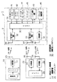
図1に示すように、車両用エンジン制御装置1は、車両2の所有者(運転者)に所持される遠隔操作機11及びイグニッションキー21と、車両2に搭載される通信制御装置31とを備えている。
【0014】
遠隔操作機11は、操作部12、マイクロコンピュータ(マイコン)13及び送信回路14を備えている。
操作部12は、押しボタンスイッチ等からなり、運転者によって手動操作できるようになっている。なお、本実施形態においてこの操作部12は、エンジン始動スイッチとエンジン停止スイッチとからなる2つの押しボタンスイッチによって構成されている。そして、この操作部12が操作されると、マイコン13から操作コード(エンジン始動コードまたはエンジン停止コード)と所定のIDコードとを含むスタータ信号が出力される。このスタータ信号は、送信回路14によって所定周波数の無線信号に変調され、無線信号としてアンテナ15から外部へ出力される。
【0015】
イグニッションキー21は、受信手段としての受信回路22、マイクロコンピュータ(マイコン)23、及び送信手段としての送信回路24を備えている。
受信回路22は、通信制御装置31からのリクエスト信号を受信して、その信号をマイコン23に入力する。マイコン23は、受信回路22からのリクエスト信号が入力されたときに、予め設定された所定のIDコードを含む送信信号(IDコード信号)を出力する。送信回路24は、そのIDコード信号を所定周波数(本実施形態では300MHz)の電波に変調して外部に送信する。なお、受信回路22及び送信回路24にはアンテナ25,26がそれぞれ接続されている。また、本実施形態において受信回路22及びアンテナ25は134kHzの電波を受信可能に形成され、送信回路24及びアンテナ26は300MHzの電波を送信可能に形成されている。
【0016】
一方、通信制御装置31は、第1受信手段としての第1受信回路32、第2受信手段としての第2受信回路33、送信手段としての送信回路34及び制御手段としてのマイクロコンピュータ(マイコン)35を備えている。マイコン35には、シフトポジションセンサ41、カーテシスイッチ42及びエンジン始動装置43が接続されている。シフトポジションセンサ41は、シフト位置がどの位置にあるかを検出し、その検出結果をマイコン35に対して出力する。カーテシスイッチ42は、各ドア及びトランク扉にそれぞれ設けられたスイッチであり、各ドアやトランクの開閉状態を検出し、その検出結果をマイコン35に対して出力する。エンジン始動装置43は、エンジンを自動的に始動・停止させるための装置であり、エンジンの駆動状態をマイコン35に対して出力する。
【0017】
各受信回路32,33及び送信回路34には、それぞれアンテナ36〜38が接続されている。これらアンテナ36〜38は、車両室内の所定箇所に配設されている。
【0018】
第1受信回路32は、前記遠隔操作機11から出力されたスタータ信号をアンテナ36を介して受信して、そのスタータ信号をパルス信号に復調して受信信号を生成するとともに、その受信信号をマイコン35へ出力する。
【0019】
一方、送信回路34は、マイコン35から出力されるリクエスト信号を電波や磁気信号(本実施形態では134kHzの電波)に変換して、アンテナ38を介して車両2の室内の所定領域に出力する。また、第2受信回路33は、イグニッションキー21から出力されたIDコード信号をアンテナ27を介して受信して、そのIDコード信号をパルス信号に復調して受信信号を生成するとともに、その受信信号をマイコン35へ出力する。したがって、これらリクエスト信号の出力領域内においてイグニッションキー21と通信制御装置31との相互通信が可能となっている。
【0020】
マイコン35は、具体的には図示しないCPU、ROM、RAMからなるCPUユニットである。このマイコン35には、予め設定された第1のIDコード及び第2のIDコードが記録されている。第1のIDコードは前記遠隔操作機11に設定されたIDコードと対応して設定されており、第2のIDコードは前記イグニッションキー21に設定されたIDコードと対応して設定されている。
【0021】
次に、こうしたマイコン35によって行われる処理を、図2に示すフローチャートに従って説明する。なお、この処理はマイコン35を構成するROM内に格納されたプログラムに基づいて所定時間毎に繰り返し実行される。また、前記プログラムは、ROM以外のコンピュータ読み出し可能な記録媒体に記録されていてもよい。
【0022】
まず、ステップS1においてマイコン35は、遠隔操作機11からのスタータ信号を受信したか否かを判断する。そして、マイコン35は、スタータ信号を受信したときにステップS2の処理へ移行し、スタータ信号を受信しないときにはここでの処理を一旦終了する。すなわち、マイコン35は、遠隔操作機11からのスタータ信号受信を待機する状態となっている。より詳しくは、ステップS1においてマイコン35は、スタータ信号を受信したときにスタータ信号に含まれるIDコードと前記第1のIDコードとを比較し、それらが一致したときにステップS2の処理へ移行する。また、マイコン35は、スタータ信号を受信しないとき、及び、各IDコード同士が一致しないときにはここでの処理を一旦終了する。
【0023】
ステップS2においてマイコン35は、シフトポジションセンサ41からの出力信号をモニタし、シフトポジションが「P」レンジまたは「N」レンジに位置しているか否かを判断する。そして、マイコン35は、シフトポジションが「P」レンジまたは「N」レンジに位置しているときにはステップS3の処理へ移行し、そうでないときにはここでの処理を一旦終了する。
【0024】
ステップS3においてマイコン35は、カーテシスイッチ42からの出力信号をモニタし、各ドア及びトランクが閉状態であるか否かを判断する。そして、マイコン35は、各ドア及びトランクが閉状態であるときにステップS4の処理へ移行し、各ドア及びトランクのうち少なくとも1つが開状態であるときにはここでの処理を一旦終了する。
【0025】
ステップS4においてマイコン35は、送信回路34に対してリクエスト信号を出力する。
続くステップS5においてマイコン35は、イグニッションキー21からのIDコード信号に含まれるIDコードと前記第2のIDコードとを比較し、それらが一致したときにはここでの処理を一旦終了する。また、マイコン35は、それらIDコード同士が一致しないときにはステップS6の処理へ移行する。すなわち、マイコン35は、イグニッションキー21からのIDコード信号を受信できないときにもステップS6の処理へ移行する。
【0026】
そして、ステップS6において、マイコン35は、エンジン始動装置43に対して所定の制御信号を出力する。詳しくは、マイコン35は、スタータ信号に含まれる操作コードがエンジン始動コードであれば、エンジン始動装置43に対してエンジンを始動させるための制御信号を出力する。また、マイコン35は、スタータ信号に含まれる操作コードがエンジン停止コードであれば、エンジン始動装置43に対してエンジンを停止させるための制御信号を出力する。
【0027】
次に、こうした処理に基づくマイコン35の動作態様を図3に従って説明する。なお、この動作態様は、シフトポジションが「P」レンジまたは「N」レンジに位置するとともに、ドア及びトランクが閉状態となっていることを前提とする。
【0028】
まず、マイコン35は、同図にポイントP1で示すように遠隔操作機11からのスタータ信号を受信すると、ポイントP2で示すようにリクエスト信号を出力する。そして、ポイントP3〜P4の間でイグニッションキー21からのIDコード信号を受信できない場合または各IDコード同士が一致しない場合、マイコン35はポイントP4で示すように制御信号を出力する。すなわち、マイコン35は、スタータ信号の受信時にイグニッションキー21が車両2内に存在しない場合に、エンジン始動装置43に対して制御信号を出力する。このため、スタータ信号に基づいてエンジンが自動的に始動または停止される。なお、マイコン35は、スタータ信号を受信したときにのみリクエスト信号を出力する。すなわち、リクエスト信号は、スタータ信号の受信をトリガとして出力される。
【0029】
また、マイコン35は、同図にポイントP5で示すようにスタータ信号を受信すると、ポイントP6でリクエスト信号を出力する。そして、ポイントP7で示すようにIDコード信号を受信して各IDコード同士が一致した場合、マイコン35はポイントP8で示すように制御信号の出力を禁止する。つまり、イグニッションキー21が車両2内に存在する場合には、マイコン35は、スタータ信号を受信したにもかかわらず、エンジンを自動的に始動または停止させないようにする。
【0030】
したがって、本実施形態によれば以下のような効果を得ることができる。
(1)イグニッションキー21は通信制御装置31と双方向通信できるようになっている。そして、通信制御装置31は、遠隔操作機11からのスタータ信号を受信した際にイグニッションキー21からのIDコード信号を受信したときには、遠隔操作機11によるエンジンの遠隔制御(遠隔始動または遠隔停止)を禁止するようになっている。イグニッションキー21と通信制御装置31とは車両2の室内で通信可能となっているため、イグニッションキー21の所持者が車両2内に存在するときには、エンジンの遠隔制御が禁止される。すなわち、イグニッションキー21の所持者が車両2内に存在するにもかかわらず遠隔操作機11によってエンジンが遠隔制御されてしまうのを防止することができる。このため、車外にいる第三者によって遠隔操作機11が操作されてしまったときなど、本来遠隔操作を不要とする状態であるにもかかわらず遠隔操作によってエンジンが制御されてしまうのを防止することができる。
【0031】
(2)リクエスト信号は、遠隔操作機11からのスタータ信号が受信されたときにのみ出力されるようになっている。このため、リクエスト信号の無駄な出力が防止され、車両バッテリの電力消耗を抑制することができる。
(第2実施形態)
次に、本発明を具体化した第2実施形態を図4及び図5に基づいて説明する。ここでは第1実施形態と相違する点を主に述べ、共通する点については同一部材番号を付すのみとしてその説明を省略する。
【0032】
本実施形態においては、車両2の室内に、図示しないエンジン始動スイッチが設けられている。そして、エンジン始動スイッチが所定の条件下で操作されたときにエンジンが始動・停止するようになっている。また、図5に示すように、マイコン35がリクエスト信号を所定時間T毎に間欠的に出力するようになっている。
【0033】
こうした車両用エンジン制御装置1において前記第1実施形態と異なる主な点は、マイコン35の処理内容についてである。そこで、本実施形態のマイコン35によって行われる処理を、図4に示すフローチャートに従って説明する。
【0034】
まず、ステップS11においてマイコン35は、送信回路34に対してリクエスト信号を所定時間T毎に間欠的に出力する。
続くステップS12においてマイコン35は、イグニッションキー21からのIDコード信号に含まれるIDコードと前記第2のIDコードとを比較し、それらが一致したときにはステップS13の処理へ移行する。
【0035】
そして、ステップS13においてマイコン35は、エンジン始動装置43に対してエンジンの始動を許可するためのエンジン始動許可信号を出力し、ここでの処理を一旦終了する。よって、このエンジン始動許可信号が出力されている間にのみイグニッションキー21によるエンジン始動が可能となる。つまり、エンジン始動許可信号が出力されている間に前記エンジン始動スイッチが操作されたときにエンジンが始動する。
【0036】
また、マイコン35は、ステップS12において各IDコード同士が一致しないときにはステップS14の処理へ移行する。すなわち、マイコン35は、イグニッションキー21からのIDコード信号をできないときにもステップS14の処理へ移行する。
【0037】
そして、ステップS14においてマイコン35は、遠隔操作機11からのスタータ信号を受信したか否かを判断する。ここで、マイコン35は、スタータ信号を受信したときにステップS15の処理へ移行し、スタータ信号を受信しないときにはここでの処理を一旦終了する。より詳しくは、ステップS1においてマイコン35は、スタータ信号を受信したときにスタータ信号に含まれるIDコードと前記第1のIDコードとを比較し、それらが一致したときにステップS15の処理へ移行する。すなわち、マイコン35は、イグニッションキー21が車両2の室内に存在しないときに、遠隔操作機11からのスタータ信号受信を待機する状態となる。また、マイコン35は、各IDコード同士が一致しないとき、及び、スタータ信号を受信しないときにはここでの処理を一旦終了する。
【0038】
ステップS15においてマイコン35は、シフトポジションセンサ41からの出力信号をモニタし、シフトポジションが「P」レンジまたは「N」レンジに位置しているか否かを判断する。そして、マイコン35は、シフトポジションが「P」レンジまたは「N」レンジに位置しているときにはステップS16の処理へ移行し、そうでないときにはここでの処理を一旦終了する。
【0039】
ステップS16においてマイコン35は、カーテシスイッチ42からの出力信号をモニタし、各ドア及びトランクが閉状態であるか否かを判断する。そして、マイコン35は、各ドア及びトランクが閉状態であるときにステップS17の処理へ移行し、各ドア及びトランクのうち少なくとも1つが開状態であるときにはここでの処理を一旦終了する。
【0040】
そして、ステップS17において、マイコン35は、エンジン始動装置43に対して所定の制御信号を出力する。詳しくは、マイコン35は、スタータ信号に含まれる操作コードがエンジン始動コードであれば、エンジン始動装置43に対してエンジンを始動させるための制御信号を出力する。また、マイコン35は、スタータ信号に含まれる操作コードがエンジン停止コードであれば、エンジン始動装置43に対してエンジンを停止させるための制御信号を出力する。
【0041】
次に、こうした処理に基づくマイコン35の動作態様を図5に従って説明する。なお、この動作態様は、シフトポジションが「P」レンジまたは「N」レンジに位置するとともに、ドア及びトランクが閉状態となっていることを前提とする。
【0042】
まず、マイコン35は、同図にポイントP1で示すようにリクエスト信号を出力する。そして、ポイントP2で示すように、イグニッションキー21からのIDコード信号を受信して各IDコード同士が一致した場合、マイコン35は同ポイントP2で示すようにエンジン始動装置43に対してエンジン始動許可信号を出力する。このエンジン始動許可信号はIDコード信号を受信している間出力される。すなわち、同図に示すように、IDコード信号をポイントP2からP5までの間受信している場合にはポイントP2〜P5の間エンジン始動許可信号が出力される。そして、マイコン35は、ポイントP3で示すように、ポイントP2〜P5の間で遠隔操作機11からのスタータ信号を受信すると、ポイントP4で示すように制御信号の出力を禁止する。つまり、マイコン35は、イグニッションキー21が車両2内に存在する場合には、イグニッションキー21(本実施形態においてはエンジン始動スイッチ)によってのみエンジンの始動できるように制御する。しかも、エンジンは、イグニッションキー21のIDコードと通信制御装置31の第2のIDコードとが一致したときにのみ始動可能であるため、車両用エンジン制御装置1は、スマートイグニッション装置として機能する。
【0043】
また、マイコン35は、ポイントP6で示すようにエンジン始動許可信号を出力していないときにスタータ信号を受信すると、ポイントP7で示すようにエンジン始動装置43に対して制御信号を出力する。すなわち、マイコン35は、スタータ信号の受信時にイグニッションキー21が車両2内に存在しない場合に、制御信号を出力する。このため、スタータ信号に基づいてエンジンが自動的に始動または停止される。
【0044】
したがって、本実施形態によれば、前記第1実施形態における上記(1)に記載の効果に加えて、以下のような効果を得ることができる。
(3)マイコン35は、車両2の室内にイグニッションキー21が存在するときにエンジンを始動可能状態にする。このため、遠隔操作機11以外の操作によってエンジンを始動させる際には、イグニッションキー21が必須となる。よって、偽造キーなどによる不正なエンジン始動を禁止することができ、車両の防犯性を向上させることができる。
【0045】
(4)エンジンの始動可能状態では、エンジン始動スイッチが操作されたときにエンジンが始動するようになっている。すなわち、車両用エンジン制御装置は、スマートイグニッション装置として機能する。このため、エンジンを始動させる際にイグニッションキー21をキースイッチに挿入する必要がなくなり、車両2の操作性を向上させることができる。
【0046】
しかも、こうしたスマートイグニッション装置として機能させるために、車両用エンジン制御装置1のハードウェア的な構成の変更・追加をする必要がなく、コストの高騰を防止することもできる。
【0047】
なお、本発明の実施形態は以下のように変更してもよい。
・ 前記各実施形態においてマイコン35には、シフトポジションセンサ41、カーテシスイッチ42及びエンジン始動装置43が接続されている。そして、マイコン35は、遠隔操作機11からのスタータ信号の受信時に、シフトポジションが「P」,「N」レンジにあり、かつドア及びトランクが閉状態であるときにエンジンを始動させるようになっている。しかし、図1に2点鎖線で示すように、マイコン35にパーキングブレーキセンサ44及びキースイッチ45をさらに接続する。そして、前記条件に加えて、パーキングブレーキセンサ44がON状態のとき及びキースイッチ45がOFF状態のときにのみエンジンを始動させるようにしてもよい。なお、パーキングブレーキセンサ44はパーキングブレーキが作動しているときにON状態となり、キースイッチ45はキーシリンダにイグニッションキー21が挿入されているときにON状態となるものとする。このようにすれば、より安全な状態でのみ遠隔操作機11によるエンジン始動を可能とすることができる。
【0048】
・ 前記各実施形態において、図1に2点鎖線で示すように、マイコン35にドアロック駆動装置46を接続する。また、通信制御装置31の送信回路34から、車両室内と車両外部とを選択的にリクエスト信号を出力できるようにする。そして、車両外部へのリクエスト信号の出力時にマイコン35がIDコード信号を受信した際に、ドアロック駆動装置46を駆動してドア錠を自動的に解錠させるようにする。また、車両外部へのリクエスト信号の出力時にマイコン35がIDコード信号を受信できないときにはドア錠を自動的に施錠させるようにする。このようにすれば、車両用エンジン制御装置1をスマートエントリ装置として機能させることができ、車両2の操作性をより向上させることができる。
【0049】
・ 前記第2実施形態では、車両2の室内にエンジン始動スイッチを設け、イグニッションキー21からのIDコード信号をマイコン35が受信している間はエンジン始動スイッチの操作によってエンジンを始動できるようになっている。つまり、車両用エンジン制御装置1をスマートイグニッション装置として機能させるようになっている。しかし、エンジン始動スイッチは必ずしも必要ではない。つまり、イグニッションキー21をキーシリンダに挿入し、同キー21を回転させることによってエンジンを始動させるといった従来の構造であってもよい。このようにすれば、車両用エンジン制御装置1にイモビライザ機能を持たせることができ、車両2の防犯性を高めることができる。
【0050】
次に、特許請求の範囲に記載された技術的思想のほかに、前述した実施形態によって把握される技術的思想を以下に列挙する。
(1) 遠隔操作機と、その遠隔操作機からの無線信号を受信したときにエンジンを自動的に始動する通信制御装置とを備えた車両用エンジン制御装置において、イグニッションキーに前記通信制御装置と相互通信可能な通信手段を設け、前記通信制御装置は、車両室内の所定領域にリクエスト信号を出力し、前記リクエスト信号に応答した前記イグニッションキーからの送信信号を受信したときには、前記遠隔操作機によるエンジンの遠隔制御を禁止すること。
【0051】
(2) 遠隔操作機と、その遠隔操作機からの無線信号を受信したときにエンジンを自動的に始動する通信制御装置とを備えた車両用エンジン制御装置におけるエンジン始動制御方法において、前記通信制御装置によって車両室内にイグニッションキーが存在するか否かを検出し、車両室内にイグニッションキーが存在するときには、前記遠隔操作機によるエンジンの遠隔制御を禁止すること。
【0052】
【発明の効果】
以上詳述したように、請求項1〜3に記載の発明によれば、本来遠隔操作を不要とする状態であるにもかかわらず、遠隔操作によってエンジンが制御されてしまうのを防止することができる。
【0053】
請求項2に記載の発明によれば、車両バッテリの電力消耗を抑制することができる。
請求項3に記載の発明によれば、車両の防犯性を向上させることができる。
【図面の簡単な説明】
【図1】本発明の第1実施形態の車両用エンジン制御装置の概略構成を示すブロック図。
【図2】同実施形態の制御手段によって実行される処理を示すフローチャート。
【図3】同実施形態の制御手段によって実行される制御態様の一例を示すタイムチャート。
【図4】第2実施形態の制御手段によって実行される処理を示すフローチャート。
【図5】第2実施形態の制御手段によって実行される制御態様の一例を示すタイムチャート。
【符号の説明】
1…車両用エンジン制御装置、2…車両、11…遠隔操作機、21…イグニッションキー、22…受信手段としての受信回路、23…マイクロコンピュータ(マイコン)、24…送信手段としての送信回路、31…通信制御装置、32…第1受信手段としての第1受信回路、33…第2受信手段としての第2受信回路、34…リクエスト信号出力手段としての送信回路、35…制御手段としてのマイクロコンピュータ(マイコン)、43…エンジン始動装置。[0001]
BACKGROUND OF THE INVENTION
The present invention relates to a vehicle engine control device that starts a vehicle engine by remote control.
[0002]
[Prior art]
2. Description of the Related Art Conventionally, for the purpose of improving the operability of a vehicle, a vehicle engine control device that starts an engine by remote operation has been proposed.
[0003]
This type of vehicle engine control device is configured by a remote controller carried by a driver and a communication control device mounted on the vehicle. When the driver operates the remote controller, a radio signal including a predetermined ID code is output from the remote controller. The communication control device is configured to be able to receive the radio signal up to a position separated from the vehicle by a predetermined distance. When receiving the radio signal, the ID code of the radio signal and an ID code set in advance in the radio signal Compare As a result, when the ID codes match, the communication control apparatus automatically starts the engine. For this reason, when performing warm-up operation in winter, for example, it is not necessary to go to the vehicle to simply start the engine. Therefore, the operability of the vehicle is improved.
[0004]
[Problems to be solved by the invention]
However, in the conventional vehicle engine starter, even if a third party outside the vehicle operates the remote control device with the driver getting in the vehicle without having the remote control device, the engine can be started. Is possible. For this reason, the engine may be started regardless of the driver's will.
[0005]
The present invention has been made in view of such circumstances, and an object of the present invention is a vehicle capable of preventing the engine from being controlled by remote operation even though the remote operation is originally unnecessary. An engine control device for a vehicle is provided.
[0006]
[Means for Solving the Problems]
In order to solve the above-described problem, in the invention according to claim 1, in the case where the remote control device that transmits a radio signal including a predetermined ID code to the outside and the radio controller that is mounted in the vehicle and receives the radio signal A request output from the communication control device to an ignition key in a vehicle engine control device comprising a communication control device that automatically starts or stops the engine when the ID code matches a preset ID code A receiving unit configured to receive a signal; and a transmitting unit configured to transmit a predetermined transmission signal to the outside when the request signal is received, wherein the communication control device receives a radio signal output from the remote controller. Receiving means; request signal output means for transmitting the request signal to at least a predetermined area in the vehicle compartment; and the ignition And a second receiving means for receiving a transmission signal transmitted from the engine, and a control means for prohibiting remote control of the engine by the remote controller when receiving a transmission signal from at least the ignition key. To do.
[0007]
According to a second aspect of the present invention, in the vehicle engine control device according to the first aspect, the communication control device outputs the request signal using the radio signal as a trigger when receiving the radio signal from the remote controller. The gist is that the request signal is not output when the wireless signal is not received.
[0008]
According to a third aspect of the present invention, in the vehicle engine control device according to the first aspect, the communication control device outputs the request signal at every predetermined time, and outputs from the ignition key in response to the request signal. The gist is to make the engine startable when a transmission signal is received, and prohibit remote control of the engine when a radio signal is received from the remote controller in the engine startable state.
[0009]
The “action” of the present invention will be described below.
According to the first aspect of the present invention, the ignition key can be bidirectionally communicated with the communication control device. The communication control device prohibits remote control (remote start or stop) of the engine by the remote controller when at least a transmission signal from the ignition key is received. Since the ignition key and the communication control device can communicate with each other in the vehicle compartment, remote control of the engine is prohibited when the owner of the ignition key exists in the vehicle. That is, the engine is not remotely controlled by the remote controller even though the ignition key holder is present in the vehicle.
[0010]
According to the second aspect of the present invention, the request signal is output only when a radio signal from the remote controller is received. For this reason, useless output of the request signal is prevented, and power consumption of the vehicle battery can be suppressed.
[0011]
According to the third aspect of the present invention, in addition to the operation of the first aspect, the control means of the communication control device makes the engine startable when the ignition key is present in the vehicle. For this reason, when starting the engine by an operation other than the remote controller, an ignition key is essential. Therefore, unauthorized engine start is prohibited and the crime prevention property of the vehicle is improved.
[0012]
DETAILED DESCRIPTION OF THE INVENTION
(First embodiment)
Hereinafter, a first embodiment of the present invention will be described in detail with reference to FIGS.
[0013]
As shown in FIG. 1, the vehicular engine control device 1 includes a
[0014]
The
The
[0015]
The
The
[0016]
On the other hand, the
[0017]
[0018]
The
[0019]
On the other hand, the
[0020]
The microcomputer 35 is a CPU unit that includes a CPU, a ROM, and a RAM (not shown). The microcomputer 35 records a first ID code and a second ID code that are set in advance. The first ID code is set in correspondence with the ID code set in the
[0021]
Next, processing performed by the microcomputer 35 will be described with reference to the flowchart shown in FIG. This process is repeatedly executed at predetermined intervals based on a program stored in the ROM constituting the microcomputer 35. The program may be recorded on a computer-readable recording medium other than the ROM.
[0022]
First, in step S <b> 1, the microcomputer 35 determines whether a starter signal from the
[0023]
In step S2, the microcomputer 35 monitors the output signal from the
[0024]
In step S3, the microcomputer 35 monitors the output signal from the
[0025]
In step S <b> 4, the microcomputer 35 outputs a request signal to the
In the subsequent step S5, the microcomputer 35 compares the ID code included in the ID code signal from the
[0026]
In step S <b> 6, the microcomputer 35 outputs a predetermined control signal to the
[0027]
Next, the operation mode of the microcomputer 35 based on such processing will be described with reference to FIG. This operation mode is based on the premise that the shift position is in the “P” range or the “N” range and the door and the trunk are closed.
[0028]
First, when receiving a starter signal from the
[0029]
When the microcomputer 35 receives a starter signal as indicated by a point P5 in the figure, it outputs a request signal at a point P6. When the ID code signal is received as indicated by point P7 and the ID codes match each other, the microcomputer 35 prohibits the output of the control signal as indicated by point P8. That is, when the
[0030]
Therefore, according to the present embodiment, the following effects can be obtained.
(1) The
[0031]
(2) The request signal is output only when the starter signal from the
(Second Embodiment)
Next, a second embodiment embodying the present invention will be described with reference to FIGS. Here, points different from the first embodiment will be mainly described, and common points will be simply denoted by the same member numbers, and description thereof will be omitted.
[0032]
In the present embodiment, an engine start switch (not shown) is provided in the
[0033]
In such a vehicular engine control apparatus 1, the main difference from the first embodiment is the processing content of the microcomputer 35. Therefore, processing performed by the microcomputer 35 of the present embodiment will be described with reference to the flowchart shown in FIG.
[0034]
First, in step S <b> 11, the microcomputer 35 intermittently outputs request signals to the
In subsequent step S12, the microcomputer 35 compares the ID code included in the ID code signal from the
[0035]
In step S13, the microcomputer 35 outputs an engine start permission signal for permitting the
[0036]
The microcomputer 35 proceeds to the process of step S14 when the ID codes do not match in step S12. In other words, the microcomputer 35 proceeds to the process of step S14 even when the ID code signal from the
[0037]
In step S <b> 14, the microcomputer 35 determines whether a starter signal from the
[0038]
In step S15, the microcomputer 35 monitors the output signal from the
[0039]
In step S16, the microcomputer 35 monitors the output signal from the
[0040]
In step S <b> 17, the microcomputer 35 outputs a predetermined control signal to the
[0041]
Next, the operation mode of the microcomputer 35 based on such processing will be described with reference to FIG. This operation mode is based on the premise that the shift position is in the “P” range or the “N” range and the door and the trunk are closed.
[0042]
First, the microcomputer 35 outputs a request signal as indicated by a point P1 in FIG. When the ID code signal from the
[0043]
If the microcomputer 35 receives the starter signal when the engine start permission signal is not output as indicated by point P6, it outputs a control signal to the
[0044]
Therefore, according to this embodiment, in addition to the effect described in the above (1) in the first embodiment, the following effect can be obtained.
(3) The microcomputer 35 makes the engine startable when the
[0045]
(4) In the engine startable state, the engine is started when the engine start switch is operated. That is, the vehicle engine control device functions as a smart ignition device. For this reason, it is not necessary to insert the
[0046]
In addition, in order to function as such a smart ignition device, it is not necessary to change or add a hardware configuration of the vehicle engine control device 1, and it is possible to prevent an increase in cost.
[0047]
In addition, you may change embodiment of this invention as follows.
In each of the embodiments, the
[0048]
In each of the above embodiments, a door
[0049]
In the second embodiment, an engine start switch is provided in the
[0050]
Next, in addition to the technical ideas described in the claims, the technical ideas grasped by the embodiment described above are listed below.
(1) In a vehicle engine control device comprising a remote control device and a communication control device that automatically starts an engine when a radio signal is received from the remote control device, the communication control device Communication means capable of mutual communication is provided, and the communication control device outputs a request signal to a predetermined area in a vehicle compartment and receives a transmission signal from the ignition key in response to the request signal. Prohibit remote control of the engine.
[0051]
(2) In the engine start control method for a vehicle engine control device comprising a remote control device and a communication control device for automatically starting the engine when receiving a radio signal from the remote control device, the communication control The device detects whether or not an ignition key is present in the vehicle compartment, and prohibits remote control of the engine by the remote controller when the ignition key is present in the vehicle compartment.
[0052]
【The invention's effect】
As described above in detail, according to the first to third aspects of the invention, it is possible to prevent the engine from being controlled by the remote operation even though the remote operation is originally unnecessary. it can.
[0053]
According to the second aspect of the present invention, power consumption of the vehicle battery can be suppressed.
According to invention of
[Brief description of the drawings]
FIG. 1 is a block diagram showing a schematic configuration of a vehicle engine control apparatus according to a first embodiment of the present invention.
FIG. 2 is a flowchart showing processing executed by the control unit of the embodiment.
FIG. 3 is a time chart showing an example of a control mode executed by the control unit of the embodiment.
FIG. 4 is a flowchart showing processing executed by a control unit of the second embodiment.
FIG. 5 is a time chart showing an example of a control mode executed by the control unit of the second embodiment.
[Explanation of symbols]
DESCRIPTION OF SYMBOLS 1 ... Vehicle engine control apparatus, 2 ... Vehicle, 11 ... Remote control machine, 21 ... Ignition key, 22 ... Receiving circuit as receiving means, 23 ... Microcomputer (microcomputer), 24 ... Transmitting circuit as transmitting means, 31 ... Communication control device, 32 ... first receiving circuit as first receiving means, 33 ... second receiving circuit as second receiving means, 34 ... transmitting circuit as request signal output means, 35 ... microcomputer as control means (Microcomputer), 43 ... engine starter.
Claims (3)
イグニッションキーに、前記通信制御装置から出力されるリクエスト信号を受信する受信手段と、該リクエスト信号の受信時に所定の送信信号を外部に送信する送信手段とを設け、
前記通信制御装置は、前記遠隔操作機から出力された無線信号を受信する第1受信手段と、少なくとも車両室内における所定領域に前記リクエスト信号を送信するリクエスト信号出力手段と、前記イグニッションキーから送信された送信信号を受信する第2受信手段と、少なくとも前記イグニッションキーからの送信信号を受信したときに前記遠隔操作機によるエンジンの遠隔制御を禁止する制御手段とを備えることを特徴とする車両用エンジン制御装置。A remote control device that transmits a radio signal including a predetermined ID code to the outside, and an engine that is mounted in a vehicle and automatically receives the radio signal when the ID code matches a preset ID code. In a vehicle engine control device comprising a communication control device for starting or stopping automatically,
The ignition key is provided with receiving means for receiving a request signal output from the communication control device, and transmitting means for transmitting a predetermined transmission signal to the outside when the request signal is received,
The communication control device is transmitted from a first receiving means for receiving a radio signal output from the remote controller, a request signal output means for transmitting the request signal to at least a predetermined area in a vehicle compartment, and an ignition key. A vehicle engine comprising: a second receiving means for receiving the transmitted signal; and a control means for prohibiting remote control of the engine by the remote controller when receiving a transmission signal from at least the ignition key. Control device.
Priority Applications (1)
| Application Number | Priority Date | Filing Date | Title |
|---|---|---|---|
| JP2000387269A JP4377049B2 (en) | 2000-12-20 | 2000-12-20 | Vehicle engine control device |
Applications Claiming Priority (1)
| Application Number | Priority Date | Filing Date | Title |
|---|---|---|---|
| JP2000387269A JP4377049B2 (en) | 2000-12-20 | 2000-12-20 | Vehicle engine control device |
Publications (2)
| Publication Number | Publication Date |
|---|---|
| JP2002188505A JP2002188505A (en) | 2002-07-05 |
| JP4377049B2 true JP4377049B2 (en) | 2009-12-02 |
Family
ID=18854236
Family Applications (1)
| Application Number | Title | Priority Date | Filing Date |
|---|---|---|---|
| JP2000387269A Expired - Fee Related JP4377049B2 (en) | 2000-12-20 | 2000-12-20 | Vehicle engine control device |
Country Status (1)
| Country | Link |
|---|---|
| JP (1) | JP4377049B2 (en) |
Families Citing this family (7)
| Publication number | Priority date | Publication date | Assignee | Title |
|---|---|---|---|---|
| JP2004218538A (en) * | 2003-01-15 | 2004-08-05 | Fujitsu Ten Ltd | Remote starting devise for vehicle |
| JP4705317B2 (en) | 2003-04-16 | 2011-06-22 | 株式会社東海理化電機製作所 | Switch device, security system |
| JP4217520B2 (en) | 2003-04-16 | 2009-02-04 | 株式会社東海理化電機製作所 | Switch device |
| JP2008157030A (en) * | 2006-12-20 | 2008-07-10 | Tokai Rika Co Ltd | Remote engine start controller and vehicle control device |
| JP2008215136A (en) * | 2007-03-01 | 2008-09-18 | Denso Corp | Engine start device and engine start system |
| CN103419749A (en) * | 2013-08-28 | 2013-12-04 | 大陆汽车电子(长春)有限公司 | Switching device used for controlling engine of vehicle |
| JP2017207031A (en) * | 2016-05-20 | 2017-11-24 | 三菱マヒンドラ農機株式会社 | Engine start device for work vehicle |
-
2000
- 2000-12-20 JP JP2000387269A patent/JP4377049B2/en not_active Expired - Fee Related
Also Published As
| Publication number | Publication date |
|---|---|
| JP2002188505A (en) | 2002-07-05 |
Similar Documents
| Publication | Publication Date | Title |
|---|---|---|
| JP4476062B2 (en) | In-vehicle control device | |
| JP4479573B2 (en) | Vehicle anti-theft device | |
| US7274979B2 (en) | Vehicle anti-theft device | |
| JP2697605B2 (en) | Vehicle antitheft device and method for registering ID number of vehicle antitheft device | |
| JP4130335B2 (en) | Vehicle remote control system and portable device for vehicle remote control system | |
| JP4213719B2 (en) | In-vehicle device remote control device | |
| JP4232129B2 (en) | Keyless entry system | |
| JP2003221954A (en) | Remote control system for on-vehicle equipment | |
| JP4377049B2 (en) | Vehicle engine control device | |
| JP3799961B2 (en) | Electronic key device for vehicle | |
| JP4377039B2 (en) | Remote control device for vehicle | |
| JPH1191507A (en) | On-vehicle remote control device | |
| EP3470275B1 (en) | Wireless communication system | |
| JPH10287208A (en) | Steering lock system for vehicle | |
| US7378752B2 (en) | Vehicle antitheft device | |
| JP4095295B2 (en) | Vehicle locking / unlocking control device and vehicle locking / unlocking control system | |
| JP3520786B2 (en) | In-vehicle equipment remote control device | |
| US7710244B2 (en) | Remote engine starting system and method | |
| JP4264193B2 (en) | In-vehicle device remote control device | |
| JP2002213124A (en) | Locking/unlocking device for vehicle | |
| JP3552557B2 (en) | Vehicle remote control device | |
| JP4313505B2 (en) | Remote control device for vehicle | |
| JP2001329730A (en) | Remote controller for vehicle | |
| JP2006103355A (en) | Smart keyless control device | |
| JP2004098920A (en) | Engine drive control device |
Legal Events
| Date | Code | Title | Description |
|---|---|---|---|
| A621 | Written request for application examination |
Free format text: JAPANESE INTERMEDIATE CODE: A621 Effective date: 20070413 |
|
| A131 | Notification of reasons for refusal |
Free format text: JAPANESE INTERMEDIATE CODE: A131 Effective date: 20090203 |
|
| TRDD | Decision of grant or rejection written | ||
| A01 | Written decision to grant a patent or to grant a registration (utility model) |
Free format text: JAPANESE INTERMEDIATE CODE: A01 Effective date: 20090901 |
|
| A01 | Written decision to grant a patent or to grant a registration (utility model) |
Free format text: JAPANESE INTERMEDIATE CODE: A01 |
|
| A61 | First payment of annual fees (during grant procedure) |
Free format text: JAPANESE INTERMEDIATE CODE: A61 Effective date: 20090910 |
|
| R150 | Certificate of patent or registration of utility model |
Free format text: JAPANESE INTERMEDIATE CODE: R150 Ref document number: 4377049 Country of ref document: JP Free format text: JAPANESE INTERMEDIATE CODE: R150 |
|
| FPAY | Renewal fee payment (event date is renewal date of database) |
Free format text: PAYMENT UNTIL: 20120918 Year of fee payment: 3 |
|
| FPAY | Renewal fee payment (event date is renewal date of database) |
Free format text: PAYMENT UNTIL: 20120918 Year of fee payment: 3 |
|
| FPAY | Renewal fee payment (event date is renewal date of database) |
Free format text: PAYMENT UNTIL: 20130918 Year of fee payment: 4 |
|
| FPAY | Renewal fee payment (event date is renewal date of database) |
Free format text: PAYMENT UNTIL: 20140918 Year of fee payment: 5 |
|
| LAPS | Cancellation because of no payment of annual fees |