JP4366390B2 - Bicycle handlebar assembly - Google Patents
Bicycle handlebar assembly Download PDFInfo
- Publication number
- JP4366390B2 JP4366390B2 JP2006279666A JP2006279666A JP4366390B2 JP 4366390 B2 JP4366390 B2 JP 4366390B2 JP 2006279666 A JP2006279666 A JP 2006279666A JP 2006279666 A JP2006279666 A JP 2006279666A JP 4366390 B2 JP4366390 B2 JP 4366390B2
- Authority
- JP
- Japan
- Prior art keywords
- brake
- speed change
- handlebar
- change operation
- operation unit
- Prior art date
- Legal status (The legal status is an assumption and is not a legal conclusion. Google has not performed a legal analysis and makes no representation as to the accuracy of the status listed.)
- Expired - Fee Related
Links
- 230000008859 change Effects 0.000 claims description 73
- 238000005452 bending Methods 0.000 description 5
- 230000005540 biological transmission Effects 0.000 description 5
- 230000007246 mechanism Effects 0.000 description 4
- 210000003811 finger Anatomy 0.000 description 2
- 230000007935 neutral effect Effects 0.000 description 2
- 210000003813 thumb Anatomy 0.000 description 2
- 241000270281 Coluber constrictor Species 0.000 description 1
- 230000001133 acceleration Effects 0.000 description 1
- 230000007423 decrease Effects 0.000 description 1
- 238000010586 diagram Methods 0.000 description 1
- 210000005069 ears Anatomy 0.000 description 1
- OQZCSNDVOWYALR-UHFFFAOYSA-N flurochloridone Chemical compound FC(F)(F)C1=CC=CC(N2C(C(Cl)C(CCl)C2)=O)=C1 OQZCSNDVOWYALR-UHFFFAOYSA-N 0.000 description 1
- 239000004973 liquid crystal related substance Substances 0.000 description 1
- 238000000034 method Methods 0.000 description 1
- 230000002093 peripheral effect Effects 0.000 description 1
- 230000008569 process Effects 0.000 description 1
- 230000009467 reduction Effects 0.000 description 1
- 230000004044 response Effects 0.000 description 1
Images


Classifications
-
- B—PERFORMING OPERATIONS; TRANSPORTING
- B62—LAND VEHICLES FOR TRAVELLING OTHERWISE THAN ON RAILS
- B62K—CYCLES; CYCLE FRAMES; CYCLE STEERING DEVICES; RIDER-OPERATED TERMINAL CONTROLS SPECIALLY ADAPTED FOR CYCLES; CYCLE AXLE SUSPENSIONS; CYCLE SIDE-CARS, FORECARS, OR THE LIKE
- B62K23/00—Rider-operated controls specially adapted for cycles, i.e. means for initiating control operations, e.g. levers, grips
- B62K23/02—Rider-operated controls specially adapted for cycles, i.e. means for initiating control operations, e.g. levers, grips hand actuated
- B62K23/06—Levers
-
- B—PERFORMING OPERATIONS; TRANSPORTING
- B62—LAND VEHICLES FOR TRAVELLING OTHERWISE THAN ON RAILS
- B62L—BRAKES SPECIALLY ADAPTED FOR CYCLES
- B62L3/00—Brake-actuating mechanisms; Arrangements thereof
- B62L3/02—Brake-actuating mechanisms; Arrangements thereof for control by a hand lever
-
- B—PERFORMING OPERATIONS; TRANSPORTING
- B62—LAND VEHICLES FOR TRAVELLING OTHERWISE THAN ON RAILS
- B62M—RIDER PROPULSION OF WHEELED VEHICLES OR SLEDGES; POWERED PROPULSION OF SLEDGES OR SINGLE-TRACK CYCLES; TRANSMISSIONS SPECIALLY ADAPTED FOR SUCH VEHICLES
- B62M25/00—Actuators for gearing speed-change mechanisms specially adapted for cycles
- B62M25/08—Actuators for gearing speed-change mechanisms specially adapted for cycles with electrical or fluid transmitting systems
-
- B—PERFORMING OPERATIONS; TRANSPORTING
- B62—LAND VEHICLES FOR TRAVELLING OTHERWISE THAN ON RAILS
- B62M—RIDER PROPULSION OF WHEELED VEHICLES OR SLEDGES; POWERED PROPULSION OF SLEDGES OR SINGLE-TRACK CYCLES; TRANSMISSIONS SPECIALLY ADAPTED FOR SUCH VEHICLES
- B62M25/00—Actuators for gearing speed-change mechanisms specially adapted for cycles
- B62M2025/003—Actuators for gearing speed-change mechanisms specially adapted for cycles with gear indicating means, e.g. a display
-
- Y—GENERAL TAGGING OF NEW TECHNOLOGICAL DEVELOPMENTS; GENERAL TAGGING OF CROSS-SECTIONAL TECHNOLOGIES SPANNING OVER SEVERAL SECTIONS OF THE IPC; TECHNICAL SUBJECTS COVERED BY FORMER USPC CROSS-REFERENCE ART COLLECTIONS [XRACs] AND DIGESTS
- Y10—TECHNICAL SUBJECTS COVERED BY FORMER USPC
- Y10T—TECHNICAL SUBJECTS COVERED BY FORMER US CLASSIFICATION
- Y10T74/00—Machine element or mechanism
- Y10T74/20—Control lever and linkage systems
- Y10T74/20396—Hand operated
- Y10T74/20402—Flexible transmitter [e.g., Bowden cable]
- Y10T74/2042—Flexible transmitter [e.g., Bowden cable] and hand operator
- Y10T74/20438—Single rotatable lever [e.g., for bicycle brake or derailleur]
-
- Y—GENERAL TAGGING OF NEW TECHNOLOGICAL DEVELOPMENTS; GENERAL TAGGING OF CROSS-SECTIONAL TECHNOLOGIES SPANNING OVER SEVERAL SECTIONS OF THE IPC; TECHNICAL SUBJECTS COVERED BY FORMER USPC CROSS-REFERENCE ART COLLECTIONS [XRACs] AND DIGESTS
- Y10—TECHNICAL SUBJECTS COVERED BY FORMER USPC
- Y10T—TECHNICAL SUBJECTS COVERED BY FORMER US CLASSIFICATION
- Y10T74/00—Machine element or mechanism
- Y10T74/20—Control lever and linkage systems
- Y10T74/20576—Elements
- Y10T74/20732—Handles
- Y10T74/2078—Handle bars
Landscapes
- Engineering & Computer Science (AREA)
- Mechanical Engineering (AREA)
- Chemical & Material Sciences (AREA)
- Combustion & Propulsion (AREA)
- Transportation (AREA)
- Steering Devices For Bicycles And Motorcycles (AREA)
- Mechanical Control Devices (AREA)
- Arrangement Or Mounting Of Control Devices For Change-Speed Gearing (AREA)
Description
本発明は、自転車用ハンドルバー組立体に関する。 The present invention also relates to a bicycle handle bar assembly.
自転車用の変速装置としてフロントディレーラとリアディレーラとを有する外装変速装置が知られている。この種の外装変速装置では、クランク軸に軸方向に並べて装着された複数のフロントスプロケットと後輪ハブ軸に軸方向に並べて装着された複数のリアスプロケットのいずれかにフロントディレーラ及びリアディレーラによりチェーンを移動させて変速を行う。このような外装変速装置において、モータなどのアクチュエータによりチェーンを移動させることができる電気制御可能なディレーラを変速操作する変速操作部が従来知られている(たとえば、特許文献1参照)。 An exterior transmission having a front derailleur and a rear derailleur is known as a bicycle transmission. In this type of exterior transmission, the front derailleur and the rear derailleur are used to connect a chain to one of a plurality of front sprockets mounted side by side on the crankshaft and a plurality of rear sprockets mounted side by side on the rear wheel hub shaft. Move to change speed. In such an exterior transmission, a shift operation unit that shifts an electrically controllable derailleur that can move a chain by an actuator such as a motor is conventionally known (for example, see Patent Document 1).
従来のディレーラの変速操作部は、ドロップ型のハンドルバーの両端に装着されたブレーキ操作装置のブレーキブラケットやブレーキレバーに、前後のディレーラ別にシフトアップ及びシフトダウンの2方向の操作が可能に設けられている。具体的には、変速操作部は、中立位置から両方向に揺動するレバー部材を有している。そして、レバー部材を中立位置から一方向に揺動させると前後のディレーラのいずれか一方のシフトアップ操作を行え、他方向に揺動させると同じディレーラのシフトダウン操作を行える。この変速操作部が左右のブレーキ操作装置に設けられており、たとえば、乗車したライダーから見て左側のブレーキ操作装置には、フロントディレーラのシフトアップ及びシフトダウン用のフロント変速操作部が設けられ、右側のブレーキ操作装置にリアディレーラのシフトアップ及びシフトダウン用のリア変速操作部が設けられている。
前記従来の構成では、フロントディレーラとリアディレーラの変速操作部が左右に分かれているので、両方のディレーラをシフトダウンあるいはシフトアップする必要がある際、左右のいずれの変速操作部とも操作しなければならない。このような操作は特に初心者にとってわかりにくい操作になり、誤って変速操作するおそれがある。 In the conventional configuration, since the front derailleur and the rear derailleur shift operation unit is divided into left and right, when both derailleurs need to be shifted down or up, both the left and right shift operation units must be operated. . Such an operation is particularly difficult for beginners, and there is a risk of shifting the gear by mistake.
また、前記従来の構成では、変速操作部がブレーキ操作装置に設けられているため、ドロップ型のハンドルバーのようにハンドルを持つ位置が複数ある場合、ある位置でハンドルバーを握ると、変速操作を行いにくい場合がある。たとえば、ハンドルバーの湾曲した位置より末端側を握ってレースのゴール直前でシフトアップしようとすると、ブレーキ操作装置が遠くなるため、変速操作部を操作しにくい。 Further, in the conventional configuration, since the speed change operation unit is provided in the brake operation device, when there are a plurality of positions having a handle like a drop-type handlebar, if the handlebar is gripped at a certain position, the speed change operation is performed. It may be difficult to do. For example, if the end of the handlebar is gripped and an attempt is made to shift up just before the race goal, the brake operating device will be distant, making it difficult to operate the speed change operation unit.
本発明の課題は、電動制御可能なディレーラの変速操作部を誤操作しにくくすることにある。 An object of the present invention is to make it difficult to erroneously operate a shift operation unit of a derailleur that can be electrically controlled.
本発明の課題の別の課題は、ハンドルバーの末端付近を握っても電動制御可能なディレーラを変速操作しやすくすることにある。 Another object of the present invention is to make it easy to change the speed of a derailleur that can be electrically controlled even if the vicinity of the end of the handlebar is gripped.
発明1に係る自転車用ハンドルバー組立体は、ハンドルバー本体と、第1変速操作部と、第2変速操作部と、第3変速操作部と、第4変速操作部と、を備えている。第1変速操作部は、ハンドルバー本体の第1端側に取り付けられ、電動制御可能なフロントディレーラを変速操作可能なものである。第2変速操作部は、ハンドルバー本体の第1端側に取り付けられ、電動制御可能なリアディレーラを変速操作可能なものである。第3変速操作部は、ハンドルバー本体の第2端側に取り付けられ、電動制御可能なフロントディレーラを変速操作可能なものである。第4変速操作部は、ハンドルバー本体の第2端側に取り付けられ、電動制御可能なリアディレーラを変速操作可能なものである。 A bicycle handlebar assembly according to a first aspect includes a handlebar body, a first shift operation unit, a second shift operation unit, a third shift operation unit, and a fourth shift operation unit . The first speed change operation unit is attached to the first end side of the handlebar body, and is capable of speed change operation of the electrically-controlled front derailleur. The second shift operation unit is attached to the first end side of the handlebar body, and is capable of shifting the electrically-controlled rear derailleur. The third speed change operation unit is attached to the second end side of the handlebar body, and is capable of speed change operation of the electrically-controlled front derailleur. The fourth speed change operation unit is attached to the second end side of the handlebar body, and is capable of speed change operation of the electrically controlled rear derailleur.
このハンドルバー組立体では、第1変速操作部を操作するとフロントディレーラを変速操作可能であり、ハンドルバー本体の同じ側に配置された第2変速操作部を操作するとリアディレーラを変速操作可能である。ここでは、ハンドルバー本体の同じ側で前後のディレーラを変速操作できるので、シフトアップとシフトダウンとの変速方向をハンドルバー本体の同じ側に揃えることができる。このため、初心者でも変速操作部を誤操作しにくくなる。 In this handlebar assembly, the front derailleur can be shifted by operating the first shift operating portion, and the rear derailleur can be shifted by operating the second shift operating portion disposed on the same side of the handlebar body. Here, since the front and rear derailleur can be speed-changed on the same side of the handlebar body, the shifting directions of the upshift and the downshift can be aligned on the same side of the handlebar body. For this reason, it is difficult for a beginner to erroneously operate the speed change operation unit.
また、例えば、第1及び第2変速操作部による前後のディレーラの変速方向をシフトアップ又はシフトダウン方向のどちらかにに揃え、第3及び第4変速操作部による変速方向をその逆方向に揃えることができる。つまり、ハンドルバー本体の両側で前後のディレーラの変速方向を揃えることができる。Also, for example, the shifting direction of the front and rear derailleur by the first and second shifting operation units is aligned in either the upshift or the shifting down direction, and the shifting direction by the third and fourth shifting operation units is aligned in the opposite direction. be able to. That is, the shifting directions of the front and rear derailleurs can be aligned on both sides of the handlebar body.
発明2に係る自転車用ハンドルバー組立体は、発明1に記載の組立体において、ハンドルバー本体の第1端側に取り付けられ、ブレーキ操作可能なブレーキ操作装置をさらに備え、第1および第2変速操作部はブレーキ操作装置に取り付けられている。この場合には、ブレーキ操作装置に2つの変速操作部が設けられているので、ブレーキ操作装置を握った手で変速操作を行いやすくなる。 A bicycle handlebar assembly according to a second aspect of the present invention is the assembly according to the first aspect, further comprising a brake operating device that is attached to the first end side of the handlebar main body and capable of operating a brake, and the first and second speed change gears. The operation unit is attached to the brake operation device. In this case, since the brake operation device is provided with the two speed change operation units, it becomes easier to perform the speed change operation with a hand holding the brake operation device.
発明3に係る自転車用ハンドルバー組立体は、発明1に記載の組立体において、ハンドルバー本体の第1端側に取り付けられ、ブレーキ操作可能なブレーキ操作装置をさらに備え、第1および第2変速操作部はブレーキ操作装置から離間した位置に取り付けられている。この場合には、ブレーキ操作装置から離間した位置に2つの変速操作部が配置されるので、ブレーキ操作装置から離間した位置でハンドルバー本体を握っても変速操作を行いやすくなる。 A bicycle handlebar assembly according to a third aspect of the present invention is the assembly according to the first aspect, further comprising a brake operation device attached to the first end side of the handlebar body and capable of operating a brake. The operation unit is attached at a position separated from the brake operation device. In this case, since the two shift operation portions are arranged at a position separated from the brake operation device, it is easy to perform the shift operation even if the handlebar body is gripped at a position separated from the brake operation device.
発明4に係る自転車用ハンドルバー組立体は、発明1に記載の組立体において、ハンドルバー本体の第1端側に取り付けられ、ブレーキ操作可能なブレーキ操作装置をさらに備え、第1変速操作部および第2変速操作部のいずれか一方はブレーキ操作装置に取り付けられ、他方はブレーキ操作装置から離間した位置に取り付けられている。この場合には、ブレーキ操作装置を握った手で一方の変速操作部を操作しやすくなるとともに、ハンドルバー本体を握った手で他方の変速操作部を操作しやすくなる。 A bicycle handlebar assembly according to a fourth aspect of the present invention is the assembly according to the first aspect, further comprising a brake operating device attached to the first end side of the handlebar main body and capable of operating a brake, One of the second speed change operation portions is attached to the brake operation device, and the other is attached to a position separated from the brake operation device. In this case, it becomes easy to operate one shift operation unit with the hand holding the brake operation device, and it is easy to operate the other shift operation unit with the hand holding the handlebar body.
発明5に係る自転車用ハンドルバー組立体は、発明1から4のいずれかに記載の組立体において、第1変速操作部は、フロントディレーラのシフトアップ方向の変速操作が可能であり、第2変速操作部は、リアディレーラのシフトアップ方向の変速操作が可能である。この場合には、前後のディレーラの変速方向が揃うので、変速操作を間違えにくくなる。 A bicycle handlebar assembly according to a fifth aspect of the present invention is the assembly according to any one of the first to fourth aspects, wherein the first speed change operation unit is capable of a speed change operation in the upshift direction of the front derailleur. The operation unit can perform a shifting operation in the upshift direction of the rear derailleur. In this case, since the shifting directions of the front and rear derailleurs are aligned, the shifting operation is less likely to be mistaken.
発明6に係る自転車用ハンドルバー組立体は、発明1から5のいずれかに記載の組立体において、第1変速操作部は、フロントディレーラのシフトアップ方向の変速操作のみが可能であり、第2変速操作部は、リアディレーラのシフトアップ方向の変速操作のみが可能である。この場合には、前後のディレーラともシフトアップ方向しか変速できないようになるので、変速操作部をさらに誤操作しにくくなる。 A bicycle handlebar assembly according to a sixth aspect of the present invention is the assembly according to any one of the first to fifth aspects, wherein the first speed change operation unit can only perform a speed change operation in the upshift direction of the front derailleur. The shift operation unit can only perform a shift operation in the rear derailleur shift-up direction. In this case, since the front and rear derailleur can shift only in the upshift direction, the shift operation unit is further less likely to be erroneously operated.
発明7に係る自転車用ハンドルバー組立体は、発明2に記載の組立体において、ブレーキ操作装置はハンドルバー本体に取り付けられたブレーキブラケットと、ブレーキブラケットに基端が揺動自在に連結されたブレーキレバーとを有し、第1変速操作部はブレーキブラケットに設けられ、第2変速操作部はブレーキレバーに近接して配置される。この場合には、ブレーキブラケットを握ったときに、両変速操作部を操作しやすくなる。 A bicycle handlebar assembly according to a seventh aspect is the assembly according to the second aspect, wherein the brake operating device includes a brake bracket attached to the handlebar body, and a brake having a base end pivotably coupled to the brake bracket. A first shift operation portion is provided on the brake bracket, and the second shift operation portion is disposed close to the brake lever. In this case, when the brake bracket is gripped, it becomes easy to operate both speed change operation portions.
発明8に係る自転車用ハンドルバー組立体は、発明1から7のいずれかに記載の組立体において、第3変速操作部は、フロントディレーラのシフトダウン方向への変速操作が可能であり、第4変速操作部は、リアディレーラのシフトダウン方向への変速操作が可能である。この場合には、シフトダウン方向の変速操作もハンドルバー本体の同じ側に揃えることができる。 A bicycle handlebar assembly according to an eighth aspect of the present invention is the assembly according to any one of the first to seventh aspects, wherein the third speed change operation unit is capable of a speed change operation in the downshift direction of the front derailleur. The shift operation unit can perform a shift operation in the downshift direction of the rear derailleur. In this case, the shift operation in the downshift direction can be aligned on the same side of the handlebar body.
発明9に係る自転車用ハンドルバー組立体は、ハンドルバー本体と、ブレーキ操作装置と、変速操作部とを備えている。ブレーキ操作装置は、ハンドルバー本体の第1端側に取り付けられたブレーキブラケットと、ブレーキブラケットに基端が揺動自在に連結されたブレーキレバーとを有している。変速操作部は、ハンドルバー本体の第1端側の末端とブレーキブラケットの取り付け位置との間でハンドルバー本体に取り付けられ、電動制御可能なリアディレーラのシフトアップ方向の変速操作のみが可能である。 A bicycle handlebar assembly according to a ninth aspect includes a handlebar body, a brake operation device, and a speed change operation unit. The brake operation device includes a brake bracket attached to the first end side of the handlebar body, and a brake lever having a base end pivotably connected to the brake bracket. The speed change operation unit is attached to the handle bar body between the end of the handle bar main body on the first end side and the mounting position of the brake bracket, and only the speed change operation in the upshift direction of the rear derailleur that can be electrically controlled is possible.
このハンドルバー組立体では、ハンドルバー本体の第1端側の末端とブレーキブラケットの取り付け位置との間で変速操作部がハンドルバー本体に取り付けられているので、ライダーがハンドルバー本体の末端とブレーキブラケットの取り付け位置との間を握った状態でその手の指先で変速操作部を操作することができる。そのため、ゴール直前のスプリント中のようにハンドルバー本体の末端付近を握った状態でも変速操作部を操作することができる。また、変速操作部を操作すると確実にリアディレーラのシフトアップ方向の操作を行えるので、ハンドルバーの末端付近を握った状態でも誤操作することなく容易にシフトアップ操作を行える。 In this handlebar assembly, the speed change operation unit is attached to the handlebar body between the end on the first end side of the handlebar body and the mounting position of the brake bracket. The speed change operation unit can be operated with the fingertip of the hand in a state where it is held between the bracket mounting position. Therefore, the speed change operation unit can be operated even in the state where the end of the handlebar body is gripped as in the sprint immediately before the goal. Further, since the rear derailleur can be reliably operated in the upshifting direction by operating the speed change operation unit, the upshifting operation can be easily performed without erroneous operation even when the vicinity of the end of the handlebar is gripped.
発明10に係る自転車用ハンドルバー組立体は、発明9に記載の組立体において、ハンドルバー本体は、湾曲部を有するドロップ型ハンドルバーであって、変速操作部は湾曲部に取り付けられている。この場合には、ドロップ型のハンドルバー本体の末端付近、すなわち、ドロップ型ハンドルバーの下側の握り部を握った状態でも変速操作部を操作することができる。 Invention 1 0 bicycle handlebar assembly according, in assembly according to the invention 9, the handlebar is a drop-type handlebar having a bent portion, the gearshift operating part is attached to the curved portion . In this case, the speed change operation unit can be operated even in the state of gripping the grip part near the end of the drop type handle bar body, that is, the lower side of the drop type handle bar.
発明11に係る自転車用ハンドルバー組立体は、発明9又は10に記載の組立体において、変速操作部は、ハンドルバー本体へ固定される取付部と、取付部に設けられた操作部とを有する。この場合には、取付部と操作部とに変速操作部が分かれているので、ライダーの好みに応じて操作部をハンドルバー本体に対して位置調整可能にしやすい。 The bicycle handlebar assembly according to the invention 1 1, in assembly according to the invention 9 or 1 0, the shift operation unit includes a mounting portion fixed to the handlebar, and an operating portion provided in the mounting portion Have In this case, since the speed change operation portion is divided into the attachment portion and the operation portion, the position of the operation portion can be easily adjusted with respect to the handlebar body according to the rider's preference.
本発明に係る自転車用ハンドルバー組立体及びブレーキ操作装置よれば、ハンドルバー本体の同じ側で前後のディレーラを変速操作できる。そして、ハンドルバー本体の同じ側でシフトアップかシフトダウンに変速方向を揃えることができるので、変速操作部を誤操作しにくくなる。 According to the bicycle handlebar assembly and the brake operation device according to the present invention, the front and rear derailleur can be speed-changed on the same side of the handlebar body. And since it is possible to align the speed change direction upshifting or downshifting on the same side of the handlebar body, it becomes difficult to erroneously operate the speed change operation unit.
本発明の別の発明に係る自転車用ハンドルバー組立体では、変速操作部がハンドルバー本体の末端側に近い位置に配置されるので、ゴール直前のスプリント中のようにハンドルバー本体の末端付近を握った状態でも変速操作部を操作することができる。 In the bicycle handlebar assembly according to another aspect of the present invention, the speed change operation portion is arranged at a position close to the end side of the handlebar body, so that the vicinity of the end of the handlebar body as in the sprint immediately before the goal is placed. The shift operation unit can be operated even in a gripped state.
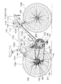
図1において、本発明の一実施形態を採用した自転車101は、ロードレーサであり、フロントフォーク98及びフロントフォーク98に固定されたハンドル部104を有するダイヤモンド形のフレーム102と、チェーン95やペダルPDが装着されたクランク96や前後のディレーラ97f,97rや前後のスプロケット群99f,99r等からなる駆動部105と、フロントフォーク98及びフレーム102後部に装着された前輪及び後輪106f,106rと、前後のブレーキ装置107f,107rとを備えている。
In FIG. 1, a
ハンドル部104は、図1に示すように、ハンドルステム111と、ハンドルステム111の上端で嵌合固定可能なハンドルバー組立体112とで構成されている。ハンドルステム111は、フロントフォーク98の上部に嵌合固定されている。
As shown in FIG. 1, the
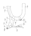
ハンドルバー組立体112は、図2から図4に示すように、ハンドルバー本体112aと、ハンドルバー本体112aの第1端側(自転車を後方から見て右側、すなわちライダーから見て右側)に取り付けられ、フロントディレーラ97fをシフトアップ方向に変速操作可能な第1変速操作部120と、ハンドルバー本体112aの第1端側に取り付けられ、リアディレーラ97rをシフトアップ方向に変速操作可能な第2変速操作部121と、を備えている。また、ハンドルバー組立体112は、第2端側(自転車の後方から見て左側、すなわちライダーから見て左側)に取り付けられ、フロントディレーラ97fをシフトダウン方向に変速操作可能な第3変速操作部122と、ハンドルバー本体112aの第2端側に取り付けられ、リアディレーラ97rをシフトダウン方向に変速操作可能な第4変速操作部123と、をさらに備えている。
As shown in FIGS. 2 to 4, the
ハンドルバー本体112aは、前方に突出して略U字状に湾曲する湾曲部112b,112cを有するドロップ型ハンドルバーであり、ハンドルバー組立体112は、ハンドルバー本体112aの両端側に設けられ、前後のブレーキ装置107f,107rを制動操作するための1対のブレーキ操作装置113f,113rをさらに備えている。前ブレーキ操作装置113fは、自転車101を後方から見てハンドルバー本体112aの右端側の湾曲部112bに配置され、後ブレーキ操作装置113rは、左端側の湾曲部112cに配置されている。ハンドルバー本体112aの中央部には、自転車の速度や走行距離を表示する速度表示部114が配置されている。
The handlebar
前後のブレーキ操作装置113f,113rは、図2から図5に示すように、ハンドルバー本体112aの1対の湾曲部112b,112c付近に各別に装着される前後のブレーキブラケット117f,117rと、ブレーキブラケット117f,117rに基端が揺動自在に連結された前後のブレーキレバー116f,116rとを有している。
As shown in FIGS. 2 to 5, the front and rear
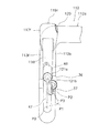
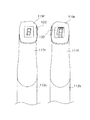
第1変速操作部120は、ハンドルバー本体112aの第1端側の湾曲部112b付近に装着されたブレーキブラケット117fの先端部内側面(ここで「内側」とはハンドルバーの中央部を向いた方向を示す)に取り付けられた、たとえば押しボタン型の第1スイッチ部材120aを有している。第2変速操作部121は、ブレーキレバー116fの後面に取り付けられブレーキレバー116fに近接して配置された、たとえばレバー型の第2スイッチ部材121a、及びハンドルバー本体112aの湾曲部112bに取り付けられたレバー型の第3スイッチ部材121bを有している。第3変速操作部122は、ハンドルバー本体112aの第2端側の湾曲部112c付近に装着されたブレーキブラケット117rの先端部内側面に取り付けられた、たとえば押しボタン型の第4スイッチ部材122aを有している。第4変速操作部123は、ブレーキレバー116rの後面に取り付けられた、たとえばレバー型の第5スイッチ部材123aを有している。第3スイッチ部材121bは、ハンドルバー本体112aの第1端側の末端112dとブレーキブラケット117fの取付位置との間でハンドルバー本体112aの湾曲部112bに配置されており、ブレーキ操作装置113fから離間した位置に配置されている。
The first speed
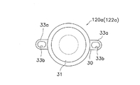
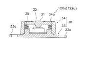
ボタン型の第1スイッチ部材120a(又は第4スイッチ部材122a)は、図6に示すように、ブレーキブラケット117f(又はブレーキブラケット117r)に固定される取付部30と、取付部30に移動自在に装着されたボタン型の操作部31と、操作部により押圧される、たとえばタクティールスイッチを用いたスイッチ部32とを有している。取付部30は、径方向に突出する2つの取付耳部33aを有する第1ケース部材33と、第1ケース部材33に固定された第2ケース部材34とを備えている。
As shown in FIG. 6, the button-type
取付耳部33aには、固定用のねじ部材が通過可能な長孔33bが形成されており、長孔33bにねじ部材を挿通してブレーキブラケット117f(又はブレーキブラケット117r)にねじ込むことにより第1スイッチ部材120a(又は第4スイッチ部材122a)がブレーキブラケット117f(又はブレーキブラケット117r)に固定される。この長孔33bを有する取付耳部33aは、たとえば、図2及び図3に示すように、後方にいくにつれて下がるように斜めに配置される。これにより、第1スイッチ部材120a(又は第4スイッチ部材122a)を斜めに位置調整可能に固定できる。位置調整可能な範囲は、たとえば3mm〜10mm程度が好ましい。これにより、ライダーの手の大きさや好みに合わせてシフトアップ用(又はシフトダウン用)の第1スイッチ部材120a(又は第4スイッチ部材122a)を配置できる。
A
第1ケース部材33と第2ケース部材34との間には、スイッチ部32を含む回路基板が収納可能な空間が形成されている。操作部31は、円板状で中心部が第2ケース部材34から僅かに突出する形状である。操作部31と第1ケース部材33との間には、たとえば4枚の皿ばね35が装着されている。これにより、操作部31は図7上方に付勢され、全体として第1スイッチ部材120a(又は第4スイッチ部材122a)が常閉スイッチとして構成される。第2ケース部材34には操作部31が露出する円形の開口34aが形成されている。開口34aの内径は操作部31の外形より小さい。これにより、操作部31は、第2ケース部材34により上方への移動が規制されている。
A space is formed between the
レバー型の第3スイッチ部材121bは、図8に示すように、ハンドルバー本体112aの湾曲部112bに固定される取付部36と、取付部36に設けられたレバー形状の操作部37とを有している。取付部36は、たとえば、ねじにより締め付け可能なバンド部38と、バンド部38と一体形成された第1ケース部材39と、第1ケース部材39に固定される第2ケース部材40とを備えている。バンド部38は、ハンドルバー本体112aの湾曲部112bに取付位置を調整可能に固定される。具体的には、湾曲部112bの湾曲方向や周方向に移動可能に固定される。第1ケース部材39と第2ケース部材40との間にはスイッチを構成する1つの接点が配置されている。
As shown in FIG. 8, the lever-type
また、第2ケース部材40には、揺動軸41が回動自在に装着されている。この揺動軸41の先端にレバー形状の操作部37が固定されている。揺動軸41の先端側外周面には、複数の凹部41aが周方向に間隔を隔てて形成されており、一つの凹部41aには、六角穴付き止めねじ42の先端が接触している。六角穴付き止めねじ42は、操作部37に揺動軸41の径方向外方からねじ込まれている。これにより、操作部37を揺動軸41の周方向の複数の取付位置のいずれかひとつに固定できる。すなわち、操作部37の周方向の取付位置を調整できる。操作部37は、図4に示すように、初期位置P2と、初期位置P2からハンドルバー本体112aの外側に揺動したオン位置P3との間で揺動する。なお、初期状態では、操作部37は、初期位置P2が湾曲部112bに沿って配置されるが、ライダーの体格や好みに合わせて操作部37の取付位置を調整できる。また、バンド部38により第3スイッチ部材121b全体の位置及び姿勢も変更できる。
In addition, a
レバー型の第2スイッチ部材121a(又は第5スイッチ部材123a)は、第3スイッチ部材121bと取付部46の構成と操作部47のレバー長さだけが異なる。固定部46は、バンドではなくねじ部材によりブレーキレバー116f(又は116r)の後面に固定される。ただし、第1スイッチ部材120aと同様に長孔により位置調整できるように構成してもよい。
The lever-type
操作部47は、図4に示すように、第3スイッチ部材121bの操作部37より長く、初期位置P0と、初期位置P0からハンドルバー本体112aの中央側(内側)に揺動したオン位置P1との間で揺動する。操作部47の取付姿勢は、第3スイッチ部材121bと同様に調整可能である。
As shown in FIG. 4, the
また、ブレーキブラケット117f,117rの先端部上面には、前後のディレーラ97f,97rの変速位置を、たとえば液晶表示する変速表示装置119r,119fが固定されている。
Further,
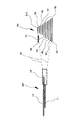
前スプロケット群99fは、図9に示すように、クランク軸の軸方向に並べて配置された歯数が異なる2枚のスプロケットF1,F2を有している。後スプロケット群99rは、後輪のハブ軸に沿った軸方向に並べて配置された歯数が異なる10枚のスプロケットR1〜R10を有している。ここでは、フロント側では軸方向内側にあるスプロケットF1が軸方向外側にあるスプロケットF2より歯数の少なく、歯数が最も多いトップ側(高速側)のスプロケットがスプロケットF2である。また、リア側では最も内側にあるスプロケットR1から順に歯数が少なくなり、最も外側にあるスプロケットR10が最も歯数が少なく、トップ側(高速側)のスプロケットがスプロケットR10である。前後のディレーラ97f,97rは、チェーン95を複数のスプロケットF1,F2,R1〜R10のいずれかに移動させて変速動作を行う。この変速操作は、第1〜第4変速操作部120〜123により行われる。
As shown in FIG. 9, the
フロントディレーラ(FD)97fは、複数(好ましくは2つ)の変速位置のいずれかにチェーン95を案内する電気制御可能な電動ディレーラである。フロントディレーラ97fは、図1に示すように、フレーム102のシートチューブ102aに固定された装着部材12fと、装着部材12fに対し接離する方向に移動可能なチェーンガイド14fと、装着部材12fとチェーンガイド14fとを連結する4点リンク機構16fと、4点リンク機構16fを介してチェーンガイド14fを駆動する電動駆動部18fと、電動駆動部18f及びその他の電気機器に電力を供給する電源装置20とを備えている。
The front derailleur (FD) 97f is an electrically controllable electric derailleur that guides the
電動駆動部18fは、図10に示すように、モータ125fと、モータ駆動部126fと、モータ駆動部126fを制御するフロント制御部127f(FD制御部)と、位置センサ128fと、を内部に有している。
As shown in FIG. 10, the
リアディレーラ(RD)97rは、図1に示すように、複数(好ましくは10個)の変速位置のいずれかにチェーン95を案内する電気制御可能な電動ディレーラである。リアディレーラ97rは、フレーム102のチェーンスティ102dの後部に固定された装着部材12rと、装着部材12rに対し相対的に移動可能なチェーンガイド14rと、装着部材12rとチェーンガイド14rとを連結する4点リンク機構16rと、4点リンク機構16rを介してチェーンガイド14rを駆動する電動駆動部18rとを備えている。
As shown in FIG. 1, the rear derailleur (RD) 97r is an electrically controllable electric derailleur that guides the
電動駆動部18rは、図4に示すように、モータ125r、モータ駆動部126r、モータ駆動部126rを制御するリア制御部127r(RD制御部)及び変速位置を検出する位置センサ128rを内部に有している。
As shown in FIG. 4, the
ここで、前後のモータ駆動部126f,126rは、モータ125f,125rの回転を減速する減速ユニット及びモータドライバを含むユニットである。前後の制御部127f,127rは、それぞれ記憶部や演算部等を有するマイクロコンピュータを含む制御回路を有しており、ソフトウェアにより変速操作部120〜123から出力される変速信号に応じてモータ駆動部126f,126rを各別に制御する。前後の位置センサ128f,128rは、各ディレーラ97f,97rの変速位置を検出するための、たとえばロータリエンコーダなどを用いたセンサである。電圧センサ135は、電源装置20の電源電圧を検出するセンサである。
Here, the front and rear
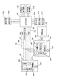
これらのディレーラ97f,97rの各部、変速操作部120〜123のスイッチ部材120a,121a,121b,122a,123a、表示制御部118及び前後の変速表示装置119f,119rには、図10に示すように、フロントディレーラ97fに装着された電源装置20から電力が供給される。具体的には、フロントディレーラ97fの電動駆動部18fには、電源線150及び接地線151を介して電源装置20から、たとえば直流6〜8.4ボルト程度の電源電圧Vの電力が供給される。また、電源駆動部18fから電源線152及び接地線153を介して、リアディレーラ97rの電動駆動部18r及び表示制御部118に電源電圧Vの電力が供給される。また、前後の変速表示装置119f,119r及び変速操作部120〜123のスイッチ部材120a,121a,121b,122a,123aには、表示制御部118を介して電源電圧Vの電力が供給される。また、前後の位置センサ128f,128rの変速位置信号FPOS,RPOSは、位置信号線154を介して表示制御部118に出力され、表示制御部118でそれらを表示信号にして前後の変速表示装置119f,119rで前後のディレーラ97f,97rの変速位置が表示される。位置信号線154には、電圧情報(VD:たとえば3段階の電圧情報)も出力される。また、変速操作部120〜123のスイッチ部材120a,121a,121b,122a,123aの操作に応じて出力される変速信号FDS,RDSは、表示制御部118を経由してそれぞれの変速信号線155,156を通って前後のディレーラ97f,97rに出力される。なお、変速信号RDSの変速信号線156は実際には、電動駆動部18fを経由して電動駆動部18rに接続される。したがって、フロントディレーラ97fの電動駆動部18fは、5芯の配線でたとえばダウンチューブ102cを経由して表示制御部118に接続され、電動駆動部18rは、4芯の配線でたとえばチェーンスティ102dを介して電動駆動部18fと接続される。したがって、電動駆動部18fにこれらの5芯の配線を一括して接続するコネクタを設けてもよい。
As shown in FIG. 10, each part of these
次に各制御部127f,127rによる概略の制御処理について説明する。
Next, a rough control process by the
フロント制御部127fでは、電源が投入されると、第1又は第3変速操作部120,122が操作され、第1スイッチ部材120a又は第4スイッチ部材122aがオンしたか否かを判断する。第1スイッチ部材120aが操作されるとフロントディレーラ97fをシフトアップ方向に動作させ、第4スイッチ部材122aが操作されるとフロントディレーラ97fをシフトダウン方向に動作させる。
When the power is turned on, the
リア制御部127rでは、電源が投入されると、第2又は第4変速操作部121,123が操作され、第2スイッチ部材121a及び第3スイッチ部材121b又は第5スイッチ部材123aがオンしたか否かを判断する。第2スイッチ部材121a又は第3スイッチ部材121bが操作されるとリアディレーラ97fをシフトアップ方向に動作させ、第5スイッチ部材123aが操作されるとリアディレーラ97fをシフトダウン方向に動作させる。
In the
このような4つの変速操作部120〜123を有する自転車101では、ブレーキブラケット117f,117rを握って走行する際には、手の親指でブレーキブラケット117f,117rの内側に配置された第1及び第3変速操作部120,122を操作し、フロントディレーラ97fのシフトアップ・シフトダウン操作を行える。また、手の人差し指又は中指の先端でブレーキレバー116f,116rの後面に配置された第2変速操作部121の第2スイッチ部材121a及び第4変速操作部123を操作し、リアディレーラ97fのシフトアップ・シフトダウン操作を行える。
In the
また、ハンドルバー本体112aの末端112d付近を握って高速走行する際には、第2変速操作部121の第3スイッチ部材121bを手の親指を用いて操作し、末端112d付近を握った状態でもリアディレーラ97rのシフトアップ操作を迅速かつ容易に行える。
Further, when the vehicle travels at a high speed while grasping the vicinity of the
ここでは、ハンドルバー本体112aの同じ側で前後のディレーラ97f,97rを変速操作できるので、例えばハンドルバー本体の一方側をシフトアップ操作とし、他方側をシフトダウン操作とすることができる。このため、比較的操作に不慣れな初心者でも変速操作部120〜123を誤操作しにくくなる。また、操作に習熟したライダーにとっても変速操作がさらに容易になるメリットがある。
Here, since the front and
また、第2変速操作部121の第3スイッチ部材121bがハンドルバー本体112aの末端112dに近い湾曲部に配置されるので、ゴール直前のスプリント中のようにハンドルバー本体112aの末端112d付近、すなわちドロップ型ハンドルバーの下側の握り部を握った状態でも第2変速操作部121を用いてシフトアップ操作することができる。このため、ゴール直前での加速動作を迅速かつ容易に行える。
In addition, since the
さらに、各変速操作部の位置及び/又は姿勢を調整可能にしたので、ライダーの体格や好みに合わせて各変速操作部を配置することができ、ライダーの体と自転車とのフィット感が向上する。 Furthermore, since the position and / or posture of each speed change operation unit can be adjusted, each speed change operation unit can be arranged according to the rider's physique and preference, and the fit between the rider's body and the bicycle is improved. .
<他の実施形態>
(a)前記実施形態では、第1及び第3変速操作部120,122に押しボタン型のスイッチ部材を用い、第2及び第4変速操作部121,123にレバー型のスイッチ部材を用いたが、本発明に用いるスイッチ部材はこれに限定されない。たとえば、スライド型のスイッチ部材やトグル型のスイッチ部材を用いてもよい。なお、スイッチ部材としては操作したときだけオンする常閉型のスイッチ部材が好ましい。
<Other embodiments>
(A) In the above embodiment, push button type switch members are used for the first and third speed
(b)前記実施形態では、第1及び第3変速操作部120,122をブレーキブラケット117f,117rの先端に配置したが、ブレーキブラケット117f,117rの基端側、好ましくは基端側内面に配置してもよい。この場合、ブレーキブラケット117f,117rの基端側を握ったときに変速操作部がオンしないようにスイッチ部材の操作部を周囲より僅かに凹ませて配置するのが好ましい。
(B) In the above-described embodiment, the first and third speed
(c)前記実施形態では、第3スイッチ部材121bを除いてブレーキ操作装置に変速操作部の各スイッチ部材を配置したが、本発明はこれに限定されない。各変速操作部は、ブレーキ操作装置及びハンドルバー本体のいずれに設けてもよい。
(C) In the above embodiment, each switch member of the speed change operation unit is arranged in the brake operation device except for the
30,36,46 取付部
31,37,47 操作部
97f フロントディレーラ
97r リアディレーラ
101 自転車
112 ハンドルバー組立体
112a ハンドルバー本体
112b,112c 湾曲部
112d 末端
113f,113r ブレーキ操作装置
116f,116r ブレーキレバー
117f,117r ブレーキブラケット
120〜123 第1〜第4変速操作部
30, 36, 46 Mounting
Claims (11)
ハンドルバー本体と、
前記ハンドルバー本体の第1端側に取り付けられ、電動制御可能なフロントディレーラを変速操作可能な第1変速操作部と、
前記ハンドルバー本体の前記第1端側に取り付けられ、電動制御可能なリアディレーラを変速操作可能な第2変速操作部と、
前記ハンドルバー本体の第2端側に取り付けられ、電動制御可能なフロントディレーラを変速操作可能な第3変速操作部と、
前記ハンドルバー本体の前記第2端側に取り付けられ、電動制御可能なリアディレーラを変速操作可能な第4変速操作部と、
を備えた自転車用ハンドルバー組立体。 A bicycle handlebar assembly,
The handlebar body,
A first shift operation unit attached to the first end side of the handlebar body and capable of shifting a front derailleur that can be electrically controlled;
A second speed change operation unit attached to the first end side of the handlebar body and capable of speed change operation of an electrically controlled rear derailleur;
A third speed change operation unit that is attached to the second end side of the handlebar body and is capable of speed change operation of the electrically controlled front derailleur;
A fourth shift operation unit attached to the second end side of the handlebar body and capable of shifting the electrically-controlled rear derailleur;
A handlebar assembly for a bicycle comprising:
前記第1および第2変速操作部は前記ブレーキ操作装置に取り付けられている、請求項1に記載の自転車用ハンドルバー組立体。 A brake operation device attached to the first end side of the handlebar body and capable of operating a brake;
2. The bicycle handlebar assembly according to claim 1, wherein the first and second speed change operation portions are attached to the brake operation device.
前記第1および第2変速操作部は前記ブレーキ操作装置から離間した位置に取り付けられている、請求項1に記載の自転車用ハンドルバー組立体。 A brake operation device attached to the first end side of the handlebar body and capable of operating a brake;
2. The bicycle handlebar assembly according to claim 1, wherein the first and second speed change operation portions are attached at positions separated from the brake operation device.
前記第1変速操作部および第2変速操作部のいずれか一方は前記ブレーキ操作装置に取り付けられ、他方は前記ブレーキ操作装置から離間した位置に取り付けられている、請求項1に記載の自転車用ハンドルバー組立体。 A brake operation device attached to the first end side of the handlebar body and capable of operating a brake;
2. The bicycle handle according to claim 1, wherein one of the first speed change operation unit and the second speed change operation unit is attached to the brake operation device, and the other is attached to a position separated from the brake operation device. Bar assembly.
前記第2変速操作部は、前記リアディレーラのシフトアップ方向の変速操作が可能である、請求項1から4のいずれか1項に記載の自転車用ハンドルバー組立体。 The first speed change operation unit is capable of a speed change operation in a shift-up direction of the front derailleur.
The bicycle handlebar assembly according to any one of claims 1 to 4, wherein the second speed change operation unit is capable of a speed change operation in the upshift direction of the rear derailleur.
前記第2変速操作部は、前記リアディレーラのシフトアップ方向の変速操作のみが可能である、請求項1から5のいずれか1項に記載の自転車用ハンドルバー組立体。 The first shift operation unit can only perform a shift operation in the upshift direction of the front derailleur,
The bicycle handlebar assembly according to any one of claims 1 to 5, wherein the second speed change operation unit is capable of only a speed change operation in the upshift direction of the rear derailleur.
前記第1変速操作部は前記ブレーキブラケットに設けられ、前記第2変速操作部は前記ブレーキレバーに近接して配置される、請求項2に記載の自転車用ハンドルバー組立体。 The brake operation device has a brake bracket attached to the handlebar body, and a brake lever whose base end is swingably connected to the brake bracket;
3. The bicycle handlebar assembly according to claim 2, wherein the first speed change operation portion is provided on the brake bracket, and the second speed change operation portion is disposed in proximity to the brake lever.
前記第4変速操作部は、前記リアディレーラのシフトダウン方向への変速操作が可能である、請求項1から7のいずれか1項に記載の自転車用ハンドルバー組立体。 The third speed change operation unit is capable of a speed change operation in a downshift direction of the front derailleur,
The bicycle handlebar assembly according to any one of claims 1 to 7, wherein the fourth shift operation unit is capable of shifting the rear derailleur in a shift-down direction.
ハンドルバー本体と、
前記ハンドルバー本体の第1端側に取り付けられたブレーキブラケットと、前記ブレーキブラケットに基端が揺動自在に連結されたブレーキレバーとを有するブレーキ操作装置と、
前記ハンドルバー本体の第1端側の末端と前記ブラケットの取付位置との間で前記ハンドルバー本体に取り付けられ、電動制御可能なリアディレーラのシフトアップ方向の変速操作のみが可能な変速操作部と、
を有する自転車用ハンドルバー組立体。 A bicycle handlebar assembly,
The handlebar body,
A brake operating device having a brake bracket attached to the first end side of the handlebar body, and a brake lever having a base end pivotably connected to the brake bracket;
A shift operation unit that is attached to the handlebar body between the end of the first end side of the handlebar body and the mounting position of the bracket, and that can only perform a shift operation in the upshift direction of a rear derailleur that can be electrically controlled;
A bicycle handlebar assembly.
前記変速操作部は前記湾曲部に取り付けられている、請求項9に記載の自転車用ハンドルバー組立体。 The handlebar body is a drop-type handlebar having a curved portion,
The gearshift operating part is attached to the curved portion, bicycle Ha nd Doruba assembly according to claim 9.
Priority Applications (11)
| Application Number | Priority Date | Filing Date | Title |
|---|---|---|---|
| JP2006279666A JP4366390B2 (en) | 2006-10-13 | 2006-10-13 | Bicycle handlebar assembly |
| TW096107887A TW200817233A (en) | 2006-10-13 | 2007-03-07 | Bicycle handlebar assembly and bicycle brake/derailleur operating unit |
| CN2009101330614A CN101537870B (en) | 2006-10-13 | 2007-04-30 | Bicycle handlebar assembly and bicycle brake operating device |
| CN2007101023829A CN101161542B (en) | 2006-10-13 | 2007-04-30 | Handlebar assembly for bicycle and brake operating device for bicycle |
| US11/776,728 US7874229B2 (en) | 2006-10-13 | 2007-07-12 | Bicycle handlebar assembly and bicycle brake/derailleur operating unit |
| EP08006451A EP1932754B1 (en) | 2006-10-13 | 2007-10-12 | Bicycle handlebar assembly and bicycle brake operating device |
| EP07020073A EP1911668B1 (en) | 2006-10-13 | 2007-10-12 | Bicycle handlebar assembly and bicycle brake operating device |
| DE602007007417T DE602007007417D1 (en) | 2006-10-13 | 2007-10-12 | Bicycle Handlebar Arrangement and Bicycle Brake Actuator |
| DE602007004420T DE602007004420D1 (en) | 2006-10-13 | 2007-10-12 | Handlebar assembly and brake actuator for a bicycle |
| EP08006452A EP1935778B1 (en) | 2006-10-13 | 2007-10-12 | Bicycle handlebar assembly and bicycle brake operating device |
| DE602007004177T DE602007004177D1 (en) | 2006-10-13 | 2007-10-12 | Handlebar assembly and brake actuator for a bicycle |
Applications Claiming Priority (1)
| Application Number | Priority Date | Filing Date | Title |
|---|---|---|---|
| JP2006279666A JP4366390B2 (en) | 2006-10-13 | 2006-10-13 | Bicycle handlebar assembly |
Publications (2)
| Publication Number | Publication Date |
|---|---|
| JP2008094291A JP2008094291A (en) | 2008-04-24 |
| JP4366390B2 true JP4366390B2 (en) | 2009-11-18 |
Family
ID=38692034
Family Applications (1)
| Application Number | Title | Priority Date | Filing Date |
|---|---|---|---|
| JP2006279666A Expired - Fee Related JP4366390B2 (en) | 2006-10-13 | 2006-10-13 | Bicycle handlebar assembly |
Country Status (6)
| Country | Link |
|---|---|
| US (1) | US7874229B2 (en) |
| EP (3) | EP1932754B1 (en) |
| JP (1) | JP4366390B2 (en) |
| CN (2) | CN101161542B (en) |
| DE (3) | DE602007004177D1 (en) |
| TW (1) | TW200817233A (en) |
Families Citing this family (40)
| Publication number | Priority date | Publication date | Assignee | Title |
|---|---|---|---|---|
| US8438946B2 (en) * | 2008-06-06 | 2013-05-14 | Societe De Velo En Libre-Service | Handlebar for a bicycle |
| US8286529B2 (en) * | 2009-01-26 | 2012-10-16 | Shimano Inc. | Bicycle control device |
| US9394031B2 (en) * | 2009-07-16 | 2016-07-19 | Shimano Inc. | Bar end electric shifter for bicycle |
| USD634378S1 (en) * | 2009-11-10 | 2011-03-15 | Saris Cycling Group, Inc. | Handlebar for an exercise cycle |
| US9327792B2 (en) | 2011-01-28 | 2016-05-03 | Paha Designs, Llc | Gear transmission and derailleur system |
| US10207772B2 (en) | 2011-01-28 | 2019-02-19 | Paha Designs, Llc | Gear transmission and derailleur system |
| US9033833B2 (en) | 2011-01-28 | 2015-05-19 | Paha Designs, Llc | Gear transmission and derailleur system |
| US10479438B2 (en) * | 2011-03-31 | 2019-11-19 | Shimano Inc. | Bicycle brake and shift operating device |
| US8955862B1 (en) * | 2012-05-15 | 2015-02-17 | MonoMano, Inc. | Cycling control system |
| US9090303B2 (en) | 2012-05-18 | 2015-07-28 | Shimano Inc. | Bicycle control device |
| US10053181B2 (en) | 2012-05-30 | 2018-08-21 | Shimano Inc. | Bicycle shift operating device |
| US8723659B2 (en) | 2012-07-10 | 2014-05-13 | Shimano Inc. | Bicycle gear shift indicator |
| US9056651B2 (en) | 2012-08-27 | 2015-06-16 | Shimano Inc. | Bicycle control device |
| US9090304B2 (en) * | 2012-08-27 | 2015-07-28 | Shimano Inc. | Bicycle control device |
| US8878658B2 (en) | 2012-09-12 | 2014-11-04 | Shimano Inc. | Gear shift notification apparatus having a preselected notification pattern |
| US10061342B2 (en) * | 2013-01-31 | 2018-08-28 | Shimano Inc. | Bicycle operating device |
| JP5753865B2 (en) * | 2013-02-28 | 2015-07-22 | 東芝テック株式会社 | Assist robot and its control program |
| US8958962B2 (en) | 2013-04-05 | 2015-02-17 | Shimano Inc. | Electric shift operating device |
| JP2014231330A (en) * | 2013-05-30 | 2014-12-11 | 株式会社シマノ | Operating device |
| ITMI20131912A1 (en) * | 2013-11-19 | 2015-05-20 | Campagnolo Srl | DEVICE AND CONTROL SYSTEM OF AN ELECTRONIC BICYCLE SYSTEM AND ELECTRONIC BICYCLE SYSTEM USING THE SAME |
| US20150285376A1 (en) * | 2014-04-03 | 2015-10-08 | Colleen M. Hageman | Bicycle gear shift indicator and display |
| JP2016020124A (en) * | 2014-07-14 | 2016-02-04 | 株式会社シマノ | Control device for bicycle |
| US10293884B2 (en) | 2015-08-19 | 2019-05-21 | Sram, Llc | Bicycle electrical control device and system |
| US10486658B2 (en) | 2016-04-21 | 2019-11-26 | Shimano Inc. | Bicycle operating device |
| US10759489B2 (en) | 2016-04-21 | 2020-09-01 | Shimano Inc. | Bicycle operating device |
| US10858063B2 (en) * | 2016-04-21 | 2020-12-08 | Shimano Inc. | Bicycle operating device |
| US10843763B2 (en) | 2016-04-21 | 2020-11-24 | Shimano Inc. | Bicycle operating device |
| US10604206B2 (en) | 2016-04-21 | 2020-03-31 | Shimano Inc. | Bicycle operating device |
| US10407121B2 (en) | 2016-04-21 | 2019-09-10 | Shimano Inc. | Bicycle operating device |
| US11027709B2 (en) | 2016-04-21 | 2021-06-08 | Shimano Inc. | Bicycle operating device |
| US10562584B2 (en) | 2016-11-24 | 2020-02-18 | Shimano Inc. | Bicycle operating device |
| TWI694945B (en) * | 2016-08-26 | 2020-06-01 | 日商島野股份有限公司 | Bicycle operating device |
| CN107839829A (en) * | 2017-11-02 | 2018-03-27 | 苏州达方电子有限公司 | Car handle structure |
| JP6921724B2 (en) * | 2017-11-30 | 2021-08-18 | 株式会社シマノ | Shift control device and electric shift system |
| IT201800006887A1 (en) * | 2018-07-03 | 2020-01-03 | Control device for a bicycle and an electronic device for a bicycle comprising such control device | |
| US10994798B2 (en) * | 2018-08-30 | 2021-05-04 | Shimano Inc. | Operating device and base member |
| US11554834B2 (en) * | 2019-07-29 | 2023-01-17 | Shimano Inc. | Operating system for human-powered vehicle |
| US12084146B2 (en) * | 2019-09-05 | 2024-09-10 | Shimano Inc. | Master communication apparatus, slave communication apparatus, and wireless communication apparatus |
| JP7324658B2 (en) | 2019-08-29 | 2023-08-10 | 株式会社シマノ | ELECTRONIC DEVICE RELATED TO OPERATING DEVICE FOR MANPOWERED VEHICLE, AND CONTROL METHOD IN ELECTRONIC DEVICE RELATED TO OPERATING DEVICE FOR MANPOWERED VEHICLE |
| US10988209B1 (en) * | 2020-03-11 | 2021-04-27 | Sram, Llc | Bicycle control system |
Family Cites Families (26)
| Publication number | Priority date | Publication date | Assignee | Title |
|---|---|---|---|---|
| US4270402A (en) * | 1977-10-05 | 1981-06-02 | Shimano Industrial Company, Limited | Speed changing device for a bicycle |
| FR2654698A1 (en) | 1989-11-17 | 1991-05-24 | Sachs Ind Sa | FUNCTIONAL AND ERGONOMIC STEERING BODY WITH INTEGRATED CONTROL CENTER FOR CYCLE. |
| DE4022473C2 (en) * | 1990-07-14 | 1994-01-20 | Rolf Dr Meissner | Derailleur for a bicycle |
| FR2687977B1 (en) * | 1992-02-27 | 1994-04-22 | Bg Innovation | DEVICES ALLOWING THE CHANGES OF SPEEDS ON BICYCLES. |
| IT1261090B (en) * | 1993-07-08 | 1996-05-08 | Antonio Romano | MOTORIZED SPEED CHANGE UNIT FOR BICYCLES. |
| JP3470820B2 (en) * | 1993-10-06 | 2003-11-25 | 株式会社シマノ | Bicycle transmission |
| US5493933A (en) * | 1994-01-10 | 1996-02-27 | Kelly; Christopher J. | One piece shift lever mount adapter for a bicycle |
| IT1280987B1 (en) | 1995-10-19 | 1998-02-11 | Campagnolo Srl | "MOUNTAIN-BIKE" TYPE BICYCLE HANDLEBAR OR SIMILAR, WITH DISPLAY DEVICE ASSOCIATED WITH AN ELECTRONIC GEAR CONTROL. |
| US5850761A (en) | 1996-12-17 | 1998-12-22 | Shimano Inc. | Brake operating device for handle bar and bar ends |
| JP3321045B2 (en) * | 1996-12-20 | 2002-09-03 | 株式会社シマノ | Bicycle electrical operating device |
| JP3510442B2 (en) * | 1997-01-14 | 2004-03-29 | 株式会社シマノ | Bicycle electric shifting mechanism |
| US5881602A (en) * | 1997-03-20 | 1999-03-16 | Cirami; Salvatore | Gearshift for dual derailleur bicycle |
| JP3474080B2 (en) * | 1997-05-16 | 2003-12-08 | 株式会社シマノ | Bicycle switch |
| IT1320405B1 (en) * | 2000-06-06 | 2003-11-26 | Campagnolo Srl | ELECTRIC CONTROL DEVICE FOR A MOTORIZED FRONT DERAILLEUR. |
| US6367833B1 (en) | 2000-09-13 | 2002-04-09 | Shimano, Inc. | Automatic shifting control device for a bicycle |
| EP1225123B1 (en) | 2001-01-23 | 2006-06-14 | Samuel Y.T. Strong | Handlebar accelerator for an electrical bicycle |
| US6546827B2 (en) * | 2001-03-28 | 2003-04-15 | Shimano Inc. | Bicycle handlebar |
| US6523772B2 (en) | 2001-05-29 | 2003-02-25 | Shimano Inc. | Electric device with cord retainer for bicycle |
| ITTO20010555A1 (en) * | 2001-06-08 | 2002-12-08 | Campagnolo Srl | ELECTRIC CONTROL DEVICE FOR A MOTORIZED FRONT DERAILLEUR FOR BICYCLES. |
| US7204169B2 (en) * | 2003-04-10 | 2007-04-17 | Ross Mitchell | Gear shifting mechanism |
| EP1473220A1 (en) | 2003-04-30 | 2004-11-03 | Campagnolo Srl | Control device for a bicycle derailleur |
| ATE312750T1 (en) * | 2003-07-24 | 2005-12-15 | Campagnolo Srl | METHOD FOR SHIFTING A BICYCLE TRANSMISSION WITH ELECTRICAL AUXILIARY DRIVE AND SHIFTING DEVICE |
| US6991081B2 (en) * | 2003-11-26 | 2006-01-31 | Shimano Inc. | Shift and break control device |
| JP2005238873A (en) | 2004-02-24 | 2005-09-08 | Shimano Inc | Bicycle speed change control device and front derailleur control method |
| US7350436B2 (en) | 2004-03-29 | 2008-04-01 | Shimano, Inc. | Electrical bicycle shift control device |
| JP2005297712A (en) * | 2004-04-09 | 2005-10-27 | Shimano Inc | Speed-change control device for bicycle and control method |
-
2006
- 2006-10-13 JP JP2006279666A patent/JP4366390B2/en not_active Expired - Fee Related
-
2007
- 2007-03-07 TW TW096107887A patent/TW200817233A/en unknown
- 2007-04-30 CN CN2007101023829A patent/CN101161542B/en active Active
- 2007-04-30 CN CN2009101330614A patent/CN101537870B/en active Active
- 2007-07-12 US US11/776,728 patent/US7874229B2/en active Active
- 2007-10-12 EP EP08006451A patent/EP1932754B1/en active Active
- 2007-10-12 EP EP08006452A patent/EP1935778B1/en active Active
- 2007-10-12 EP EP07020073A patent/EP1911668B1/en active Active
- 2007-10-12 DE DE602007004177T patent/DE602007004177D1/en active Active
- 2007-10-12 DE DE602007007417T patent/DE602007007417D1/en active Active
- 2007-10-12 DE DE602007004420T patent/DE602007004420D1/en active Active
Also Published As
| Publication number | Publication date |
|---|---|
| US20080087131A1 (en) | 2008-04-17 |
| EP1932754B1 (en) | 2010-01-20 |
| TWI331112B (en) | 2010-10-01 |
| DE602007007417D1 (en) | 2010-08-12 |
| DE602007004420D1 (en) | 2010-03-11 |
| EP1935778A3 (en) | 2008-07-02 |
| EP1911668B1 (en) | 2010-06-30 |
| US7874229B2 (en) | 2011-01-25 |
| DE602007004177D1 (en) | 2010-02-25 |
| EP1935778A2 (en) | 2008-06-25 |
| CN101537870B (en) | 2013-06-12 |
| EP1932754A3 (en) | 2008-07-02 |
| CN101161542B (en) | 2010-06-02 |
| CN101537870A (en) | 2009-09-23 |
| TW200817233A (en) | 2008-04-16 |
| EP1911668A1 (en) | 2008-04-16 |
| EP1932754A2 (en) | 2008-06-18 |
| EP1935778B1 (en) | 2010-01-06 |
| CN101161542A (en) | 2008-04-16 |
| JP2008094291A (en) | 2008-04-24 |
Similar Documents
| Publication | Publication Date | Title |
|---|---|---|
| JP4366390B2 (en) | Bicycle handlebar assembly | |
| JP4191757B2 (en) | Bicycle shift control device | |
| JP4395504B2 (en) | Bicycle shifting operation device | |
| CN101219698B (en) | Bicycle brake and shift operating device | |
| EP2546128B1 (en) | Bicycle shift operating device | |
| EP2020371B1 (en) | Bicycle control device | |
| US10479438B2 (en) | Bicycle brake and shift operating device | |
| US9463841B2 (en) | Bicycle brake and shift operating device | |
| JP4266986B2 (en) | Bicycle display device and bicycle control device | |
| EP2030890B1 (en) | Bicycle component with position sensing |
Legal Events
| Date | Code | Title | Description |
|---|---|---|---|
| A977 | Report on retrieval |
Free format text: JAPANESE INTERMEDIATE CODE: A971007 Effective date: 20080828 |
|
| A131 | Notification of reasons for refusal |
Free format text: JAPANESE INTERMEDIATE CODE: A131 Effective date: 20080902 |
|
| A521 | Request for written amendment filed |
Free format text: JAPANESE INTERMEDIATE CODE: A523 Effective date: 20081022 |
|
| RD02 | Notification of acceptance of power of attorney |
Free format text: JAPANESE INTERMEDIATE CODE: A7422 Effective date: 20081022 |
|
| A131 | Notification of reasons for refusal |
Free format text: JAPANESE INTERMEDIATE CODE: A131 Effective date: 20090217 |
|
| A521 | Request for written amendment filed |
Free format text: JAPANESE INTERMEDIATE CODE: A523 Effective date: 20090225 |
|
| TRDD | Decision of grant or rejection written | ||
| A01 | Written decision to grant a patent or to grant a registration (utility model) |
Free format text: JAPANESE INTERMEDIATE CODE: A01 Effective date: 20090811 |
|
| A01 | Written decision to grant a patent or to grant a registration (utility model) |
Free format text: JAPANESE INTERMEDIATE CODE: A01 |
|
| A61 | First payment of annual fees (during grant procedure) |
Free format text: JAPANESE INTERMEDIATE CODE: A61 Effective date: 20090824 |
|
| FPAY | Renewal fee payment (event date is renewal date of database) |
Free format text: PAYMENT UNTIL: 20120828 Year of fee payment: 3 |
|
| R150 | Certificate of patent or registration of utility model |
Ref document number: 4366390 Country of ref document: JP Free format text: JAPANESE INTERMEDIATE CODE: R150 Free format text: JAPANESE INTERMEDIATE CODE: R150 |
|
| FPAY | Renewal fee payment (event date is renewal date of database) |
Free format text: PAYMENT UNTIL: 20120828 Year of fee payment: 3 |
|
| FPAY | Renewal fee payment (event date is renewal date of database) |
Free format text: PAYMENT UNTIL: 20130828 Year of fee payment: 4 |
|
| R250 | Receipt of annual fees |
Free format text: JAPANESE INTERMEDIATE CODE: R250 |
|
| R250 | Receipt of annual fees |
Free format text: JAPANESE INTERMEDIATE CODE: R250 |
|
| R250 | Receipt of annual fees |
Free format text: JAPANESE INTERMEDIATE CODE: R250 |
|
| R250 | Receipt of annual fees |
Free format text: JAPANESE INTERMEDIATE CODE: R250 |
|
| R250 | Receipt of annual fees |
Free format text: JAPANESE INTERMEDIATE CODE: R250 |
|
| R250 | Receipt of annual fees |
Free format text: JAPANESE INTERMEDIATE CODE: R250 |
|
| R250 | Receipt of annual fees |
Free format text: JAPANESE INTERMEDIATE CODE: R250 |
|
| R250 | Receipt of annual fees |
Free format text: JAPANESE INTERMEDIATE CODE: R250 |
|
| R250 | Receipt of annual fees |
Free format text: JAPANESE INTERMEDIATE CODE: R250 |
|
| LAPS | Cancellation because of no payment of annual fees |