JP2005297712A - Speed-change control device for bicycle and control method - Google Patents
Speed-change control device for bicycle and control method Download PDFInfo
- Publication number
- JP2005297712A JP2005297712A JP2004115582A JP2004115582A JP2005297712A JP 2005297712 A JP2005297712 A JP 2005297712A JP 2004115582 A JP2004115582 A JP 2004115582A JP 2004115582 A JP2004115582 A JP 2004115582A JP 2005297712 A JP2005297712 A JP 2005297712A
- Authority
- JP
- Japan
- Prior art keywords
- switch
- shift
- turned
- operation unit
- bicycle
- Prior art date
- Legal status (The legal status is an assumption and is not a legal conclusion. Google has not performed a legal analysis and makes no representation as to the accuracy of the status listed.)
- Pending
Links
- 238000000034 method Methods 0.000 title claims description 72
- 230000005540 biological transmission Effects 0.000 claims description 74
- 230000007935 neutral effect Effects 0.000 claims description 8
- 239000004973 liquid crystal related substance Substances 0.000 description 6
- 238000001514 detection method Methods 0.000 description 2
- 241000270281 Coluber constrictor Species 0.000 description 1
- 230000007423 decrease Effects 0.000 description 1
- 238000010586 diagram Methods 0.000 description 1
- OQZCSNDVOWYALR-UHFFFAOYSA-N flurochloridone Chemical compound FC(F)(F)C1=CC=CC(N2C(C(Cl)C(CCl)C2)=O)=C1 OQZCSNDVOWYALR-UHFFFAOYSA-N 0.000 description 1
Images
Classifications
-
- B—PERFORMING OPERATIONS; TRANSPORTING
- B62—LAND VEHICLES FOR TRAVELLING OTHERWISE THAN ON RAILS
- B62M—RIDER PROPULSION OF WHEELED VEHICLES OR SLEDGES; POWERED PROPULSION OF SLEDGES OR SINGLE-TRACK CYCLES; TRANSMISSIONS SPECIALLY ADAPTED FOR SUCH VEHICLES
- B62M25/00—Actuators for gearing speed-change mechanisms specially adapted for cycles
- B62M25/08—Actuators for gearing speed-change mechanisms specially adapted for cycles with electrical or fluid transmitting systems
-
- Y—GENERAL TAGGING OF NEW TECHNOLOGICAL DEVELOPMENTS; GENERAL TAGGING OF CROSS-SECTIONAL TECHNOLOGIES SPANNING OVER SEVERAL SECTIONS OF THE IPC; TECHNICAL SUBJECTS COVERED BY FORMER USPC CROSS-REFERENCE ART COLLECTIONS [XRACs] AND DIGESTS
- Y10—TECHNICAL SUBJECTS COVERED BY FORMER USPC
- Y10T—TECHNICAL SUBJECTS COVERED BY FORMER US CLASSIFICATION
- Y10T74/00—Machine element or mechanism
- Y10T74/20—Control lever and linkage systems
- Y10T74/20012—Multiple controlled elements
- Y10T74/20018—Transmission control
- Y10T74/2003—Electrical actuator
-
- Y—GENERAL TAGGING OF NEW TECHNOLOGICAL DEVELOPMENTS; GENERAL TAGGING OF CROSS-SECTIONAL TECHNOLOGIES SPANNING OVER SEVERAL SECTIONS OF THE IPC; TECHNICAL SUBJECTS COVERED BY FORMER USPC CROSS-REFERENCE ART COLLECTIONS [XRACs] AND DIGESTS
- Y10—TECHNICAL SUBJECTS COVERED BY FORMER USPC
- Y10T—TECHNICAL SUBJECTS COVERED BY FORMER US CLASSIFICATION
- Y10T74/00—Machine element or mechanism
- Y10T74/20—Control lever and linkage systems
- Y10T74/20396—Hand operated
- Y10T74/20402—Flexible transmitter [e.g., Bowden cable]
- Y10T74/2042—Flexible transmitter [e.g., Bowden cable] and hand operator
- Y10T74/20438—Single rotatable lever [e.g., for bicycle brake or derailleur]
Landscapes
- Engineering & Computer Science (AREA)
- Chemical & Material Sciences (AREA)
- Combustion & Propulsion (AREA)
- Transportation (AREA)
- Mechanical Engineering (AREA)
- Control Of Transmission Device (AREA)
- Steering Devices For Bicycles And Motorcycles (AREA)
Abstract
Description
本発明は、変速制御装置、特に、複数の変速段を有する自転車用変速装置を制御する自転車用変速制御装置及び制御方法に関する。 The present invention relates to a transmission control device, and more particularly to a bicycle transmission control device and a control method for controlling a bicycle transmission device having a plurality of shift speeds.
複数の変速段を有する自転車用の変速装置としてフロントディレーラとリアディレーラとを有する外装変速装置や内装変速ハブを有する内装変速装置が知られている。 As a bicycle transmission having a plurality of shift speeds, an exterior transmission having a front derailleur and a rear derailleur and an internal transmission having an internal transmission hub are known.
外装変速装置では、クランク軸に軸方向に並べて装着された複数のフロントスプロケットと後輪ハブ軸に軸方向に並べて装着された複数のリアスプロケットのいずれかにフロントディレーラ及びリアディレーラによりチェーンを移動させて変速を行う。このような外装変速装置において、モータなどのアクチュエータによりチェーンを移動させることができる電気制御可能なディレーラ及びその制御装置が従来知られている(特許文献1参照)。 In the exterior transmission, the chain is moved by the front derailleur and the rear derailleur to one of the plurality of front sprockets mounted side by side on the crankshaft and the plurality of rear sprockets mounted side by side on the rear wheel hub shaft. Change gears. In such an exterior speed change device, an electrically controllable derailleur that can move a chain by an actuator such as a motor and a control device therefor have been conventionally known (see Patent Document 1).
また、内装変速装置では、遊星歯車機構を有する内装変速ハブにより変速率が異なる複数の動力伝達経路を構成し、いずれかひとつの動力伝達経路を選択して変速を行う。このような内装変速装置において、モータにより動力伝達経路を切換可能な内装変速ハブ及びその制御装置が従来知られている(特許文献2参照)。 In the internal transmission, a plurality of power transmission paths having different gear ratios are configured by an internal transmission hub having a planetary gear mechanism, and a shift is performed by selecting any one of the power transmission paths. In such an internal transmission, an internal transmission hub capable of switching a power transmission path by a motor and a control device therefor are conventionally known (see Patent Document 2).
従来の電気制御可能な変速装置を制御する変速制御装置は、ハンドルバーの両側又は片側に設けられた変速用の変速操作部を有している。たとえば、外装変速装置の制御装置では、ハンドルバーの右側にはリアディレーラ用の変速操作部が設けられ、左側にはフロントディレーラ用の変速操作部が設けられている。各変速操作部は、上下に並べて配置されたシフトアップ用及びシフトダウン用のスイッチを有している。また、内装変速装置の制御装置では、ハンドルバーの右側に左右に並べて配置されたシフトアップ用及びシフトダウン用のスイッチを有している。そして、何れの場合も、シフトアップ用及びシフトダウン用のスイッチを操作すると、1段ずつシフトアップ及びシフトダウンをそれぞれ行うように変速装置を制御する。
前記従来の構成では、各変速操作部において、シフトダウン用及びシフトアップ用のスイッチは上下又は左右に並べて配置されており、その配置は固定されている。しかし、ライダーによっては2つのスイッチを逆の配置にした方が好ましいことがある。もし、前者の従来の変速操作部でスイッチ操作を変更するためにスイッチの配置を逆にしようとすると、変速操作部を上下逆に装着したり、配線を変更したりするなどの煩わしい作業が必要になる。また、後者の従来の変速操作部では、配線を変更するという煩わしい作業が発生する。このため、従来の変速制御装置では、シフトアップ及びシフトダウンのスイッチ操作を容易に変更できない。 In the conventional configuration, in each shift operation unit, the downshift and upshift switches are arranged side by side in the vertical and horizontal directions, and the arrangement is fixed. However, some riders may prefer to place the two switches in the opposite orientation. If you try to reverse the switch layout in order to change the switch operation with the former conventional speed change operation part, troublesome work such as mounting the speed change operation part upside down or changing the wiring is required become. Further, in the latter conventional speed change operation unit, troublesome work of changing the wiring occurs. For this reason, in the conventional shift control device, the switch operation of the upshift and the downshift cannot be easily changed.
本発明の課題は、複数の変速段を有する自転車用変速装置を制御する自転車変速制御装置において、シフトアップ及びシフトダウンのスイッチ操作を容易に変更できるようにすることにある。 An object of the present invention is to make it possible to easily change the shift-up and shift-down switch operations in a bicycle transmission control device that controls a bicycle transmission device having a plurality of gear positions.
発明1に係る自転車用変速制御装置は、複数の変速段を有する自転車用変速装置を制御する装置であって、第1スイッチと、第2スイッチと、スイッチ関連付け変更部と、変速制御部とを備えている。第2スイッチは、第1スイッチと異なる位置に配置されるスイッチである。スイッチ関連付け変更部は、第1スイッチ及び第2スイッチと、自転車用変速装置のシフトアップ動作及びシフトダウン動作との関連付けを変更可能なものである。変速制御部は、第1及び第2スイッチのうち、シフトアップ動作に関連づけられたスイッチにより自転車用変速装置をシフトアップし、シフトダウン動作に関連づけられたスイッチにより自転車用変速装置をシフトダウンするものである。 A bicycle transmission control device according to a first aspect of the invention is a device that controls a bicycle transmission device having a plurality of shift stages, and includes a first switch, a second switch, a switch association changing unit, and a transmission control unit. I have. The second switch is a switch arranged at a position different from the first switch. The switch association changing unit is capable of changing the association between the first switch and the second switch and the upshifting operation and the downshifting operation of the bicycle transmission. The shift control unit shifts up the bicycle transmission with the switch associated with the upshifting operation and shifts down the bicycle transmission with the switch associated with the downshifting operation, among the first and second switches. It is.
この自転車用変速制御装置では、第1及び第2スイッチのうちシフトアップ動作に関連付けられたスイッチによりシフトアップ動作が行われ、シフトダウン動作に関連付けられたスイッチによりシフトダウン動作が行われる。この第1及び第2スイッチとシフトアップ動作及びシフトダウン動作との関連づけがスイッチ関連付け変更部で関連付けられるとともに変更可能である。たとえば、最初に第1スイッチがシフトアップ動作に、第2スイッチがシフトダウン動作に関連付けられていたとしても、第1スイッチをシフトダウン動作に関連付けなおし、第2スイッチをシフトアップ動作に関連付けなおすことができる。ここでは、第1及び第2スイッチとシフトアップ動作及びシフトダウン動作との関連づけを変更可能であるので、シフトアップ及びシフトダウンのスイッチ操作を容易に変更できるようになる。 In this bicycle shift control device, the shift-up operation is performed by the switch associated with the shift-up operation among the first and second switches, and the shift-down operation is performed by the switch associated with the shift-down operation. The association of the first and second switches with the upshifting operation and the downshifting operation is associated with the switch association changing unit and can be changed. For example, even if the first switch is initially associated with the upshift operation and the second switch is associated with the downshift operation, the first switch is reassociated with the downshift operation and the second switch is reassociated with the upshift operation. Can do. Here, the association between the first and second switches and the shift-up operation and the shift-down operation can be changed, so that the switch operation of the shift-up and shift-down can be easily changed.
発明2に係る自転車用変速制御装置は、発明1に記載の装置において、第1位置と第1位置と異なる第2位置との間で移動自在であり、第1位置に移動したとき又は移動過程で第1スイッチがオンし、第2位置に移動したとき又は移動過程で第2スイッチがオンする操作部をさらに備え、変速制御部は、第1及び第2スイッチのうち、シフトアップ動作に関連づけられたスイッチがオンするように操作部が操作されると、自転車用変速装置をシフトアップし、シフトダウン動作に関連づけられたスイッチがオンするように操作部が操作されると、自転車用変速装置をシフトダウンする。この場合には、第1及び第2スイッチを直接操作するのではなく、操作部の異なる位置への移動により第1及び第2スイッチをオンできるので、1つの操作部の操作でシフトアップ操作とシフトダウン操作を行え、変速操作が容易になる。 A bicycle shift control device according to a second aspect of the present invention is the device according to the first aspect, wherein the bicycle shift control device is movable between a first position and a second position different from the first position, and when moved to the first position or in a moving process. The operation unit further includes an operation unit that turns on the second switch when the first switch is turned on and moved to the second position, and the shift control unit relates to the shift-up operation of the first and second switches. When the operation unit is operated so that the switch is turned on, the bicycle transmission is shifted up, and when the operation unit is operated so that the switch associated with the shift-down operation is turned on, the bicycle transmission is Downshift. In this case, instead of directly operating the first and second switches, the first and second switches can be turned on by moving the operation unit to a different position. Shift-down operation can be performed, and shifting operation becomes easy.
発明3に係る自転車用変速制御装置は、発明2に記載の装置において、操作部は、第1位置と第2位置との間に配置される中立位置を有する。この場合には、2つの位置の間に中立位置が設けられているので、中立位置から2つの位置のいずれかに操作部を移動させることにより変速操作を行え、変速操作がより容易になる。 A bicycle shift control device according to a third aspect is the device according to the second aspect, wherein the operating portion has a neutral position disposed between the first position and the second position. In this case, since the neutral position is provided between the two positions, the shift operation can be performed by moving the operation unit from the neutral position to one of the two positions, and the shift operation becomes easier.
発明4に係る自転車用変速制御装置は、発明1から3のいずれかに記載の装置において、スイッチ関連付け変更部は、スイッチ関連付け操作部を有し、スイッチ関連付け操作部が操作された状態で第1及び第2スイッチのいずれかをオンさせると、オンしたスイッチをシフトアップスイッチとシフトダウンスイッチのいずれか一方として関連付け、オンしなかったスイッチをいずれか他方として関連付ける。この場合には、関連付け用のスイッチ関連付け操作部を操作して第1及び第2スイッチのいずれかをオンするだけで2つのスイッチの関連づけを一度に変更できるので、関連づけの変更操作が容易である。 A bicycle shift control device according to a fourth aspect of the present invention is the device according to any one of the first to third aspects, wherein the switch association changing unit has a switch association operation unit, and the switch association operation unit is operated in the first state. When any one of the second switch and the second switch is turned on, the turned-on switch is associated as one of the shift-up switch and the shift-down switch, and the switch that has not been turned on is associated as the other. In this case, since the association between the two switches can be changed at a time only by turning on one of the first and second switches by operating the switch association operation unit for association, the association changing operation is easy. .
発明5に係る自転車用変速制御装置は、発明2又は3に記載の装置において、スイッチ関連付け変更部は、スイッチ関連付け操作部を有し、スイッチ関連付け操作部が操作された状態で操作部が第1及び第2位置のいずれかに操作されると、操作された位置でオンするスイッチをシフトアップスイッチとシフトダウンスイッチのいずれか一方として関連付け、オンしなかったスイッチをいずれか他方として関連付ける。この場合には、関連付け用のスイッチ関連付け操作部を操作して操作部をいずれかの位置に移動させるだけで関連づけを変更できるので、関連づけの変更操作がより容易である。 A bicycle shift control device according to a fifth aspect of the present invention is the device according to the second or third aspect, wherein the switch association changing unit has a switch association operation unit, and the operation unit is the first in a state where the switch association operation unit is operated. When the switch is operated to one of the second positions, the switch that is turned on at the operated position is associated as one of the shift-up switch and the shift-down switch, and the switch that is not turned on is associated as the other. In this case, since the association can be changed simply by operating the switch association operation unit for association and moving the operation unit to any position, the association changing operation is easier.
発明6に係る自転車用変速制御装置は、発明2又は3に記載の装置において、自転車用変速装置は、第1変速装置と、第1変速装置と異なる第2変速装置とを有し、操作部は、第1変速装置を変速操作するための第1及び第2スイッチを選択的にオンする第1変速操作部と、第2変速装置を変速操作するための第1及び第2スイッチを選択的にオンする第2変速操作部とを有し、スイッチ関連付け変更部は、第1変速操作部及び対2変速操作部の一方が操作された状態で第1変速操作部及び第2変速操作部の他方が前記第1及び第2位置のいずれかに操作されると、操作された位置でオンするスイッチを他方の変速操作部のシフトアップスイッチとシフトダウンスイッチのいずれか一方として関連付け、オンしなかったスイッチをいずれか他方として関連付ける。この場合には、第1及び第2変速装置を変速操作するために別々に設けられた第1及び第2変速操作部の一方が操作された状態で他方の変速操作部を操作すると、操作された位置でオンするスイッチ及びオンしないスイッチの関連づけを変更できるので、スイッチの関連付け操作のための操作部を設けることなく2つのスイッチの関連づけを一度に変更できる。 A bicycle transmission control device according to a sixth aspect of the invention is the device according to the second or third aspect, wherein the bicycle transmission device includes a first transmission device and a second transmission device different from the first transmission device. Selectively selects a first shift operation unit for selectively turning on first and second switches for shifting the first transmission, and a first and second switch for shifting the second transmission. A second shift operation unit that is turned on, and the switch association changing unit includes a first shift operation unit and a second shift operation unit in a state in which one of the first shift operation unit and the second shift operation unit is operated. When the other is operated to one of the first and second positions, the switch that is turned on at the operated position is associated as one of the shift-up switch and the shift-down switch of the other shift operation unit, and is not turned on. Switch any other Associate as. In this case, if one of the first and second speed change operation parts separately provided for speed change operation of the first and second speed change devices is operated, the other speed change operation part is operated. Since the association between the switch that is turned on and the switch that is not turned on can be changed, the association between the two switches can be changed at a time without providing an operation unit for the operation of associating the switches.
発明7に係る自転車用変速制御装置は、発明1から3のいずれかに記載の装置において、スイッチ関連付け変更部は、第1及び第2スイッチのいずれかが所定時間以上オンすると、オンしたスイッチをシフトアップスイッチとシフトダウンスイッチのいずれか一方として関連付け、オンしなかったスイッチをいずれか他方として関連付ける。この場合には、2つのスイッチのいずれかの長押しによりスイッチの関連付け操作を行えるので、スイッチの関連付け操作のための操作部を設けることなく2つのスイッチの関連づけを一度に変更できる。 A bicycle shift control device according to a seventh aspect of the invention is the device according to any one of the first to third aspects, wherein the switch association changing unit turns on the switch that is turned on when one of the first and second switches is turned on for a predetermined time or more. The switch that is not turned on is associated as either one of the shift-up switch and the shift-down switch. In this case, since the switch association operation can be performed by long-pressing one of the two switches, the association of the two switches can be changed at a time without providing an operation unit for the switch association operation.
発明8に係る自転車用変速制御装置は、発明2又は3に記載の装置において、スイッチ関連付け変更部は、操作部の操作により第1及び第2スイッチのいずれかが所定時間以上オンすると、オンしたスイッチをシフトアップスイッチとシフトダウンスイッチのいずれか一方として関連付け、オンしなかったスイッチをいずれか他方として関連付ける。この場合には、操作部の操作による2つのスイッチの長押しによりスイッチの関連付け操作を行えるので、スイッチの関連付け操作のための操作部を設けることなく2つのスイッチの関連づけを一度に変更できる。 The bicycle shift control device according to an eighth aspect of the present invention is the device according to the second or third aspect, wherein the switch association changing unit is turned on when one of the first and second switches is turned on for a predetermined time or more by an operation of the operation unit. A switch is associated as one of a shift-up switch and a shift-down switch, and a switch that has not been turned on is associated as either one. In this case, since the switch associating operation can be performed by long-pressing the two switches by operating the operation unit, the association of the two switches can be changed at a time without providing an operation unit for the switch associating operation.
発明9に係る自転車用変速装置の制御方法は、複数の変速段を有する自転車用変速装置を制御する方法であって、オンオフ操作可能な第1及び第2スイッチと、前記自転車用変速装置のシフトアップ動作及びシフトダウン動作とをそれぞれ関連付ける第1工程と、第1工程で関連付けられたスイッチとシフト動作方向との関係を変更する第2工程と含んでいる。 A bicycle transmission control method according to a ninth aspect of the invention is a method for controlling a bicycle transmission having a plurality of shift speeds, the first and second switches capable of being turned on and off, and the shift of the bicycle transmission. A first step for associating the up operation and the shift down operation, respectively, and a second step for changing the relationship between the switch and the shift operation direction associated in the first step.
この制御方法では、2つのスイッチとシフトアップ動作及びシフトダウン動作との関連づけが第2工程により変更できるので、シフトアップ及びシフトダウンのスイッチ操作を容易に変更できるようになる。 In this control method, the association between the two switches and the shift-up operation and the shift-down operation can be changed by the second step, so that the switch operation of the shift-up and shift-down can be easily changed.
本発明によれば、第1及び第2スイッチとシフトアップ動作及びシフトダウン動作との関連づけを変更可能であるので、シフトアップ及びシフトダウンのスイッチ操作を容易に変更できるようになる。 According to the present invention, the association between the first and second switches and the up-shifting operation and the down-shifting operation can be changed, so that the switch operation for up-shifting and down-shifting can be easily changed.
〔第1実施形態〕
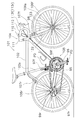
図1において、本発明の一実施形態を採用した自転車101は、ロードレーサであり、フロントフォーク98を有するダイヤモンド形のフレーム102と、フロントフォーク98に固定されたハンドル部104と、チェーン95やペダルPDが装着されたクランク96や前後のディレーラ(第1及び第2変速装置の一例)97f,97rや前後のスプロケット群99f,99r等からなる駆動部105と、フロントフォーク98及びフレーム102後部に装着された前輪及び後輪106f,106rと、前後のブレーキ装置107f,107rと、前後のディレーラ97f,97rを制御する変速制御装置110とを備えている。
[First Embodiment]
In FIG. 1, a
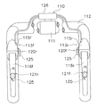
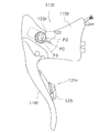
ハンドル部104は、ハンドルステム111と、ハンドルステム111の上端で嵌合固定されたハンドルバー112とで構成されている。ハンドルステム111は、フロントフォーク98の上部に嵌合固定されている。ハンドルバー112は、ドロップハンドル型のものであり、左右1対のブレーキレバー113f,113rを備えている。ブレーキレバー113f,113rは、図2から図4に示すように、ハンドルバー112の端部にそれぞれ装着される前後のブレーキブラケット115f,115rと、ブレーキブラケット115f,115rに揺動自在に装着される前後のレバー部材116f,116rとを有している。
The
ブレーキブラケット115f,115rの内側面及びレバー部材116f,116rの後面には、前後のディレーラ97f,97rの変速操作用の前後の変速操作部120f,120r(操作部の一例)及び前後の変速操作部121f,121r(操作部の一例)が各別に設けられている。前変速操作部120f及び後変速操作部120rは、後ブレーキブラケット115r及び前ブレーキブラケット115fに手をおいた状態で変速できるようにするために各別に設けられている。前変速操作部121f及び後変速操作部121rは、後レバー部材116r及び前レバー部材116fに手をおいた状態で変速できるようにするために各別に設けられている。
Front and rear
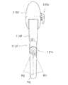
各変速操作部120f,120r、121f,121rは、中立位置P0と、中立位置P0から下方又は内方に揺動した第1位置P1と、中立位置P0から上方又は外方に揺動した第2位置P2とに揺動自在な変速操作部材125をそれぞれ有している。変速操作部材125は、中立位置P0に向けて付勢されている。また、変速操作部120f,121fには、図6に示すように、前第1スイッチ131f及び前第2スイッチ132fがそれぞれ内部に設けられている。変速操作部120r,121rにも同様に後第1スイッチ131r及び後第2スイッチ132rがそれぞれ内部に設けられている。なお、この実施形態では、第1位置P1に変速操作部材125が操作されると前後の第1スイッチ131f,131rがオンし、第2位置P2に変速操作部材125が操作されると前後の第2スイッチ132f,132rがオンするように構成されている。この組み合わせは適宜に設定される。
Each of the speed
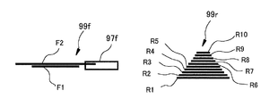
駆動部105は、図1に示すように、前述したチェーン95と、チェーン95の架け換えを行う前後のディレーラ97f,97rと、前後のスプロケット群99f,99rとを含んでいる。フロントディレーラ97fは、フレーム102のシートチューブ102aに設けられ2つの変速位置にチェーン95を案内する電気制御可能な電動ディレーラである。リアディレーラ97rは、フレーム102の後部に設けられた10の変速位置を有する電気制御可能な電動ディレーラである。
As shown in FIG. 1, the
これらのディレーラ97f,97rは、図示しない電源からの電力が供給されて動作する。各ディレーラ97f,97rには、図6に示すように、変速位置を検出する変速位置センサ133f,133rが設けられている。
These
前スプロケット群99fは、図5に示すように、クランク軸の軸方向に並べて配置された歯数が異なる2枚のスプロケットF1,F2を有している。後スプロケット群99rは、後輪のハブ軸に沿った軸方向に並べて配置された歯数が異なる10枚のスプロケットR1〜R10を有している。ここでは、内側にあるスプロケットF1が外側にあるスプロケットF2より歯数の少ない。また、最も内側にあるスプロケットR1から順に歯数が少なくなり、最も外側にあるスプロケットR10が最も歯数が少ない。前後のディレーラ97f,97rは、チェーン95を複数のスプロケットF1,F2,R1〜R10のいずれかに移動させて変速動作を行う。この変速操作は、変速操作部120f,120r、121f,121rにより行われる。
As shown in FIG. 5, the
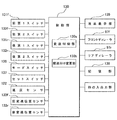
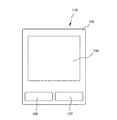
変速制御装置110は、図2、図6及び図7に示すように、たとえば、ハンドルバー112の中央に装着されたケース部材126と、ケース部材126に収納されたマイクロコンピュータからなる制御部130と、前述した変速操作部120f,120r、121f,121rとを有している。また、変速制御装置110は、ケース部材126に収納された液晶表示部135と、モードスイッチ136と、セットスイッチ137とを有している。制御部130には、変速操作部120f,120r、121f,121rを構成する前後の第1スイッチ131f,131r及び前後の第2スイッチ132f,132rと、フロントフォーク98に装着された速度センサ122と、前後のディレーラ97f,97rと、他の入出力部とが接続されている。また、制御部130には、モードスイッチ136と、セットスイッチ137と、前後の変速位置センサ133f,133rと、記憶部138とが接続されている。速度センサ122は、前輪106fのスポーク106sに装着された磁石123を検知することにより前輪106fの回転を検出する。なお、速度センサ122は無線又は有線で回転信号を制御部130に出力する。
As shown in FIGS. 2, 6, and 7, the
液晶表示部135は、自転車の速度、各ディレーラ97f,97rの変速位置、制御モード及び走行距離等を表示可能な、たとえばセグメント方式の液晶ディスプレイを用いている。
The liquid
モードスイッチ136(スイッチ関連付け操作部の一例)は、前後の第1及び第2スイッチ131f,131f,132r,132rをシフトダウン又はシフトアップに関連させる際及び変更する際に使用される。具体的には、モードスイッチ136を操作した状態で前後の変速操作部120f,121f,120r,121rを操作すると、オンした第1及び第2スイッチ131f,131r,132f,132rがフロントディレーラ97f又はリアディレーラ97rのシフトアップ動作SUに関連付けられ、オンしなかったスイッチがシフトダウン動作SDに関連付けられる。また、モードスイッチ136は、液晶表示部135の各種の表示モードを切り換えるためにも使用される。セットスイッチ137は、モードスイッチ136で選択されたモードを決定するために使用される。記憶部138には、各種のデータが記憶されている。たとえば、前後のディレーラ97f,97rの各変速段FS(FS=1,2),RS(RS=1−10)毎の変速位置(FP,RP)が変速位置センサ133f,133rの検出値に対応して記憶されている。また、前後の第1及び第2スイッチ131f,131f,132r,132rとシフトアップ動作SU及びシフトダウン動作SDとの関連が記憶されている。そして、前後の第1及び第2スイッチ131f,131f,132r,132rが操作されると、制御部130は、記憶部138に記憶された関連に基づいてシフトアップ及びシフトダウン制御を行う。
The mode switch 136 (an example of a switch association operation unit) is used when the front and rear first and
変速位置センサ133f,133rは、ディレーラ97f,97rの変速位置に検出するものであり、たとえばロータリエンコーダ等の回転位置検出手段により構成されている。
The
制御部130は、機能的な構成として、変速モードの時、前後の第1スイッチ131f,131r及び前後の第2スイッチ132f,132rからの信号及び前後の変速位置センサ133f,133rからの信号に応じて前後のディレーラ97f,97rを変速制御する変速制御部130aを有している。変速制御部130aは、速度センサ122及び変速位置センサ133f,133rからの信号により液晶表示部135に速度及び変速位置を表示するとともに走行距離も表示する。また、制御部130は、前後の第1スイッチ131f,131r及び前後の第2スイッチ132f,132rとシフトアップ及びシフトダウンの関連を変更する関連付け変更部130bを有している。
As a functional configuration, the
次に本発明によるディレーラの制御方法について、図8及び図9に示す制御フローチャートにしたがって説明する。 Next, the derailleur control method according to the present invention will be described with reference to the control flowcharts shown in FIGS.
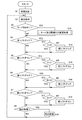
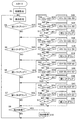
制御部130に電源が投入されると、ステップS1で初期設定がなされる。ここでは、各種のフラグや変数がリセットされる。また、前後の第1及び第2スイッチ131f,131r,132f,132rとシフトアップ及びシフトダウンの関連について記憶部138に記憶された内容が読み出されてマイクロコンピュータ内のメモリにセットされる。ステップS2では、表示処理が行われる。たとえば、速度センサ122から信号により速度や走行距離が液晶表示部135に表示される。ステップS3では、モードスイッチ136が操作されたか否かを判断する。ステップS4では、フロントディレーラ97fのシフトアップ操作がなされたか否かを判断する。フロントディレーラ97fのシフトアップ操作は、記憶部138に記憶され初期設定時にセットされた前第1及び第2スイッチ131f,132fとシフトアップSUとの関連又はその後に変更された関連により判断する。ステップS5では、変速操作部120f又は121fにより、フロントディレーラ97fのシフトダウン操作がなされたか否かを判断する。このシフトダウン操作も前第1及び第2スイッチ131f,132fとシフトダウンSDとの関連により判断する。ステップS6では、変速操作部120r又は121rにより、シフトアップ操作がなされたか否かを判断する。ステップS7では、変速操作部120r又は121rにより、リアディレーラ97rのシフトダウン操作がなされたか否かを判断する。これらのリアディレーラ97fの操作も後第1及び第2スイッチ131r,132rとシフトアップSU又はシフトダウンSDとの関連により判断する。ステップS8では、車輪径や変速段数の設定等の各種の設定を含む他の処理が選択されたか否かを判断してステップS2に戻る。
When power is turned on to the
モードスイッチ136が操作されたと判断すると、ステップS3からステップS10に移行する。ステップS10では、図9に示すモード及び関連付け変更処理が実行される。
If it is determined that the
フロントディレーラ97fのシフトアップ操作がなされた判断すると、ステップS4からステップS11に移行する。ステップS11では、フロントディレーラ97fの変速位置がスプロケットF2、つまり外側の大径の高速用のスプロケットの位置にあるか否かを判断する。変速位置がF2の場合、もうそれ以上シフトアップできないので何も処理をせずにステップS5に移行する。変速位置がF2でとないとき、つまり変速位置がF1のときには、ステップS11からステップS12に移行する。ステップS12では、フロントディレーラ97fを変速位置F2に移動させるシフトアップ制御を行い、ステップS5に移行する。
If it is determined that the
フロントディレーラ97fのシフトダウン操作がなされた判断すると、ステップS5からステップS13に移行する。ステップS13では、フロントディレーラ97fの変速位置がスプロケットF1、つまり内側の小径の低速用のスプロケットの位置にあるか否かを判断する。変速位置がF1の場合、もうそれ以上シフトダウンできないので何も処理をせずにステップS6に移行する。変速位置がF1でとないとき、つまり変速位置がF2のときには、ステップS13からステップS14に移行する。ステップS14では、フロントディレーラ97fを変速位置F1に移動させるシフトダウン制御を行い、ステップS6に移行する。
If it is determined that the
リアディレーラ97rのシフトアップ操作がなされた判断すると、ステップS6からステップS15に移行する。ステップS15では、リアディレーラ97rの変速位置がスプロケットR10、つまり外側の小径の高速用のスプロケットの位置にあるか否かを判断する。変速位置がR10の場合、もうそれ以上シフトアップできないので何も処理をせずにステップS7に移行する。変速位置がR10でとないときは、ステップS15からステップS16に移行する。ステップS16では、リアディレーラ97rの変速位置をひとつ外側のスプロケットに移動させるシフトアップ制御を行い、ステップS7に移行する。
If it is determined that the
リアディレーラ97rのシフトダウン操作がなされた判断すると、ステップS7からステップS17に移行する。ステップS17では、リアディレーラ97rの変速位置がスプロケットR1、つまり内側の大径の低速用のスプロケットの位置にあるか否かを判断する。変速位置がR1の場合、もうそれ以上シフトダウンできないので何も処理をせずにステップS8に移行する。変速位置がR1でとないときには、ステップS11からステップS18に移行する。ステップS18では、リアディレーラ97rの変速位置をひとつ内側のスプロケットに移動させるシフトダウン制御を行い、ステップS8に移行する。
If it is determined that the downshift operation of the
他の処理と判断すると、ステップS8からステップS19に移行して選択されたの処理を行う。 If it is determined that the process is another process, the process proceeds from step S8 to step S19 to perform the selected process.
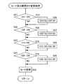
モード及び関連付け変更処理では、図9のステップS21でモードスイッチ136が操作された状態で前第1スイッチ131fがオンしたか否かを判断する。変速操作部120f,121fを第1位置P1側に操作すると、前第1スイッチ131fがオンする。ステップS22では、モードスイッチ136が操作された状態で前第2スイッチ132fがオンしたか否かを判断する。変速操作部120f,121fを第2位置P2側に操作すると、前第2スイッチ132fがオンする。ステップS23では、モードスイッチ136が操作された状態で後第1スイッチ131rがオンしたか否かを判断する。変速操作部120r,121rを第1位置P1側に操作すると、後第1スイッチ131rがオンする。ステップS24では、モードスイッチ136が操作された状態で後第2スイッチ132rがオンしたか否かを判断する。変速操作部120r,121rを第2位置P2側に操作すると、後第2スイッチ132rがオンする。前後の第1及び第2スイッチ131f,131r,132f,132rがオンしていない場合は、ステップS25でモード処理を行う。モード処理では、モードスイッチ136を押す都度モードが種々に切り換わる。
In the mode and association change process, it is determined whether or not the previous
モードスイッチ136が操作された状態で前第1スイッチ131fがオンしたと判断すると、ステップS21からステップS26に移行する。ステップS26では、オンした前第1スイッチ131fをシフトアップ動作SUに関連付け、オンしていない前第2スイッチ132fをシフトダウン操作SDに関連付ける。モードスイッチ136が操作された状態で前第2スイッチ132fがオンしたと判断すると、ステップS22からステップS27に移行する。ステップS27では、オンした前第2スイッチ132fをシフトアップ動作SUに関連付け、オンしていない前第1スイッチ131fをシフトダウン操作SDに関連付ける。モードスイッチ136が操作された状態で後第1スイッチ131rがオンしたと判断すると、ステップS23からステップS28に移行する。ステップS28では、オンした後第1スイッチ131rをシフトアップ動作SUに関連付け、オンしていない後第2スイッチ132rをシフトダウン操作SDに関連付ける。モードスイッチ136が操作された状態で後第2スイッチ132rがオンしたと判断すると、ステップS24からステップS29に移行する。ステップS29では、オンした後第2スイッチ132rをシフトアップ動作SUに関連付け、オンしていない後第1スイッチ131rをシフトダウン動作SDに関連付ける。これらの関連付けられた結果は記憶部138に記憶されるとともにマイクロコンピュータ内のメモリにセットされる。
When it is determined that the front
ここでは、前後の第1及び第2スイッチ131f,132f,131r,132rとシフトアップ動作及びシフトダウン動作との関連づけを変更可能であるので、シフトアップ及びシフトダウンのスイッチ操作を容易に変更できるようになる。
Here, since the association between the front and rear first and
〔第2実施形態〕
第1実施形態では、モードスイッチ136と前後の第1及び第2スイッチ131f,131r,132f,132rとの同時操作でスイッチの関連づけを変更したが、図10に示す第2実施形態では、前変速操作部120f,121fと後変速操作部120r,121rとの同時操作で後変速操作部120r,121rのスイッチの関連づけを変更可能にしている。なお、以降のフローチャートにおいて第1実施形態と同一部材及び同一ステップに対しては同じ符号を付している。
[Second Embodiment]
In the first embodiment, the switch association is changed by simultaneous operation of the
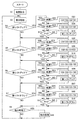
第2実施形態では、ステップS4とステップS11との間、ステップS5とステップS13との間、ステップS6とステップS15との間及びステップS7とステップS17との間にそれぞれ関連づけの変更処理がなされる。 In the second embodiment, the association changing process is performed between step S4 and step S11, between step S5 and step S13, between step S6 and step S15, and between step S7 and step S17. .
すなわち、前シフトアップ操作がなされると、ステップS4からステップS31に移行する。ステップS31では、前シフトアップ操作がなされている状態で後第1スイッチ131rがオンしたか否かを判断する。ステップS32では、前シフトアップ操作がなされている状態で後第2スイッチ132rがオンしたか否かを判断する。これらの同時操作がなされていない場合はステップS11に移行して通常の前シフトアップ処理を行う。
That is, when a previous upshift operation is performed, the process proceeds from step S4 to step S31. In step S31, it is determined whether or not the rear
前シフトアップ操作がなされている状態で後第1スイッチ131rがオンしている場合は、ステップS31からステップS33に移行する。ステップS33では、オンした後第1スイッチ131rをシフトアップ動作SUに関連付け、オンしていない後第2スイッチ132rをシフトダウン操作SDに関連付ける。前シフトアップ操作がなされている状態で後第2スイッチ132rがオンしている場合は、ステップS32からステップS34に移行する。ステップS34では、オンした後第2スイッチ132rをシフトアップ動作SUに関連付け、オンしていない後第1スイッチ131rをシフトダウン操作SDに関連付ける。
When the rear
前シフトダウン操作がなされると、ステップS5からステップS36に移行する。ステップS36では、前シフトダウン操作がなされている状態で後第1スイッチ131rがオンしたか否かを判断する。ステップS37では、前シフトダウン操作がなされている状態で後第2スイッチ132rがオンしたか否かを判断する。前シフトダウン操作がなされている状態で後第1スイッチ131rがオンしている場合は、ステップS36からステップS38に移行する。ステップS38では、オンした後第1スイッチ131rをシフトアップ動作SUに関連付け、オンしていない後第2スイッチ132rをシフトダウン操作SDに関連付ける。前シフトダウン操作がなされている状態で後第2スイッチ132rがオンしている場合は、ステップS37からステップS39に移行する。ステップS39では、オンした後第2スイッチ132rをシフトアップ動作SUに関連付け、オンしていない後第1スイッチ131rをシフトダウン操作SDに関連付ける。
When a previous downshift operation is performed, the process proceeds from step S5 to step S36. In step S36, it is determined whether or not the rear
後シフトアップ操作がなされると、ステップS6からステップS41に移行する。ステップS41では、後シフトアップ操作がなされている状態で前第1スイッチ131fがオンしたか否かを判断する。ステップS42では、後シフトアップ操作がなされている状態で前第2スイッチ132fがオンしたか否かを判断する。後シフトアップ操作がなされている状態で前第1スイッチ131fがオンしている場合は、ステップS41からステップS43に移行する。ステップS43では、オンした前第1スイッチ131fをシフトアップ動作SUに関連付け、オンしていない前第2スイッチ132fをシフトダウン操作SDに関連付ける。後シフトアップ操作がなされている状態で前第2スイッチ132fがオンしている場合は、ステップS42からステップS44に移行する。ステップS44では、オンした前第2スイッチ132fをシフトアップ動作SUに関連付け、オンしていない前第1スイッチ131fをシフトダウン操作SDに関連付ける。
When the rear shift-up operation is performed, the process proceeds from step S6 to step S41. In step S41, it is determined whether or not the front
後シフトダウン操作がなされると、ステップS7からステップS45に移行する。ステップS45では、後シフトダウン操作がなされている状態で前第1スイッチ131fがオンしたか否かを判断する。ステップS46では、後シフトダウン操作がなされている状態で前第2スイッチ132fがオンしたか否かを判断する。後シフトダウン操作がなされている状態で前第1スイッチ131fがオンしている場合は、ステップS44からステップS47に移行する。ステップS47では、オンした後第1スイッチ131fをシフトアップ動作SUに関連付け、オンしていない前第2スイッチ132fをシフトダウン操作SDに関連付ける。後シフトダウン操作がなされている状態で前第2スイッチ132けがオンしている場合は、ステップS46からステップS48に移行する。ステップS48では、オンした前第2スイッチ132fをシフトアップ動作SUに関連付け、オンしていない前第1スイッチ131fをシフトダウン操作SDに関連付ける。
When the rear shift-down operation is performed, the process proceeds from step S7 to step S45. In step S45, it is determined whether or not the front
このような構成の第2実施形態では、前後のディレーラ97f,97rを変速操作するために別々に設けられた前後の変速操作部120f,121f,120r,121rの一方が操作された状態で他方の変速操作部を操作すると、操作された位置でオンするスイッチ及びオンしないスイッチの関連づけを変更できるので、スイッチの関連付け操作のための操作部を設けることなく2つのスイッチの関連づけを一度に変更できる。
In the second embodiment having such a configuration, one of the front and rear
〔第3実施形態〕
第3実施形態では、前後の変速操作部120f,121f,120r,121rの長押し操作により長押しされた時にオンするスイッチ及びオンしないスイッチの関連付けを変更している。
[Third Embodiment]
In the third embodiment, the association between a switch that is turned on and a switch that is not turned on when the button is long-pressed by a long-pressing operation of the front and rear
図11において、第2実施形態と同様に、ステップS4とステップS11との間、ステップS5とステップS13との間、ステップS6とステップS15との間及びステップS7とステップS17との間にそれぞれ関連づけの変更処理がなされる。 In FIG. 11, as in the second embodiment, there is an association between step S4 and step S11, between step S5 and step S13, between step S6 and step S15, and between step S7 and step S17. The change process is performed.
すなわち、前シフトアップ操作がなされると、ステップS4からステップS51に移行する。ステップS51及びステップS52では、前第1スイッチ131f及び前第2スイッチ132fのいずれかが所定時間以上の長押し(たとえば2秒以上の時間)操作されたか否かを判断する。長押しされていなければステップS11に移行して通常の前シフトアップ処理を行う。
That is, when a previous upshift operation is performed, the process proceeds from step S4 to step S51. In step S51 and step S52, it is determined whether or not any of the front
前第1スイッチ131fが長押しされた場合は、ステップS51からステップS53に移行する。ステップS53では、オンした前第1スイッチ131fをシフトアップ動作SUに関連付け、オンしていない前第2スイッチ132fをシフトダウン操作SDに関連付ける。前第2スイッチ132fが長押しされた場合は、ステップS52からステップS54に移行する。ステップS54では、オンした前第2スイッチ132fをシフトアップ動作SUに関連付け、オンしていない前第1スイッチ131fをシフトダウン操作SDに関連付ける。
When the front
前シフトダウン操作がなされると、ステップS5からステップS56に移行する。ステップS56及びステップS57では、前第1スイッチ131f及び前第2スイッチ132fのいずれかが所定時間以上の長押しされたか否かを判断する。長押しされていなければステップS13に移行して通常の前シフトダウン処理を行う。前第1スイッチ131fが長押しされた場合は、ステップS56からステップS58に移行する。ステップS58では、オンした前第1スイッチ131fをシフトアップ動作SUに関連付け、オンしていない前第2スイッチ132fをシフトダウン操作SDに関連付ける。前第2スイッチ132fが長押しされた場合は、ステップS57からステップS59に移行する。ステップS59では、オンした前第2スイッチ132fをシフトアップ動作SUに関連付け、オンしていない前第1スイッチ131fをシフトダウン操作SDに関連付ける。
When the previous downshift operation is performed, the process proceeds from step S5 to step S56. In step S56 and step S57, it is determined whether any of the front
後シフトアップ操作がなされると、ステップS6からステップS61に移行する。ステップS61及びステップS62では、後第1スイッチ131r及び後第2スイッチ132rのいずれかが所定時間以上の長押しされたか否かを判断する。長押しされていなければステップS15に移行して通常の後シフトアップ処理を行う。後第1スイッチ131rが長押しされた場合は、ステップS61からステップS63に移行する。ステップS63では、オンした後第1スイッチ131rをシフトアップ動作SUに関連付け、オンしていない後第2スイッチ132rをシフトダウン操作SDに関連付ける。後第2スイッチ132rが長押しされた場合は、ステップS62からステップS64に移行する。ステップS64では、オンした後第2スイッチ132rをシフトアップ動作SUに関連付け、オンしていない後第1スイッチ131rをシフトダウン操作SDに関連付ける。
When the rear shift-up operation is performed, the process proceeds from step S6 to step S61. In step S61 and step S62, it is determined whether any of the rear
後シフトダウン操作がなされると、ステップS7からステップS65に移行する。ステップS65及びステップS66では、後第1スイッチ131r及び後第2スイッチ132rのいずれかが所定時間以上の長押しされたか否かを判断する。長押しされていなければステップS17に移行して通常の後シフトダウン処理を行う。後第1スイッチ131rが長押しされた場合は、ステップS65からステップS67に移行する。ステップS67では、オンした後第1スイッチ131rをシフトアップ動作SUに関連付け、オンしていない後第2スイッチ132rをシフトダウン操作SDに関連付ける。後第2スイッチ132rが長押しされた場合は、ステップS66からステップS68に移行する。ステップS68では、オンした後第2スイッチ132rをシフトアップ動作SUに関連付け、オンしていない後第1スイッチ131rをシフトダウン操作SDに関連付ける。
When a rear downshift operation is performed, the process proceeds from step S7 to step S65. In step S65 and step S66, it is determined whether any of the rear
ここでは、2つのスイッチのいずれかの長押し等の特殊な操作によりスイッチの関連付け操作を行えるので、スイッチの関連付け操作のための操作部を設けることなく2つのスイッチの関連づけを一度に変更できる。 Here, since the switch association operation can be performed by a special operation such as long pressing of either of the two switches, the association of the two switches can be changed at a time without providing an operation unit for the switch association operation.
なお、第3実施形態では、変速操作部の長押しにより関連付けを変更する処理を例示したが、ダブルクリック等の特殊な操作であればどのような操作でもよい。 In the third embodiment, the process of changing the association by long-pressing the speed change operation unit is exemplified, but any operation may be used as long as it is a special operation such as a double click.
〔他の実施形態〕
(a)前記実施形態では、ロードタイプの自転車の変速制御装置を例に説明したが、自転車の形態は変速装置を有するものであればどのような形態でもよい。
[Other Embodiments]
(A) In the above-described embodiment, the transmission control device for a road type bicycle has been described as an example. However, the bicycle may have any form as long as it has a transmission.
(b)前記実施形態では、前後のディレーラ等の2つの変速装置は何れも電動制御可能であったが、いずれか一方の変速装置が電動制御可能であればよい。 (B) In the above-described embodiment, the two transmissions such as the front and rear derailleurs can be electrically controlled. However, any one of the transmissions only needs to be electrically controlled.
(c)前記実施形態では、電動ディレーラを例に本発明を説明したが内装変速ハブを有する内装変速装置の制御装置にも本発明を適用できる。 (C) In the above embodiment, the present invention has been described by taking an electric derailleur as an example. However, the present invention can also be applied to a control device for an internal transmission having an internal transmission hub.
(d)前記第2実施形態では、前後のディレーラの変速操作部の同時操作によりスイッチの関連づけを変更したが、たとえば、リアディレーラと内装変速装置との2つの変速装置の2つの変速操作部の同時操作によりスイッチの関連づけを変更してもよい。 (D) In the second embodiment, the association of the switches is changed by the simultaneous operation of the shift operation units of the front and rear derailleurs. For example, the two shift operation units of the two transmissions of the rear derailleur and the internal transmission are simultaneously operated. The switch association may be changed by an operation.
97f フロントディレーラ(変速装置の一例)
97f リアディレーラ(変速装置の一例)
110 変速制御装置
120f,121f 前変速操作部(操作部の一例)
120r,121r 後変速操作部(操作部の一例)
130 制御部
130a 変速制御部
130b 関連付け変更部
131f 前第1スイッチ
132f 前第2スイッチ
131r 後第1スイッチ
132r 後第2スイッチ
97f Front derailleur (an example of a transmission)
97f Rear derailleur (an example of a transmission)
110
120r, 121r Rear shift operation unit (an example of an operation unit)
130
Claims (9)
第1スイッチと、
前記第1スイッチと異なる位置に配置される第2スイッチと、
前記第1スイッチ及び第2スイッチと、前記自転車用変速装置のシフトアップ動作及びシフトダウン動作との関連付けを変更可能なスイッチ関連付け変更部と、
前記第1及び第2スイッチのうち、前記シフトアップ動作に関連づけられたスイッチにより前記自転車用変速装置をシフトアップし、前記シフトダウン動作に関連づけられたスイッチにより前記自転車用変速装置をシフトダウンする変速制御部と、
を備えた自転車用変速制御装置。 A bicycle shift control device for controlling a bicycle transmission having a plurality of shift stages,
A first switch;
A second switch disposed at a different position from the first switch;
A switch association changing unit capable of changing association between the first switch and the second switch, and a shift-up operation and a shift-down operation of the bicycle transmission device;
Of the first and second switches, a shift that shifts up the bicycle transmission with a switch associated with the upshift operation, and a downshift with the switch associated with the downshift operation. A control unit;
A shift control device for a bicycle comprising
前記変速制御部は、前記第1及び第2スイッチのうち、前記シフトアップ動作に関連づけられたスイッチがオンするように前記操作部が操作されると、前記自転車用変速装置をシフトアップし、前記シフトダウン動作に関連づけられたスイッチがオンするように前記操作部が操作されると、前記自転車用変速装置をシフトダウンする、請求項1に記載の自転車用変速制御装置。 It is movable between a first position and a second position different from the first position, and when it moves to the first position or when the first switch turns on during the movement process and moves to the second position Or an operation unit for turning on the second switch in the course of movement;
The shift control unit shifts up the bicycle transmission when the operation unit is operated such that a switch associated with the shift-up operation is turned on among the first and second switches, The bicycle transmission control device according to claim 1, wherein when the operation unit is operated so that a switch associated with a shift-down operation is turned on, the bicycle transmission device is shifted down.
スイッチ関連付け操作部を有し、前記スイッチ関連付け操作部が操作された状態で前記第1及び第2スイッチのいずれかをオンさせると、オンしたスイッチをシフトアップスイッチとシフトダウンスイッチのいずれか一方として関連付け、オンしなかったスイッチをいずれか他方として関連付ける、請求項1から3のいずれか1項に記載の自転車用変速制御装置。 The switch association changing unit
When a switch association operation unit is provided and one of the first and second switches is turned on while the switch association operation unit is operated, the turned-on switch is set as one of a shift-up switch and a shift-down switch. The bicycle transmission control device according to any one of claims 1 to 3, wherein a switch that has not been associated and turned on is associated as one of the other.
スイッチ関連付け操作部を有し、前記スイッチ関連付け操作部が操作された状態で前記操作部が前記第1及び第2位置のいずれかに操作されると、操作された位置でオンするスイッチをシフトアップスイッチとシフトダウンスイッチのいずれか一方として関連付け、オンしなかったスイッチをいずれか他方として関連付ける、請求項2又は3に記載の自転車用変速制御装置。 The switch association changing unit
A switch associating operation unit is provided, and when the operation unit is operated to one of the first and second positions while the switch association operation unit is operated, a switch that is turned on at the operated position is shifted up. The bicycle shift control device according to claim 2 or 3, wherein the switch and the downshift switch are associated with each other, and the switch that has not been turned on is associated with the other.
前記操作部は、前記第1変速装置を変速操作するための前記第1及び第2スイッチを選択的にオンする第1変速操作部と、前記第2変速装置を変速操作するための前記第1及び第2スイッチを選択的にオンする第2変速操作部とを有し、
前記スイッチ関連付け変更部は、前記第1変速操作部及び第2変速操作部の一方が操作された状態で前記第1変速操作部及び第2変速操作部の他方が前記第1及び第2位置のいずれかに操作されると、操作された位置でオンするスイッチを前記他方の変速操作部のシフトアップスイッチとシフトダウンスイッチのいずれか一方として関連付け、オンしなかったスイッチをいずれか他方として関連付ける、請求項2又は3に記載の自転車用変速制御装置。 The bicycle transmission has a first transmission and a second transmission different from the first transmission,
The operation unit includes a first shift operation unit that selectively turns on the first and second switches for shifting the first transmission, and the first for shifting the second transmission. And a second shift operation unit that selectively turns on the second switch,
The switch association changing unit is configured such that one of the first shift operation unit and the second shift operation unit is operated and the other of the first shift operation unit and the second shift operation unit is in the first and second positions. When operated to any one, the switch that is turned on at the operated position is associated as either one of the shift-up switch and the shift-down switch of the other shift operation unit, and the switch that is not turned on is associated as one of the other, The bicycle shift control device according to claim 2 or 3.
オンオフ操作可能な第1及び第2スイッチと、前記自転車用変速装置のシフトアップ動作及びシフトダウン動作とをそれぞれ関連付ける第1工程と、
前記第1工程で関連付けられたスイッチとシフト動作方向との関係を変更する第2工程と、
を含む自転車用変速装置の制御方法。 A control method for a bicycle transmission having a plurality of shift stages,
A first step of associating first and second switches that can be turned on and off with a shift-up operation and a shift-down operation of the bicycle transmission, respectively;
A second step of changing a relationship between the switch and the shift operation direction associated in the first step;
Control method for bicycle transmission including
Priority Applications (6)
| Application Number | Priority Date | Filing Date | Title |
|---|---|---|---|
| JP2004115582A JP2005297712A (en) | 2004-04-09 | 2004-04-09 | Speed-change control device for bicycle and control method |
| TW094106660A TWI257910B (en) | 2004-04-09 | 2005-03-04 | Speed-change control device for bicycle and control method |
| CNB2005100527241A CN100379644C (en) | 2004-04-09 | 2005-03-09 | Speed change control device and control method for bicycle |
| US10/907,547 US7730803B2 (en) | 2004-04-09 | 2005-04-05 | Switch designation apparatus for a bicycle control unit |
| DE602005005378T DE602005005378T2 (en) | 2004-04-09 | 2005-04-06 | Shifting direction fixing device for a bicycle control unit |
| EP05007567A EP1584552B1 (en) | 2004-04-09 | 2005-04-06 | Switch designation apparatus for a bicycle control unit |
Applications Claiming Priority (1)
| Application Number | Priority Date | Filing Date | Title |
|---|---|---|---|
| JP2004115582A JP2005297712A (en) | 2004-04-09 | 2004-04-09 | Speed-change control device for bicycle and control method |
Publications (1)
| Publication Number | Publication Date |
|---|---|
| JP2005297712A true JP2005297712A (en) | 2005-10-27 |
Family
ID=34909542
Family Applications (1)
| Application Number | Title | Priority Date | Filing Date |
|---|---|---|---|
| JP2004115582A Pending JP2005297712A (en) | 2004-04-09 | 2004-04-09 | Speed-change control device for bicycle and control method |
Country Status (6)
| Country | Link |
|---|---|
| US (1) | US7730803B2 (en) |
| EP (1) | EP1584552B1 (en) |
| JP (1) | JP2005297712A (en) |
| CN (1) | CN100379644C (en) |
| DE (1) | DE602005005378T2 (en) |
| TW (1) | TWI257910B (en) |
Cited By (3)
| Publication number | Priority date | Publication date | Assignee | Title |
|---|---|---|---|---|
| DE102016214078A1 (en) | 2015-07-29 | 2017-02-02 | Shimano Inc. | Operating control unit and bicycle indicator |
| JP2018089989A (en) * | 2016-11-30 | 2018-06-14 | 株式会社シマノ | Electronic device and control method in electronic device |
| CN110027661A (en) * | 2016-01-15 | 2019-07-19 | 株式会社岛野 | Electric bicycle operating system, electric speed changer and electric seat bar assembly |
Families Citing this family (29)
| Publication number | Priority date | Publication date | Assignee | Title |
|---|---|---|---|---|
| US7703350B2 (en) * | 2006-02-01 | 2010-04-27 | Shimano Inc. | Bicycle control device |
| US20070193387A1 (en) * | 2006-02-03 | 2007-08-23 | Shimano Inc. | Bicycle shift control device |
| US20070193388A1 (en) * | 2006-02-03 | 2007-08-23 | Shimano Inc. | Bicycle shift control device |
| US20070207885A1 (en) | 2006-03-06 | 2007-09-06 | Shimano Inc. | Electronic derailleur control system |
| KR20060066698A (en) * | 2006-05-29 | 2006-06-16 | 김기천 | Bicycle transmission |
| JP4366390B2 (en) * | 2006-10-13 | 2009-11-18 | 株式会社シマノ | Bicycle handlebar assembly |
| ITMI20071181A1 (en) * | 2007-06-12 | 2008-12-13 | Campagnolo Srl | ELECTRONIC CONTROL METHOD OF A BICYCLE CHANGE AND ELECTRONIC BICYCLE SYSTEM |
| EP2088071B1 (en) * | 2008-02-06 | 2013-12-11 | Campagnolo S.r.l. | Method for electronically controlling a bicycle gearshift and electronic system for a bicycle |
| US8286529B2 (en) | 2009-01-26 | 2012-10-16 | Shimano Inc. | Bicycle control device |
| US7900946B2 (en) * | 2009-03-31 | 2011-03-08 | Shimano Inc. | Bicycle shifting control apparatus |
| US8297143B2 (en) | 2009-05-19 | 2012-10-30 | Shimano Inc. | Electrical bicycle shift control device |
| WO2012068265A1 (en) * | 2010-11-18 | 2012-05-24 | Sean Michael Simpson | System and method for controlling a transmission of a human-powered vehicle |
| JP2012179975A (en) | 2011-02-28 | 2012-09-20 | Shimano Inc | Setting device of suspension control device for bicycle and suspension control device for bicycle |
| US8886417B2 (en) | 2011-09-09 | 2014-11-11 | Sram, Llc | Bicycles with electronic shifting systems and methods |
| US9056651B2 (en) | 2012-08-27 | 2015-06-16 | Shimano Inc. | Bicycle control device |
| US9090304B2 (en) | 2012-08-27 | 2015-07-28 | Shimano Inc. | Bicycle control device |
| US9157523B2 (en) * | 2013-05-27 | 2015-10-13 | Shimano Inc. | Bicycle component actuation apparatus |
| JP2016020124A (en) * | 2014-07-14 | 2016-02-04 | 株式会社シマノ | Control device for bicycle |
| US11801913B2 (en) | 2015-03-05 | 2023-10-31 | Shimano Inc. | Bicycle electric component setting system |
| US9944350B2 (en) | 2016-01-11 | 2018-04-17 | Sram, Llc | Chain guide sensor and methods of controling a bicycle |
| US10745081B2 (en) * | 2017-07-28 | 2020-08-18 | Shimano Inc. | Bicycle rear derailleur and bicycle shifting control apparatus |
| JP6921724B2 (en) * | 2017-11-30 | 2021-08-18 | 株式会社シマノ | Shift control device and electric shift system |
| TWI673202B (en) * | 2018-11-16 | 2019-10-01 | Tektro Technology Corporation | Bicycle component control method |
| US11192609B2 (en) * | 2018-12-27 | 2021-12-07 | Shimano Inc. | Shift control device and gear shifting device |
| US11407473B2 (en) * | 2019-07-29 | 2022-08-09 | Shimano Inc. | Operating device and assist driving system for human-powered vehicle |
| US11407474B2 (en) * | 2019-07-29 | 2022-08-09 | Shimano Inc. | Operating device for human-powered vehicle |
| US11440611B2 (en) * | 2019-07-29 | 2022-09-13 | Shimano Inc. | Operating apparatus for human-powered vehicle |
| US12275495B2 (en) | 2021-09-21 | 2025-04-15 | Shimano Inc. | Electrical device and system for human-powered vehicle |
| US12509184B2 (en) | 2023-08-17 | 2025-12-30 | Shimano Inc. | Electric device of human-powered vehicle |
Citations (7)
| Publication number | Priority date | Publication date | Assignee | Title |
|---|---|---|---|---|
| JPH0623065Y2 (en) * | 1984-12-20 | 1994-06-15 | アルパイン株式会社 | Function setting device |
| JPH06266500A (en) * | 1993-03-15 | 1994-09-22 | Toshiba Corp | Input device |
| JP2001267002A (en) * | 2000-03-17 | 2001-09-28 | Fujitsu General Ltd | Door opening and closing structure |
| JP2002137786A (en) * | 2000-09-13 | 2002-05-14 | Shimano Inc | Shift control system and control method for bicycle transmission and bicycle |
| JP2003083597A (en) * | 2001-09-07 | 2003-03-19 | Sanyo Electric Co Ltd | Remote controller for air conditioner |
| JP2003153052A (en) * | 2001-11-08 | 2003-05-23 | Canon Inc | Digital camera with built-in printer |
| JP2004053700A (en) * | 2002-07-17 | 2004-02-19 | Funai Electric Co Ltd | Photographing device |
Family Cites Families (8)
| Publication number | Priority date | Publication date | Assignee | Title |
|---|---|---|---|---|
| US4490127A (en) * | 1981-05-29 | 1984-12-25 | Sanyo Electric Co., Ltd. | Electrically operated transmission gear system for bicycles |
| JPH03231006A (en) | 1990-02-05 | 1991-10-15 | Bridgestone Corp | Pneumatic tire for bicycle |
| DE4212319A1 (en) * | 1992-04-13 | 1993-10-14 | Fichtel & Sachs Ag | control device |
| US5514041A (en) * | 1994-11-21 | 1996-05-07 | Hsu; Yi-Hsung | Electronic bicycle derailleur control apparatus |
| JP3231006B2 (en) * | 1997-08-28 | 2001-11-19 | 株式会社シマノ | Gear change control device for bicycle |
| JP3522226B2 (en) * | 2001-03-07 | 2004-04-26 | 株式会社シマノ | Gear change control device for bicycle |
| DE10153487B4 (en) * | 2001-10-22 | 2007-07-12 | Graf, Friedrich, Dipl.-Ing. (Fh) | A computerized bicycle control system and method of controlling a bicycle transmission |
| US6734376B2 (en) * | 2002-06-19 | 2004-05-11 | Shimano Inc. | Electrical switch device for bicycle |
-
2004
- 2004-04-09 JP JP2004115582A patent/JP2005297712A/en active Pending
-
2005
- 2005-03-04 TW TW094106660A patent/TWI257910B/en not_active IP Right Cessation
- 2005-03-09 CN CNB2005100527241A patent/CN100379644C/en not_active Expired - Lifetime
- 2005-04-05 US US10/907,547 patent/US7730803B2/en active Active
- 2005-04-06 DE DE602005005378T patent/DE602005005378T2/en not_active Expired - Lifetime
- 2005-04-06 EP EP05007567A patent/EP1584552B1/en not_active Expired - Lifetime
Patent Citations (7)
| Publication number | Priority date | Publication date | Assignee | Title |
|---|---|---|---|---|
| JPH0623065Y2 (en) * | 1984-12-20 | 1994-06-15 | アルパイン株式会社 | Function setting device |
| JPH06266500A (en) * | 1993-03-15 | 1994-09-22 | Toshiba Corp | Input device |
| JP2001267002A (en) * | 2000-03-17 | 2001-09-28 | Fujitsu General Ltd | Door opening and closing structure |
| JP2002137786A (en) * | 2000-09-13 | 2002-05-14 | Shimano Inc | Shift control system and control method for bicycle transmission and bicycle |
| JP2003083597A (en) * | 2001-09-07 | 2003-03-19 | Sanyo Electric Co Ltd | Remote controller for air conditioner |
| JP2003153052A (en) * | 2001-11-08 | 2003-05-23 | Canon Inc | Digital camera with built-in printer |
| JP2004053700A (en) * | 2002-07-17 | 2004-02-19 | Funai Electric Co Ltd | Photographing device |
Cited By (8)
| Publication number | Priority date | Publication date | Assignee | Title |
|---|---|---|---|---|
| DE102016214078A1 (en) | 2015-07-29 | 2017-02-02 | Shimano Inc. | Operating control unit and bicycle indicator |
| JP2017030395A (en) * | 2015-07-29 | 2017-02-09 | 株式会社シマノ | Operation control device and bicycle display device |
| US10252762B2 (en) | 2015-07-29 | 2019-04-09 | Shimano Inc. | Operation control apparatus and bicycle display |
| CN110027661A (en) * | 2016-01-15 | 2019-07-19 | 株式会社岛野 | Electric bicycle operating system, electric speed changer and electric seat bar assembly |
| CN110027661B (en) * | 2016-01-15 | 2021-11-23 | 株式会社岛野 | Electric bicycle operating system, electric speed changer and electric seat post assembly |
| JP2018089989A (en) * | 2016-11-30 | 2018-06-14 | 株式会社シマノ | Electronic device and control method in electronic device |
| JP2021104807A (en) * | 2016-11-30 | 2021-07-26 | 株式会社シマノ | Road bike operating device |
| JP7560404B2 (en) | 2016-11-30 | 2024-10-02 | 株式会社シマノ | Control device for road bikes |
Also Published As
| Publication number | Publication date |
|---|---|
| EP1584552B1 (en) | 2008-03-19 |
| EP1584552A2 (en) | 2005-10-12 |
| CN100379644C (en) | 2008-04-09 |
| DE602005005378D1 (en) | 2008-04-30 |
| EP1584552A3 (en) | 2006-08-02 |
| TWI257910B (en) | 2006-07-11 |
| US7730803B2 (en) | 2010-06-08 |
| US20050223840A1 (en) | 2005-10-13 |
| CN1680167A (en) | 2005-10-12 |
| TW200540061A (en) | 2005-12-16 |
| DE602005005378T2 (en) | 2009-04-30 |
Similar Documents
| Publication | Publication Date | Title |
|---|---|---|
| JP2005297712A (en) | Speed-change control device for bicycle and control method | |
| CN100581916C (en) | Gear shift control device for bicycle | |
| US8475305B2 (en) | Method and apparatus for shifting a bicycle transmission | |
| EP1832504B1 (en) | Electronic derailleur control system | |
| US8882122B2 (en) | Bicycle gear changing apparatus | |
| JP4191757B2 (en) | Bicycle shift control device | |
| US9469377B2 (en) | Bicycle gear changing apparatus | |
| JP2005238873A (en) | Bicycle speed change control device and front derailleur control method | |
| US7547263B2 (en) | Apparatus for adjusting a position of a bicycle control device | |
| JP4266986B2 (en) | Bicycle display device and bicycle control device | |
| JP2005297655A (en) | Speed-change control device for bicycle and control method of front derailleur | |
| JP2005313748A (en) | Speed-change controller for cycles | |
| JP3566682B2 (en) | Bicycle shift control device and manual shift control device used therefor | |
| US7522033B2 (en) | Signal generating apparatus for a bicycle control device | |
| JP2003130197A (en) | Bicycle shift control device and bicycle shift control method |
Legal Events
| Date | Code | Title | Description |
|---|---|---|---|
| A977 | Report on retrieval |
Free format text: JAPANESE INTERMEDIATE CODE: A971007 Effective date: 20060629 |
|
| A131 | Notification of reasons for refusal |
Free format text: JAPANESE INTERMEDIATE CODE: A131 Effective date: 20060704 |
|
| A02 | Decision of refusal |
Free format text: JAPANESE INTERMEDIATE CODE: A02 Effective date: 20071113 |