EP2020371B1 - Bicycle control device - Google Patents
Bicycle control device Download PDFInfo
- Publication number
- EP2020371B1 EP2020371B1 EP08154527A EP08154527A EP2020371B1 EP 2020371 B1 EP2020371 B1 EP 2020371B1 EP 08154527 A EP08154527 A EP 08154527A EP 08154527 A EP08154527 A EP 08154527A EP 2020371 B1 EP2020371 B1 EP 2020371B1
- Authority
- EP
- European Patent Office
- Prior art keywords
- operating part
- gearshift operating
- gearshift
- control device
- brake lever
- Prior art date
- Legal status (The legal status is an assumption and is not a legal conclusion. Google has not performed a legal analysis and makes no representation as to the accuracy of the status listed.)
- Active
Links
Images


Classifications
-
- B—PERFORMING OPERATIONS; TRANSPORTING
- B62—LAND VEHICLES FOR TRAVELLING OTHERWISE THAN ON RAILS
- B62K—CYCLES; CYCLE FRAMES; CYCLE STEERING DEVICES; RIDER-OPERATED TERMINAL CONTROLS SPECIALLY ADAPTED FOR CYCLES; CYCLE AXLE SUSPENSIONS; CYCLE SIDE-CARS, FORECARS, OR THE LIKE
- B62K23/00—Rider-operated controls specially adapted for cycles, i.e. means for initiating control operations, e.g. levers, grips
- B62K23/02—Rider-operated controls specially adapted for cycles, i.e. means for initiating control operations, e.g. levers, grips hand actuated
- B62K23/06—Levers
-
- B—PERFORMING OPERATIONS; TRANSPORTING
- B62—LAND VEHICLES FOR TRAVELLING OTHERWISE THAN ON RAILS
- B62L—BRAKES SPECIALLY ADAPTED FOR CYCLES
- B62L3/00—Brake-actuating mechanisms; Arrangements thereof
- B62L3/02—Brake-actuating mechanisms; Arrangements thereof for control by a hand lever
-
- B—PERFORMING OPERATIONS; TRANSPORTING
- B62—LAND VEHICLES FOR TRAVELLING OTHERWISE THAN ON RAILS
- B62M—RIDER PROPULSION OF WHEELED VEHICLES OR SLEDGES; POWERED PROPULSION OF SLEDGES OR SINGLE-TRACK CYCLES; TRANSMISSIONS SPECIALLY ADAPTED FOR SUCH VEHICLES
- B62M25/00—Actuators for gearing speed-change mechanisms specially adapted for cycles
- B62M25/02—Actuators for gearing speed-change mechanisms specially adapted for cycles with mechanical transmitting systems, e.g. cables, levers
- B62M25/04—Actuators for gearing speed-change mechanisms specially adapted for cycles with mechanical transmitting systems, e.g. cables, levers hand actuated
-
- Y—GENERAL TAGGING OF NEW TECHNOLOGICAL DEVELOPMENTS; GENERAL TAGGING OF CROSS-SECTIONAL TECHNOLOGIES SPANNING OVER SEVERAL SECTIONS OF THE IPC; TECHNICAL SUBJECTS COVERED BY FORMER USPC CROSS-REFERENCE ART COLLECTIONS [XRACs] AND DIGESTS
- Y10—TECHNICAL SUBJECTS COVERED BY FORMER USPC
- Y10T—TECHNICAL SUBJECTS COVERED BY FORMER US CLASSIFICATION
- Y10T74/00—Machine element or mechanism
- Y10T74/20—Control lever and linkage systems
- Y10T74/20012—Multiple controlled elements
- Y10T74/20018—Transmission control
- Y10T74/2003—Electrical actuator
-
- Y—GENERAL TAGGING OF NEW TECHNOLOGICAL DEVELOPMENTS; GENERAL TAGGING OF CROSS-SECTIONAL TECHNOLOGIES SPANNING OVER SEVERAL SECTIONS OF THE IPC; TECHNICAL SUBJECTS COVERED BY FORMER USPC CROSS-REFERENCE ART COLLECTIONS [XRACs] AND DIGESTS
- Y10—TECHNICAL SUBJECTS COVERED BY FORMER USPC
- Y10T—TECHNICAL SUBJECTS COVERED BY FORMER US CLASSIFICATION
- Y10T74/00—Machine element or mechanism
- Y10T74/20—Control lever and linkage systems
- Y10T74/20012—Multiple controlled elements
- Y10T74/20018—Transmission control
- Y10T74/20037—Occupant propelled vehicle
-
- Y—GENERAL TAGGING OF NEW TECHNOLOGICAL DEVELOPMENTS; GENERAL TAGGING OF CROSS-SECTIONAL TECHNOLOGIES SPANNING OVER SEVERAL SECTIONS OF THE IPC; TECHNICAL SUBJECTS COVERED BY FORMER USPC CROSS-REFERENCE ART COLLECTIONS [XRACs] AND DIGESTS
- Y10—TECHNICAL SUBJECTS COVERED BY FORMER USPC
- Y10T—TECHNICAL SUBJECTS COVERED BY FORMER US CLASSIFICATION
- Y10T74/00—Machine element or mechanism
- Y10T74/20—Control lever and linkage systems
- Y10T74/20396—Hand operated
- Y10T74/20402—Flexible transmitter [e.g., Bowden cable]
- Y10T74/2042—Flexible transmitter [e.g., Bowden cable] and hand operator
- Y10T74/20438—Single rotatable lever [e.g., for bicycle brake or derailleur]
Definitions
- This invention generally relates to a brake and gear shift device. More specifically, the present invention relates to a bicycle control device that is mounted to a handlebar of a bicycle for operating a braking device and for electrically operating an external gear changer apparatus.
- Bicycling is becoming an increasingly more popular form of recreation as well as a means of transportation. Moreover, bicycling has become a very popular competitive sport for both amateurs and professionals. Whether the bicycle is used for recreation, transportation or competition, the bicycle industry is constantly improving the various components of the bicycle. One component that has been extensively redesigned is the drive train.
- bicycle gear changer devices that are electric powered and configured such that they can be controlled electrically so as to change among a plurality of gear positions.
- This kind of electric-powered gear changer device is operated with a gear shifter device that can be mounted to a brake bracket or a brake lever of a brake operating device (e.g., Japanese Laid-Open Patent Publication No. 2005-153865 ).
- This conventional gear shifter device is electrically operates an external gear changer apparatus such as a front derailleur and a rear derailleur.
- a gear shifter is arranged on the right side of the handlebar for the rear derailleur and a gear shifter is arranged on the left side of the handlebar for the front derailleur.
- Each gear shifter has a gear shift switch having a lever member contrived to pivot both in an outward direction and an inward (toward the center) direction of the handlebar from an operation start position.
- the indexing position changes by one position in the upshift direction when the lever member is pivoted in one direction and one position in the downshift direction when the lever member is pivoted.
- the conventional gear shifter device described above is contrived to execute two types of gear shifting, e.g., upshifting or downshifting, by pivoting the lever member in different directions from the operation start position. Consequently, in order to change gears, the lever member must be pivoted toward the middle or the outside of the handlebar from the operation start position with an index finger or middle finger of a rider's hand while the rider grips the brake bracket or a curved end portion of the handlebar.
- the gear shift operation is comparatively easy to execute because the lever member is pivoted using the ventral side (palm side) of the finger by pressing with the finger in a curved state.
- gearshift operating parts that are pivotally arranged near a back surface of the brake lever and contrived to turn two electrical switches on and off in response to the pivot movement of the gearshift operating parts.
- Such an arrangement would enable two types of gear shift operations to be executed by operating two gear shift members in the same direction.
- one gearshift operating part sometimes gets in the way when the other gearshift operating part is operated.
- gearshift operating part arranged closer to the palm of the hand impedes the operation of the gearshift operating part arranged near the finger tips because the operating finger must reach across the gear shift member arranged closer to the palm of the hand.
- gearshift operating part arranged closer to the palm of the hand will be moved accidentally, causing an unintentional change of gears, when the rider is attempting to operating the gearshift operating part located near the fingertips. Consequently, the rider must be careful when shifting gears and it is troublesome to execute two different types of gear change operation.
- One object of the present invention is to provide is to provide a gear shifter device for operating an electric-powered gear changer device that enables two different types of gear shift operation to be executed easily while preventing the occurrence of unintended gear shifting.
- a bicycle control device basically comprises a brake bracket, a brake lever, a first gearshift operating part, a second gearshift operating part, a first electrical switch, and a second electrical switch.
- the brake bracket is configured to be mounted to a handlebar.
- the brake lever is pivotally mounted to the brake bracket.
- the first gearshift operating part is movable relative to the brake lever.
- the second gearshift operating part is separate from the first gearshift operating part and movable relative to the brake lever.
- the first electrical switch is operated with the first gearshift operating part.
- the second electrical switch is operated with the second gearshift operating part.
- the second gearshift operating part is arranged such that when the first gearshift operating part is moved relative to the brake lever, the second gearshift operating part moves relative to the brake lever along with the first gearshift operating part.
- a brake can be operated by pivoting the brake lever. Additionally, a gear change operation can be executed by operating the first gearshift operating part so as to turn the first electrical switch on and off and a second gear change operation can be executed by operating the second gearshift operating part so as to turn the second electrical switch on and off. Since the gear change operations are executed with two separate gearshift operating parts, the movement directions of the gearshift operating parts can be set independently from each other. For example, both of the gearshift operating parts can be contrived such that the movement direction thereof is inward toward the middle of the handlebar. Thus, two different types of gear change operation can be accomplished using only the ventral side of a finger tip.
- the second gearshift operating part moves together with the first gearshift operating part when the first gearshift operating part is moved, the second gearshift operating part can be moved in the same direction as the first gearshift operating part. Consequently, the second gearshift operating part does not impede the operation of the first gearshift operating part. Since the second gearshift operating part moves together with the first gearshift operating part, the second gearshift operating part is not likely to be operated unintentionally when the first gearshift operating part is operated. As a result, two types of gear change operation can be accomplished using a finger tip while preventing the occurrence of unintended gear change operations.
- a bicycle control device in accordance with a second aspect of the present invention is the device in accordance with the first aspect, wherein the first gearshift operating part is arranged such that when the second gearshift operating part is moved relative to the brake lever, the first gearshift operating part does not move relative to the brake lever.
- a bicycle control device in accordance with a third aspect of the present invention is the device in accordance with the first or second aspect, wherein the first gearshift operating part has a contacting part that presses against the second gearshift operating part when the first gearshift operating part is moved relative to the brake lever.
- the second gearshift operating part can be moved easily when the first gearshift operating part is moved because the contacting part presses against the second gearshift operating part and moves it.
- a bicycle control device in accordance with a fourth aspect of the present invention is the device in accordance with any one of the first to third aspects, wherein the first gearshift operating part is movable from a first rest position to a first operating position by a first movement distance where the first electrical switch is actuated, the second gearshift operating part is movable from a second rest position to a second operating position by a second movement distance where the second electrical switch is actuated, and the first movement distance of the first gearshift operating part is shorter than the second movement distance of the second gearshift operating part.
- the second gearshift operating part since the distance through which the second gearshift operating part must move before the corresponding electrical switch is actuated is larger than the distance through which the first gearshift operating part must move, the second gearshift operating part does not reach the second operating position when it moves together with the first gearshift operating part during operation of the first gearshift operating part. As a result, unintentional actuation of the second electrical switch can be prevented with a simple structure.
- a bicycle control device in accordance with a fifth aspect of the present invention is the device in accordance with the fourth aspect that further comprises: a first spring member for is provided between the first gearshift operating part and the first electrical switch actuating the first electrical switch; and a second spring member is provided between the second gearshift operating part and the second electrical switch for actuating the second electrical switch, with a free length of the first spring member being shorter than a free length of the second spring member.
- first gearshift operating part When first gearshift operating part is moved from the rest position, the first spring member is compressed and the spring force thereof increases. The first electrical switch is actuated when the spring force becomes sufficient to actuate the first electrical switch.
- second gearshift operating part is moved from the second rest position, the second spring member is compressed and the spring force thereof increases. The second electrical switch is actuated when the spring force becomes sufficient to actuate the second electrical switch.
- a bicycle control device in accordance with a sixth aspect of the present invention is the device in accordance with the fifth aspect that further comprises a third spring member is provided between the first gearshift operating part and the first electrical switch provided in a free state for returning the first gearshift operating part to the first rest position; and a fourth spring member is provided between the second gearshift operating part and the second electrical switch for returning the second gearshift operating part to the second rest position; with the first and second spring members being provided in a free state, the third and fourth spring members being provided in a compressed state and a spring constant of the third and fourth spring members being smaller than a spring constant of the first and second spring members.
- the first and second spring members are provided in a free state, initially, the comparatively small spring forces of the third and fourth spring members are acting against the first and second gearshift operating parts. As the first or second spring member is compressed, a larger spring force acts on the first or second gearshift operating part. As a result, the spring force increases at an intermediate position during operation of the gearshift operating part, making it easier for the rider to recognize that the gearshift operating part is drawing near to the first or second operating position.
- a bicycle control device in accordance with a seventh aspect of the present invention is the device in accordance with any one of the first to sixth aspects, wherein: the first gear shift member has a first operating surface for executing a gear shift operation; and the second gearshift operating part has a second operating surface arranged in close proximity to the first operating surface.
- the first gear shift member has a first operating surface for executing a gear shift operation
- the second gearshift operating part has a second operating surface arranged in close proximity to the first operating surface.
- a bicycle control device in accordance with an eighth aspect of the present invention is the device in accordance with the seventh aspect, wherein the first operating surface has a first texture that is different from a second texture of the second operating surface.
- the difference between the first gearshift operating part and the second gearshift operating part can be recognized by the sense of touch of a finger tip. As a result, unintended gear change operations are reduced and two types of gear change operation are easier to execute.
- a bicycle control device in accordance with a ninth aspect of the present invention is the device in accordance with the seventh aspect, wherein one of the first and second operating surfaces is a roughened surface and the other is a smooth surface.
- the difference feeling to the touch can be made more obvious based on the difference in texture between the roughened surface and the smooth surface. Additionally, if a flexible material is used, the movement distance can be increased by utilizing the bending (flexing) of the material.
- a bicycle control device in accordance with a tenth aspect of the present invention is the device in accordance with the eighth or ninth aspect, wherein a hardness of the first operating surface is different from a hardness of the second operating surface.
- a bicycle control device in accordance with an eleventh aspect of the present invention is the device in accordance with any one of the first to tenth aspects, wherein the brake lever has a side wall having a cut-away portion; and at least a portion of the first gearshift operating part is arranged inside the cut-away portion.
- a bicycle control device in accordance with a twelfth aspect of the present invention is the device in accordance with any one of the first to eleventh aspects, wherein the first and second gearshift operating parts are pivotally with respect to the brake lever with the first and second gearshift operating parts being pivoted in same directions with respect to the brake lever when a gear shift operation is performed by each of the first and second gearshift operating parts.
- the first and second gearshift operating parts are easier to operate with a finger tip because both the first and second gearshift operating parts are contrived to pivot and the pivot direction of both members is the same.
- a bicycle control device in accordance with a thirteenth aspect of the present invention is the device in accordance with the twelfth aspect, wherein the first and second gearshift operating parts are pivotally connected to the brake lever about a single pivot axis.
- first and second gearshift operating parts are connected to the brake lever such that they both pivot about the same axis, both gearshift operating parts can be connected with a single pivot shaft and the structure with which the first and second gearshift operating parts are connected to the brake lever can be simplified.
- a bicycle control device in accordance with a fourteenth aspect of the present invention is the device in accordance with any one of the first to thirteenth aspects, wherein the brake lever has a guide section that guides at least one of the first and second gearshift operating parts in a movement direction.
- the brake lever has a guide section that guides at least one of the first and second gearshift operating parts in a movement direction.
- the movement directions of the gearshift operating parts can be set independently from each other.
- both of the gearshift operating parts can be contrived such that the movement direction thereof is inward toward the middle of the handlebar.
- two different types of gear change operation can be accomplished using only the ventral side of a finger tip.
- the second gearshift operating part moves together with the first gearshift operating part when the first gearshift operating part is moved, the second gearshift operating part can be moved in the same direction as the first gearshift operating part. Consequently, even if the first gearshift operating part is arranged closer to the finger tips (farther from the handlebar) than the second gearshift operating part, the second gearshift operating part does not impede the operation of the first gearshift operating part. As a result, two difference types of gear change operation can be executed while preventing unintended gear change operations.
- FIG. 1 shows a bicycle 101 1 in which an embodiment of the present invention is employed.
- the bicycle 101 is a "road racer" (racing style road bike).
- the bicycle 101 basically includes a diamond-shaped frame 102 having a front fork 98, a handlebar unit 104 fastened to the front fork 98, a drive unit 105, a front wheel 106f mounted to the front fork 98 and a rear wheel 106r mounted to a rear portion of the frame 102.
- the drive unit 105 basically includes a chain 95, a crank 96 on which pedals PD are mounted, a motorized front derailleur 97f, a motorized rear derailleur 97r, a front sprocket cluster 99f, and a rear sprocket cluster 99r.
- the rear and front deraille 97r and 97f are examples of bicycle gear changing devices in accordance with one embodiment.
- the bicycle 101 also includes a front brake device 107f, a rear brake device 107r, and a pair (right and left) control devices 110a and 110b.
- the right control device 110a is configured to control the rear derailleur 97r and the front brake device 107f.
- the left control device 110b is configured to control the front derailleur 97f and the front brake device 107r.
- the handlebar unit 104 comprises a handlebar stem 111 and a handlebar 112 that is fitted into and fastened to the upper end of the handlebar stem 111 as shown in Figure 1 .
- the handlebar stem 111 is fitted into and fastened to the upper part of the front fork 98.
- the handlebar 112 is a drop-type handlebar having U-shaped curved sections 112a and 112b on both ends thereof, and the curved sections 112a and 112b are arranged such that the curved portions thereof protrude in the forward direction.
- the control devices 110a and 110b are mounted on the handlebar 112 for operating the rear and front deraille 97r and 97f, and the front and rear devices 107f and 107r, respectively.
- the control device 110a is arranged on the right-hand end of the handlebar 112 when the bicycle 101 is viewed from the rear.
- the control device 110b is arranged on the left-hand end.
- the control devices 110a and 110b are connected to the front and rear brake devices 107f and 107r, respectively, with Bowden-type brake cables (not shown).
- the control devices 110a and 110b are also connected to the rear and front deraille 97r and 97f, respectively, with electrical wires.
- a cycle computer 114 is configured to display speed and traveled distance of the bicycle is arranged in a middle portion of the handlebar 112. Thus, the cycle computer 114 functions as a speed indicator.
- the front derailleur (FD) 97f is mounted to a seat tube 102a of the frame 102.
- the front derailleur 97f is configured such that it can be controlled electrically.
- the front derailleur 97f is an electrically driven derailleur that is configured to move its chain guide to either of indexing positions F1 or F2 in response to a gear shifting operation of the control device 110b so that the chain 95 is moved onto the corresponding sprocket of the front sprocket cluster 99f.
- the front derailleur 97f basically includes a mounting member 12f, a chain guide 14f and a four-point linkage mechanism 16f.
- the mounting member 12f is fastened to the seat tube 102a of the frame 102.
- the chain guide 14f is configured and arranged such that it can be moved toward and away from the mounting member 12f.
- the chain guide 14f guides the chain 95 by moving between the first position SP1 and the second position SP2.
- the four-point linkage mechanism 16f is arranged to connect the chain guide 14f to the mounting member 12f.
- the front derailleur 97f is operated with an electric drive unit 18f that is arranged and configured to drive the four-point linkage mechanism 16f in such a manner as to move the chain guide 14f.
- the rear derailleur (RD) 97r is configured such that it can be controlled electrically.
- the rear derailleur (RD) 97r is mounted to a rear portion of a chain stay 102d of the frame 102.
- the rear derailleur 97r f is an electrically driven derailleur that is configured to move its chain guide to any one of ten indexing positions R1 or R10 in response to a gear shifting operation of the control device 110a so that the chain 95 is moved onto the corresponding sprocket the rear sprocket cluster 99r.
- the rear derailleur 97r basically includes a mounting member 12r, a chain guide 14r and a four-point linkage mechanism 16r.
- the mounting member 12r is fastened to the rear portion of the chain stay 102d of the frame 102.
- the chain guide 14r is configured and arranged such that it can be moved relative to the mounting member 12r.
- the four-point linkage mechanism 16r is arranged to connect the chain guide 14r to the mounting member 12f.
- the rear derailleur 97r is operated with an electric drive unit 18r that is arranged and configured to drive the four-point linkage mechanism 16r in such a manner as to move the chain guide 14r.
- a power supply device 20 is mounted to the front derailleur 97.
- the power supply device 20 serves as a power source for the front and rear deraille 97f and 97r.
- the front sprocket cluster 99f has a plurality of (e.g., two) sprockets that are arranged along the axial direction of the crank axle and have different tooth counts.
- the two sprockets are arranged to be aligned with the indexing positions F1 and F2.
- the rear sprocket cluster 99f has a plurality of (e.g., ten) sprockets that are arranged along the axial direction of the hub axle of the rear wheel 106r, and each sprocket has a different tooth count.
- the ten sprockets are arranged to be aligned with the indexing positions R1 and R 10.
- the sprockets of the front sprocket cluster 99f are arranged such that the sprocket located on the inward side and corresponding to the indexing position F1 is a low sprocket and the sprocket located on the outward side and corresponding to the indexing position F2 is a top sprocket having a larger tooth count than the low sprocket.
- the sprockets of the rear sprocket cluster 99r are arranged such that the innermost sprocket corresponding to the indexing position R1 is a low sprocket having the most teeth and the outermost sprocket corresponding to the indexing position R 10 is a top sprocket having the smallest number of teeth.
- control devices 110a and 110b are mirror-symmetrical with respect to each other, the following explanation will focus chiefly on the control device 110a, which is arranged on the right side of the handlebar 112.
- the term “inward” refers to a direction oriented toward the middle of the handlebar 112 from one end or the other of the handlebar 112
- “outward” refers to a direction oriented toward an end of the handlebar 112 from the middle of the handlebar 112.
- the control device 110a is mounted to the curved section 112a of the handlebar 112.
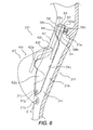
- the control device 110a has a brake bracket 30f contrived to be mounted to the handlebar 112, a brake lever 31f that is pivotally mounted to the brake bracket 30f, and a rear derailleur operating unit 32r that is mounted to the brake lever 31f.
- the brake bracket 30f is configured to be mounted to the curved section 112a of the handlebar 112. As shown in Figure 2 , a rear indexing position display device 119r indicates the indexing position of the rear derailleur 97r is provided on an upper frontal portion of the brake bracket 30f. A connector section 118 is provided inside the brake bracket 30f for connecting wires.
- the brake lever 31f is connected to the brake bracket 30f such that it can pivot freely about a lever shaft 33f arranged from left to right on a lower frontal portion of the brake bracket 30f.
- the brake lever 31f is connected to one end of a Bowden-type brake cable (not shown) on the inside of the brake bracket 30f.
- the other end of the brake cable is connected to the front brake 107f.
- the brake lever 31f has a lever operating part 31a that extends downward from a support portion where it is supported by the lever shaft 33f.
- the lever operating part 31a has a side wall 31d having a cut-away section 31c positioned in a middle portion along the lengthwise dimension of the lever operating part 31a.
- At least a portion of the rear derailleur operating unit 32r is arranged inside the cut-away section 31c.
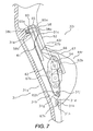
- a first guide section 31g is provided in a distal end portion of the lever operating part 31a.
- the first guide section 31g is configured to guide a first gearshift operating part 42r (described later) in a movement direction.
- a second guide section 31g is provided in a position of the lever operating part 31a that is farther toward the distal end of the lever operating part 31a than the first guide section 31g.
- the second guide section 31g is configured to guide the second gearshift operating part 44r in a movement direction.
- the first guide section 31g has a first guide shaft 31j that is supported in a cantilever fashion on a side wall 31i located on the opposite side of the lever operating part 31a as the side wall 31 d in which the cut-away section 31c is formed.
- the first guide shaft 31j is arranged to extend toward the side wall 31d.
- the second guide section 31h has a second guide shaft 31k arranged to be supported at both ends on the side walls 31d and 31i.
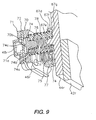
- the rear derailleur operating unit 32r comprises a first gearshift operating part 42r, a second gearshift operating part 44r, a first electrical switch 46r (see Figures 9 and 10 ) and a second electrical switch 48r (see Figures 9 and 10 ).
- the first gearshift operating part 42r is movable relative to the brake lever 31f.
- the second gearshift operating part 44r is movable relative to the brake lever 31f.
- the second gearshift operating part 44r is separate from the first gearshift operating part 42r.
- the first electrical switch 46r is operated with the first gearshift operating part 42r.
- the second electrical switch 48r is operated with the second gearshift operating part 44r.
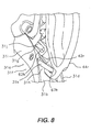
- the first and second gearshift operating parts 42r and 44r are pivotally mounted to a back surface 31b of the brake lever 31f.
- the first and second electrical switches 46r and 48r are mounted together in a switch mounting unit 54 on the side wall 31i of the brake lever 31f.
- the first gearshift operating part 42r is a generally plate-like member made of a synthetic resin material and is used to operate the rear derailleur 97r in the upshift direction. As shown in Figure 5 , the first gearshift operating part 42r can be pivoted from a first rest position P1 toward the middle of the handlebar 112, i.e., toward the inward side of the brake lever 31f in the direction indicated by the arrow A in Figure 5 . A first operating position P2, where the first electrical switch 46r is actuated, is located on the inward side of the first rest position P1. The first gearshift operating part 42r can be pivoted inwardly beyond the first operating position P2.
- the first gearshift operating part 42r has a first mounting part 60, a first arm part 61 and a first operating part 62.
- the first mounting part 60 is mounted on a pivot shaft 58.
- the first arm part 61 extends in a radial direction from the first mounting part 60.
- the first operating part 62 is arranged to intersect with a distal end portion of the first arm part 61 at an angle of approximately 90 degrees.
- a first support hole 60a is formed in the first mounting part 60 for the pivot shaft 58 to pass therethrough.
- the pivot shaft 58 is screwed into a threaded boss part 31e formed on the back surface 31b of the brake lever 31f.
- the pivot shaft 58 has a large diameter flange part 58a, a shaft part 58b and an externally threaded part 58c.
- the shaft part 58b fits snugly into the first support hole 60a.
- the externally threaded part 58c is formed on a distal end portion of the shaft part 58b.
- the externally threaded part 58c has a smaller diameter than the shaft part 58b.
- the first gearshift operating part 42r when the first gearshift operating part 42r is in the rest position P1, the first arm part 61 contacts an inward surface of the side wall 31d of the brake lever 31f at a portion where the cut-away section 31c is formed in the side wall 31d.
- the rest position P1 of the first gearshift operating part 42r i.e., the movement endpoint of the first gearshift operating part 42r in the outward direction, is determined by this contact.
- the first operating part 62 is arranged inside the cut-away section 31c of the side wall 31d of the brake lever 31f.
- the first operating part 62 has a first operating surface 62a that is formed as a rough surface.
- a first switch actuating part 62b configured to protrude rearward (leftward in Figure 6 ) in a semicircular shape and extend inward is formed on an intermediate portion along the lengthwise dimension of the first operating part 62.
- the switch actuating part 62b has a first spring holder 62c that protrudes inward, a second spring holder 62d configured to protrude in an annular shape around the outside of the first spring holder 62c, and a flat plate-like spring retainer 62e arranged and configured to join the two spring holders 62c and 62d.
- the first switch actuating part 62b abuts against one end of a first spring member 75 and one end of a third spring member 77 (described later).
- two pressing parts 62f and 62g configured such that they can press against the second gearshift operating part 44r are arranged on both lengthwise sides of the first switch actuating part 62b.
- the pressing parts 62f and 62g are formed thinner than other portions and are arranged and configured such that the second gearshift operating part 44r enters into the inside thereof (left side in Figure 7 ).
- an elongated hole 62h configured to be guided by the first guide shaft 31j of the brake lever 31f is formed in a distal end portion of the first operating part 62.
- the inward movement end position P3 ( Figure 11 ) of the first gearshift operating part 42r is determined by contact of an inward surface of a portion of the first operating part 62 where the elongated hole 62h is formed against a portion of the side wall 31i where the first guide shaft 31j is mounted.
- the second gearshift operating part 44r is a generally plate-like member made of a metal material.
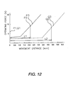
- the second gearshift operating part 44r is used to operate the rear derailleur 97r in the downshift direction. As shown in Figure 5 , the second gearshift operating part 44r can be pivoted from a second rest position Q1 toward the middle of the handlebar 112, i.e., toward the inward side of the brake lever 31f. A second operating position Q2 where the second electrical switch 48r is actuated is located on the inward side of the second rest position Q1. The second gearshift operating part 44r can be pivoted inwardly beyond the second operating position Q2. As shown in Figure 12 , the movement distance L1 from the first rest position P1 to the first operating position P2 is shorter than the distance L2 from the second rest position Q1 to the second operating position Q2.
- the second gearshift operating part 44r moves inward relative to the brake lever 31f together with the first gearshift operating part 42r. Conversely, when the second gearshift operating part 44r is moved inward relative to the brake lever 31f, the first gearshift operating part 42r does not move inward. Since the movement distance L1 of the first gearshift operating part 42r is shorter than the movement distance L2 of the second gearshift operating part 44r, the second electrical switch 48r is not actuated when the second gearshift operating part 44r moves inward as a result of the first gearshift operating part 42r being operated.
- the second gearshift operating part 44r has a second mounting part 65, a second arm part 66 and a second operating part 67.
- the second mounting part 65 is supported on the pivot shaft 58.
- the second arm part 66 extends in a radial direction from the second mounting part 65.
- the second operating part 67 is arranged to intersect with a distal end portion of the second arm part 66 at an angle of approximately 90 degrees.
- a second support hole 65a is formed in the second mounting part 65 for the pivot shaft 58 to pass there-through.
- the shaft part 58b of the pivot shaft 58 fits snugly into the support hole 65a. Since the first gearshift operating part 42r and the second gearshift operating part 44r are both pivotally mounted to the same pivot shaft 58, both members pivot about the same (single) axis.
- the second arm part 66 is in the same position as the first arm part 61 when the second gearshift operating part 44r is in the second rest position Q1.
- the second rest position Q1 is the movement endpoint of the second gearshift operating part 44r in the outward direction.
- the second arm part 66 extends in a radial direction from the second mounting part 65 in a position rearward of the first arm part 61.
- the second operating part 67 is arranged rearward (leftward in Figure 6 ) of the first operating part 62.
- a second operating surface 67a is formed on an outward face of the second operating part 67.
- the second operating surface 67a is a smooth surface without roughness or bumpiness such that it can be distinguished from the first operating surface 62a by the sense of touch (difference in texture).
- the gearshift operating parts 42r and 44r are both in the rest position P1 and Q1
- the second operating surface 67a is arranged in a different plane than the first operating surface 62a ( Figure 5 ). More specifically, the second operating surface 67a is arranged slightly further inward (leftward in Figure 5 ) than the first operating surface 62a.
- the first gearshift operating part 42r and the second gearshift operating part 44r can be distinguished based on both the difference in texture and the difference in arrangement, enabling unintended gear shift operations to be prevented in a reliable fashion.
- Pressure receiving parts 67b and 67c are provided on an upper end portion and an intermediate portion, respectively, along the lengthwise direction of the second operating part 67.
- the pressure receiving parts 67b and 67c arranged and configured to protrude in a forward direction (leftward in Figure 7 ).
- the pressure receiving parts 67b and 67c are provided in positions where they can contact the pressing parts 62f and 62g of the first operating part 62.
- the pressure receiving parts 67b and 67c are contacted and pressed by the pressing parts 62f and 62g when the first gearshift operating part 42r is pivoted from the first rest position P1.
- the second gearshift operating part 44r is pivoted in unison when the first gearshift operating part 42r is pivoted.
- a second switch actuating part 67d is formed on an inward surface of the pressure receiving part 67c and extends inwardly.
- the second switch actuating part 67d has a third spring holder 67e, a fourth spring holder 67f, and a flat plate-like spring retainer 67g.
- the third spring holder 67e protrudes inward.
- the fourth spring holder 67f protrudes in an annular shape around the outside of the third spring holder 67f.
- the flat plate-like spring retainer joins the two spring holders 67e and 67f.
- the second switch actuating part 67d abuts against one end of a second spring member 76 and one end of a fourth spring member 78 (described later). Between the pressure receiving parts 67b and 67c, the first switch actuating part 62b is deeply recessed in a substantially semicircular shape such that it can face opposite the first electrical switch 46r.
- an elongated hole 67h is formed in a distal end portion of the second operating part 67 to be guided by the second guide shaft 31k of the brake lever 31f.
- the inward movement end position Q3 of the second gearshift operating part 42r is determined by contact of an inward surface of a portion of the second operating part 67 where the elongated hole 67h is formed against a portion of the side wall 31i where the second guide shaft 31k is mounted.
- the switch mounting unit 54 is arranged in such a position as to face the first and second switch actuating parts 62b and 67d of the first and second operating parts 62 and 67 of the first and second gearshift operating parts 42r and 44r.
- the switch mounting unit 54 includes a switch bracket 70, a switch housing part 71, a water-resistant sheet packing 72 and first and second switch systems 73 and 74.
- the switch bracket 70 is screw fastened to the side wall 31 of the lever operating part 31a of the brake lever 31f.
- the switch housing part 71 separately encloses the first and second electrical switches 46r and 48r (which are tactile switches).
- the water-resistant sheet packing 72 seals the switch housing part 71.
- the first and second switch systems 73 and 74 are movably arranged on the switch bracket 70 with the sheet packing 72 sandwiched in between.
- the switch bracket 70 has an outside shape similar to that of the switch housing part 71.
- the switch housing 70 is, for example, screw fastened to the switch bracket 70.
- the switch housing part 71 has a housing recess 71a in which the first and second electrical switches 46r and 48r are housed.
- the first and second switch systems 73 and 74 are provided as a pair for the purpose of operating (actuating) the first and second electrical switches 46r and 48r, respectively.
- the first and second switch systems 73 and 74 are arranged in guide holes 70a and 70b, respectively, of the switch bracket 70 such that they can move toward and away from the first and second electrical switches 46r and 48r.
- the first switch system 73 comprises a rod-like part 73a, a large diameter flange part 73b and a switch pressing part 73c.
- the large diameter flange part 73b is formed integrally on one end of the rod-like part 73a.
- the switch pressing part 73c protrudes toward the sheet packing 72 from the center of the flange part 73b.
- the second switch system 74 comprises a rod-like part 74a, a large diameter flange part 74b and a switch pressing part 74c.
- the large diameter flange part 74b is formed integrally on one end of the rod-like part 74a.
- the switch pressing part 74c protrudes toward the sheet packing 72 from the center of the flange part 74b.
- a first spring member 75 is arranged between the flange part 73b of the first switch system 73 and the first switch actuating part 62b.
- a second spring member 76 is arranged between the flange part 74b of the second switch system 74 and the second switch actuating part 67d.
- the first and second spring members 75 and 76 are provided in the form of coil springs and function in operating the switches. Each of the first and second spring members 75 and 76 is arranged around the outside circumference of the corresponding rod like part 73a or 74a of the switch systems 73 and 74 in a free state in which it is neither compressed nor stretched.
- a third spring member 77 is arranged between the first switch actuating part 62b and the switch bracket 70, and a fourth spring member 78 is arranged between the second switch actuating part 67d and the switch bracket 70.
- the third and fourth spring members 77 and 78 are provided in the form of coil springs and arranged and configured to be positioned radially to the outside of the respective flange parts 73a and 74a.
- the third and fourth springs 77 and 78 exert forces serving to return the first and second gearshift operating parts 42r and 44r to the first and second rest positions P1 and Q1, respectively.
- the third spring member 77 is arranged around the outside of the first spring member 75 so as to be coaxial with respect to the first spring member and in a compressed state.
- the fourth spring member 78 is arranged around the outside of the second spring member 76 so as to be coaxial with respect to the second spring 76 and in a compressed state.
- the first spring member 75 is arranged between the first switch actuating part 62b and the flange part 73b such that a gap exists between the spring member 75 and the parts 62b and 73b.
- the second spring member 76 is arranged between the second switch actuating part 67d and the flange part 74b such that a gap exists. More specifically, as shown in Figure 12 , the first spring member 75 is arranged with a gap of 1.2 mm and the second spring member 76 is arranged with a gap of 3.4 mm such that the total movement distance includes a region of play in which the rate at which the operating force increases with respect to movement of the switch actuating part 62b or 67d is small.
- the first and second spring members 75 and 76 for actuating the switches have larger spring coefficients than the third and fourth spring members 77 and 78 for returning the switch actuating parts 62b and 67d to their original positions.
- the coil spring wire diameter of the first and second spring members 75 and 76 is larger and the number of windings is smaller than the third and fourth spring members 77 and 78. This aspect is not depicted accurately in Figure 9 .
- the free lengths of the first and third spring members 75 and 77 are shorter than the free lengths of the second and fourth spring members 76 and 78.
- first spring member 75 between the first gearshift operating part 42r and the first electrical switch 46r enables the first gearshift operating part 42r to be pivoted, i.e., over stroked, beyond the first operating position P2 after the first electrical switch 46r has been turned on by operating the first gearshift operating part 42r.
- second spring member 76 between the second gearshift operating part 44r and the second electrical switch 48r enables the second gearshift operating part 44r to be pivoted beyond the second operating position Q2 after the second electrical switch 48r has been turned on by operating the second gearshift operating part 44r.
- the third spring member 77 acts to return the first gearshift operating part 42r to the first rest position P1 after a gear shift operation
- the fourth spring member 78 acts to return the second gearshift operating part 44r to the second rest position Q1 after a gear shift operation.
- the control device 110b is mirror symmetrical to the control device 110a. As shown in Figure 3 , the control device 110b has a brake bracket 30r and a front derailleur operating unit 32f.
- the brake lever 31r operates the rear brake 107r, while the front derailleur operating unit 32f operates the front derailleur 97f so as to change gears.
- the front derailleur operating unit 32f comprises a first gearshift operating part 42f, a second gearshift operating part 44f, a first electrical switch 46f (see Figure 13 ) and a second electrical switch 48f (see Figure 13 ).
- the first gearshift operating part 42f is mounted to a back surface of the lever operating part 31a and movably connected to the brake lever 31r.
- the second gearshift operating part 44f is movably connected to the brake lever 31r and is a separate entity from the first gearshift operating part 42r.
- the first electrical switch 46f is operated with the first gearshift operating part 42f.
- the second electrical switch 48f is operated with the second gearshift operating part 44f.
- the second gearshift operating part 44r (or 44f) is pressed by the first gearshift operating part 42r (or 42f) such that the second gearshift operating part 44r (or 44f) pivots from the second rest position Q1 together with the first gearshift operating part 42r (or 42f).
- the switch pressing part 73c of the first switch system 73 presses the first electrical switch 46r (or 46f) through the sheet packing 72.
- the first spring member 75 begins to be compressed in addition to the third spring member 77 and the operating force increases rapidly.
- the change in the operating force of the first gearshift operating part 42r (or 42f) is indicated with a solid-line curve in Figure 12 .
- the spring force of the third spring member 77 that acts on the first gearshift operating part 42r and the first gearshift operating part 42r can be operated with a small force, i.e., with a degree of play.
- the operating force increases rapidly when the first spring member 75 starts to be compressed, and the first electrical switch 46r (or 46f) turns on when the first gearshift operating part 42r (or 42f) reaches the second operating position P2.
- the timing at which the first electrical switch 46r (or 46f) turns on after the first gearshift operating part 42r (or 42f) starts being operated can be readily recognized.
- the change in the operating force of the second gearshift operating part 44r (or 44f) is indicated with a broken-line curve in Figure 12 .
- the operating force of the second gearshift operating part 44r (or 44f) is small while only the fourth spring member 78 is compressed and increases rapidly when the second spring member 76 starts being compressed.
- the second operating position Q2 is reached after the rapid increase of the operating force occurs and the timing at which the second electrical switch 48r (or 48f) turns on after the second gearshift operating part 44r (or 44f) starts being operated can be readily recognized.
- the movement distance (operation stroke) L2 of the second gearshift operating part 44r to the operating position Q2 is longer than the movement distance L1 of the first gearshift operating part 42r and, likewise, the second gearshift operating part 44r has a longer range of play.
- the movement directions of each of the gearshift operating parts 42r and 44r can be set independently.
- both of the gearshift operating parts can be contrived such that the movement direction thereof is inward, i.e., toward the middle of the handlebar 112.
- two different types of gear change operation can be accomplished using only the ventral side of a finger tip.
- the second gearshift operating part 44r moves inward together with the first gearshift operating part 42r when the first gearshift operating part 42r is moved, the second gearshift operating part 44r can be moved in the same direction as the first gearshift operating part 42r. Consequently, even if the first gearshift operating part 42r is arranged closer to the finger tips (farther forward from the handlebar 112) than the second gearshift operating part 44r, the second gearshift operating part 44r does not impede the operation of the first gearshift operating part 42r. As a result, two difference types of gear change operation can be executed while preventing unintended gear change operations.
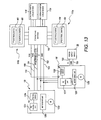
- the control devices 110a and 110b are connected to the rear derailleur 97r and the front derailleur 97f, respectively, with electrical wiring.
- the electric drive unit 18f of the front derailleur 97f includes a motor 125f, a motor drive unit 126f, a front derailleur control unit 127 (FD control unit) and a position sensor 128f.
- the motor 125f drives the front derailleur 97f.
- the motor drive unit 126f drives the motor 125f.
- the front derailleur control unit 127 controls the motor drive unit 126f based on a signal from the control device 110b.
- the position sensor 128f detects the indexing position of the front derailleur 97f.
- the electric drive unit 18r of the rear derailleur 97r includes a motor 125r, a motor drive unit 126r, a rear control unit 127 (RD control unit) and a position sensor 128r.
- the motor 125r drives the rear derailleur 97r.
- the motor drive unit 126r drives the motor 125r.
- the rear control unit 127 controls the motor drive unit 126r based on a signal from the control device 110a.
- the position sensor 128r detects the indexing position of the rear derailleur 97r.
- Each of the front and rear motor drive units 126f and 126r has a motor driver and a reduction unit configured to reduce the rotational speed of the respective motor 125f or 125r.
- Each of the front and rear control units 127f and 127r has a control circuit that includes a microcomputer having a memory unit and a processing unit and each is configured to use software to control the respective motor drive unit 126f or 126r, respectively, based on the signal outputted from the respective control device 110a or 110b.
- the front and rear position sensors 128f and 128r are configured to use, for example, a rotary encoder to detect the indexing position of the respective derailleur 97f or 97r.
- the power supply device 20 mounted to the front derailleur 97f delivers electric power through the connector section 118 to the deraille 97f and 97r, the control devices 110a and 110, and the front and rear indexing position display devices 119f and 119r. More specifically, direct current power supply voltage V of 6 to 8.4 volts is supplied from the power supply device 20 to the electric drive unit 18f of the front derailleur 97f through a power supply line 150 and a ground line 151. In turn, the power supply voltage V is supplied from the electric drive unit 18f to the electric drive unit 18r of the rear derailleur 97r through a power supply line 152 and a ground line 153.
- the power supply voltage V is supplied to the indexing position display devices 119f and 119r and the front and rear derailleur operating devices 110a and 110b through the connector section 118.
- the front and rear position sensors 128f and 128r issue indexing position signals FPOS and RPOS to the front and rear indexing position display devices 119f and 119r, respectively, through a position signal line 154 and the connector section 118.
- the indexing position display devices 119f and 119r display the indexing positions of the front and rear deraille 97f and 97r.
- indexing signals FDS and RDS are generated in response to operation of the control devices 110a and 110b and issued to the front and rear deraille 97f and 97r through the connector section 118 and indexing signal lines 155 and 156, respectively.
- the indexing signal line 156 for the indexing signal RDS is actually connected to the electric drive unit 18r through the electric drive unit 18f.
- the electric drive unit 18f of the front derailleur 97f is connected to the connector section 118 with a five-core wire passed through, for example, the down tube 102c, and the electric drive unit 18r is connected to the electric drive unit 18f with a four-core wire passed through, for example, the chain stay 102d. Therefore, it is acceptable to provide the electric drive unit 18f with a connector for connecting the five wires of the five-core wire collectively.
- the preceding embodiment presents a derailleur (externally mounted gear changer) as an example of a gear changer device
- the present invention can also be applied to a brake and gear changer operating device contrived to operate an internally installed gear changer device that has a plurality of indexing positions and can be electrically controlled.
- first gearshift operating part 42r and the second gearshift operating part 44r are connected to the brake lever 31f such that they pivot about the same pivot shaft 58, it is acceptable to connect them such that they pivot about separate pivot shafts. It is also acceptable to connect the gearshift operating parts 42r and 44r to the brake lever 31f such that they move in a fashion other than a pivoting fashion, e.g., a sliding fashion.
- the present invention can also be applied to a brake and gear changer operating device configured to execute indexing by two or more positions with a signal shift operation.
- the operating device can be configured to index the gear changer through a plurality of positions by executing a special shift operation, such as pressing the operating device for a longer period of time or double clicking the operating device.
- first and second gearshift operating parts 42r and 44r are mounted directly to the brake lever 31f. However, it is acceptable for the first and second gearshift operating parts 42r and 44r to be mounted to either the brake lever 31f or the brake bracket 30f with a separate mounting member.
- springs are used to operate the electrical switches in order to provide a degree of over stroke so as to improve the operating feel of the gear changer operating device.
- the gearshift operating part operates the electrical switch (i.e., turns it on and off) directly.
- the gap between the first gearshift operating part and the first electrical switch it is preferable for the gap between the second gearshift operating part and the second electrical switch to be smaller than the gap between the second gearshift operating part and the second electrical switch.
- step S2 when the electric power supply to the gear change control unit is turned on, the gear change control unit initializes itself in step S 1.
- Various variables and timers are set in the initialization.
- step S2 the control unit determines if both electrical switches 46r and 48r are on. When the movement distances of the two gearshift operating parts are the same, both of the electrical switches 46r and 48r will turn on when the first gearshift operating part 42r is operated.
- step S3 the control unit determines if only the second electrical switch 48r has turned on.
- step S4 the control unit determines if any other command, e.g., a display command, has been issued. When this determination is finished, the control unit returns to step S2.
Description
- This invention generally relates to a brake and gear shift device. More specifically, the present invention relates to a bicycle control device that is mounted to a handlebar of a bicycle for operating a braking device and for electrically operating an external gear changer apparatus.
- Bicycling is becoming an increasingly more popular form of recreation as well as a means of transportation. Moreover, bicycling has become a very popular competitive sport for both amateurs and professionals. Whether the bicycle is used for recreation, transportation or competition, the bicycle industry is constantly improving the various components of the bicycle. One component that has been extensively redesigned is the drive train.
- There are known bicycle gear changer devices that are electric powered and configured such that they can be controlled electrically so as to change among a plurality of gear positions. This kind of electric-powered gear changer device is operated with a gear shifter device that can be mounted to a brake bracket or a brake lever of a brake operating device (e.g., Japanese Laid-Open Patent Publication No.
2005-153865 - The conventional gear shifter device described above is contrived to execute two types of gear shifting, e.g., upshifting or downshifting, by pivoting the lever member in different directions from the operation start position. Consequently, in order to change gears, the lever member must be pivoted toward the middle or the outside of the handlebar from the operation start position with an index finger or middle finger of a rider's hand while the rider grips the brake bracket or a curved end portion of the handlebar. When the lever member is pivoted toward the middle of the handlebar in order to execute a gear shift operation, the gear shift operation is comparatively easy to execute because the lever member is pivoted using the ventral side (palm side) of the finger by pressing with the finger in a curved state. However, when the lever member is pivoted toward the outside of the handlebar, the gear shift operation is comparatively difficult to execute because the lever member is pivoted using the dorsal side (knuckle side) of the finger by pressing with the finger in an extended state. Such a solution is shown in the document
DE 4413610 , which discloses a bicycles control device according to the preamble ofclaim 1. - In view of the above, it will be apparent to those skilled in the art from this disclosure that there exists a need for an improved bicycle control device. This invention addresses this need in the art as well as other needs, which will become apparent to those skilled in the art from this disclosure.
- In order to avoid this difficulty, it is feasible to provide two gearshift operating parts that are pivotally arranged near a back surface of the brake lever and contrived to turn two electrical switches on and off in response to the pivot movement of the gearshift operating parts. Such an arrangement would enable two types of gear shift operations to be executed by operating two gear shift members in the same direction. However, when two different types of gear shift operation are accomplished by operating two gearshift operating parts in the same direction, one gearshift operating part sometimes gets in the way when the other gearshift operating part is operated. For example, if one gearshift operating part is arranged near the finger tips and the other gearshift operating part is arranged closer to the palm of the hand, then the gearshift operating part arranged closer to the palm of the hand impedes the operation of the gearshift operating part arranged near the finger tips because the operating finger must reach across the gear shift member arranged closer to the palm of the hand. There is also the possibility that the gearshift operating part arranged closer to the palm of the hand will be moved accidentally, causing an unintentional change of gears, when the rider is attempting to operating the gearshift operating part located near the fingertips. Consequently, the rider must be careful when shifting gears and it is troublesome to execute two different types of gear change operation.
- One object of the present invention is to provide is to provide a gear shifter device for operating an electric-powered gear changer device that enables two different types of gear shift operation to be executed easily while preventing the occurrence of unintended gear shifting.
- In accordance with a first aspect of the present invention, a bicycle control device is provided that basically comprises a brake bracket, a brake lever, a first gearshift operating part, a second gearshift operating part, a first electrical switch, and a second electrical switch. The brake bracket is configured to be mounted to a handlebar. The brake lever is pivotally mounted to the brake bracket. The first gearshift operating part is movable relative to the brake lever. The second gearshift operating part is separate from the first gearshift operating part and movable relative to the brake lever. The first electrical switch is operated with the first gearshift operating part. The second electrical switch is operated with the second gearshift operating part. The second gearshift operating part is arranged such that when the first gearshift operating part is moved relative to the brake lever, the second gearshift operating part moves relative to the brake lever along with the first gearshift operating part.
- With this bicycle control device, a brake can be operated by pivoting the brake lever. Additionally, a gear change operation can be executed by operating the first gearshift operating part so as to turn the first electrical switch on and off and a second gear change operation can be executed by operating the second gearshift operating part so as to turn the second electrical switch on and off. Since the gear change operations are executed with two separate gearshift operating parts, the movement directions of the gearshift operating parts can be set independently from each other. For example, both of the gearshift operating parts can be contrived such that the movement direction thereof is inward toward the middle of the handlebar. Thus, two different types of gear change operation can be accomplished using only the ventral side of a finger tip. Furthermore, since the second gearshift operating part moves together with the first gearshift operating part when the first gearshift operating part is moved, the second gearshift operating part can be moved in the same direction as the first gearshift operating part. Consequently, the second gearshift operating part does not impede the operation of the first gearshift operating part. Since the second gearshift operating part moves together with the first gearshift operating part, the second gearshift operating part is not likely to be operated unintentionally when the first gearshift operating part is operated. As a result, two types of gear change operation can be accomplished using a finger tip while preventing the occurrence of unintended gear change operations.
- A bicycle control device in accordance with a second aspect of the present invention is the device in accordance with the first aspect, wherein the first gearshift operating part is arranged such that when the second gearshift operating part is moved relative to the brake lever, the first gearshift operating part does not move relative to the brake lever. With this aspect of the invention, even if the second gearshift operating part is arranged closer to the palm (closer to the handlebar) than the first gearshift operating part, the force required to operate the second gearshift operating part is lightened because only the second gearshift operating part moves when the second gearshift operating part is operated.
- A bicycle control device in accordance with a third aspect of the present invention is the device in accordance with the first or second aspect, wherein the first gearshift operating part has a contacting part that presses against the second gearshift operating part when the first gearshift operating part is moved relative to the brake lever. With this aspect of the invention, the second gearshift operating part can be moved easily when the first gearshift operating part is moved because the contacting part presses against the second gearshift operating part and moves it.
- A bicycle control device in accordance with a fourth aspect of the present invention is the device in accordance with any one of the first to third aspects, wherein the first gearshift operating part is movable from a first rest position to a first operating position by a first movement distance where the first electrical switch is actuated, the second gearshift operating part is movable from a second rest position to a second operating position by a second movement distance where the second electrical switch is actuated, and the first movement distance of the first gearshift operating part is shorter than the second movement distance of the second gearshift operating part. With this aspect of the invention, since the distance through which the second gearshift operating part must move before the corresponding electrical switch is actuated is larger than the distance through which the first gearshift operating part must move, the second gearshift operating part does not reach the second operating position when it moves together with the first gearshift operating part during operation of the first gearshift operating part. As a result, unintentional actuation of the second electrical switch can be prevented with a simple structure.
- A bicycle control device in accordance with a fifth aspect of the present invention is the device in accordance with the fourth aspect that further comprises: a first spring member for is provided between the first gearshift operating part and the first electrical switch actuating the first electrical switch; and a second spring member is provided between the second gearshift operating part and the second electrical switch for actuating the second electrical switch, with a free length of the first spring member being shorter than a free length of the second spring member.
- When first gearshift operating part is moved from the rest position, the first spring member is compressed and the spring force thereof increases. The first electrical switch is actuated when the spring force becomes sufficient to actuate the first electrical switch. Similarly, when second gearshift operating part is moved from the second rest position, the second spring member is compressed and the spring force thereof increases. The second electrical switch is actuated when the spring force becomes sufficient to actuate the second electrical switch. Thus, the movement distances through which the first and second gearshift operating parts move from the first and second rest positions to the first and second operating positions, respectively, can be adjusted as desired with a simple structure by simply using first and second spring members having different free lengths.
- A bicycle control device in accordance with a sixth aspect of the present invention is the device in accordance with the fifth aspect that further comprises a third spring member is provided between the first gearshift operating part and the first electrical switch provided in a free state for returning the first gearshift operating part to the first rest position; and a fourth spring member is provided between the second gearshift operating part and the second electrical switch for returning the second gearshift operating part to the second rest position; with the first and second spring members being provided in a free state, the third and fourth spring members being provided in a compressed state and a spring constant of the third and fourth spring members being smaller than a spring constant of the first and second spring members. Since the first and second spring members are provided in a free state, initially, the comparatively small spring forces of the third and fourth spring members are acting against the first and second gearshift operating parts. As the first or second spring member is compressed, a larger spring force acts on the first or second gearshift operating part. As a result, the spring force increases at an intermediate position during operation of the gearshift operating part, making it easier for the rider to recognize that the gearshift operating part is drawing near to the first or second operating position.
- A bicycle control device in accordance with a seventh aspect of the present invention is the device in accordance with any one of the first to sixth aspects, wherein: the first gear shift member has a first operating surface for executing a gear shift operation; and the second gearshift operating part has a second operating surface arranged in close proximity to the first operating surface. In this aspect of the invention, it is easier to operate the two operating surfaces with only a finger tip because the first and second gearshift operating parts are arranged such that the first and second operating surfaces are close to each other.
- A bicycle control device in accordance with an eighth aspect of the present invention is the device in accordance with the seventh aspect, wherein the first operating surface has a first texture that is different from a second texture of the second operating surface. With this aspect of the invention, the difference between the first gearshift operating part and the second gearshift operating part can be recognized by the sense of touch of a finger tip. As a result, unintended gear change operations are reduced and two types of gear change operation are easier to execute.
- A bicycle control device in accordance with a ninth aspect of the present invention is the device in accordance with the seventh aspect, wherein one of the first and second operating surfaces is a roughened surface and the other is a smooth surface. With this aspect of the invention, the difference feeling to the touch can be made more obvious based on the difference in texture between the roughened surface and the smooth surface. Additionally, if a flexible material is used, the movement distance can be increased by utilizing the bending (flexing) of the material.
- A bicycle control device in accordance with a tenth aspect of the present invention is the device in accordance with the eighth or ninth aspect, wherein a hardness of the first operating surface is different from a hardness of the second operating surface. With this aspect of the invention, the difference feeling to the touch can be made more obvious based on the difference in hardness of the two gearshift operating parts.
- A bicycle control device in accordance with an eleventh aspect of the present invention is the device in accordance with any one of the first to tenth aspects, wherein the brake lever has a side wall having a cut-away portion; and at least a portion of the first gearshift operating part is arranged inside the cut-away portion. With this aspect of the invention, since at least a portion of the first gearshift operating part is arranged inside the cut-away portion formed in a side wall of the brake lever, the first gearshift operating part can be moved easily while keeping one's figure on the brake lever.
- A bicycle control device in accordance with a twelfth aspect of the present invention is the device in accordance with any one of the first to eleventh aspects, wherein the first and second gearshift operating parts are pivotally with respect to the brake lever with the first and second gearshift operating parts being pivoted in same directions with respect to the brake lever when a gear shift operation is performed by each of the first and second gearshift operating parts. With this aspect of the present invention, the first and second gearshift operating parts are easier to operate with a finger tip because both the first and second gearshift operating parts are contrived to pivot and the pivot direction of both members is the same.
- A bicycle control device in accordance with a thirteenth aspect of the present invention is the device in accordance with the twelfth aspect, wherein the first and second gearshift operating parts are pivotally connected to the brake lever about a single pivot axis. With this aspect of the invention, since the first and second gearshift operating parts are connected to the brake lever such that they both pivot about the same axis, both gearshift operating parts can be connected with a single pivot shaft and the structure with which the first and second gearshift operating parts are connected to the brake lever can be simplified.
- A bicycle control device in accordance with a fourteenth aspect of the present invention is the device in accordance with any one of the first to thirteenth aspects, wherein the brake lever has a guide section that guides at least one of the first and second gearshift operating parts in a movement direction. With this aspect of the invention, when the first and second gearshift operating parts are moved in order to change gears, at least one of the first and second gearshift operating parts is guided by the guide section of the brake lever. As a result, the guided gearshift operating part(s) moves smoothly, making the gear shift member even easier to operate with a finger tip.
- With the present invention, since the gear change operations are executed with two separate gearshift operating parts, the movement directions of the gearshift operating parts can be set independently from each other. For example, both of the gearshift operating parts can be contrived such that the movement direction thereof is inward toward the middle of the handlebar. Thus, two different types of gear change operation can be accomplished using only the ventral side of a finger tip.
- Furthermore, since the second gearshift operating part moves together with the first gearshift operating part when the first gearshift operating part is moved, the second gearshift operating part can be moved in the same direction as the first gearshift operating part. Consequently, even if the first gearshift operating part is arranged closer to the finger tips (farther from the handlebar) than the second gearshift operating part, the second gearshift operating part does not impede the operation of the first gearshift operating part. As a result, two difference types of gear change operation can be executed while preventing unintended gear change operations.
- These and other objects, features, aspects and advantages of the present invention will become apparent to those skilled in the art from the following detailed description, which, taken in conjunction with the annexed drawings, discloses a preferred embodiment of the present invention.
- Referring now to the attached drawings which form a part of this original disclosure:
-
Figure 1 is a side elevational view of a bicycle equipped with a pair of bicycle (brake/derailleur) control devices in accordance with one embodiment of the present invention; -
Figure 2 is an enlarged side elevational view of the bicycle (brake/derailleur) control device for operating the front brake of the bicycle; -
Figure 3 is an enlarged side elevational view of the bicycle (brake/derailleur) control device for operating the rear brake of the bicycle; -
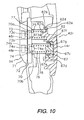
Figure 4 is an enlarged rear perspective view of the rear derailleur operating unit on the lever operating part of the front brake lever; -
Figure 5 is an enlarged rear elevational view of the rear derailleur operating unit on the lever operating part of the front brake lever; -
Figure 6 is a cross sectional view of leftward facing cross section of the rear derailleur operating unit on the lever operating part of the front brake lever; -
Figure 7 is a cross sectional view of rightward facing cross section of the rear derailleur operating unit on the lever operating part of the front brake lever; -
Figure 8 is an enlarged perspective view of a distal end portion of the gearshift operating part; -
Figure 9 is a perspective cross sectional view of a switch mounting unit; -
Figure 10 is a cross sectional view of a vicinity of a switch mounting unit; -
Figure 11 is a series of rear views illustrating the operation of a gearshift operating part; -
Figure 12 is a graph plotting the operating force versus the movement distance for the gearshift operating parts; -
Figure 13 is a block diagram showing the constituent components of a gear change control system; and -
Figure 14 is a control flowchart for another embodiment. - Selected embodiments of the present invention will now be explained with reference to the drawings. It will be apparent to those skilled in the art from this disclosure that the following descriptions of the embodiments of the present invention are provided for illustration only and not for the purpose of limiting the invention as defined by the appended claims and their equivalents.
- Referring initially to
Figure 1 , abicycle 101 is illustrated in accordance with a first embodiment of the present invention.Figure 1 shows abicycle 101 1 in which an embodiment of the present invention is employed. Thebicycle 101 is a "road racer" (racing style road bike). Thebicycle 101 basically includes a diamond-shapedframe 102 having afront fork 98, ahandlebar unit 104 fastened to thefront fork 98, adrive unit 105, afront wheel 106f mounted to thefront fork 98 and arear wheel 106r mounted to a rear portion of theframe 102. Thedrive unit 105 basically includes achain 95, a crank 96 on which pedals PD are mounted, a motorizedfront derailleur 97f, a motorizedrear derailleur 97r, afront sprocket cluster 99f, and arear sprocket cluster 99r. The rear andfront derailleurs bicycle 101 also includes afront brake device 107f, arear brake device 107r, and a pair (right and left)control devices right control device 110a is configured to control therear derailleur 97r and thefront brake device 107f. Theleft control device 110b is configured to control thefront derailleur 97f and thefront brake device 107r. - The
handlebar unit 104 comprises ahandlebar stem 111 and ahandlebar 112 that is fitted into and fastened to the upper end of thehandlebar stem 111 as shown inFigure 1 . Thehandlebar stem 111 is fitted into and fastened to the upper part of thefront fork 98. Thehandlebar 112 is a drop-type handlebar having U-shapedcurved sections curved sections control devices handlebar 112 for operating the rear andfront derailleurs rear devices control device 110a is arranged on the right-hand end of thehandlebar 112 when thebicycle 101 is viewed from the rear. Thecontrol device 110b is arranged on the left-hand end. - The
control devices rear brake devices control devices front derailleurs cycle computer 114 is configured to display speed and traveled distance of the bicycle is arranged in a middle portion of thehandlebar 112. Thus, thecycle computer 114 functions as a speed indicator. - The front derailleur (FD) 97f is mounted to a
seat tube 102a of theframe 102. Thefront derailleur 97f is configured such that it can be controlled electrically. Thefront derailleur 97f is an electrically driven derailleur that is configured to move its chain guide to either of indexing positions F1 or F2 in response to a gear shifting operation of thecontrol device 110b so that thechain 95 is moved onto the corresponding sprocket of thefront sprocket cluster 99f. Thefront derailleur 97f basically includes a mountingmember 12f, achain guide 14f and a four-point linkage mechanism 16f. The mountingmember 12f is fastened to theseat tube 102a of theframe 102. Thechain guide 14f is configured and arranged such that it can be moved toward and away from the mountingmember 12f. Thechain guide 14f guides thechain 95 by moving between the first position SP1 and the second position SP2. The four-point linkage mechanism 16f is arranged to connect thechain guide 14f to the mountingmember 12f. Thefront derailleur 97f is operated with anelectric drive unit 18f that is arranged and configured to drive the four-point linkage mechanism 16f in such a manner as to move thechain guide 14f. - The rear derailleur (RD) 97r is configured such that it can be controlled electrically. The rear derailleur (RD) 97r is mounted to a rear portion of a
chain stay 102d of theframe 102. Therear derailleur 97r f is an electrically driven derailleur that is configured to move its chain guide to any one of ten indexing positions R1 or R10 in response to a gear shifting operation of thecontrol device 110a so that thechain 95 is moved onto the corresponding sprocket therear sprocket cluster 99r. Therear derailleur 97r basically includes a mountingmember 12r, achain guide 14r and a four-point linkage mechanism 16r. The mountingmember 12r is fastened to the rear portion of thechain stay 102d of theframe 102. Thechain guide 14r is configured and arranged such that it can be moved relative to the mountingmember 12r. The four-point linkage mechanism 16r is arranged to connect thechain guide 14r to the mountingmember 12f. - The
rear derailleur 97r is operated with anelectric drive unit 18r that is arranged and configured to drive the four-point linkage mechanism 16r in such a manner as to move thechain guide 14r. Apower supply device 20 is mounted to the front derailleur 97. Thepower supply device 20 serves as a power source for the front andrear derailleurs - The
front sprocket cluster 99f has a plurality of (e.g., two) sprockets that are arranged along the axial direction of the crank axle and have different tooth counts. The two sprockets are arranged to be aligned with the indexing positions F1 and F2. Therear sprocket cluster 99f has a plurality of (e.g., ten) sprockets that are arranged along the axial direction of the hub axle of therear wheel 106r, and each sprocket has a different tooth count. The ten sprockets are arranged to be aligned with the indexing positions R1 andR 10. - The sprockets of the
front sprocket cluster 99f are arranged such that the sprocket located on the inward side and corresponding to the indexing position F1 is a low sprocket and the sprocket located on the outward side and corresponding to the indexing position F2 is a top sprocket having a larger tooth count than the low sprocket. The sprockets of therear sprocket cluster 99r are arranged such that the innermost sprocket corresponding to the indexing position R1 is a low sprocket having the most teeth and the outermost sprocket corresponding to theindexing position R 10 is a top sprocket having the smallest number of teeth. Thus, the tooth counts of the sprockets decrease as one moves from the inside toward the outside of the cluster. - Since the
control devices control device 110a, which is arranged on the right side of thehandlebar 112. In the following explanations, the term "inward" refers to a direction oriented toward the middle of thehandlebar 112 from one end or the other of thehandlebar 112, and "outward" refers to a direction oriented toward an end of thehandlebar 112 from the middle of thehandlebar 112. - As shown in
Figure 2 , thecontrol device 110a is mounted to thecurved section 112a of thehandlebar 112. Thecontrol device 110a has abrake bracket 30f contrived to be mounted to thehandlebar 112, abrake lever 31f that is pivotally mounted to thebrake bracket 30f, and a rearderailleur operating unit 32r that is mounted to thebrake lever 31f. - The
brake bracket 30f is configured to be mounted to thecurved section 112a of thehandlebar 112. As shown inFigure 2 , a rear indexingposition display device 119r indicates the indexing position of therear derailleur 97r is provided on an upper frontal portion of thebrake bracket 30f. Aconnector section 118 is provided inside thebrake bracket 30f for connecting wires. - The
brake lever 31f is connected to thebrake bracket 30f such that it can pivot freely about alever shaft 33f arranged from left to right on a lower frontal portion of thebrake bracket 30f. Thebrake lever 31f is connected to one end of a Bowden-type brake cable (not shown) on the inside of thebrake bracket 30f. The other end of the brake cable is connected to thefront brake 107f. Thebrake lever 31f has alever operating part 31a that extends downward from a support portion where it is supported by thelever shaft 33f. Thelever operating part 31a has aside wall 31d having a cut-awaysection 31c positioned in a middle portion along the lengthwise dimension of thelever operating part 31a. At least a portion of the rearderailleur operating unit 32r is arranged inside the cut-awaysection 31c. Afirst guide section 31g is provided in a distal end portion of thelever operating part 31a. Thefirst guide section 31g is configured to guide a firstgearshift operating part 42r (described later) in a movement direction. Asecond guide section 31g is provided in a position of thelever operating part 31a that is farther toward the distal end of thelever operating part 31a than thefirst guide section 31g. Thesecond guide section 31g is configured to guide the secondgearshift operating part 44r in a movement direction. As shown inFigure 8 , thefirst guide section 31g has afirst guide shaft 31j that is supported in a cantilever fashion on aside wall 31i located on the opposite side of thelever operating part 31a as theside wall 31 d in which the cut-awaysection 31c is formed. Thefirst guide shaft 31j is arranged to extend toward theside wall 31d. Thesecond guide section 31h has asecond guide shaft 31k arranged to be supported at both ends on theside walls - As shown in
Figures 4 to 11 , the rearderailleur operating unit 32r comprises a firstgearshift operating part 42r, a secondgearshift operating part 44r, a firstelectrical switch 46r (seeFigures 9 and10 ) and a secondelectrical switch 48r (seeFigures 9 and10 ). The firstgearshift operating part 42r is movable relative to thebrake lever 31f. The secondgearshift operating part 44r is movable relative to thebrake lever 31f. The secondgearshift operating part 44r is separate from the firstgearshift operating part 42r. The firstelectrical switch 46r is operated with the firstgearshift operating part 42r. The secondelectrical switch 48r is operated with the secondgearshift operating part 44r. The first and secondgearshift operating parts back surface 31b of thebrake lever 31f. The first and secondelectrical switches switch mounting unit 54 on theside wall 31i of thebrake lever 31f. - The first
gearshift operating part 42r is a generally plate-like member made of a synthetic resin material and is used to operate therear derailleur 97r in the upshift direction. As shown inFigure 5 , the firstgearshift operating part 42r can be pivoted from a first rest position P1 toward the middle of thehandlebar 112, i.e., toward the inward side of thebrake lever 31f in the direction indicated by the arrow A inFigure 5 . A first operating position P2, where the firstelectrical switch 46r is actuated, is located on the inward side of the first rest position P1. The firstgearshift operating part 42r can be pivoted inwardly beyond the first operating position P2. - As shown in
Figures 6 and7 , the firstgearshift operating part 42r has a first mountingpart 60, afirst arm part 61 and afirst operating part 62. The first mountingpart 60 is mounted on apivot shaft 58. Thefirst arm part 61 extends in a radial direction from the first mountingpart 60. Thefirst operating part 62 is arranged to intersect with a distal end portion of thefirst arm part 61 at an angle of approximately 90 degrees. Afirst support hole 60a is formed in the first mountingpart 60 for thepivot shaft 58 to pass therethrough. Thepivot shaft 58 is screwed into a threadedboss part 31e formed on theback surface 31b of thebrake lever 31f. Thepivot shaft 58 has a largediameter flange part 58a, ashaft part 58b and an externally threadedpart 58c. Theshaft part 58b fits snugly into thefirst support hole 60a. The externally threadedpart 58c is formed on a distal end portion of theshaft part 58b. The externally threadedpart 58c has a smaller diameter than theshaft part 58b. - As shown in
Figure 5 , when the firstgearshift operating part 42r is in the rest position P1, thefirst arm part 61 contacts an inward surface of theside wall 31d of thebrake lever 31f at a portion where the cut-awaysection 31c is formed in theside wall 31d. Thus, the rest position P1 of the firstgearshift operating part 42r, i.e., the movement endpoint of the firstgearshift operating part 42r in the outward direction, is determined by this contact. - As shown in
Figures 6 and7 , thefirst operating part 62 is arranged inside the cut-awaysection 31c of theside wall 31d of thebrake lever 31f. Thefirst operating part 62 has afirst operating surface 62a that is formed as a rough surface. A firstswitch actuating part 62b configured to protrude rearward (leftward inFigure 6 ) in a semicircular shape and extend inward is formed on an intermediate portion along the lengthwise dimension of thefirst operating part 62. As shown inFigure 10 , theswitch actuating part 62b has a first spring holder 62c that protrudes inward, asecond spring holder 62d configured to protrude in an annular shape around the outside of the first spring holder 62c, and a flat plate-like spring retainer 62e arranged and configured to join the twospring holders 62c and 62d. The firstswitch actuating part 62b abuts against one end of afirst spring member 75 and one end of a third spring member 77 (described later). - As shown in
Figures 5 to 7 , twopressing parts gearshift operating part 44r are arranged on both lengthwise sides of the firstswitch actuating part 62b. Thepressing parts gearshift operating part 44r enters into the inside thereof (left side inFigure 7 ). - As shown in
Figure 8 , anelongated hole 62h configured to be guided by thefirst guide shaft 31j of thebrake lever 31f is formed in a distal end portion of thefirst operating part 62. The inward movement end position P3 (Figure 11 ) of the firstgearshift operating part 42r is determined by contact of an inward surface of a portion of thefirst operating part 62 where theelongated hole 62h is formed against a portion of theside wall 31i where thefirst guide shaft 31j is mounted. - The second
gearshift operating part 44r is a generally plate-like member made of a metal material. The secondgearshift operating part 44r is used to operate therear derailleur 97r in the downshift direction. As shown inFigure 5 , the secondgearshift operating part 44r can be pivoted from a second rest position Q1 toward the middle of thehandlebar 112, i.e., toward the inward side of thebrake lever 31f. A second operating position Q2 where the secondelectrical switch 48r is actuated is located on the inward side of the second rest position Q1. The secondgearshift operating part 44r can be pivoted inwardly beyond the second operating position Q2. As shown inFigure 12 , the movement distance L1 from the first rest position P1 to the first operating position P2 is shorter than the distance L2 from the second rest position Q1 to the second operating position Q2. - When the first
gearshift operating part 42r is moved inward relative to thebrake lever 31f, the secondgearshift operating part 44r moves inward relative to thebrake lever 31f together with the firstgearshift operating part 42r. Conversely, when the secondgearshift operating part 44r is moved inward relative to thebrake lever 31f, the firstgearshift operating part 42r does not move inward. Since the movement distance L1 of the firstgearshift operating part 42r is shorter than the movement distance L2 of the secondgearshift operating part 44r, the secondelectrical switch 48r is not actuated when the secondgearshift operating part 44r moves inward as a result of the firstgearshift operating part 42r being operated. - The second
gearshift operating part 44r has a second mountingpart 65, asecond arm part 66 and asecond operating part 67. The second mountingpart 65 is supported on thepivot shaft 58. Thesecond arm part 66 extends in a radial direction from the second mountingpart 65. Thesecond operating part 67 is arranged to intersect with a distal end portion of thesecond arm part 66 at an angle of approximately 90 degrees. - A
second support hole 65a is formed in the second mountingpart 65 for thepivot shaft 58 to pass there-through. Theshaft part 58b of thepivot shaft 58 fits snugly into thesupport hole 65a. Since the firstgearshift operating part 42r and the secondgearshift operating part 44r are both pivotally mounted to thesame pivot shaft 58, both members pivot about the same (single) axis. - As shown in
Figure 5 , thesecond arm part 66 is in the same position as thefirst arm part 61 when the secondgearshift operating part 44r is in the second rest position Q1. Thus, the second rest position Q1 is the movement endpoint of the secondgearshift operating part 44r in the outward direction. Thesecond arm part 66 extends in a radial direction from the second mountingpart 65 in a position rearward of thefirst arm part 61. - As shown in
Figures 5 to 7 , thesecond operating part 67 is arranged rearward (leftward inFigure 6 ) of thefirst operating part 62. Asecond operating surface 67a is formed on an outward face of thesecond operating part 67. Thesecond operating surface 67a is a smooth surface without roughness or bumpiness such that it can be distinguished from thefirst operating surface 62a by the sense of touch (difference in texture). When thegearshift operating parts second operating surface 67a is arranged in a different plane than thefirst operating surface 62a (Figure 5 ). More specifically, thesecond operating surface 67a is arranged slightly further inward (leftward inFigure 5 ) than thefirst operating surface 62a. Thus, the firstgearshift operating part 42r and the secondgearshift operating part 44r can be distinguished based on both the difference in texture and the difference in arrangement, enabling unintended gear shift operations to be prevented in a reliable fashion. -
Pressure receiving parts second operating part 67. Thepressure receiving parts Figure 7 ). Thepressure receiving parts pressing parts first operating part 62. Thepressure receiving parts pressing parts gearshift operating part 42r is pivoted from the first rest position P1. As a result, the secondgearshift operating part 44r is pivoted in unison when the firstgearshift operating part 42r is pivoted. - As shown in
Figure 10 , a secondswitch actuating part 67d is formed on an inward surface of thepressure receiving part 67c and extends inwardly. Similarly to the firstswitch actuating part 62b, the secondswitch actuating part 67d has athird spring holder 67e, afourth spring holder 67f, and a flat plate-like spring retainer 67g. Thethird spring holder 67e protrudes inward. Thefourth spring holder 67f protrudes in an annular shape around the outside of thethird spring holder 67f. The flat plate-like spring retainer joins the twospring holders switch actuating part 67d abuts against one end of asecond spring member 76 and one end of a fourth spring member 78 (described later). Between thepressure receiving parts switch actuating part 62b is deeply recessed in a substantially semicircular shape such that it can face opposite the firstelectrical switch 46r. - As shown in
Figure 8 , anelongated hole 67h is formed in a distal end portion of thesecond operating part 67 to be guided by thesecond guide shaft 31k of thebrake lever 31f. The inward movement end position Q3 of the secondgearshift operating part 42r is determined by contact of an inward surface of a portion of thesecond operating part 67 where theelongated hole 67h is formed against a portion of theside wall 31i where thesecond guide shaft 31k is mounted. - As shown in
Figures 9 and10 , theswitch mounting unit 54 is arranged in such a position as to face the first and secondswitch actuating parts second operating parts gearshift operating parts switch mounting unit 54 includes aswitch bracket 70, aswitch housing part 71, a water-resistant sheet packing 72 and first andsecond switch systems switch bracket 70 is screw fastened to the side wall 31 of thelever operating part 31a of thebrake lever 31f. Theswitch housing part 71 separately encloses the first and secondelectrical switches switch housing part 71. The first andsecond switch systems switch bracket 70 with the sheet packing 72 sandwiched in between. Theswitch bracket 70 has an outside shape similar to that of theswitch housing part 71. Theswitch housing 70 is, for example, screw fastened to theswitch bracket 70. Theswitch housing part 71 has a housing recess 71a in which the first and secondelectrical switches - The first and
second switch systems electrical switches second switch systems guide holes switch bracket 70 such that they can move toward and away from the first and secondelectrical switches first switch system 73 comprises a rod-like part 73a, a largediameter flange part 73b and aswitch pressing part 73c. The largediameter flange part 73b is formed integrally on one end of the rod-like part 73a. Theswitch pressing part 73c protrudes toward the sheet packing 72 from the center of theflange part 73b. Similarly, thesecond switch system 74 comprises a rod-like part 74a, a largediameter flange part 74b and aswitch pressing part 74c. The largediameter flange part 74b is formed integrally on one end of the rod-like part 74a. Theswitch pressing part 74c protrudes toward the sheet packing 72 from the center of theflange part 74b. Afirst spring member 75 is arranged between theflange part 73b of thefirst switch system 73 and the firstswitch actuating part 62b. Asecond spring member 76 is arranged between theflange part 74b of thesecond switch system 74 and the secondswitch actuating part 67d. The first andsecond spring members second spring members part 73a or 74a of theswitch systems third spring member 77 is arranged between the firstswitch actuating part 62b and theswitch bracket 70, and afourth spring member 78 is arranged between the secondswitch actuating part 67d and theswitch bracket 70. The third andfourth spring members respective flange parts 73a and 74a. The third andfourth springs gearshift operating parts third spring member 77 is arranged around the outside of thefirst spring member 75 so as to be coaxial with respect to the first spring member and in a compressed state. Similarly, thefourth spring member 78 is arranged around the outside of thesecond spring member 76 so as to be coaxial with respect to thesecond spring 76 and in a compressed state. Thefirst spring member 75 is arranged between the firstswitch actuating part 62b and theflange part 73b such that a gap exists between thespring member 75 and theparts second spring member 76 is arranged between the secondswitch actuating part 67d and theflange part 74b such that a gap exists. More specifically, as shown inFigure 12 , thefirst spring member 75 is arranged with a gap of 1.2 mm and thesecond spring member 76 is arranged with a gap of 3.4 mm such that the total movement distance includes a region of play in which the rate at which the operating force increases with respect to movement of theswitch actuating part - The first and
second spring members fourth spring members switch actuating parts second spring members fourth spring members Figure 9 . The free lengths of the first andthird spring members fourth spring members - The existence of
first spring member 75 between the firstgearshift operating part 42r and the firstelectrical switch 46r enables the firstgearshift operating part 42r to be pivoted, i.e., over stroked, beyond the first operating position P2 after the firstelectrical switch 46r has been turned on by operating the firstgearshift operating part 42r. Similarly, the existence of thesecond spring member 76 between the secondgearshift operating part 44r and the secondelectrical switch 48r enables the secondgearshift operating part 44r to be pivoted beyond the second operating position Q2 after the secondelectrical switch 48r has been turned on by operating the secondgearshift operating part 44r. As a result, the gear shift operation can be executed comfortably without the feeling of a sudden stop of the pivot motion. Thethird spring member 77 acts to return the firstgearshift operating part 42r to the first rest position P1 after a gear shift operation, and thefourth spring member 78 acts to return the secondgearshift operating part 44r to the second rest position Q1 after a gear shift operation. In order to provide a difference in feeling between operation of the firstgearshift operating part 42r during upshifting and operation of the secondgearshift operating part 44r during downshifting, it is acceptable to configure thethird spring member 77 for returning the firstgearshift operating part 42r to have a larger spring constant (stronger spring force) than thefourth spring member 78 for returning the secondgearshift operating part 44r. - The
control device 110b is mirror symmetrical to thecontrol device 110a. As shown inFigure 3 , thecontrol device 110b has abrake bracket 30r and a frontderailleur operating unit 32f. Thebrake lever 31r operates therear brake 107r, while the frontderailleur operating unit 32f operates thefront derailleur 97f so as to change gears. - Similarly to the rear
derailleur operating unit 32r, the frontderailleur operating unit 32f comprises a firstgearshift operating part 42f, a secondgearshift operating part 44f, a firstelectrical switch 46f (seeFigure 13 ) and a secondelectrical switch 48f (seeFigure 13 ). The firstgearshift operating part 42f is mounted to a back surface of thelever operating part 31a and movably connected to thebrake lever 31r. The secondgearshift operating part 44f is movably connected to thebrake lever 31r and is a separate entity from the firstgearshift operating part 42r. The firstelectrical switch 46f is operated with the firstgearshift operating part 42f. The secondelectrical switch 48f is operated with the secondgearshift operating part 44f. - With a rear or front
derailleur operating unit gearshift operating part 42r (or 42f) is pressed (operated) inwardly from the first rest position P1 shown in part (a) ofFigure 11 with a tip of a finger (e.g., the index figure) of the right hand (or left hand in the case of 42f), first thethird spring member 77 is compressed and then thefirst spring member 75 is compressed after contact with thefirst spring member 75 occurs. Thefirst spring member 75 presses against thefirst switch system 73 and causes thefirst switch system 73 to move toward the firstelectrical switch 46r (or 46f). Meanwhile, the secondgearshift operating part 44r (or 44f) is pressed by the firstgearshift operating part 42r (or 42f) such that the secondgearshift operating part 44r (or 44f) pivots from the second rest position Q1 together with the firstgearshift operating part 42r (or 42f). When thefirst switch system 73 moves, theswitch pressing part 73c of thefirst switch system 73 presses the firstelectrical switch 46r (or 46f) through the sheet packing 72. During this pressing, when the firstgearshift operating part 42r (or 42f) reaches the intermediately located first operating position P2 shown in part (b) ofFigure 11 , the firstelectrical switch 46r (or 46f) turns on and the rear derailleur 97r (orfront derailleur 97f) upshifts by one gear. As shown inFigure 11 , the movement distance L2 of the second gearshifter operating member 44r (or 44f) is longer than the movement distance L1 of the firstgearshift operating part 42r (42f). Thus, the secondgearshift operating part 44r (or 44f) does not move to the second operating position Q2 where the secondelectrical switch 48r (or 48f) would turn on. Consequently, the secondelectrical switch 48r (or 48f) is not actuated. - At an intermediate position between the first rest position P1 and the first operating position P2, the
first spring member 75 begins to be compressed in addition to thethird spring member 77 and the operating force increases rapidly. The change in the operating force of the firstgearshift operating part 42r (or 42f) is indicated with a solid-line curve inFigure 12 . Until the transition to a rapidly increasing operating force is reached, it is chiefly the spring force of thethird spring member 77 that acts on the firstgearshift operating part 42r and the firstgearshift operating part 42r can be operated with a small force, i.e., with a degree of play. The operating force increases rapidly when thefirst spring member 75 starts to be compressed, and the firstelectrical switch 46r (or 46f) turns on when the firstgearshift operating part 42r (or 42f) reaches the second operating position P2. As a result, the timing at which the firstelectrical switch 46r (or 46f) turns on after the firstgearshift operating part 42r (or 42f) starts being operated can be readily recognized. - When the second
gearshift operating part 44r (or 44f) is pressed (operated) inwardly from the second rest position Q1 shown in part (a) ofFigure 11 , the secondgearshift operating part 44r (or 44f) pivots alone independently of the firstgearshift operating part 42r (or 42f). When the secondgearshift operating part 44r (or 44f) reaches the second operating position Q2 shown in part (c) ofFigure 11 , which is farther inward than the first operating position P2, the pressure of thesecond switch system 74 causes the secondelectrical switch 48r (or 48f) to turn on and the rear derailleur 97r (orfront derailleur 97f) downshifts by one gear. Here, too, the operating force suddenly increases before the second operating position Q2 is reached. The change in the operating force of the secondgearshift operating part 44r (or 44f) is indicated with a broken-line curve inFigure 12 . Similarly to the firstgearshift operating part 42r (or 42f), the operating force of the secondgearshift operating part 44r (or 44f) is small while only thefourth spring member 78 is compressed and increases rapidly when thesecond spring member 76 starts being compressed. Also similarly to the firstgearshift operating part 42r (or 42f), the second operating position Q2 is reached after the rapid increase of the operating force occurs and the timing at which the secondelectrical switch 48r (or 48f) turns on after the secondgearshift operating part 44r (or 44f) starts being operated can be readily recognized. - In
Figure 12 , the movement distance (operation stroke) L2 of the secondgearshift operating part 44r to the operating position Q2 is longer than the movement distance L1 of the firstgearshift operating part 42r and, likewise, the secondgearshift operating part 44r has a longer range of play. - Since the
control device 110a executes gear change operations with two separategearshift operating parts gearshift operating parts handlebar 112. Thus, two different types of gear change operation can be accomplished using only the ventral side of a finger tip. - Furthermore, since the second
gearshift operating part 44r moves inward together with the firstgearshift operating part 42r when the firstgearshift operating part 42r is moved, the secondgearshift operating part 44r can be moved in the same direction as the firstgearshift operating part 42r. Consequently, even if the firstgearshift operating part 42r is arranged closer to the finger tips (farther forward from the handlebar 112) than the secondgearshift operating part 44r, the secondgearshift operating part 44r does not impede the operation of the firstgearshift operating part 42r. As a result, two difference types of gear change operation can be executed while preventing unintended gear change operations. - The
control devices rear derailleur 97r and thefront derailleur 97f, respectively, with electrical wiring. - As shown in
Figure 13 , theelectric drive unit 18f of thefront derailleur 97f includes amotor 125f, a motor drive unit 126f, a front derailleur control unit 127 (FD control unit) and aposition sensor 128f. Themotor 125f drives thefront derailleur 97f. The motor drive unit 126f drives themotor 125f. The front derailleur control unit 127 controls the motor drive unit 126f based on a signal from thecontrol device 110b. Theposition sensor 128f detects the indexing position of thefront derailleur 97f. - Similarly, the
electric drive unit 18r of therear derailleur 97r includes amotor 125r, amotor drive unit 126r, a rear control unit 127 (RD control unit) and aposition sensor 128r. Themotor 125r drives therear derailleur 97r. Themotor drive unit 126r drives themotor 125r. The rear control unit 127 controls themotor drive unit 126r based on a signal from thecontrol device 110a. Theposition sensor 128r detects the indexing position of therear derailleur 97r. - Each of the front and rear
motor drive units 126f and 126r has a motor driver and a reduction unit configured to reduce the rotational speed of therespective motor rear control units motor drive unit 126f or 126r, respectively, based on the signal outputted from therespective control device rear position sensors respective derailleur - The
power supply device 20 mounted to thefront derailleur 97f delivers electric power through theconnector section 118 to thederailleurs control devices 110a and 110, and the front and rear indexingposition display devices power supply device 20 to theelectric drive unit 18f of thefront derailleur 97f through apower supply line 150 and aground line 151. In turn, the power supply voltage V is supplied from theelectric drive unit 18f to theelectric drive unit 18r of therear derailleur 97r through apower supply line 152 and aground line 153. - The power supply voltage V is supplied to the indexing
position display devices derailleur operating devices connector section 118. The front andrear position sensors position display devices position signal line 154 and theconnector section 118. The indexingposition display devices rear derailleurs control devices rear derailleurs connector section 118 andindexing signal lines indexing signal line 156 for the indexing signal RDS is actually connected to theelectric drive unit 18r through theelectric drive unit 18f. Theelectric drive unit 18f of thefront derailleur 97f is connected to theconnector section 118 with a five-core wire passed through, for example, thedown tube 102c, and theelectric drive unit 18r is connected to theelectric drive unit 18f with a four-core wire passed through, for example, thechain stay 102d. Therefore, it is acceptable to provide theelectric drive unit 18f with a connector for connecting the five wires of the five-core wire collectively. - Although the preceding embodiment presents a derailleur (externally mounted gear changer) as an example of a gear changer device, the present invention can also be applied to a brake and gear changer operating device contrived to operate an internally installed gear changer device that has a plurality of indexing positions and can be electrically controlled.
- Although in the preceding embodiment the first
gearshift operating part 42r and the secondgearshift operating part 44r are connected to thebrake lever 31f such that they pivot about thesame pivot shaft 58, it is acceptable to connect them such that they pivot about separate pivot shafts. It is also acceptable to connect thegearshift operating parts brake lever 31f such that they move in a fashion other than a pivoting fashion, e.g., a sliding fashion. - Although the preceding embodiment illustrates a case in which indexing by one position can be executed with a signal shift operation, the present invention can also be applied to a brake and gear changer operating device configured to execute indexing by two or more positions with a signal shift operation. In such a case, the operating device can be configured to index the gear changer through a plurality of positions by executing a special shift operation, such as pressing the operating device for a longer period of time or double clicking the operating device.
- In the preceding embodiment, the first and second
gearshift operating parts brake lever 31f. However, it is acceptable for the first and secondgearshift operating parts brake lever 31f or thebrake bracket 30f with a separate mounting member. - In the preceding embodiment, springs are used to operate the electrical switches in order to provide a degree of over stroke so as to improve the operating feel of the gear changer operating device. However, it is acceptable to contrive the gear changer operating device such that the gearshift operating part operates the electrical switch (i.e., turns it on and off) directly. In such a case, it is preferable for the gap between the first gearshift operating part and the first electrical switch to be smaller than the gap between the second gearshift operating part and the second electrical switch.
- Although in the preceding embodiment the movement distances of the two gearshift operating parts are different in order to prevent unintended operations, it is acceptable for both movement distances to be the same. In such a case, a control like that shown in
Figure 14 can be executed with a front control unit, a rear control unit, or other gear change control unit in order to prevent unintended gear change operations. - In
Figure 14 , when the electric power supply to the gear change control unit is turned on, the gear change control unit initializes itself instep S 1. Various variables and timers are set in the initialization. In step S2, the control unit determines if bothelectrical switches electrical switches gearshift operating part 42r is operated. In step S3, the control unit determines if only the secondelectrical switch 48r has turned on. In step S4, the control unit determines if any other command, e.g., a display command, has been issued. When this determination is finished, the control unit returns to step S2. If it determines that the first and secondelectrical switches rear derailleur 97r is in the top position (R = 10). If therear derailleur 97r is in the top position, then the control unit proceeds directly to step S3 and skips step S6. If therear derailleur 97r is not in the top position, then the control unit proceeds to step S6 and upshifts therear derailleur 97r by one position before proceeding to step S3. - If only the second
electrical switch 48r is on, then the control unit proceeds from step S3 to step S7. In step S7, the control unit determines if therear derailleur 97r is in the low position (R = 1). If so, then the control unit proceeds to step S4 and skips step S8. If therear derailleur 97r is not in the low position, then the control unit proceeds to step S8 and downshifts therear derailleur 97r by one position. If another command has been issued, then the control unit proceeds from step S4 to step S9 and executes the corresponding processing before returning to step S2. - In this way, two gearshift operating parts (gearshift operating parts) having the same movement distance can be used by employing software to determine the states of the electrical switches.
- In understanding the scope of the present invention, the term "comprising" and its derivatives, as used herein, are intended to be open ended terms that specify the presence of the stated features, elements, components, groups, integers, and/or steps, but do not exclude the presence of other unstated features, elements, components, groups, integers and/or steps. The foregoing also applies to words having similar meanings such as the terms, "including", "having" and their derivatives. Also, the terms "part," "section," "portion," "member" or "element" when used in the singular can have the dual meaning of a single part or a plurality of parts. As used herein to describe the present invention, when such directional terms as "vertical," "upper" and "lower," "longitudinal," "front" and "rear," and "left" and "right" are used regarding a part, they refer to said directions as they apply to the part when the part is installed on a bicycle. The terms "left" and "right" refer to the left and right sides or left and right directions of the bicycle when the bicycle is viewed from the rear. Accordingly, these directional terms, as utilized to describe the present invention should be interpreted relative to a bicycle equipped with the control devices of the present invention as used in the normal riding position. Finally, terms of degree such as "substantially", "about" and "approximately" as used herein mean a reasonable amount of deviation of the modified term such that the end result is not significantly changed.
- While only selected embodiments have been chosen to illustrate the present invention, it will be apparent to those skilled in the art from this disclosure that various changes and modifications can be made herein without departing from the scope of the invention as defined in the appended claims. Furthermore, the foregoing descriptions of the embodiments according to the present invention are provided for illustration only, and not for the purpose of limiting the invention as defined by the appended claims.
Claims (14)
- A bicycle control device (110a, 110b) comprising :a brake bracket (30f, 30r) configured to be mounted to a handlebar;a brake lever (31f, 31r) pivotally mounted to the brake bracket;a first gearshift operating part (42r, 42f) movable relative to the brake lever;a second gearshift operating part (44r, 44f) that is movable relative to the brake lever;the second gearshift operating part being arranged such that when the first gearshift operating part is moved relative to the brake lever (31f, 31r), the second gearshift operating part moves relative to the brake lever along with the first gearshift operating part,the bicycle control device being characterized in that:it further comprises a first electrical switch (46r, 46f) operated with the first gearshift operating part, and a second electrical switch (48r, 48f) operated with the second gearshift operating part,the second gearshift operating part (44r, 44f) is a separate member from the first gearshift operating part,the first and second gearshift operating parts are pivoted in a same direction with respect to the brake lever when a gear shift operation is performed by any of the first and second gear shift operating parts; andthe first gearshift operating part (42r) is movable from a first rest position (P1) to a first operating position (P2) where the first electrical switch is actuated, while the second electrical switch is not actuated.
- The bicycle control device as recited in claim 1, wherein
the first gearshift operating part (42r, 42f) is arranged such that when the second gearshift operating part (44r, 44f) is moved relative to the brake lever, the first gearshift operating part does not move relative to the brake lever. - The bicycle control device as recited in claim 1 or 2, wherein
the first gearshift operating part has a contacting part (62) that presses against the second gearshift operating part (44f) when the first gearshift operating part is moved relative to the brake lever. - The bicycle control device as recited in any one of claims I to 3,
wherein
the first gearshift operating part (42r) is movable from a first rest position to a first operating position by a first movement distance (L1) where the first electrical switch is actuated, the second gearshift operating part (44r) is movable from a second rest position to a second operating position by a second movement distance (L2) where the second electrical switch is actuated, with the first movement distance (L1) of the first gearshift operating part being shorter than the second movement distance (L2) of the second gearshift operating part. - The bicycle control device as recited in claim 4, further comprising
a first spring member (75) provided between the first gearshift operating part and the first electrical switch for actuating the first electrical switch; and
a second spring member (76) provided between the second gearshift operating part and the second electrical switch (48r, 48f) for actuating the second electrical switch, with a free length of the first spring member (75) being shorter than a free length of the second spring member (76). - The bicycle control device as recited in claim 5, further comprising
a third spring member (77) provided between the first gearshift operating part and the first electrical switch for returning the first gearshift operating part to the first rest position; and
a fourth spring member (78) provided between the second gearshift operating part and the second electrical switch for returning the second gearshift operating part to the second rest position, with the first and second spring members (75, 76) being provided in a free state, the third and fourth spring members being provided in a compressed state, and a spring constant of the third and fourth spring members (77, 78) being smaller than a spring constant of the first and second spring members (75, 76). - The bicycle control device as recited in any one of claims 1 to 6,
wherein
the first gear shift operating part (42r, 42f) has a first operating surface (62a) for executing a gear shift operation; and
the second gearshift operating part has a second operating surface (67a) arranged in close proximity to the first operating surface (62a). - The bicycle control device as recited in claim 7, wherein
the first operating surface (62a) has a first texture that is different from a second texture of the second operating surface (67a). - The bicycle control device as recited in claim 8, wherein
one of the first and second operating surfaces (62a, 67a) is a roughened surface and the other is a smooth surface. - The bicycle control device as recited in claim 8 or 9, wherein
a hardness of the first operating surface (62a) is different from a hardness of the second operating surface (67a). - The bicycle control device as recited in any one of claims 1 to 10,
wherein
the brake lever (31 f) has a side wall (31d) having a cut-away portion (31c);
and
at least a portion of the first gearshift operating part (32r) is arranged inside the cut-away portion. - The bicycle control device as recited in any one of claims 1 to 11,
wherein
the first and second gearshift operating parts (42r, 44r) are pivotally arranged with respect to the brake lever (31f). - The bicycle control device as recited in claim 12, wherein
the first and second gearshift operating parts (42r, 44f) are pivotally connected to the brake lever (31f) about a single pivot axis. - The bicycle control device as recited in any one of claims 1 to 13,
wherein
the brake lever has a guide section (31g) that guides at least one of the first and second gearshift operating parts (42r, 44r) in a movement direction.
Applications Claiming Priority (1)
| Application Number | Priority Date | Filing Date | Title |
|---|---|---|---|
| JP2007197683A JP2009029345A (en) | 2007-07-30 | 2007-07-30 | Brake for bicycle, and gearshift operating device |
Publications (2)
| Publication Number | Publication Date |
|---|---|
| EP2020371A1 EP2020371A1 (en) | 2009-02-04 |
| EP2020371B1 true EP2020371B1 (en) | 2012-08-29 |
Family
ID=40039781
Family Applications (1)
| Application Number | Title | Priority Date | Filing Date |
|---|---|---|---|
| EP08154527A Active EP2020371B1 (en) | 2007-07-30 | 2008-04-15 | Bicycle control device |
Country Status (3)
| Country | Link |
|---|---|
| US (1) | US7854180B2 (en) |
| EP (1) | EP2020371B1 (en) |
| JP (1) | JP2009029345A (en) |
Cited By (3)
| Publication number | Priority date | Publication date | Assignee | Title |
|---|---|---|---|---|
| DE202016005334U1 (en) | 2016-08-31 | 2016-09-16 | Sqlab Gmbh | Ergonomic bicycle pedal |
| DE202016005514U1 (en) | 2016-08-31 | 2016-10-12 | Sqlab Gmbh | Ergonomic bicycle pedal II |
| US11845512B2 (en) | 2014-04-04 | 2023-12-19 | Sram, Llc | Control assembly for a wireless electromechanical bicycle shifting system |
Families Citing this family (58)
| Publication number | Priority date | Publication date | Assignee | Title |
|---|---|---|---|---|
| JP2008168751A (en) * | 2007-01-11 | 2008-07-24 | Shimano Inc | Brake and gear shift operating device for bicycle |
| US8393244B2 (en) * | 2007-08-06 | 2013-03-12 | Shimano Inc. | Bicycle operating device |
| US8286529B2 (en) * | 2009-01-26 | 2012-10-16 | Shimano Inc. | Bicycle control device |
| US9394031B2 (en) * | 2009-07-16 | 2016-07-19 | Shimano Inc. | Bar end electric shifter for bicycle |
| JP2011159111A (en) * | 2010-02-01 | 2011-08-18 | Shimano Inc | Bicycle brake and shift operating device |
| CA2806655A1 (en) * | 2010-07-28 | 2012-02-02 | Bayer Intellectual Property Gmbh | Substituted imidazo[1,2-b]pyridazines |
| US10479438B2 (en) * | 2011-03-31 | 2019-11-19 | Shimano Inc. | Bicycle brake and shift operating device |
| US8485060B2 (en) * | 2011-05-26 | 2013-07-16 | Shimano Inc. | Bicycle shift operating device |
| US10144483B2 (en) | 2011-08-01 | 2018-12-04 | Shimano Inc. | Bicycle component control device |
| US8886417B2 (en) | 2011-09-09 | 2014-11-11 | Sram, Llc | Bicycles with electronic shifting systems and methods |
| US8931365B2 (en) | 2012-01-31 | 2015-01-13 | Shimano Inc. | Bicycle control device for controlling an electric device |
| US9321505B2 (en) | 2012-03-30 | 2016-04-26 | Shimano Inc. | Bicycle hydraulic component operating device |
| US9365260B2 (en) * | 2012-04-18 | 2016-06-14 | Shimano Inc. | Bicycle hydraulic operating device |
| US8723659B2 (en) | 2012-07-10 | 2014-05-13 | Shimano Inc. | Bicycle gear shift indicator |
| US9090304B2 (en) * | 2012-08-27 | 2015-07-28 | Shimano Inc. | Bicycle control device |
| US8878658B2 (en) | 2012-09-12 | 2014-11-04 | Shimano Inc. | Gear shift notification apparatus having a preselected notification pattern |
| US9145183B2 (en) | 2012-11-16 | 2015-09-29 | Shimano Inc. | Adjustable bicycle electric control device |
| US9326412B2 (en) | 2012-11-16 | 2016-04-26 | Shimano Inc. | Bicycle electric control device |
| US9079629B2 (en) | 2012-11-28 | 2015-07-14 | Shimano Inc. | Bicycle electric control device with adjustable switch unit |
| US8905205B2 (en) | 2012-12-26 | 2014-12-09 | Shimano Inc. | Bicycle hydraulic component operating device |
| TW201427863A (en) * | 2013-01-10 | 2014-07-16 | Ad Ii Engineering Inc | Electrical shift controller and bike handlebar using the same |
| CN103963916B (en) * | 2013-01-24 | 2017-09-29 | 台湾微转股份有限公司 | Electrical shift control device and the bicycle handle using the device |
| US9836076B2 (en) | 2013-01-31 | 2017-12-05 | Shimano Inc. | Bicycle operating device |
| ITMI20130193A1 (en) * | 2013-02-12 | 2014-08-13 | Campagnolo Srl | METHOD OF ELECTRONICALLY CHECKING A BICYCLE CHANGE AND ELECTRICALLY ASSISTED BICYCLE CHANGE |
| US9151379B2 (en) | 2013-03-26 | 2015-10-06 | Shimano Inc. | Bicycle gear changing apparatus |
| US8882122B2 (en) | 2013-03-26 | 2014-11-11 | Shimano Inc. | Bicycle gear changing apparatus |
| US9008923B2 (en) | 2013-04-05 | 2015-04-14 | Shimano Inc. | Bicycle derailleur adjusting apparatus |
| US9415831B2 (en) | 2013-06-28 | 2016-08-16 | Shimano Inc. | Bicycle hydraulic operating device |
| US9821881B2 (en) * | 2013-10-01 | 2017-11-21 | Shimano Inc. | Bicycle hydraulic operating device |
| ITMI20131933A1 (en) * | 2013-11-20 | 2015-05-21 | Campagnolo Srl | INTEGRATED CONTROL FOR A BICYCLE HANDLEBAR |
| US10189538B2 (en) * | 2014-03-31 | 2019-01-29 | Shimano Inc. | Bicycle hydraulic operating device |
| US20150285376A1 (en) * | 2014-04-03 | 2015-10-08 | Colleen M. Hageman | Bicycle gear shift indicator and display |
| US10505588B2 (en) | 2014-04-24 | 2019-12-10 | Shimano Inc. | Bicycle component with wireless communication |
| US9371103B2 (en) | 2014-05-19 | 2016-06-21 | Shimano Inc. | Bicycle shift notification apparatus |
| US9120522B1 (en) * | 2014-05-21 | 2015-09-01 | Shimano Inc. | Bicycle hydraulic operating device and bicycle hydraulic device assembly |
| US9994282B2 (en) | 2014-06-20 | 2018-06-12 | Shimano Inc. | Bicycle hydraulic operating system |
| DE202014005554U1 (en) | 2014-07-08 | 2014-10-21 | Shimano Inc. | Bicycle gearshift indicator and bicycle gearshift system |
| JP2016020124A (en) * | 2014-07-14 | 2016-02-04 | 株式会社シマノ | Control device for bicycle |
| TWI669238B (en) | 2014-10-03 | 2019-08-21 | 義大利商坎帕克諾羅公司 | Bicycle control lever and method for manufacturing it |
| EP3002205B1 (en) * | 2014-10-03 | 2019-08-21 | Campagnolo S.R.L. | Bicycle control device and method for manufacturing it |
| US10933949B2 (en) * | 2014-11-27 | 2021-03-02 | Shimano Inc. | Bicycle operating apparatus and bicycle operating system |
| DE202015103925U1 (en) | 2015-07-27 | 2015-10-15 | Shimano Inc. | Bicycle actuator |
| US10293884B2 (en) * | 2015-08-19 | 2019-05-21 | Sram, Llc | Bicycle electrical control device and system |
| US9944350B2 (en) | 2016-01-11 | 2018-04-17 | Sram, Llc | Chain guide sensor and methods of controling a bicycle |
| US10232905B2 (en) | 2016-06-15 | 2019-03-19 | Shimano Inc. | Bicycle hydraulic operating device |
| US9937978B2 (en) | 2016-06-15 | 2018-04-10 | Shimano Inc. | Bicycle hydraulic operating device |
| DE102017206712A1 (en) | 2016-06-16 | 2017-12-21 | Shimano Inc. | Hydraulic bicycle actuator |
| EP3615405A1 (en) | 2017-04-27 | 2020-03-04 | Advancing Technologies B.V. | Bicycle transmission wireless actuation system |
| US10562585B2 (en) * | 2017-06-05 | 2020-02-18 | Shimano Inc. | Bicycle operating device |
| US10894578B2 (en) | 2018-01-11 | 2021-01-19 | Sram, Llc | Electronic shift control device for a bicycle derailleur |
| TWI648194B (en) * | 2018-03-02 | 2019-01-21 | Tektro Technology Corporation | Brake shifting assembly |
| US10730581B2 (en) * | 2018-08-30 | 2020-08-04 | Shimano Inc. | Operating device |
| EP3696072A1 (en) * | 2018-10-16 | 2020-08-19 | Advancing Technologies B.V. | Bicycle transmission actuation system |
| US11554834B2 (en) * | 2019-07-29 | 2023-01-17 | Shimano Inc. | Operating system for human-powered vehicle |
| US11541954B2 (en) * | 2020-08-24 | 2023-01-03 | Endless Luck, LLC | Sound emitting device |
| IT202100019988A1 (en) | 2021-07-27 | 2023-01-27 | Campagnolo Srl | Manual control device for bicycle |
| IT202100019979A1 (en) * | 2021-07-27 | 2023-01-27 | Campagnolo Srl | Manual control device for bicycle |
| IT202100019967A1 (en) * | 2021-07-27 | 2023-01-27 | Campagnolo Srl | Manual control device for bicycle |
Citations (1)
| Publication number | Priority date | Publication date | Assignee | Title |
|---|---|---|---|---|
| EP1997723A1 (en) * | 2007-06-01 | 2008-12-03 | Shimano Inc. | Bicycle control device |
Family Cites Families (37)
| Publication number | Priority date | Publication date | Assignee | Title |
|---|---|---|---|---|
| US1208427A (en) * | 1914-12-17 | 1916-12-12 | Warner Gear Co | Two-wire horn button-switch. |
| US4065983A (en) * | 1976-03-22 | 1978-01-03 | Maruishi Cycle Industries, Ltd. | Device for changing the gear ratio of a variable speed gear mounted to a bicycle |
| US4143557A (en) * | 1977-04-18 | 1979-03-13 | Sanyo Electric Co., Ltd | Control system for use in a multiple speed transmission system |
| GB2099961B (en) | 1978-10-06 | 1983-05-25 | Shimano Industrial Co | Control lever for a cycle |
| JPS6085297U (en) | 1983-11-17 | 1985-06-12 | スズキ株式会社 | Electric gear shift operation device for motorcycles |
| US4900291B1 (en) * | 1988-01-06 | 2000-04-25 | Sram Corp | Bicycle gear shifting method and apparatus |
| US5400675A (en) * | 1988-11-29 | 1995-03-28 | Shimano, Inc. | Bicycle control device |
| US5201824A (en) * | 1989-10-06 | 1993-04-13 | Alps Electric Co., Ltd. | Push button switch |
| FR2654698A1 (en) | 1989-11-17 | 1991-05-24 | Sachs Ind Sa | FUNCTIONAL AND ERGONOMIC STEERING BODY WITH INTEGRATED CONTROL CENTER FOR CYCLE. |
| FR2687977B1 (en) * | 1992-02-27 | 1994-04-22 | Bg Innovation | DEVICES ALLOWING THE CHANGES OF SPEEDS ON BICYCLES. |
| JPH0616170A (en) | 1992-07-02 | 1994-01-25 | Maeda Kogyo Kk | Brake lever device for bicycle |
| IT1261550B (en) * | 1993-04-20 | 1996-05-23 | Antonio Romano | CONTROL DEVICE FOR THE CHANGE OF A BICYCLE. |
| IT1261090B (en) * | 1993-07-08 | 1996-05-08 | Antonio Romano | MOTORIZED SPEED CHANGE UNIT FOR BICYCLES. |
| JP3470820B2 (en) * | 1993-10-06 | 2003-11-25 | 株式会社シマノ | Bicycle transmission |
| IT1280987B1 (en) | 1995-10-19 | 1998-02-11 | Campagnolo Srl | "MOUNTAIN-BIKE" TYPE BICYCLE HANDLEBAR OR SIMILAR, WITH DISPLAY DEVICE ASSOCIATED WITH AN ELECTRONIC GEAR CONTROL. |
| US5941125A (en) * | 1995-12-28 | 1999-08-24 | Shimano, Inc. | Bicycle shifting apparatus having remotely located levers for operating a single transmission |
| US5768945A (en) * | 1996-02-14 | 1998-06-23 | Shimano, Inc. | Extension handle for a bicycle shifting device |
| US5678455A (en) * | 1996-02-15 | 1997-10-21 | Shimano, Inc. | Bar-end shifting device |
| JP3128116B2 (en) * | 1996-12-19 | 2001-01-29 | 株式会社シマノ | Switch for bicycle |
| JP3321045B2 (en) * | 1996-12-20 | 2002-09-03 | 株式会社シマノ | Bicycle electrical operating device |
| JP3510442B2 (en) * | 1997-01-14 | 2004-03-29 | 株式会社シマノ | Bicycle electric shifting mechanism |
| JP3474080B2 (en) * | 1997-05-16 | 2003-12-08 | 株式会社シマノ | Bicycle switch |
| JP3996984B2 (en) * | 1997-09-08 | 2007-10-24 | 株式会社シマノ | Bicycle shift mode selector switch |
| US6038923A (en) * | 1998-05-27 | 2000-03-21 | Giant Manufacturing Co., Ltd. | Hand-operated accelerator device for an electric-powered bicycle |
| IT1320405B1 (en) * | 2000-06-06 | 2003-11-26 | Campagnolo Srl | ELECTRIC CONTROL DEVICE FOR A MOTORIZED FRONT DERAILLEUR. |
| US6367833B1 (en) * | 2000-09-13 | 2002-04-09 | Shimano, Inc. | Automatic shifting control device for a bicycle |
| EP1225123B1 (en) | 2001-01-23 | 2006-06-14 | Samuel Y.T. Strong | Handlebar accelerator for an electrical bicycle |
| US6546827B2 (en) * | 2001-03-28 | 2003-04-15 | Shimano Inc. | Bicycle handlebar |
| ITTO20010555A1 (en) * | 2001-06-08 | 2002-12-08 | Campagnolo Srl | ELECTRIC CONTROL DEVICE FOR A MOTORIZED FRONT DERAILLEUR FOR BICYCLES. |
| US6698307B2 (en) * | 2001-10-23 | 2004-03-02 | Sram Corporation | Electronic shifter for a bicycle |
| DE10215522A1 (en) * | 2002-04-09 | 2003-10-30 | Basf Ag | Cationically modified anionic polyurethane dispersions |
| US6734376B2 (en) | 2002-06-19 | 2004-05-11 | Shimano Inc. | Electrical switch device for bicycle |
| EP1473220A1 (en) | 2003-04-30 | 2004-11-03 | Campagnolo Srl | Control device for a bicycle derailleur |
| US6991081B2 (en) * | 2003-11-26 | 2006-01-31 | Shimano Inc. | Shift and break control device |
| US7665383B2 (en) | 2006-01-31 | 2010-02-23 | Shimano Inc. | Bicycle shift control device |
| JP2008168751A (en) * | 2007-01-11 | 2008-07-24 | Shimano Inc | Brake and gear shift operating device for bicycle |
| US9016163B2 (en) * | 2007-06-25 | 2015-04-28 | Shimano Inc. | Bicycle control device |
-
2007
- 2007-07-30 JP JP2007197683A patent/JP2009029345A/en active Pending
-
2008
- 2008-02-14 US US12/030,923 patent/US7854180B2/en active Active
- 2008-04-15 EP EP08154527A patent/EP2020371B1/en active Active
Patent Citations (1)
| Publication number | Priority date | Publication date | Assignee | Title |
|---|---|---|---|---|
| EP1997723A1 (en) * | 2007-06-01 | 2008-12-03 | Shimano Inc. | Bicycle control device |
Cited By (3)
| Publication number | Priority date | Publication date | Assignee | Title |
|---|---|---|---|---|
| US11845512B2 (en) | 2014-04-04 | 2023-12-19 | Sram, Llc | Control assembly for a wireless electromechanical bicycle shifting system |
| DE202016005334U1 (en) | 2016-08-31 | 2016-09-16 | Sqlab Gmbh | Ergonomic bicycle pedal |
| DE202016005514U1 (en) | 2016-08-31 | 2016-10-12 | Sqlab Gmbh | Ergonomic bicycle pedal II |
Also Published As
| Publication number | Publication date |
|---|---|
| US20090031841A1 (en) | 2009-02-05 |
| JP2009029345A (en) | 2009-02-12 |
| EP2020371A1 (en) | 2009-02-04 |
| US7854180B2 (en) | 2010-12-21 |
Similar Documents
| Publication | Publication Date | Title |
|---|---|---|
| EP2020371B1 (en) | Bicycle control device | |
| EP1911668B1 (en) | Bicycle handlebar assembly and bicycle brake operating device | |
| EP2636585B1 (en) | Bicycle shift operating device | |
| EP1911667B1 (en) | Bicycle shifting control apparatus | |
| EP1955942B1 (en) | Bicycle brake and shift operating device | |
| USRE47492E1 (en) | Bicycle control device for controlling an electric device | |
| EP1642823B1 (en) | Bicycle brake control device with electrical operating member | |
| US8286529B2 (en) | Bicycle control device | |
| US10479438B2 (en) | Bicycle brake and shift operating device | |
| EP2065298B1 (en) | Bicycle control device | |
| EP2008928B1 (en) | Bicycle control device |
Legal Events
| Date | Code | Title | Description |
|---|---|---|---|
| PUAI | Public reference made under article 153(3) epc to a published international application that has entered the european phase |
Free format text: ORIGINAL CODE: 0009012 |
|
| AK | Designated contracting states |
Kind code of ref document: A1 Designated state(s): AT BE BG CH CY CZ DE DK EE ES FI FR GB GR HR HU IE IS IT LI LT LU LV MC MT NL NO PL PT RO SE SI SK TR |
|
| AX | Request for extension of the european patent |
Extension state: AL BA MK RS |
|
| 17P | Request for examination filed |
Effective date: 20090707 |
|
| AKX | Designation fees paid |
Designated state(s): DE IT |
|
| 17Q | First examination report despatched |
Effective date: 20101203 |
|
| GRAP | Despatch of communication of intention to grant a patent |
Free format text: ORIGINAL CODE: EPIDOSNIGR1 |
|
| GRAS | Grant fee paid |
Free format text: ORIGINAL CODE: EPIDOSNIGR3 |
|
| GRAA | (expected) grant |
Free format text: ORIGINAL CODE: 0009210 |
|
| AK | Designated contracting states |
Kind code of ref document: B1 Designated state(s): DE IT |
|
| REG | Reference to a national code |
Ref country code: DE Ref legal event code: R096 Ref document number: 602008018325 Country of ref document: DE Effective date: 20121025 |
|
| PLBE | No opposition filed within time limit |
Free format text: ORIGINAL CODE: 0009261 |
|
| STAA | Information on the status of an ep patent application or granted ep patent |
Free format text: STATUS: NO OPPOSITION FILED WITHIN TIME LIMIT |
|
| 26N | No opposition filed |
Effective date: 20130530 |
|
| REG | Reference to a national code |
Ref country code: DE Ref legal event code: R097 Ref document number: 602008018325 Country of ref document: DE Effective date: 20130530 |
|
| PGFP | Annual fee paid to national office [announced via postgrant information from national office to epo] |
Ref country code: IT Payment date: 20170420 Year of fee payment: 10 |
|
| PG25 | Lapsed in a contracting state [announced via postgrant information from national office to epo] |
Ref country code: IT Free format text: LAPSE BECAUSE OF NON-PAYMENT OF DUE FEES Effective date: 20180415 |
|
| REG | Reference to a national code |
Ref country code: DE Ref legal event code: R082 Ref document number: 602008018325 Country of ref document: DE Representative=s name: CBDL PATENTANWAELTE GBR, DE |
|
| P01 | Opt-out of the competence of the unified patent court (upc) registered |
Effective date: 20230503 |
|
| PGFP | Annual fee paid to national office [announced via postgrant information from national office to epo] |
Ref country code: DE Payment date: 20230228 Year of fee payment: 16 |