JP4361058B2 - Apparatus and method for storing at least two coatings derived one after the other from the same cylinder of a printing press - Google Patents

Apparatus and method for storing at least two coatings derived one after the other from the same cylinder of a printing press Download PDF

Info

Publication number
JP4361058B2
JP4361058B2 JP2005518693A JP2005518693A JP4361058B2 JP 4361058 B2 JP4361058 B2 JP 4361058B2 JP 2005518693 A JP2005518693 A JP 2005518693A JP 2005518693 A JP2005518693 A JP 2005518693A JP 4361058 B2 JP4361058 B2 JP 4361058B2
Authority
JP
Japan
Prior art keywords
plate
covering
cylinder
shaft
derived
Prior art date
Legal status (The legal status is an assumption and is not a legal conclusion. Google has not performed a legal analysis and makes no representation as to the accuracy of the status listed.)
Expired - Fee Related
Application number
JP2005518693A
Other languages
Japanese (ja)
Other versions
JP2006513886A (en
Inventor
シュナイダー ゲオルク
ローベルト シェーファー カール
Current Assignee (The listed assignees may be inaccurate. Google has not performed a legal analysis and makes no representation or warranty as to the accuracy of the list.)
Koenig and Bauer AG
Original Assignee
Koenig and Bauer AG
Priority date (The priority date is an assumption and is not a legal conclusion. Google has not performed a legal analysis and makes no representation as to the accuracy of the date listed.)
Filing date
Publication date
Family has litigation
First worldwide family litigation filed litigation Critical https://patents.darts-ip.com/?family=33016078&utm_source=google_patent&utm_medium=platform_link&utm_campaign=public_patent_search&patent=JP4361058(B2) "Global patent litigation dataset” by Darts-ip is licensed under a Creative Commons Attribution 4.0 International License.
Application filed by Koenig and Bauer AG filed Critical Koenig and Bauer AG
Publication of JP2006513886A publication Critical patent/JP2006513886A/en
Application granted granted Critical
Publication of JP4361058B2 publication Critical patent/JP4361058B2/en
Anticipated expiration legal-status Critical
Expired - Fee Related legal-status Critical Current

Links

Images

Classifications

    • BPERFORMING OPERATIONS; TRANSPORTING
    • B41PRINTING; LINING MACHINES; TYPEWRITERS; STAMPS
    • B41FPRINTING MACHINES OR PRESSES
    • B41F30/00Devices for attaching coverings or make-ready devices; Guiding devices for coverings
    • B41F30/04Devices for attaching coverings or make-ready devices; Guiding devices for coverings attaching to transfer cylinders
    • BPERFORMING OPERATIONS; TRANSPORTING
    • B41PRINTING; LINING MACHINES; TYPEWRITERS; STAMPS
    • B41FPRINTING MACHINES OR PRESSES
    • B41F27/00Devices for attaching printing elements or formes to supports
    • B41F27/12Devices for attaching printing elements or formes to supports for attaching flexible printing formes
    • B41F27/1206Feeding to or removing from the forme cylinder
    • BPERFORMING OPERATIONS; TRANSPORTING
    • B41PRINTING; LINING MACHINES; TYPEWRITERS; STAMPS
    • B41PINDEXING SCHEME RELATING TO PRINTING, LINING MACHINES, TYPEWRITERS, AND TO STAMPS
    • B41P2227/00Mounting or handling printing plates; Forming printing surfaces in situ
    • B41P2227/60Devices for transferring printing plates
    • B41P2227/63Devices for removing printing plates

Abstract

The storage device stores at least two successive tympans (01) from the same cylinder (06) of the press. The tympans are stored according to their length(L) at an angle of not more than 15[deg] to the horizontal, the tympan drawn off after a preceding tympan being stored below the one previously drawn off at a distance specified in the vertical along its length.

Description

本発明は、請求項1または43の上位概念に記載の形式の、印刷機の同じ胴から相前後して導出される少なくとも2つの被覆体を格納する装置および方法に関する。 The present invention is claimed in claim 1 or in the form described in the preamble of 43, to an apparatus and method for storing at least two of the cover which is derived in succession from the same cylinder of a printing press.

ドイツ連邦共和国特許出願公開第4442265号明細書によって、版を搬送するための搬送システムが公知であり、ここでは版は、長さにわたって、鉛直方向で搬送手段に懸架されて、複数の版胴を備えた印刷機の特定の版胴に搬送され、この場合版胴の周辺部にリング状の格納システムが設けられており、格納システム内で、版胴に搬送される版が鉛直方向で懸架して循環走行される。リング状の格納システムの取出ステーションで、版胴に供給しようとする版を取り出すか、または版胴から取り外された版を格納システムに引き渡すことができる。版胴への新たな版の取付または版胴からのもはや必要でない版の取外は、作業員または版操作システム、たとえばロボットによって行われる。   German Offenlegungsschrift DE 44 42 265 A1 discloses a conveying system for conveying plates, in which the plates are suspended over a length in a vertical direction on conveying means so that a plurality of plate cylinders are mounted. In this case, a ring-shaped storage system is provided in the periphery of the plate cylinder, and the plate transported to the plate cylinder is suspended in the vertical direction in the storage system. And is circulated. At the take-out station of the ring-shaped storage system, the plate to be supplied to the plate cylinder can be taken out or the plate removed from the plate cylinder can be delivered to the storage system. Installation of a new plate on the plate cylinder or removal of the plate from the plate cylinder that is no longer necessary is performed by an operator or a plate handling system, for example a robot.

ドイツ連邦共和国特許出願公開第3940795号明細書から、輪転印刷機の版胴に版板を自動的に供給するか、または版胴から導出する方法および装置が公知である。輪転印刷機の版胴に版板を自動的に供給する方法(ここでは版胴が特に版板をクランプして緊締するための手段を備えている)では、版板が版板供給もしくは導出装置の格納室に設けられ、版胴が版板供給位置に回動させられ、版板が幾つかの搬送ローラによって版胴のクランプ装置に供給される。輪転印刷機の版胴から版板を自動的に導出する方法(ここでは版胴が特に版板を緊締解除して剥離するための手段を備えている)の特徴によれば、版胴が前進方向で版板剥離位置に回動させられ、版板終端部を把持するためのクランプフラップが開放され、版胴が逆向きに回動させられ、版板始端部を把持するためのクランプフラップが開放され、版板が幾つかの搬送ローラによって版板供給もしくは排出装置の格納室に供給される。記載の方法を実施するための装置は、駆動ローラとして形成された少なくとも1つの搬送ローラと、押圧ローラとして形成された少なくとも1つの搬送ローラとを備えており、ここでは押圧ローラは駆動ローラに当接可能である。追加的に種々異なる調節手段と、版胴に版板を圧着するための、旋回可能に支承された押圧ローラと、投げ出しフィンガ(Auswurffinger)とを設けることができ、この場合投げ出しフィンガは、版胴の周面に旋回可能に配置された先端部を備えることができる。版板供給もしくは導出装置の格納室は、継手を中心に旋回可能に支承することもできる。   German Offenlegungsschrift 3,940,795 discloses a method and an apparatus for automatically feeding a plate to or from a plate cylinder of a rotary printing press. In the method of automatically supplying a plate to the plate cylinder of a rotary printing press (here, the plate cylinder is provided with means for clamping and tightening the plate in particular), the plate is supplied or discharged from the plate The plate cylinder is rotated to the plate plate supply position, and the plate plate is supplied to the plate cylinder clamping device by several transport rollers. According to the characteristics of the method of automatically deriving the plate from the plate cylinder of a rotary printing press (here the plate cylinder is provided in particular with a means for releasing the plate and releasing it), the plate cylinder advances The clamp flap for gripping the plate plate end is opened, the plate cylinder is rotated in the reverse direction, and the clamp flap for gripping the plate plate start end is opened. The plate is opened and supplied to the storage chamber of the plate supply or discharge device by several transport rollers. An apparatus for carrying out the described method comprises at least one transport roller formed as a drive roller and at least one transport roller formed as a pressure roller, wherein the pressure roller contacts the drive roller. It is possible to contact. In addition, it is possible to provide different adjustment means, a pivotingly supported pressing roller for crimping the plate to the plate cylinder and an Auswurffinger, in which case the throwing finger is connected to the plate cylinder. It is possible to provide a front end portion that is pivotably disposed on the peripheral surface of the front end. The storage chamber of the printing plate supply or lead-out device can be supported so as to be pivotable about the joint.

ドイツ連邦共和国特許出願公開第3940796号明細書には、輪転印刷機の版胴に対して版板を自動的に交換する装置が記載されており、ここでは版胴が特に版板をクランプして緊締するための手段を備えている。版板交換装置は2つの格納室を備えているので、版胴において剥離された版板は、搬送ローラによって、一方の格納室に導入することができ、これに対して他方の格納室に格納された版板は、搬送ローラによって版胴のクランプ装置に供給される。   German Offenlegungsschrift 3,940,796 describes a device for automatically changing the plate to the plate cylinder of a rotary printing machine, in which the plate cylinder in particular clamps the plate. Means are provided for tightening. Since the plate changer is provided with two storage chambers, the plate released from the plate cylinder can be introduced into one storage chamber by the conveying roller, and stored in the other storage chamber. The processed plate is supplied to a plate cylinder clamping device by a conveying roller.

ドイツ連邦共和国特許出願公開第1084839号明細書には、版を固定して搬送するための装置が記載されている。ここでは版を固定して搬送するための装置は並進的な搬送装置を備えており、搬送装置は版胴に取り付けようとする版もしくは版胴から取り外そうとする版を搬送する。版を固定して搬送するための装置が、静止位置から版を交換するための運転位置に回転軸線を中心に傾動する間、フックが、専ら自重に基づいて、版の支承された室に旋回し、この室からの意図しない落下に対して、版を折り曲げられた後行端部で確保する。   German Offenlegungsschrift DE 1084839 describes an apparatus for fixing and transporting plates. Here, the apparatus for fixing and transporting the plate includes a translational transport device, and the transport device transports the plate to be attached to the plate cylinder or the plate to be removed from the plate cylinder. While the device for fixing and transporting the plate tilts around the axis of rotation from the rest position to the operating position for exchanging the plate, the hook swivels exclusively into the chamber in which the plate is supported, based on its own weight. The plate is secured at the trailing edge after the plate is bent against unintentional dropping from the chamber.

欧州特許公開第0214549号明細書から、印刷機の版胴に向かって版板を自動的に供給するか、または版胴から版板を導出するための装置が公知であり、ここでは版胴に供給しようとする版板は、側方の位置決めエレメントによって所望の位置で位置決めされて胴に供給され、この場合版板の供給は、実質的に水平の格納位置から行われる。   From EP 0 214 549, an apparatus for automatically feeding a plate to a printing cylinder or for deriving a printing plate from a printing cylinder is known. The plate to be supplied is positioned at a desired position by a lateral positioning element and supplied to the cylinder, in which case the plate is supplied from a substantially horizontal storage position.

欧州特許公開第0100779号明細書から、版板を自動的に交換するための装置が公知であり、ここでは版板格納装置内で、取り付けようとする複数の版板が、版胴の下方に配置された緊張ロッドに懸架されており、かつ緊張ロッドで版胴に向かって持ち上げられる。   From European Patent Publication No. 0100799, there is known an apparatus for automatically changing a plate, in which a plurality of plates to be mounted are located below the plate cylinder in a plate storage device. Suspended by the tension rod arranged and lifted towards the plate cylinder with the tension rod.

国際公開第93/04863号パンフレットから、版板を自動的に交換するための装置が公知であり、ここでは複数の版が1つのマガジンに格納されており、版胴との版の交換が専らマガジンの傾斜位置で行われる。   An apparatus for automatically exchanging printing plates is known from the pamphlet of WO 93/04863, in which a plurality of plates are stored in one magazine, exclusively for exchanging plates with the plate cylinder. This is done at the magazine's tilt position.

米国特許第4178848号明細書から、版胴に版を自動的に供給するための装置が公知であり、ここでは折り曲げられていない端部を備えた版が、搬送方向でみて傾斜されたスタックに格納されていて、かつローラによって駆動されて、供給方向でスタックの手前に配置された搬送ベルトを介して順次版胴に供給され、この場合最下位に位置する版は、先行端部で、サッカによってスタックから引き出される。この極めて長い構造を有する供給装置は、折り曲げられた端部を有する版には適していない。さらに上下に直に積み重ねられた版を引き出す際に印刷画像面の損なわれる恐れがある。   From U.S. Pat. No. 4,178,848 an apparatus for automatically feeding a plate to a plate cylinder is known, in which a plate with unfolded ends is placed in a stack that is inclined in the conveying direction. The plate, which is stored and driven by a roller, is sequentially supplied to the plate cylinder via a conveying belt arranged in front of the stack in the supply direction. In this case, the plate located at the lowest position is the sucker at the leading end. Is pulled from the stack. This feeding device having an extremely long structure is not suitable for a plate having a folded end. Furthermore, there is a risk that the printed image surface may be damaged when pulling out the plates stacked directly up and down.

本発明の課題は、印刷機の同じ胴から相前後して導出される少なくとも2つの被覆体を格納する装置および方法を提供することである。   It is an object of the present invention to provide an apparatus and method for storing at least two coverings derived one after the other from the same cylinder of a printing press.

この課題は、請求項1または43の特徴部に記載した構成手段を有する装置および方法によって解決される。 This object is achieved, according to claim 1 or is solved by the apparatus and method with configuration means described in the characterizing part of the 43.

本発明によって得られる利点によれば、特に印刷機において、胴に対して複数の被覆体を、迅速かつ確実に、また同時的に交換するかもしくは少なくとも極めて迅速に順次交換することができる。被覆体は、保持エレメントの操作に基づいて、鉛直方向で上位の格納位置からその下方に位置する格納位置に落下し、この下位の格納位置から版胴に搬送することができる。保持エレメントの操作によって、格納された被覆体は、鉛直方向で上位の格納位置からその下方に位置する格納位置に自由落下で位置交換する。保持エレメントの操作は、有利には制御可能な駆動装置によって行われ、ひいては機械的に行うことができる。マガジン内で格納された被覆体の格納位置を交換する際に、格納位置を交換しようとする被覆体は、交換過程の間、マガジン内で維持され、この場合交換はマガジンの制御可能な機械エレメントによって行うことができる。格納位置を交換しようとする被覆体は、交換に際して表面の損なわれる恐れがない。本発明の装置は、特に両端部で折り曲げられた掛止脚部を備えた、長さに関して曲げ弾性的な被覆体にも適している。さらに本発明の装置は、構造高さに関して極めてフラットであるので、印刷装置に対して要求されるアプローチを妨げるものではない。   According to the advantages obtained by the present invention, it is possible to replace the coverings with respect to the cylinder quickly, reliably and simultaneously, or at least very quickly in sequence, especially in a printing press. Based on the operation of the holding element, the covering body can fall from the upper storage position to the storage position positioned below the upper storage position in the vertical direction, and can be transported from the lower storage position to the plate cylinder. By the operation of the holding element, the stored covering is exchanged in the vertical direction from the upper storage position to the storage position below it by free fall. The operation of the holding element is preferably effected by a controllable drive and thus mechanically. When changing the storage position of the covering stored in the magazine, the covering for which the storage position is to be replaced is maintained in the magazine during the replacement process, in which case the replacement is a controllable machine element of the magazine. Can be done by. There is no possibility that the surface of the covering to be exchanged in the storage position will be damaged during the exchange. The device according to the invention is also particularly suitable for coverings which are elastic in bending with respect to length, with latching legs bent at both ends. Furthermore, the device of the present invention is very flat with respect to the structural height and does not interfere with the required approach for printing devices.

次に本発明の実施例を図示し、詳しく説明する。   Next, an embodiment of the present invention will be illustrated and described in detail.

たとえばプレート状の版01またはブランケットを支持する支持プレートとして形成された被覆体01(図1)が、実質的に矩形の面に長さLと幅Bとを有しており、ここでは長さLは、たとえば400mm〜1300mmの測定値を有していて、幅Bは、たとえば280mm〜1500mmの測定値を有している。長さLに関する有利な測定値は360mm〜600mmであり、幅Bに関する有利な測定値は250mm〜430mmである。矩形の面は載設部(以下に載設面02と記載する)を有しており、載設面02で被覆体01は、胴06の外周面07に沿って配置された状態で載設される(図2)。載設面02の裏面は作業面であって、被覆体01が版01として形成されている場合、作業面は印刷像を有しているか、または少なくとも印刷像を有することができる。被覆体01は、有利にはそれぞれ折り曲げられた掛止脚部13;14を備えた、互いに反対側に位置する2つの端部03;04を備えており、ここでは端部03;04は載設面02を制限しており、掛止脚部13;14は、有利には全体的に、または少なくとも部分的に被覆体01の幅Bにわたって延びている。被覆体01の載設面02は、少なくとも長さLに沿って可撓性であり、かつ胴06の外周面07上に被覆体01が配置された状態で、胴の曲率に適合可能である(図2)。したがって版01が外周面07上に配置されている場合、載設面02の長さLは、胴06の周方向で延びており、これに対して載設面02の幅Bは、胴06の軸方向で延びている。   For example, a covering body 01 (FIG. 1) formed as a support plate for supporting a plate-shaped plate 01 or a blanket has a length L and a width B on a substantially rectangular surface. L has a measured value of 400 mm to 1300 mm, for example, and width B has a measured value of 280 mm to 1500 mm, for example. An advantageous measurement for the length L is 360 mm to 600 mm, and an advantageous measurement for the width B is 250 mm to 430 mm. The rectangular surface has a mounting portion (hereinafter referred to as a mounting surface 02), and the covering body 01 is mounted on the mounting surface 02 along the outer peripheral surface 07 of the trunk 06. (FIG. 2). When the back surface of the mounting surface 02 is a work surface and the covering body 01 is formed as the plate 01, the work surface has a print image, or at least a print image. The covering 01 comprises two oppositely opposite ends 03; 04, each preferably provided with a bent leg 13; 14, respectively, where the ends 03; The mounting surface 02 is restricted, and the latching legs 13; 14 preferably extend entirely or at least partly over the width B of the covering 01. The mounting surface 02 of the covering body 01 is flexible at least along the length L, and can be adapted to the curvature of the body in a state where the covering body 01 is disposed on the outer peripheral surface 07 of the body 06. (FIG. 2). Therefore, when the plate 01 is disposed on the outer peripheral surface 07, the length L of the mounting surface 02 extends in the circumferential direction of the cylinder 06, whereas the width B of the mounting surface 02 is equal to the cylinder 06. It extends in the axial direction.

図2に示したように、被覆体01の掛止脚部13;14は、保持装置によって固定され、この場合保持装置は溝08内に配置されており、溝08は通常胴06の軸方向で延びている。被覆体01の、胴06の生産方向Pと同じ方向性を有する端部03は、先行端部03と記載し、これに対して先行端部03に対向する端部04は、後行端部04と記載する。一体的に形成された掛止脚部13;14を備えた、少なくとも被覆体01の端部03;04は、硬質の、たとえば金属製の材料(たとえばアルミニウム合金)から成っている。一般的に被覆体01の材料厚さD(図1)または少なくとも掛止脚部13;14の材料厚さDは、10分の数ミリメートル、たとえば0.2mm〜0.4mm、有利には0.3mmである。したがって被覆体01は、全体的に、または少なくとも端部03;04で形状安定性材料から成っているので、端部03;04は材料特有の抵抗に抗して屈曲させることによって、持続的に変形可能である。   As shown in FIG. 2, the latching leg portions 13; 14 of the covering body 01 are fixed by a holding device. In this case, the holding device is disposed in the groove 08, and the groove 08 is usually in the axial direction of the trunk 06. It extends in. An end portion 03 of the covering 01 having the same direction as the production direction P of the cylinder 06 is referred to as a leading end portion 03, whereas an end portion 04 opposite to the leading end portion 03 is a trailing end portion. 04. At least the end portions 03; 04 of the covering body 01 having the integrally formed latching leg portions 13; 14 are made of a hard, for example, metal material (for example, an aluminum alloy). In general, the material thickness D (FIG. 1) of the covering 01 or the material thickness D of at least the latching legs 13; 14 is a few tenths of a millimeter, for example 0.2 mm to 0.4 mm, preferably 0. .3 mm. Thus, the covering 01 is made of a shape-stable material in whole or at least at the end 03; 04, so that the end 03; 04 is continuously bent by bending it against the material specific resistance. It can be deformed.

被覆体01(図1)の少なくとも一方の端部03;04で、有利には両方の端部03;04で、屈曲縁部11;12に沿って折り曲げられた掛止脚部13;14が形成されており、ここでは掛止脚部13;14は胴06(図2)の溝08の、狭幅で特にスリット状に形成された開口09に挿入可能で、そこで保持装置、たとえばクランプ装置によって固定可能である。たとえば非取付状態の被覆体01の、湾曲されていない扁平な載設面02の長さLに関して、端部03において、掛止脚部13が屈曲縁部11に沿って開放角α1で折り曲げられていて、また端部04において、掛止脚部14が屈曲縁部12に沿って開放角β1で折り曲げられており(図1)、ここでは開放角α1;β1は、通常30°〜140°である。開放角α1が被覆体01の先行端部03に対応配置されている場合、有利には開放角度α1は鋭角に、特に45°に形成されている。被覆体01の後行端部04の開放角β1は、多くの場合有利には80°より大きく、または鈍角に、特に85°〜135°に形成されている。先行端部03における折り曲げられた掛止脚部13は長さl13を有しており、長さl13はたとえば4mm〜30mmの範囲、特に4mm〜15mmの範囲に位置する。後行端部04における折り曲げられた掛止脚部14は長さl14を有しており、長さl14はたとえば4mm〜30mm、特に8mm〜12mmであり、この場合溝08の開口09からの掛止脚部13;14のできるだけ簡単な取出を保証するためには、長さが短いほど有利である。   At least one end 03; 04 of the covering 01 (FIG. 1), preferably at both ends 03; 04, there is a latching leg 13; 14 bent along the bent edge 11; Here, the latching legs 13; 14 can be inserted into a narrow, particularly slit-shaped opening 09 in the groove 08 of the barrel 06 (FIG. 2), where a holding device, for example a clamping device It can be fixed by. For example, with respect to the length L of the non-curved flat mounting surface 02 of the cover body 01 in the non-attached state, the latching leg portion 13 is bent along the bent edge portion 11 at the opening angle α1 at the end portion 03. Further, at the end portion 04, the latching leg portion 14 is bent at the opening angle β1 along the bent edge portion 12 (FIG. 1), and here, the opening angle α1; β1 is usually 30 ° to 140 °. It is. When the opening angle α1 is arranged corresponding to the leading end 03 of the covering body 01, the opening angle α1 is preferably an acute angle, in particular 45 °. The opening angle β1 of the trailing end 04 of the covering body 01 is in many cases advantageously greater than 80 ° or obtuse, in particular between 85 ° and 135 °. The bent leg 13 bent at the leading end portion 03 has a length l13, and the length l13 is, for example, in the range of 4 mm to 30 mm, particularly in the range of 4 mm to 15 mm. The bent latching leg portion 14 at the trailing end portion 04 has a length l14. The length l14 is, for example, 4 mm to 30 mm, particularly 8 mm to 12 mm. In this case, the hooking from the opening 09 of the groove 08 is performed. In order to guarantee the removal of the stop legs 13; 14 as simple as possible, the shorter the length, the more advantageous.

図2には、外周面07と溝08とを備えた胴06を概略的な断面図で示した。溝08は、外周面07に向いた、スリット幅Sを有する狭幅でスリット状の開口09を備えており、この場合スリット幅Sは5mmより小さく、有利には1mm〜3mmの範囲に位置する。開口09は胴06の生産方向Pでみて前方の縁16と後方の縁17とを備えている。前縁16から溝08に向かって延びる壁18と、開口09において胴06の外周面07を通る仮想の接線T09との間に、鋭角の開放角α02が形成されており、開放角α02は30°〜50°、有利には45°である。したがって被覆体01の先行端部03における折り曲げられた掛止脚部13は、開口09の前縁16に、有利には形状接続(formschluessig;形状による束縛)式に掛止可能である。なぜならば被覆体01の先行端部03における開放角α01は、有利には開放角α02に適合されているからである。被覆体01の後行端部04でもこれと同様に形成されている。後縁17から溝08に向かって延びる壁19と、開口09において胴06の外周面07を通る仮想の接線T09との間に、開放角β2が形成されており、開放角β2は80°〜95°、有利には90°であるか、または120°〜150°、有利には135°である。したがって被覆体01の後行端部04における折り曲げられた掛止脚部14は、開口09の後縁17に、有利には形状接続式に掛止可能である。なぜならば被覆体01の後行端部04における開放角β1は、少なくともほぼ開放角β2に適合されているからである。   FIG. 2 is a schematic cross-sectional view of a cylinder 06 having an outer peripheral surface 07 and a groove 08. The groove 08 is provided with a narrow and slit-like opening 09 having a slit width S facing the outer peripheral surface 07, in which case the slit width S is smaller than 5 mm, preferably in the range of 1 mm to 3 mm. . The opening 09 includes a front edge 16 and a rear edge 17 as viewed in the production direction P of the body 06. An acute opening angle α02 is formed between the wall 18 extending from the front edge 16 toward the groove 08 and a virtual tangent line T09 passing through the outer peripheral surface 07 of the trunk 06 at the opening 09, and the opening angle α02 is 30. ° to 50 °, preferably 45 °. Therefore, the bent latching leg 13 at the leading end 03 of the covering body 01 can be latched to the front edge 16 of the opening 09, preferably in a form connection (formschluessig) manner. This is because the opening angle α01 at the leading end 03 of the covering body 01 is advantageously adapted to the opening angle α02. The rear end portion 04 of the covering body 01 is formed in the same manner. An opening angle β2 is formed between the wall 19 extending from the rear edge 17 toward the groove 08 and a virtual tangent line T09 passing through the outer peripheral surface 07 of the trunk 06 at the opening 09, and the opening angle β2 is 80 ° to 95 °, preferably 90 °, or 120 ° to 150 °, preferably 135 °. Thus, the bent latching leg 14 at the trailing end 04 of the covering body 01 can be latched on the rear edge 17 of the opening 09, preferably in a shape connection manner. This is because the opening angle β1 at the trailing end portion 04 of the covering body 01 is adapted to at least approximately the opening angle β2.

溝08には、たとえば有利には旋回可能に支承された少なくとも1つの保持手段21と、有利にはプレロード(予荷重)のかけられたばねエレメント22とが配置されており、この場合ばねエレメント22は、保持手段21を、後行端部04における折り曲げられた掛止脚部14に押圧し、掛止脚部14は開口09で後縁17に掛止されており、これによって後行端部04における掛止脚部14は、後縁17から溝08に向かって延びる壁19に保持される。保持手段21によって及ぼされる締め付けを解除するために、溝08に、調節手段23、有利にはニューマチック式に操作可能な調節手段23が設けられおり、調節手段23は保持手段21の作動状態でばねエレメント22の力に抗して揺動する。したがって1実施例として記載した保持装置は実質的に保持手段21とばねエレメント22と調節手段23とから成っている。   Arranged in the groove 08 is, for example, at least one holding means 21, which is preferably pivotably supported, and a spring element 22, which is preferably preloaded, in which case the spring element 22 is The holding means 21 is pressed against the bent latching leg portion 14 at the trailing end portion 04, and the latching leg portion 14 is latched to the rear edge 17 at the opening 09, thereby the trailing end portion 04. The retaining leg portion 14 is held by a wall 19 extending from the rear edge 17 toward the groove 08. In order to release the clamping exerted by the holding means 21, the groove 08 is provided with adjusting means 23, preferably adjusting means 23 which can be operated pneumatically. The adjusting means 23 is in the operating state of the holding means 21. It swings against the force of the spring element 22. Accordingly, the holding device described as an embodiment substantially comprises a holding means 21, a spring element 22 and an adjusting means 23.

例示した胴06は、有利には外周面07上に複数の、有利には同形の被覆体01が配置可能であるように形成されている。胴06が版胴として形成されていると、胴06は軸方向で相並んでたとえば6つまでのプレート状の版01で被覆することができる。また有利には胴06に周方向でみて2つ以上の被覆体01を配置することもできる。したがって胴06の外周面07の内側(下方)に、胴06の軸方向で延びるたとえば2つの溝08を設けることができ、これらの溝08は被覆体01を固定するために胴06の軸方向で延びる開口09を備えており、胴06の周に沿って相前後して2つの被覆体01が配置される場合、開口09は胴06の周に沿ってたとえばそれぞれ180°ずらして配置されている。周に沿って相前後して配置された2つの被覆体01による胴06の被覆状態で、一方の被覆体01の先行端部03は一方の溝08に固定されており、これに対して同じ被覆体01の後行端部04は別の一方の溝08に固定されている。このことは胴06に沿って配置された残りの単数または複数の被覆体01にも当てはまる。胴06の軸方向で相前後して複数の被覆体01が配置されている場合、被覆体01は有利には互いにずらして配置することもできる。ずれは、それぞれ被覆体01の長さLの半分だけ互いにずらして配置された、たとえば個々の被覆体01または一群の被覆体01に該当させることができる。しかしながらこのような配置は、対応配置された開口09または開口の少なくとも一部を備えた別の溝08が胴06に穿設されているのを前提としており、別の溝08は、胴06の周に沿って前記溝08および開口09に対してたとえば90°ずらして配置されている。   The illustrated cylinder 06 is preferably formed in such a way that a plurality of, preferably identical, coverings 01 can be arranged on the outer peripheral surface 07. If the cylinder 06 is formed as a plate cylinder, the cylinder 06 can be covered with, for example, up to six plate-shaped plates 01 side by side in the axial direction. Further, it is also possible to arrange two or more coverings 01 on the cylinder 06 as viewed in the circumferential direction. Therefore, for example, two grooves 08 extending in the axial direction of the cylinder 06 can be provided on the inner side (lower side) of the outer peripheral surface 07 of the cylinder 06, and these grooves 08 are arranged in the axial direction of the cylinder 06 in order to fix the covering body 01. When the two coverings 01 are arranged along the circumference of the cylinder 06, the openings 09 are arranged, for example, 180 ° apart from each other along the circumference of the cylinder 06. Yes. In the covering state of the cylinder 06 by two covering bodies 01 arranged one after the other along the circumference, the leading end portion 03 of one covering body 01 is fixed to one groove 08, and this is the same The trailing end portion 04 of the covering body 01 is fixed to another groove 08. This also applies to the remaining one or more coverings 01 arranged along the cylinder 06. In the case where a plurality of coverings 01 are arranged one after the other in the axial direction of the cylinder 06, the coverings 01 can also be advantageously displaced from one another. The deviations can correspond to, for example, individual coverings 01 or a group of coverings 01, which are each offset by half the length L of the covering 01. However, such an arrangement assumes that a correspondingly arranged opening 09 or another groove 08 with at least a part of the opening is drilled in the cylinder 06, and the other groove 08 is formed on the cylinder 06. Along the circumference, the groove 08 and the opening 09 are arranged so as to be shifted by 90 °, for example.

以下に例として可撓性の被覆体01を印刷機の胴06に取り付ける方法について説明する。ここでは胴06の周に沿って相前後して2つの被覆体01が配置可能であり、各被覆体01は胴06の生産方向Pに関して先行端部03と後行端部04とを備えている(図3)。被覆体01の先行端部03に掛止脚部13が形成されており、ここでは掛止脚部13は被覆体01の延伸長さL部分に対して最大90°、有利には45°の開放角α1で折り曲げられている。胴06には、胴06の生産方向Pでみて第1の縁16と第2の縁17とを備えた、有利にはスリット状の少なくとも1つの開口09が設けられており、この場合縁16;17は、胴06の軸方向で有利には互いに平行に延びている。被覆体01の先行端部03は、たとえば被覆体01の後行端部04に作用する押出力によって、有利には生産方向Pで、接線方向で胴06に供給され、それも先行端部03における掛止脚部13が開口09の第2の縁部17の後方で胴06に当接するまで供給されるので、先行端部03に形成された掛止脚部13は、生産方向Pで胴06が回動する際に、先行端部03に作用する、胴06に向かう半径方向力FRに従って、開口09に係合し、第1の縁16に掛止する。被覆体01が先行端部03に形成された掛止脚部13で、胴06の外周面07に支持されるように外周面07上に位置する場合、半径方向力FRは、たとえば胴06の外周面07に作用する、被覆体01の重力FGであってよい。   As an example, a method for attaching the flexible covering 01 to the cylinder 06 of the printing press will be described below. Here, two covering bodies 01 can be arranged one after the other along the circumference of the cylinder 06, and each covering body 01 has a leading end 03 and a trailing end 04 in the production direction P of the cylinder 06. (Fig. 3). A hook leg 13 is formed at the leading end 03 of the covering body 01, where the hook leg 13 is at most 90 °, preferably 45 ° with respect to the stretched length L portion of the covering body 01. It is bent at an open angle α1. The cylinder 06 is provided with at least one opening 09, preferably in the form of a slit, with a first edge 16 and a second edge 17 in the production direction P of the cylinder 06, in this case the edge 16 17 extend in the axial direction of the cylinder 06, preferably parallel to one another. The leading end 03 of the covering 01 is supplied to the barrel 06 in the tangential direction, preferably in the production direction P, for example by a pushing force acting on the trailing end 04 of the covering 01, which is also the leading end 03. Since the latching leg portion 13 is supplied until it comes into contact with the barrel 06 behind the second edge 17 of the opening 09, the latching leg portion 13 formed at the leading end 03 is the barrel in the production direction P. When 06 rotates, it engages with the opening 09 and latches on the first edge 16 according to the radial force FR acting on the leading end 03 toward the body 06. When the covering body 01 is positioned on the outer peripheral surface 07 so as to be supported by the outer peripheral surface 07 of the trunk 06 by the latching leg portion 13 formed at the leading end 03, the radial force FR is, for example, that of the trunk 06 It may be the gravity FG of the covering body 01 that acts on the outer peripheral surface 07.

被覆体01の重力FGの利用に対して追加的または選択的に、被覆体01の先行端部03は弾性的に予荷重をかけることができるので(図4)、胴06の開口09と、胴06の外周面07に対する掛止脚部13の接触ライン27とが、被覆体01と胴06との相対運動に従って、直接的に対向するようになると、直ちに先行端部03に形成された掛止脚部13は、胴06に向けられた戻しモーメントMRに従って、開口09に弾性的に入り込む。この場合相対運動は特に胴06の回動によって生産方向Pで行われる。   In addition or selectively to the use of the gravity FG of the covering 01, the leading end 03 of the covering 01 can be elastically preloaded (FIG. 4), so that the opening 09 of the barrel 06, When the contact line 27 of the latch leg 13 with respect to the outer peripheral surface 07 of the trunk 06 directly opposes according to the relative movement between the covering body 01 and the trunk 06, the hook formed immediately on the leading end 03 is immediately formed. The stop leg portion 13 elastically enters the opening 09 according to the return moment MR directed toward the trunk 06. In this case, the relative movement takes place in the production direction P, in particular by the rotation of the barrel 06.

被覆体01が弾性変形可能な材料から成っていて、したがって内在的にばね弾性特性を有している結果として、戻しモーメントMRが形成され、ここではばね弾性特性は次のような場合に利用され、つまり被覆体01の先行端部03が、胴06に接近案内される際に、有利には胴06の軸方向で延び、かつ胴06から間隔を有して配置された支持エレメント24の縁26を越えて案内されて、被覆体01の先行端部03が、胴06に向けられたばね力による曲げ応力を形成する(図4において波線で示した被覆体01)ように曲げられる場合に利用される。少なくとも支持エレメント24の縁26を越えて案内された被覆体01の先行端部03が胴06の外周面07に載設するまで、被覆体01は後行端部04で、胴6に対して定まった空間方向から供給される。したがって被覆体01は、取付過程の間、胴06の外周面07に対する、先行端部03に取り付けられた掛止脚部13の接触ライン27によって、また支持エレメント24の縁26における支持によって、ならびに後行端部04の位置固定装置28によって安定化されている。支持エレメント24は、たとえば転動エレメント24、特に転動体24として、または胴06の軸方向で相並んで配置された単数または複数のローラ24として形成することができ、単数または複数の支持エレメント24は、たとえば押圧エレメント24の機能で胴06に当接可能である。有利には支持エレメント24は胴06の傍に配置されている。   As a result of the covering body 01 being made of an elastically deformable material and thus inherently having spring elastic properties, a return moment MR is formed, where the spring elastic properties are used in the following cases: In other words, when the leading edge 03 of the covering body 01 is guided close to the cylinder 06, it preferably extends in the axial direction of the cylinder 06 and the edge of the support element 24 arranged at a distance from the cylinder 06. 26, used when the leading end portion 03 of the covering body 01 is bent so as to form a bending stress due to a spring force directed toward the body 06 (covering body 01 indicated by a broken line in FIG. 4). Is done. The covering body 01 is the trailing end section 04 at a trailing end section 04 until at least the leading end portion 03 of the covering body 01 guided beyond the edge 26 of the support element 24 is placed on the outer peripheral surface 07 of the trunk body 06. Supplied from a fixed spatial direction. The covering 01 is thus provided during the attachment process by the contact line 27 of the latching leg 13 attached to the leading end 03 to the outer peripheral surface 07 of the barrel 06 and by the support at the edge 26 of the support element 24 as well as The position is fixed by the position fixing device 28 at the trailing end portion 04. The support element 24 can be formed, for example, as a rolling element 24, in particular as a rolling element 24, or as one or more rollers 24 arranged side by side in the axial direction of the cylinder 06. Can be brought into contact with the body 06 by the function of the pressing element 24, for example. The support element 24 is preferably arranged beside the cylinder 06.

被覆体01の先行端部03は、次のように胴06に接近案内することができ、つまり端部03が、胴06の外周面07と接触したあとで、接触点29において胴06の外周面07を通る仮想の第2の接線T29と被覆体01との成す鋭角γで、胴06の外周面07から変向するように接近案内することができる(図4において実線で示した被覆体01)。このように行われた、被覆体01の先行端部03の屈曲は、端部03に形成された掛止脚部13が胴06の外周面07に依然として確実に接触するような強さで十分ある。胴06の外周面07に対する掛止脚部13の確実な接触を助成するために、たとえば支持エレメント24は被覆体01に当接することができ、これによって被覆体01は先行端部03で胴06の外周面07の傍に保持される。   The leading end portion 03 of the covering body 01 can approach and guide the barrel 06 as follows, that is, after the end portion 03 comes into contact with the outer circumferential surface 07 of the barrel 06, the outer circumference of the barrel 06 is contacted at the contact point 29. An acute angle γ formed by a virtual second tangent line T29 passing through the surface 07 and the covering body 01 can approach and guide the head from the outer peripheral surface 07 of the trunk 06 (the covering body indicated by a solid line in FIG. 4). 01). The bending of the leading end portion 03 of the covering body 01 performed in this way is sufficiently strong so that the latching leg portion 13 formed at the end portion 03 still reliably contacts the outer peripheral surface 07 of the trunk 06. is there. In order to assist the positive contact of the latching leg 13 with the outer peripheral surface 07 of the cylinder 06, for example, the support element 24 can abut against the covering body 01, whereby the covering body 01 can be brought into contact with the body 06 at the leading end 03. Is held near the outer peripheral surface 07.

胴06と被覆体01との間で相対運動が行われる間、有利には生産方向Pで胴06が回動する間、また同様に有利にはたとえば胴06の生産方向Pとは逆向きに被覆体01が適当に運動する間、被覆体01の先行端部03における掛止脚部13は、開口09の第1の縁16に掛止する。この場合胴06に当接された転動エレメント24は、胴06に対する被覆体01の取付を助成し、それも被覆体01を胴01に巻き付けるようにして助成する。被覆体01の後行端部04に掛止脚部14が形成されており、ここでは掛止脚部14は転動エレメント24によって、胴06に被覆体01を巻き上げる過程で胴06の開口09内に押し込められる。   While relative movement takes place between the cylinder 06 and the covering body 01, preferably during rotation of the cylinder 06 in the production direction P, and likewise advantageously, for example, in the direction opposite to the production direction P of the cylinder 06 During the proper movement of the covering 01, the latching leg 13 at the leading end 03 of the covering 01 is hooked on the first edge 16 of the opening 09. In this case, the rolling element 24 abutted on the cylinder 06 assists the attachment of the covering body 01 to the cylinder 06 and also assists the covering body 01 by winding it around the cylinder 01. A latch leg 14 is formed at the trailing end portion 04 of the covering body 01. Here, the latch leg 14 is opened by an opening 09 of the cylinder 06 in the process of winding the covering body 01 around the cylinder 06 by the rolling element 24. Can be pushed into.

記載の取付方法を実施するための装置について、たとえば被印刷物46、有利にはペーパーウェブ46のたとえば水平方向のガイドを備えた、4胴式構造のたとえば縦並びのブランケット−ブランケット型印刷装置を備えたオフセット輪転印刷機の1実施例を説明する(図5)。この実施例では、印刷装置に、版胴31とゴムブランケット胴32とから成る、ペーパーウェブ46の下方に配置された、相互的に転動する第1の胴31;32の対と、版胴33とゴムブランケット胴34とから成る、ペーパーウェブの上方に配置された、相互的に転動する第2の胴33;34の対とが設けられており、この場合ペーパーウェブ46は、互いに当接する両ゴム胴32;34の間を通過案内されるようになっている。印刷機では、それぞれ異なる色のための、有利には複数、たとえば5つまたは6つの印刷箇所が設けられている。以下に本発明の理解を容易にするために、少なくとも版胴31;33は構造形式および寸法で同一に形成されていることを前提とする。またこのことは本願発明を制限するものではない。   An apparatus for carrying out the mounting method described comprises, for example, a four-cylinder structure, for example a vertical blanket-blanket type printing device, for example with a horizontal guide of the substrate 46, preferably a paper web 46. An embodiment of an offset rotary printing press will be described (FIG. 5). In this embodiment, the printing device comprises a pair of mutually rolling first cylinders 31; 32, which are arranged below the paper web 46, consisting of a plate cylinder 31 and a rubber blanket cylinder 32, and a plate cylinder. 33 and a rubber blanket cylinder 34, which are arranged above the paper web and are provided with a pair of mutually rolling second cylinders 33; 34, in which the paper web 46 is in contact with each other. Passing between the two rubber cylinders 32 and 34 in contact with each other is guided. In the printing press, there are preferably several, for example five or six, print locations for each different color. Hereinafter, in order to facilitate understanding of the present invention, it is assumed that at least the plate cylinders 31 and 33 are formed in the same structure and size. This does not limit the present invention.

版胴31に、周に沿って2つの版36が被覆されているかまたは少なくとも被覆可能であり、また版胴33に同様の形式で2つの版37が被覆されているかまたは少なくとも被覆可能であり、ここでは版36;37は、たとえば版胴31;33の周の半分に相当する長さLを有している。版36;37の幅Bは、とりわけどれだけの版36;37を版胴31;33の軸方向で配置されるのかに関連している。版胴31;33の軸方向でたとえば6つまでの版36;37を相並んで配置することができる。有利には版胴31;33は2倍幅と2倍周とを有して形成されており、これに対してゴムブランケット胴32;34上に配置されたブランケットは、ゴムブランケット胴32;34をたとえば全周にわたって取り囲む。   The plate cylinder 31 is coated or at least coatable with two plates 36 along the circumference, and the plate cylinder 33 is coated or at least coatable with two plates 37 in a similar manner, Here, the plates 36; 37 have a length L corresponding to, for example, half the circumference of the plate cylinder 31; 33. The width B of the plates 36; 37 relates in particular to how many plates 36; 37 are arranged in the axial direction of the plate cylinders 31; 33. For example, up to six plates 36; 37 can be arranged side by side in the axial direction of the plate cylinders 31; 33. The plate cylinder 31; 33 is preferably formed with a double width and a double circumference, whereas the blanket arranged on the rubber blanket cylinder 32; 34 is a rubber blanket cylinder 32; 34. For example, around the entire circumference.

既に図1および図2に示したように、版36;37は長さLに関して端面側の端部で折り曲げられた掛止脚部13;14を備えており、これらの掛止脚部13;14で、版36;37は各版胴31;33に取り付けられ、それも掛止脚部13;14が、版胴31;33の外周面に穿設された、版胴31;33の軸方向で延びるスリット状の開口09の1つに挿入されて、そこで場合によっては版胴31;33内に、有利には溝08内に配置された保持装置によって保持されるようにして取り付けられる。各版36;37の先行端部03において、折り曲げられた掛止脚部13と版36;37の延伸長さLとの間の開放角α1は、有利には45°である。各版36;37の後行端部04で、折り曲げられた掛止脚部14と版36;37の延伸長さLとの間の開放角β1は、有利には90°である。版胴31;33に穿設された開口09のスリット幅Sは、有利には1mm〜5mm、特に3mmである。   As already shown in FIGS. 1 and 2, the plate 36; 37 is provided with latching legs 13; 14 bent at the end on the end face side with respect to the length L, and these latching legs 13; 14, the plates 36; 37 are attached to the respective plate cylinders 31; 33, and the shafts of the plate cylinders 31; 33 are also provided with the retaining legs 13; 14 drilled in the outer peripheral surface of the plate cylinder 31; 33. It is inserted into one of the slit-like openings 09 extending in the direction, where it is optionally mounted in a plate cylinder 31; 33, preferably held by a holding device arranged in the groove 08. At the leading end 03 of each plate 36; 37, the opening angle α1 between the bent latching leg 13 and the stretched length L of the plate 36; 37 is preferably 45 °. At the trailing edge 04 of each plate 36; 37, the opening angle β1 between the bent latching leg 14 and the extension length L of the plate 36; 37 is preferably 90 °. The slit width S of the opening 09 drilled in the plate cylinder 31; 33 is preferably 1 mm to 5 mm, in particular 3 mm.

版胴31;33上に配置された単数または複数の版36;37を交換するために、たとえば版胴31用に、ペーパーウェブ46の下方に配置された第1の版マガジン38が設けられており、また版胴33用に、ペーパーウェブ46の上方に配置された第2の版マガジン39が設けられており、この場合各版マガジン38;39は、各版胴31;33から取り外そうとする使用済みの少なくとも1つの版36;37を収容するための収容装置41;42、たとえばシャフト41;42と、各版胴31;33に取り付けようとする新たな版36;37を収容するための収容装置43;44、たとえばシャフト43;44とを備えており、ここでは有利には各収容装置41;42;43;44は、有利には取り外そうとする使用済みの版36;37と、取り付けようとする新たな版36;37とのために複数の格納位置を備えている。各版胴31;33に対応配置された版マガジン38;39が、たとえば旋回運動によって、版36;37を交換するために各版胴31;33に当接している間、たとえば第1の版胴31および第2の版胴33は、作用結合しているゴムブランケット胴32;34から当接解除(胴抜き)されている。版胴31;33の当接解除に対して選択的または追加的に、ゴムブランケット胴32;34をペーパーウェブ46から当接解除することもできる。これによって単数または複数の版36;37を交換する際に、該当する版胴31;33はペーパーウェブ46から結合解除され、これに対して印刷装置において別の胴32;34の対は生産方向で維持することができる。   In order to replace the plate or plates 36; 37 arranged on the plate cylinder 31; 33, a first plate magazine 38 arranged below the paper web 46 is provided, for example for the plate cylinder 31. In addition, a second plate magazine 39 is provided for the plate cylinder 33, which is arranged above the paper web 46, in which case each plate magazine 38; 39 will be removed from each plate cylinder 31; 33. A receiving device 41; 42 for receiving at least one used plate 36; 37, for example a shaft 41; 42, and a new plate 36; 37 to be attached to each plate cylinder 31; 33 Storage device 43; 44, for example a shaft 43; 44, wherein each storage device 41; 42; 43; 44 is preferably a used plate 36 to be removed; 37 A new version 36 to attempt to install; includes a plurality of storage locations for the 37. While the plate magazines 38; 39 arranged corresponding to the respective plate cylinders 31; 33 are in contact with the respective plate cylinders 31; 33 in order to exchange the plates 36; The cylinder 31 and the second plate cylinder 33 are abutted and released from the rubber blanket cylinder 32; The rubber blanket cylinder 32; 34 can also be released from the paper web 46 selectively or in addition to the release of the printing cylinder 31; 33. Thus, when replacing one or more plates 36; 37, the corresponding plate cylinder 31; 33 is decoupled from the paper web 46, whereas in the printing device another cylinder 32; 34 pair is in the production direction. Can be maintained.

版マガジン38;39において、使用済みもしくは新たな少なくとも1つの版36;37を収容するためのシャフト41;43もしくはシャフト42;44は、有利には少なくとも実質的に互いに平行に配置されており、つまりシャフト41;43もしくはシャフト42;44は、有利には層構造で上下に配置されている。この場合たとえば各版マガジン38;39に設けられた仕切壁47は、シャフト41;43もしくはシャフト42;44を互いに区切ることができる(図5)。各シャフト41;43もしくはシャフト42;44は、格納しようとする版36;37のために少なくとも2つの格納位置を有している。ペーパーウェブ46が走行している状態でも、各シャフト41;43もしくはシャフト42;44に対する良好なアプローチを達成するため、たとえば使用済みの版36;37をシャフト41;42から取り出すため、または新たな版36;37をシャフト43;44に準備するために、シャフト41;43もしくはシャフト42;44は、有利には版胴33とは反対側、または版マガジン38;39の、ペーパーウェブ46の走行方向に対して平行に延びる側からアプローチ可能である。版マガジン38;39は、有利には版胴31;33の丸み部の長さにわたって、また少なくとも版36;37の幅Bにわたって延びていて、かつシャフト41;43もしくはシャフト42;44に版36;37を有利には完全に、つまり長さLで収容することができる。シャフト41;43もしくはシャフト42;44は、たとえばケーシング内に設けられており、この場合ケーシングは開口o38;o39を備えており、開口o38;o39は、それぞれ版胴31;33の丸み部に対して平行に方向付けされている。各開口o38;o39を通って、版36;37は版胴31;33に供給可能であり、または版胴31;33からシャフト41;43に導入可能である。このために版マガジン38;39の開口o38;o39は、版胴31;33における開口09に関して、版36;37の長さLよりも著しく小さな間隔a38;a39で版胴31;33に接近案内される。有利には間隔a38;a39は、版36;37の長さLの2%〜最大50%であり、特に短い間隔a38;a39は長さLの10%までである。有利には少なくともペーパーウェブ46の上方に配置された版マガジン39は可動に配置されているので、版マガジン39は有利には印刷装置の上方に位置する、版胴33の傍における静止位置から、作業位置にたとえば下方移動するかまたは下方旋回することができる。版マガジン38;39の可動の配置構成によって、たとえばそこで要求される作業、たとえば保守作業を実施するために、印刷装置に対する良好なアプローチが得られる。作業位置では、版マガジン38;39のシャフト41;43もしくはシャフト42;44は、少なくとも版36;37の格納位置で、有利には水平に方向付けられているか、または水平線Hに対して僅かな角度、有利には15°よりも小さな角度で傾斜付けされており、この場合版マガジン38;39の開口o38;o39は、有利には各版マガジン38;39と協働する版胴31;33の開口に向けられている。   In the plate magazine 38; 39, the shaft 41; 43 or the shaft 42; 44 for accommodating at least one used or new plate 36; 37 are advantageously arranged at least substantially parallel to each other; That is, the shafts 41; 43 or the shafts 42; 44 are preferably arranged one above the other in a layered structure. In this case, for example, the partition walls 47 provided in the respective plate magazines 38; 39 can separate the shafts 41; 43 or the shafts 42; 44 from each other (FIG. 5). Each shaft 41; 43 or shaft 42; 44 has at least two storage positions for the plate 36; 37 to be stored. To achieve a good approach to each shaft 41; 43 or shaft 42; 44, even when the paper web 46 is running, eg to remove the used plate 36; 37 from the shaft 41; In order to prepare the plates 36; 37 on the shafts 43; 44, the shaft 41; 43 or the shaft 42; 44 preferably runs on the paper web 46 on the opposite side of the plate cylinder 33 or on the plate magazine 38; It is possible to approach from the side extending parallel to the direction. The plate magazine 38; 39 preferably extends over the length of the round portion of the plate cylinder 31; 33, and at least over the width B of the plate 36; 37, and the plate 36 on the shaft 41; 37 can advantageously be accommodated completely, ie with a length L. The shaft 41; 43 or the shaft 42; 44 is provided, for example, in a casing. In this case, the casing is provided with openings o38; o39, and the openings o38; o39 respectively correspond to the rounded portions of the plate cylinders 31; 33. Are oriented in parallel. Through each opening o38; o39, the plate 36; 37 can be fed to the plate cylinder 31; 33 or introduced from the plate cylinder 31; 33 into the shaft 41; 43. For this purpose, the opening o38; o39 of the plate magazine 38; 39 approaches the plate cylinder 31; 33 at a distance a38; a39 which is significantly smaller than the length L of the plate 36; 37 with respect to the opening 09 in the plate cylinder 31; 33. Is done. The spacing a38; a39 is preferably from 2% up to 50% of the length L of the plate 36; 37, in particular the short spacing a38; a39 is up to 10% of the length L. The plate magazine 39, which is preferably arranged at least above the paper web 46, is movably arranged, so that the plate magazine 39 is preferably located above the printing device from a stationary position beside the plate cylinder 33, For example, it is possible to move down to the working position or turn down. The movable arrangement of the plate magazines 38; 39 provides a good approach to the printing device, for example to carry out the work required there, for example maintenance work. In the working position, the shafts 41; 43 or the shafts 42; 44 of the plate magazines 38; 39 are preferably oriented horizontally at least in the retracted position of the plates 36; Inclined at an angle, preferably less than 15 °, in this case the openings o38; o39 of the plate magazines 38; 39 are preferably plate cylinders 31; 33 cooperating with each plate magazine 38; 39. Directed to the opening.

可動に配置された版マガジン38;39は、作業位置において、ロック48によって、版胴31;33の手前において間隔a38;a39で固定可能で、また版胴31;33に向いた方向性で固定可能である(図5)。ロック48は、たとえば円錐ピンによって得られ、円錐ピンはたとえば版胴31;33に関して定置であり、かつ版マガジン38;39のケーシングにおける開口に作用し、かつ版胴31;33にたとえば接近旋回された版マガジン38;39を開口o38;o39で、版胴31;33の丸み部に関してセンタリングする。版胴31;33と版マガジン38;39との間で版36;37の交換が生じる前に、版胴31;33をサイドレジスタに応じて所定の位置にもたらし、たとえば版胴31;33をサイドレジスタに関してゼロにすると有利である。版胴31;33の調節に対して選択的に、版マガジン38;39を側方で版胴31;33に対して所定の位置にもたらすことができ、これによって版マガジン38;39と版胴31;33との間の版36;37の交換は、目的に合わせて、側方のずれの生じることなく行うことができる。   The movably arranged plate magazines 38; 39 can be fixed at a distance a38; a39 in front of the plate cylinders 31; 33 by the lock 48 in the working position, and fixed in the direction toward the plate cylinders 31; 33. It is possible (FIG. 5). The lock 48 is obtained, for example, by a conical pin, which is stationary, for example with respect to the plate cylinder 31; 33, and acts on an opening in the casing of the plate magazine 38; 39, and is pivoted, for example, close to the plate cylinder 31; 33. The plate magazine 38; 39 is centered with respect to the rounded portion of the plate cylinder 31; 33 at the opening o38; o39. Before the plate 36; 37 is exchanged between the plate cylinder 31; 33 and the plate magazine 38; 39, the plate cylinder 31; 33 is brought into position according to the side register, for example, the plate cylinder 31; It is advantageous to have zero for the side register. As an alternative to the adjustment of the plate cylinder 31; 33, the plate magazine 38; 39 can be brought laterally into position with respect to the plate cylinder 31; 33, whereby the plate magazine 38; 39 and the plate cylinder The plates 36; 37 can be exchanged between 31; 33 without any lateral displacement, depending on the purpose.

有利には、版胴33の傍で、版マガジン39の、版胴33に向かって方向付け可能な開口の手前に、枢着式に支承された、有利には旋回可能な薄板ガイド49が配置されており(図5)、薄板ガイド49によって、版胴33における開口9から緊締解除された、版37の後行端部は、所望の形式で、取り外そうとする版37を収容するためのシャフト42に案内される。特に薄板ガイド49によって、版胴33から取り外そうとする版37のために、少なくとも1つの版37が準備されているかまたは少なくとも準備可能であるシャフト44への誤ったアクセスが遮断される。同様にペーパーウェブ46の下方に配置された、版胴31と協働する版マガジン38に、薄板ガイド49を取り付けると有利であるが、この薄板ガイド49は図面を判りやすくするために図5には示していない。   A thin plate guide 49, which is pivotally supported and preferably pivotable, is preferably arranged beside the plate cylinder 33, before the opening of the plate magazine 39 which can be directed towards the plate cylinder 33. The trailing edge of the plate 37, released from the opening 9 in the plate cylinder 33 by the thin plate guide 49, accommodates the plate 37 to be removed in the desired form. The shaft 42 is guided. In particular, the thin plate guide 49 prevents erroneous access to the shaft 44 where at least one plate 37 is prepared or at least ready for the plate 37 to be removed from the plate cylinder 33. Similarly, it is advantageous to attach a thin plate guide 49 to a plate magazine 38 disposed under the paper web 46 and cooperating with the plate cylinder 31. This thin plate guide 49 is shown in FIG. Is not shown.

版マガジンを備えた印刷機の別の実施例は、有利にはアーチ型構造形式またはコンパクトなH型構造形式(Achterbauweise)、つまりたとえば図36で示したような8つの印刷箇所を備えた小さな構造高さで低く構成した構造形式で、基部96上に設けられた少なくとも1つのフレーム97に上下に印刷装置の配置された印刷機、たとえば多色刷オフセット印刷機に関して得られる。被印刷物46、有利にはペーパーウェブ46は、ここでは印刷機に供給されて、鉛直方向で印刷装置を通過案内される。図36には、ペーパーウェブ46の搬送方向でみて上下に連続する4つの印刷装置を例示しており、これらの印刷装置は、ペーパーウェブ46の左右に版胴31;33を有するそれぞれ1つの転写胴32;34を備えており、この場合1印刷装置においてペーパーウェブ46に関して対向して位置する転写胴32;34は相対的に転動する。ペーパーウェブ46は、たとえば第1の印刷装置の上流側に配置された第1のペーパーガイドローラ92によって、第1の印刷装置に接近案内され、また第4の印刷装置の下流側に配置された第2のペーパーガイドローラ93によって、第4の印刷装置から導出される。各版胴31;33には少なくとも1つのインキ装置94が対応配置されており、ここではインキ装置94の詳しい説明は省略する。各版胴31;33には、1版マガジン38;39が対応配置されており、版マガジン38;39は有利にはそれぞれ2つのシャフト41;42;43;44を備えている。図5に関して既に説明した実施例と同様に、ここでも各版マガジン38;39は、(少なくとも格納しようとする版36;37のための格納位置でも)作業位置で、有利には実質的に水平に方向付けられているか、または版胴31;33に対して15°より小さな角度で方向付けられている。版マガジン38;39の作業位置では、少なくとも1つの版36;37がシャフト41;42;43;44と版胴31;33との間で交換可能であり、印刷作業を実行するためにはもはや必要とされない版36;37が版胴31;33から取り外されて、シャフト41;42に導入されるか、または印刷作業を実行するために新たな版36;37がシャフト43;44から取り出されて、版胴31;33に取り付けられる。この実施例では、版マガジン38;39の構造は、図5に関して説明した実施例の構造に相当し得る。有利には作業実行、特に版交換の実行はセンサで監視される。同様に版マガジン38;39は版胴31;33に関して次のように制御可能であり、つまり有利には印刷機に対応配置されたガイドスタンドによって、選択的に1版交換を行うことができるように制御可能である。版マガジン38;39は、印刷機の生産中に、版交換のために準備することができるので、印刷装置の停止状態を必要する装着時間は、印刷機に配置された印刷装置の全ての版36;37を完全に交換するために、たとえば2分、有利には90秒を下回る極めて短い時間間隔に短縮される。印刷装置の実施例に応じて、記載の印刷機では、たとえば96の版36;37を同時に使用することができる。多数の版36;37が存在する場合のこのような形式の迅速な版交換は、極めて短い停止時間に基づいて印刷機の経済性を大幅に高める。   Another embodiment of a printing press with a plate magazine is advantageously an arch-type structure or a compact H-type structure (Achterbauweise), i.e. a small structure with eight printing points, for example as shown in FIG. It is obtained with respect to a printing machine, for example a multicolor offset printing machine, in which printing devices are arranged one above the other in at least one frame 97 provided on the base 96, in a structural form configured to be low and high. The substrate 46, preferably the paper web 46, is fed here to the printing machine and guided through the printing device in the vertical direction. FIG. 36 illustrates four printing apparatuses that are continuous in the vertical direction as viewed in the conveying direction of the paper web 46. These printing apparatuses each have one transfer cylinder 31; 33 on the left and right sides of the paper web 46. In this case, the transfer cylinder 32; 34, which faces the paper web 46 in one printing apparatus, rolls relatively. The paper web 46 is guided to approach the first printing apparatus by a first paper guide roller 92 disposed on the upstream side of the first printing apparatus, for example, and is disposed on the downstream side of the fourth printing apparatus. It is led out from the fourth printing apparatus by the second paper guide roller 93. At least one inking device 94 is arranged corresponding to each plate cylinder 31; 33, and detailed description of the inking device 94 is omitted here. Each plate cylinder 31; 33 has a corresponding one-plate magazine 38; 39, which is preferably provided with two shafts 41; 42; 43; 44, respectively. As in the embodiment already described with reference to FIG. 5, here too each plate magazine 38; 39 is in a working position, preferably substantially horizontal (at least in the storage position for the plate 36; 37 to be stored). Or with respect to the plate cylinder 31; 33 at an angle of less than 15 °. In the working position of the plate magazine 38; 39, at least one plate 36; 37 is exchangeable between the shaft 41; 42; 43; 44 and the plate cylinder 31; 33 and is no longer necessary for carrying out the printing operation. Unnecessary plates 36; 37 are removed from the plate cylinders 31; 33 and introduced into the shafts 41; 42, or new plates 36; 37 are removed from the shafts 43; 44 to perform printing operations. And attached to the plate cylinder 31; 33. In this embodiment, the structure of the plate magazines 38; 39 may correspond to the structure of the embodiment described with reference to FIG. The work execution, in particular the execution of the plate change, is preferably monitored by a sensor. Similarly, the plate magazines 38; 39 can be controlled as follows with respect to the plate cylinders 31; 33, i.e., one plate can be selectively exchanged by means of a guide stand which is advantageously arranged corresponding to the printing press. Can be controlled. The plate magazines 38; 39 can be prepared for plate replacement during production of the printing press, so that the installation time that requires the stop state of the printing device can be used for all plates of the printing device arranged in the printing press. In order to completely replace 36; 37, it is shortened to a very short time interval, for example below 2 minutes, preferably below 90 seconds. Depending on the embodiment of the printing device, for example, 96 plates 36; 37 can be used simultaneously in the printing press described. This type of rapid plate change in the presence of a large number of plates 36; 37 greatly increases the economics of the printing press based on extremely short downtime.

本発明の方法およびこの方法を実施するための装置に関する詳細を、図6〜図35に基づいて以下に説明する。この場合図6には、周に沿って180°ずらして配置された2つの溝08と、周に沿って相前後して配置された2つの版37とを備えた版胴33を示した。ここでは各版37の、版胴33の生産方向Pでみて後行端部04における、直角に折り曲げられた掛止脚部14は、溝08に配置された、ばねエレメント22によって圧力負荷された保持手段21によって壁19に保持され、この場合壁19は、溝08を開放する開口09の後縁17から溝08に向かって延びており、保持手段21はばねエレメント22に対抗するニューマチック式の調節手段23の操作によって作動解除することができる。同じ開口09の前縁16から溝08に向かって延びる壁18には、版胴33の周に沿って配置された別の版37の先行端部03における、鋭角に折り曲げられた掛止脚部13が形状接続式に接触している。版を保持するための詳細については図2を参照されたい。   Details regarding the method of the invention and the apparatus for carrying out this method are described below with reference to FIGS. In this case, FIG. 6 shows a plate cylinder 33 provided with two grooves 08 arranged with a 180 ° shift along the circumference and two plates 37 arranged one after the other along the circumference. Here, the latch leg 14 bent at a right angle at the trailing end 04 in the production direction P of the plate cylinder 33 of each plate 37 was pressure-loaded by the spring element 22 disposed in the groove 08. The holding means 21 holds the wall 19, in which case the wall 19 extends from the rear edge 17 of the opening 09 opening the groove 08 towards the groove 08, and the holding means 21 is a pneumatic type that opposes the spring element 22. The operation can be canceled by operating the adjusting means 23. On the wall 18 extending from the front edge 16 of the same opening 09 toward the groove 08, a latching leg portion bent at an acute angle at the leading end portion 03 of another plate 37 disposed along the circumference of the plate cylinder 33. 13 is in contact with the shape connection type. See FIG. 2 for details on holding the plate.

さらに図6には、ニューマチック式に作動させることによって版胴33に当接可能な、押圧転動体24または押圧ローラ24の構成をした押圧エレメント24を示した。さらにまた版胴33の傍に、版胴33の軸方向に対して平行に旋回可能に支承された、互いに反対側に配置された、側方で版37に作用する翼状の2つのストッパ52;53を備えた方向調整装置51が設けられており、この場合方向調整装置51はそれぞれストッパ52;53で、取り付けようとする版37を接近移動の間サイドレジスタに応じて一時的に版胴33に固定する。この場合ストッパ52;53は、たとえば側方のガイド板として形成されており、ストッパ52;53は、たとえば旋回可能な桁、たとえば四角管に沿って配置されている。ストッパ52;53はたとえば版胴33の軸方向に関する位置でそれぞれ異なって位置しているので、たとえば等倍幅の版37のためにストッパ52が、またパノラマサイズの版37のためにストッパ53が、方向調整装置51の適当な旋回によって使用される。ストッパ52;53は、版37の必要幅に関して、版胴33の軸方向で調整可能である。   Further, FIG. 6 shows a pressing element 24 configured as a pressing rolling element 24 or a pressing roller 24 that can be brought into contact with the plate cylinder 33 by operating in a pneumatic manner. Furthermore, two wing-like stoppers 52 acting on the plate 37 on the sides, arranged opposite to each other and supported by the plate cylinder 33 so as to be pivotable parallel to the axial direction of the plate cylinder 33; The direction adjusting device 51 provided with 53 is provided. In this case, the direction adjusting device 51 is provided with a stopper 52; 53, and the plate cylinder 33 to be attached is temporarily moved according to the side register during the approaching movement. To fix. In this case, the stoppers 52; 53 are formed as side guide plates, for example, and the stoppers 52; 53 are arranged along, for example, a turnable beam, such as a square tube. Since the stoppers 52 and 53 are positioned differently in the position in the axial direction of the plate cylinder 33, for example, the stopper 52 is provided for the single-size plate 37 and the stopper 53 is provided for the panoramic size plate 37, for example. Used by suitable turning of the direction adjusting device 51. The stoppers 52 and 53 can be adjusted in the axial direction of the plate cylinder 33 with respect to the required width of the plate 37.

さらにまた図6から、版マガジン39の詳細を理解することができる。図6〜図35に示した実施例は版マガジン39の1実施例から出発しており、この実施例では、版胴33に取り付けようとする版37を準備するための上位のシャフト44は、独立した構成ユニットとして、版胴33から取り外そうとする版37を収容するための下位のシャフト42とは無関係に駆動可能である。両シャフト42;44は、個別的かつ互いに独立して使用可能で、ひいては独立した機能性を有する構成ユニットとして用いることができる。このような使用例は、たとえば新たな版37による版胴33の装着だけを自動化しようとして、これに対して使用済みの版37の取り外しは作業員によって行われる場合に有用である。両シャフト42;44が版マガジン39内に形成されている場合、完全に自動化された版交換機が実現される。両シャフト42;44は、それぞれ版37を格納して搬送するために必要な全ての装置を備えていて、かつ有利には極めてコンパクトに形成されている。特にそれぞれ少なくとも2つの版37の収容性能を有しているにもかかわらず、シャフト42;44は小さな構造高さを有している。構造高さはたとえば150mm、有利には100mmを下回っている。   Furthermore, the details of the plate magazine 39 can be understood from FIG. The embodiment shown in FIGS. 6 to 35 starts from one embodiment of the plate magazine 39, in which the upper shaft 44 for preparing the plate 37 to be attached to the plate cylinder 33 is: As an independent component unit, it can be driven independently of the lower shaft 42 for accommodating the plate 37 to be removed from the plate cylinder 33. Both shafts 42; 44 can be used individually and independently of each other, and thus can be used as a constituent unit having independent functionality. Such an example of use is useful when, for example, it is intended to automate only the mounting of the plate cylinder 33 with a new plate 37, while the used plate 37 is removed by an operator. If both shafts 42; 44 are formed in the plate magazine 39, a fully automated plate changer is realized. Both shafts 42; 44 are each equipped with all the devices necessary for storing and transporting the plate 37 and are advantageously very compact. In particular, the shafts 42; 44 have a small structural height, in spite of the respective accommodating capacity of at least two plates 37. The structural height is for example 150 mm, preferably below 100 mm.

図6〜図35に示した実施例では、シャフト44は水平方向で配置されていて、かつ胴の接線方向に方向付けされている。これによって版37に及ぼされる重力FGは、あとで述べる機能を助成するために最適な形式で利用される。シャフト44には載設部54が設けられており、載設部54に、版胴33に取り付けようとする、折り曲げられた掛止脚部13;14を備えた第1の版37を載置するかまたは積み置くことができる。載設部54に置かれた版37は、たとえば全体延伸長さLを有している。載設部54は、有利には扁平に形成されているのではなく、平行な条片54またはスライドレール54の構成で形成されている。第1の版37の後行端部04における掛止脚部14は、シャフト44において、版胴33とは反対側で、有利には鉛直に位置するストッパ56に接触しており、この場合ストッパ56は、搬送装置57によって直線的かつ載設部54に対して平行に、版マガジン39の開口o39に向かって可動であり、これによって第1の版37は並進運動によって、有利には変形せずにシャフト44から、少なくとも、第1の版37の先行端部03における掛止脚部13が版胴33のスリット状の開口09に作用できるようになるまで搬送される。したがってストッパ56は、第1の版37のためのシャフト44内で、接触位置として作用し、かつ同時にスライダ56の機能を有している。この第1の版37が後行端部04における掛止脚部14で少なくとも1つのレジスタ打抜成形部を有していると、ストッパ56は、たとえば有利な形式で、載設部54に対して垂直に位置する、搬送装置57と結合されたレジスタピン56として形成することもできるので、第1の版37がストッパ56に接触することによって、第1の版37のために、サイドレジスタに関する予備レジスタが行われる。搬送装置57は、たとえばベルト駆動装置57またはリニア駆動装置57として形成されていて、また有利にはニューマチック式のリニア駆動装置57、特にピストンロッドの設けられていない両側作用式のリニア駆動装置57として形成されている。   In the embodiment shown in FIGS. 6 to 35, the shaft 44 is arranged in the horizontal direction and oriented in the tangential direction of the barrel. Thus, the gravity FG exerted on the plate 37 is utilized in an optimum form to support the functions described later. The shaft 44 is provided with a mounting portion 54, and a first plate 37 having a bent latching leg portion 13; 14 to be attached to the plate cylinder 33 is mounted on the mounting portion 54. Can be done or stacked. The plate 37 placed on the mounting portion 54 has, for example, an overall extension length L. The mounting portion 54 is not preferably formed flat, but is formed in the configuration of parallel strips 54 or slide rails 54. The latching leg 14 at the trailing end 04 of the first plate 37 is in contact with a stopper 56 which is preferably located vertically on the opposite side of the shaft 44 from the plate cylinder 33, in this case the stopper. 56 is movable linearly and parallel to the mounting portion 54 by the conveying device 57 toward the opening o39 of the plate magazine 39, whereby the first plate 37 is advantageously deformed by translational movement. Instead, it is transported from the shaft 44 until at least the latching leg 13 at the leading end 03 of the first plate 37 can act on the slit-shaped opening 09 of the plate cylinder 33. Therefore, the stopper 56 acts as a contact position in the shaft 44 for the first plate 37 and simultaneously has the function of the slider 56. If this first plate 37 has at least one register stamping part at the latching leg 14 at the trailing end 04, the stopper 56 is in an advantageous manner, for example, with respect to the mounting part 54. It can also be formed as a register pin 56 coupled to the conveying device 57, which is positioned vertically, so that the first plate 37 contacts the stopper 56, so that the first plate 37 Spare registers are performed. The conveying device 57 is formed, for example, as a belt driving device 57 or a linear driving device 57, and is preferably a pneumatic linear driving device 57, in particular a double acting linear driving device 57 without a piston rod. It is formed as.

シャフト44に保持体58、特に版胴33に取り付けようとする少なくとも1つの第2の版37を保持するための版保持体58が設けられている。図13に示したように、第2の版37は、版保持体58によって載設部54の上方で、つまり載設部54から間隔a54を有して保持され、版保持体58はたとえば版胴33とは反対側で載設部54に対して平行に移動可能なプランジャ59またはスライダ59を備えており、プランジャまたはスライダ59の端部に保持エレメント61、たとえばL字形に形成された角度部材61が配置されており、この場合第2の版37は、載設部54の上方で、挿出移動するスライダ59の角度部材61と、版マガジン39の開口o39の領域に配置された別の保持エレメント62、たとえば定置に配置されたストッパ62との間で緊締されている。この場合間隔a54は、有利には第2の版37の後行端部04における掛止脚部14の2倍の長さと4倍の長さl14との間の値を有している。第2の版37の緊締は、挿出移動するスライダ59の角度部材61とストッパ62との間の内法の間隔a58が、第2の版37の延伸長さLよりも小さく調節されることによって行われる。版マガジン39の開口o39の領域に設けられたストッパ62は、有利には面取部63を備えており、面取部63に、第2の版37の先行端部13における掛止脚部13を支持することができ、この場合ストッパ62の面取部63と、第2の版37の後行端部04における掛止脚部14の支持される、L字形に形成された角度部材61とは互いに向かい合っている。第2の版37は、特に長さLに沿って可撓性であるので、第2の版37は角度部材61とストッパ62との間で緊締された状態で湾曲する。版保持体58のスライダ59は、有利には載設部54に対して平行に直線的に運動可能であり、かつ有利には定置の2つの運転位置を有しており、つまり第2の版37を解放する挿入状態における定置の運転位置と、挿出状態、つまり第2の版37を緊張する状態における定置の運転位置とを有している。版保持体58の1実施例では、可動のスライダ59と定置のストッパ62との配置構成が交換されているので、スライダ59は、版マガジン39の開口o39の領域に設けられていて、ストッパ62は版胴33とは反対側に設けられている。記載の直線的な運動性に対して選択的に、角度部材61またはストッパ62は、版37の幅Bに対して平行に向けられた旋回軸線を中心に旋回可能に配置することもできる。角度部材61とストッパ62との間で緊張された版37は、上位または第1の格納位置を形成しており、これに対して載設部54に載置された版37は、この状態で下位または第2の格納位置を占めており、この場合版37は、第2の格納位置で、版胴33に向かう搬送前に一時的に格納される。操作、有利には遠隔的、たとえば印刷機に所属するガイドスタンドによって行われる操作によって、版37は、シャフト44の内側で上位の第1の格納位置から下位の第2の格納位置に位置交換する。第1の格納位置で格納された版37と、第2の格納位置で格納された版37とは、互いに間隔を有して、たとえば長さLに沿って間隔a54を有しているので、これらの版板37は互いに接触することなく、したがって破損することはない。   A plate holder 58 for holding at least one second plate 37 to be mounted on the plate cylinder 33 is provided on the shaft 44. As shown in FIG. 13, the second plate 37 is held by the plate holder 58 above the mounting portion 54, that is, with a distance a54 from the mounting portion 54. The plate holder 58 is, for example, a plate. A plunger 59 or a slider 59 that is movable in parallel to the mounting portion 54 on the side opposite to the body 33 is provided, and a holding element 61, for example, an angle member formed in an L shape at the end of the plunger or slider 59. In this case, the second plate 37 is disposed above the mounting portion 54 in the region of the angle member 61 of the slider 59 to be inserted and moved and the opening o39 of the plate magazine 39. It is clamped between the holding element 62, for example, a stationary stopper 62. In this case, the distance a54 preferably has a value between twice the length of the latch leg 14 at the trailing edge 04 of the second plate 37 and four times the length l14. The tightening of the second plate 37 is such that the internal distance a58 between the angle member 61 of the slider 59 to be inserted and moved and the stopper 62 is adjusted to be smaller than the extending length L of the second plate 37. Is done by. The stopper 62 provided in the region of the opening o39 of the plate magazine 39 is advantageously provided with a chamfered portion 63, and the latching leg portion 13 at the leading end 13 of the second plate 37 is provided on the chamfered portion 63. In this case, the chamfered portion 63 of the stopper 62 and the angle member 61 formed in an L shape, which is supported by the latching leg portion 14 at the trailing end portion 04 of the second plate 37, Are facing each other. Since the second plate 37 is particularly flexible along the length L, the second plate 37 is bent in a state of being tightened between the angle member 61 and the stopper 62. The slider 59 of the plate holder 58 is preferably linearly movable parallel to the mounting 54 and advantageously has two stationary operating positions, i.e. the second plate. The stationary operation position in the insertion state in which 37 is released and the stationary operation position in the insertion state, that is, the state in which the second plate 37 is tensioned are provided. In one embodiment of the plate holder 58, the arrangement of the movable slider 59 and the stationary stopper 62 is exchanged, so that the slider 59 is provided in the region of the opening o 39 of the plate magazine 39. Is provided on the side opposite to the plate cylinder 33. As an alternative to the described linear motility, the angular member 61 or the stopper 62 can also be arranged to be pivotable about a pivot axis oriented parallel to the width B of the plate 37. The plate 37 that is tensioned between the angle member 61 and the stopper 62 forms the upper or first storage position. On the other hand, the plate 37 placed on the mounting portion 54 is in this state. It occupies the lower or second storage position. In this case, the plate 37 is temporarily stored in the second storage position before being conveyed toward the plate cylinder 33. By operation, preferably remotely, for example by means of a guide stand belonging to the printing press, the plate 37 is exchanged from the upper first storage position to the lower second storage position inside the shaft 44. . The plate 37 stored at the first storage position and the plate 37 stored at the second storage position are spaced apart from each other, for example, have a spacing a54 along the length L. These plate plates 37 do not contact each other and are therefore not damaged.

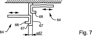
版保持体58の別の実施例は、有利にはシャフト44のための特に小さな構造高さを許容しており、この実施例では、第2の版37は、版胴33の軸方向で一平面上に延びる載設部54の上方で、少なくとも1つの保持エレメント64によって、上位の格納位置で保持され、この場合保持エレメント64は、たとえばガイドレール64、有利には互いに平行に延びる2つのガイドレール64として形成されており(図7〜図9)、この場合ガイドレール64はシャフト44内に存在する第2の版37を、両縦側面で、長さL部分の少なくとも一部に沿って上位の格納位置で保持する。ガイドレール64を備えた版保持体の実施例は、第2の版37の端部03;04における掛止脚部13;14が、版37の全幅Bにわたって延びておらず、版37の縦側面に到達していないことを前提としている。したがって版37の縦側面は、版37の載設面02の領域に、掛止脚部13;14に対する突出部を形成する。この突出部は、版37をガイドレール64に案内可能に構成するために必要である。保持エレメント64、特に各ガイドエレメント64は、たとえばU字形の、版37の1縦側面をある程度の遊びを有して包囲する湾曲部材から成っており、湾曲部材に、第2の版37は版胴33とは反対側から挿入可能である。第2の版37は、ガイドレール64によって、有利には側面における狭幅な領域で保持され、この場合保持は、特に鉛直方向の支持として作用し、ひいては版37に作用する重力FGに対する支持として作用する。ガイドレール64は、有利には形状安定性の材料、たとえば金属またはプラスチックから製作されている。   Another embodiment of the plate holder 58 advantageously allows a particularly small structural height for the shaft 44, in which the second plate 37 is one in the axial direction of the plate cylinder 33. Above the mounting part 54 extending in a plane, it is held in a higher storage position by at least one holding element 64, in which case the holding element 64 is for example a guide rail 64, preferably two guides extending parallel to each other. It is formed as a rail 64 (FIGS. 7 to 9). In this case, the guide rail 64 extends the second plate 37 existing in the shaft 44 along at least a part of the length L portion on both longitudinal sides. Hold at the upper storage location. In the embodiment of the plate holder provided with the guide rail 64, the latching leg portions 13; 14 at the ends 03; 04 of the second plate 37 do not extend over the entire width B of the plate 37, and It is assumed that the side has not been reached. Accordingly, the vertical side surface of the plate 37 forms a protruding portion with respect to the latching leg portions 13 and 14 in the region of the mounting surface 02 of the plate 37. This projecting portion is necessary to configure the plate 37 so that it can be guided to the guide rail 64. The holding element 64, in particular, each guide element 64 is formed of a curved member that surrounds one longitudinal side surface of the plate 37 with a certain amount of play, for example, a U-shape, and the second plate 37 is a plate. It can be inserted from the side opposite to the body 33. The second plate 37 is held by the guide rail 64, preferably in a narrow area on the side, in which case the holding acts as a support in the vertical direction and thus as a support for the gravity FG acting on the plate 37. Works. The guide rail 64 is preferably made from a shape-stable material, such as metal or plastic.

ガイドレール64によって保持される第2の版37を載設部54に積み置くために、少なくとも1つのガイドレール64は、第2の版37の幅Bの方向で可動である。有利には両ガイドレール64は第2の版37の幅Bに沿って互いに反対方向で可動であるので、両ガイドレール64は少なくとも短時間互いに離間運動して、版37の縦側面をもはや鉛直方向で支持しなくなるように相互間隔を拡大し、これによって第2の版37は、この第2の版37に作用する重力FGに従って、ガイドレール64の間を通って載設部54に落下する。保持エレメント64が第1の運転状態で第2の版37を、たとえば電力または磁力によって上位の格納位置に保持すると、保持エレメント64は有利には第1の運転状態から第2の運転状態に遠隔操作され、この場合第2の運転状態によって保持エレメント64が指示されて、版37と保持エレメント64とが互いに分離され、版37は、シャフト44に設けられた保持エレメント64から解放される際に、自由落下によって、ひいては専ら版37に作用する重力FGによって、有利には直接的に鉛直方向で上位の格納位置の下方に位置する格納位置に位置交換する。第2の版37は、シャフト44における下位の格納位置でも上位の格納位置でも15°を下回る傾度で、有利には水平に保持される。少なくとも第2の版37のための支承部として形成されたガイドレール64は、延伸長さ部分で、極めて小さな傾度または水平方向の経過を有している。   In order to stack the second plate 37 held by the guide rail 64 on the mounting portion 54, at least one guide rail 64 is movable in the direction of the width B of the second plate 37. Advantageously, both guide rails 64 are movable in opposite directions along the width B of the second plate 37, so that both guide rails 64 move away from each other for at least a short time so that the longitudinal sides of the plate 37 are no longer vertical. The mutual distance is enlarged so that the second plate 37 is not supported in the direction, so that the second plate 37 falls between the guide rails 64 and falls on the mounting portion 54 according to the gravity FG acting on the second plate 37. . When the holding element 64 holds the second plate 37 in the upper storage position, for example by electric power or magnetic force, in the first operating state, the holding element 64 is advantageously remote from the first operating state to the second operating state. In this case, the holding element 64 is instructed by the second operating state, the plate 37 and the holding element 64 are separated from each other, and the plate 37 is released from the holding element 64 provided on the shaft 44. The position is exchanged to the storage position which is preferably directly below the upper storage position in the vertical direction by free fall and by gravity FG acting exclusively on the plate 37. The second plate 37 is preferably held horizontally with an inclination of less than 15 ° in the lower and upper storage positions of the shaft 44. The guide rail 64 formed as a bearing for at least the second plate 37 is an extended length part and has a very small inclination or horizontal course.

側方で作用するガイドレール64からの第2の版37の解放は、有利には第2の版37の載設面2に対して垂直に位置するストッパ67によって助成され、このストッパ67は有利にはシャフト44内で定置に配置されており、この場合有利には第2の版37の両縦側面側にそのようなストッパ67が配置されているので、第2の版37の幅Bに沿って方向付けられた、版37を保持するガイドレール64の互いに逆向きの運動の間、版37は両側に配置されたストッパ67によって、版37の載置面02によって形成された平面上で定置に維持される。ストッパ67は、版37を、互いに離間運動するガイドレール64から掻き落とし、ここでは版37はストッパ67に当接し、この場合同時にガイドレール64の運動によって版37から鉛直方向の支持がなくなる。第2の版37の分離は、有利には印刷機に所属するガイドスタンドによって操作可能な駆動装置69によって行われ、この場合駆動装置69はガイドレール64に作用して、ガイドレール64を調節距離s68に沿って運動させる。   The release of the second plate 37 from the guide rail 64 acting on the side is advantageously assisted by a stopper 67 which is positioned perpendicular to the mounting surface 2 of the second plate 37, which is advantageous. Is disposed stationary in the shaft 44. In this case, advantageously, such a stopper 67 is disposed on both longitudinal side surfaces of the second plate 37, so that the width B of the second plate 37 is reduced. During the opposite movements of the guide rails 64 holding the plate 37, which are directed along, the plate 37 is placed on the plane formed by the mounting surface 02 of the plate 37 by means of stoppers 67 arranged on both sides. Maintained in place. The stopper 67 scrapes the plate 37 away from the guide rails 64 that move away from each other. Here, the plate 37 abuts against the stopper 67, and in this case, the movement of the guide rails 64 causes the plate 37 to no longer be supported in the vertical direction. The separation of the second plate 37 is preferably effected by a drive device 69 which can be operated by a guide stand belonging to the printing press, in which case the drive device 69 acts on the guide rail 64 and causes the guide rail 64 to be adjusted distance. Exercise along s68.

版胴33上で、版胴33の軸方向で相並んで複数の版が配置されていて、かつシャフト44に版胴33の軸方向で複数の版37が相並んで配置されている場合、有利には、隣接する第2の版37に作用するガイドレール64は、版マガジン39内で載設部54の上方でそれぞれ異なる2平面上に、つまり鉛直方向で互いにずらして配置されており、この場合版胴33の軸方向で相前後して位置する平面は、有利には交互にずらして配置されている。版37の第1の格納位置を形成する平面をずらして配置したことによって、版胴33の軸方向で相並んで位置する、つまり隣接して配置された版37の間の間隔a67はできるだけ小さく維持することができる。間隔a67は、有利には版胴33上で軸方向で相並んで配置された、つまり隣接して配置された版37が有する間隔に相当する。版胴33の軸方向で相並んで配置された平面、つまり第1の格納位置から、載設部54に積み置かれ、ひいては第2の格納位置にもたらされる版37は、搬送装置57によって、個別的に、または有利には同時にまとめて版胴33に供給され、この場合同時的な搬送は、版胴33における版37の迅速な交換にとって有利である。版胴33の軸方向で相並んで配置されたそれぞれ異なる平面に格納された版37は、同時に、または少なくとも迅速に順次第2の格納位置に位置交換する。同時にまとめて版胴33に供給された版37は、版胴33上で軸方向で相並んで配置されている。   In the case where a plurality of plates are arranged side by side in the axial direction of the plate cylinder 33 on the plate cylinder 33 and a plurality of plates 37 are arranged side by side in the axial direction of the plate cylinder 33 on the shaft 44, Advantageously, the guide rails 64 acting on the adjacent second plates 37 are arranged on two different planes in the plate magazine 39 above the mounting portion 54, that is, shifted from each other in the vertical direction, In this case, the planes positioned one after the other in the axial direction of the plate cylinder 33 are preferably arranged alternately. By disposing the planes forming the first storage positions of the plates 37, the distance a67 between the plates 37 that are positioned side by side in the axial direction of the plate cylinder 33, that is, adjacently disposed, is as small as possible. Can be maintained. The interval a67 advantageously corresponds to the interval between the plates 37 arranged side by side in the axial direction on the plate cylinder 33, that is, adjacent to each other. Plates 37 stacked in the axial direction of the plate cylinder 33, that is, from the first storage position, are stacked on the mounting portion 54 and eventually brought to the second storage position. The plate cylinders 33 are fed individually or advantageously simultaneously to the plate cylinder 33, in which case simultaneous conveyance is advantageous for the rapid exchange of the plate 37 in the plate cylinder 33. The plates 37 stored in different planes arranged side by side in the axial direction of the plate cylinder 33 are exchanged to the second storage position simultaneously or at least rapidly. The plates 37 that are simultaneously supplied to the plate cylinder 33 are arranged side by side on the plate cylinder 33 in the axial direction.

図8に示した実施例では、4つの第2の版37が、それぞれ第1の格納位置で、版胴33の軸方向で相並んで配置されており、この場合各版37はそれぞれ縦側面でガイドレール64に保持されている。各版37の鉛直方向のずれは、数ミリメートル、たとえば4mm〜6mmであり、ガイドレール64の構造高さ、有利には1倍〜2倍の構造高さにほぼ相当する。ガイドレール64の運動は、第2の版37の幅Bに沿って、たとえばガイドレール64の直線的なスライドによって行われ、ガイドレールの運動は、ガイドレール64の旋回運動によっても行うことができ、この場合ガイドレール64は旋回軸線を中心に旋回可能であり、この旋回軸線は、版37の、ガイドレール64によって支持される側面に対して平行に延びている。ガイドレール64は、たとえば少なくとも1つの旋回アーム68に取り付けることができ、旋回アーム68はたとえば第2の版37の載設面02によって形成される平面上で旋回可能であり、これについては図9に方向矢印で示した。旋回アーム68の一方の端部はガイドレール64と結合されていて、他方の端部はシャフト44内で有利には定置に取り付けられており、旋回アーム68は、たとえば側方でガイドレール64に作用するばねエレメント68、たとえば板ばね68として形成することができ、この場合旋回アーム68と結合されたガイドレール64は、駆動装置69、たとえば操作可能な、特に遠隔操作可能な磁石69によって、第2の版37を保持するか、または版37から解放する運転位置に運動される。第2の版37の幅Bに沿って運動可能なガイドレール64を形成する調節距離s68は、数ミリメートル範囲、たとえば2mm〜10mm、有利には4mmである。有利にはこの実施例では、ストッパ67が設けられており、ガイドレール64が運動によって版37の支持を解消する間、このストッパ67に版37がガイドレール64によって支持された面で当接する。版胴33の軸方向で隣接する2つの版37は、同じストッパ67のそれぞれ反対側に当接する。上位の格納位置から下位の格納位置へ位置交換を行う間、版37は側面でストッパ67に沿って鉛直方向で下方に移動することができるので、上位の格納位置から解放された版37は、案内された運動経路で下位の格納位置に到達する。ストッパ67は、格納位置を交換する版37のために、有利には載設部54まで達する側方案内機能を有している。   In the embodiment shown in FIG. 8, four second plates 37 are arranged side by side in the axial direction of the plate cylinder 33 at the first retracted position, and in this case, each plate 37 is a vertical side surface. Is held by the guide rail 64. The vertical displacement of each plate 37 is a few millimeters, for example 4 mm to 6 mm, and substantially corresponds to the structural height of the guide rail 64, preferably 1 to 2 times the structural height. The movement of the guide rail 64 is performed by, for example, a linear slide of the guide rail 64 along the width B of the second plate 37, and the movement of the guide rail can also be performed by a turning movement of the guide rail 64. In this case, the guide rail 64 can pivot about the pivot axis, and the pivot axis extends parallel to the side surface of the plate 37 supported by the guide rail 64. The guide rail 64 can be attached, for example, to at least one swivel arm 68, which can be swiveled on a plane formed by the mounting surface 02 of the second plate 37, for example, as shown in FIG. Indicated by a directional arrow. One end of the swivel arm 68 is connected to the guide rail 64 and the other end is advantageously fixedly mounted in the shaft 44, and the swivel arm 68 is, for example, laterally connected to the guide rail 64. The actuating spring element 68, for example a leaf spring 68, in this case the guide rail 64 coupled to the swivel arm 68 is connected by a drive device 69, for example an operable, in particular remotely operable magnet 69. The second plate 37 is moved to an operating position to hold or release from the plate 37. The adjustment distance s68 forming the guide rail 64 movable along the width B of the second plate 37 is in the range of a few millimeters, for example 2 mm to 10 mm, preferably 4 mm. Advantageously, in this embodiment, a stopper 67 is provided, and the plate 37 abuts against the stopper 67 at the surface supported by the guide rail 64 while the guide rail 64 releases the support of the plate 37 by movement. Two plates 37 adjacent to each other in the axial direction of the plate cylinder 33 abut against the opposite sides of the same stopper 67. During the position exchange from the upper storage position to the lower storage position, the plate 37 can move downward in the vertical direction along the stopper 67 on the side surface, so that the plate 37 released from the upper storage position is A lower storage position is reached by the guided movement path. The stopper 67 has a side guide function which advantageously reaches the mounting part 54 for the plate 37 whose storage position is exchanged.

一般的に述べると、印刷機の同じ胴06;31;33から相前後して排出される少なくとも2つの被覆体01;36;37を格納する方法では以下のステップが行われる。a)予め胴06;31;33から排出された被覆体01;36;37が、第1の格納位置から第2の格納位置に搬送され、b)予め排出された被覆体01;36;37に続いて排出される被覆体01;36;37が、予め排出された被覆体01;36;37の第1の格納位置に格納され、c)第2の格納位置における予め排出された被覆体01;36;37と、予め排出された被覆体01;36;37の第1の格納位置に後続排出された被覆体01;36;37とが、長さLに沿って、長さLに直交する間隔を有して格納され、d)被覆体01;36;37が各載設面02で、少なくとも大部分にわたって重畳して、有利には少なくとも80%にわたって重畳するか、完全に、もしくは実質的に完全に重畳して格納される。予め排出された被覆体01;36;37と、後続排出された被覆体01;36;37とは、長さLに沿って鉛直方向で、また水平方向で相互間隔を有して格納することができる。有利には予め排出された被覆体01;36;37は、直線運動によって、特に載設面02に対して直交する、両格納位置を非間接的つまり直接的に結ぶ直線運動によって、また後行端部04の運動によって、第2の格納位置に搬送される。これについてはあとで詳しく説明する。   Generally speaking, in the method of storing at least two coverings 01; 36; 37 discharged one after the other from the same cylinder 06; 31; 33 of the printing press, the following steps are performed. a) The covering body 01; 36; 37 previously discharged from the cylinder 06; 31; 33 is conveyed from the first storage position to the second storage position, and b) the covering body 01; 36; 37 discharged in advance. Is then stored in the first storage position of the pre-discharged covering 01; 36; 37, and c) the pre-discharged covering in the second storage position. 01; 36; 37 and the previously discharged covering 01; 36; 37 discharged to the first retracted position of the covering body 01; 36; 37 along the length L to the length L. D) the coverings 01; 36; 37 are superimposed on each mounting surface 02 at least for the most part, preferably at least 80%, or completely, or Stored substantially completely superimposed. The pre-discharged covering 01; 36; 37 and the subsequent discharged covering 01; 36; 37 are stored along the length L in the vertical direction and in the horizontal direction with mutual spacing. Can do. The pre-discharged coverings 01; 36; 37 are preferably applied by linear movement, in particular by linear movement perpendicular to the mounting surface 02, indirectly connecting both storage positions, i.e. directly. It is conveyed to the second storage position by the movement of the end portion 04. This will be described in detail later.

特にシャフト44において、たとえば載設部54に載設する第1の版37のためのスライダ56に、また第2の版37のための、L字形に形成された角度部材61に、コードリーダ71を取り付けると有利であり、コードリーダ71は、有利には各版37の後行端部04における掛止脚部14に取り付けられた各コード化情報を読み取り、つまり版を識別するためのサインを検出し、これによって版胴33のために設けられ、かつ制御ユニットに格納された配置プランとの、有利には電子式に制御ユニットにおいて実行される調整で、シャフト44に搬入された版37が、意図された印刷過程の配置プランに相当するかどうか、また意図された配置のために、シャフト44に搬入された版37が正しい順序で存在するかどうかを検査することができる。そうして版胴33に版37を取り付けるまえに、適当な通知、たとえばエラー通知、つまり作業員に取付エラーを警告する通知が形成され、たとえば印刷装置に対応配置されたガイドスタンドに送られ、そこで、または印刷装置で表示される。   In particular, in the shaft 44, for example, a code reader 71 is provided on a slider 56 for the first plate 37 mounted on the mounting portion 54 and an angle member 61 formed in an L shape for the second plate 37. The code reader 71 advantageously reads each piece of coded information attached to the latching leg 14 at the trailing edge 04 of each plate 37, i.e. a sign for identifying the plate. The plate 37 carried on the shaft 44 is detected and adjusted with the arrangement plan provided for the plate cylinder 33 and stored in the control unit, preferably electronically in the control unit. Check whether it corresponds to the layout plan of the intended printing process and whether the plates 37 loaded into the shaft 44 are present in the correct order for the intended layout. It can be. Thus, before attaching the plate 37 to the plate cylinder 33, an appropriate notification, for example, an error notification, that is, a notification for warning an installation error to the operator is formed, and sent to a guide stand arranged corresponding to the printing device, for example. Therefore, it is displayed on the printing apparatus.

コード化情報は、有利には人間が読みとれるコードに対して追加的に、たとえばバーコードとして形成することができる。したがってコードリーダ71は、シャフト44内で、有利には版胴33とは反対側の端部に配置されており、この場合コードリーダ71の読取方向は、版37の長さLに対して平行に、または有利には版37の幅Bに対して平行に向けられている。有利な実施例では、コードリーダ71は、有利にはリニアガイドで移動可能にシャフト内もしくはシャフト表面に配置されているか、または有利には版37の幅Bに対して45°傾斜付けされた移動可能なミラーが設けられており、ミラーは、版37に取り付けられたコード化情報の検出信号もしくは読取信号を、シャフト44の片側に配置されたコードリーダ71に変向するので、シャフト44内に格納された版37に取り付けられたコード化情報を読み取るために、単個のコードリーダ71しか必要とされない。格納された複数の版37のために単個のコードリーダ71しか使用しないことによって、コストを大幅に削減することができる。単個のコードリーダ71しか使用しない場合、コードリーダ71またはミラーは、版37の幅Bに対して平行に、つまり版胴33の軸方向で、有利には複数のシャフト44に沿って、かつ/またはシャフト44の1つに積み重ねられた版37に沿って、鉛直方向で高さ移動可能であるので、コードリーダ71またはミラーは、それぞれ異なる格納位置に格納された版37のコード化情報を検出する。コードリーダ71または少なくとも1つの別のセンサ91は、意図される版交換が正常に行われたかどうかを監視し、かつ/または検査するために使用することができる。二重配置のようなエラー、または配置エラー、つまり適切でない位置への版37の取付は回避され、比較的大きな損害が生じるまえに、少なくとも有利には印刷機のガイドスタンドに送られた通知によってこれを確認することができる。   The encoded information can advantageously be formed in addition to the human readable code, for example as a bar code. Accordingly, the code reader 71 is disposed in the shaft 44, preferably at the end opposite to the plate cylinder 33. In this case, the reading direction of the code reader 71 is parallel to the length L of the plate 37. Or advantageously oriented parallel to the width B of the plate 37. In an advantageous embodiment, the code reader 71 is arranged in the shaft or on the surface of the shaft, preferably movably with a linear guide, or preferably with a movement inclined by 45 ° with respect to the width B of the plate 37. A possible mirror is provided, which redirects the detection signal or read signal of the coded information attached to the plate 37 to a code reader 71 located on one side of the shaft 44, so Only a single code reader 71 is required to read the encoded information attached to the stored plate 37. By using only a single code reader 71 for a plurality of stored plates 37, the cost can be greatly reduced. If only a single code reader 71 is used, the code reader 71 or mirror is parallel to the width B of the plate 37, ie in the axial direction of the plate cylinder 33, preferably along a plurality of shafts 44, and Since the height can be moved in the vertical direction along the plate 37 stacked on one of the shafts 44, the code reader 71 or the mirror can store the coded information of the plate 37 stored in different storage positions. To detect. The code reader 71 or at least one other sensor 91 can be used to monitor and / or inspect whether the intended plate change was successful. Errors such as double placement, or placement errors, i.e. the mounting of the plate 37 in the wrong position, are avoided, and at least advantageously by a notification sent to the guide stand of the printing press before relatively large damage occurs This can be confirmed.

図6には、別のシャフト42を図示しており、この別のシャフト42は、版胴33から離間された版37を収容するのに役立つ。シャフト42は、たとえば傾斜付けされた載設部72を備えており、載設部72は、版胴33に取り付けようとする版37を準備するためのシャフト44に設けられた載設部54と同様に有利には扁平ではなく、平行な条片72またはスライドレール72として形成されており、ここでは載設部72の傾斜によって、シャフト42は、有利には版胴33とは反対側で拡張され、これによってシャフト42は、版胴33とは反対側で作業員にとって良好にアプローチ可能であり、したがってシャフト42に積み置かれた版37の取り出しが簡素化される。シャフト42に設けられた載設部72は、たとえば水平線Hに対して傾斜角δだけ傾斜付けされており、この場合傾斜角δは5°〜15°、有利には7°である。図6に示した実施例では、版胴33から取り出された版37を収容するためのシャフト42は、版胴33に取り付けようとする版37を準備するためのシャフト44の下方に位置しており、この配置構成は有利であるが、絶対的なものではない。シャフト42;44は、逆の順序で配置するか、または互いに別個に配置することもできる。   FIG. 6 illustrates another shaft 42 that serves to accommodate a plate 37 spaced from the plate cylinder 33. The shaft 42 includes, for example, an inclined mounting portion 72, and the mounting portion 72 includes a mounting portion 54 provided on the shaft 44 for preparing the plate 37 to be attached to the plate cylinder 33. Likewise, it is preferably not flat but formed as parallel strips 72 or slide rails 72, where the shaft 42 is preferably expanded on the side opposite to the plate cylinder 33 due to the inclination of the mounting 72. Thus, the shaft 42 can be satisfactorily approached by the operator on the opposite side of the plate cylinder 33, thus simplifying the removal of the plate 37 stacked on the shaft 42. The mounting portion 72 provided on the shaft 42 is inclined by, for example, an inclination angle δ with respect to the horizontal line H. In this case, the inclination angle δ is 5 ° to 15 °, preferably 7 °. In the embodiment shown in FIG. 6, the shaft 42 for accommodating the plate 37 taken out from the plate cylinder 33 is located below the shaft 44 for preparing the plate 37 to be attached to the plate cylinder 33. This arrangement is advantageous but not absolute. The shafts 42; 44 can be arranged in the reverse order or separately from each other.

シャフト42の有利な実施例では、シャフト42内で、版胴33の軸方向で相並んで少なくとも2つの版37が格納可能である。このような実施例によって、特に版胴33上に、軸方向で少なくとも2つの版37が配置可能である場合、版37の特に迅速な取り出しが実現される。なぜならば複数の版37を同時に版胴33から取り出すことができるからである。版胴33上に、軸方向でたとえば少なくとも4つの版37が配置可能である場合、安定性の理由から、たとえば2つのシャフト42を版胴33の軸方向で相並んで配置すると有利である。各シャフト42における、版37の幅Bによって規定された格納スペースは、版胴33の周に沿って配置可能である数と少なくとも同数の版37が格納可能であるように形成されており、この場合版37の格納は、各格納スペースで上下にスタックを成すように行われる。各シャフト42に、10まで、少なくとも8つまでの版37が格納可能であるので、版胴33から導出される版37は、シャフト42内で集めることができ、シャフト42は版37の交換ごとに作業員によって必ずしも交換する必要はない。相並んで配置されたシャフト42の数とは無関係に、格納スペースは、版胴33の軸方向で、版37が版胴33上で配置されているのと同じ狭幅の相互間隔を有している。   In an advantageous embodiment of the shaft 42, at least two plates 37 can be stored in the shaft 42 side by side in the axial direction of the plate cylinder 33. With such an embodiment, a particularly quick removal of the plate 37 is realized, in particular when at least two plates 37 can be arranged in the axial direction on the plate cylinder 33. This is because a plurality of plates 37 can be taken out from the plate cylinder 33 simultaneously. If, for example, at least four plates 37 can be arranged on the plate cylinder 33 in the axial direction, it is advantageous for reasons of stability to arrange, for example, two shafts 42 side by side in the axial direction of the plate cylinder 33. The storage space defined by the width B of the plate 37 in each shaft 42 is formed such that at least the same number of plates 37 can be stored along the circumference of the plate cylinder 33. The case 37 is stored so as to form a stack vertically in each storage space. Since each shaft 42 can store up to 10 and up to 8 plates 37, the plates 37 derived from the plate cylinder 33 can be collected in the shaft 42, and the shaft 42 is replaced every time the plate 37 is replaced. However, it is not always necessary to replace it by a worker. Regardless of the number of shafts 42 arranged side by side, the storage space has the same narrow mutual spacing in the axial direction of the plate cylinder 33 as the plate 37 is arranged on the plate cylinder 33. ing.

版胴33に向いた側で、版胴33から離間された版37を収容するためのシャフト42は、少なくとも版胴33に当接された運転状態で、版胴33の外周面07の傍に配置されたガイドエレメント73を備えており、ガイドエレメント73は、たとえば薄板ガイド73、楔形部材73、または転動エレメント73たとえばローラ73として形成されていて、かつ版胴33から離間しようとする版37の後行端部04をシャフト42に案内する役割を有している。版胴33の外周面07からのガイドエレメント73の間隔a73は、有利には版37の後行端部04における折り曲げられた掛止脚部14の長さl14よりもそれほど大きくなっておらず、特にガイドエレメント73の間隔a73は、掛止脚部14の1倍〜2倍の値を有している(図6)。版胴33から離間しようとする版37は印刷画像面で、ガイドエレメント73に接触するので、版37の表面に関する、回動可能に支承された転動エレメント73とのコンタクトは、扁平に形成された不動の楔形部材73に沿った滑動よりもソフトである。このような見解は、版37を再度使用するよう所望されていて、したがって引っ掻きまたは擦過跡による印刷画像面の破損を回避する必要がある場合に特に有意義である。ガイドエレメント73にセンサ91を取り付けることができ、センサ91は、版胴33から離間しようとする版37と接触する形式で、または有利には非接触式、たとえば誘導式に、版胴33から離間しようとする版37の後行端部04における掛止脚部14が版胴33の溝08内に配置された保持手段21の作動後に実際に緊締解除されたかどうかを検査する。検査によってセンサ91は信号を、たとえば印刷機に所属するガイドスタンドに送る。センサ91から送られた信号に基づいて、版胴33から離間しようとする版37の排出過程を継続することができるか、または障害を克服するための手段を導入する必要があるかが決定される。ガイドエレメント73に、版胴33の軸方向で有利には複数の、たとえば4つまたは6つのセンサ91が設けられており、すなわち版胴33上に軸方向で相並んで配置可能な版37のためにそれぞれ少なくとも1つのセンサ91が設けられている。   On the side facing the plate cylinder 33, the shaft 42 for accommodating the plate 37 separated from the plate cylinder 33 is at least in an operating state in contact with the plate cylinder 33, near the outer peripheral surface 07 of the plate cylinder 33. The guide element 73 is arranged, and the guide element 73 is formed, for example, as a thin plate guide 73, a wedge-shaped member 73, or a rolling element 73, such as a roller 73, and is a plate 37 to be separated from the plate cylinder 33. It has a role of guiding the trailing end portion 04 to the shaft 42. The distance a73 of the guide element 73 from the outer peripheral surface 07 of the plate cylinder 33 is preferably not so much larger than the length l14 of the bent latching leg 14 at the trailing end portion 04 of the plate 37, In particular, the distance a73 of the guide element 73 has a value that is 1 to 2 times that of the latch leg 14 (FIG. 6). Since the plate 37 to be separated from the plate cylinder 33 comes into contact with the guide element 73 on the printed image surface, the contact with the rolling element 73 that is rotatably supported on the surface of the plate 37 is formed flat. It is softer than sliding along the stationary wedge-shaped member 73. Such a view is particularly meaningful when it is desired to use the plate 37 again and therefore it is necessary to avoid damage to the printed image surface due to scratches or scratches. A sensor 91 can be mounted on the guide element 73, the sensor 91 being spaced from the plate cylinder 33 in contact with the plate 37 to be separated from the plate cylinder 33, or advantageously in a non-contact manner, for example inductive manner. It is checked whether or not the fastening leg portion 14 at the trailing end portion 04 of the plate 37 to be actually released is tightened after the operation of the holding means 21 disposed in the groove 08 of the plate cylinder 33. By inspection, the sensor 91 sends a signal to, for example, a guide stand belonging to the printing press. Based on the signal sent from the sensor 91, it is determined whether it is possible to continue the discharge process of the plate 37 which is going to be separated from the plate cylinder 33 or to introduce means for overcoming the obstacles. The The guide element 73 is preferably provided with a plurality of, for example, four or six sensors 91 in the axial direction of the plate cylinder 33, that is to say of the plate 37 which can be arranged side by side in the axial direction on the plate cylinder 33. For this purpose, at least one sensor 91 is provided.

有利な実施例では、版胴33から離間しようとする版37の後行端部04における掛止脚部14は、ガイドエレメント73を通過したあとで、シャフト42に設けられた載設部72に到達する前に、有利にはガイドエレメント73から間隔を有して配置された第1のランプ74に載設され、この場合第1のランプ74は、載設部72に向かって先ず上方傾斜しており、頂点76を過ぎると載設部72に向かって再び下方傾斜している。第1のランプ74は、有利には載設部72と堅固に結合されている。胴33から離間しようとする版37をシャフト42に導入する過程で、後行端部04における掛止脚部14は、第2のランプ77に到達する。第2のランプ77のフランクは頂点78を過ぎると、つまり版胴33とは反対側で、有利には極めて急に、載設部72に向かって下方傾斜している。版37がシャフト42に導入される方向で、頂点78の後方で僅かな間隔a77を有して(図14)、第2のランプ77と堅固に結合されたストッパ79が配置されており、ストッパ79に、版37の後行端部における掛止脚部14が当接する。間隔a77は、数ミリメートルの値、有利には長さl14よりも小さな値、特に版37の後行端部における折り曲げられた掛止脚部14の半分の長さl14よりも小さな値を有している。版37の後行端部04における掛止脚部14がストッパ79に当接すると、掛止脚部14は、間隔a77によって形成された中間スペースに入り込んで、有利には第2のランプ77に後方から係合する。第2のランプ77およびこれに結合されたストッパ79は、搬送装置81によって直線的に、かつ載設部72に対して平行に移動可能で、これによって版胴33から離間しようとする版37は完全にシャフト42に入り込むように搬送することができる。搬送装置81は、特に版37の後行端部04における折り曲げられた掛止脚部14のための第2のランプ77に設けられた急なフランクと協働して、版37をシャフト42に搬送する連行装置を形成しており、搬送装置81は、たとえばベルト駆動装置81またはリニア駆動装置として、有利にはニューマチック式の駆動装置81として、特にピストンロッドの設けられていない両側作用式のリニア駆動装置81として形成されている。第1のランプ74も第2のランプ77も、たとえば扁平な平面から形成されるのではなく、コームの歯部のように平行に配置された複数のガイドレールから成っている。第2のランプ77は、たとえばこれに応じて屈曲された単数または複数の金属ストリップから成形することができる。   In an advantageous embodiment, the latching leg 14 at the trailing end 04 of the plate 37 which is to be separated from the plate cylinder 33 passes through the guide element 73 and then rests on the mounting portion 72 provided on the shaft 42. Before arriving, it is mounted on a first ramp 74 which is preferably arranged at a distance from the guide element 73, in which case the first ramp 74 first tilts upward towards the mounting portion 72. In addition, after passing the apex 76, it is inclined downward again toward the mounting portion 72. The first lamp 74 is preferably firmly connected to the mounting part 72. In the process of introducing the plate 37 to be separated from the body 33 into the shaft 42, the latching leg portion 14 at the trailing end portion 04 reaches the second ramp 77. The flank of the second ramp 77 is inclined downwardly toward the mounting portion 72 after the apex 78, that is, on the side opposite to the plate cylinder 33, preferably very steeply. A stopper 79 is disposed in the direction in which the plate 37 is introduced into the shaft 42 with a slight distance a77 behind the apex 78 (FIG. 14) and is firmly connected to the second ramp 77. 79, the latching leg 14 at the trailing end of the plate 37 abuts. The distance a77 has a value of a few millimeters, preferably less than the length l14, in particular less than the half length l14 of the folded leg 14 at the trailing edge of the plate 37. ing. When the latching leg 14 at the trailing edge 04 of the plate 37 abuts against the stopper 79, the latching leg 14 enters the intermediate space formed by the interval a77 and is advantageously brought into contact with the second ramp 77. Engage from behind. The second ramp 77 and the stopper 79 coupled thereto can be moved linearly and in parallel to the mounting portion 72 by the conveying device 81, whereby the plate 37 to be separated from the plate cylinder 33 is It can be conveyed so as to completely enter the shaft 42. The conveying device 81 cooperates with the steep flank provided in the second ramp 77 for the bent latching leg 14 at the trailing end 04 of the plate 37, in particular, to bring the plate 37 to the shaft 42. An entraining device for conveying is formed, and the conveying device 81 is, for example, a belt driving device 81 or a linear driving device, preferably a pneumatic driving device 81, in particular a double acting type without a piston rod. The linear drive device 81 is formed. The first lamp 74 and the second lamp 77 are not formed from a flat plane, for example, but are composed of a plurality of guide rails arranged in parallel like the teeth of the comb. The second lamp 77 can be formed, for example, from one or more metal strips bent accordingly.

版胴33とは反対側で、シャフト42に昇降装置82、特に版昇降装置82が配置されており、ここでは版昇降装置82は、たとえば有利には載設部72に対して垂直に移動可能なプランジャ83を備えており、プランジャ83の端部に、たとえばL字形、特にU字形に形成された昇降アーム84が配置されており、この場合版37の後行端部04における折り曲げられた掛止脚部14は昇降アーム84に載設されるか、またはこれを包囲するように調節される。版昇降装置82は、有利には定置の2つの運転位置を有していて、つまりプランジャ83の挿入移動された運転位置とプランジャ83の挿出移動された運転位置とを有しており、プランジャの挿入移動された運転位置では、昇降アーム84は載設部72によって規定された平面の下方に位置しており、プランジャの挿出移動された運転位置では、昇降アーム84は版胴33から離間された版37を載設部72から持ち上げる。ここでは版昇降装置82はストロークa82を実行し、このストロークa82は、版37の後行端部04における折り曲げられた掛止脚部14の長さl14よりも大きくなっている。有利にはストロークa82は、掛止脚部14の1倍〜2倍の値を有している。したがって版昇降装置82は、版胴33から離間された版37を、一時的な第1の格納位置から最終的な第2の格納位置に持ち上げる。   On the opposite side of the plate cylinder 33, an elevating device 82, in particular a plate elevating device 82, is arranged on the shaft 42, where the plate elevating device 82 is advantageously movable, for example, perpendicularly to the mounting part 72. A plunger 83 is provided, and an elevating arm 84 formed in an L shape, in particular, a U shape, for example, is arranged at the end of the plunger 83. The leg 14 is mounted on the lifting arm 84 or adjusted so as to surround it. The plate lifting / lowering device 82 preferably has two stationary operating positions, that is, an operating position where the plunger 83 is inserted and moved, and an operating position where the plunger 83 is inserted and moved. The lift arm 84 is located below the plane defined by the mounting portion 72 in the operation position moved and inserted, and the lift arm 84 is separated from the plate cylinder 33 in the operation position where the plunger is inserted and moved. The formed plate 37 is lifted from the mounting portion 72. Here, the plate lifting / lowering device 82 executes a stroke a 82, and this stroke a 82 is larger than the length l 14 of the bent latching leg portion 14 at the trailing end portion 04 of the plate 37. The stroke a82 preferably has a value that is 1 to 2 times that of the latch leg 14. Accordingly, the plate lifting device 82 lifts the plate 37 separated from the plate cylinder 33 from the temporary first storage position to the final second storage position.

版昇降装置82の上方、特に昇降アーム84の上方に、有利には版37の幅Bに対して実質的に平行に延びる旋回軸線を中心に旋回可能な、たとえば条片状のフラップ86の構成をした安全エレメント86が配置されており、フラップ86の下縁は、昇降アーム84から間隔a86を有して位置しており、ここでは間隔a86は、有利には版37の後行端部04における折り曲げられた掛止脚部14の長さl14よりも小さく寸法付けされている。図6には、安全エレメント86の旋回性能を方向矢印で示した。安全エレメント86は、版昇降装置82によって持ち上げられた版37を確保して、シャフト42内での意図しないスリップまたはシャフト42からの離間を防止する。したがって作業員は、安全エレメント86を、持ち上げられた版37がシャフト42から取り出し可能になる前に、最初は旋回させておく必要がある。   A configuration of, for example, a strip-shaped flap 86 which can be swiveled above the plate lifting device 82, in particular above the lifting arm 84, preferably about a swiveling axis extending substantially parallel to the width B of the plate 37. The lower edge of the flap 86 is located at a distance a86 from the lifting arm 84, where the distance a86 is preferably the trailing edge 04 of the plate 37. Is dimensioned to be smaller than the length l14 of the folded leg 14 in FIG. In FIG. 6, the turning performance of the safety element 86 is indicated by a directional arrow. The safety element 86 secures the plate 37 lifted by the plate lifting device 82 to prevent unintentional slip or separation from the shaft 42 within the shaft 42. Thus, the operator must first pivot the safety element 86 before the lifted plate 37 can be removed from the shaft 42.

シャフト42内に配置された構成群の別の実施例は、図10〜図12に示した。この実施例では、有利には載設部72の中央領域に定置に配置されたストッパ79が設けられており、ここでは載設部72に沿って直線的に移動可能な搬送装置81と結合された版昇降装置82が、版胴33から離間しようとする版37の後行端部04における折り曲げられた掛止脚部14を、ストッパ79を越えて持ち上げ、版37は折り曲げられた脚部14で、有利には版昇降装置82によって持ち上げられた状態で、シャフト42の、版胴33とは反対側の端部まで搬送される。搬送装置81と版昇降装置82とは強制連結することができ、搬送装置81が版胴33とは反対向きの運動を行うと、直ちに版昇降装置82は版37の折り曲げられた掛止脚部14を持ち上げるようになっている。さらにストッパ79と、シャフト42の、版胴33に向いた側の端部との間に、別の版昇降装置87が設けられており、別の版昇降装置87は、版胴33から離間され、かつシャフト42に導入された版37の先行端部03を持ち上げ、版胴33から離間しようとする版37は、載設部72と、持ち上げられた版37との間でシャフト42に導入可能である。   Another embodiment of the group of components arranged in the shaft 42 is shown in FIGS. In this embodiment, a stopper 79 arranged in a stationary manner is advantageously provided in the central area of the mounting part 72, and here it is coupled to a conveying device 81 that can move linearly along the mounting part 72. The plate lifting / lowering device 82 lifts the bent latching leg portion 14 at the trailing end portion 04 of the plate 37 to be separated from the plate cylinder 33 over the stopper 79, and the plate 37 is bent. Thus, the shaft 42 is conveyed to the end of the shaft 42 opposite to the plate cylinder 33 while being lifted by the plate lifting device 82. The conveying device 81 and the plate lifting / lowering device 82 can be forcibly connected. When the conveying device 81 moves in a direction opposite to the plate cylinder 33, the plate lifting / lowering device 82 immediately stops the plate 37 when the plate 37 is bent. 14 is to be lifted. Further, another plate lifting device 87 is provided between the stopper 79 and the end of the shaft 42 on the side facing the plate cylinder 33, and the other plate lifting device 87 is separated from the plate cylinder 33. In addition, the plate 37 that is to be lifted up and separated from the plate cylinder 33 by lifting the leading end portion 03 of the plate 37 introduced into the shaft 42 can be introduced into the shaft 42 between the mounting portion 72 and the lifted plate 37. It is.

図13〜図35につき、特に版胴33において版37を交換する方法を説明する。これについては、版胴33に取り付けようとする新たな版37を提供するための上位のシャフト44に2つの版37が配置されており、版胴33の周に沿って2つの版37が載設されており、また版胴33から離間された版37を収容するための下位のシャフト42が空である、つまり版37が存在していないことから出発している。   A method for exchanging the plate 37 in the plate cylinder 33 will be described with reference to FIGS. In this regard, two plates 37 are arranged on the upper shaft 44 for providing a new plate 37 to be attached to the plate cylinder 33, and the two plates 37 are placed along the circumference of the plate cylinder 33. It starts from the fact that the lower shaft 42 for accommodating the plate 37, which is provided and spaced from the plate cylinder 33, is empty, i.e. the plate 37 is not present.

版胴33は、溝08における開口09で、下位のシャフト42に所属するガイドエレメント73の下方に存在する第1の位置に回動する。溝08内では、版胴33から離間しようとする版37の後行端部04における掛止脚部14が保持手段21によって保持されている。有利にはニューマチック式に操作可能で制御可能な押圧エレメント24が版胴33に当接される(図13)。   The plate cylinder 33 is rotated at the opening 09 in the groove 08 to a first position existing below the guide element 73 belonging to the lower shaft 42. In the groove 08, the retaining leg portion 14 is held by the holding means 21 at the trailing end portion 04 of the plate 37 that is about to be separated from the plate cylinder 33. Pneumatically operable and controllable pressing element 24 is preferably abutted against plate cylinder 33 (FIG. 13).

有利にはニューマチック式に操作可能な調節手段23は、保持手段21を、ばねエレメント22の力に抗して旋回させ、これによって版37の後行端部における掛止脚部14は、弾性的な内部応力に基づいて開口09から外側に弾性的に運動して、ガイドエレメント73に当接する。当接された押圧エレメント24は、版胴33の外周面07から版胴33の解放が進行するのを防止する(図14)。   The adjusting means 23, which is preferably actuated pneumatically, causes the holding means 21 to pivot against the force of the spring element 22, so that the latching leg 14 at the trailing end of the plate 37 is elastic. It elastically moves outward from the opening 09 based on the internal stress and contacts the guide element 73. The abutting pressing element 24 prevents the release of the plate cylinder 33 from proceeding from the outer peripheral surface 07 of the plate cylinder 33 (FIG. 14).

版胴33は、生産方向Pとは逆向きに回動して、この際に版胴37の後行端部04はシャフト42に挿入される。シャフト42に版37を導入する際に、この版37の後行端部04における掛止脚部14は、先ずガイドエレメント73に沿って移動し、次いでシャフト42の所属する第1のランプ74に乗り上げる。掛止脚部14は頂点76を越えるまで上向きにランプ74に沿って移動し、次いで載設部72に到達する。押圧エレメント24が引き続き版胴33に当接されている間、版37は、生産方向Pとは逆向きの版胴33の回動によって、引き続きシャフト42に挿入される。この際に後行端部04における掛止脚部14は、搬送装置81と結合された第2のランプ77を越えて、第2のランプ77と結合されたストッパ79に当接する(図15)。   The plate cylinder 33 rotates in the direction opposite to the production direction P. At this time, the trailing end portion 04 of the plate cylinder 37 is inserted into the shaft 42. When the plate 37 is introduced into the shaft 42, the latching leg portion 14 at the trailing end portion 04 of the plate 37 first moves along the guide element 73, and then moves to the first ramp 74 to which the shaft 42 belongs. Get on. The retaining leg portion 14 moves upward along the ramp 74 until it exceeds the apex 76, and then reaches the mounting portion 72. While the pressing element 24 is continuously in contact with the plate cylinder 33, the plate 37 is continuously inserted into the shaft 42 by the rotation of the plate cylinder 33 opposite to the production direction P. At this time, the latching leg portion 14 at the trailing end portion 04 passes over the second ramp 77 coupled to the conveying device 81 and abuts on the stopper 79 coupled to the second ramp 77 (FIG. 15). .

押圧エレメント24は、版胴33から当接解除される。ストッパ79に対する後行端部04における掛止脚部14の当接によって、有利には開口09の前縁16に形状接続(formschluessig;形状による束縛)式に掛止された、版37の先行端部03における掛止脚部13は、開口09から緊締解除される。この時点において、版37は先行端部03で、版胴33の外周面07の上方で自由に位置する。版胴33は、後行端部04における掛止脚部14の緊締解除からこの時点まで、半周より小さな回動を行う。後行端部04における折り曲げられた掛止脚部14は、第2のランプ77とストッパ79との間で掛止される。この時点で第2のランプ77およびストッパ79と結合された搬送装置81は、版37を完全にシャフト42に引き込むことができる(図16)。   The pressing element 24 is released from contact with the plate cylinder 33. The leading edge of the plate 37, which is preferably hooked to the leading edge 16 of the opening 09 in a form-coupled manner by the abutment of the latching leg 14 at the trailing edge 04 against the stopper 79. The latch leg 13 in the portion 03 is released from the opening 09. At this time, the plate 37 is freely positioned above the outer peripheral surface 07 of the plate cylinder 33 at the leading end portion 03. The plate cylinder 33 rotates less than a half circumference from the release of tightening of the latching leg 14 at the trailing end 04 to this point. The bent latching leg 14 at the trailing end 04 is latched between the second ramp 77 and the stopper 79. At this point, the conveying device 81 combined with the second ramp 77 and the stopper 79 can completely pull the plate 37 into the shaft 42 (FIG. 16).

版37は、版胴33から離間されていて、かつ長さLにわたってシャフト42内に位置している。後行端部04における掛止脚部14は、第2のランプ77の頂点78に載設しており、これに対して先行端部03は第1のランプ74の頂点76に載設しており、これによって少なくとも先行端部03における掛止脚部13は、有利には自由に懸架している。したがってシャフト42内の版37の支承は、有利には2箇所の支持によって、つまり両ランプ74;77の頂点76;78上で得られる(図17)。   The plate 37 is spaced from the plate cylinder 33 and is located in the shaft 42 over a length L. The retaining leg portion 14 at the trailing end portion 04 is mounted on the vertex 78 of the second ramp 77, while the leading end portion 03 is mounted on the vertex 76 of the first ramp 74. Thereby, at least the latching leg 13 at the leading end 03 is advantageously suspended freely. The support of the plate 37 in the shaft 42 is thus advantageously obtained by two supports, ie on the vertices 76; 78 of both lamps 74; 77 (FIG. 17).

たとえばニューマチック式に操作可能な版昇降装置82は、シャフト42に引き込まれた版37を後行端部04で安全エレメント86の直ぐ下まで持ち上げ、この場合掛止脚部14は、版昇降装置82と結合された昇降レバー84に載設される(図18)。   For example, the plate lifting device 82 that can be operated in a pneumatic manner lifts the plate 37 drawn into the shaft 42 to the position immediately below the safety element 86 at the trailing end portion 04. It is mounted on the elevating lever 84 combined with 82 (FIG. 18).

版胴33に取り付けようとする第1の版37が折り曲げられた掛止脚部13;14で、上位のシャフト44における載設部54に載設している間、版胴33は継続的に生産方向Pとは逆向きに第2の位置に回動し、それも開口09(この開口09から、予め版胴33から離間された版37の先行端部03における掛止脚部13が緊締解除される)が、版胴33に当接された押圧ローラ24の設置点88を通過して、開口09の、版胴33の生産方向Pで後方の縁17が間隔a88を有して設置点88から離間するまで回動し、この場合間隔a88は、数ミリメートルの範囲で位置しており、有利には30mmより小さくなっており、したがって版胴33の周の30分の1より小さな円弧長さに相当する。版胴33上に配置された版37を取り出すための、版胴33の第1の位置は、通常新たな版37を収容するための第2の位置とは異なっている。開口09が設置点88を通過している間に、または設置点88を通過したあとで、押圧エレメント24は、有利には版胴33に当接される。版胴33の傍に配置された方向調整装置51は、有利には予め水平に方向付けされた、互いに反対側に位置するストッパ52;53で、有利には90°だけ垂直位置に旋回するので、版胴33に取り付けようとする版37の幅Bに調和されたストッパ52;53は、版胴33に取り付けようとする版37のための、シャフト44内に設けられた載設部54によって規定された搬送面に進入して、版胴33に取り付けようとする版37は、シャフト44からの搬送中、ストッパ52;53でサイドレジスタに応じて版胴33に方向付けされる(図19)。   While the first plate 37 to be attached to the plate cylinder 33 is mounted on the mounting portion 54 of the upper shaft 44 with the bent leg portions 13 and 14 bent, the plate cylinder 33 is continuously provided. It rotates to the second position in the direction opposite to the production direction P, and it is also tightened by the opening 09 (the latching leg 13 at the leading end 03 of the plate 37 previously separated from the plate cylinder 33 from this opening 09). Is released) passes through the installation point 88 of the pressing roller 24 in contact with the plate cylinder 33, and the rear edge 17 of the opening 09 in the production direction P of the plate cylinder 33 is installed with a gap a88. It rotates until it is separated from the point 88, in which case the distance a88 is located in the range of a few millimeters, preferably less than 30 mm, and thus an arc smaller than 1/30 of the circumference of the plate cylinder 33. Corresponds to the length. The first position of the plate cylinder 33 for taking out the plate 37 arranged on the plate cylinder 33 is usually different from the second position for accommodating a new plate 37. The pressing element 24 is advantageously abutted against the plate cylinder 33 while the opening 09 passes through the installation point 88 or after passing through the installation point 88. The direction-adjusting device 51 arranged beside the plate cylinder 33 is pivoted to a vertical position, preferably 90 °, preferably 90 ° oppositely located on the opposite sides of the stoppers 52; The stoppers 52 and 53 harmonized with the width B of the plate 37 to be attached to the plate cylinder 33 are provided by a mounting portion 54 provided in the shaft 44 for the plate 37 to be attached to the plate cylinder 33. The plate 37 that enters the prescribed conveyance surface and is to be attached to the plate cylinder 33 is directed to the plate cylinder 33 according to the side register by the stopper 52; 53 during conveyance from the shaft 44 (FIG. 19). ).

版胴33に取り付けようとする第1の版37は、後行端部04における掛止脚部14で、搬送装置57と結合されたストッパ56に接触している。搬送装置57が作動され、その結果ストッパ56は、有利には版胴33に対して接線方向に運動して、第1の版37をシャフト44から搬出し、それも先行端部03が、版胴33に当接した押圧エレメント24に接触して、先行端部03で折り曲げられた掛止脚部13が、開口09の、版胴33の生産方向Pでみて後方の縁部17と、版胴33上に位置する押圧エレメント24の設置点88との間に位置するまで搬出する(図20)。   The first plate 37 to be attached to the plate cylinder 33 is in contact with a stopper 56 coupled to the conveying device 57 at the latching leg portion 14 at the trailing end portion 04. The conveying device 57 is actuated so that the stopper 56 preferably moves tangentially to the plate cylinder 33 and carries the first plate 37 out of the shaft 44, which also has a leading edge 03, The latching leg portion 13 that is in contact with the pressing element 24 that is in contact with the cylinder 33 and is bent at the leading end portion 03, and the rear edge 17 in the production direction P of the plate cylinder 33 of the opening 09 and the plate It is carried out until it is located between the installation point 88 of the pressing element 24 located on the trunk 33 (FIG. 20).

版胴33は、回動方向を変更して、生産方向Pで回動し始める。これによって版胴33に載設した、版37の先行端部03における掛止脚部13は、開口09にスリップして入り込み、有利には形状接続式に開口09の前縁16に掛止される(図21)。   The plate cylinder 33 changes its rotation direction and starts to rotate in the production direction P. As a result, the latching leg 13 at the leading end 03 of the plate 37 placed on the plate cylinder 33 slips into the opening 09 and is advantageously latched to the front edge 16 of the opening 09 in a shape connection manner. (FIG. 21).

版胴33が更に生産方向Pで回動することによって、掛止脚部13で開口09に掛止された版37は、完全にシャフト44から搬出されて、版胴33に装着される。装着される間、版37は、版胴33に当接された押圧ローラ24によって版胴33に沿って引き延ばされる。生産方向Pで版胴33が半周回動したあとで、押圧ローラ24は、版37の後行端部04における折り曲げられた掛止脚部14を開口09に押し込む。この開口09に所属する溝08に設けられた保持手段21が作動され、次のような運転位置にもたらされる。この運転位置では、開口09に導入された、版37の後行端部04における掛止脚部14はたとえばクランプによって固定される。搬送装置57は、これと結合されたストッパ56を、再びシャフト44における、版胴33とは反対側の最終位置に移動させる(図22)。   When the plate cylinder 33 is further rotated in the production direction P, the plate 37 hooked on the opening 09 by the latch leg 13 is completely carried out of the shaft 44 and mounted on the plate cylinder 33. While being mounted, the plate 37 is stretched along the plate cylinder 33 by the pressing roller 24 in contact with the plate cylinder 33. After the plate cylinder 33 has rotated half a turn in the production direction P, the pressing roller 24 pushes the bent latching leg portion 14 at the trailing end portion 04 of the plate 37 into the opening 09. The holding means 21 provided in the groove 08 belonging to the opening 09 is actuated and brought to the following operation position. In this operation position, the latching leg 14 at the trailing end 04 of the plate 37 introduced into the opening 09 is fixed by, for example, a clamp. The conveying device 57 moves the stopper 56 coupled thereto again to the final position on the shaft 44 opposite to the plate cylinder 33 (FIG. 22).

押圧エレメント24は版胴33から当接解除され、方向調整装置51は互いに反対側に位置するストッパ52;53で、再び有利には水平位置に旋回する。このような記載の方法ステップによって、版胴33に対する第1の版37の交換が終了し、使用済みの版37が離間され、新たな版37が装着される。版37の交換は、記載の装置によって、極めて短時間で、有利には1分以内で完了することができる。版胴33は再び生産準備されている(図23)。   The pressing element 24 is released from contact with the plate cylinder 33, and the direction adjusting device 51 is advantageously pivoted again to a horizontal position with the stoppers 52; 53 located on opposite sides. With the described method steps, the exchange of the first plate 37 with respect to the plate cylinder 33 is completed, the used plate 37 is separated and a new plate 37 is mounted. The exchange of the plate 37 can be completed in a very short time, preferably within one minute, with the apparatus described. The plate cylinder 33 is ready for production again (FIG. 23).

たとえば版胴33の周に沿って配置された別の第2の版37の交換は、有利には先行する生産が依然として行われている間、作業員によって新たな第2の版37がシャフト44に挿入されることによって開始される。この場合第2の版37は、制御可能な、有利にはニューマチック式に制御可能な版保持装置58によって載設部54の上方で保持され、この場合版37は、たとえば端部03;04で2つのストッパ61;62の間で緊締されている(ここでは少なくとも一方のストッパ61;62が可動である)か、または縦側面側でガイドレール64に押し込められている(ここでは少なくとも1つのガイドレール64が版37の幅Bに沿って可動である)。版37を保持する構成要素、たとえばストッパ61;62またはガイドレール64が間隔、たとえば間隔a58を少なくとも短時間拡大して、版保持体58が版37を解放すると、版37は載設部54に降下し、その位置で掛止脚部13;14で載設する(図24)。   For example, the replacement of another second plate 37 arranged along the circumference of the plate cylinder 33 is advantageously carried out by the operator so that a new second plate 37 is placed on the shaft 44 while the preceding production is still taking place. It is started by being inserted into. In this case, the second plate 37 is held above the mounting 54 by a controllable, preferably pneumatically controllable plate holding device 58, in which case the plate 37 is, for example, the end 03; 04. Are clamped between the two stoppers 61; 62 (here, at least one of the stoppers 61; 62 is movable) or pushed into the guide rail 64 on the longitudinal side (here, at least one of the stoppers 61; 62). The guide rail 64 is movable along the width B of the plate 37). When the component holding the plate 37, for example, the stopper 61; 62 or the guide rail 64 expands the interval, for example, the interval a58, for at least a short time and the plate holding body 58 releases the plate 37, the plate 37 is placed on the mounting portion 54. It descends and is placed by the retaining legs 13; 14 at that position (FIG. 24).

別の、たとえば第2の版37を版胴33から取り外すために、版胴33は、図13について説明した方法に従って回動して、溝08(この溝08内で、版胴33から離間しようとする第2の版37の後行端部04における掛止脚部14が保持手段21によって保持される)の開口09を、下位のシャフト42に所属するガイドエレメント73の下方に位置する第1の位置に移動させる。制御可能な、有利にはニューマチック式に操作可能な押圧エレメント24は、版胴33に当接される(図25)。   In order to remove another, for example the second plate 37, from the plate cylinder 33, the plate cylinder 33 is rotated according to the method described with reference to FIG. 13 to move away from the plate 08 within the groove 08 (in this groove 08). The opening 09 of the second plate 37 at the trailing end 04 of the second plate 37 is held by the holding means 21) is located below the guide element 73 belonging to the lower shaft 42. Move to the position. A controllable, preferably pneumatically actuable pressing element 24 is brought into contact with the plate cylinder 33 (FIG. 25).

図14について説明した方法に応じて、有利にはニューマチック式に操作可能な調節部材23は、保持手段21を、ばねエレメント22の力に抗して旋回させ、これによって第2の版37の後行端部04における掛止脚部14は、弾性的な内部応力に基づいて、開口09から弾性的に外側に移動して、ガイドエレメント73に当接する。当接された押圧エレメント24は、版胴33の外周面07からの更なる剥離に対して第2の版37を確保する(図26)。   In accordance with the method described with reference to FIG. 14, the adjusting member 23, which is preferably actuated pneumatically, causes the holding means 21 to pivot against the force of the spring element 22, so that the second plate 37 The latching leg portion 14 at the trailing end portion 04 is elastically moved outward from the opening 09 based on the elastic internal stress and comes into contact with the guide element 73. The abutting pressing element 24 secures the second plate 37 against further peeling from the outer peripheral surface 07 of the plate cylinder 33 (FIG. 26).

版胴33は、生産方向Pとは逆向きに回動し、この際に第2の版37の後行端部04をシャフト42に押し込む。シャフト42に版37を導入する際に、この版37の後行端部04における掛止脚部14は、先ずガイドエレメント73に沿ってスライドして、次いでシャフト42に所属する第1のランプ74に載設する。第2の版37の掛止脚部14は、ランプ74に沿って上向きにスライドし、この場合第2の版37の掛止脚部14が第1のランプ74の頂点76を越えて、次いで載設部72に到達する間に、掛止脚部14は、シャフト42内に存在する、第1のランプ74の頂点76に載設している第1の版37の下方にスライドし、かつ頂点76に上方から係合する、版胴33に向いた第1の版の先行端部03を持ち上げる。押圧エレメント24が引き続き版胴33に当接されている間、第2の版37は生産方向Pとは逆向きの版胴33の回動によって更にシャフト42に押し込められる。この場合シャフト42内に存在する第1の版37の先行端部03における掛止脚部13は、シャフト42に搬送される第2の版37の印刷画像面に沿って接触する。更なる経過で、第2の版37の後行端部04における掛止脚部14は、搬送装置81と結合された第2のランプ77を越えて、第2のランプ77と結合されたストッパ79に当接する(図27)。   The plate cylinder 33 rotates in the direction opposite to the production direction P. At this time, the trailing end portion 04 of the second plate 37 is pushed into the shaft 42. When the plate 37 is introduced into the shaft 42, the latching leg portion 14 at the trailing end 04 of the plate 37 first slides along the guide element 73 and then the first ramp 74 belonging to the shaft 42. To be placed. The latch leg 14 of the second plate 37 slides upward along the ramp 74, where the latch leg 14 of the second plate 37 exceeds the apex 76 of the first ramp 74 and then While reaching the mounting portion 72, the latching leg portion 14 slides below the first plate 37 mounted on the apex 76 of the first ramp 74, which is present in the shaft 42, and The leading edge 03 of the first plate, which is engaged with the apex 76 from above, facing the plate cylinder 33 is lifted. While the pressing element 24 continues to contact the plate cylinder 33, the second plate 37 is further pushed into the shaft 42 by the rotation of the plate cylinder 33 in the direction opposite to the production direction P. In this case, the latching leg portion 13 at the leading end portion 03 of the first plate 37 existing in the shaft 42 contacts along the print image surface of the second plate 37 conveyed to the shaft 42. In a further course, the latching leg 14 at the trailing end 04 of the second plate 37 exceeds the second ramp 77 coupled with the conveying device 81, and the stopper coupled with the second ramp 77. 79 (FIG. 27).

押圧ローラ24は版胴33から当接解除される。後行端部04における掛止脚部14がストッパ79に当接することによって、有利には開口09の前縁16に形状接続式に掛止された、第2の版37の前方端部03における折り曲げられた掛止脚部13は開口09から離間される。掛止脚部13は先行端部03で版胴33の外周面07の上方で自由に位置する。版胴33は、後行端部04における掛止脚部14の離間からその時点までの間に半周より小さな回動を行う。後行端部04における折り曲げられた掛止脚部14は、第2のランプ77とストッパ79との間で掛止する。版昇降装置82の昇降アーム84が降下し、これによって昇降アーム84によってその時点まで後行端部04で保持された、シャフト42内に位置する第1の版37は、ストッパ79に一体成形されたウェブ89に降下され、ウェブ89は載設部72に対して垂直方向の高さh89を有しており、高さh89の値は、第2の版37の後行端部04における折り曲げられた掛止脚部14の長さl14よりも大きくなっている。高さh89は、有利には第2の版37の後行端部04における折り曲げられた掛止脚部14の1倍〜2倍の値を有している(図28)。   The pressing roller 24 is released from contact with the plate cylinder 33. At the front end 03 of the second plate 37, the latch leg 14 at the trailing end 04 abuts against the stopper 79, preferably on the front edge 16 of the opening 09 in a shape connection manner. The bent latching leg portion 13 is separated from the opening 09. The latch leg 13 is freely positioned above the outer peripheral surface 07 of the plate cylinder 33 at the leading end 03. The plate cylinder 33 rotates less than a half circumference from the separation of the latching leg portion 14 at the trailing end portion 04 to the time point. The bent latching leg 14 at the trailing end 04 is latched between the second ramp 77 and the stopper 79. The raising / lowering arm 84 of the plate raising / lowering device 82 is lowered, whereby the first plate 37 located in the shaft 42 held by the raising / lowering arm 84 up to that point is positioned integrally with the stopper 79. The web 89 is lowered, and the web 89 has a height h 89 perpendicular to the mounting portion 72, and the value of the height h 89 is bent at the trailing edge portion 04 of the second plate 37. The length of the latch leg 14 is larger than the length l14. The height h89 preferably has a value 1 to 2 times that of the folded leg 14 at the trailing edge 04 of the second plate 37 (FIG. 28).

第2のランプ77およびストッパ79と結合された搬送装置81は、第2の版37を完全にシャフト42に引き込み、この場合第1の版37と第2の版37とは、シャフト42内で長さLにわたって互いに上下に配置される。搬送装置81は、シャフト42に導入された版37の後行端部04における折り曲げられた掛止脚部14のためのストッパ79および第2のランプ77と協働して、連行装置を形成する(図29)。   The conveying device 81 combined with the second ramp 77 and the stopper 79 completely pulls the second plate 37 into the shaft 42, where the first plate 37 and the second plate 37 are within the shaft 42. They are arranged one above the other over a length L. The conveying device 81 cooperates with the stopper 79 and the second ramp 77 for the bent latching leg portion 14 at the trailing end portion 04 of the plate 37 introduced into the shaft 42 to form an entrainment device. (FIG. 29).

版昇降装置82は、昇降アーム84で、有利にはシャフト42内で配置された両方の版37の後行端部04を安全エレメント86の傍まで持ち上げる。第2の版37の先行端部03は、版胴33に向けられた張出部分で、第1のランプ74の頂点76に載設し、第1の版37の先行端部03における折り曲げられた掛止脚部13は、第2の版37の先行端部03に載設する(図30)。   The plate lifting device 82 lifts the trailing edge 04 of both plates 37, which are preferably arranged in the shaft 42, to the side of the safety element 86, with the lifting arm 84. The leading end portion 03 of the second plate 37 is an overhang portion directed toward the plate cylinder 33 and is placed on the vertex 76 of the first ramp 74 and is bent at the leading end portion 03 of the first plate 37. The hooking leg 13 is placed on the leading end 03 of the second plate 37 (FIG. 30).

上位のシャフト44内で提供された第2の版37を取り付けるために、版胴33は更に生産方向Pとは逆向きに再び第2の位置に回動し、それも開口09(この開口09から予め版胴33から離間しようとする第2の版37の先行端部03における掛止脚部13が離間される)が、版胴33に当接された押圧エレメント24の設置点88を通過して、開口09の、版胴33の生産方向Pでみて後方の縁部17が間隔a88を有して設置点88から離間するまで回動し、この場合間隔a88は、数ミリメートル範囲に位置し、有利には30mmを下回っており、したがって版胴33の周の30分の1より小さな円弧長さに相当する(図19)。押圧エレメント24は、有利には開口09が設置点88を通過している間か、または設置点88を通過したあとで、版胴33に当接される。版胴33の傍に配置された方向調整装置51は、予め有利には水平に方向付けされた互いに反対側に位置するストッパ52;53で、有利には90°だけ鉛直位置に旋回するので、版胴33に取り付けようとする第2の版37の幅Bに調和されたストッパ52;53は、シャフト44内に設けられた載設部54によって規定された、版胴33に取り付けようとする第2の版37のための搬送面に進入し、版胴33に取り付けようとする第2の版37は、シャフト44からの搬送中にストッパ52;53でサイドレジスタに応じて版胴33に方向付けられる(図31)。   In order to mount the second plate 37 provided in the upper shaft 44, the plate cylinder 33 is further rotated again to the second position in the direction opposite to the production direction P, which also has an opening 09 (this opening 09). The retaining leg 13 at the leading end portion 03 of the second plate 37 which is to be separated from the plate cylinder 33 in advance from the plate cylinder 33) passes through the installation point 88 of the pressing element 24 abutted against the plate cylinder 33. Then, the rear edge 17 of the opening 09 as viewed in the production direction P of the plate cylinder 33 is rotated until it is separated from the installation point 88 with an interval a88. In this case, the interval a88 is located in the range of several millimeters. However, it is preferably less than 30 mm and therefore corresponds to an arc length smaller than 1/30 of the circumference of the plate cylinder 33 (FIG. 19). The pressing element 24 is preferably abutted against the plate cylinder 33 while the opening 09 passes through the installation point 88 or after passing through the installation point 88. The direction adjusting device 51 arranged beside the plate cylinder 33 is pivoted to a vertical position, preferably by 90 °, preferably with the stoppers 52; 53 located on opposite sides, preferably oriented horizontally. The stoppers 52 and 53 harmonized with the width B of the second plate 37 to be attached to the plate cylinder 33 are to be attached to the plate cylinder 33 defined by the mounting portion 54 provided in the shaft 44. The second plate 37 that enters the conveying surface for the second plate 37 and is to be attached to the plate cylinder 33 is moved to the plate cylinder 33 by the stopper 52; 53 according to the side register during conveyance from the shaft 44. Oriented (FIG. 31).

版胴33に取り付けようとする第2の版37は、後行端部04における掛止脚部14で、搬送装置57と結合されたストッパ56に当接する。図20について説明した方法に応じて搬送装置57は作動され、その結果ストッパ56は、有利には版胴33に対して接線方向で向けられた運動で、第2の版37をシャフト44から搬出し、それも先行端部03が、版胴33に当接された押圧エレメント24に接触し、先行端部03で折り曲げられた掛止脚部13が、開口09の、版胴33の生産方向でみて後方の縁部17と、版胴33上の押圧エレメント24の設置点88との間に位置するまで搬出する(図32)。   The second plate 37 to be attached to the plate cylinder 33 comes into contact with a stopper 56 coupled to the conveying device 57 at the latching leg portion 14 at the trailing end portion 04. In accordance with the method described with reference to FIG. 20, the transport device 57 is actuated so that the stopper 56 carries out the second plate 37 from the shaft 44, preferably in a tangential movement with respect to the plate cylinder 33. Also, the leading end 03 comes into contact with the pressing element 24 abutted against the plate cylinder 33, and the latching leg 13 bent at the leading end 03 has the opening 09 in the production direction of the plate cylinder 33. As a result, it is carried out until it is located between the rear edge 17 and the installation point 88 of the pressing element 24 on the plate cylinder 33 (FIG. 32).

図21について説明した方法に応じて、版胴33は、回動方向を変化して、生産方向Pで回動し始め、これによって版胴33に載設された、第2の版37の先行端部03における掛止脚部13は、開口09にスライドして入り込み、有利には開口09の前縁16に形状接続式に掛止する(図33)。   In accordance with the method described with reference to FIG. 21, the plate cylinder 33 changes its rotation direction and starts to rotate in the production direction P, thereby leading the second plate 37 placed on the plate cylinder 33. The latching leg 13 at the end 03 slides into the opening 09 and advantageously latches in a shape connection manner on the front edge 16 of the opening 09 (FIG. 33).

生産方向Pで版胴33がさらに回動することによって、掛止脚部13で開口09に掛止された第2の版37は、完全にシャフト44から搬出されて、版胴33に装着される。装着される間、第2の版37は、版胴33に当接された押圧エレメント24によって、版胴33に沿って引き延ばされる。生産方向Pで版胴33が半周回動したあとで、押圧エレメント24は、第2の版37の後行端部04における折り曲げられた掛止脚部14を開口09に押し込む。開口09に所属する溝08内で保持手段21が作動され、したがって開口09に導入された、第2の版37の後行端部04における掛止脚部14が、たとえばクランプによって固定される運転位置にもたらされる。搬送装置57は、これと結合されたストッパ67を、再びシャフト44内の、版胴33とは反対側の最終位置に移動させる。上位のシャフト44は空であり、これに対して使用済みの2つの版37が下位のシャフト42に積み重ねられている(図34)。   When the plate cylinder 33 further rotates in the production direction P, the second plate 37 hooked to the opening 09 by the latch leg 13 is completely carried out of the shaft 44 and attached to the plate cylinder 33. The While being mounted, the second plate 37 is stretched along the plate cylinder 33 by the pressing element 24 in contact with the plate cylinder 33. After the plate cylinder 33 has rotated half a turn in the production direction P, the pressing element 24 pushes the bent latching leg portion 14 at the trailing end portion 04 of the second plate 37 into the opening 09. An operation in which the holding means 21 is operated in the groove 08 belonging to the opening 09, and therefore the latching leg portion 14 at the trailing end portion 04 of the second plate 37 introduced into the opening 09 is fixed by, for example, a clamp. Brought into position. The conveying device 57 moves the stopper 67 coupled thereto to the final position on the opposite side of the plate cylinder 33 in the shaft 44 again. The upper shaft 44 is empty, and two used plates 37 are stacked on the lower shaft 42 (FIG. 34).

押圧エレメント24は版胴33から当接解除され、方向調整装置51は、互いに反対側に位置するストッパ52;53で、再び有利な形式で水平位置に旋回する。これまで記載した方法ステップによって、版胴33に対する第2の版37の交換が終了され、使用済みの第2の版37が先ず離間され、新たな第2の版37が装着される。版胴33は再び生産準備されている。このような交換も、記載の装置によって、1分未満で終了することができる。したがって第1および第2の版37の交換は、2分未満で、有利には全部で90秒未満で終了することができる(図35)。   The pressing element 24 is released from contact with the plate cylinder 33, and the direction adjusting device 51 is pivoted again to the horizontal position in an advantageous manner by means of the stoppers 52; According to the method steps described so far, the exchange of the second plate 37 with respect to the plate cylinder 33 is completed, the used second plate 37 is first separated and a new second plate 37 is mounted. The plate cylinder 33 is ready for production again. Such an exchange can also be completed in less than a minute with the described apparatus. Thus, the exchange of the first and second plates 37 can be completed in less than 2 minutes, preferably less than 90 seconds in total (FIG. 35).

被覆体の斜視図である。It is a perspective view of a covering. 胴に取り付けられた被覆体のための保持装置を概略的に示す断面図である。It is sectional drawing which shows schematically the holding | maintenance apparatus for the coating body attached to the trunk | drum. 取付に際して半径方向力の作用する、胴に接線方向で接近案内された被覆体を示す図である。It is a figure which shows the coating | coated body which approached by the tangential direction to the trunk | drum to which radial direction force acts at the time of attachment. 胴に取り付ける際に弾性的にプレロードのかけられた被覆体を示す図である。It is a figure which shows the coating body which was preloaded elastically when attaching to a trunk | drum. 版マガジンを備えた4胴式印刷機を示す図である。It is a figure which shows the 4 cylinder type printing machine provided with the plate magazine. 印刷機の版胴において被覆体を交換するための装置を示す図である。It is a figure which shows the apparatus for replacing | exchanging a coating body in the plate cylinder of a printing press. シャフト内で、第2の版を側方で保持するためのガイドレールを示す図である。It is a figure which shows the guide rail for hold | maintaining a 2nd plate | version | printing laterally within a shaft. シャフト内で、版胴の軸方向で相並んで配置された版を示す図である。It is a figure which shows the plate arrange | positioned along with the axial direction of the plate cylinder within the shaft. シャフト内で可動のガイドレールの懸架装置を示す図である。It is a figure which shows the suspension apparatus of the guide rail movable within a shaft. 下位のシャフトの別の実施例を示す図である。It is a figure which shows another Example of a low-order shaft. 下位のシャフトの別の実施例を示す図である。It is a figure which shows another Example of a low-order shaft. 下位のシャフトの別の実施例を示す図である。It is a figure which shows another Example of a low-order shaft. 版胴において版を交換する方法ステップを示す図である。FIG. 5 shows method steps for exchanging a plate in a plate cylinder. 版胴において版を交換する方法ステップを示す図である。FIG. 5 shows method steps for exchanging a plate in a plate cylinder. 版胴において版を交換する方法ステップを示す図である。FIG. 5 shows method steps for exchanging a plate in a plate cylinder. 版胴において版を交換する方法ステップを示す図である。FIG. 5 shows method steps for exchanging a plate in a plate cylinder. 版胴において版を交換する方法ステップを示す図である。FIG. 5 shows method steps for exchanging a plate in a plate cylinder. 版胴において版を交換する方法ステップを示す図である。FIG. 5 shows method steps for exchanging a plate in a plate cylinder. 版胴において版を交換する方法ステップを示す図である。FIG. 5 shows method steps for exchanging a plate in a plate cylinder. 版胴において版を交換する方法ステップを示す図である。FIG. 5 shows method steps for exchanging a plate in a plate cylinder. 版胴において版を交換する方法ステップを示す図である。FIG. 5 shows method steps for exchanging a plate in a plate cylinder. 版胴において版を交換する方法ステップを示す図である。FIG. 5 shows method steps for exchanging a plate in a plate cylinder. 版胴において版を交換する方法ステップを示す図である。FIG. 5 shows method steps for exchanging a plate in a plate cylinder. 版胴において版を交換する方法ステップを示す図である。FIG. 5 shows method steps for exchanging a plate in a plate cylinder. 版胴において版を交換する方法ステップを示す図である。FIG. 5 shows method steps for exchanging a plate in a plate cylinder. 版胴において版を交換する方法ステップを示す図である。FIG. 5 shows method steps for exchanging a plate in a plate cylinder. 版胴において版を交換する方法ステップを示す図である。FIG. 5 shows method steps for exchanging a plate in a plate cylinder. 版胴において版を交換する方法ステップを示す図である。FIG. 5 shows method steps for exchanging a plate in a plate cylinder. 版胴において版を交換する方法ステップを示す図である。FIG. 5 shows method steps for exchanging a plate in a plate cylinder. 版胴において版を交換する方法ステップを示す図である。FIG. 5 shows method steps for exchanging a plate in a plate cylinder. 版胴において版を交換する方法ステップを示す図である。FIG. 5 shows method steps for exchanging a plate in a plate cylinder. 版胴において版を交換する方法ステップを示す図である。FIG. 5 shows method steps for exchanging a plate in a plate cylinder. 版胴において版を交換する方法ステップを示す図である。FIG. 5 shows method steps for exchanging a plate in a plate cylinder. 版胴において版を交換する方法ステップを示す図である。FIG. 5 shows method steps for exchanging a plate in a plate cylinder. 版胴において版を交換する方法ステップを示す図である。FIG. 5 shows method steps for exchanging a plate in a plate cylinder. 印刷マガジンを備えた印刷機の別の実施例を示す図である。It is a figure which shows another Example of the printing machine provided with the printing magazine.

符号の説明Explanation of symbols

01 被覆体、版、 02 載設面(01)、 03 先行端部(01)、 04 後行端部(01)、 06 胴、版胴、 07 外周面、 08 溝、 09 開口(08)、 11 屈曲縁部(13)、 12 屈曲縁部(14)、 13,14 掛止脚部、 16 前縁、第1の縁部(09)、 17 後縁、第2の縁部(09)、 18,19 壁、 21 保持手段、 22 ばねエレメント、 23 調節手段、 24 支持エレメント、押圧エレメント、押圧ローラ、転動エレメント、転動体、ローラ、 26 縁、 27 接触ライン、 28 位置固定装置、 29 接触点、 31 胴、版胴、第1の胴、 32 胴、ゴムブランケット胴、第1の胴、 33 胴、版胴、第2の胴、 34 胴、ゴムブランケット胴、第2の胴、 36,37 被覆体、版、 38,39 版マガジン、 41,42,43,44 シャフト、 46 被印刷物、ペーパーウェブ、 47 仕切壁、 48 ロック、 49 薄板ガイド、 51 方向調整装置、 52,53 ストッパ(51)、 54 載設部(44)、スライドレール、条片、 56 ストッパ、スライダ、レジスタピン、 57 搬送装置、ベルト駆動装置、リニア駆動装置、 58 保持体、版保持体、 59 プランジャ、スライダ、 61 角度部材、ストッパ、保持エレメント、 62 ストッパ、保持エレメント、 63 面取部(62)、 64 ガイドレール、保持エレメント、 66 湾曲部材(64)、 67 ストッパ、 68 旋回アーム、ばねエレメント、板ばね、 69 駆動装置、磁石、 71 コードリーダ、 72 載設部、条片、スライドレール、 73 ガイドエレメント、薄板ガイド、楔形部材、転動エレメント、ローラ、 74 第1のランプ、 76 頂点(74)、 77 第2のランプ、 78 頂点(76)、 79 ストッパ、 81 搬送装置、ベルト駆動装置、リニア駆動装置、 82 昇降装置、版昇降装置、 83 プランジャ、 84 昇降アーム(82)、 86 安全エレメント、フラップ、 87 昇降装置、版昇降装置、 88 設置点、 89 ウェブ、 91 センサ、 92,93 ペーパーガイドローラ、 94 インキ装置、 96 基部、 97 フレーム、 FR 半径方向力、 FG 重力、 MR 戻しモーメント、 B 幅、寸法、 D 材料厚さ、 H 水平線、 M 取付方向、 P 生産方向、 S スリット幅、 T09 接線、 T29 接線、 a09,a37,a38,a39,a54,a58,a67,a73,a77,a86,a88 間隔、 h89 高さ、 l13,l14 長さ、 o38,o39 開口、 s68 調節経路、 s82 ストローク、 α1,α2,β1,β2 開放角、 γ 角度、 δ 傾斜角   01 Cover, Plate, 02 Mounting surface (01), 03 Leading end (01), 04 Trailing end (01), 06 Cylinder, Plate cylinder, 07 Outer peripheral surface, 08 Groove, 09 Opening (08), 11 bent edge (13), 12 bent edge (14), 13, 14 latching leg, 16 leading edge, first edge (09), 17 trailing edge, second edge (09), 18, 19 wall, 21 holding means, 22 spring element, 23 adjusting means, 24 support element, pressing element, pressing roller, rolling element, rolling element, roller, 26 edge, 27 contact line, 28 position fixing device, 29 contact Point, 31 cylinder, plate cylinder, first cylinder, 32 cylinder, rubber blanket cylinder, first cylinder, 33 cylinder, plate cylinder, second cylinder, 34 cylinder, rubber blanket cylinder, second cylinder, 36, 37 Cover, plate 38, 39 edition magazine, 41, 42, 43, 44 shaft, 46 substrate, paper web, 47 partition wall, 48 lock, 49 thin plate guide, 51 direction adjusting device, 52, 53 stopper (51), 54 Part (44), slide rail, strip, 56 stopper, slider, register pin, 57 transport device, belt drive device, linear drive device, 58 holder, plate holder, 59 plunger, slider, 61 angle member, stopper, Holding element, 62 Stopper, holding element, 63 Chamfer (62), 64 Guide rail, Holding element, 66 Curved member (64), 67 Stopper, 68 Turning arm, Spring element, Leaf spring, 69 Drive device, Magnet, 71 code reader, 72 mounting section, strip, thread Id rail, 73 guide element, thin plate guide, wedge-shaped member, rolling element, roller, 74 first ramp, 76 apex (74), 77 second ramp, 78 apex (76), 79 stopper, 81 transport device, belt Drive device, linear drive device, 82 lifting device, plate lifting device, 83 plunger, 84 lifting arm (82), 86 safety element, flap, 87 lifting device, plate lifting device, 88 installation point, 89 web, 91 sensor, 92 , 93 Paper guide roller, 94 inking device, 96 base, 97 frame, FR radial force, FG gravity, MR return moment, B width, dimensions, D material thickness, H horizontal line, M mounting direction, P production direction, S Slit width, T09 tangent, T29 tangent, 09, a37, a38, a39, a54, a58, a67, a73, a77, a86, a88 spacing, h89 height, l13, l14 length, o38, o39 opening, s68 adjustment path, s82 stroke, α1, α2, β1 , Β2 Open angle, γ angle, δ Tilt angle

Claims (53)

印刷機の同じ胴(06;31;33)から相前後して導出される少なくとも2つの被覆体(01;36;37)を格納する装置であって、
被覆体(01;36;37)が、長さ(L)にわたって、水平線(H)に対して最大で15°の傾斜角(δ)で配置された格納位置に格納されるようになっている形式のものにおいて、
複数の被覆体(01;36;37)が、それぞれ長さ(L)にわたって、垂直方向間隔を有して格納されるようになっており、被覆体(01;36;37)を格納する複数の格納位置が、胴(06;31;33)からの被覆体(01;36;37)の導出順序で上下に配置されていることを特徴とする、印刷機の同じ胴から相前後して導出される少なくとも2つの被覆体を格納する装置。
A device for storing at least two coverings (01; 36; 37) derived one after the other from the same cylinder (06; 31; 33) of a printing press,
The covering (01; 36; 37) is stored in a storage position arranged at an inclination angle (δ) of 15 ° at the maximum with respect to the horizontal line (H) over the length (L). In the form of
A plurality of coverings (01; 36; 37) are respectively stored with vertical intervals over the length (L), and a plurality of coverings (01; 36; 37) are stored. The storage positions of the printing presses are arranged one above the other in the order of deriving the covering (01; 36; 37) from the cylinder (06; 31; 33). A device for storing at least two coverings to be derived.
第1のシャフト(41;42)が設けられており、同じ胴(06;31;33)から相前後して導出される被覆体(01;36;37)が、第1のシャフト(41;42)に格納されるようになっている、請求項1記載の装置。  A first shaft (41; 42) is provided, and a covering (01; 36; 37) derived from the same cylinder (06; 31; 33) is connected to the first shaft (41; 42). 42. The apparatus of claim 1, wherein the apparatus is adapted to be stored in 42). 第1のシャフト(41;42)に、胴(06;31;33)の軸方向で相並んで少なくとも2つの被覆体(01;36;37)が格納可能になっている、請求項2記載の装置。  The first shaft (41; 42) is retractable with at least two coverings (01; 36; 37) side by side in the axial direction of the cylinder (06; 31; 33). Equipment. 胴(06;31;33)に、胴軸方向で少なくとも2つの被覆体(01;36;37)が配置可能になっている、請求項1記載の装置。  The device according to claim 1, wherein at least two covering bodies (01; 36; 37) can be arranged on the cylinder (06; 31; 33) in the cylinder axis direction. 胴(06;31;33)に、胴軸方向で少なくとも4つの被覆体(01;36;37)が配置可能になっている、請求項1記載の装置。  The device according to claim 1, wherein at least four covering bodies (01; 36; 37) are arranged in the cylinder (06; 31; 33) in the cylinder axis direction. 少なくとも2つの第1のシャフト(41;42)が、胴(06;33)の軸方向で相並んで配置されている、請求項2記載の装置。  3. The device according to claim 2, wherein the at least two first shafts (41; 42) are arranged side by side in the axial direction of the barrel (06; 33). 胴(06;31;33)の周に沿って少なくとも2つの被覆体(01;36;37)が配置可能になっている、請求項1記載の装置。  2. The device according to claim 1, wherein at least two coverings (01; 36; 37) are arranged along the circumference of the cylinder (06; 31; 33). 第1のシャフト(41;42)に、胴(06;31;33)の周に沿って配置された被覆体(01;36;37)の数と少なくとも同数の被覆体(01;36;37)が、配置可能になっている、請求項2記載の装置。  The first shaft (41; 42) has at least as many coverings (01; 36; 37) as the number of coverings (01; 36; 37) arranged along the circumference of the trunk (06; 31; 33) 3. The device of claim 2, wherein the device is configurable. 被覆体(01;36;37)の格納が、上下に重ねて行われるようになっている、請求項1記載の装置。  2. The device according to claim 1, wherein the covering (01; 36; 37) is stored one above the other. 当該格納装置が、胴(06;31;33)の生産方向(P)に関して先行する端部(03)と後行する端部(04)とを備えた被覆体(01;36;37)を格納するようになっており、該被覆体(01;36;37)の少なくとも後行端部(04)に、折り曲げられた掛止脚部(14)が形成されている、請求項1記載の装置。 The storage device comprises a covering (01; 36; 37) comprising a leading end (03) and a trailing end (04) with respect to the production direction (P) of the barrel (06; 31; 33). 2. The folding leg (14) according to claim 1 , wherein the cover (01; 36; 37 ) is formed with a folded leg (14) at least at the trailing end (04). apparatus. 後行端部(08)における掛止脚部(14)が、被覆体(01;36;37)の延伸長さ(L)部分に対して80°よりも大きな開放角(β1)または鈍角で折り曲げられている、請求項10記載の装置。  The latching leg (14) at the trailing end (08) has an opening angle (β1) or an obtuse angle greater than 80 ° with respect to the stretched length (L) portion of the covering (01; 36; 37). The apparatus of claim 10, wherein the apparatus is bent. 先行端部(03)における折り曲げられた掛止脚部(13)が、被覆体(01;36;37)の延伸長さ(L)部分に対して鋭角の開放角(α1)で折り曲げられている、請求項10記載の装置。  The hooking leg (13) bent at the leading end (03) is bent at an acute opening angle (α1) with respect to the stretched length (L) portion of the covering (01; 36; 37). The apparatus of claim 10. 第2のシャフト(43;44)が設けられており、該第2のシャフト(43;44)が、胴(06;31;33)に配置しようとする少なくとも1つの被覆体(01;36;37)を格納するようになっている、請求項2記載の装置。  A second shaft (43; 44) is provided, the second shaft (43; 44) being at least one covering (01; 36;) to be placed on the barrel (06; 31; 33). 37. The apparatus of claim 2, wherein said apparatus is adapted to store 37). 第1のシャフト(41;42)と第2のシャフト(43;44)とが、上下に配置されている、請求項13記載の装置。  14. The device according to claim 13, wherein the first shaft (41; 42) and the second shaft (43; 44) are arranged one above the other. 被覆体(01;36;37)が、版胴(06;31;33)として形成された胴(06;31;33)から導出されるようになっている、請求項1記載の装置。 2. The apparatus according to claim 1, wherein the covering (01; 36; 37) is derived from a cylinder (06; 31; 33) formed as a plate cylinder (06; 31; 33). 当該格納装置に格納される被覆体(01;36;37)が、版(01;36;37)として形成されている、請求項1記載の装置。 2. The device according to claim 1, wherein the covering (01; 36; 37) stored in the storage device is formed as a plate (01; 36; 37). シャフト(41;42;43;44)内に、載設部(72;54)が設けられており、載設部(72;54)が、平行に延びる条片(72;54)またはスライドレール(72;54)として形成されており、シャフト(41;42;43;44)内で、格納しようとする被覆体(01;36;37)が、載設部(72;54)に載設されるようになっている、請求項13記載の装置。A mounting portion (72; 54) is provided in the shaft (41; 42; 43; 44), and the mounting portion (72; 54) extends in parallel with the strip (72; 54) or slide rail. (72; 54), and the covering (01; 36; 37) to be stored is mounted on the mounting portion (72; 54) in the shaft (41; 42; 43; 44). 14. The device according to claim 13 , wherein the device is adapted to . 第1のシャフト(41;42)内で、載設部(72)が、水平線(H)に対して5°から15°までの間の傾斜角(δ)で傾斜付けされている、請求項17記載の装置。  In the first shaft (41; 42), the mounting part (72) is inclined at an inclination angle (δ) between 5 ° and 15 ° with respect to the horizontal line (H). The apparatus of claim 17. 胴(06;31;33)の傍に、第1のシャフト(41;42)に被覆体(01;36;37)を導入するためのガイドエレメント(73)が設けられている、請求項2記載の装置。  3. A guide element (73) for introducing a covering (01; 36; 37) into the first shaft (41; 42) is provided beside the cylinder (06; 31; 33). The device described. ガイドエレメント(73)が、楔形部材(73)または転動エレメント(73)として形成されている、請求項19記載の装置。20. The device according to claim 19 , wherein the guide element (73) is formed as a wedge-shaped member (73) or a rolling element (73). ガイドエレメント(73)が、胴(06;31;33)から間隔(a73)を有して配置されており、該間隔(a73)が、被覆体(01;36;37)の後行端部(04)における掛止脚部(14)の長さ(l14)の単倍から2倍までの間の値を有している、請求項19記載の装置。A guide element (73) is arranged at a distance (a73) from the body (06; 31; 33), the distance (a73) being the trailing edge of the covering (01; 36; 37). 20. Device according to claim 19 , having a value between 1 and 2 times the length (l14) of the latching leg (14) at (04). ガイドエレメント(73)にセンサ(91)が設けられており、該センサ(91)が、被覆体(01;36;37)を搬送して格納するまえに、導出しようとする被覆体(01;36;37)の後行端部(04)における掛止脚部(14)が胴(06;31;33)から脱離したかどうか検査するようになっている、請求項19記載の装置。A sensor (91) is provided on the guide element (73), and before the sensor (91) transports and stores the covering (01; 36; 37), the covering (01; Device according to claim 19 , wherein the device is adapted to check whether the latching leg (14) at the trailing end (04) of the 36; 37) has detached from the trunk (06; 31; 33). センサ(91)が、被覆体(01;36;37)に対して非接触式に、または接触式に、掛止脚部(14)の脱離を検査するようになっている、請求項22記載の装置。Sensor (91) is coated body in a non-contact manner with respect to (01; 36 37), or in contact, so as to check the detachment of Kaketomeashi portion (14), according to claim 22 The device described. センサ(91)が、誘導型センサ(91)として形成されている、請求項22記載の装置。23. The device according to claim 22 , wherein the sensor (91) is formed as an inductive sensor (91). ガイドエレメント(73)に、胴(06;31;33)の軸方向でみて複数のセンサ(91)が設けられている、請求項22記載の装置。23. The device according to claim 22 , wherein the guide element (73) is provided with a plurality of sensors (91) as viewed in the axial direction of the barrel (06; 31; 33). 胴(06;31;33)に胴軸方向で相並んで配置された各被覆体(01;36;37)のために、それぞれ少なくとも1つのセンサ(91)が設けられている、請求項25記載の装置。Cylinder (06; 31; 33) to each coated body arranged side by side in Dojiku direction for (01; 36 37), at least one sensor respectively (91) is provided, according to claim 25 The device described. 第1のシャフト(41;42)に、胴(06;31;33)とは反対側で、昇降装置(82)が配置されており、昇降装置(82)が、昇降アーム(84)を備えており、該昇降アーム(84)が、被覆体(01;36;37)の後行端部(04)における折り曲げられた掛止脚部(14)を載設部(72)から持ち上げるようになっている、請求項17記載の装置。A lifting device (82) is disposed on the first shaft (41; 42) on the side opposite to the trunk (06; 31; 33), and the lifting device (82) includes a lifting arm (84). The elevating arm (84) lifts the bent leg (14) bent at the trailing end (04) of the covering (01; 36; 37) from the mounting portion (72). going on, apparatus according claim 17. 昇降装置(82)が、2つの定置の運転位置を有しており、第1の定置の運転位置で、昇降アーム(84)が、載設部(72)によって定義された平面の下方に位置しており、第2の定置の運転位置で、昇降アーム(84)が、胴(06;31;33)から離間した被覆体(01;36;37)を載設部(72)から持ち上げるようになっている、請求項27記載の装置。The lifting device (82) has two stationary operating positions, and the lifting arm (84) is positioned below the plane defined by the mounting portion (72) in the first stationary operating position. In the second stationary operation position, the elevating arm (84) lifts the covering (01; 36; 37) separated from the trunk (06; 31; 33) from the mounting portion (72). 28. The device of claim 27 , wherein: 昇降装置(82)が、ストローク(a82)を行うようになっており、該ストローク(a82)が、掛止脚部(14)の長さ(l14)の単倍から2倍までの間の値を有している、請求項27記載の装置。The elevating device (82) is configured to perform a stroke (a82), and the stroke (a82) is a value between a single time and a double of the length (l14) of the latching leg (14). 28. The apparatus of claim 27 , comprising: 第1のシャフト(41;42)に、胴(06;31;33)とは反対側で、安全エレメント(86)が設けられており、該安全エレメント(86)が、シャフト(41;42)に格納された被覆体(01;36;37)を、シャフト(41;42)からの滑落または意図しない取り出しに対して確保するようになっている、請求項2記載の装置。  The first shaft (41; 42) is provided with a safety element (86) on the opposite side of the body (06; 31; 33), the safety element (86) being provided with the shaft (41; 42). 3. The device according to claim 2, wherein the housing (01; 36; 37) stored in the housing is secured against sliding or unintentional removal from the shaft (41; 42). 安全エレメント(86)が、旋回可能に配置されている、請求項30記載の装置。31. The device according to claim 30 , wherein the safety element (86) is pivotably arranged. 安全エレメント(86)の旋回軸が、被覆体(01;36;37)の幅(B)に対して平行に延びている、請求項31記載の装置。32. Device according to claim 31 , wherein the pivot axis of the safety element (86) extends parallel to the width (B) of the covering (01; 36; 37). 安全エレメント(86)が、条片状のフラップ(86)として形成されている、請求項30記載の装置。Device according to claim 30 , wherein the safety element (86) is formed as a strip-shaped flap (86). 被覆体(01;36;37)が、それぞれ異なる少なくとも2つの平面で、シャフト(41;42;43;44)に配置されている、請求項13記載の装置。  14. Device according to claim 13, wherein the covering (01; 36; 37) is arranged on the shaft (41; 42; 43; 44) in at least two different planes. 被覆体(01;36;37)が、胴(06;31;33)の軸方向で交互にそれぞれ異なる2つの平面で、シャフト(41;42;43;44)に配置されている、請求項34記載の装置。The covering (01; 36; 37) is arranged on the shaft (41; 42; 43; 44) in two planes which are alternately different in the axial direction of the cylinder (06; 31; 33). 34. Apparatus according to 34 . 複数の平面が、鉛直方向で互いにずらして配置されている、請求項34記載の装置。35. The apparatus of claim 34 , wherein the plurality of planes are arranged offset from each other in the vertical direction. 各被覆体(01;36;37)が、格納位置で、長辺側に沿って延びるガイドレール(64)に保持されるようになっている、請求項1記載の装置。  2. The device according to claim 1, wherein each covering (01; 36; 37) is held in a retracted position by a guide rail (64) extending along the long side. 格納された被覆体(01;36;37)の載設面(02)に対して垂直方向で作用する少なくとも1つのストッパ(67)が設けられている、請求項1記載の装置。  2. The device according to claim 1, wherein at least one stopper (67) is provided which acts in a direction perpendicular to the mounting surface (02) of the stored covering (01; 36; 37). ストッパ(67)が、定置に配置されている、請求項38記載の装置。39. Apparatus according to claim 38 , wherein the stopper (67) is arranged stationary. ガイドレール(64)が移動して被覆体(01;36;37)が支持されなくなると、被覆体(01;36;37)が、ガイドレール(64)による支持側で、ストッパ(67)に当接するようになっている、請求項37または38記載の装置。When the guide rail (64) moves and the covering (01; 36; 37) is not supported, the covering (01; 36; 37) is supported by the stopper (67) on the side supported by the guide rail (64). 39. Apparatus according to claim 37 or 38 , adapted to abut. 相並んで配置された隣接する2つの被覆体(01;36;37)が、互いに対向する側で、同じストッパ(67)に当接するようになっている、請求項38記載の装置。39. Device according to claim 38 , wherein two adjacent coverings (01; 36; 37) arranged side by side are adapted to abut against the same stopper (67) on opposite sides. 平面の鉛直方向のずれが、ガイドレール(64)の構造高さの単倍から2倍までの間の値に相当する、請求項36記載の装置。37. The device according to claim 36 , wherein the vertical displacement of the plane corresponds to a value between 1 and 2 times the structural height of the guide rail (64). 印刷機の同じ胴(06;31;33)から相前後して導出される少なくとも2つの被覆体(01;36;37)を格納する方法において、
被覆体(01;36;37)を胴(06;31;33)から導出し、被覆体(01;36;37)を、長さ(L)にわたって、水平線(H)に対して最大で15°の傾斜角(δ)で格納し、先行する被覆体(01;36;37)に続いて導出される被覆体(01;36;37)を、長さ(L)にわたって垂直方向間隔を有して、予め導出された被覆体(01;36;37)の下方に格納することを特徴とする、印刷機の同じ胴から相前後して導出される少なくとも2つの被覆体を格納する方法。
In a method for storing at least two coverings (01; 36; 37) derived one after the other from the same cylinder (06; 31; 33) of a printing press,
The covering (01; 36; 37) is derived from the barrel (06; 31; 33) and the covering (01; 36; 37) is extended over the length (L) to a maximum of 15 with respect to the horizon (H). The cladding (01; 36; 37), stored at an inclination angle (δ) of ° and derived following the preceding cladding (01; 36; 37), has a vertical spacing over the length (L). Storing at least two coverings derived one after the other from the same cylinder of the printing machine, characterized in that they are stored below the previously derived covering (01; 36; 37).
格納しようとする被覆体(01;36;37)を、胴(06;31;33)から接線方向で導出する、請求項43記載の方法。44. Method according to claim 43 , wherein the covering (01; 36; 37) to be stored is derived tangentially from the barrel (06; 31; 33). 格納しようとする被覆体(01;36;37)を、生産方向(P)とは逆向きの胴(06;31;33)の回動によって導出する、請求項43記載の方法。44. Method according to claim 43 , wherein the covering (01; 36; 37) to be stored is derived by turning the barrel (06; 31; 33) in the direction opposite to the production direction (P). 予め導出された被覆体(01;36;37)を、格納位置に収容するために、少なくとも後行端部(04)で持ち上げる、請求項43記載の方法。44. A method according to claim 43 , wherein the pre-derived covering (01; 36; 37) is lifted at least at the trailing end (04) for accommodation in the storage position. 予め導出された被覆体(01;36;37)を、後行端部(04)で、載設面(02)に対して直交する方向で持ち上げる、請求項46記載の方法。47. Method according to claim 46 , wherein the pre-derived covering (01; 36; 37) is lifted at a trailing edge (04) in a direction perpendicular to the mounting surface (02). 予め導出された被覆体(01;36;37)を、後行端部(04)で、載設面(02)に対して直交する方向で、あとから導出される被覆体(01;36;37)の後行端部(04)における折り曲げられた掛止脚部(14)の長さ(l14)よりも大きな値を有する高さ(h89)に持ち上げる、請求項46記載の方法。The covering body (01; 36; 37) derived later in the direction perpendicular to the mounting surface (02) at the trailing end (04) from the covering body (01; 36; 37) derived in advance. 37) Method according to claim 46 , wherein the lift is raised to a height (h89) having a value greater than the length (l14) of the folded latching leg (14) at the trailing end (04). 高さ(h89)が、あとから導出される被覆体(01;36;37)の後行端部(04)における折り曲げられた掛止脚部(14)の長さ(l14)の単倍から2倍までの値を有している、請求項46記載の方法。The height (h89) is from a single length (l14) of the folded latching leg (14) at the trailing end (04) of the covering (01; 36; 37) derived later. 48. The method of claim 46 , wherein the method has a value up to twice. 予め導出された被覆体(01;36;37)の先行端部(03)を、格納位置で、第1のランプ(74)に載設する、請求項43記載の方法。44. The method according to claim 43 , wherein the leading end (03) of the pre-derived covering (01; 36; 37) is mounted on the first lamp (74) in the retracted position. 予め導出された被覆体(01;36;37)の先行端部(03)を、胴(06;31;33)に向いた懸架部分で、第1のランプ(74)の頂点(76)に載設する、請求項50記載の方法。The leading end (03) of the previously derived covering (01; 36; 37) is suspended at the apex (76) of the first ramp (74), with the suspension facing the barrel (06; 31; 33). 51. The method of claim 50 , wherein the method is mounted. あとで導出される被覆体(01;36;37)が、格納位置へ搬送される間、予め導出された被覆体(01;36;37)の先行端部(03)を持ち上げるようにする、請求項43記載の方法。A later derived covering (01; 36; 37) lifts the leading end (03) of the previously derived covering (01; 36; 37) while being transported to the storage position; 44. The method of claim 43 . 胴(06;31;33)から導出される各被覆体(01;36;37)が、格納位置に搬送される間、各後行端部(04)において折り曲げられた掛止脚部(14)で、連行装置に掛止し、該連行装置が、掛止された被覆体(01;36;37)を格納位置に搬送するようにする、請求項43記載の方法。While the covering bodies (01; 36; 37) derived from the trunk (06; 31; 33) are transported to the storage position, the latching leg portions (14) bent at the respective trailing end portions (04). ), the seals hanging the entrainment device,該連line device, hooked coating member (01; 36; so as to convey the 37) in the retracted position 44. the method of claim 43, wherein.
JP2005518693A 2003-03-28 2004-02-19 Apparatus and method for storing at least two coatings derived one after the other from the same cylinder of a printing press Expired - Fee Related JP4361058B2 (en)

Applications Claiming Priority (2)

Application Number Priority Date Filing Date Title
DE10314343A DE10314343B4 (en) 2003-03-28 2003-03-28 Device for storing an elevator to be exchanged on a cylinder of a printing machine
PCT/EP2004/050157 WO2004085158A2 (en) 2003-03-28 2004-02-19 Device and method for storing at least two printing blankets

Publications (2)

Publication Number Publication Date
JP2006513886A JP2006513886A (en) 2006-04-27
JP4361058B2 true JP4361058B2 (en) 2009-11-11

Family

ID=33016078

Family Applications (1)

Application Number Title Priority Date Filing Date
JP2005518693A Expired - Fee Related JP4361058B2 (en) 2003-03-28 2004-02-19 Apparatus and method for storing at least two coatings derived one after the other from the same cylinder of a printing press

Country Status (8)

Country Link
US (2) US7530309B2 (en)
EP (4) EP1930164B1 (en)
JP (1) JP4361058B2 (en)
CN (2) CN101497257B (en)
AT (4) ATE411171T1 (en)
DE (7) DE20321750U1 (en)
ES (1) ES2324431T3 (en)
WO (1) WO2004085158A2 (en)

Families Citing this family (9)

* Cited by examiner, † Cited by third party
Publication number Priority date Publication date Assignee Title
DE102005029167A1 (en) 2005-06-23 2006-12-28 Maschinenfabrik Wifag Covering for printing cylinder has identical clamping flanges, at least one of which may be planar
DE102006006136A1 (en) * 2006-02-10 2007-08-23 Koenig & Bauer Aktiengesellschaft Systems for checking the assembly of a printing forme magazine and a system for feeding at least one printing form stored in a printing forme magazine to a cylinder
DE102006032202B3 (en) * 2006-07-12 2007-10-11 Koenig & Bauer Aktiengesellschaft Storage device for holding number of printing plates of printing press has printing plates supported upon movable, shaft-mounted support elements which from support position are movable into release position
DE102006061295A1 (en) * 2006-09-01 2008-03-20 Koenig & Bauer Aktiengesellschaft Method for register-mounting a flexible printing plate on a forme cylinder of a rotary printing machine
DE102008000495B4 (en) * 2008-03-03 2011-09-29 Koenig & Bauer Aktiengesellschaft Devices for a rotary printing press with at least one storage compartment
US8736358B2 (en) 2010-07-21 2014-05-27 Macronix International Co., Ltd. Current source with tunable voltage-current coefficient
FR2986180B1 (en) * 2012-01-27 2014-12-19 Goss Internat France DEVICE FOR LOADING PRINTING PLATES ON A PLATE HOLDER CYLINDER OF A ROTARY OFFSET PRESS
FR2989928A1 (en) * 2012-04-27 2013-11-01 Goss Int Corp METHOD FOR STORING PRINTING PLATES SUCCESSFULLY REMOVED FROM A ROTATING PRESS HOLDER CYLINDER AND A STORAGE DEVICE
DE102016201137B4 (en) * 2016-01-27 2018-12-27 Kba-Metalprint Gmbh Device for printing hollow bodies

Family Cites Families (37)

* Cited by examiner, † Cited by third party
Publication number Priority date Publication date Assignee Title
JPS5932311B2 (en) * 1976-06-14 1984-08-08 リヨ−ビ株式会社 Plate feeding equipment for offset printing machines, etc.
EP0100779B1 (en) * 1982-08-10 1986-04-09 Mitsubishi Jukogyo Kabushiki Kaisha Printing plate exchange system
JPH0669749B2 (en) * 1985-09-13 1994-09-07 東レ株式会社 Plate mounting method in printing machine
US4913571A (en) * 1988-11-03 1990-04-03 International Business Machines Corporation Re-inking roller and transfer roller assembly
CH679035A5 (en) * 1989-08-09 1991-12-13 Daverio Ag
US5259314A (en) * 1989-12-06 1993-11-09 Komori Corporation Plate mounting apparatus for printing press
DE3940796A1 (en) * 1989-12-09 1991-06-13 Koenig & Bauer Ag METHOD AND DEVICE FOR AUTOMATICALLY CHANGING A PRINT PLATE
DE3940795A1 (en) * 1989-12-09 1991-06-13 Koenig & Bauer Ag METHOD AND DEVICE FOR AUTOMATIC FEEDING OR REMOVING A PRINT PLATE
DE69022378T3 (en) 1989-12-26 2003-01-02 Komori Corp Method and device for changing the printing plate of a printing press.
DE4003445A1 (en) 1990-02-06 1991-08-08 Roland Man Druckmasch AUTOMATIC PLATE FEEDING AND CYLINDER FEEDING SYSTEM
JP2570485Y2 (en) 1991-06-24 1998-05-06 株式会社小森コーポレーション Plate changing device for printing press
DE4218602C2 (en) 1991-08-28 1993-11-11 Heidelberger Druckmasch Ag Device for inserting the pressure plate trailing edge on a plate cylinder
DE4130359C2 (en) 1991-09-12 1997-04-17 Heidelberger Druckmasch Ag Device for removing and / or feeding printing plates from a printing press
DE4309658C1 (en) * 1993-03-25 1994-10-27 Roland Man Druckmasch Device for automatically changing printing plates in sheet-fed offset printing machines with several printing units
DE4322027A1 (en) 1993-07-02 1995-01-19 Zirkon Druckmaschinen Gmbh Device for automatically changing a printing plate
DE4342359C1 (en) * 1993-12-11 1995-06-22 Roland Man Druckmasch Magazine for the automatic printing plate change
DE4424903C2 (en) * 1994-01-17 1998-08-27 Koenig & Bauer Albert Ag Device for assembling, disassembling and transporting easily bendable, curved objects with bent edges
DE59501782D1 (en) * 1994-01-17 1998-05-07 Koenig & Bauer Albert Ag DEVICE FOR ASSEMBLY, DISASSEMBLY AND TRANSPORT OF EASILY BENDABLE, ARC-SHAPED OBJECTS WITH HANGING-IN BENDING
WO1995019262A1 (en) * 1994-01-17 1995-07-20 Koenig & Bauer-Albert Aktiengesellschaft Device for assembling, dismantling and transporting easily bent, arc-shaped objects with folded suspension edges
DE4408025A1 (en) * 1994-03-10 1995-09-14 Koenig & Bauer Ag Printing unit for a multi-color web-fed rotary printing machine
JPH0811416A (en) 1994-06-30 1996-01-16 Riso Kagaku Corp Waste plate treatment device of screen printing machine
DE4442265A1 (en) * 1994-11-28 1996-05-30 Roland Man Druckmasch System for transporting printing blocks into printer
DE4442574C2 (en) * 1994-11-30 1996-11-28 Koenig & Bauer Albert Ag Method and device for providing a printing plate
DE19620997C2 (en) * 1996-05-24 1998-03-26 Koenig & Bauer Albert Ag Method and device for axially positioning a printing plate
DE19623694A1 (en) * 1996-06-14 1997-12-18 Kba Planeta Ag Cassette supply of print form foils to rotary printing machine
DE19623692A1 (en) * 1996-06-14 1997-12-18 Kba Planeta Ag Printing foil cassette for use in rotary printing machines
DE19710520C1 (en) * 1997-03-14 1998-09-17 Roland Man Druckmasch Printing machine with an imaging device
US6189452B1 (en) * 1998-04-30 2001-02-20 Creoscitex Corporation Ltd. Apparatus for loading and unloading plates to external drum devices having movable clamps
DE19803727A1 (en) * 1998-01-30 1999-08-05 Heidelberger Druckmasch Ag Method and device for automatically feeding and / or removing printing plates to / from the plate cylinder of a printing press
DE19804106C2 (en) * 1998-02-03 2002-10-31 Roland Man Druckmasch Transport and assembly system and method for conveying printing forms
DE19938086A1 (en) * 1999-08-12 2001-02-15 Koenig & Bauer Ag Conveyor for flexible printing plates has blower, container case, printing plate and printing forme cylinder
DE19941634B4 (en) 1999-09-01 2010-11-04 Koenig & Bauer Aktiengesellschaft Method for feeding and removing flexible printing plates
JP2001080040A (en) 1999-09-14 2001-03-27 Komori Corp Plate replacing device for rotary press
JP4410346B2 (en) * 1999-09-17 2010-02-03 株式会社小森コーポレーション Plate holding device
JP3472541B2 (en) * 2000-09-14 2003-12-02 株式会社東京機械製作所 Printing material lifting device
DE10112522C2 (en) * 2001-03-15 2003-10-09 Windmoeller & Hoelscher Exchange station for sleeves of printing machines
US6981447B2 (en) * 2003-04-09 2006-01-03 Esko-Graphics A/S Method and apparatus for loading and unloading flexographic plates for computer-to-plate imaging

Also Published As

Publication number Publication date
DE20321750U1 (en) 2009-05-28
EP1930164B1 (en) 2009-03-18
WO2004085158A2 (en) 2004-10-07
WO2004085158A3 (en) 2005-06-02
US20090107353A1 (en) 2009-04-30
ATE425872T1 (en) 2009-04-15
DE502004009193D1 (en) 2009-04-30
DE10314343B4 (en) 2009-08-13
EP1862306A1 (en) 2007-12-05
CN100588540C (en) 2010-02-10
ATE460282T1 (en) 2010-03-15
CN1764543A (en) 2006-04-26
DE502004008265D1 (en) 2008-11-27
CN101497257A (en) 2009-08-05
EP1608512B1 (en) 2008-10-15
US20060191434A1 (en) 2006-08-31
EP1930164A1 (en) 2008-06-11
DE502004010890D1 (en) 2010-04-22
ES2324431T3 (en) 2009-08-06
DE20321720U1 (en) 2009-03-12
US7806052B2 (en) 2010-10-05
EP1862306B2 (en) 2013-04-24
DE502004009543D1 (en) 2009-07-09
WO2004085158B1 (en) 2005-07-28
DE10314343A1 (en) 2004-10-21
ATE432167T1 (en) 2009-06-15
US7530309B2 (en) 2009-05-12
EP1862306B1 (en) 2009-05-27
EP1938986B1 (en) 2010-03-10
CN101497257B (en) 2011-02-02
EP1608512A2 (en) 2005-12-28
ATE411171T1 (en) 2008-10-15
JP2006513886A (en) 2006-04-27
EP1938986A1 (en) 2008-07-02

Similar Documents

Publication Publication Date Title
JP4250632B2 (en) A device for storing a covering to be supplied to a cylinder of a printing press
JP5362051B2 (en) Edition magazine
US7975610B2 (en) Printing units comprising several printing groups, and printing tower
US7806052B2 (en) Printing forme magazine with a receiving arrangement for receiving a plurality of printing formes to be mounted on a forme cylinder of a printing press
JP4756034B2 (en) Printing plate module and printing machine
US7159516B2 (en) Devices for storing a dressing to be supplied to a cylinder of a printing machine
JP4603638B2 (en) Method and apparatus for automatically feeding and / or removing a plate from a plate cylinder of a printing press
US8001897B2 (en) Systems for checking the loading of a print forme magazine and systems for transporting at least one print forme stored in a print forme magazine to a cylinder
US7331287B2 (en) Devices for storing a blanket to be exchanged on a cylinder of a printing machine
JP5638167B2 (en) A method of attaching and registering a printing plate to a plate cylinder of a multicolor offset printing press
US7934452B2 (en) Devices comprising several spaced-apart storage compartments
US7331288B2 (en) Apparatus for pulling a sleeve on and off
EP0431575B1 (en) Plate mounting apparatus for printing press
JPH09501114A (en) Device for attachment, detachment and transport of easily flexible sheet-like objects with hook edges
JP5291172B2 (en) Printer
JP2590784Y2 (en) Plate supply device for printing press
JPH0636842U (en) Plate retainer for printing machine
JPH0541788U (en) Plate changing device for printing machine

Legal Events

Date Code Title Description
A977 Report on retrieval

Free format text: JAPANESE INTERMEDIATE CODE: A971007

Effective date: 20090225

A131 Notification of reasons for refusal

Free format text: JAPANESE INTERMEDIATE CODE: A131

Effective date: 20090304

A601 Written request for extension of time

Free format text: JAPANESE INTERMEDIATE CODE: A601

Effective date: 20090602

A602 Written permission of extension of time

Free format text: JAPANESE INTERMEDIATE CODE: A602

Effective date: 20090609

A601 Written request for extension of time

Free format text: JAPANESE INTERMEDIATE CODE: A601

Effective date: 20090630

A521 Request for written amendment filed

Free format text: JAPANESE INTERMEDIATE CODE: A523

Effective date: 20090707

A602 Written permission of extension of time

Free format text: JAPANESE INTERMEDIATE CODE: A602

Effective date: 20090707

TRDD Decision of grant or rejection written
A01 Written decision to grant a patent or to grant a registration (utility model)

Free format text: JAPANESE INTERMEDIATE CODE: A01

Effective date: 20090805

A01 Written decision to grant a patent or to grant a registration (utility model)

Free format text: JAPANESE INTERMEDIATE CODE: A01

A61 First payment of annual fees (during grant procedure)

Free format text: JAPANESE INTERMEDIATE CODE: A61

Effective date: 20090811

R150 Certificate of patent or registration of utility model

Free format text: JAPANESE INTERMEDIATE CODE: R150

FPAY Renewal fee payment (event date is renewal date of database)

Free format text: PAYMENT UNTIL: 20120821

Year of fee payment: 3

FPAY Renewal fee payment (event date is renewal date of database)

Free format text: PAYMENT UNTIL: 20120821

Year of fee payment: 3

FPAY Renewal fee payment (event date is renewal date of database)

Free format text: PAYMENT UNTIL: 20130821

Year of fee payment: 4

LAPS Cancellation because of no payment of annual fees