JP4356168B2 - Seamless steel pipe manufacturing method and seamless steel pipe manufacturing jig - Google Patents
Seamless steel pipe manufacturing method and seamless steel pipe manufacturing jig Download PDFInfo
- Publication number
- JP4356168B2 JP4356168B2 JP2000014176A JP2000014176A JP4356168B2 JP 4356168 B2 JP4356168 B2 JP 4356168B2 JP 2000014176 A JP2000014176 A JP 2000014176A JP 2000014176 A JP2000014176 A JP 2000014176A JP 4356168 B2 JP4356168 B2 JP 4356168B2
- Authority
- JP
- Japan
- Prior art keywords
- plug
- water
- pipe
- steel pipe
- seamless steel
- Prior art date
- Legal status (The legal status is an assumption and is not a legal conclusion. Google has not performed a legal analysis and makes no representation as to the accuracy of the status listed.)
- Expired - Fee Related
Links
Images


Description
【0001】
【発明の属する技術分野】
本発明は、継目無鋼管の製造方法及び継目無鋼管製造用治具に係わり、特に、丸鋼鋳片を穿孔して得た素管を延伸圧延するエロンゲータ、リーラ等の圧延機で、圧延中に発生する内面疵(通称、アバタ・ピット疵)を抑制し、内面品質に優れた継目無鋼管を製造する技術である。
【0002】
【従来の技術】
一般に、継目無鋼管は、長尺、中実で、円形断面を有する丸鋼鋳片(丸ビレットという)を素材とし、これを圧延用ロール間で前進させながら、砲弾状の形状をした圧延補助治具(プラグという)を押し当て、穿孔、圧延したり、孔型ロールを用いて形状や寸法を調整することで製造される。そのため、製造工程は、プラグを備えたものとして、素材に穿孔する圧延機(例えば、ピアサ)、得られた素管の拡径と肉厚を低減する圧延機(エロンゲータ)、肉厚を調整しながら延伸する圧延機(プラグミル)、偏肉矯正と磨管を行なう圧延機(リーラ)、及びプラグを備えず、外径を絞り定径する圧延機(サイザ、ストレッチ・レデューサ)等が直列に順次配置されている。
【0003】
ところで、かかる工程を経て製造された継目無鋼管の内面には、アバタ・ピット疵を主体とする内面疵が存在し、製品品質を低下させる。そのため、製造された製品は、通常、バイト等を用いて内面を研磨する所謂「手入作業」が必要である。また、前記アバタ・ピット疵が、主としてエロンゲータ、リーラで形成されることは、従来より周知であり、そのメカニズムは、以下の通りである。
【0004】
被圧延材である素管1がエロンゲータのロール2で「空もみ」されると、図5に示すように、該素管1の内表面に生じているスケール(酸化鉄)が粉粒状で剥離、落下し、該素管1の内部に集積する。素管1は、軸を中心に回転しながら前進し、この集積した粉粒状のスケール3を素管内面とある位置に固定されているプラグの外面とが接触する所謂「圧延領域」に押し込まれる。そして、圧延領域で、前記粉粒状のスケール3が素管1の内面にプラグで押し付けられ、アバタあるいはピットを形成するのである。特に、集積したスケール3は、素管1の前進に伴いその後端側へ移動するので、素管1の後端ほど集積量が多くなり、内面肌も悪化する。
【0005】
従って、以前より、エロンゲータやリーラで素管を圧延する前に、該素管の内面に形成されているスケールを、高圧水を吹き付けて除去するようにしている(デスケーリングという)。また、最近、特開平9−239409号公報は、エロンゲータで素管を圧延中に、プラグの先端から高圧水を噴射し、スケールを除去したことを開示している。
【0006】
しかしながら、素管の内面スケールは、エロンゲータ等での圧延中にも新たに、しかも多量に生じる。この新たに発生したスケールは、前記圧延前のデスケーリングでは当然のことながら除去できない。また、特開平9−239409号公報は、圧延中にスケール除去の可能な装置の構成について詳しい開示がある。つまり、プラグ冷却用の水を、プラグと該プラグに接続しているプラグ・バー(長尺の筒体で、内部に冷却水通路がある)との係止、着脱に利用すること、冷却水を高圧にする流路の追設することが主体である。そのため、プラグ先端から水を噴射させてデスケーリングする方法、条件、及びその効果については、何ら具体的に教示していない。
【0007】
【発明が解決しようとする課題】
本発明は、かかる事情に鑑み、エロンゲータやリーラで素管を延伸圧延するにあたり、圧延中に素管内面に存在するスケールを、従来より低圧の水を噴射させて除去し、内面肌の良い製品にする継目無鋼管の製造方法及び継目無鋼管製造用治具を提供することを目的としている。
【0008】
【課題を解決するための手段】
発明者は、上記目的を達成するため鋭意研究、実験を重ね、その成果を本発明に具現化した。
【0009】
すなわち、本発明は、穿孔された素管にプラグを挿入し、該素管を延伸、拡径圧延する継目無鋼管の製造方法において、前記素管の延伸、拡径圧延中に、該素管に挿入したプラグより前方位置で、該プラグの先端から後端方向、且つ斜め方向に、素管の内面スケールを除去する水を、噴射時の圧力を0.51〜20.4MPaとして噴射し、素管内面の圧延領域に水を吹き付けながら圧延することを特徴とする継目無鋼管の製造方法である。
【0010】
また、本発明は、前記水の噴射時圧力を0.51〜3.06MPaとしたり、あるいは前記延伸、拡径圧延をエロンゲータ及び/又はリーラで行うことを特徴とする継目無鋼管の製造方法である。
【0011】
さらに、本発明は、穿孔された素管を延伸、拡径圧延する際に使用され、素管内面と接触し、素管を押し広げるプラグと、該プラグを係止し、プラグの冷却水を供給、排出させる流路を内部に設けた長尺のプラグ・バーとを備えた継目無鋼管製造用治具において、
前記プラグ・バーには、前記プラグを貫通し、水を先端側へ供給する流路と、水の供給手段を設けると共に、該プラグは、その前方位置で水を後端方向、且つ斜め方向に噴射し素管の内面の圧延領域に水を吹き付けるノズルを設けてなり、前記供給手段が、水の噴射圧力を0.51〜3.06MPaまで変更自在であることを特徴とする継目無鋼管製造用治具である。この場合、前記供給手段は、水の噴射圧力を0.51〜20.4MPaに変えて、0.51〜3.06MPaまで変更自在であるのが好ましい。
【0012】
本発明によれば、エロンゲータやリーラで素管を延伸圧延する際、圧延中に素管内面に存在するスケールを、圧延領域内で水を噴射させるので、素管の変形でスケールが剥離し易くなり、従来より良く除去できるようになる。その結果、研磨手入れを従来より減らしても、内面肌の良い継目無鋼管が製造できるようになった。
【0013】
【発明の実施の形態】
以下、図面を参照して、本発明の実施の形態を説明する。
【0014】
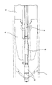
まず、発明者は、従来のデスケーリングを見直し、圧延前より圧延中に行なう方が、素管の変形によってスケールが剥離し易くなると考え、実験で確認することにした。しかも、素管の変形は、圧延ロールに噛み込んだ素管がプラグと接触する領域であることが望ましいので、以下のような継目無鋼管製造用治具を試作した。
【0015】
それは、図1に示すように、素管1を押し広げる砲弾のような形状をしたプラグ4と、該プラグ4を係止し、プラグ用冷却水を供給、排出させる流路を内部に設けた長尺のプラグ・バー(筒体)5とを備えた従来の継目無鋼管製造用治具に改良を加えたものである。つまり、前記プラグ・バー5には、前記プラグ4を貫通し、水7を先端側へ供給する流路6と、水7の供給手段(図示せず)を設けると共に、該プラグ4には、その前方位置で水7を後端方向、且つ斜め方向に噴射するノズル8を設けたのである。
【0016】
この治具を使用して素管の圧延をすると、先端から噴射された水7は、確実にプラグ4が素管1の内面と接触する位置若しくはその近傍に吹き付けられることになる。そして、その位置では、素管1が揉まれる状態になるので、変形が著しく起こり、スケール3の該素管内面からの剥離に多大な効果があると期待できた。また、プラグ4の前方へ水7を噴射するより、後方へ向ける方がはるかに効果があるとも考えられた。前方へ噴射した場合には、素管1の変形が小さいので、その効果は、圧延前のデスケーリングに近いと考えられるからである。
【0017】
なお、この治具では、プラグ4に設けたノズル8の水噴射角度は、特に限定しないことにした。圧延する素管1のサイズによって最も好ましい範囲があるからである。また、水7の供給手段は、公知のもので良いが、噴射時の水圧を種々変更できるように、0.51MPaの低圧から20.4MPaの高圧まで可能なものであることが好ましい。さらに、プラグ4は、通常、エロンゲータやリーラに用いられている公知の形状で良い。これらの圧延機で使用されるプラグ4の形状は、素材の穿孔用圧延機(ピアサ)のものと異なり、元々先端が鋭く尖っていないので、ノズルを取り付け易いからである。
【0018】
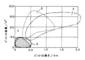
次に、この水7を斜め後方へ噴射するノズル8を取り付けた治具を用い、実際の製造工程で継目無鋼管を製造した。外径350mmの丸鋼鋳片を、ピアサで穿孔し、素管1とした。この素管1をエロンゲータで拡径、延伸のための圧延を施した。その際、表1に示す6つの条件でデスケーリング実験を行なった。すなわち、素管のデスケーリングをまったく行なわない場合、エロンゲータ上流の既設装置で行なう場合、及び試作した治具を用い、噴射水の圧力を種々変更した場合である。その他の圧延条件(素管温度、ロール圧下率、素管の移動速度等)は、いずれの場合も同じとした。そして、これらの実験を経た各素管1は、その後端300mmを切断して、図3に示すような試料9とし、内面をサンドブラストで研磨してから、内面状態を調査した。
【0019】
【表1】

その調査は、目視にてピットの個数を数えること、ピットの深さをデプスゲージ(深さ測定器)で測定することで行なわれた。その結果を、単位面積(cm2)当たりのピット個数及びピットの深さとの関係で整理し、図2に示す。図2より、デスケーリングを施さなかった場合(記号A),既設装置で行なった場合(記号B)に比べて、後方噴射式のノズルを用いた場合(水圧力が2.04MPaを記号C,15.31MPaを記号D)の方がはるかに、ピットの深さが浅く、またピット個数も少ないことが明らかである。すなわち、上記後方噴射式のノズル8を備えたプラグは、エロンゲータでの圧延において、素管1の拡径だけでなく、デスケーリングにも非常に有効であり、試作した治具及びそれを用いる継目無鋼管の製造方法は、十分に発明に価すると確認できた。そこで、本発明では、水7の噴射圧を0.51〜20.4MPaにすることが好ましいことした。0.51MPa未満では、デスケーリング効果が、エロンゲータ上流の既設装置で行なった程度であり、20.4MPa超えでは、効果が飽和するからである。特に、デスケーリングに、従来のような高圧水を用いないでも、2.04MPa程度の低圧で有効な効果が得られたことは、非常に注目されべきである。
【0021】
なお、プラグから前方への水噴射については、今回の実験では効果を確認していないが、図2の記号に近い効果が予想される。
【0022】
【実施例】
本発明に係る治具及び継目無鋼管の製造方法を用いて、鋼種が炭素鋼の外径185〜406mmφ,肉厚4.5〜35.0mmの継目無鋼管を多数製造した。製造工程は、素材である丸鋼鋳片を1200℃に加熱する加熱炉、素材を穿孔する圧延機(例えば、ピアサ)、得られた素管の拡径と肉厚を低減する圧延機(エロンゲータ)、肉厚を調整しながら延伸する圧延機(プラグミル)、偏肉矯正と磨管を行なう圧延機(リーラ)、素管の再加熱炉、外径を絞り定径する圧延機(サイザ)を直列に順次配置したものである。製造条件は、この鋼種、製品サイズに対して、通常採用されているものである。なお、効果の比較のため、デスケーリングを行なわない場合、及び既設装置を利用したデスケーリングを施した場合等、従来の方法でも実施した。
【0023】
得られた製品は、サンドブラストで内面のスケールを除去した後、該内面の粗度が測定された。その平均的な測定結果を図4に示す。図4より、本発明によれば、製品の内面粗度が従来に比べ非常に良くなっていることが明らかである。また、内面研磨は、本発明に係る製造方法で得た鋼管は、研磨作業が省略できたり、あるいは短時間で良く、研磨費用が従来に比べて大幅に低減できる効果もあった。さらに、製品の内面手入れ率(全製品数に対する手入れした数の割合)は、表2に示すように従来より低減し、製品歩留の向上も達成できた。
【0024】
【表2】
なお、上記実施例は、本発明に係る治具をエロンゲータに使用した場合で説明したが、それは、リーラで使用しても良い。同様にスケールが発生するからである。その際、エロンゲータと併用すれば、製品の内面肌は一層向上するものと予想できる。
【0026】
【発明の効果】
以上述べたように、本発明により、エロンゲータやリーラで素管を延伸圧延する際、圧延中に素管内面に存在するスケールを従来より良く除去できるようになる。その結果、研磨手入れを従来より減らしても、内面肌の良い継目無鋼管が製造できるようになった。
【図面の簡単な説明】
【図1】本発明に係る継目無鋼管製造用治具を示す縦断面図である。
【図2】図1の治具を使用した効果を確認した実験結果を示す図である。
【図3】製品内面状態を調査する試料の形状を示す図である。
【図4】製品内面の粗度を測定した結果を示す図である。
【図5】素管をエロンゲータで圧延中の状況を示す縦断面図である。
【符号の説明】
1 素管
2 ロール
3 スケール
4 プラグ
5 プラグ・バー(長尺の筒体)
6 流路
7 水
8 ノズル
9 試料[0001]
BACKGROUND OF THE INVENTION
The present invention relates to a seamless steel pipe manufacturing method and a seamless steel pipe manufacturing jig, and in particular, a rolling machine such as an elongator or a reeler that stretches and rolls a raw pipe obtained by drilling a round steel slab. It is a technology to manufacture seamless steel pipes with excellent inner surface quality by suppressing inner surface defects (commonly called avatar / pit defects) generated in the surface.
[0002]
[Prior art]
In general, seamless steel pipes are long, solid, round steel slabs (called round billets) with a circular cross-section, and they are advanced between rolling rolls to form a shell-shaped rolling aid. Manufactured by pressing a jig (called a plug), drilling, rolling, or adjusting the shape and dimensions using a perforated roll. Therefore, the manufacturing process is equipped with a plug, a rolling mill (for example, a piercer) that drills in the material, a rolling mill (elongator) that reduces the diameter and thickness of the obtained raw tube, and adjusts the wall thickness. Rolling machine (plug mill) that stretches while rolling, rolling machine (reeler) that performs uneven thickness correction and polishing pipe, and rolling machine (sizer, stretch reducer) that does not have a plug and reduces the outer diameter to a constant diameter. Has been placed.
[0003]
By the way, on the inner surface of the seamless steel pipe manufactured through this process, there is an inner surface defect mainly composed of an avatar / pit defect, which deteriorates the product quality. For this reason, a manufactured product usually requires a so-called “care work” in which the inner surface is polished with a tool or the like. Further, it is well known that the avatar / pit ridge is mainly formed of an elongator and a reeler, and the mechanism thereof is as follows.
[0004]
When the raw tube 1 as the material to be rolled is “empty” with the
[0005]
Therefore, before rolling an element pipe with an elongator or a reeler, the scale formed on the inner surface of the element pipe is removed by blowing high-pressure water (referred to as descaling). Recently, Japanese Patent Application Laid-Open No. 9-239409 discloses that high-pressure water is sprayed from the tip of a plug and the scale is removed while rolling the raw tube with an elongator.
[0006]
However, the inner scale of the raw tube is newly generated in a large amount even during rolling with an elongator or the like. This newly generated scale cannot be removed by the descaling before the rolling. Japanese Patent Laid-Open No. 9-239409 has a detailed disclosure of the configuration of an apparatus capable of removing scale during rolling. In other words, plug cooling water is used for locking and detachment between a plug and a plug bar (a long cylindrical body with a cooling water passage inside) connected to the plug, cooling water The main purpose is to additionally install a flow path for increasing the pressure. For this reason, there is no specific teaching about the method, conditions, and effects of descaling by jetting water from the plug tip.
[0007]
[Problems to be solved by the invention]
In view of such circumstances, the present invention, when extending and rolling an element tube with an elongator or a reeler, removes the scale existing on the inner surface of the element tube during rolling by injecting water at a lower pressure than before, and has a good inner skin. An object of the present invention is to provide a method for manufacturing a seamless steel pipe and a jig for manufacturing a seamless steel pipe.
[0008]
[Means for Solving the Problems]
The inventor conducted intensive studies and experiments in order to achieve the above object, and the results were embodied in the present invention.
[0009]
That is, the present invention relates to a method of manufacturing a seamless steel pipe in which a plug is inserted into a perforated element pipe, and the element pipe is stretched and diameter-rolled. In front of the plug inserted into the plug , water is removed from the tip end of the plug in the rear end direction and in an oblique direction to remove the inner scale of the raw tube at a pressure of 0.51 to 20.4 MPa . A method for producing a seamless steel pipe, wherein rolling is performed while spraying water on a rolling region of the inner surface of the raw pipe.
[0010]
Further, the present invention provides a method for producing a seamless steel pipe, wherein the water injection pressure is set to 0.51 to 3.06 MPa, or the stretching and diameter expansion rolling are performed by an elongator and / or a reeler. It is .
[0011]
Furthermore, the present invention is used when a perforated element tube is stretched and diameter-rolled and rolled, and a plug that contacts the inner surface of the element tube and spreads the element tube, locks the plug, and supplies cooling water to the plug. In a seamless steel pipe manufacturing jig provided with a long plug bar provided inside with a flow path to be supplied and discharged,
The plug bar passes through the plug and is provided with a flow path for supplying water to the front end side and a water supply means, and the plug has water in a rear end direction and an oblique direction at a front position thereof. A seamless steel pipe production comprising a nozzle for spraying water on a rolling region of an inner surface of a jetting element pipe , wherein the supply means is capable of changing a water injection pressure from 0.51 to 3.06 MPa. Jig. In this case, it is preferable that the supply means is capable of changing the water injection pressure from 0.51 to 20.4 MPa to 0.51 to 3.06 MPa.
[0012]
According to the present invention, when the raw pipe is stretched and rolled with an elongator or a reeler, the scale existing on the inner face of the raw pipe is sprayed in the rolling region during rolling, so the scale is easily peeled off due to deformation of the raw pipe. Therefore, it can be removed better than before. As a result, it has become possible to produce seamless steel pipes with good inner skin even if the polishing care is reduced as compared with the prior art.
[0013]
DETAILED DESCRIPTION OF THE INVENTION
Embodiments of the present invention will be described below with reference to the drawings.
[0014]
First, the inventor reconsidered the conventional descaling and thought that it would be easier for the scale to peel off due to deformation of the raw tube if it was performed during rolling than before rolling, and it was decided to confirm by experiments. In addition, since the deformation of the raw pipe is desirably in a region where the raw pipe bitten into the rolling roll comes into contact with the plug, the following seamless steel pipe manufacturing jig was manufactured as a prototype.
[0015]
As shown in FIG. 1, a plug 4 shaped like a bullet that pushes the raw tube 1 and a flow path for locking the plug 4 and supplying and discharging plug cooling water are provided inside. This is an improvement to a conventional seamless steel pipe manufacturing jig provided with a long plug bar (tubular body) 5. That is, the
[0016]
When the raw tube is rolled using this jig, the water 7 sprayed from the tip is surely sprayed at a position where the plug 4 contacts the inner surface of the raw tube 1 or in the vicinity thereof. At that position, the raw tube 1 is in a state of being entrained, so that deformation occurs significantly, and it can be expected that the scale 3 is peeled off from the inner surface of the raw tube. Moreover, it was thought that the direction which turned back rather than spraying the water 7 ahead of the plug 4 was much more effective. This is because the deformation of the raw tube 1 is small when sprayed forward, and the effect is considered to be close to descaling before rolling.
[0017]
In this jig, the water injection angle of the
[0018]
Next, a seamless steel pipe was manufactured in an actual manufacturing process using a jig provided with a
[0019]
[Table 1]
The investigation was carried out by counting the number of pits visually and measuring the depth of the pits with a depth gauge. The results are organized in relation to the number of pits per unit area (cm 2 ) and the pit depth, and are shown in FIG. From FIG. 2, when descaling was not performed (symbol A), compared with the case where the existing apparatus was used (symbol B), a rear injection type nozzle was used (water pressure was 2.04 MPa, symbol C, It is clear that 15.31 MPa is marked by the symbol D), which has a much smaller pit depth and a smaller number of pits. That is, the plug provided with the above-described rear
[0021]
In addition, about the water injection from a plug ahead, although the effect is not confirmed in this experiment, the effect close | similar to the symbol of FIG. 2 is anticipated.
[0022]
【Example】
A number of seamless steel pipes having an outer diameter of 185 to 406 mmφ and a wall thickness of 4.5 to 35.0 mm of carbon steel were produced using the jig and the method for producing seamless steel pipes according to the present invention. The manufacturing process consists of a heating furnace that heats the round steel slab as a raw material to 1200 ° C., a rolling mill that pierces the raw material (for example, a piercer), and a rolling mill that reduces the diameter and thickness of the resulting raw tube (elongator) ), A rolling mill (plug mill) that stretches while adjusting the wall thickness, a rolling mill that performs uneven thickness correction and polishing pipe (reeler), a reheating furnace for the raw pipe, and a rolling mill (sizer) that squeezes the outer diameter. They are sequentially arranged in series. The manufacturing conditions are usually employed for this steel type and product size. For comparison of the effect, the conventional method was also used such as when descaling was not performed and when descaling was performed using an existing device.
[0023]
The obtained product was subjected to sand blasting to remove scale on the inner surface, and then the roughness of the inner surface was measured. The average measurement result is shown in FIG. From FIG. 4, it is clear that according to the present invention, the inner surface roughness of the product is much better than the conventional one. Further, the inner surface polishing has the effect that the steel pipe obtained by the manufacturing method according to the present invention can omit the polishing operation or can be performed in a short time, and the polishing cost can be greatly reduced as compared with the conventional method. Furthermore, as shown in Table 2, the inner surface maintenance rate of the product (ratio of the number of maintenance to the total number of products) was reduced as compared with the prior art, and the product yield was improved.
[0024]
[Table 2]
In addition, although the said Example demonstrated the case where the jig | tool based on this invention was used for an elongator, it may be used with a reeler. This is because the scale is generated similarly. At that time, if it is used in combination with an elongator, the inner skin of the product can be expected to be further improved.
[0026]
【The invention's effect】
As described above, according to the present invention, when the raw pipe is stretch-rolled with an elongator or a reeler, scale existing on the inner face of the raw pipe during rolling can be removed better than before. As a result, it has become possible to produce seamless steel pipes with good inner skin even if the polishing care is reduced as compared with the prior art.
[Brief description of the drawings]
FIG. 1 is a longitudinal sectional view showing a seamless steel pipe manufacturing jig according to the present invention.
FIG. 2 is a diagram showing experimental results for confirming the effect of using the jig of FIG.
FIG. 3 is a diagram showing the shape of a sample for examining the inner surface state of a product.
FIG. 4 is a diagram showing the result of measuring the roughness of the inner surface of the product.
FIG. 5 is a longitudinal sectional view showing a state in which a raw tube is being rolled by an elongator.
[Explanation of symbols]
1
6 Channel 7
Claims (5)
前記素管の延伸、拡径圧延中に、該素管に挿入したプラグより前方位置で、該プラグの先端から後端方向、旦つ斜め方向に、素管の内面スケールを除去する水を、噴射時の圧力を0.51〜20.4MPaとして噴射し、素管内面の圧延領域に水を吹き付けながら圧延することを特徴とする継目無鋼管の製造方法。In a method for producing a seamless steel pipe, in which a plug is inserted into a drilled base pipe, the base pipe is stretched, and diameter-expanded and rolled,
During drawing and diameter expansion rolling of the pipe, water for removing the inner scale of the pipe at a position forward from the plug inserted into the pipe, from the front end of the plug to the rear end direction, and in an oblique direction , A method for producing a seamless steel pipe, characterized in that the pressure at the time of jetting is 0.51 to 20.4 MPa and the steel pipe is rolled while spraying water on the rolling area of the inner surface of the raw pipe.
前記素管の延伸、拡径圧延中に、該素管に挿入したプラグより前方位置で、プラグの先端から後端方向、且つ斜め方向に、素管の内面スケールを除去する水を、噴射時の圧力を0.51〜3.06MPaとして噴射し、素管内面の圧延領域に水を吹き付けながら圧延することを特徴とする継目無鋼管の製造方法。 In a method for producing a seamless steel pipe, in which a plug is inserted into a drilled base pipe, the base pipe is stretched, and diameter-expanded and rolled,
During the injection and expansion of the raw pipe, water for removing the inner scale of the raw pipe from the front end of the plug to the rear end direction and in an oblique direction at a position ahead of the plug inserted into the raw pipe. pressure injecting as 0.51~3.06MPa, manufacturing method of splicing first steel pipe you characterized by rolling while spraying water to the rolling region of the element inner surface of.
前記プラグ・バーには、前記プラグを貫通し、水を先端側へ供給する流路と、水の供給手段を設けると共に、該プラグには、その前方位置で水を後端方向、且つ斜め方向に噴射し素管の内面の圧延領域に水を吹き付けるノズルを設けてなり、
前記供給手段が、水の噴射圧力を0.51〜20.4MPaまで変更自在であることを特徴とする継目無鋼管製造用治具。 Used when stretching and diameter-rolling a drilled element tube, a plug that comes into contact with the inner surface of the element tube and expands the element tube, and a channel that locks the plug and supplies and discharges cooling water for the plug. In a seamless steel pipe manufacturing jig provided with a long plug bar provided inside,
The plug bar passes through the plug and is provided with a flow path for supplying water to the front end side and water supply means, and the plug has water at the front position in the rear end direction and in an oblique direction. And a nozzle that sprays water on the inner surface of the base tube and sprays water on it.
Said supply means, welt steel pipe manufacturing jig you being a freely change the injection pressure of the water to 0.51~20.4MPa.
前記プラグ・バーには、前記プラグを貫通し、水を先端側へ供給する流路と、水の供給手段を設けると共に、該プラグには、その前方位置で水を後端方向、且つ斜め方向に噴射し素管の内面の圧延領域に水を吹き付けるノズルを設けてなり、
前記供給手段が、水の噴射圧力を0.51〜3.06MPaまで変更自在であることを特徴とする継目無鋼管製造用治具。Used when stretching and diameter-rolling a drilled element tube, a plug that comes into contact with the inner surface of the element tube and expands the element tube, and a channel that locks the plug and supplies and discharges cooling water for the plug. In a seamless steel pipe manufacturing jig provided with a long plug bar provided inside,
The plug bar passes through the plug and is provided with a flow path for supplying water to the front end side and water supply means, and the plug has water at the front position in the rear end direction and in an oblique direction. And a nozzle that sprays water on the inner surface of the base tube and sprays water on it.
The jig for manufacturing a seamless steel pipe , wherein the supplying means is capable of changing a water injection pressure from 0.51 to 3.06 MPa .
Priority Applications (1)
| Application Number | Priority Date | Filing Date | Title |
|---|---|---|---|
| JP2000014176A JP4356168B2 (en) | 2000-01-20 | 2000-01-20 | Seamless steel pipe manufacturing method and seamless steel pipe manufacturing jig |
Applications Claiming Priority (1)
| Application Number | Priority Date | Filing Date | Title |
|---|---|---|---|
| JP2000014176A JP4356168B2 (en) | 2000-01-20 | 2000-01-20 | Seamless steel pipe manufacturing method and seamless steel pipe manufacturing jig |
Publications (3)
| Publication Number | Publication Date |
|---|---|
| JP2001205328A JP2001205328A (en) | 2001-07-31 |
| JP2001205328A5 JP2001205328A5 (en) | 2006-12-28 |
| JP4356168B2 true JP4356168B2 (en) | 2009-11-04 |
Family
ID=18541667
Family Applications (1)
| Application Number | Title | Priority Date | Filing Date |
|---|---|---|---|
| JP2000014176A Expired - Fee Related JP4356168B2 (en) | 2000-01-20 | 2000-01-20 | Seamless steel pipe manufacturing method and seamless steel pipe manufacturing jig |
Country Status (1)
| Country | Link |
|---|---|
| JP (1) | JP4356168B2 (en) |
Families Citing this family (5)
| Publication number | Priority date | Publication date | Assignee | Title |
|---|---|---|---|---|
| JP2008221250A (en) * | 2007-03-09 | 2008-09-25 | Sumitomo Metal Ind Ltd | Method for producing seamless steel tube |
| CN103909105B (en) * | 2014-03-28 | 2016-10-05 | 宝山钢铁股份有限公司 | The inner wall of metal tube mixing jet descaling device of one axially eccentric arrangement |
| CN108067502B (en) * | 2017-11-29 | 2023-06-27 | 鑫鹏源智能装备集团有限公司 | Antioxidant conveying device in hot rolling seamless pipe rolling process and use method thereof |
| CN107900118B (en) * | 2017-12-22 | 2023-06-23 | 鑫鹏源智能装备集团有限公司 | Rotary joint for seamless pipe hot rolling process trolley |
| CN112718868A (en) * | 2020-12-10 | 2021-04-30 | 太原重工股份有限公司 | System and process for eliminating pockmarks on inner surface of hot rotary expansion steel pipe |
-
2000
- 2000-01-20 JP JP2000014176A patent/JP4356168B2/en not_active Expired - Fee Related
Also Published As
| Publication number | Publication date |
|---|---|
| JP2001205328A (en) | 2001-07-31 |
Similar Documents
| Publication | Publication Date | Title |
|---|---|---|
| JP4356168B2 (en) | Seamless steel pipe manufacturing method and seamless steel pipe manufacturing jig | |
| JPH06269839A (en) | Descaling method and rolling method for slab | |
| JPH09271811A (en) | Method for manufacturing seamless steel pipe made of duplex stainless steel | |
| JP2586274B2 (en) | Method for manufacturing seamless steel pipe of chromium-containing iron-based alloy | |
| JPH06126323A (en) | Method for descaling inside surface of seamless steel pipe | |
| JPS58168404A (en) | Rolling method of pipe in second piercer | |
| JP2705499B2 (en) | Manufacturing method of hot seamless carbon steel pipe | |
| JPS60130406A (en) | Method and device for manufacturing seamless steel pipe | |
| JPH06104243B2 (en) | Titanium seamless pipe manufacturing method | |
| JP4117955B2 (en) | Billet drilling method | |
| JPS5937281Y2 (en) | Plug device for pipe rolling mill | |
| JPH05185132A (en) | Method for rolling seamless steel tube | |
| JPH05185131A (en) | Production of seamless stainless steel pipe | |
| JP2011115851A (en) | Method of manufacturing seamless steel pipe | |
| JPH06198311A (en) | Piercing method and piercing mill | |
| JP3785916B2 (en) | Rolling method for seamless metal pipe | |
| JPH0824911A (en) | Expansion rolling device for seamless tube | |
| JPS58168405A (en) | Rolling method of pipe in second piercer | |
| JPH06210321A (en) | Plug for rolling seamless steel tube with descaling brush | |
| JP5277909B2 (en) | Billet piercing and rolling method | |
| JP2586246B2 (en) | Manufacturing method of hot seamless steel pipe | |
| JPH0615343A (en) | Method for descaling rolled stock for seamless steel tube | |
| JPH05245527A (en) | Method for improving quality of inner surface of hot seamless steel tube and mandrel mill | |
| JPH1015604A (en) | Method for rolling high alloy seamless steel tube | |
| JPH10128427A (en) | Descaling method in outer surface of seamless steel tube |
Legal Events
| Date | Code | Title | Description |
|---|---|---|---|
| A621 | Written request for application examination |
Free format text: JAPANESE INTERMEDIATE CODE: A621 Effective date: 20061026 |
|
| A521 | Written amendment |
Free format text: JAPANESE INTERMEDIATE CODE: A523 Effective date: 20061110 |
|
| A977 | Report on retrieval |
Free format text: JAPANESE INTERMEDIATE CODE: A971007 Effective date: 20071217 |
|
| A131 | Notification of reasons for refusal |
Free format text: JAPANESE INTERMEDIATE CODE: A131 Effective date: 20071225 |
|
| A521 | Written amendment |
Free format text: JAPANESE INTERMEDIATE CODE: A523 Effective date: 20080222 |
|
| A131 | Notification of reasons for refusal |
Free format text: JAPANESE INTERMEDIATE CODE: A131 Effective date: 20090310 |
|
| A521 | Written amendment |
Free format text: JAPANESE INTERMEDIATE CODE: A523 Effective date: 20090508 |
|
| TRDD | Decision of grant or rejection written | ||
| A01 | Written decision to grant a patent or to grant a registration (utility model) |
Free format text: JAPANESE INTERMEDIATE CODE: A01 Effective date: 20090714 |
|
| A01 | Written decision to grant a patent or to grant a registration (utility model) |
Free format text: JAPANESE INTERMEDIATE CODE: A01 |
|
| A61 | First payment of annual fees (during grant procedure) |
Free format text: JAPANESE INTERMEDIATE CODE: A61 Effective date: 20090727 |
|
| FPAY | Renewal fee payment (event date is renewal date of database) |
Free format text: PAYMENT UNTIL: 20120814 Year of fee payment: 3 |
|
| R150 | Certificate of patent or registration of utility model |
Ref document number: 4356168 Country of ref document: JP Free format text: JAPANESE INTERMEDIATE CODE: R150 Free format text: JAPANESE INTERMEDIATE CODE: R150 |
|
| FPAY | Renewal fee payment (event date is renewal date of database) |
Free format text: PAYMENT UNTIL: 20120814 Year of fee payment: 3 |
|
| FPAY | Renewal fee payment (event date is renewal date of database) |
Free format text: PAYMENT UNTIL: 20130814 Year of fee payment: 4 |
|
| LAPS | Cancellation because of no payment of annual fees |