JP4347389B2 - Game machine - Google Patents
Game machine Download PDFInfo
- Publication number
- JP4347389B2 JP4347389B2 JP2008053970A JP2008053970A JP4347389B2 JP 4347389 B2 JP4347389 B2 JP 4347389B2 JP 2008053970 A JP2008053970 A JP 2008053970A JP 2008053970 A JP2008053970 A JP 2008053970A JP 4347389 B2 JP4347389 B2 JP 4347389B2
- Authority
- JP
- Japan
- Prior art keywords
- value
- random
- determination
- game
- counter
- Prior art date
- Legal status (The legal status is an assumption and is not a legal conclusion. Google has not performed a legal analysis and makes no representation as to the accuracy of the status listed.)
- Expired - Lifetime
Links
Images


Description
本発明は、遊技者が所定の遊技を行い、特定の条件成立に応じて遊技者にとって有利な特定遊技状態に制御可能なパチンコ遊技機等の遊技機に関する。 The present invention relates to a gaming machine such as a pachinko gaming machine in which a player plays a predetermined game and can be controlled to a specific gaming state advantageous to the player when a specific condition is established.
遊技機として、遊技球などの遊技媒体を発射装置によって遊技領域に発射し、遊技領域に設けられている入賞口などの入賞領域に遊技媒体が入賞すると、所定個の賞球が遊技者に払い出されるものがある。さらに、遊技が行われているときに所定の条件が成立した場合に所定の遊技価値を遊技者に与えるように構成されたものがある。遊技価値とは、例えば、遊技機の遊技領域に設けられた可変入賞球装置の状態が打球が入賞しやすい遊技者にとって有利な状態になることや、遊技者にとって有利な状態となるための権利を発生させたりすることや、賞球払出の条件が成立しやすくなる状態になることである。 As a gaming machine, a game medium such as a game ball is launched into a game area by a launching device, and when a game medium wins a prize area such as a prize opening provided in the game area, a predetermined number of prize balls are paid out to the player. There is something to be done. Further, there is a configuration in which a predetermined game value is given to a player when a predetermined condition is satisfied when a game is being performed. The game value is, for example, the right that the state of the variable winning ball apparatus provided in the gaming area of the gaming machine is advantageous to a player who is easy to win, and the right to be advantageous to the player. In other words, or a condition for winning a prize ball is easily established.
パチンコ遊技機等では、遊技者にとって有利な状態として、多数の景品球等が遊技者に付与される可能性がある特定遊技状態(大当り遊技状態)があるが、そのような遊技機における遊技制御においては、所定の条件が成立すると乱数を発生させ、乱数値があらかじめ決まられている大当り判定値と一致すると「大当り」とすることに決定される。乱数値は、一般に、定期的にカウントアップされカウント値が最大値を越えると初期値に戻るカウンタのカウント値を抽出することによって得られる。 In pachinko machines, etc., there is a specific gaming state (big hit gaming state) in which a large number of prize balls may be given to the player as an advantageous state for the player. In this case, when a predetermined condition is satisfied, a random number is generated, and when the random number value matches a predetermined jackpot determination value, it is determined to be “big hit”. The random value is generally obtained by extracting the count value of a counter that is periodically counted up and returns to the initial value when the count value exceeds the maximum value.
カウンタのカウント値は定期的にカウントアップされるので、何らかの手段でカウントアップの周期やカウンタのカウント値が1周する周期が検出されると、大当り判定値と一致する乱数値を発生するタイミングが認識されてしまう。すると、大当り判定値と一致する乱数値が発生するタイミングを狙った遊技を行うことによって、頻繁に「大当り」を発生させることが可能になってしまう。大当り判定値と一致する乱数値が発生するタイミングを狙うために、遊技機に不正基板が取り付けられる場合がある。そのような不正基板は遊技制御を行う回路部分から外部に出力される信号を導入し、その信号にもとづいて遊技制御を行う回路部分の起動タイミングを検出し、大当り判定値と一致する乱数値が発生するタイミングを検出している。そして、不正基板は、そのタイミングで遊技制御を行う回路部分に所定の信号を送り「大当り」を不正に発生させることが可能になる。その結果、遊技機を設置している遊技店に不利益が生じてしまう。 Since the count value of the counter is periodically counted up, the timing for generating a random value that matches the jackpot determination value is detected when the count-up cycle or the cycle in which the counter count value makes one round is detected by some means. It will be recognized. Then, it is possible to frequently generate “hit” by playing a game aimed at the timing at which a random number value that matches the jackpot determination value is generated. In some cases, an illegal board is attached to a gaming machine in order to aim at a timing at which a random number value that matches the jackpot value is generated. Such a fraudulent board introduces a signal output to the outside from the circuit part that performs game control, detects the start timing of the circuit part that performs game control based on the signal, and the random value that matches the jackpot determination value is The timing of occurrence is detected. Then, the illegal board can send a predetermined signal to the circuit portion that controls the game at that timing, and illegally generate a “big hit”. As a result, there is a disadvantage in the game store where the gaming machine is installed.
「大当り」を生じさせる乱数値の発生をねらった不正信号による不正行為を防止するために、カウント値が最大値に達すると、カウント値を特定の値に戻すのではなく、ランダムな値に戻すようにすることが提案されている。そのようなカウンタ制御を行えば、外部から「大当り」を生じさせる乱数値の発生を狙うことが難しくなる。 In order to prevent fraudulent acts due to fraudulent signals aiming at the generation of random numbers that cause “big hits”, when the count value reaches the maximum value, the count value is returned to a random value instead of returning to a specific value. It has been proposed to do so. If such counter control is performed, it is difficult to aim at generation of a random value that causes a “big hit” from the outside.
上述したように、特定遊技状態を生じさせる乱数値の発生を狙った不正信号による不正行為を防止するための対策が施されている。しかし、遊技機には特定遊技状態とするか否かを決定するために用いられる乱数の他に種々の乱数が用いられ、乱数値が所定の値に一致すると遊技者にとって有利な状態になるように遊技機が構成されているが、それらの乱数に対して十分な対策が施されていない。 As described above, measures are taken to prevent fraudulent acts caused by fraudulent signals aimed at generating random values that cause a specific gaming state. However, in the gaming machine, various random numbers are used in addition to the random number used for determining whether or not to enter a specific gaming state, and if the random number value matches a predetermined value, it will be in an advantageous state for the player. Although gaming machines are configured, sufficient measures are not taken against these random numbers.
そこで、本発明は、特定遊技状態とするか否かを決定するために用いられる数値以外の数値についても、数値が所定の値に一致するタイミングを遊技機外部から特定することを困難にすることができる遊技機を提供することを目的とする。 Therefore, the present invention makes it difficult to specify from the outside of the gaming machine the timing at which the numerical value matches a predetermined value for numerical values other than those used to determine whether or not to enter a specific gaming state. An object is to provide a gaming machine that can be used.
本発明による遊技機は、各々を識別可能な複数種類の普通識別情報を可変表示可能な普通可変表示部と、普通可変表示部における表示態様があらかじめ定められた所定の表示態様となったときに遊技者にとって有利な状態に制御される普通可変入賞装置と、該普通可変入賞装置と別に設けられ、遊技者にとって有利な状態に制御される特別可変入賞装置とを備え、特定の条件成立に応じて、特別可変入賞装置が有利な状態に制御されるラウンドを所定のラウンド回数まで実行可能な特定遊技状態に制御可能な遊技機であって、制御を行う際に発生する変動データを記憶するRAMを有し、遊技の進行を制御する遊技制御手段を備え、遊技制御手段は、初期設定処理を行った後、所定の処理を繰り返し実行するメインルーチンと、メインルーチン実行中に所定時間毎に発生するタイマ割込に応じてメインルーチンを中断して起動される割込ルーチンとを実行する実行手段を備え、実行手段は、割込ルーチンにおいて、ラウンド回数を決定するためのラウンド回数決定用数値を第1の範囲内で更新するラウンド回数決定用数値更新処理と、普通可変表示部にて所定の表示態様を表示するか否かを決定するための普通可変表示決定用数値を第2の範囲内で更新する普通可変表示決定用数値更新処理と、第1のタイミングでラウンド回数決定用数値の更新の初期値をRAMに格納されているラウンド回数初期値用数値に変更するラウンド回数初期値変更処理と、第2のタイミングで普通可変表示決定用数値の更新の初期値をRAMに格納されている普通可変表示初期値用数値に変更する普通可変表示初期値変更処理とを含む遊技制御処理を実行するとともに、メインルーチンにおいて、所定の処理として、RAMに格納されているラウンド回数初期値用数値を更新するラウンド回数初期値用数値更新処理と、RAMに格納されている普通可変表示初期値用数値を更新する普通可変表示初期値用数値更新処理とを実行し、メインルーチンにおけるラウンド回数初期値用数値更新処理および普通可変表示初期値用数値更新処理を開始する前にタイマ割込による割込を禁止し、ラウンド回数初期値用数値更新処理および普通可変表示初期値用数値更新処理の完了後にタイマ割込による割込を許可することを特徴とする。 The gaming machine according to the present invention has a normal variable display unit that can variably display a plurality of types of normal identification information that can be identified, and a display mode in the normal variable display unit that is a predetermined display mode. Provided with a normal variable winning device controlled in a state advantageous to the player and a special variable winning device provided separately from the normal variable winning device and controlled in a state advantageous to the player , according to the establishment of a specific condition A game machine capable of controlling a special game state in which a special variable winning device is controlled to an advantageous state to a specific game state that can be executed up to a predetermined number of rounds, and storing variation data generated when the control is performed And a game control means for controlling the progress of the game, the game control means comprising: a main routine for repeatedly executing a predetermined process after performing an initial setting process; and a main routine Execution means for executing an interrupt routine that is activated by interrupting the main routine in response to a timer interrupt that occurs every predetermined time during execution, and the execution means determines the number of rounds in the interrupt routine Round number determination numerical value update processing for updating the round number determination numerical value for the first range within the first range, and normal variable display determination for determining whether or not to display a predetermined display mode on the normal variable display unit The numerical value update process for determining the normal variable display for updating the numerical value for use within the second range, and the initial value for updating the numerical value for determining the round number at the first timing is used as the initial value for the round number initial value stored in the RAM. A process for changing the initial value of the number of rounds to be changed and the initial value for updating the numerical value for determining the normal variable display at the second timing is changed to the numerical value for the normal variable display initial value stored in the RAM. A game control process including a change display initial value change process, and a round number initial value numerical value update process for updating a round number initial value numerical value stored in the RAM as a predetermined process in the main routine; The normal variable display initial value numerical value updating process for updating the normal variable display initial value numerical value stored in the RAM is executed, and the round number initial value numerical value updating process and the normal variable display initial value numerical value in the main routine are executed. Interrupts by timer interrupts are prohibited before starting update processing, and interrupts by timer interrupts are permitted after completion of the numerical value update processing for round count initial values and numerical value update processing for normal variable display initial values And
本発明の好ましい態様では、遊技機を、制御を行う際に発生する変動データを記憶するRAMを有し、遊技の進行を制御する遊技制御手段を備え、遊技制御手段が、初期設定処理を行った後、所定の処理を繰り返し実行するメインルーチンと、メインルーチン実行中に所定時間毎に発生するタイマ割込に応じてメインルーチンを中断して起動される割込ルーチンとを実行する実行手段を備え、実行手段が、割込ルーチンにおいて、ラウンド回数を決定するためのラウンド回数決定用数値を第1の範囲内で更新するラウンド回数決定用数値更新処理と、普通可変表示部にて所定の表示態様を表示するか否かを決定するための普通可変表示決定用数値を第2の範囲内で更新する普通可変表示決定用数値更新処理と、第1のタイミングでラウンド回数決定用数値の更新の初期値をRAMに格納されているラウンド回数初期値用数値に変更するラウンド回数初期値変更処理と、第2のタイミングで普通可変表示決定用数値の更新の初期値をRAMに格納されている普通可変表示初期値用数値に変更する普通可変表示初期値変更処理とを含む遊技制御処理を実行するとともに、メインルーチンにおいて、所定の処理として、RAMに格納されているラウンド回数初期値用数値を更新するラウンド回数初期値用数値更新処理と、RAMに格納されている普通可変表示初期値用数値を更新する普通可変表示初期値用数値更新処理とを実行し、メインルーチンにおけるラウンド回数初期値用数値更新処理および普通可変表示初期値用数値更新処理を開始する前にタイマ割込による割込を禁止し、ラウンド回数初期値用数値更新処理および普通可変表示初期値用数値更新処理の完了後にタイマ割込による割込を許可する構成にしたので、ラウンド回数の決定に用いられるラウンド回数決定用数値や普通可変表示決定用数値の更新のタイミングを遊技機外部から特定することを困難にすることができ、不正行為を効果的に防止することができる効果がある。 In a preferred aspect of the present invention, the gaming machine has a RAM for storing variable data generated when the control is performed, and includes a game control means for controlling the progress of the game, and the game control means performs an initial setting process. And an execution means for executing a main routine that repeatedly executes a predetermined process and an interrupt routine that is activated by interrupting the main routine in response to a timer interrupt that occurs every predetermined time during the execution of the main routine. A number of rounds determination numerical value update processing for updating the round number determination numerical value for determining the number of rounds within the first range in the interrupt routine, and a predetermined display on the normal variable display unit A normal variable display determination numerical value updating process for updating the normal variable display determination numerical value for determining whether or not to display the aspect within the second range, and round times at the first timing. The round number initial value changing process for changing the initial value for updating the numerical value for determination to the numerical value for the round number initial value stored in the RAM, and the initial value for updating the numerical value for determining the normally variable display at the second timing are stored in the RAM. The game control process including the normal variable display initial value changing process for changing to the normal variable display initial value value stored in the main routine is executed, and the number of rounds stored in the RAM as a predetermined process in the main routine The number of rounds initial value updating process for updating the initial value numerical value and the normal variable display initial value updating process for updating the normal variable display initial value stored in the RAM are executed in the main routine. Before starting the numerical update process for the initial value of the number of rounds and the numerical value update process for the normal variable display initial value, interrupts by timer interrupts are prohibited. Having after completion of de numeric for count initial value update processing and common variable display initial value for numerical updating the configuration to allow interruption by the timer interrupt, the round number determination for numerical and ordinary variable used to determine the number of rounds It is possible to make it difficult to specify the timing for updating the display determination numerical value from the outside of the gaming machine, and it is possible to effectively prevent fraud.
実施の形態1.
以下、本発明の一実施形態を図面を参照して説明する。
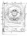
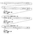
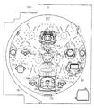
まず、遊技機の一例である第1種パチンコ遊技機の全体の構成について説明する。図1はパチンコ遊技機を正面からみた正面図、図2は遊技盤の前面を示す正面図である。
Hereinafter, an embodiment of the present invention will be described with reference to the drawings.
First, the overall configuration of a first type pachinko gaming machine that is an example of a gaming machine will be described. FIG. 1 is a front view of a pachinko gaming machine as viewed from the front, and FIG. 2 is a front view showing the front of the game board.
パチンコ遊技機1は、縦長の方形状に形成された外枠(図示せず)と、外枠の内側に開閉可能に取り付けられた遊技枠とで構成される。また、パチンコ遊技機1は、遊技枠に開閉可能に設けられている額縁状に形成されたガラス扉枠2を有する。遊技枠は、外枠に対して開閉自在に設置される前面枠(図示せず)と、機構部品等が取り付けられる機構板と、それらに取り付けられる種々の部品(後述する遊技盤を除く。)とを含む構造体である。
The
図1に示すように、パチンコ遊技機1は、額縁状に形成されたガラス扉枠2を有する。ガラス扉枠2の下部表面には打球供給皿(上皿)3がある。打球供給皿3の下部には、打球供給皿3に収容しきれない遊技球を貯留する余剰球受皿4と打球を発射する打球操作ハンドル(操作ノブ)5が設けられている。ガラス扉枠2の背面には、遊技盤6が着脱可能に取り付けられている。なお、遊技盤6は、それを構成する板状体と、その板状体に取り付けられた種々の部品とを含む構造体である。また、遊技盤6の前面には遊技領域7が形成されている。
As shown in FIG. 1, the
遊技領域7の中央付近には、それぞれが識別情報としての図柄を可変表示する複数の可変表示部を含む可変表示装置(特別可変表示装置)9が設けられている。可変表示装置9には、例えば「左」、「中」、「右」の3つの可変表示部(図柄表示エリア)がある。可変表示装置9の下方には、始動入賞口14が設けられている。始動入賞口14に入った入賞球は、遊技盤6の背面に導かれ、始動口スイッチ14aによって検出される。また、始動入賞口14の下部には開閉動作を行う可変入賞球装置15が設けられている。可変入賞球装置15は、ソレノイド16によって開状態とされる。
Near the center of the
可変入賞球装置15の下部には、特定遊技状態(大当り状態)においてソレノイド21によって開状態とされる開閉板20が設けられている可変入賞球装置24が設置されている。開閉板20は大入賞口を開閉する手段である。開閉板20から遊技盤6の背面に導かれた入賞球のうち一方(特定領域としてのV入賞領域)に入った入賞球はV入賞スイッチ22で検出され、開閉板20からの入賞球はカウントスイッチ23で検出される。遊技盤6の背面には、大入賞口内の経路を切り換えるためのソレノイド21Aも設けられている。また、可変表示装置9の下部には、始動入賞口14に入った有効入賞球数すなわち始動記憶数を表示する4つのLEDによる特別図柄始動記憶表示器(以下、始動記憶表示器という。)18が設けられている。有効始動入賞がある毎に、始動記憶表示器18は点灯するLEDを1増やす。そして、可変表示装置9の可変表示が開始される毎に、点灯するLEDを1減らす。
A variable winning
ゲート32に遊技球が入賞しゲートスイッチ32aで検出されると、普通図柄始動記憶が上限に達していなければ、所定の乱数値が抽出される。そして、普通図柄表示器10において表示状態が変化する可変表示を開始できる状態であれば、普通図柄表示器10の表示の可変表示が開始される。普通図柄表示器10において表示状態が変化する可変表示を開始できる状態でなければ、普通図柄始動記憶の値が1増やされる。普通図柄表示器10の近傍には、普通図柄始動記憶数を表示する4つのLEDによる表示部を有する普通図柄始動記憶表示器41が設けられている。ゲート32への入賞がある毎に、普通図柄始動記憶表示器41は点灯するLEDを1増やす。そして、普通図柄表示器10の可変表示が開始される毎に、点灯するLEDを1減らす。なお、特別図柄と普通図柄とを一つの可変表示装置で可変表示するように構成することもできる。その場合には、特別可変表示部と普通可変表示部とは1つの可変表示装置で実現される。
When a game ball wins the
この実施の形態では、左右のランプ(点灯時に図柄が視認可能になる)が交互に点灯することによって可変表示が行われ、可変表示は所定時間(例えば29秒)継続する。そして、可変表示の終了時に左側のランプが点灯すれば当りとなる。当りとするか否かは、ゲート32に遊技球が入賞したときに抽出された乱数の値が所定の当り判定値と一致したか否かによって決定される。普通図柄表示器10における可変表示の表示結果が当りである場合に、可変入賞球装置15が所定回数、所定時間だけ開状態になって遊技球が入賞しやすい状態になる。すなわち、可変入賞球装置15の状態は、普通図柄の停止図柄が当り図柄である場合に、遊技者にとって不利な状態から有利な状態に変化する。
In this embodiment, the left and right lamps (designs can be visually recognized when lit) are alternately lit to perform variable display, and the variable display continues for a predetermined time (for example, 29 seconds). If the left lamp is turned on at the end of the variable display, it is a win. Whether or not to win is determined by whether or not the value of the random number extracted when the game ball wins the
さらに、確変状態では、普通図柄表示器10における停止図柄が当り図柄になる確率が高められるとともに、可変入賞球装置15の開放時間と開放回数とのうちの一方または双方が高められ、遊技者にとってさらに有利になる。また、確変状態等の所定の状態では、普通図柄表示器10における可変表示期間(変動時間)が短縮されることによって、遊技者にとってさらに有利になるようにしてもよい。
Further, in the probability variation state, the probability that the stop symbol in the
遊技盤6には、複数の入賞口29,30,33,39が設けられ、遊技球の入賞口29,30,33への入賞は、それぞれ入賞口スイッチ29a,30a,33a,39aによって検出される。遊技領域7の左右周辺には、遊技中に点滅表示される装飾ランプ25が設けられ、下部には、入賞しなかった打球を吸収するアウト口26がある。また、遊技領域7の外側の左右上部には、効果音を発する2つのスピーカ27が設けられている。遊技領域7の外周には、天枠ランプ28a、左枠ランプ28bおよび右枠ランプ28cが設けられている。さらに、遊技領域7における各構造物(大入賞口等)の周囲には装飾LEDが設置されている。天枠ランプ28a、左枠ランプ28bおよび右枠ランプ28cおよび装飾用LEDは、遊技機に設けられている装飾発光体の一例である。
The
そして、この例では、左枠ランプ28bの近傍に、賞球残数があるときに点灯する賞球ランプ51が設けられ、天枠ランプ28aの近傍に、補給球が切れたときに点灯する球切れランプ52が設けられている。さらに、図1には、パチンコ遊技機1に隣接して設置され、プリペイドカードが挿入されることによって球貸しを可能にするカードユニット50も示されている。
In this example, a prize ball lamp 51 that is turned on when there is a remaining number of prize balls is provided in the vicinity of the
カードユニット50には、使用可能状態であるか否かを示す使用可表示ランプ151、カードユニット50がいずれの側のパチンコ遊技機1に対応しているのかを示す連結台方向表示器153、カードユニット50内にカードが投入されていることを示すカード投入表示ランプ154、記録媒体としてのカードが挿入されるカード挿入口155、およびカード挿入口155の裏面に設けられているカードリーダライタの機構を点検する場合にカードユニット50を解放するためのカードユニット錠156が設けられている。
The
打球発射装置から発射された遊技球は、打球レールを通って遊技領域7に入り、その後、遊技領域7を下りてくる。打球が始動入賞口14に入り始動口スイッチ14aで検出されると、図柄の可変表示を開始できる状態であれば、可変表示装置9において特別図柄が可変表示(変動)を始める。図柄の可変表示を開始できる状態でなければ、始動記憶数を1増やす。
The game balls launched from the hit ball launching device enter the
可変表示装置9における特別図柄の可変表示は、一定時間が経過したときに停止する。停止時の特別図柄の組み合わせが大当り図柄(特定表示態様)であると、大当り遊技状態に移行する。すなわち、開閉板20が、一定時間経過するまで、または、所定個数(例えば10個)の打球が入賞するまで開放する。そして、開閉板20の開放中に遊技球がV入賞領域に入賞しV入賞スイッチ22で検出されると、継続権が発生し開閉板20の開放が再度行われる。継続権の発生は、所定回数(例えば最大15ラウンド)許容される。
The variable display of the special symbol on the
停止時の可変表示装置9における特別図柄の組み合わせが確率変動を伴う大当り図柄(確変図柄)の組み合わせである場合には、次に大当りとなる確率が高くなる。すなわち、確変状態という遊技者にとってさらに有利な状態となる。
When the combination of special symbols in the
なお、この実施の形態では、可変入賞球装置24が、遊技者にとって有利な状態に変化可能な特別可変入賞装置に相当する。
In this embodiment, the variable winning
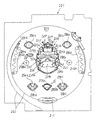
次に、パチンコ遊技機1の裏面の構造について図3を参照して説明する。図3は、遊技機を裏面から見た背面図である。
Next, the structure of the back surface of the
図3に示すように、遊技機裏面側では、可変表示装置9を制御する図柄制御基板80を含む可変表示制御ユニット49、遊技制御用マイクロコンピュータ等が搭載された遊技制御基板(主基板)31が設置されている。また、球払出制御を行う払出制御用マイクロコンピュータ等が搭載された払出制御基板37が設置されている。さらに、遊技盤6に設けられている各種装飾LED、始動記憶表示器18および普通図柄始動記憶表示器41、装飾ランプ25、枠側に設けられている天枠ランプ28a、左枠ランプ28b、右枠ランプ28c、賞球ランプ51および球切れランプ52を点灯制御するランプ制御手段が搭載されたランプ制御基板35、スピーカ27からの音発生を制御する音制御手段が搭載された音制御基板70も設けられている。また、また、DC30V、DC21V、DC12VおよびDC5Vを作成する電源回路が搭載された電源基板910や発射制御基板91が設けられている。
As shown in FIG. 3, on the back side of the gaming machine, a game control board (main board) 31 on which a variable
遊技機裏面において、上方には、各種情報を遊技機外部に出力するための各端子を備えたターミナル基板160が設置されている。ターミナル基板160には、少なくとも、球切れ検出スイッチの出力を導入して外部出力するための球切れ用端子、賞球個数信号を外部出力するための賞球用端子および球貸し個数信号を外部出力するための球貸し用端子が設けられている。また、中央付近には、主基板31からの各種情報を遊技機外部に出力するための各端子を備えた情報端子盤34が設置されている。
On the back side of the gaming machine, a
さらに、各基板(主基板31や払出制御基板37等)に含まれる記憶内容保持手段(例えば、電力供給停止時にもその内容を保持可能な変動データ記憶手段すなわちバックアップRAM)に記憶されたバックアップデータをクリアするための操作手段としてのクリアスイッチ921が搭載されたスイッチ基板190が設けられている。スイッチ基板190には、クリアスイッチ921と、主基板31等の他の基板と接続されるコネクタ922が設けられている。
Further, backup data stored in storage content holding means (for example, variable data storage means that can hold the contents even when power supply is stopped, that is, a backup RAM) included in each board (
貯留タンク38に貯留された遊技球は誘導レールを通り、賞球ケース40Aで覆われた球払出装置に至る。球払出装置の上部には、遊技媒体切れ検出手段としての球切れスイッチ187が設けられている。球切れスイッチ187が球切れを検出すると、球払出装置の払出動作が停止する。球切れスイッチ187は遊技球通路内の遊技球の有無を検出するスイッチであるが、貯留タンク38内の補給球の不足を検出する球切れ検出スイッチ167も誘導レールにおける上流部分(貯留タンク38に近接する部分)に設けられている。球切れ検出スイッチ167が遊技球の不足を検知すると、遊技機設置島に設けられている補給機構から遊技機に対して遊技球の補給が行われる。
The game balls stored in the
入賞にもとづく景品としての遊技球や球貸し要求にもとづく遊技球が多数払い出されて打球供給皿3が満杯になり、さらに遊技球が払い出されると、遊技球は余剰球受皿4に導かれる。さらに遊技球が払い出されると、満タンスイッチ48(図3において図示せず)がオンする。その状態では、球払出装置内の払出モータの回転が停止して球払出装置の動作が停止するとともに発射装置の駆動も停止する。
A large number of game balls as prizes based on winning prizes and game balls based on ball lending requests are paid out to fill the hitting
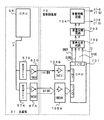
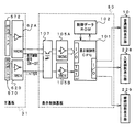
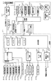
図4は、主基板31における回路構成の一例を示すブロック図である。なお、図4には、払出制御基板37、ランプ制御基板35、音制御基板70、発射制御基板91および図柄制御基板80も示されている。主基板31には、プログラムに従ってパチンコ遊技機1を制御する基本回路53と、ゲートスイッチ32a、始動口スイッチ14a、V入賞スイッチ22、カウントスイッチ23、入賞口スイッチ29a,30a,33a,39a、満タンスイッチ48、球切れスイッチ187、賞球カウントスイッチ301Aおよびクリアスイッチ921からの信号を基本回路53に与えるスイッチ回路58と、可変入賞球装置15を開閉するソレノイド16、開閉板20を開閉するソレノイド21および大入賞口内の経路を切り換えるためのソレノイド21Aを基本回路53からの指令に従って駆動するソレノイド回路59とが搭載されている。
FIG. 4 is a block diagram illustrating an example of a circuit configuration in the
なお、図4には示されていないが、カウントスイッチ短絡信号もスイッチ回路58を介して基本回路53に伝達される。また、ゲートスイッチ32a、始動口スイッチ14a、V入賞スイッチ22、カウントスイッチ23、入賞口スイッチ29a,30a,33a,39a、満タンスイッチ48、球切れスイッチ187、賞球カウントスイッチ301A等のスイッチは、センサと称されているものでもよい。すなわち、遊技球を検出できる遊技媒体検出手段(この例では遊技球検出手段)であれば、その名称を問わない。スイッチと称されているものがセンサと称されているもの等でもよいこと、すなわち、スイッチが遊技媒体検出手段の一例であることは、他の実施の形態でも同様である。
Although not shown in FIG. 4, the count switch short circuit signal is also transmitted to the
また、基本回路53から与えられるデータに従って、大当りの発生を示す大当り情報、可変表示装置9における図柄の可変表示開始に利用された始動入賞球の個数を示す有効始動情報、確率変動が生じたことを示す確変情報等の情報出力信号をホールコンピュータ等の外部装置に対して出力する情報出力回路64が搭載されている。
Further, according to the data given from the
基本回路53は、ゲーム制御用のプログラム等を記憶するROM54、ワークメモリとして使用される記憶手段(変動データを記憶する手段)としてのRAM55、プログラムに従って制御動作を行うCPU56およびI/Oポート部57を含む。この実施の形態では、ROM54,RAM55はCPU56に内蔵されている。すなわち、CPU56は、1チップマイクロコンピュータである。なお、1チップマイクロコンピュータは、少なくともRAM55が内蔵されていればよく、ROM54およびI/Oポート部57は外付けであっても内蔵されていてもよい。
The
また、RAM(CPU内蔵RAMであってもよい。)55の一部または全部が、電源基板910において作成されるバックアップ電源よってバックアップされているバックアップRAMである。すなわち、遊技機に対する電力供給が停止しても、所定期間は、RAM55の一部または全部の内容は保存される。
Further, a part or all of the RAM (may be a CPU built-in RAM) 55 is a backup RAM that is backed up by a backup power source created in the
遊技球を打撃して発射する打球発射装置は発射制御基板91上の回路によって制御される駆動モータ94で駆動される。そして、駆動モータ94の駆動力は、操作ノブ5の操作量に従って調整される。すなわち、発射制御基板91上の回路によって、操作ノブ5の操作量に応じた速度で打球が発射されるように制御される。
A ball hitting device for hitting and launching a game ball is driven by a
なお、この実施の形態では、ランプ制御基板35に搭載されているランプ制御手段が、遊技盤に設けられている始動記憶表示器18、普通図柄始動記憶表示器41および装飾ランプ25の表示制御を行うとともに、枠側に設けられている天枠ランプ28a、左枠ランプ28b、右枠ランプ28c、賞球ランプ51および球切れランプ52の表示制御を行う。各ランプはLEDその他の種類の発光体でもよく、この実施の形態および他の実施の形態で用いられているLEDも他の種類の発光体でもよい。すなわち、ランプやLEDは発光体の一例である。また、特別図柄を可変表示する可変表示装置9および普通図柄を可変表示する普通図柄表示器10の表示制御は、図柄制御基板80に搭載されている表示制御手段によって行われる。
In this embodiment, the lamp control means mounted on the
図5は、図柄制御基板80内の回路構成を、可変表示装置9の一実現例であるLCD(液晶表示装置)82、普通図柄表示器10、主基板31の出力ポート(ポート0,2)570,572および出力バッファ回路620,62Aとともに示すブロック図である。出力ポート(出力ポート2)572からは8ビットのデータが出力され、出力ポート570からは1ビットのストローブ信号(INT信号)が出力される。
FIG. 5 shows the circuit configuration in the
表示制御用CPU101は、制御データROM102に格納されたプログラムに従って動作し、主基板31からノイズフィルタ107および入力バッファ回路105Bを介してINT信号が入力されると、入力バッファ回路105Aを介して表示制御コマンドを受信する。入力バッファ回路105A,105Bとして、例えば汎用ICである74HC540,74HC14を使用することができる。なお、表示制御用CPU101がI/Oポートを内蔵していない場合には、入力バッファ回路105A,105Bと表示制御用CPU101との間に、I/Oポートが設けられる。
The
そして、表示制御用CPU101は、受信した表示制御コマンドに従って、LCD82に表示される画面の表示制御を行う。具体的には、表示制御コマンドに応じた指令をVDP103に与える。VDP103は、キャラクタROM86から必要なデータを読み出す。VDP103は、入力したデータに従ってLCD82に表示するための画像データを生成し、R,G,B信号および同期信号をLCD82に出力する。
Then, the
なお、図5には、VDP103をリセットするためのリセット回路83、VDP103に動作クロックを与えるための発振回路85、および使用頻度の高い画像データを格納するキャラクタROM86も示されている。キャラクタROM86に格納される使用頻度の高い画像データとは、例えば、LCD82に表示される人物、動物、または、文字、図形もしくは記号等からなる画像などである。
5 also shows a reset circuit 83 for resetting the VDP 103, an oscillation circuit 85 for supplying an operation clock to the VDP 103, and a
入力バッファ回路105A,105Bは、主基板31から図柄制御基板80へ向かう方向にのみ信号を通過させることができる。従って、図柄制御基板80側から主基板31側に信号が伝わる余地はない。すなわち、入力バッファ回路105A,105Bは、入力ポートともに不可逆性情報入力手段を構成する。図柄制御基板80内の回路に不正改造が加えられても、不正改造によって出力される信号が主基板31側に伝わることはない。
The
高周波信号を遮断するノイズフィルタ107として、例えば3端子コンデンサやフェライトビーズが使用されるが、ノイズフィルタ107の存在によって、表示制御コマンドに基板間でノイズが乗ったとしても、その影響は除去される。また、主基板31のバッファ回路620,62Aの出力側にもノイズフィルタを設けてもよい。
For example, a three-terminal capacitor or a ferrite bead is used as the
図6は、主基板31およびランプ制御基板35における信号送受信部分を示すブロック図である。この実施の形態では、遊技領域7の外側に設けられている天枠ランプ28a、左枠ランプ28b、右枠ランプ28cと、遊技盤に設けられている装飾ランプ25の点灯/消灯と、賞球ランプ51および球切れランプ52の点灯/消灯とを示すランプ制御コマンドが主基板31からランプ制御基板35に出力される。また、始動記憶表示器18および普通図柄始動記憶表示器41の点灯個数を示すランプ制御コマンドも主基板31からランプ制御基板35に出力される。
FIG. 6 is a block diagram showing signal transmission / reception portions in the
図6に示すように、ランプ制御に関するランプ制御コマンドは、基本回路53におけるI/Oポート部57の出力ポート(出力ポート0,3)570,573から出力される。出力ポート(出力ポート3)573は8ビットのデータを出力し、出力ポート570は1ビットのINT信号を出力する。ランプ制御基板35において、主基板31からの制御コマンドは、入力バッファ回路355A,355Bを介してランプ制御用CPU351に入力する。なお、ランプ制御用CPU351がI/Oポートを内蔵していない場合には、入力バッファ回路355A,355Bとランプ制御用CPU351との間に、I/Oポートが設けられる。
As shown in FIG. 6, the lamp control command related to the lamp control is output from the output ports (
ランプ制御基板35において、ランプ制御用CPU351は、各制御コマンドに応じて定義されている天枠ランプ28a、左枠ランプ28b、右枠ランプ28c、装飾ランプ25の点灯/消灯パターンに従って、天枠ランプ28a、左枠ランプ28b、右枠ランプ28c、装飾ランプ25に対して点灯/消灯信号を出力する。点灯/消灯信号は、天枠ランプ28a、左枠ランプ28b、右枠ランプ28c、装飾ランプ25に出力される。なお、点灯/消灯パターンは、ランプ制御用CPU351の内蔵ROMまたは外付けROMに記憶されている。
In the
主基板31において、CPU56は、RAM55の記憶内容に未払出の賞球残数があるときに賞球ランプ51の点灯を指示する制御コマンドを出力し、前述した遊技盤裏面の払出球通路の上流に設置されている球切れスイッチ187(図3参照)が遊技球を検出しなくなると球切れランプ52の点灯を指示する制御コマンドを出力する。ランプ制御基板35において、各制御コマンドは、入力バッファ回路355A,355Bを介してランプ制御用CPU351に入力する。ランプ制御用CPU351は、それらの制御コマンドに応じて、賞球ランプ51および球切れランプ52を点灯/消灯する。なお、点灯/消灯パターンは、ランプ制御用CPU351の内蔵ROMまたは外付けROMに記憶されている。
In the
さらに、ランプ制御用CPU351は、制御コマンドに応じて始動記憶表示器18および普通図柄始動記憶表示器41に対して点灯/消灯信号を出力する。
Further, the lamp control CPU 351 outputs a turn-on / off signal to the
入力バッファ回路355A,355Bとして、例えば、汎用のCMOS−ICである74HC540,74HC14が用いられる。入力バッファ回路355A,355Bは、主基板31からランプ制御基板35へ向かう方向にのみ信号を通過させることができる。従って、ランプ制御基板35側から主基板31側に信号が伝わる余地はない。たとえ、ランプ制御基板35内の回路に不正改造が加えられても、不正改造によって出力される信号がメイン基板31側に伝わることはない。なお、入力バッファ回路355A,355Bの入力側にノイズフィルタを設けてもよい。
As the
また、主基板31において、出力ポート570,573の外側にバッファ回路620,63Aが設けられている。バッファ回路620,63Aとして、例えば、汎用のCMOS−ICである74HC250,74HC14が用いられる。このような構成によれば、外部から主基板31の内部に入力される信号が阻止されるので、ランプ制御基板70から主基板31に信号が与えられる可能性がある信号ラインをさらに確実になくすことができる。なお、バッファ回路620,63Aの出力側にノイズフィルタを設けてもよい。
In the
なお、主基板31の遊技制御手段から送信されるランプ制御コマンドの送出タイミングは、遊技制御手段による各判定用乱数を生成するためのカウンタのカウント値の更新周期と同期する(ともに2ms毎に実行される遊技制御処理で実行されるので)が、各ランプ・LEDの点灯/消灯のタイミングは、ランプ制御用CPU351の処理時間が介在するので、各判定用乱数を生成するためのカウンタのカウント値の更新周期とは同期しない。
Note that the ramp control command transmission timing transmitted from the game control means of the
図7は、主基板31における音制御コマンドの信号送信部分および音制御基板70の構成例を示すブロック図である。この実施の形態では、遊技進行に応じて、遊技領域7の外側に設けられているスピーカ27の音出力を指示するための音制御コマンドが、主基板31から音制御基板70に出力される。
FIG. 7 is a block diagram showing a configuration example of a sound control command signal transmission portion of the
図7に示すように、音制御コマンドは、基本回路53におけるI/Oポート部57の出力ポート(出力ポート0,4)570,574から出力される。出力ポート(出力ポート4)574からは8ビットのデータが出力され、出力ポート570からは1ビットのINT信号が出力される。音制御基板70において、主基板31からの各信号は、入力バッファ回路705A,705Bを介して音制御用CPU701に入力する。なお、音制御用CPU701がI/Oポートを内蔵していない場合には、入力バッファ回路705A,705Bと音制御用CPU701との間に、I/Oポートが設けられる。
As shown in FIG. 7, the sound control command is output from the output ports (
そして、例えばディジタルシグナルプロセッサによる音声合成回路702は、音制御用CPU701の指示に応じた音声や効果音を発生し音量切替回路703に出力する。音量切替回路703は、音制御用CPU701の出力レベルを、設定されている音量に応じたレベルにして音量増幅回路704に出力する。音量増幅回路704は、増幅した音信号をスピーカ27に出力する。
Then, for example, a
入力バッファ回路705A,705Bとして、例えば、汎用のCMOS−ICである74HC540,74HC14が用いられる。入力バッファ回路705A,705Bは、主基板31から音制御基板70へ向かう方向にのみ信号を通過させることができる。よって、音制御基板70側から主基板31側に信号が伝わる余地はない。従って、音制御基板70内の回路に不正改造が加えられても、不正改造によって出力される信号が主基板31側に伝わることはない。なお、入力バッファ回路705A,705Bの入力側にノイズフィルタを設けてもよい。
As the
また、主基板31において、出力ポート570,574の外側にバッファ回路620,67Aが設けられている。バッファ回路620,67Aとして、例えば、汎用のCMOS−ICである74HC250,74HC14が用いられる。このような構成によれば、外部から主基板31の内部に入力される信号が阻止されるので、音制御基板70から主基板31に信号が与えられる可能性がある信号ラインをさらに確実になくすことができる。なお、バッファ回路620,67Aの出力側にノイズフィルタを設けてもよい。
In the
なお、主基板31の遊技制御手段から送信される音制御コマンドの送出タイミングは、遊技制御手段による各判定用乱数を生成するためのカウンタのカウント値の更新周期と同期する(ともに2ms毎に実行される遊技制御処理で実行されるので)が、スピーカ27からの音発生/音停止のタイミングは、音制御用CPU701の処理時間が介在するので、各判定用乱数を生成するためのカウンタのカウント値の更新周期とは同期しない。
Note that the transmission timing of the sound control command transmitted from the game control means of the
図8は、電源基板910の一構成例を示すブロック図である。電源基板910は、主基板31、図柄制御基板80、音制御基板70、ランプ制御基板35および払出制御基板37等の電気部品制御基板と独立して設置され、遊技機内の各電気部品制御基板および機構部品が使用する電圧を生成する。この例では、AC24V、VSL(DC+30V)、DC+21V、DC+12VおよびDC+5Vを生成する。また、バックアップ電源すなわち記憶保持手段となるコンデンサ916は、DC+5Vすなわち各基板上のIC等を駆動する電源のラインから充電される。なお、VSLは、整流回路912において、整流素子でAC24Vを整流昇圧することによって生成される。VSLは、ソレノイド駆動電源となる。
FIG. 8 is a block diagram illustrating a configuration example of the
トランス911は、交流電源からの交流電圧を24Vに変換する。AC24V電圧は、コネクタ915に出力される。また、整流回路912は、AC24Vから+30Vの直流電圧を生成し、DC−DCコンバータ913およびコネクタ915に出力する。DC−DCコンバータ913は、1つまたは複数のコンバータIC922(図8では1つのみを示す。)を有し、VSLにもとづいて+21V、+12Vおよび+5Vを生成してコネクタ915に出力する。コンバータIC922の入力側には、比較的大容量のコンデンサ923が接続されている。従って、外部からの遊技機に対する電力供給が停止したときに、+30V、+12V、+5V等の直流電圧は、比較的緩やかに低下する。コネクタ915は例えば中継基板に接続され、中継基板から各電気部品制御基板および機構部品に必要な電圧の電力が供給される。
The transformer 911 converts AC voltage from the AC power source into 24V. The AC 24V voltage is output to the
ただし、電源基板910に各電気部品制御基板に至る各コネクタを設け、電源基板910から、中継基板を介さずにそれぞれの基板に至る各電圧を供給するようにしてもよい。また、図8には1つのコネクタ915が代表して示されているが、コネクタは、各電気部品制御基板対応に設けられている。
However, each connector reaching each electric component control board may be provided on the
DC−DCコンバータ913からの+5Vラインは分岐してバックアップ+5Vラインを形成する。バックアップ+5Vラインとグラウンドレベルとの間には大容量のコンデンサ916が接続されている。コンデンサ916は、遊技機に対する電力供給が停止したときの電気部品制御基板のバックアップRAM(電源バックアップされているRAMすなわち電力供給停止時にも記憶内容保持状態となりうるバックアップ記憶手段)に対して記憶状態を保持できるように電力を供給するバックアップ電源となる。また、+5Vラインとバックアップ+5Vラインとの間に、逆流防止用のダイオード917が挿入される。なお、この実施の形態では、バックアップ用の+5Vは、主基板31および払出制御基板37に供給される。
The + 5V line from the DC-DC converter 913 branches to form a backup + 5V line. A large-
また、電源基板910には、電源監視回路としての電源監視用IC902が搭載されている。電源監視用IC902は、VSL電圧を導入し、VSL電圧を監視することによって遊技機への電力供給停止の発生を検出する。具体的には、VSL電圧が所定値(この例では+22V)以下になったら、電力供給の停止が生ずるとして電源断信号を出力する。なお、監視対象の電源電圧は、各電気部品制御基板に搭載されている回路素子の電源電圧(この例では+5V)よりも高い電圧であることが好ましい。この例では、交流から直流に変換された直後の電圧であるVSLが用いられている。電源監視用IC902からの電源断信号は、主基板31や払出制御基板37等に供給される。
The
電源監視用IC902が電力供給の停止を検知するための所定値は、通常時の電圧より低いが、各電気部品制御基板上のCPUが暫くの間動作しうる程度の電圧である。また、電源監視用IC902が、CPU等の回路素子を駆動するための電圧(この例では+5V)よりも高く、また、交流から直流に変換された直後の電圧を監視するように構成されているので、CPUが必要とする電圧に対して監視範囲を広げることができる。従って、より精密な監視を行うことができる。さらに、監視電圧としてVSL(+30V)を用いる場合には、遊技機の各種スイッチに供給される電圧が+12Vであることから、電源瞬断時のスイッチオン誤検出の防止も期待できる。すなわち、+30V電源の電圧を監視すると、+30V作成の以降に作られる+12Vが落ち始める以前の段階でそれの低下を検出できる。
The predetermined value for the
+12V電源の電圧が低下するとスイッチ出力がオン状態を呈するようになるが、+12Vより早く低下する+30V電源電圧を監視して電力供給の停止を認識すれば、スイッチ出力がオン状態を呈する前に電力供給回復待ちの状態に入ってスイッチ出力を検出しない状態となることができる。 When the voltage of the + 12V power supply decreases, the switch output becomes on. However, if the power supply voltage is monitored by monitoring the + 30V power supply voltage, which decreases faster than + 12V, and the power supply is stopped, the switch output is turned on. It is possible to enter a supply recovery waiting state and not detect the switch output.
また、電源監視用IC902は、電気部品制御基板とは別個の電源基板910に搭載されているので、電源監視回路から複数の電気部品制御基板に電源断信号を供給することができる。電源断信号を必要とする電気部品制御基板が幾つあっても電源監視手段は1つ設けられていればよいので、各電気部品制御基板における各電気部品制御手段が後述する復旧制御を行っても、遊技機のコストはさほど上昇しない。
Further, since the
なお、図8に示された構成では、電源監視用IC902の検出信号(電源断信号)は、バッファ回路918,919を介してそれぞれの電気部品制御基板(例えば主基板31と払出制御基板37)に伝達されるが、例えば、1つの検出信号を中継基板に伝達し、中継基板から各電気部品制御基板に同じ信号を分配する構成でもよい。また、電源断信号を必要とする基板数に応じたバッファ回路を設けてもよい。さらに、主基板31と払出制御基板37とに出力される電源断信号について、電源断信号を出力することになる電源監視回路の監視電圧を異ならせてもよい。
In the configuration shown in FIG. 8, the detection signal (power cut-off signal) of the
電源基板910の電源監視回路(電源監視手段)からの電源断信号は、主基板31において、CPU56のマスク不能割込端子(XNMI端子)に接続されている。従って、CPU56は、マスク不能割込(NMI)処理によって遊技機への電力供給の停止の発生を確認することができる。
The power-off signal from the power supply monitoring circuit (power supply monitoring means) on the
CPU56等の駆動電源である+5V電源から電力が供給されていない間、RAMの少なくとも一部は、電源基板から供給されるバックアップ電源によってバックアップされ、遊技機に対する電力供給が停止しても内容は保存される。そして、+5V電源が復旧すると、システムリセット回路65からリセット信号が発せられ、CPU56は、通常の動作状態に復帰する。そのとき、必要なデータがバックアップRAMに保存されているので、停電等からの復旧時に停電等の発生時の遊技状態に復旧させることができる。
While power is not supplied from the + 5V power source that is the driving power source of the
次に遊技機の動作について説明する。図9は、主基板31における遊技制御手段(CPU56およびROM,RAM等の周辺回路)が実行するメイン処理を示すフローチャートである。遊技機に対して電源が投入され、リセット端子の入力レベルがハイレベルになると、CPU56は、ステップS1以降のメイン処理を開始する。メイン処理において、CPU56は、まず、必要な初期設定を行う。
Next, the operation of the gaming machine will be described. FIG. 9 is a flowchart showing main processing executed by game control means (
初期設定処理において、CPU56は、まず、割込禁止に設定する(ステップS1)。次に、割込モードを割込モード2に設定し(ステップS2)、スタックポインタにスタックポインタ指定アドレスを設定する(ステップS3)。そして、内蔵デバイスレジスタの初期化を行う(ステップS4)。また、内蔵デバイス(内蔵周辺回路)であるCTC(カウンタ/タイマ)およびPIO(パラレル入出力ポート)の初期化(ステップS5)を行った後、RAMをアクセス可能状態に設定する(ステップS6)。
In the initial setting process, the
この実施の形態で用いられるCPU56は、I/Oポート(PIO)およびタイマ/カウンタ回路(CTC)も内蔵している。
The
この実施の形態で用いられているCPU56には、マスク可能な割込のモードとして3種類のモードが用意されている。なお、マスク可能な割込が発生すると、CPU56は、自動的に割込禁止状態に設定するとともに、プログラムカウンタの内容をスタックにセーブする。
In the
3種類のうちの割込モード2は、CPU56の特定レジスタ(Iレジスタ)の値(1バイト)と内蔵デバイスが出力する割込ベクタ(1バイト:最下位ビット0)から合成されるアドレスが、割込番地を示すモードである。すなわち、割込番地は、上位アドレスが特定レジスタの値とされ下位アドレスが割込ベクタとされた2バイトで示されるアドレスである。従って、任意の(飛び飛びではあるが)偶数番地に割込処理を設置することができる。各内蔵デバイスは割込要求を行うときに割込ベクタを送出する機能を有している。初期設定処理のステップS2において、CPU56は割込モード2に設定される。
Of the three types of interrupt
次いで、CPU56は、入力ポート1を介して入力されるクリアスイッチ921の出力信号の状態を1回だけ確認する(ステップS7)。その確認においてオンを検出した場合には、CPU56は、通常の初期化処理を実行する(ステップS11〜ステップS15)。クリアスイッチ921がオンである場合(押下されている場合)には、ローレベルのクリアスイッチ信号が出力されている。
Next, the
クリアスイッチ921がオンの状態でない場合には、遊技機への電力供給が停止したときにバックアップRAM領域のデータ保護処理(例えばパリティデータの付加等の電力供給停止時処理)が行われたか否か確認する(ステップS8)。この実施の形態では、電力供給の停止が生じた場合には、バックアップRAM領域のデータを保護するための処理が行われている。そのような保護処理が行われていた場合をバックアップありとする。そのような保護処理が行われていないことを確認したら、CPU56は初期化処理を実行する。
If the
この実施の形態では、バックアップRAM領域にバックアップデータがあるか否かは、電力供給停止時処理においてバックアップRAM領域に設定されるバックアップフラグの状態によって確認される。この例では、例えば、バックアップフラグ領域に「55H」が設定されていればバックアップあり(オン状態)を意味し、「55H」以外の値が設定されていればバックアップなし(オフ状態)を意味する。 In this embodiment, whether or not there is backup data in the backup RAM area is confirmed by the state of the backup flag set in the backup RAM area in the power supply stop process. In this example, for example, if “55H” is set in the backup flag area, it means that there is a backup (ON state), and if a value other than “55H” is set, it means that there is no backup (OFF state). .
バックアップありを確認したら、CPU56は、バックアップRAM領域のデータチェック(この例ではパリティチェック)を行う(ステップS9)。遊技機への電力供給が停止する際に実行される電力供給停止時処理において、チェックサムが算出され、チェックサムはバックアップRAM領域に保存されている。ステップS9では、算出したチェックサムと保存されているチェックサムとを比較する。不測の停電等の電力供給停止が生じた後に復旧した場合には、バックアップRAM領域のデータは保存されているはずであるから、チェック結果(比較結果)は正常(一致)になる。チェック結果が正常でないということは、バックアップRAM領域のデータが、電力供給停止時のデータとは異なっていることを意味する。そのような場合には、内部状態を電力供給停止時の状態に戻すことができないので、電力供給の停止からの復旧時でない電源投入時に実行される初期化処理を実行する。
After confirming that there is a backup, the
チェック結果が正常であれば、CPU56は、遊技制御手段の内部状態と表示制御手段等の電気部品制御手段の制御状態を電力供給停止時の状態に戻すための遊技状態復旧処理を行う(ステップS10)。そして、バックアップRAM領域に保存されていたPC(プログラムカウンタ)の退避値がPCに設定され、そのアドレスに復帰する。遊技状態復旧処理においてPCが電力供給停止時前の状態に復元され、かつ、各種データ(例えば各乱数を生成するためのカウンタ)がバックアップRAMに保存されていることから、遊技機への電力供給が停止した後所定時間(バックアップRAMのデータ保持可能期間)内に電力供給が復旧すれば、例えば、後述する判定用乱数、表示用乱数および初期値用乱数を生成するためのカウンタのカウント値は、電力供給停止時前の状態から継続されることになる。
If the check result is normal, the
初期化処理では、CPU56は、まず、RAMクリア処理を行う(ステップS11)。また、所定の作業領域(例えば、普通図柄判定用乱数カウンタ、普通図柄判定用バッファ、特別図柄左中右図柄バッファ、特別図柄プロセスフラグ、払出コマンド格納ポインタ、賞球中フラグ、球切れフラグ、払出停止フラグなど制御状態に応じて選択的に処理を行うためのフラグ)に初期値を設定する作業領域設定処理を行う(ステップS12)。さらに、球払出装置97からの払出が可能であることを指示する払出許可状態指定コマンドを払出制御基板37に対して送信する処理を行う(ステップS13)。また、他のサブ基板(ランプ制御基板35、音制御基板70、図柄制御基板80)を初期化するための初期化コマンドを各サブ基板に送信する処理を実行する(ステップS14)。初期化コマンドとして、可変表示装置9に表示される初期図柄を示すコマンド(図柄制御基板80に対して)や賞球ランプ51および球切れランプ52の消灯を指示するコマンド(ランプ制御基板35に対して)等がある。
In the initialization process, the
そして、2ms毎に定期的にタイマ割込がかかるようにCPU56に設けられているCTCのレジスタの設定が行われる(ステップS15)。すなわち、初期値として2msに相当する値が所定のレジスタ(時間定数レジスタ)に設定される。
Then, a CTC register set in the
初期化処理の実行(ステップS11〜S15)が完了すると、メイン処理で、表示用乱数更新処理(ステップS17)および初期値用乱数更新処理(ステップS18)が繰り返し実行される。表示用乱数更新処理および初期値用乱数更新処理が実行されるときには割込禁止状態とされ(ステップS16)、表示用乱数更新処理および初期値用乱数更新処理の実行が終了すると割込許可状態とされる(ステップS19)。表示用乱数更新処理および初期値用乱数更新処理が実行されるときには割込禁止状態になっているので、それらの乱数更新処理が実行されている最中に後述する2msタイマ割込が生じ割込処理で乱数更新処理が実行され、カウント値に矛盾が生じてしまうことが防止される。 When the execution of the initialization process (steps S11 to S15) is completed, the display random number update process (step S17) and the initial value random number update process (step S18) are repeatedly executed in the main process. When the display random number update process and the initial value random number update process are executed, the interrupt disabled state is set (step S16). When the display random number update process and the initial value random number update process are finished, the interrupt enabled state is set. (Step S19). When the display random number update process and the initial value random number update process are executed, the interrupt is prohibited. Therefore, a 2 ms timer interrupt described later is generated while the random number update process is being executed. A random number update process is executed in the process, and a contradiction in the count value is prevented.
表示用乱数とは、可変表示装置9に表示される図柄等を決定するための乱数であり、表示用乱数更新処理とは、表示用乱数を発生するためのカウンタのカウント値を更新する処理である。また、初期値用乱数更新処理とは、初期値用乱数を発生するためのカウンタのカウント値を更新する処理である。初期値用乱数とは、大当りとするか否かを決定するための乱数を発生するためのカウンタ(大当り判定用乱数発生カウンタ)等のカウント値の初期値(最大値を越えて値が戻された後の値)を決定するための乱数である。
The display random number is a random number for determining a symbol or the like displayed on the
タイマ割込が発生すると、CPU56は、レジスタの退避処理(ステップS20)を行った後、図10に示すステップS21〜S32の遊技制御処理を実行する。遊技制御処理において、CPU56は、まず、スイッチ回路58を介して、ゲートスイッチ32a、始動口スイッチ14a、カウントスイッチ23および入賞口スイッチ29a,30a,33a,39a等のスイッチの検出信号を入力し、それらの状態判定を行う(スイッチ処理:ステップS21)。
When the timer interrupt occurs, the
次いで、パチンコ遊技機1の内部に備えられている自己診断機能によって種々の異常診断処理が行われ、その結果に応じて必要ならば警報が発せられる(エラー処理:ステップS22)。
Next, various abnormality diagnosis processes are performed by the self-diagnosis function provided in the
次に、遊技制御に用いられる大当り判定用の乱数等の各判定用乱数を生成するための各カウンタのカウント値を更新する処理を行う(ステップS23)。CPU56は、さらに、表示用乱数および初期値用乱数を生成するためのカウンタのカウント値を更新する処理を行う(ステップS24,S25)。
Next, a process of updating the count value of each counter for generating each determination random number such as a big hit determination random number used for game control is performed (step S23). The
さらに、CPU56は、特別図柄プロセス処理を行う(ステップS26)。特別図柄プロセス制御では、遊技状態に応じてパチンコ遊技機1を所定の順序で制御するための特別図柄プロセスフラグに従って該当する処理が選び出されて実行される。そして、特別図柄プロセスフラグの値は、遊技状態に応じて各処理中に更新される。また、普通図柄プロセス処理を行う(ステップS27)。普通図柄プロセス処理では、普通図柄表示器10の表示状態を所定の順序で制御するための普通図柄プロセスフラグに従って該当する処理が選び出されて実行される。そして、普通図柄プロセスフラグの値は、遊技状態に応じて各処理中に更新される。
Further, the
次いで、CPU56は、特別図柄に関する表示制御コマンドをRAM55の所定の領域に設定して表示制御コマンドを送信する処理を行う(特別図柄コマンド制御処理:ステップS28)。また、普通図柄に関する表示制御コマンドをRAM55の所定の領域に設定して表示制御コマンドを送信する処理を行う(普通図柄コマンド制御処理:ステップS29)。
Next, the
さらに、CPU56は、例えばホールコンピュータに供給される大当り情報、始動情報、確率変動情報などのデータを出力する情報出力処理を行う(ステップS30)。
Further, the
また、CPU56は、所定の条件が成立したときにソレノイド回路59に駆動指令を行う(ステップS31)。可変入賞球装置15または開閉板20を開状態または閉状態としたり、大入賞口内の遊技球通路を切り替えたりするために、ソレノイド回路59は、駆動指令に応じてソレノイド16,21,21Aを駆動する。
Further, the
そして、CPU56は、入賞口スイッチ29a,30a,33a,39aの検出信号にもとづく賞球個数の設定などを行う賞球処理を実行する(ステップS32)。具体的には、入賞口スイッチ29a,30a,33a,39aがオンしたことにもとづく入賞検出に応じて、払出制御基板37に賞球個数を示す払出制御コマンドを出力する。払出制御基板37に搭載されている払出制御用CPU371は、賞球個数を示す払出制御コマンドに応じて球払出装置97を駆動する。その後、レジスタの内容を復帰させ(ステップS33)、割込許可状態に設定する(ステップS34)。
Then, the
以上の制御によって、この実施の形態では、遊技制御処理は2ms毎に起動されることになる。なお、この実施の形態では、タイマ割込処理で遊技制御処理が実行されているが、タイマ割込処理では例えば割込が発生したことを示すフラグのセットのみがなされ、遊技制御処理はメイン処理において実行されるようにしてもよい。 With the above control, in this embodiment, the game control process is started every 2 ms. In this embodiment, the game control process is executed by the timer interrupt process. However, in the timer interrupt process, for example, only a flag indicating that an interrupt has occurred is set, and the game control process is performed by the main process. May be executed.
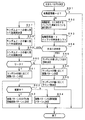
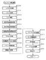
図11は、CPU56が実行する特別図柄プロセス処理のプログラムの一例を示すフローチャートである。図11に示す特別図柄プロセス処理は、図10のフローチャートにおけるステップS26の具体的な処理である。CPU56は、特別図柄プロセス処理を行う際に、変動短縮タイマ減算処理(ステップS310)および始動口スイッチ通過確認処理(ステップS311)を行った後に、内部状態(この例では特別図柄プロセスフラグ)に応じて、ステップS300〜S309のうちのいずれかの処理を行う。
FIG. 11 is a flowchart showing an example of a special symbol process processing program executed by the
変動短縮タイマ減算処理は、始動記憶(始動口スイッチ14aがオンしたことの記憶)の記憶可能最大数に対応した個数設けられている変動短縮タイマを減算する処理である。そして、後述する特別図柄大当り判定処理(ステップS301)において、例えば、変動短縮タイマの値が0になっていて、かつ、低確率状態(通常状態)では始動記憶数が始動記憶の最大値、確変状態では始動記憶数が「2」以上であれば、図柄の変動パターンとして変動時間が短縮されたパターンを用いることに決定される。また、始動口スイッチ通過確認処理は、始動口スイッチ14aがオンしたときに所定の各乱数値を取得して記憶する処理である。
The variation shortening timer subtraction process is a process of subtracting the number of variation shortening timers corresponding to the maximum number that can be stored in the start memory (the memory that the
ステップS300〜S309において、以下のような処理が行われる。 In steps S300 to S309, the following processing is performed.
特別図柄通常処理(ステップS300):始動記憶数を確認し、始動記憶数が0でなければ、ステップS301に移行するように特別図柄プロセスフラグの値を変更する。 Special symbol normal processing (step S300): The starting memory number is confirmed. If the starting memory number is not 0, the value of the special symbol process flag is changed so as to proceed to step S301.
特別図柄大当り判定処理(ステップS301):始動入賞があったときに記憶された各種乱数を格納するバッファ等の内容をシフトする。シフトの結果、押し出されたバッファの内容にもとづいて大当りとするか否かを決定する。具体的には、バッファの内容の一つである大当り判定用乱数の値が所定の値(大当り判定値)と一致した場合に大当りとすることに決定する。なお、バッファは、始動入賞の記憶可能最大数だけ用意されている。また、シフトによって押し出されたバッファの内容は、最も前に生じた始動入賞に応じた内容である。そして、大当りとすることに決定した場合には、大当りフラグをセットする。さらに、バッファの内容の一つであるラウンド数用乱数の値にもとづいて大当り遊技におけるラウンド数を決定する。その後、ステップS302に移行するように特別図柄プロセスフラグの値を変更する。 Special symbol jackpot determination process (step S301): The contents of a buffer or the like for storing various random numbers stored when a start win is received are shifted. As a result of the shift, it is determined whether or not to make a big hit based on the contents of the pushed-out buffer. Specifically, when the value of the random number for jackpot determination, which is one of the contents of the buffer, matches a predetermined value (the jackpot determination value), it is determined to be a jackpot. Note that the maximum number of buffers that can be stored for start winnings is prepared. Further, the content of the buffer pushed out by the shift is the content corresponding to the start winning that occurred most recently. If it is decided to win, the big hit flag is set. Further, the number of rounds in the jackpot game is determined based on the value of the round number random number which is one of the contents of the buffer. Thereafter, the value of the special symbol process flag is changed so as to proceed to step S302.
停止図柄設定処理(ステップS302):可変表示装置9における表示結果である左右中図柄の停止図柄を決定する。そして、ステップS303に移行するように特別図柄プロセスフラグの値を変更する。
Stop symbol setting process (step S302): The stop symbol of the left / right middle symbol which is the display result on the
変動パターン設定処理(ステップS303):可変表示装置9における図柄の変動表示のパターンすなわち変動パターン(可変表示パターン)を決定する。そして、決定された変動パターンおよび停止図柄等を通知するための制御コマンドを図柄制御基板80等に対して出力する。その後、ステップS304に移行するように特別図柄プロセスフラグの値を変更する。
Fluctuation pattern setting process (step S303): A pattern variation display pattern on the
特別図柄変動処理(ステップS304):変動パターンに応じて決められている変動時間が経過したか否か確認する。経過していれば、ステップS305に移行するように特別図柄プロセスフラグの値を変更する。 Special symbol variation processing (step S304): It is confirmed whether or not the variation time determined according to the variation pattern has elapsed. If it has elapsed, the value of the special symbol process flag is changed so as to proceed to step S305.
特別図柄図柄停止処理(ステップS305):図柄制御基板80に対して、特別図柄の停止を指示する表示制御コマンドを送出する制御を行う。また、図柄制御基板80に搭載されている表示制御手段に対して、可変表示装置9を用いてラウンド数を報知させるための表示制御コマンドを送出する制御を行う。その後、大当りとすることに決定されている場合には、ステップS306に移行するように特別図柄プロセスフラグの値を変更する。そうでなければ、ステップS300に移行するように特別図柄プロセスフラグの値を変更する。
Special symbol stop process (step S305): Control is performed to send a display control command to stop the special symbol to the
大入賞口開放前処理(ステップS306):大入賞口を開放する制御を開始する。具体的には、カウンタやフラグを初期化するとともに、ソレノイド54を駆動して大入賞口を開放する。そして、ステップS307に移行するように特別図柄プロセスフラグの値を変更する。
Preliminary winning opening opening process (step S306): Control for opening the large winning opening is started. Specifically, the counter and flag are initialized, and the
大入賞口開放中処理(ステップS307):大入賞口の閉成条件の成立を確認する処理等を行う。大入賞口の閉成条件が成立したら、ステップS308に移行するように特別図柄プロセスフラグの値を変更する。 Processing for opening a special winning opening (step S307): A process for confirming the closing condition of the special winning opening is performed. If the closing condition for the big prize opening is satisfied, the value of the special symbol process flag is changed so as to proceed to step S308.
特定領域有効時間処理(ステップS308):V入賞スイッチ22の通過の有無を監視して、大当り遊技状態継続条件の成立を確認する処理を行う。大当り遊技状態継続の条件が成立し、かつ、まだ残りラウンドがある場合には、ステップS307に移行するように特別図柄プロセスフラグの値を変更する。また、所定の有効時間内に大当り遊技状態継続条件が成立しなかった場合、または、全てのラウンドを終えた場合には、ステップS309に移行するように特別図柄プロセスフラグの値を変更する。
Specific area valid time process (step S308): The presence / absence of passing of the
大当り終了処理(ステップS309):大当り遊技状態が終了したことを遊技者に報知するための表示をランプ制御手段等に行わせる制御を行う。そして、ステップS300に移行するように特別図柄プロセスフラグの値を変更する。 Big hit end processing (step S309): Control is performed to cause the lamp control means or the like to display to notify the player that the big hit gaming state has ended. Then, the value of the special symbol process flag is changed so as to proceed to step S300.
図12は、始動口スイッチ通過確認処理(ステップS311)を示すフローチャートである。打球が遊技盤に設けられている始動入賞口14に入賞すると、始動口スイッチ14aがオンする。CPU56は、スイッチ回路58を介して始動口スイッチ14aがオンしたことを判定すると(ステップS41)、始動記憶数が上限値(この例では4)に達しているかどうか確認する(ステップS42)。始動記憶数が上限値に達していなければ、始動記憶数を1増やし(ステップS43)、大当り判定用乱数、はずれ図柄決定用乱数、大当り図柄決定用乱数、変動パターン決定用乱数およびラウンド数決定用乱数の値を抽出する。そして、それらを始動記憶数の値に対応した乱数値格納エリアに格納する(ステップS44)。始動記憶数が上限値に達している場合には、始動記憶数を増やす処理を行わない。
FIG. 12 is a flowchart showing the start port switch passage confirmation process (step S311). When the hit ball wins the
なお、始動記憶数を1増やした場合には、ランプ制御基板35に対して、始動記憶表示器18の表示数(点灯しているLED数)を1増やすためのランプ制御コマンドが送信される。
When the start memory number is increased by 1, a lamp control command for increasing the display number of the start memory display 18 (the number of lit LEDs) by 1 is transmitted to the
CPU56は、ステップS25の特別図柄プロセス処理において、図13に示すように始動記憶数の値を確認する(ステップS51)。始動記憶数が0でなければ、始動記憶;1(1番目の始動記憶)に対応する乱数値格納エリアに格納されている値を読み出すとともに(ステップS52)、始動記憶数の値を1減らし、かつ、各乱数値格納エリアの値をシフトする(ステップS53)。すなわち、始動記憶;n(n=2,・・・,4)に対応する乱数値格納エリアに格納されている各値を、始動記憶:n−1に対応する乱数値格納エリアに格納する。なお、そのときの始動記憶数に対応した乱数値格納エリアの内容をクリアする。例えば、始動記憶数が4であった場合には、始動記憶;4に対応した特別図柄乱数値格納エリアの内容をクリアする。
In the special symbol process of step S25, the
なお、始動記憶数を1減らした場合には、ランプ制御基板35に対して、始動記憶表示器18の表示数を1減らすためのランプ制御コマンドが送信される。
When the start memory number is decreased by 1, a lamp control command for reducing the display number of the
そして、CPU56は、ステップS52で読み出した値、すなわち抽出されている大当り判定用乱数(特別図柄判定用乱数)の値にもとづいて当り/はずれを決定する(ステップS54)。ここでは、大当り判定用乱数は0〜316の範囲の値をとることにする。そして、図14に示すように、通常状態では、例えばその値が「3」である場合に「大当り」と決定し、それ以外の値である場合には「はずれ」と決定する。また、高確率状態(確変状態)では、例えばその値が「3」,「7」,「79」,「103」,「107」のいずれかである場合に「大当り」と決定し、それ以外の値である場合には「はずれ」と決定する。
Then, the
図15は、各乱数を示す説明図である。各乱数は、以下のように使用される。
(1)ランダム1:大当りを発生させるか否か決定する(大当り判定用)
(2)ランダム2−1〜2−3:左右中のはずれ図柄決定用(特別図柄左右中)
(3)ランダム3:大当りを発生させる特別図柄の組合せを決定する(大当り図柄決定用)
(4)ランダム4:可変表示装置9における特別図柄の変動パターンを決定する(変動パターン決定用)
(5)ランダム5:普通図柄表示器10における普通図柄にもとづく当りを発生させるか否か決定する(普通図柄当り判定用)
(6)ランダム6:大当り遊技におけるラウンド数を決定する(ラウンド数決定用)
(7)ランダム7:ランダム1の初期値を決定する(ランダム1初期値決定用)
(8)ランダム8:ランダム5の初期値を決定する(ランダム5初期値決定用)
(9)ランダム9:ランダム6の初期値を決定する(ランダム6初期値決定用)
FIG. 15 is an explanatory diagram showing each random number. Each random number is used as follows.
(1) Random 1: Decide whether or not to generate a big hit (for big hit judgment)
(2) Random 2-1-2-3: For left and right middle detachment symbol determination (special symbol left and right middle)
(3) Random 3: Determines the combination of special symbols that generate a big hit (for determining big hit symbols)
(4) Random 4: Determines the variation pattern of the special symbol in the variable display device 9 (for variation pattern determination)
(5) Random 5: Decide whether or not to generate a hit based on the normal symbol in the normal symbol display 10 (for normal symbol per unit determination)
(6) Random 6: Determine the number of rounds in the jackpot game (for round number determination)
(7) Random 7: Determine initial value of random 1 (for determining random 1 initial value)
(8) Random 8: Determine initial value of random 5 (for determining random 5 initial value)
(9) Random 9: Determine initial value of random 6 (for determining random 6 initial value)
なお、図10に示された遊技制御処理におけるステップS23では、CPU56は、(1)の大当り判定用乱数、(3)の大当り図柄決定用乱数、(5)の普通図柄当り判定用乱数および(6)のラウンド数決定用乱数を生成するためのカウンタのカウントアップ(1加算)を行う。すなわち、それらが判定用乱数であり、それら以外の乱数が表示用乱数または初期値用乱数である。なお、遊技効果を高めるために、上記(1)〜(9)の乱数以外の普通図柄に関する乱数等も用いられている。また、図15に示された各乱数値のとりうる範囲も一例であって、他の範囲を用いることもできる。
In step S23 in the game control process shown in FIG. 10, the
図13に示すステップS54において、大当りと判定されたときには、大当り図柄用乱数(ランダム3)の値に従って大当り図柄を決定する(ステップS55)。例えば、ランダム3の値に応じた大当り図柄テーブルに設定されている図柄番号の各図柄が、大当り図柄として決定される。大当り図柄テーブルには、複数種類の大当り図柄の組み合わせのそれぞれに対応した左右中の図柄番号が設定されている。また、変動パターン決定用乱数(ランダム4)を抽出し、ランダム4の値にもとづいて図柄の変動パターンを決定する(ステップS56)。さらに、ラウンド数決定用乱数(ランダム6)を抽出し、ランダム6の値にもとづいてラウンド数を決定する(ステップS65)。 In step S54 shown in FIG. 13, when it is determined that the jackpot is a jackpot symbol according to the value of the jackpot symbol random number (random 3) (step S55). For example, each symbol of the symbol number set in the jackpot symbol table corresponding to the value of random 3 is determined as a jackpot symbol. In the jackpot symbol table, left and right middle symbol numbers corresponding to combinations of a plurality of types of jackpot symbols are set. Further, a random number for determining a variation pattern (random 4) is extracted, and a variation pattern of the symbol is determined based on the random 4 value (step S56). Further, a random number for determining the number of rounds (random 6) is extracted, and the number of rounds is determined based on the value of random 6 (step S65).
はずれと判定された場合には、CPU56は、大当りとしない場合の停止図柄の決定を行う。この実施の形態では、ステップS52で読み出した値、すなわち抽出されているランダム2−1の値に従って左図柄を決定する(ステップS57)。また、ランダム2−2の値に従って中図柄を決定する(ステップS58)。そして、ランダム2−3の値に従って右図柄を決定する(ステップS59)。ここで、決定された中図柄が左右図柄と一致した場合には、中図柄に対応した乱数の値に1加算した値に対応する図柄を中図柄の停止図柄として、大当り図柄と一致しないようにする。
When it is determined that there is a loss, the
さらに、CPU56は、リーチすることに決定されたか否か(左右の停止図柄が揃っているか否か)を確認し(ステップS60)、リーチすることに決定されている場合には、変動パターン決定用乱数(ランダム4)の値を抽出し、ランダム4にもとづいて図柄の変動パターンを決定する(ステップS61)。
Further, the
リーチすることに決定されていない場合には、確変状態か否かを確認する(ステップS62)。確変状態であれば変動パターンをはずれ時短縮変動パターンとすることに決定する(ステップS63)。確変状態でなければ変動パターンをはずれ時の通常変動パターンとすることに決定する(ステップS64)。なお、はずれ時短縮変動パターンは、左右中の図柄の変動時間が例えば4.0秒という通常変動パターンよりも変動期間が短い変動パターンである。 If it is not decided to reach, it is confirmed whether or not it is in the probability variation state (step S62). If it is in the probability variation state, the variation pattern is determined to be the off-time variation variation pattern (step S63). If it is not the probability variation state, it is determined that the variation pattern is the normal variation pattern at the time of deviation (step S64). In addition, the fluctuation pattern shortened at the time of detachment is a fluctuation pattern in which the fluctuation period is shorter than the normal fluctuation pattern in which the fluctuation time of the left and right symbols is, for example, 4.0 seconds.
以上のようにして、始動入賞にもとづく図柄の変動態様を、リーチ態様とするか、はずれ態様とするか決定され、それぞれの停止図柄の組合せが決定される。すなわち、図柄の変動態様として、リーチ演出を行うのか行わないのかが決定されるとともに停止図柄の組合せが決定される。また、大当りとすることに決定された場合には、大当り遊技におけるラウンド数も決定される。 As described above, it is determined whether the pattern variation mode based on the start winning is the reach mode or the off mode, and the combination of the respective stop symbols is determined. That is, as a symbol variation mode, whether or not a reach effect is performed is determined and a combination of stop symbols is determined. In addition, when it is determined to be a big hit, the number of rounds in the big hit game is also determined.
なお、図13に示された処理は、図11に示された特別図柄プロセス処理におけるステップS301〜S303の処理をまとめて示した場合の処理に相当する。また、この実施の形態では、左右中図柄の停止図柄が揃った場合に大当りが発生する。左右図柄のみが揃った場合にリーチとなる。 The process shown in FIG. 13 corresponds to the process in the case where the processes of steps S301 to S303 in the special symbol process shown in FIG. 11 are collectively shown. In this embodiment, a big hit occurs when the left and right middle symbols are aligned. Reach when only left and right symbols are available.
図16および図17は、図10に示された遊技制御処理で実行される判定用乱数更新処理(ステップS23)の一例を示すフローチャートである。判定用乱数更新処理において、CPU56は、ランダム1(大当り判定用乱数)を生成するためのカウンタの値を+1する(ステップS101)。そして、ランダム1を生成するためのカウンタの値が(最大値+1)以上になっている場合には(ステップS102)、カウント値を0に戻す(ステップS103)。なお、この実施の形態では、(最大値+1)は317である。また、所定のタイミングでランダム1を生成するためのカウンタ(ランダム1用カウンタ)から読み出された値が、抽出されたランダム1(大当り判定用乱数)である。同様に、他のランダム2等を生成するためのカウンタから読み出された値が、抽出されたランダム2等である。以下、ランダムn(n:1,2,・・・)を生成するためのカウンタをランダムn用カウンタということがある。
16 and 17 are flowcharts showing an example of the determination random number update process (step S23) executed in the game control process shown in FIG. In the determination random number update process, the
次いで、CPU56は、ランダム1を生成するためのカウンタの値が初期値としてランダム1用初期値バッファに保存されている値と一致したか否か確認する(ステップS104)。一致していなければ、カウント値はそのままである。一致していた場合には、ランダム7(ランダム1初期値決定用乱数)を抽出する(ステップS105)。すなわち、ランダム7を生成するためのカウンタのカウント値を入力する。そして、抽出された値を初期値としてランダム1用初期値バッファに保存するとともに(ステップS106)、抽出された値を、ランダム1を生成するためのカウンタに設定する(ステップS107)。よって、この時点で、ランダム1を生成するためのカウンタの初期値が変更される。なお、遊技機に電源が投入されたときには一般には初期値として「0」がランダム1を生成するためのカウンタおよびランダム1用初期値バッファに保存されるが、バックアップRAMにランダム1の値が保存されていた場合には電源投入時に保存値に戻される。また、ランダム1用初期値バッファもバックアップRAMに形成される。遊技制御手段は、電力供給が復旧した場合に、変動データ記憶手段に保持されている数値にもとづいて、数値の更新を継続する。
Next, the
次に、ランダム3(大当り図柄決定用乱数)を生成するためのカウンタの値を+1する(ステップS108)。ランダム3を生成するためのカウンタの値が(最大値+1)以上になっている場合には(ステップS109)、カウント値を0に戻す(ステップS110)。なお、この実施の形態では、(最大値+1)は12である。 Next, the value of the counter for generating random 3 (big hit symbol determination random number) is incremented by 1 (step S108). When the value of the counter for generating random 3 is equal to or greater than (maximum value + 1) (step S109), the count value is returned to 0 (step S110). In this embodiment, (maximum value + 1) is 12.
また、ランダム5(普通図柄当り判定用乱数)を生成するためのカウンタの値を+1する(ステップS121)。ランダム5を生成するためのカウンタの値が(最大値+1)以上になっている場合には(ステップS122)、カウント値を3に戻す(ステップS123)。なお、この実施の形態では、(最大値+1)は14である。 Also, the counter value for generating random 5 (normal random number for determination per symbol) is incremented by 1 (step S121). When the value of the counter for generating random 5 is equal to or greater than (maximum value + 1) (step S122), the count value is returned to 3 (step S123). In this embodiment, (maximum value + 1) is 14.
そして、CPU56は、ランダム5を生成するためのカウンタの値が初期値としてランダム5用初期値バッファに保存されている値と一致したか否か確認する(ステップS124)。一致していなければ、カウント値はそのままである。一致していた場合には、ランダム8(ランダム5初期値決定用乱数)を抽出する(ステップS125)。すなわち、ランダム8を生成するためのカウンタのカウント値を入力する。そして、抽出された値を初期値としてランダム5用初期値バッファに保存するとともに(ステップS126)、抽出された値を、ランダム5を生成するためのカウンタに設定する(ステップS127)。よって、この時点で、ランダム5を生成するためのカウンタの初期値が変更される。なお、遊技機に電源が投入されたときに初期値として「3」がランダム5を生成するためのカウンタに設定されるが、バックアップRAMにランダム5の値が保存されていた場合には電源投入時に保存値に戻される。また、ランダム5用初期値バッファもバックアップRAMに形成される。遊技制御手段は、電力供給が復旧した場合に、変動データ記憶手段に保持されている数値にもとづいて、数値の更新を継続する。
Then, the
また、ランダム6(ラウンド数決定用乱数)を生成するためのカウンタの値を+1する(ステップS111)。ランダム6を生成するためのカウンタの値が(最大値+1)以上になっている場合には(ステップS112)、カウント値を0に戻す(ステップS113)。なお、この実施の形態では、(最大値+1)は19である。 Further, the counter value for generating random 6 (round number determination random number) is incremented by 1 (step S111). When the value of the counter for generating random 6 is equal to or greater than (maximum value + 1) (step S112), the count value is returned to 0 (step S113). In this embodiment, (maximum value + 1) is 19.
そして、CPU56は、ランダム6を生成するためのカウンタの値が初期値としてランダム6用初期値バッファに保存されている値と一致したか否か確認する(ステップS114)。一致していなければ、カウント値はそのままである。一致していた場合には、ランダム9(ランダム6初期値決定用乱数)を抽出する(ステップS115)。すなわち、ランダム9を生成するためのカウンタのカウント値を入力する。そして、抽出された値を初期値としてランダム6用初期値バッファに保存するとともに(ステップS116)、抽出された値を、ランダム6を生成するためのカウンタに設定する(ステップS117)。よって、この時点で、ランダム6を生成するためのカウンタの初期値が変更される。なお、遊技機に電源が投入されたときに初期値として「0」がランダム6を生成するためのカウンタに設定されるが、バックアップRAMにランダム6の値が保存されていた場合には電源投入時に保存値に戻される。また、ランダム6用初期値バッファもバックアップRAMに形成される。遊技制御手段は、電力供給が復旧した場合に、変動データ記憶手段に保持されている数値にもとづいて、数値の更新を継続する。
Then, the
図18は、図10に示された遊技制御処理において1回実行されるとともに(ステップS25)、図9に示されたメイン処理における割込余り時間(遊技制御処理終了後、次回の2msタイマ割込が発生するまでの時間)で繰り返し実行される(ステップS18)初期値用乱数更新処理の一例を示すフローチャートである。 FIG. 18 is executed once in the game control process shown in FIG. 10 (step S25), and the remaining surplus time in the main process shown in FIG. It is a flowchart showing an example of an initial value random number update process (step S18) that is repeatedly executed at a time until the occurrence of the error.
初期値用乱数更新処理において、CPU56は、ランダム7(ランダム1初期値決定用乱数)を生成するためのカウンタの値を+1する(ステップS131)。ランダム7を生成するためのカウンタの値が(最大値+1)以上になっている場合には(ステップS132)、カウント値を0に戻す(ステップS133)。なお、(最大値+1)は、ランダム1の場合と同様に317である。
In the initial value random number update process, the
また、ランダム8(ランダム5初期値決定用乱数)を生成するためのカウンタの値を+1する(ステップS134)。ランダム8を生成するためのカウンタの値が(最大値+1)以上になっている場合には(ステップS135)、カウント値を3に戻す(ステップS136)。なお、(最大値+1)は、ランダム5の場合と同様に14である。 Further, the counter value for generating random 8 (random 5 initial value determining random number) is incremented by 1 (step S134). When the value of the counter for generating the random 8 is equal to or greater than (maximum value + 1) (step S135), the count value is returned to 3 (step S136). Note that (maximum value + 1) is 14 as in the case of random 5.
さらに、ランダム9(ランダム6初期値決定用乱数)を生成するためのカウンタの値を+1する(ステップS137)。ランダム9を生成するためのカウンタの値が(最大値+1)以上になっている場合には(ステップS138)、カウント値を0に戻す(ステップS139)。なお、(最大値+1)は、ランダム6の場合と同様に19である。 Further, the counter value for generating random 9 (random 6 initial value determining random number) is incremented by 1 (step S137). If the value of the counter for generating random 9 is equal to or greater than (maximum value + 1) (step S138), the count value is returned to 0 (step S139). Note that (maximum value + 1) is 19 as in the case of random 6.
図19は、図10に示された遊技制御処理において1回実行されるとともに(ステップS24)、図9に示されたメイン処理における割込余り時間で繰り返し実行される(ステップS17)表示用乱数更新処理の一例を示すフローチャートである。 FIG. 19 is executed once in the game control process shown in FIG. 10 (step S24), and is repeatedly executed in the surplus interruption time in the main process shown in FIG. 9 (step S17). It is a flowchart which shows an example of an update process.
表示用乱数更新処理において、CPU56は、ランダム4(変動パターン決定用乱数)を生成するためのカウンタの値を+3する(ステップS151)。ランダム4を生成するためのカウンタの値が251以上になっている場合には(ステップS152)、ランダム4を生成するためのカウンタのカウント値を251減らす(ステップS153)。
In the display random number update process, the
なお、この実施の形態では、ランダム4の最大値は250であるが、ランダム4を生成するためのカウンタのカウント値は3ずつ増えていくので、値が0から始まった場合には、249になった後には252になる。すると、251減らすと、その値は1になる。また、値が1から始まった場合には、250になった後に253になる。すると、251減らすと、その値は2になる。また、値が2から始まった場合には、248になった後に251になる。すると、251減らすと、その値は0になる。すなわち、ランダム4の値の初期値(最大値を越えて値が戻された後の値)も、ある程度ランダムになっている。 In this embodiment, the maximum value of random 4 is 250, but the count value of the counter for generating random 4 is increased by 3. Therefore, when the value starts from 0, it is 249. It becomes 252 after becoming. Then, when 251 is decreased, the value becomes 1. When the value starts from 1, it becomes 253 after it becomes 250. Then, when 251 is reduced, the value becomes 2. When the value starts from 2, it becomes 251 after becoming 248. Then, when 251 is decreased, the value becomes 0. That is, the initial value of the random 4 value (the value after the value is returned beyond the maximum value) is also somewhat random.
次に、ランダム2−1(左のはずれ図柄決定用乱数)を生成するためのカウンタの値を+1する(ステップS154)。ランダム2−1を生成するためのカウンタの値が(最大値+1)以上になっている場合には(ステップS155)、カウント値を0に戻す(ステップS156)。なお、この実施の形態では、(最大値+1)は12である。 Next, +1 is added to the counter value for generating random 2-1 (the left random symbol for random design determination) (step S154). When the value of the counter for generating random 2-1 is equal to or greater than (maximum value + 1) (step S155), the count value is returned to 0 (step S156). In this embodiment, (maximum value + 1) is 12.
ランダム2−1を生成するためのカウンタの値が(最大値+1)以上になって値が0に戻された場合、すなわち桁上げが生じた場合には、ランダム2−2(中のはずれ図柄決定用乱数)を生成するためのカウンタの値を+1する(ステップS157)。ランダム2−2を生成するためのカウンタの値が(最大値+1)以上になっている場合には(ステップS158)、カウント値を0に戻す(ステップS159)。なお、この実施の形態では、(最大値+1)は12である。 When the value of the counter for generating random 2-1 is equal to or greater than (maximum value +1) and the value is returned to 0, that is, when a carry occurs, random 2-2 (middle off symbol) The counter value for generating (decision random number) is incremented by 1 (step S157). When the value of the counter for generating random 2-2 is equal to or greater than (maximum value + 1) (step S158), the count value is returned to 0 (step S159). In this embodiment, (maximum value + 1) is 12.
ランダム2−3を生成するためのカウンタの値が(最大値+1)以上になって値が0に戻された場合、すなわち桁上げが生じた場合には、ランダム2−3(右のはずれ図柄決定用乱数)を生成するためのカウンタの値を+1する(ステップS160)。ランダム2−3を生成するためのカウンタの値が(最大値+1)以上になっている場合には(ステップS161)、カウント値を0に戻す(ステップS162)。なお、この実施の形態では、(最大値+1)は12である。 When the value of the counter for generating random 2-3 becomes (maximum value + 1) or more and the value is returned to 0, that is, when a carry occurs, random 2-3 (the right off-set symbol) The counter value for generating (decision random number) is incremented by 1 (step S160). When the value of the counter for generating random 2-3 is (maximum value + 1) or more (step S161), the count value is returned to 0 (step S162). In this embodiment, (maximum value + 1) is 12.
図20は、図16および図17に示された判定用乱数更新処理によって変化するランダム1(大当り判定用乱数)を生成するためのカウンタの値の一例を示す説明図である。この例では、ランダム1の最初の値は0になっている。また、最初は初期値として「0」が保存されているので、カウント値が「316」まで進み、そこで+1されて値が0に戻ると(ステップS101,S102,S103)、ステップS104の処理でカウント値が初期値と一致したことが検出される。すると、ステップS105の処理でランダム7(ランダム1初期値決定用乱数)が抽出される。なお、この時点は、図20においてAで示されている。 FIG. 20 is an explanatory diagram illustrating an example of a counter value for generating random 1 (a big hit determination random number) that is changed by the determination random number update process illustrated in FIGS. 16 and 17. In this example, the first value of random 1 is 0. Since “0” is initially stored as an initial value, the count value advances to “316”, and when the count value is incremented by 1 and returns to 0 (steps S101, S102, S103), the process of step S104 is performed. It is detected that the count value matches the initial value. Then, random 7 (random 1 initial value determination random number) is extracted in the process of step S105. This time point is indicated by A in FIG.
ここで、その時点のランダム7を生成するためのカウンタのカウント値が「19」であったとする。すると、ランダム7として「19」が抽出され、その値が保存されるとともに(ステップS106)、ランダム1を生成するためのカウンタにその値が設定される。従って、この時点から、ランダム1を生成するためのカウンタは、初期値「19」から歩進することになる。 Here, it is assumed that the count value of the counter for generating the random 7 at that time is “19”. Then, “19” is extracted as random 7 and the value is stored (step S106), and the value is set in the counter for generating random 1. Therefore, from this time point, the counter for generating random 1 advances from the initial value “19”.
ランダム1を生成するためのカウンタの値が歩進して「19」になると、ステップS104の処理でカウント値が初期値と一致したことが検出される。すると、ステップS105の処理でランダム7が抽出される。なお、この時点は、図20においてBで示されている。その時点のランダム7を生成するためのカウンタのカウント値が「195」であったとする。すると、ランダム7として「195」が抽出され、その値が保存されるとともに(ステップS106)、ランダム1を生成するためのカウンタにその値が設定される。従って、この時点から、ランダム1を生成するためのカウンタは、初期値「195」から歩進する。 When the value of the counter for generating random 1 advances to “19”, it is detected in step S104 that the count value matches the initial value. Then, random 7 is extracted by the process of step S105. This time point is indicated by B in FIG. Assume that the count value of the counter for generating random 7 at that time is “195”. Then, “195” is extracted as random 7 and the value is stored (step S106), and the value is set in the counter for generating random 1. Therefore, from this point, the counter for generating random 1 advances from the initial value “195”.
そして、ランダム1を生成するためのカウンタの値が歩進して「195」になると、ステップS104の処理でカウント値が初期値と一致したことが検出される。すると、ステップS105の処理でランダム7が抽出される。なお、この時点は、図20においてCで示されている。その時点のランダム7を生成するためのカウンタのカウント値が「n」であったとする。すると、ランダム7として「n」が抽出され、その値が保存されるとともに(ステップS106)、ランダム1を生成するためのカウンタにその値が設定される。従って、この時点から、ランダム1を生成するためのカウンタは、初期値「n」から歩進する。なお、図20において、星印(☆)は、カウント値が「3(低確率時の大当り判定値)」となる位置を示している。
When the value of the counter for generating random 1 advances to “195”, it is detected in step S104 that the count value matches the initial value. Then, random 7 is extracted by the process of step S105. This time point is indicated by C in FIG. It is assumed that the count value of the counter for generating the random 7 at that time is “n”. Then, “n” is extracted as the
以上のように、ランダム1を生成するためのカウンタの値が1周(317カウント)する度に、カウント値として新たな初期値が設定され、以後、カウンタはその値から歩進していく。ランダム1を生成するためのカウンタ(大当り判定用カウンタ)の初期値を決定するためのカウンタ(ランダム7を生成するためのカウンタ)は、CPU56が実行する遊技制御処理の余り時間(遊技制御処理が終了してから次に2msタイマ割込が発生するまでの時間)でカウントアップされている。そして、その余り時間は、遊技の進行状況に応じて異なるので、ランダムな期間になっている。その結果、生成されるランダム7の値もランダムな値になるので、大当り判定用カウンタの初期値もランダムに変化する。 As described above, every time the value of the counter for generating random 1 makes one round (317 counts), a new initial value is set as the count value, and thereafter the counter advances from that value. A counter (counter for generating random 7) for determining an initial value of a counter for generating random 1 (a jackpot determination counter) is a surplus time of game control processing executed by the CPU 56 (game control processing The time is counted up until the next 2 ms timer interrupt occurs). The extra time varies depending on the progress of the game, and is a random period. As a result, since the generated random 7 value is also a random value, the initial value of the jackpot determination counter also changes randomly.
つまり、大当り判定用カウンタの値が1周する度に、ランダムな初期値からあらためてカウンタの歩進が始まる。すると、不正基板が主基板31に接続され、主基板31から出力される信号にもとづいて大当り判定用カウント値更新タイミングが認識されたとしても、大当り判定用カウント値が大当り判定値になるタイミングをねらって不正な始動入賞信号を主基板31に送り込むことは困難になる。この実施の形態によれば、図20に星印で示されたように、大当り判定用カウント値が大当り判定値になるタイミングに規則性はなくランダムになっているからである。
That is, every time the value of the big hit determination counter makes one round, the counter starts to increment from a random initial value. Then, even if the illegal board is connected to the
この実施の形態では、さらに、ラウンド数決定用乱数の初期値もランダムになるように制御される。図21は、図16および図17に示された判定用乱数更新処理によって変化するランダム6(ラウンド数決定用乱数)を生成するためのカウンタの値の一例を示す説明図である。この例では、ランダム6の最初の値は0になっている。また、最初は初期値として「0」が保存されているので、カウント値が「18」まで進み、そこで+1されて値が0に戻ると(ステップS111,S112,S113)、ステップS114の処理でカウント値が初期値と一致したことが検出される。すると、ステップS115の処理でランダム9(ランダム6初期値決定用乱数)が抽出される。なお、この時点は、図21においてAで示されている。 In this embodiment, the initial value of the round number determination random number is further controlled to be random. FIG. 21 is an explanatory diagram showing an example of a counter value for generating random 6 (round number determination random number) that changes by the determination random number update process shown in FIGS. 16 and 17. In this example, the initial value of random 6 is 0. Since “0” is initially stored as an initial value, the count value advances to “18”, and when the count value is incremented by 1 and returns to 0 (steps S111, S112, S113), the process of step S114 is performed. It is detected that the count value matches the initial value. Then, random 9 (random 6 initial value determination random number) is extracted in the process of step S115. This time point is indicated by A in FIG.
ここで、その時点のランダム6を生成するためのカウンタのカウント値が「3」であったとする。すると、ランダム9として「3」が抽出され、その値が保存されるとともに(ステップS116)、ランダム6を生成するためのカウンタにその値が設定される。従って、この時点から、ランダム6を生成するためのカウンタは、初期値「3」から歩進することになる。
Here, it is assumed that the count value of the counter for generating the random 6 at that time is “3”. Then, “3” is extracted as random 9 and the value is stored (step S116), and the value is set in a counter for generating random 6. Therefore, from this point, the counter for generating the
ランダム6を生成するためのカウンタの値が歩進して「3」になると、ステップS114の処理でカウント値が初期値と一致したことが検出される。すると、ステップS115の処理でランダム9が抽出される。なお、この時点は、図21においてBで示されている。その時点のランダム9を生成するためのカウンタのカウント値が「11」であったとする。すると、ランダム9として「11」が抽出され、その値が保存されるとともに(ステップS116)、ランダム6を生成するためのカウンタにその値が設定される。従って、この時点から、ランダム6を生成するためのカウンタは、初期値「11」から歩進する。 When the value of the counter for generating the random 6 advances to “3”, it is detected in step S114 that the count value matches the initial value. Then, random 9 is extracted by the process of step S115. This time point is indicated by B in FIG. Assume that the count value of the counter for generating the random 9 at that time is “11”. Then, “11” is extracted as random 9, the value is stored (step S116), and the value is set in the counter for generating random 6. Therefore, from this point, the counter for generating random 6 advances from the initial value “11”.
そして、ランダム6を生成するためのカウンタの値が歩進して「11」になると、ステップS114の処理でカウント値が初期値と一致したことが検出される。すると、ステップS115の処理でランダム9が抽出される。なお、この時点は、図21においてCで示されている。その時点のランダム9を生成するためのカウンタのカウント値が「k」であったとする。すると、ランダム9として「k」が抽出され、その値が保存されるとともに(ステップS116)、ランダム6を生成するためのカウンタにその値が設定される。従って、この時点から、ランダム6を生成するためのカウンタは、初期値「k」から歩進する。なお、図21において、星印(☆)は、カウント値が「11(最大ラウンド数に対応した判定値とする)」となる位置を示している。 When the value of the counter for generating the random 6 advances to “11”, it is detected that the count value matches the initial value in the process of step S114. Then, random 9 is extracted by the process of step S115. This time point is indicated by C in FIG. Assume that the count value of the counter for generating random 9 at that time is “k”. Then, “k” is extracted as random 9 and the value is stored (step S116), and the value is set in the counter for generating random 6. Therefore, from this time point, the counter for generating random 6 advances from the initial value “k”. In FIG. 21, an asterisk (☆) indicates a position where the count value is “11 (determined value corresponding to the maximum number of rounds)”.
以上のように、ランダム6を生成するためのカウンタの値が1周(19カウント)する度に、カウント値として新たな初期値が設定され、以後、カウンタはその値から歩進していく。ランダム6を生成するためのカウンタ(ラウンド数決定用カウンタ)の初期値を決定するためのカウンタ(ランダム9を生成するためのカウンタ)は、遊技制御手段におけるCPUが実行する遊技制御処理の余り時間(遊技制御処理が終了してから次に2msタイマ割込が発生するまでの時間)でカウントアップされている。そして、その余り時間は、遊技の進行状況に応じて異なるので、ランダムな期間になっている。その結果、生成されるランダム9の値もランダムな値になるので、ラウンド数決定用カウンタの初期値もランダムに変化する。 As described above, every time the value of the counter for generating random 6 makes one round (19 counts), a new initial value is set as the count value, and thereafter the counter advances from that value. The counter (counter for generating random 9) for determining the initial value of the counter for generating random 6 (round number determining counter) is the surplus time of the game control processing executed by the CPU in the game control means It is counted up (time from the end of the game control process until the next 2 ms timer interrupt is generated). The extra time varies depending on the progress of the game, and is a random period. As a result, since the generated random 9 value also becomes a random value, the initial value of the round number determination counter also changes randomly.
つまり、ラウンド数決定用カウンタの値が1周する度に、ランダムな初期値からあらためてカウンタの歩進が始まる。すると、不正基板が主基板に接続され、主基板から出力される信号にもとづいてラウンド数決定用カウント値更新タイミングが認識されたとしても、ラウンド数決定用カウント値が大きなラウンド数に対応した判定値になるタイミングをねらって不正な信号(始動入賞信号等)を主基板31に送り込むことは困難になる。この実施の形態によれば、図21に星印で示されたように、ラウンド数決定用カウント値が大きなラウンド数に対応した判定値に一致するタイミングに規則性はなくランダムになっているからである。
That is, every time the value of the counter for determining the number of rounds makes one round, the counter starts to increment from the random initial value. Then, even if the illegal board is connected to the main board and the round value determination count value update timing is recognized based on the signal output from the main board, the determination corresponding to the round number with a large round number determination count value It is difficult to send an illegal signal (such as a start winning signal) to the
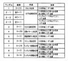
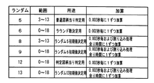
図22は、ラウンド数決定用乱数とラウンド数決定用の判定値との関係の一例を示す説明図である。図22に示す例では、遊技機の状態が低確率状態にあることには、抽出されたラウンド数決定用乱数の値が2,4,6,8,10,12,14,16,18に一致した場合にはラウンド数が12に決定され、ラウンド数決定用乱数の値が1,5,9,13,17に一致した場合にはラウンド数が14に決定され、ラウンド数決定用乱数の値が3,7,11,15に一致した場合にはラウンド数が16に決定される。また、遊技機の状態が高確率状態にあることには、抽出されたラウンド数決定用乱数の値が2,4,6,8,10,12,14,16,18に一致した場合にはラウンド数が14に決定され、ラウンド数決定用乱数の値が1,3,5,7,11,13,15,17に一致した場合にはラウンド数が16に決定される。
FIG. 22 is an explanatory diagram illustrating an example of a relationship between a round number determining random number and a round number determining determination value. In the example shown in FIG. 22, when the state of the gaming machine is in a low probability state, the extracted random number for determining the number of rounds is 2, 4, 6, 8, 10, 12, 14, 16, 18 If they match, the round number is determined to be 12, and if the round number determination random number values match 1, 5, 9, 13, and 17, the round number is determined to be 14, and the round number determination random number When the
図23は、ラウンド数報知の一例を示す説明図である。この例では、可変表示装置9において大当りとなる図柄が表示されたに後、可変表示装置9において、遊技制御手段が決定したラウンド数を示す画面が表示される。
FIG. 23 is an explanatory diagram showing an example of round number notification. In this example, after the symbol that is a big hit is displayed on the
なお、上記の例では大当り遊技中のラウンド数はラウンド数決定用乱数の値にもとづいて決定されたが、特別図柄の停止図柄に応じてラウンド数が決定されるようにしてもよい。図24は、そのようなラウンド数決定方式の一例を示す説明図である。特別図柄の停止図柄に応じてラウンド数が決定される場合には、ラウンド数決定用乱数は使用されず、大当り図柄決定用乱数が、ラウンド数を決定するための乱数を兼ねる。 In the above example, the number of rounds in the big hit game is determined based on the value of the random number for determining the number of rounds, but the number of rounds may be determined according to the stop symbol of the special symbol. FIG. 24 is an explanatory diagram showing an example of such a round number determination method. When the number of rounds is determined according to the stop symbol of the special symbol, the round number determining random number is not used, and the big hit symbol determining random number also serves as a random number for determining the round number.
また、上記の例では、可変表示装置9において、ラウンド数の決定結果が表示されたが、可変表示装置9において、ラウンド数が導出されていることが遊技者に認識できるような表示演出を行った後、ラウンド数の決定結果を表示するようにしてもよい。さらに、特別図柄の停止図柄に応じてラウンド数が決定される場合に、最大ラウンド数(この例では16ラウンド)に決定されたときには、最大ラウンド数に応じた図柄が仮停止表示され、その後、再度図柄の可変表示(再変動)を行って、最大ラウンド数に応じた図柄が最終停止表示されるようにしてもよい。
Further, in the above example, the determination result of the number of rounds is displayed on the
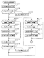
図25(A)は、図10に示された遊技制御処理において実行される普通図柄プロセス処理(ステップS27)を示すフローチャートである。普通図柄プロセス処理では、CPU56は、ステップS71のゲートスイッチ処理を実行した後に、普通図柄プロセスフラグの値に応じてステップS72〜S76に示された処理のうちのいずれかの処理を実行する。
FIG. 25A is a flowchart showing the normal symbol process (step S27) executed in the game control process shown in FIG. In the normal symbol process, the
ゲートスイッチ処理では、普通図柄変動開始の条件となるゲート32の打球通過にもとづくゲートスイッチ32aのオンを検出する。ゲートスイッチ32aがオンしていたら、普通図柄始動記憶が最大値(この例では「4」)に達しているか否か確認し、達していなければ、普通図柄始動記憶の値を+1する。なお、普通図柄始動記憶の値に応じて普通図柄始動記憶表示器41のLEDが点灯される。そして、CPU56は、普通図柄当り判定用乱数(ランダム5)の値を抽出し、その値を記憶する。なお、普通図柄始動記憶は、バックアップRAMに形成されている。
In the gate switch process, it is detected that the
ステップS72の普通図柄変動待ち処理では、CPU56は、普通図柄始動記憶の値が0以外であれば、普通図柄プロセスフラグの値を更新する。普通図柄始動記憶の値が0であれば何もしない。
In the normal symbol variation waiting process in step S72, the
図25(B)は、この実施の形態での普通図柄当り判定用乱数(ランダム7)と当り/はずれとの関係を示す説明図である。図25(B)に示すように、高確率のときには当り値は3〜12のいずれかであり、低確率のときには3、5または7である。普通図柄当り判定用乱数の値が当り値と一致すれば、当りと決定される。なお、普通図柄の高確率時は、例えば確変時と一致する。 FIG. 25 (B) is an explanatory diagram showing the relationship between the random numbers for normal symbol determination (random 7) and the hit / miss in this embodiment. As shown in FIG. 25B, the hit value is any of 3 to 12 when the probability is high, and is 3, 5 or 7 when the probability is low. If the value of the random number for determination per normal symbol matches with the winning value, it is determined as winning. It should be noted that the high probability of a normal symbol coincides with, for example, the probability change.
CPU56は、普通図柄判定処理(ステップS73)において、普通図柄始動記憶数=1に対応する乱数値格納エリアに格納されている値を読み出すとともに、普通図柄始動記憶の値を1減らし、かつ、各乱数値格納エリアの値をシフトする。そして、乱数値格納エリアから読み出した値、すなわち抽出されている普通図柄当り判定用乱数の値にもとづいて当り/はずれを決定する。すなわち、図21に示された関係にもとづいて当り/はずれを決定する。そして、所定の乱数等にもとづいて普通図柄の停止図柄を決定する。例えば、普通図柄が0〜9の数字である場合には、当り図柄が「3」,「7」であるとすると、当りとする場合には停止図柄を「3」または「7」に決定し、はずれの場合には「3」,「7」以外の値に決定する。当りと決定された場合には、普通図柄の可変表示が終了した後、可変入賞球装置15が開放される。
In the normal symbol determination process (step S73), the
なお、可変入賞球装置15の開放パターンは、例えば、低確率時には、可変入賞球装置15が1回だけ0.2秒間開放するようなパターンである。また、高確率時には、可変入賞球装置15が1.15秒間開放した後4.4秒の閉成期間をおいて再度1.15秒間開放するようなパターンである。可変入賞球装置15は、開放パターンに従って開閉制御される。なお、この実施の形態では、普通電動役物としての可変入賞球装置15は、始動入賞口14を開閉するための電動役物と兼用されている。
The opening pattern of the variable winning
図26は、図16および図17に示された判定用乱数更新処理によって変化するランダム5(普通図柄当り判定用乱数)を生成するためのカウンタの値の一例を示す説明図である。この例では、ランダム5の最初の値は3になっている。また、最初は初期値として「3」が設定されているので、カウント値が「13」まで進み、そこで+1されて値が3に戻ると(ステップS121,S122,S123)、ステップS124の処理でカウント値が初期値と一致したことが検出される。すると、ステップS125の処理でランダム8(ランダム5初期値決定用乱数)が抽出される。なお、この時点は、図26においてAで示されている。 FIG. 26 is an explanatory diagram showing an example of the value of the counter for generating random 5 (ordinary design random number per symbol) that is changed by the determination random number update process shown in FIGS. 16 and 17. In this example, the initial value of random 5 is 3. In addition, since “3” is initially set as an initial value, the count value advances to “13”, and when it is incremented by 1 and returns to 3 (steps S121, S122, and S123), the process of step S124 is performed. It is detected that the count value matches the initial value. Then, random 8 (random 5 initial value determination random number) is extracted in the process of step S125. This time point is indicated by A in FIG.
ここで、その時点のランダム8を生成するためのカウンタのカウント値が「11」であったとする。すると、ランダム8として「11」が抽出され、その値が保存されるとともに(ステップS126)、ランダム5を生成するためのカウンタにその値が設定される。従って、この時点から、ランダム5を生成するためのカウンタは、初期値「11」から歩進することになる。
Here, it is assumed that the count value of the counter for generating the random 8 at that time is “11”. Then, “11” is extracted as random 8 and the value is stored (step S126), and the value is set in the counter for generating random 5. Therefore, from this time point, the counter for generating the
ランダム5を生成するためのカウンタの値が歩進して「11」になると、ステップS124の処理でカウント値が初期値と一致したことが検出される。すると、ステップS125の処理でランダム8が抽出される。なお、この時点は、図26においてBで示されている。その時点のランダム8を生成するためのカウンタのカウント値が「8」であったとする。すると、ランダム8として「8」が抽出され、その値が保存されるとともに(ステップS126)、ランダム5を生成するためのカウンタにその値が設定される。従って、この時点から、ランダム5を生成するためのカウンタは、初期値「8」から歩進する。 When the value of the counter for generating random 5 advances to “11”, it is detected in step S124 that the count value matches the initial value. Then, random 8 is extracted by the process of step S125. This time point is indicated by B in FIG. Assume that the count value of the counter for generating random 8 at that time is “8”. Then, “8” is extracted as random 8 and the value is stored (step S126), and the value is set in the counter for generating random 5. Therefore, from this point, the counter for generating random 5 advances from the initial value “8”.
そして、ランダム5を生成するためのカウンタの値が歩進して「8」になると、ステップS124の処理でカウント値が初期値と一致したことが検出される。すると、ステップS125の処理でランダム8が抽出される。なお、この時点は、図26においてCで示されている。その時点のランダム8を生成するためのカウンタのカウント値が「m」であったとする。すると、ランダム8として「m」が抽出され、その値が保存されるとともに(ステップS126)、ランダム5を生成するためのカウンタにその値が設定される。従って、この時点から、ランダム5を生成するためのカウンタは、初期値「m」から歩進する。なお、図26において、星印(☆)は、カウント値が「5(当り判定値の一つ)」となる位置を示している。 When the value of the counter for generating random 5 advances to “8”, it is detected in step S124 that the count value matches the initial value. Then, random 8 is extracted by the process of step S125. This time point is indicated by C in FIG. Assume that the count value of the counter for generating random 8 at that time is “m”. Then, “m” is extracted as random 8, the value is stored (step S126), and the value is set in the counter for generating random 5. Therefore, from this point, the counter for generating random 5 advances from the initial value “m”. In FIG. 26, an asterisk (☆) indicates a position where the count value is “5 (one of hit determination values)”.
以上のように、ランダム5を生成するためのカウンタの値が1周(11カウント)する度に、カウント値として新たな初期値が設定され、以後、カウンタはその値から歩進していく。ランダム5を生成するためのカウンタ(普通図柄当り判定用カウンタ)の初期値を決定するためのカウンタ(ランダム8を生成するためのカウンタ)は、CPU56が実行する遊技制御処理の余り時間(遊技制御処理が終了してから次に2msタイマ割込が発生するまでの時間)でカウントアップされている。そして、その余り時間は、遊技の進行状況に応じて異なるので、ランダムな期間になっている。その結果、生成されるランダム8の値もランダムな値になるので、普通図柄当り判定用カウンタの初期値もランダムに変化する。 As described above, every time the value of the counter for generating random 5 makes one round (11 counts), a new initial value is set as the count value, and thereafter the counter advances from that value. A counter (counter for generating random 8) for determining an initial value of a counter for generating random 5 (ordinary symbol determination counter) is a surplus time for game control processing executed by the CPU 56 (game control). The time is counted up after the processing is completed until the next 2 ms timer interrupt is generated). The extra time varies depending on the progress of the game, and is a random period. As a result, the generated random 8 value also becomes a random value, so that the initial value of the normal symbol determination counter also changes randomly.
つまり、普通図柄当り判定用カウンタの値が1周する度に、ランダムな初期値からあらためてカウンタの歩進が始まる。すると、不正基板が主基板31に接続され、主基板31から出力される信号にもとづいて普通図柄当り判定用カウント値更新タイミングが認識されたとしても、普通図柄当り判定用カウント値が当り判定値になるタイミングをねらって不正な信号(ゲート32aの検出信号等)を主基板31に送り込むことは困難になる。この実施の形態によれば、図26に星印で示されたように、普通図柄当り判定用カウント値が当り判定値になるタイミングに規則性はなくランダムになっているからである。
That is, every time the value of the counter for normal symbol determination makes one round, the counter starts to increment from the random initial value. Then, even if the illegal board is connected to the
以上のように、この実施の形態では、遊技者が所定の遊技を行い、特定の条件成立に応じて遊技者にとって有利な特定遊技状態としての大当り遊技状態に制御可能であって、大当り遊技状態において、遊技球が特定領域としてのV入賞領域に入賞することによる継続条件の成立にもとづいて、所定のラウンド(この実施の形態では、1回の大入賞口の開放から閉成)を継続上限回数(この実施の形態では16回)に達するまで繰り返し継続させることが可能であり、大当り遊技状態におけるラウンドの継続上限回数の判定に用いられる判定用の数値を所定の数値範囲内で更新する上限回数用の判定用数値更新手段(この実施の形態ではランダム6を生成するためのカウンタ)と、所定の条件成立にもとづいて上限回数用の判定用数値更新手段の数値を抽出し、抽出された数値と所定の判定値(この実施の形態ではラウンド数決定用の判定値)とにもとづいて大当り遊技状態におけるラウンドの継続上限回数を決定する上限回数決定手段とを備え、上限回数用の判定用数値更新手段で更新される数値が所定の判定値と一致するタイミングが不定になるように制御する遊技機が実現される。なお、上限回数決定手段は、この実施の形態では、CPU56およびCPU56が実行するプログラムで実現される。特にステップS65の処理が、そのプログラムに相当する。
As described above, in this embodiment, a player plays a predetermined game and can be controlled to a big hit gaming state as a specific gaming state advantageous to the player according to the establishment of a specific condition. , A predetermined round (in this embodiment, from the opening of one big prize opening to the closing) is continued based on the establishment of the continuation condition by winning the game ball in the V winning area as the specific area It is possible to continue until the number of times (in this embodiment, 16 times) is reached, and the upper limit for updating the determination numerical value used for determining the upper limit number of rounds in the big hit gaming state within a predetermined numerical range Numerical value updating means for determination for the number of times (in this embodiment, a counter for generating random 6), and numerical value updating means for determination for the upper limit number of times based on satisfaction of a predetermined condition An upper limit number determining means for extracting a numerical value and determining the upper limit number of rounds in the big hit gaming state based on the extracted numerical value and a predetermined determination value (in this embodiment, a determination value for determining the number of rounds); In addition, a gaming machine that controls the timing at which the numerical value updated by the numerical value updating means for determination for the upper limit number coincides with a predetermined determination value is realized. In this embodiment, the upper limit number determining means is realized by the
また、この実施の形態では、ランダム6による抽選でラウンド上限回数を決定するものを例示したが、所定の抽選(例えば、乱数と判定値との比較)によって、特別可変入賞装置の内部構造を変化させるか否か、あるいは、変化させるタイミング(例えば変化させるラウンド)を決定するようにしてもよい。その場合、例えば、大入賞口(可変入賞球装置24)内に可動部材を設け、特定領域としてのV入賞領域に遊技球が入賞しやすい状態と入賞しがたい状態とに変化可能にすることによって実現することができる。また、内部構造を変化させるタイミングは、特定遊技状態としての大当り遊技状態中に生じてさせてもよいし、大当り遊技状態の終了後に生じてさせてもよい。 Further, in this embodiment, an example of determining the upper limit number of rounds by a random 6 lottery is illustrated, but the internal structure of the special variable winning device is changed by a predetermined lottery (for example, comparison between a random number and a determination value). It is also possible to determine whether or not to make the change, or change timing (for example, change round). In this case, for example, a movable member is provided in the big winning opening (variable winning ball apparatus 24) so that the game ball can be easily changed to a state where it is difficult to win in a V winning area as a specific area. Can be realized. The timing for changing the internal structure may be generated during the big hit gaming state as the specific gaming state, or may be generated after the big hit gaming state is ended.
実施の形態2.
上記の実施の形態では、第1種パチンコ遊技機を例にしたが、本発明は第2種パチンコ遊技機にも適用することができる。図27は、遊技盤201を示す正面図である。図27において、遊技盤201の表面には、発射された遊技球を誘導するための誘導レール202がほぼ円状に設置され、誘導レール202で区画された領域が遊技領域203を形成している。遊技領域203のほぼ中央には、可変入賞球装置220が配置されている。可変入賞球装置220の下方には、れぞれ始動玉検出器205a〜205c(始動検出手段)を内蔵した左・中・右の始動入賞口204a〜204cが配置されている。始動入賞口204a〜204cに遊技球が入賞すると、遊技球は始動玉検出器205a〜205cで検出される。検出に応じて、可変入賞球装置220が所定期間開放する。すなわち、始動入賞口204a〜204cは、遊技領域に設けられた始動領域に相当する。なお、始動入賞口204bは、可変入賞球装置15が開放状態になったときに、遊技球が入賞可能な状態になる。
In the above embodiment, the first type pachinko gaming machine is taken as an example, but the present invention can also be applied to a second type pachinko gaming machine. FIG. 27 is a front view showing the
遊技領域203には、ゲートスイッチ32aを内蔵したゲート32が設けられ、可変入賞球装置220における上部には、普通図柄表示器10が設けられている。普通図柄表示器10は、例えば0〜9の数字からなる普通図柄を可変表示する。さらに、普通図柄表示器10の近傍には、4つのLEDからなる普通図柄始動記憶表示器41が設けられている。ゲート32に遊技球が入賞すると、普通図柄表示器10において可変表示ができる状態であれば可変表示が開始され、可変表示ができる状態でなければ、普通図柄始動記憶(バックアップRAMに形成されている)が4に達していなければ、普通図柄始動記憶が1増やされるとともに、普通図柄始動記憶表示器41において点灯しているLEDが1つ増やされる。
In the
普通図柄表示器10における可変表示の表示結果(停止図柄)である場合には、可変入賞球装置15が所定回数、所定時間だけ開放状態になる。すなわち、始動入賞口204bに遊技球が入賞可能な状態になる。
When the display result of the variable display on the normal symbol display 10 (stop symbol), the variable winning
次に、可変入賞球装置220について、図28および図29を参照して説明する。可変入賞球装置220は、図28に示すように、始動入賞口204a〜204cのうち左右の始動入賞口204a,204cに入賞した場合には、可変入賞球装置220が1回開放され、始動入賞口204a〜204cのうち中央の始動入賞口204bに入賞した場合には、可変入賞球装置220が2回開放される。また、このように始動玉検出器205a〜205cの入賞検出に応じて可変入賞球装置220が開放動作を行う状態を始動動作状態という。また、遊技領域203には、上記した構成以外にも、風車ランプ207a,207bを内蔵した風車206a,206b、風車208a,208b、サイドランプ210a,210bを内蔵したサイドランプ飾り209a,209b、アウト口211等が設けられている。
Next, the variable winning
可変入賞球装置220を遊技盤201の表面に取り付けるための取付基板221を有し、取付基板221には、上部入賞空間222が形成されている。上部入賞空間222には、左右一対の開閉片223a,223bが回転可能に設けられている。開閉片223a,223bは、それぞれリンク機構を介してソレノイド224a,224bに連結され、ソレノイド224a,224bがオンしたときに、上部入賞空間222を開放する方向に回転する。また、ソレノイド224a,224bがオフしたときには、上部入賞空間222を閉鎖する方向に回転する。
An
上部入賞空間222の底壁部分には、上部入賞空間222に入賞した遊技球を検出する左右一対の入賞玉検出器225a,225bが設けられている。なお、入賞玉検出器225a,225bで検出された入賞玉は、入賞玉検出器225a,225bを通過した後、取付基板221の左右両側に形成された玉通路226a,226bを通って玉排出口227a,227bから下部入賞空間230に送り込まれる。
A pair of left and right winning
なお、図28および図29に示された可変入賞球装置220の構成は一例であって、内部構造を複数の状態(遊技球が可変入賞球装置220内に設けられている特定領域に入賞しやすい可変入賞球装置220の状態および入賞しにくい可変入賞球装置220の状態)に変化させうる可変入賞球装置であれば、どのような構成であってもよい。
The configuration of the variable winning
また、上部入賞空間222内の後面壁には、入賞玉検出器225a,225bによる入賞玉の検出数を表示する入賞個数表示器228と特定遊技状態におけるラウンドの継続回数を表示する継続回数表示器229が設けられている。なお、後述するように、入賞個数表示器228および継続回数表示器229には、所定の時期に、最大継続ラウンド数や確率状態に対応した識別情報としての図柄も表示される。すなわち、入賞個数表示器228および継続回数表示器229は、識別情報を表示するための可変表示装置も兼ねている。もちろん、識別情報を表示するための可変表示装置は、入賞個数表示器228および継続回数表示器229とは別個に設けられていてもよい。
In addition, on the rear wall in the upper winning
下部入賞空間230には、玉排出口227a,227bから送り込まれた入賞玉を後方に向かって転動させる下部転動盤231と、下部転動盤231の下流端に形成された開口232と、開口232を開閉する開閉板234と、開閉板234の上方位置で回転する回転ドラム236と、回転ドラム236の上端部後方に配された上部転動盤240が設けられている。開閉板234にはソレノイド235が連結され、ソレノイド235がオンしたときに開口232が閉鎖する方向に進出移動する。また、ソレノイド235がオフしたときに、開口232を開放する方向に退行移動する。
In the lower winning
回転ドラム236には各連結ギヤ237a〜237cを介してもモータ238が連結され、モータ238の駆動に応じて常時一定速度で一方向に回転するようになっている。ただし、モータ238が逆方向に回転することも可能である。
A
また、回転ドラム236の周面には、左・中・右の横一列3箇所に永久磁石239a〜239cが設置されている。従って、回転ドラム236は、開閉板234による開口232の閉鎖状態では、開口板234上に停留される遊技球を永久磁石239a〜239cの磁力によって吸引し、吸引した遊技球を回転動作に伴って上部転動板240に送り込む。
In addition,
上部転動板240の後方側には、中央を境として左右方向に下り傾斜する各傾斜部240a,240bが形成され、傾斜部240a,240bの下流側(左右両側)には、傾斜部240a,240bを転動した遊技球を再度下部転動板31上に送り込む玉通路241a,241bが形成されている。なお、傾斜部240a,240bは、後方側へも若干下り傾斜している。また、上部転動板240の後方中央には、特定領域としての特定受入口242が設けられ、特定受入口242の前方には、左右一対の可動部材243a,243bが設けられている。
On the rear side of the
可動部材243a,243bには、それぞれ回転軸244a,244bが一体的に取り付けられ、回転軸244a,244bの後端には、ソレノイド245を連結した連結部材246の各連動部246a,246bが一体的に取り付けられている。なお、連結部材246は、ソレノイド245を構成するプランジャ245aの進退動作を回転軸244a,244b(可動部材243a,243b)の回転動作に変換するものである。可動部材243a,243bは、ソレノイド245がオンしたときに、特定受入口242の前方を遮断する方向に回転する。また、ソレノイド245がオフしたときに、特定受入口242前方の遮断を解除する方向に回転する。
Rotating
特定受入口242の外周には、装飾用のLED表示器247が複数設けられる。また、特定受入口242の内部には、特定受入口242に入った入賞球を検出する特定検出手段としての特定玉検出器248が設けられている。特定玉検出器248の下流側には、検出した玉を開閉板234の下方位置を通して排出する図示しない玉通路が形成されている。なお、以下の説明では、遊技球が特定受入口242に入賞し特定玉検出器248で検出されたことをV入賞ともいう。
A plurality of
上述した構成において、可動部材243a,243bが特定受入口242の前方を遮断しない位置に維持される(上部に退避したまま)ことによって、可変入賞球装置220は、特定領域に遊技球が入賞しがたい状態になる。また、開閉板234が開口232を開放することによっても特定領域に遊技球が入賞しがたい状態にすることができる。
In the configuration described above, the
図30は、遊技機の裏面に設置されている遊技制御基板(主基板)31における回路構成の一例を示すブロック図である。なお、図30には、払出制御基板37、ランプ制御基板35、音制御基板70、発射制御基板91および図柄制御基板(以下、表示制御基板ともいう。)80も示されている。主基板31には、プログラムに従ってパチンコ遊技機を制御する基本回路53と、特定玉検出器248、始動玉検出器205a〜205c、入賞玉検出器225a,225bおよびクリアスイッチ921からの検出信号を基本回路53に与えるスイッチ回路58が搭載されている。
FIG. 30 is a block diagram showing an example of a circuit configuration of the game control board (main board) 31 installed on the back surface of the gaming machine. 30 also shows a
また、主基板31には、各ソレノイド224a,224b,235,245を基本回路53からの指令に従って駆動するソレノイド回路59と、モータ238を基本回路53からの指令に従って駆動するモータ回路60が搭載されている。また、基本回路53から与えられるデータに従って、大当りの発生を示す大当り情報等の情報出力信号をホールコンピュータ等の外部装置に対して出力する情報出力回路64が搭載されている。
The
基本回路53は、ゲーム制御用のプログラム等を記憶するROM54、ワークメモリとして使用される記憶手段(変動データを記憶する手段)としてのRAM55、プログラムに従って制御動作を行うCPU56およびI/Oポート部57を含む。この実施の形態では、ROM54,RAM55はCPU56に内蔵されている。すなわち、CPU56は、1チップマイクロコンピュータである。なお、1チップマイクロコンピュータは、少なくともRAM55が内蔵されていればよく、ROM54およびI/Oポート部57は外付けであっても内蔵されていてもよい。
The
また、RAM(CPU内蔵RAMであってもよい。)55の一部または全部が、電源基板910において作成されるバックアップ電源よってバックアップされているバックアップRAMである。すなわち、遊技機に対する電力供給が停止しても、所定期間は、RAM55の一部または全部の内容は保存される。
Further, a part or all of the RAM (may be a CPU built-in RAM) 55 is a backup RAM that is backed up by a backup power source created in the
なお、この実施の形態では、ランプ制御基板35に搭載されているランプ制御手段が、サイドランプ210a,210b、風車ランプ207a,207b、LED表示器247、その他枠装飾ランプ等の各種発光部材に制御信号を出力して各種発光部材の動作を所定態様で制御する。また、入賞個数表示器228および継続回数表示器229と、普通図柄表示器10の表示制御は、表示制御基板80に搭載されている表示制御手段によって行われる。また、音制御基板70に搭載されている音制御手段がスピーカ27の制御を行う。そして、景品としての遊技球の払い出しを行う球払出装置97は、払出制御基板37に搭載されている払出制御手段によって制御される。ランプ制御手段および音制御手段は一つの基板に搭載されていてもよい。さらに、表示制御手段、ランプ制御手段および音制御手段が一つの基板に搭載されていてもよい。
In this embodiment, the lamp control means mounted on the
また、実施の形態1の場合と同様に、遊技機裏面には、バックアップ電源も搭載された電源基板910等も設置されている。
Further, as in the case of the first embodiment, a
図31は、表示制御基板80内の回路構成を、普通図柄表示器10、入賞個数表示器228および継続回数表示器229、主基板51の出力ポート(ポート0,2)570,572および出力バッファ回路620,62Aとともに示すブロック図である。出力ポート(出力ポート2)572からは8ビットのデータが出力され、出力ポート570からは1ビットのストローブ信号(INT信号)が出力される。
FIG. 31 shows the circuit configuration in the
表示制御用CPU101は、制御データROM102に格納されたプログラムに従って動作し、主基板51からノイズフィルタ107および入力バッファ回路105Bを介してINT信号が入力されると、入力バッファ回路105Aを介して表示制御コマンドを受信する。入力バッファ回路105A,105Bとして、例えば汎用ICである74HC540,74HC14を使用することができる。なお、表示制御用CPU101がI/Oポートを内蔵していない場合には、入力バッファ回路105A,105Bと表示制御用CPU101との間に、I/Oポートが設けられる。そして、表示制御用CPU101は、受信した表示制御コマンドに従って、普通図柄表示器10、入賞個数表示器228および継続回数表示器229の表示制御を行う。
The
次に、遊技制御手段による可変入賞球装置220の作動制御について説明する。始動動作状態が発生すると、ソレノイド224a,224bが所定時間オンされて開閉片223a,223bが開放する。その開放作動中に遊技球が上部入賞空間222内に入賞すると、その入賞玉は入賞玉検出器225a,225bを通って下部入賞空間230に送り込まれる。また、開閉板234は、遊技制御手段によるソレノイド235のオン制御により、入賞玉検出器225a,225bが入賞玉を検出してから所定時間が経過するまで開口232を閉鎖する方向に移動する。そして、下部入賞空間230に送り込まれた遊技球は、開口232の閉鎖時間内で回転ドラム236のいずれかの永久磁石239a〜239cに吸引されると、回転ドラム236の回転に伴って上部転動板240に送り込まれる。
Next, the operation control of the variable winning
このとき、開閉板234上に停留された遊技球が左右の永久磁石239a,239cに吸引された場合、その遊技球は、100%の確率で玉通路241a,241bに送られる。なお、この時点で、開閉板234は、遊技制御手段によるソレノイド235のオフ制御により、開口232を開放する方向に移動している。そして、玉通路241a,241bに送られた玉は、下部転動板231を通って開口232を落下して排出される。一方、開閉板234上に停留された遊技球が中央の永久磁石239bに吸引された場合、その遊技球は、かなり高い確率(100%ではない)で特定受入口242に送られる。そして、特定受入口242に送られた遊技球(V入賞した遊技球)は、特定玉検出器248を通過した後に排出される。また、このとき、特定玉検出器248における遊技球の通過(特定玉検出器248による遊技球の検出)にもとづいて特定遊技状態が発生する。
At this time, when the game ball stopped on the opening /
特定遊技状態では、遊技制御手段がソレノイド235がオン/オフ制御することによって、開閉片223a,223bが所定時間の開放動作を18回繰り返す(18回の開閉サイクル)。なお、開閉サイクルが18回終了する以前に、入賞玉検出器225a,225bによって10個の入賞玉が検出された場合には、その時点で開閉片223a,223bの開閉動作を終了する。また、開閉片223a,223bの開閉サイクル中は、各ソレノイド235,245が常時オンされることで、開閉板234は常に開口232を閉鎖し、可動部材243a,243bは、最終サイクルを除き、常に特定受入口242の前方を遮断する(特定受入口242への入賞が不可となる)。
In the specific gaming state, the game control means controls the
よって、開閉サイクル中に可変入賞球装置220に入賞した遊技球は、開閉サイクルの終了時点までは開口232を落下することがない。従って、開閉板234上に停留された遊技球が左右の永久磁石239a,239cに吸引された場合、その遊技球は、玉通路241a,241bを通って下部転動板231に送り込まれ、再度開閉板234上に停留される。一方、開閉板234上に停留された遊技球が中央の永久磁石239bに吸引された場合、その入賞玉は、特定受入口242前方の可動部材243a,243bに受け止められる。
Therefore, the game ball that has won the variable winning
その後、開閉サイクルの終了に伴って(開閉サイクル終了後、入賞した遊技球が全て入賞玉検出器225a,225bに検出されるのに十分な時間を待って)、または、最終回の開閉サイクルにおいて、各ソレノイド235,245がオフされることで、開閉板234は開口232を開放し、可動部材243a,243bは特定受入口242前方の遮断を解除する。よって、可動部材243a,243bに受け止められた入賞玉は、上部転動板240を真直ぐ後方に転動して特定受入口242に入る。そして、特定受入口242に入った遊技球(V入賞した遊技球)が特定玉検出器248を通過することによって、18回の開閉サイクルの継続権が成立する。継続権が成立すると、所定のインターバル時間の経過後に再度開閉片223a,223bの開放サイクルが開始される。すなわち、次ラウンドが開始される。つまり、この実施の形態では、1ラウンドが18回の開閉サイクルで構成され、最終ラウンドを除く各ラウンド(18回の開閉サイクル)において遊技球が特定領域としての特定受入口242に入賞すると継続権が成立する。
Thereafter, with the end of the opening / closing cycle (after the opening / closing cycle, waiting for a sufficient time for all the winning game balls to be detected by the winning
ラウンドの継続回数は、最高15回(15ラウンド)まで許容されるようになっている。また、このような特定遊技状態において、継続回数表示器229は、開閉片223a,223bの継続回数(ラウンド回数)を表示し、入賞個数表示器228は、1ラウンド毎に入賞個数を表示する。
Up to 15 rounds (15 rounds) are allowed. In such a specific gaming state, the
次に遊技機の動作について説明する。主基板31における遊技制御手段(CPU56およびROM,RAM等の周辺回路)は、遊技機に対して電源が投入され、リセット端子の入力レベルがハイレベルになると、図9に示された処理と同様のメイン処理を開始する。
Next, the operation of the gaming machine will be described. Game control means (
メイン処理における初期化処理の実行(ステップS11〜S15)が完了した後、タイマ割込が発生すると、CPU56は、図32に示すレジスタの退避処理(ステップS80)を行った後、図32に示すステップS81〜S92の遊技制御処理を実行する。遊技制御処理において、CPU56は、まず、スイッチ回路58を介して、特定玉検出器248、始動玉検出器205a〜205cおよび入賞玉検出器225a,225bのスイッチの検出信号を入力し、それらの状態判定を行う(スイッチ処理:ステップS81)。
When the timer interrupt occurs after the execution of the initialization process (steps S11 to S15) in the main process is completed, the
次いで、パチンコ遊技機の内部に備えられている自己診断機能によって種々の異常診断処理が行われ、その結果に応じて必要ならば警報が発せられる(エラー処理:ステップS82)。 Next, various abnormality diagnosis processing is performed by a self-diagnosis function provided in the pachinko gaming machine, and an alarm is issued if necessary according to the result (error processing: step S82).
次に、遊技制御に用いられる当り判定用の乱数等の各判定用乱数を生成するための各カウンタのカウント値を更新する処理を行う(ステップS83)。CPU56は、さらに、表示用乱数および初期値用乱数を生成するためのカウンタのカウント値を更新する処理を行う(ステップS84,S85)。
Next, a process of updating the count value of each counter for generating each determination random number such as a hit determination random number used for game control is performed (step S83). The
なお、この実施の形態では、判定用乱数として、普通図柄当り判定用乱数、大当り遊技における最大継続ラウンド数を決定するための乱数(ラウンド数決定用乱数)、および特定遊技状態の終了後に可変入賞球装置20の内部構造をV入賞しやすくするか否か決定するための乱数(状態決定用乱数)がある。表示用乱数として、普通図柄表示器10における停止図柄を決定するための乱数があり、初期値用乱数として、普通図柄当り判定用乱数、ラウンド数決定用乱数および状態決定用乱数の初期値を決定するための乱数がある。
In this embodiment, as the random numbers for determination, a random number for determination per ordinary symbol, a random number for determining the maximum number of consecutive rounds in the big hit game (round number determination random number), and a variable prize after the end of the specific game state There is a random number (state determination random number) for determining whether or not the internal structure of the
さらに、CPU56は、プロセス処理を行う(ステップS86)。プロセス制御では、遊技状態に応じてパチンコ遊技機を所定の順序で制御するためのプロセスフラグに従って該当する処理が選び出されて実行される。そして、プロセスフラグの値は、遊技状態に応じて各処理中に更新される。
Further, the
また、普通図柄プロセス処理を行う(ステップS87)。普通図柄プロセス処理では、普通図柄表示器10の表示状態を所定の順序で制御するための普通図柄プロセスフラグに従って該当する処理が選び出されて実行される。そして、普通図柄プロセスフラグの値は、遊技状態に応じて各処理中に更新される。なお、普通図柄プロセス処理は、実施の形態1の場合(図25参照)と同様に実行可能である。
Further, normal symbol process processing is performed (step S87). In the normal symbol process, the corresponding process is selected and executed according to the normal symbol process flag for controlling the display state of the
次いで、CPU56は、表示制御コマンドをRAM55の所定の領域に設定して表示制御コマンドを送信する処理を行う(コマンド制御処理:ステップS88)。さらに、CPU56は、例えばホール管理用コンピュータに供給される大当り情報、始動情報情報などのデータを出力する情報出力処理を行う(ステップS89)。
Next, the
また、CPU56は、所定の条件が成立したときにソレノイド回路59に駆動指令を行う(ステップS90)。さらに、モータ38の駆動を指令する信号をモータ回路60に与える(ステップS91)。
Further, the
そして、CPU56は、入賞玉検出器225a,225b等の検出信号にもとづく賞球個数の設定などを行う賞球処理を実行する(ステップS92)。具体的には、入賞玉検出器225a,225b等がオンしたことにもとづく入賞検出に応じて、払出制御基板37に賞球個数を示す払出制御コマンドを出力する。払出制御基板37に搭載されている払出制御用CPU371は、賞球個数を示す払出制御コマンドに応じて球払出装置97を駆動する。その後、レジスタの内容を復帰させ(ステップS93)、割込許可状態に設定する(ステップS94)。
Then, the
以上の制御によって、この実施の形態では、遊技制御処理は2ms毎に起動されることになる。なお、この実施の形態では、タイマ割込処理で遊技制御処理が実行されているが、タイマ割込処理では例えば割込が発生したことを示すフラグのセットのみがなされ、遊技制御処理はメイン処理において実行されるようにしてもよい。 With the above control, in this embodiment, the game control process is started every 2 ms. In this embodiment, the game control process is executed by the timer interrupt process. However, in the timer interrupt process, for example, only a flag indicating that an interrupt has occurred is set, and the game control process is performed by the main process. May be executed.
図33は、CPU56が実行するプロセス処理のプログラムの一例を示すフローチャートである。図33に示すプロセス処理は、図32のフローチャートにおけるステップS86の具体的な処理である。
FIG. 33 is a flowchart illustrating an example of a process processing program executed by the
プロセス処理では、CPU56は、内部状態(この例ではプロセスフラグ)に応じて、ステップS500〜S508のうちのいずれかの処理を行う。ステップS500〜S508において、以下のような処理が行われる。
In the process processing, the
通常処理(ステップS500):始動玉検出器205a〜205cが遊技球を検出したか否か確認し、始動玉検出器205a〜205cによる検出があれば、ステップS501に移行するようにプロセスフラグの値を変更する。 Normal processing (step S500): It is confirmed whether or not the starting ball detectors 205a to 205c have detected a game ball. If there is detection by the starting ball detectors 205a to 205c, the value of the process flag is set so that the process proceeds to step S501. To change.
始動動作処理(ステップS501):所定期間および所定回数だけ可変入賞球装置220を開放するための制御を行うとともに、特定玉有効期間の設定(ソフトウェアによる設定)を行う。そして、可変入賞球装置220の開放期間が経過すると、可変入賞球装置220を閉鎖するための処理を行った後、ステップS502に移行するようにプロセスフラグの値を変更する。
Start-up operation processing (step S501): Control is performed for opening the variable winning
特定遊技状態判定処理(ステップS502):特定玉有効期間中にV入賞があったか否か確認する。V入賞があった場合には、大当りの発生として、特定玉有効期間経過後、大当り遊技(特定遊技状態)における最大継続ラウンド数および大当り遊技後の遊技状態に関する確率状態の抽選を行い、ステップS503に移行するようにプロセスフラグの値を変更する。V入賞がなかった場合には、ステップS500に移行するようにプロセスフラグの値を変更する。 Specific game state determination process (step S502): It is confirmed whether or not there is a V prize during the specific ball valid period. If there is a V-winning, as the occurrence of the big win, after the specific ball valid period has elapsed, the maximum number of consecutive rounds in the big hit game (specific game state) and the probability state regarding the game state after the big hit game are drawn, step S503 Change the value of the process flag to shift to. If there is no V prize, the value of the process flag is changed so as to proceed to step S500.
ラウンド開始前処理(ステップS503):表示制御基板80やランプ制御基板35に対して、ラウンド開始を指示するためのコマンドを送信する。その後、ステップS504に移行するようにプロセスフラグの値を変更する。
Pre-round start process (step S503): A command for instructing the start of a round is transmitted to the
ラウンド中処理(ステップS504):開閉サイクルが18回終了か、または、入賞玉検出器225a,225bによって10個の入賞玉が検出されたか否かを監視する。開閉サイクルが18回終了するか、または、開閉サイクルが18回終了する以前に入賞玉検出器225a,225bによって10個の入賞玉が検出された場合には、ステップS505に移行するようにプロセスフラグの値を変更する。
In-round processing (step S504): It is monitored whether the open / close cycle has ended 18 times or whether ten winning balls are detected by the winning
V入賞確認処理(ステップS505):最大継続ラウンド数に達していない場合には、V入賞があったか否か確認し、V入賞があればステップS503に移行するようにプロセスフラグの値を変更する。V入賞がなければ、ステップS506に移行するようにプロセスフラグの値を変更する。また、最大継続ラウンド数に達している場合も、ステップS506に移行するようにプロセスフラグの値を変更する。 V-winning confirmation process (step S505): If the maximum number of consecutive rounds has not been reached, it is confirmed whether or not there is a V-winning. If there is a V-winning, the value of the process flag is changed so that the process proceeds to step S503. If there is no V prize, the value of the process flag is changed so as to proceed to step S506. Even when the maximum number of continuous rounds has been reached, the value of the process flag is changed so as to proceed to step S506.
なお、最終ラウンド(最大継続ラウンド数に一致する回のラウンド)では、遊技制御手段は、可変入賞球装置220の内部構造を変化させる。例えば、可動部材243a,243bを特定受入口242の前方を遮断しない位置に維持する(上部に退避したまま)ことによって、可変入賞球装置220を、特定領域に遊技球が入賞しがたい状態にする。また、遊技制御手段は、最終ラウンドにおいて、特定領域に遊技球が入賞しても無視する。すなわち、最終ラウンドでは、ソフトウェア的に特定領域に遊技球が入賞しない状態が設定される。
Note that in the final round (the round that matches the maximum number of consecutive rounds), the game control means changes the internal structure of the variable winning
特定遊技状態終了処理(ステップS506):表示制御基板80やランプ制御基板35に対して、特定遊技状態終了を指示するためのコマンドを送信する。また、ステップS502で決定されている確率状態を報知するための制御を行う。具体的には、表示制御基板80に対して、確率状態を報知するための可変表示装置228,229における図柄の変動(この例では、「1」〜「9」の数字が可変表示されるとする。)を指示する表示制御コマンドと停止図柄を指示する表示制御コマンドを送信する。その後、ステップS507に移行するようにプロセスフラグの値を変更する。
Specific gaming state end process (step S506): A command for instructing the end of the specific gaming state is transmitted to the
図柄変動中処理(ステップS507):図柄変動の変動期間が経過したら、ステップS508に移行するようにプロセスフラグの値を変更する。 Symbol variation processing (step S507): When the variation period of symbol variation elapses, the value of the process flag is changed so as to proceed to step S508.
図柄停止処理(ステップS508):表示制御基板80に対して、図柄の変動の停止を指示する表示制御コマンドを送信する。また、確率状態に関する内部フラグ(後述する高確変フラグや中確変フラグ)を設定する。その後、ステップS500に移行するようにプロセスフラグの値を変更する。
Symbol stop processing (step S508): A display control command for instructing stop of symbol variation is transmitted to the
図34は、各乱数を示す説明図である。各乱数は、以下のように使用される。
(1)ランダム5:普通図柄表示器10における普通図柄にもとづく当りを発生させるか否か決定する(普通図柄当た判定用)
(2)ランダム6:大当り遊技における最大継続ラウンド数を決定する(ラウンド数決定用)
(3)ランダム8:ランダム5の初期値を決定する(ランダム5初期値決定用)
(4)ランダム9:ランダム6の初期値を決定する(ランダム6初期値決定用)
(5)ランダム10:大当り遊技終了後の遊技状態を決定する(状態決定用)
(6)ランダム11:ランダム10の初期値を決定する(ランダム10初期値決定用)
FIG. 34 is an explanatory diagram showing each random number. Each random number is used as follows.
(1) Random 5: Determines whether or not to generate a hit based on the normal symbol on the normal symbol display 10 (for determination of hitting the normal symbol)
(2) Random 6: Determine the maximum number of consecutive rounds in the jackpot game (for determining the number of rounds)
(3) Random 8: Determine initial value of random 5 (for determining random 5 initial value)
(4) Random 9: Determine initial value of random 6 (for determining random 6 initial value)
(5) Random 10: Determine the gaming state after the big hit game (for state determination)
(6) Random 11: Determine an initial value of random 10 (for determining an initial value of random 10)
なお、図32に示された遊技制御処理におけるステップS83では、CPU56は、(1)の普通図柄当た判定用乱数、(2)のラウンド数決定用乱数および(5)の状態決定用を生成するためのカウンタのカウントアップ(1加算)を行う。すなわち、それらが判定用乱数であり、それら以外の乱数が表示用乱数または初期値用乱数である。なお、遊技効果を高めるために、上記(1)〜(6)の乱数以外の普通図柄に関する乱数等も用いられている。また、図34に示された各乱数値のとりうる範囲も一例であって、他の範囲を用いることもできる。
In step S83 in the game control process shown in FIG. 32, the
図35は、ラウンド数決定用乱数(ランダム5)と最大継続ラウンド数を決定するための判定値との関係の一例を示す説明図である。図35に示すように、この実施の形態では、最大継続ラウンド数として、8〜15ラウンドのいずれかに決定される。すなわち、抽出されたランダム5の値が図35の右欄に示された値に一致すると、左欄に示された最大継続ラウンド数が決定される。 FIG. 35 is an explanatory diagram showing an example of the relationship between the round number determination random number (random 5) and the determination value for determining the maximum number of continuous rounds. As shown in FIG. 35, in this embodiment, the maximum number of continuous rounds is determined as one of 8 to 15 rounds. That is, when the extracted random 5 value matches the value shown in the right column of FIG. 35, the maximum number of continuous rounds shown in the left column is determined.
決定された最大継続ラウンド数は、例えば、大当り遊技が開始される前に、入賞個数表示器228および継続回数表示器229において表示される。その場合、決定結果のみを表示してもよいが、図柄の可変表示等の演出を行ってから決定結果を表示してもよい。また、大当り遊技に開始前には、決定された最大継続ラウンド数よりも少ない数を表示し、各ラウンドの開始前に数が増えた数を表示し、最大継続ラウンドに対応した最終ラウンドよりも前のラウンド開始前に最大継続ラウンド数を表示するようにしてもよい。そのような表示を行った場合には、遊技者には徐々に増えていく数が報知されるので、遊技者の期待感をラウンド消化に伴って高めていくことができる。
The determined maximum continuation round number is displayed on the winning
図36は、抽出されたランダム10(状態決定用乱数)の値と確率状態との関係の一例を示す説明図である。高確率状態とは、大当り遊技が終了した後において、中確率状態よりもV入賞しやすい状態である。中確率状態とは、大当り遊技が終了した後において、低確率状態よりもV入賞しやすい状態である。 FIG. 36 is an explanatory diagram showing an example of the relationship between the value of the extracted random 10 (random number for state determination) and the probability state. The high probability state is a state in which V winning is easier than the medium probability state after the big hit game is finished. The medium probability state is a state in which V winning is easier than the low probability state after the big hit game is finished.
遊技制御手段は、上述したステップS502において、ランダム10を抽出し、抽出値と図36に示された関係にもとづいて、すなわち抽出値と図36の左欄に記載されている判定値(0〜11)とを比較して、大当り遊技終了後の遊技状態を決定する。なお、決定結果は、大当り遊技の終了後に、可変表示装置228,229を用いて遊技者に報知される。図36に示された報知図柄とは、大当り遊技終了後の遊技状態の決定結果を報知するための図柄である。その場合、決定結果のみを表示してもよいが、この実施の形態では、図柄の可変表示等の演出を行ってから決定結果が表示される。
In step S502 described above, the game control means extracts random 10, and based on the extracted value and the relationship shown in FIG. 36, that is, the extracted value and the determination value (0 to 0) described in the left column of FIG. 11) and the game state after the big hit game is determined. The determination result is notified to the player using the
図37は、図32に示された遊技制御処理で実行される判定用乱数更新処理(ステップS83)の一例を示すフローチャートである。判定用乱数更新処理において、CPU56は、ランダム5(普通図柄当り判定用乱数)を生成するためのカウンタの値を+1する(ステップS201)。ランダム5を生成するためのカウンタの値が(最大値+1)以上になっている場合には(ステップS202)、カウント値を3に戻す(ステップS203)。なお、この実施の形態では、(最大値+1)は14である。
FIG. 37 is a flowchart showing an example of the determination random number update process (step S83) executed in the game control process shown in FIG. In the determination random number update process, the
ランダム5を生成するためのカウンタの値が初期値としてランダム5用初期値バッファに保存されている値と一致したか否か確認する(ステップS204)。一致していなければ、カウント値はそのままである。一致していた場合には、ランダム8(ランダム5初期値決定用乱数)を抽出する(ステップS205)。すなわち、ランダム8を生成するためのカウンタのカウント値を入力する。そして、抽出された値を初期値としてランダム5用初期値バッファに保存するとともに(ステップS206)、抽出された値を、ランダム5を生成するためのカウンタに設定する(ステップS207)。よって、この時点で、ランダム5を生成するためのカウンタの初期値が変更される。なお、遊技機に電源が投入されたときには一般には初期値として「3」がランダム用初期値バッファに保存されるが、バックアップRAMにランダム5の値が保存されていた場合には電源投入時に保存値に戻される。また、ランダム5用初期値バッファもバックアップRAMに形成される。遊技制御手段は、電力供給が復旧した場合に、変動データ記憶手段に保持されている数値にもとづいて、数値の更新を継続する。
It is confirmed whether or not the value of the counter for generating random 5 matches the value stored in the initial value buffer for random 5 as an initial value (step S204). If they do not match, the count value remains unchanged. If they match, random 8 (random 5 initial value determination random number) is extracted (step S205). That is, the count value of the counter for generating random 8 is input. Then, the extracted value is stored as an initial value in the initial value buffer for random 5 (step S206), and the extracted value is set in a counter for generating random 5 (step S207). Therefore, at this time, the initial value of the counter for generating random 5 is changed. When the power is turned on to the gaming machine, “3” is generally stored in the random initial value buffer as an initial value, but when the
また、ランダム6(ラウンド数決定用乱数)を生成するためのカウンタの値を+1する(ステップS211)。ランダム6を生成するためのカウンタの値が(最大値+1)以上になっている場合には(ステップS212)、カウント値を0に戻す(ステップS213)。なお、この実施の形態では、(最大値+1)は19である。 Also, the counter value for generating random 6 (round number determination random number) is incremented by 1 (step S211). When the value of the counter for generating the random 6 is equal to or greater than (maximum value + 1) (step S212), the count value is returned to 0 (step S213). In this embodiment, (maximum value + 1) is 19.
そして、CPU56は、ランダム6を生成するためのカウンタの値が初期値としてランダム6用初期値バッファに保存されている値と一致したか否か確認する(ステップS214)。一致していなければ、カウント値はそのままである。一致していた場合には、ランダム9(ランダム6初期値決定用乱数)を抽出する(ステップS215)。すなわち、ランダム9を生成するためのカウンタのカウント値を入力する。そして、抽出された値を初期値としてランダム6用初期値バッファに保存するとともに(ステップS216)、抽出された値を、ランダム6を生成するためのカウンタに設定する(ステップS217)。よって、この時点で、ランダム6を生成するためのカウンタの初期値が変更される。なお、遊技機に電源が投入されたときに初期値として「0」がランダム6を生成するためのカウンタに設定されるが、バックアップRAMにランダム6の値が保存されていた場合には電源投入時に保存値に戻される。また、ランダム6用初期値バッファもバックアップRAMに形成される。
Then, the
さらに、ランダム10(状態決定用乱数)を生成するためのカウンタの値を+1する(ステップS221)。ランダム10を生成するためのカウンタの値が(最大値+1)以上になっている場合には(ステップS222)、カウント値を0に戻す(ステップS223)。なお、この実施の形態では、(最大値+1)は12である。 Further, the counter value for generating random 10 (random number for state determination) is incremented by 1 (step S221). When the value of the counter for generating the random 10 is equal to or greater than (maximum value + 1) (step S222), the count value is returned to 0 (step S223). In this embodiment, (maximum value + 1) is 12.
そして、CPU56は、ランダム10を生成するためのカウンタの値が初期値としてランダム10用初期値バッファに保存されている値と一致したか否か確認する(ステップS224)。一致していなければ、カウント値はそのままである。一致していた場合には、ランダム11(ランダム10初期値決定用乱数)を抽出する(ステップS225)。すなわち、ランダム11を生成するためのカウンタのカウント値を入力する。そして、抽出された値を初期値としてランダム10用初期値バッファに保存するとともに(ステップS226)、抽出された値を、ランダム10を生成するためのカウンタに設定する(ステップS227)。よって、この時点で、ランダム10を生成するためのカウンタの初期値が変更される。なお、遊技機に電源が投入されたときに初期値として「0」がランダム10を生成するためのカウンタに設定されるが、バックアップRAMにランダム10の値が保存されていた場合には電源投入時に保存値に戻される。また、ランダム10用初期値バッファもバックアップRAMに形成される。遊技制御手段は、電力供給が復旧した場合に、変動データ記憶手段に保持されている数値にもとづいて、数値の更新を継続する。
Then, the
図39は、図32に示された遊技制御処理において1回実行されるとともに(ステップS85)、図9に示されたメイン処理における割込余り時間(遊技制御処理終了後、次回の2msタイマ割込が発生するまでの時間)で繰り返し実行される(ステップS18)初期値用乱数更新処理の一例を示すフローチャートである。 FIG. 39 is executed once in the game control process shown in FIG. 32 (step S85), and the interrupt surplus time in the main process shown in FIG. It is a flowchart showing an example of an initial value random number update process (step S18) that is repeatedly executed at a time until the occurrence of the error.
初期値用乱数更新処理において、CPU56は、ランダム8(ランダム5初期値決定用乱数)を生成するためのカウンタの値を+1する(ステップS231)。ランダム8を生成するためのカウンタの値が(最大値+1)以上になっている場合には(ステップS232)、カウント値を3に戻す(ステップS233)。なお、(最大値+1)は、ランダム5の場合と同様に14である。
In the initial value random number update process, the
また、CPU56は、ランダム9(ランダム6初期値決定用乱数)を生成するためのカウンタの値を+1する(ステップS234)。ランダム9を生成するためのカウンタの値が(最大値+1)以上になっている場合には(ステップS235)、カウント値を0に戻す(ステップS236)。なお、(最大値+1)は、ランダム6の場合と同様に19である。
Further, the
そして、CPU56は、ランダム11(ランダム10初期値決定用乱数)を生成するためのカウンタの値を+1する(ステップS237)。ランダム11を生成するためのカウンタの値が(最大値+1)以上になっている場合には(ステップS238)、カウント値を0に戻す(ステップS239)。なお、(最大値+1)は、ランダム10の場合と同様に12である。
Then, the
図40は、プロセス処理におけるステップS508(図柄停止処理)の一例を示すフローチャートである。図柄停止処理(大当り遊技終了後の遊技状態を報知するための図柄変動による演出を停止させる処理)において、CPU56は、表示制御基板80に対して、図柄の変動停止を示す確定コマンドを送信する処理を行う(ステップS581)。次いで、既に確変状態(高確率状態、中確率状態または低確率状態)にあるのか否か確認する(ステップS582)。確変状態にあれば、高確変フラグ、中確率フラグおよび低確率フラグをリセットする(ステップS583)。そして、プロセスフラグを通常処理(ステップS500)に対応した値に更新し(ステップS586)、図柄停止終了処理を終了する。
FIG. 40 is a flowchart showing an example of step S508 (design stop processing) in the process processing. In the symbol stop processing (processing for stopping the effect due to symbol variation for notifying the game state after the end of the big hit game), the
確変状態でなければ、可変表示装置228,229に表示された停止図柄が高確変図柄(この例では「1」、「3」または「7」、図36参照)であったか否か確認する(ステップS584)。高確変図柄であった場合には、高確変フラグをセットする(ステップS585)。そして、プロセスフラグを通常処理(ステップS500)に対応した値に更新し(ステップS586)、図柄停止終了処理を終了する。
If it is not the probability variation state, it is confirmed whether or not the stop symbol displayed on the
また、停止図柄が中確変図柄であった場合には(ステップS587)、中確変フラグをセットする(ステップS587)。そして、プロセスフラグを通常処理(ステップS500)に対応した値に更新し(ステップS586)、図柄停止終了処理を終了する。 If the stop symbol is a medium probability variation symbol (step S587), a medium probability variation flag is set (step S587). Then, the process flag is updated to a value corresponding to the normal process (step S500) (step S586), and the symbol stop end process is ended.
停止図柄が低確率図柄(高確変図柄でも中確変図柄でもない図柄)であった場合には、低確変フラグをセットする(ステップS589)。そして、プロセスフラグを通常処理(ステップS500)に対応した値に更新し(ステップS586)、図柄停止終了処理を終了する。 If the stop symbol is a low-probability symbol (a symbol that is neither a high-probability variation nor a medium-probability variation symbol), a low-probability variation flag is set (step S589). Then, the process flag is updated to a value corresponding to the normal process (step S500) (step S586), and the symbol stop end process is ended.
以上のように、この実施の形態では、遊技制御手段の一部である状態決定手段(具体的にはソフトウェアで実現されている。)が、所定の乱数(ランダム10)にもとづいて、高確率状態とするのか、中確率状態とするのか、低確率状態とするのか決定する。そして、特定遊技状態が終了した後に、遊技制御手段は、状態決定手段の決定結果にもとづいて、実際に、高確率状態、中確率状態または低確率状態にする。それぞれの状態は、可変入賞球装置220の内部構造を変化させることによって実現される。なお、高確率状態は、高確変フラグがセットされている状態であり、中確率状態は、中確変フラグがセットされている状態であり、低確率状態は、低確変フラグがセットされている状態である。
As described above, in this embodiment, the state determining means (specifically, realized by software) which is a part of the game control means has a high probability based on a predetermined random number (random 10). It is determined whether it is a state, a medium probability state, or a low probability state. Then, after the specific game state is ended, the game control means actually sets the high probability state, the medium probability state, or the low probability state based on the determination result of the state determination means. Each state is realized by changing the internal structure of the variable winning
そして、次に特定遊技状態が生ずると、確変状態(高確率状態、中確率状態または低確率状態)は終了する。 Then, when a specific gaming state occurs next, the probability variation state (high probability state, medium probability state, or low probability state) ends.
なお、この実施の形態では、特定遊技状態が終了してから可変表示装置228,229における図柄の変動による報知が行われたが、状態決定手段による決定にもとづく確率状態の設定は特定遊技状態の終了後に行われるものの、確率状態に関する報知は特定遊技状態の前に行われるようにしてもよい。
In this embodiment, after the specific gaming state has ended, the
図41は、高確変フラグ、中確変フラグおよび低確変フラグのセット状態に応じた可変入賞球装置220の状態の変化(内部構造の変化)を説明するためのタイミング図である。図41(A)に示すように、低確率状態では、始動玉検出器による遊技球の検出に応じて可変入賞球装置220(具体的には開閉片223a,223b)がソレノイド224a,224bによって所定期間開放し、ソレノイド235によって開口235が所定期間閉鎖状態になる。また、可動部材243a,243bが特定受入口242の前方を遮断しない位置に維持される(上部に退避したまま)。従って、遊技球は特定受入口242の前方において可動部材243a,243bに受け止められないので、比較的遊技球が特定受入口242に入賞しがたい状態になる。すなわち、比較的V入賞しがたい状態になる。
FIG. 41 is a timing chart for explaining a change in the state of the variable winning ball device 220 (change in internal structure) in accordance with the set state of the high probability variation flag, the medium probability variation flag, and the low probability variation flag. As shown in FIG. 41A, in the low probability state, the variable winning ball device 220 (specifically, the open /
図41(B)に示すように、中確率状態では、始動玉検出器による遊技球の検出に応じて可変入賞球装置220(具体的には開閉片223a,223b)がソレノイド224a,224bによって所定期間開放し、ソレノイド235によって開口235が所定期間閉鎖状態になる。ただし、閉鎖状態にある所定期間は、低確率状態の場合比べて長い。開口32の閉鎖状態では、開口板34上に停留される遊技球が回転ドラム236における永久磁石239a〜239cの磁力によって吸引され、回転ドラム236の回転動作に伴って上部転動板240に送り込まれるのでV入賞が可能な状態になる。閉鎖状態にある所定期間が低確率状態の場合比べて長いので、中確率状態は、低確率状態よりもV入賞しやすい状態になる。また、ソレノイド245によって、可動部材243a,243bが、特定受入口242の前方を遮断する位置に移動され(上方から下方に移動され)、所定期間、その状態が維持される。従って、遊技球が特定受入口242の前方において可動部材243a,243bに受け止められる期間が生じ、このことからも、中確率状態は、低確率状態よりもV入賞しやすい状態になる。
As shown in FIG. 41 (B), in the medium probability state, the variable winning ball device 220 (specifically, the open /
図41(C)に示すように、高確率状態では、始動玉検出器による遊技球の検出に応じて可変入賞球装置220(具体的には開閉片223a,223b)がソレノイド224a,224bによって所定期間開放するとともに、ソレノイド235によって開口235が所定期間閉鎖状態になる。閉鎖状態にある所定期間は、中確率状態の場合比べて長い。従って、高確率状態は、中確率状態よりもV入賞しやすい状態になる。また、ソレノイド245によって、可動部材243a,243bが、特定受入口242の前方を遮断する位置に維持される。従って、このことからも、高確率状態は、中確率状態よりもV入賞しやすい状態になる。
As shown in FIG. 41 (C), in the high probability state, the variable winning ball device 220 (specifically, the open /
なお、可変入賞球装置220は、始動玉検出器の検出に応じて複数回開放することがあるが、図41には、1回だけ開放する場合が例示されている。また、低確率状態は、確変状態(高確率状態、中確率状態または低確率状態)ではない通常状態よりもV入賞しがたい状態であり、通常状態は中確変状態よりもV入賞しがたい状態であるが、低確率状態を通常状態と同じ状態にしてもよい。
The variable winning
また、この実施の形態では、上述したように、大当り遊技状態における最大継続ラウンド数(ランダム6にもとづいて決定されたラウンド)に対応したラウンドにおいて、可変入賞球装置220がV入賞しがたい状態に設定される。そして、その場合、可動部材243a,243bを特定受入口242の前方を遮断しない位置に維持する(上部に退避したまま)ことによってV入賞しがたい状態にすることを例示したが、最大継続ラウンド数に対応したラウンドにおいて、可動部材243a,243bを制御するするだけでなく、図41(A)に示されたように、さらに開口232も制御することによってV入賞しがたい状態にするようにしてもよい。
In this embodiment, as described above, in the round corresponding to the maximum number of consecutive rounds in the jackpot gaming state (round determined based on random 6), it is difficult for the variable winning
以上に説明したように、この実施の形態では、普通図柄当り判定用乱数(ランダム5)、ラウンド数決定用乱数(ランダム6)および状態決定用乱数(ランダム10)を生成するためのカウンタのカウント値が1周すると、初期値用乱数が抽出され、初期値用乱数の値にもとづいて、ランダム5、ランダム6およびランダム10を生成するためのカウンタの初期値が変更される。ランダム5、ランダム6およびランダム10を生成するためのカウンタの初期値がランダムになるので、遊技機に不正基板を搭載する等の手段によって例えば主基板31から出力される信号を観測できたとしても、その信号にもとづいて、普通図柄の当り判定値に一致するランダム5の値が発生するタイミング、最も大きい最大継続ラウンド数に応じたランダム6の値が発生するタイミング、大当り遊技終了後に高確率状態とする数に応じたランダム10の値が発生するタイミングを検知することは困難である。
As described above, in this embodiment, the counter count for generating the random number for determining normal symbols (random 5), the random number for determining the round number (random 6), and the random number for determining the state (random 10) is determined. When the value makes one round, the initial value random number is extracted, and the initial value of the counter for generating random 5, random 6 and random 10 is changed based on the value of the initial value random number. Since the initial value of the counter for generating random 5, random 6 and random 10 becomes random, even if a signal output from the
以上のように、この実施の形態では、遊技者が所定の遊技を行い、特定の条件成立に応じて遊技者にとって有利な所定回数のラウンド(この実施の形態では、18回の開閉サイクルで構成される)からなる特定遊技状態に制御可能であって、特定遊技状態において、遊技球が特定領域としての特定受入口242に入賞することによる継続条件の成立にもとづいて、所定のラウンドを継続上限回数(この実施の形態では15回)に達するまで繰り返し継続させることが可能であり、特定遊技状態におけるラウンドの継続上限回数の判定に用いられる判定用の数値を所定の数値範囲内で更新する上限回数用の判定用数値更新手段(この実施の形態ではランダム6を生成するためのカウンタ)と、所定の条件成立にもとづいて上限回数用の判定用数値更新手段の数値を抽出し、抽出された数値と所定の判定値(この実施の形態ではラウンド数決定用の判定値)とにもとづいて大当り遊技状態におけるラウンドの継続上限回数を決定する上限回数決定手段とを備え、上限回数用の判定用数値更新手段で更新される数値が所定の判定値と一致するタイミングが不定になるように制御する遊技機が実現される。その結果、特別可変入賞装置を第1の状態(遊技者にとって有利な状態)に制御する特定遊技状態におけるラウンド数を決定するために用いられる数値が所定の値に一致するタイミングを遊技機外部から特定することを困難にすることができる。なお、上限回数決定手段は、この実施の形態では、CPU56およびCPU56が実行するプログラムで実現される。特にステップS502における処理が、そのプログラムに相当する。
As described above, in this embodiment, a player plays a predetermined game, and a predetermined number of rounds advantageous to the player when a specific condition is satisfied (in this embodiment, the game is configured with 18 opening / closing cycles. To the specified gaming state, and in the specified gaming state, the upper limit of the predetermined round is set based on the establishment of the continuation condition when the game ball wins the specified
実施の形態3.
上記の各実施の形態では、第1種パチンコ遊技機または第2種パチンコ遊技機を例にしたが、本発明は第3種パチンコ遊技機にも適用することができる。図42は第3種パチンコ遊技機の遊技盤501を正面からみた正面図である。遊技盤501は、パチンコ遊技機の本体に着脱可能に取付けられる。
In each of the above embodiments, the first type pachinko gaming machine or the second type pachinko gaming machine is taken as an example, but the present invention can also be applied to a third type pachinko gaming machine. FIG. 42 is a front view of the
打球発射装置から発射された遊技球は、外レール501と内レール502との間を通って遊技領域507に入り、その後、遊技領域507を下りてくる。遊技球がゲート511を通過しゲートスイッチ511aで検出されると、普通図柄表示器510における可変表示が開始される。この実施の形態では、普通図柄表示器510は、それぞれに図柄(この例では、○と×)が描かれた2つのランプからなり、2つのランプが交互に点灯することによって可変表示がなされる。そして、○のランプが停止した状態で可変表示が終了すると当りとなる。
The game ball launched from the hitting ball launching device passes between the
当りとなった場合には、普通電動役物550が作動して特定入賞口532が開放した状態になる。遊技球が特定入賞口532に入賞した遊技球は特定入賞口スイッチ532aで検出されるととともに、振分部材535に入る。その後、誘導部540における特別装置作動判定図柄ゲート541を通過すると、可変表示装置512において判定図柄が可変表示を始める。なお、特別装置作動判定図柄ゲート541の部分には、特別装置作動判定図柄ゲート541を通過した遊技球を検出する作動検出手段としての図柄ゲートスイッチ541aが設けられている。また、可変表示装置512における判定図柄の変動中では、遊技球は、特別装置作動判定図柄ゲート541の下方の誘導部材542の凹部に貯留している。
When winning, the ordinary electric accessory 550 is activated and the specific winning opening 532 is opened. The game ball in which the game ball has won the specific winning port 532 is detected by the specific winning port switch 532a and enters the sorting member 535. Thereafter, when the special device operation determination symbol gate 541 in the
なお、遊技領域507において、普通入賞口513,514,515,516に入賞した遊技球は、それぞれ、入賞口スイッチ513a,514a,515a,516aで検出される。入賞口スイッチ513a,514a,515a,516aおよび特定入賞口スイッチ532aで遊技球が検出されると、所定個の遊技球が景品として払い出される。
In the
可変表示装置512における判定図柄の可変表示結果(停止図柄)が当り図柄であると当りが発生し、誘導部材542の凹部に貯留していた遊技球が誘導装置によって特別装置作動領域544に誘導される。そして、特別装置作動領域544に設けられているセンサ544aによって検知されると権利が発生し、権利発生状態において遊技球が始動入賞装置520における始動口(始動領域の一例)に入賞すると、その遊技球は始動口スイッチ520aによって検出される。すると、大入賞口が開放して遊技球が入賞しやすい特定遊技状態(大当り遊技状態)に移行する。可変表示装置512における判定図柄の可変表示結果(停止図柄)がはずれ図柄であった場合には、誘導部材542の凹部に停留していた遊技球は、通常領域543に誘導される。なお、始動入賞装置520には回転体521が設けられ、始動入賞装置520における回転体521の下部には、特別電動役物を形成する大入賞口を開放するための開閉板551を有する可変入賞球装置555が設けられている。遊技球が回転体521によって回転させられ始動口スイッチ520aによって検出されると始動口に入賞したことになる。また、開閉板551が開放状態になることによって大入賞口が開放される。
If the variable display result (stop symbol) of the determination symbol in the variable display device 512 is a hit symbol, a hit occurs, and the game ball stored in the recess of the
各開放期間(各ラウンド)において、所定個(例えば10個)の遊技球が大入賞口に入賞すると大入賞口は閉成する。そして、権利が継続している限り、再度、大入賞口が開放する。権利は、始動口に所定個(この実施の形態では8個または16個)の遊技球が入賞するまで継続する。ただし、権利の継続中に、再度権利を発生させるための動作(特別装置作動領域への遊技球の入賞)が行われた場合には、その権利は消滅し特定遊技状態が終了する。なお、各開放について開放時間(例えば29.5秒)が決められ、入賞数が所定個に達しなくても開放時間が経過すると大入賞口は閉成する。 In each open period (each round), when a predetermined number (for example, 10) of game balls wins the big prize opening, the big prize opening is closed. And as long as the rights continue, the big prize opening is opened again. The right continues until a predetermined number (8 or 16 in this embodiment) of game balls wins at the start opening. However, if an operation for generating the right again (winning a game ball in the special device operation area) is performed during the continuation of the right, the right is extinguished and the specific gaming state ends. An opening time (for example, 29.5 seconds) is determined for each opening, and even if the number of winnings does not reach a predetermined number, the big winning opening is closed when the opening time elapses.
また、特定遊技状態中において大入賞口に入賞した遊技球はカウントスイッチ551aによって検出される。カウントスイッチ551aで遊技球が検出されると、所定個の遊技球が景品として払い出される。そして、カウントスイッチ551aによる遊技球の検出数が所定数になると大入賞口は閉成する。
In addition, the game ball that has won the big winning opening in the specific gaming state is detected by the
なお、この実施の形態でも、遊技機の裏面に、遊技制御基板(主基板)、払出制御基板、ランプ制御基板、音制御基板、発射制御基板、図柄制御基板、およびバックアップ電源を有する電源基板等が設置されている。実施の形態1,2の場合と同様に、主基板には、CPU56およびROM54,RAM55等の周辺回路で実現される遊技制御手段が搭載され、遊技制御手段が遊技の進行を制御する。また、普通図柄と判定図柄とを1つの可変表示装置で可変表示するようにしてもよい。また、この実施の形態では、可変入賞球装置555が、遊技者にとって有利な状態に変化可能な特別可変入賞装置に相当する。
Also in this embodiment, a power supply board having a game control board (main board), a payout control board, a lamp control board, a sound control board, a launch control board, a symbol control board, a backup power supply, etc. Is installed. As in the first and second embodiments, game control means realized by peripheral circuits such as the
次に遊技機の動作について説明する。主基板における遊技制御手段(CPUおよびROM,RAM等の周辺回路)は、遊技機に対して電源が投入され、リセット端子の入力レベルがハイレベルになると、図9に示された処理と同様のメイン処理を開始する。 Next, the operation of the gaming machine will be described. The game control means (peripheral circuits such as CPU, ROM, RAM, etc.) on the main board is the same as the process shown in FIG. 9 when power is turned on to the gaming machine and the input level of the reset terminal becomes high. Start the main process.
メイン処理における初期化処理の実行(ステップS11〜S15)が完了した後、タイマ割込が発生すると、遊技制御手段は、図43に示すレジスタの退避処理(ステップS310)を行った後、図43に示すステップS331〜S342の遊技制御処理を実行する。遊技制御処理において、遊技制御手段は、まず、入賞口スイッチ513a,514a,515a,516a、特定入賞口スイッチ532a、カウントスイッチ551a等のスイッチの検出信号を入力し、それらの状態判定を行う(スイッチ処理:ステップS331)。
When a timer interrupt occurs after completion of the initialization process (steps S11 to S15) in the main process, the game control means performs the register saving process (step S310) shown in FIG. The game control process of steps S331 to S342 shown in FIG. In the game control process, the game control means first inputs detection signals of switches such as winning a prize opening switches 513a, 514a, 515a, 516a, specific winning a prize opening switch 532a,
次いで、パチンコ遊技機の内部に備えられている自己診断機能によって種々の異常診断処理が行われ、その結果に応じて必要ならば警報が発せられる(エラー処理:ステップS332)。 Next, various abnormality diagnosis processing is performed by a self-diagnosis function provided in the pachinko gaming machine, and an alarm is issued if necessary according to the result (error processing: step S332).
次に、遊技制御に用いられる各判定用乱数を生成するための各カウンタのカウント値を更新する処理を行う(ステップS333)。遊技制御手段は、さらに、表示用乱数および初期値用乱数を生成するためのカウンタのカウント値を更新する処理を行う(ステップS334,S335)。なお、この実施の形態では、表示用乱数として、可変表示装置512における判定図柄の停止図柄を決定するための乱数等がある。 Next, a process of updating the count value of each counter for generating each random number for determination used for game control is performed (step S333). The game control means further performs a process of updating the count value of the counter for generating the display random number and the initial value random number (steps S334 and S335). In this embodiment, the display random number includes a random number for determining the stop symbol of the determination symbol in the variable display device 512.
また、判定用乱数として、普通図柄当り判定用乱数、特定遊技状態のラウンド継続回数を決定するための乱数(ラウンド数決定用乱数)、および判定図柄による当り/はずれを決定するための乱数(判定図柄当り判定用乱数)がある。初期値用乱数として、普通図柄当り判定用乱数、ラウンド数決定用乱数および判定図柄当り判定用乱数の初期値を決定するための乱数がある。 In addition, as a random number for determination, a random number for determination per normal symbol, a random number for determining the number of rounds of a particular gaming state (random number for determining the number of rounds), and a random number for determining hit / off by the determination symbol (determination Random number for determination per symbol). As the initial value random number, there are a random number for determining a random number for determining per ordinary symbol, a random number for determining the number of rounds, and an initial value of the random number for determining per determined symbol.
さらに、遊技制御手段は、プロセス処理を行う(ステップS336)。プロセス制御では、遊技状態に応じてパチンコ遊技機を所定の順序で制御するためのプロセスフラグに従って該当する処理が選び出されて実行される。そして、プロセスフラグの値は、遊技状態に応じて各処理中に更新される。 Further, the game control means performs process processing (step S336). In the process control, corresponding processing is selected and executed according to a process flag for controlling the pachinko gaming machine in a predetermined order according to the gaming state. The value of the process flag is updated during each process according to the gaming state.
また、普通図柄プロセス処理を行う(ステップS337)。普通図柄プロセス処理では、普通図柄表示装置510の表示状態を所定の順序で制御するための普通図柄プロセスフラグに従って該当する処理が選び出されて実行される。そして、普通図柄プロセスフラグの値は、遊技状態に応じて各処理中に更新される。なお、普通図柄プロセス処理は、実施の形態1の場合(図25参照)と同様に実行可能である。
Further, normal symbol process processing is performed (step S337). In the normal symbol process, the corresponding process is selected and executed according to the normal symbol process flag for controlling the display state of the normal
次いで、遊技制御手段は、表示制御コマンドをRAM55の所定の領域に設定して表示制御コマンドを送信する処理を行う(コマンド制御処理:ステップS338)。さらに、遊技制御手段は、例えばホール管理用コンピュータに供給される大当り情報、始動情報情報などのデータを出力する情報出力処理を行う(ステップS339)。
Next, the game control means performs a process of setting the display control command in a predetermined area of the
また、遊技制御手段は、所定の条件が成立したときにソレノイドに駆動指令を出力する(ステップS340)。さらに、各モータの駆動を指令する信号を各モータに与える(ステップS341)。 In addition, the game control means outputs a drive command to the solenoid when a predetermined condition is satisfied (step S340). Further, a signal instructing driving of each motor is given to each motor (step S341).
そして、遊技制御手段は、入賞口スイッチ513a,514a,515a,516a、カウントスイッチ551a等の検出信号にもとづく賞球個数の設定などを行う賞球処理を実行する(ステップS342)。具体的には、入賞口スイッチ513a,514a,515a,516a、カウントスイッチ551a等がオンしたことにもとづく入賞検出に応じて、払出制御基板に賞球個数を示す払出制御コマンドを出力する。払出制御基板に搭載されている払出制御用CPUは、賞球個数を示す払出制御コマンドに応じて球払出装置を駆動する。その後、レジスタの内容を復帰させ(ステップS343)、割込許可状態に設定する(ステップS344)。
Then, the game control means executes a prize ball process for setting the number of prize balls based on detection signals from the
以上の制御によって、この実施の形態では、遊技制御処理は2ms毎に起動されることになる。なお、この実施の形態では、タイマ割込処理で遊技制御処理が実行されているが、タイマ割込処理では例えば割込が発生したことを示すフラグのセットのみがなされ、遊技制御処理はメイン処理において実行されるようにしてもよい。 With the above control, in this embodiment, the game control process is started every 2 ms. In this embodiment, the game control process is executed by the timer interrupt process. However, in the timer interrupt process, for example, only a flag indicating that an interrupt has occurred is set, and the game control process is performed by the main process. May be executed.
図44は、各乱数を示す説明図である。各乱数は、以下のように使用される。
(1)ランダム5:普通図柄表示器510における普通図柄にもとづく当りを発生させるか否か決定する(普通図柄当り判定用)
(2)ランダム6:権利発生時のラウンド継続回数を決定する(ラウンド数決定用)
(3)ランダム8:ランダム5の初期値を決定する(ランダム5初期値決定用)
(4)ランダム9:ランダム6の初期値を決定する(ランダム6初期値決定用)
(5)ランダム12:判定図柄にもとづく当りを決定する(判定図柄当り判定用)
(6)ランダム13:ランダム12の初期値を決定する(ランダム12初期値決定用)
FIG. 44 is an explanatory diagram showing each random number. Each random number is used as follows.
(1) Random 5: Decide whether or not to generate a hit based on the normal symbol in the normal symbol display 510 (for normal symbol per unit determination)
(2) Random 6: Determines the number of rounds to be continued when a right is generated (for round number determination)
(3) Random 8: Determine initial value of random 5 (for determining random 5 initial value)
(4) Random 9: Determine initial value of random 6 (for determining random 6 initial value)
(5) Random 12: Determine the hit based on the judgment symbol (for judgment per judgment symbol)
(6) Random 13: Determine an initial value of random 12 (for determining an initial value of random 12)
なお、図43に示された遊技制御処理におけるステップS333では、遊技制御手段は、(1)の普通図柄当り判定用乱数、(2)のラウンド数決定用乱数および(5)の判定図柄当り判定用乱数を生成するためのカウンタのカウントアップ(1加算)を行う。すなわち、それらが判定用乱数であり、それら以外の乱数が表示用乱数または初期値用乱数である。なお、遊技効果を高めるために、上記(1)〜(6)の乱数以外の普通図柄に関する乱数等も用いられている。また、図44に示された各乱数値のとりうる範囲も一例であって、他の範囲を用いることもできる。 In step S333 in the game control process shown in FIG. 43, the game control means determines (1) a random number for determining a normal symbol, (2) a random number for determining the number of rounds, and (5) determining a per determined symbol. The counter for generating a random number for use is incremented (added by 1). That is, they are determination random numbers, and other random numbers are display random numbers or initial value random numbers. In order to enhance the game effect, random numbers related to ordinary symbols other than the random numbers (1) to (6) above are also used. Also, the range that each random number value shown in FIG. 44 can take is an example, and other ranges can be used.
図45は、判定図柄当り判定用乱数(ランダム12)と当り判定値との関係の一例を示す説明図である。図45に示すように、この実施の形態では、抽出されたランダム12の値が3、5または7に一致すると、判定図柄による当りと決定される。なお、ランダム12の値が当り判定値と一致するか否かの判定は、CPU56が、プロセス処理(ステップS336)において実行する。すなわち、プロセス処理において、CPU56は、例えば、図柄ゲートスイッチ541aが特別装置作動判定図柄ゲート541を通過した遊技球を検出すると、ランダム12の値を抽出し、抽出値が当り判定値のいずれかに一致すると、可変表示装置512の表示結果すなわち停止判定図柄を当りの図柄とすることに決定する。
FIG. 45 is an explanatory diagram illustrating an example of a relationship between a determination design random number (random 12) and a hit determination value. As shown in FIG. 45, in this embodiment, when the extracted
図46は、ラウンド数決定用乱数(ランダム6)とラウンド継続回数を決定するための判定値との関係の一例を示す説明図である。図46に示すように、この実施の形態では、抽出されたランダム6の値が0、10または18に一致すると、ラウンド継続回数が8に決定され、抽出されたランダム6の値が0、10および18以外の値に一致すると、ラウンド継続回数が16に決定される。 FIG. 46 is an explanatory diagram showing an example of a relationship between a round number determination random number (random 6) and a determination value for determining the number of round continuations. As shown in FIG. 46, in this embodiment, when the extracted random 6 value matches 0, 10 or 18, the round continuation number is determined to be 8 and the extracted random 6 value is 0, 10 When the values other than 18 and 18 are matched, the number of round continuations is determined to be 16.
なお、ラウンド継続回数が8に決定された場合には、権利は、始動口に8個の遊技球が入賞するまで継続する。また、ラウンド継続回数が16に決定された場合には、権利は、始動口に16個の遊技球が入賞するまで継続する。すなわち、権利は、始動口に8個または16個の遊技球が入賞すると消滅し特定遊技状態は終了する。また、権利の継続中に、再度権利を発生させるための動作(特別装置作動領域への遊技球の入賞)が行われた場合にも消滅する。権利が消滅するまで、ラウンド(大入賞口の開放)は繰り返される。また、可変表示装置512において可変表示される図柄を0〜9として、例えば停止図柄が「77」の場合にラウンド継続回数を16とし、それ以外の停止図柄で当りとなった場合にはラウンド継続回数を8とするように、当りとなった図柄によってラウンド継続回数を特定できるようにしてもよい。さらに、「16」(16ラウンドを示す)、「08」(8ラウンドを示す)のように、停止図柄でラウンド継続回数を報知するようにしてもよい。 If the round continuation count is determined to be 8, the right continues until 8 game balls are won at the start opening. If the number of round continuations is determined to be 16, the right continues until 16 game balls are won at the start opening. That is, the right is extinguished when eight or sixteen game balls win at the starting port, and the specific gaming state ends. It also disappears when an operation for generating the right again (winning a game ball in the special device operation area) is performed during the continuation of the right. The round (opening the big prize opening) is repeated until the rights expire. Further, the symbols variably displayed on the variable display device 512 are set to 0 to 9, for example, when the stop symbol is “77”, the round continuation count is set to 16, and when the other stop symbols are hit, the round is continued. The number of round continuations may be specified by the winning symbol so that the number of times is 8. Furthermore, you may make it alert | report the round continuation number by a stop symbol like "16" (16 rounds are shown) and "08" (8 rounds are shown).
図47および図48は、図43に示された遊技制御処理で実行される判定用乱数更新処理(ステップS333)の一例を示すフローチャートである。判定用乱数更新処理において、遊技制御手段は、ランダム5(普通図柄当り判定用乱数)を生成するためのカウンタの値を+1する(ステップS301)。ランダム5を生成するためのカウンタの値が(最大値+1)以上になっている場合には(ステップS302)、カウント値を3に戻す(ステップS303)。なお、この実施の形態では、(最大値+1)は14である。 47 and 48 are flowcharts showing an example of the determination random number update process (step S333) executed in the game control process shown in FIG. In the determination random number update process, the game control means increments the value of the counter for generating random 5 (normal determination random number per symbol) by 1 (step S301). When the value of the counter for generating random 5 is equal to or greater than (maximum value + 1) (step S302), the count value is returned to 3 (step S303). In this embodiment, (maximum value + 1) is 14.
そして、遊技制御手段は、ランダム5を生成するためのカウンタの値が初期値としてランダム5用初期値バッファに保存されている値と一致したか否か確認する(ステップS304)。一致していなければ、カウント値はそのままである。一致していた場合には、ランダム8(ランダム5初期値決定用乱数)を抽出する(ステップS305)。すなわち、ランダム8を生成するためのカウンタのカウント値を入力する。そして、抽出された値を初期値としてランダム5用初期値バッファに保存するとともに(ステップS306)、抽出された値を、ランダム5を生成するためのカウンタに設定する(ステップS307)。よって、この時点で、ランダム5を生成するためのカウンタの初期値が変更される。なお、遊技機に電源が投入されたときに初期値として「3」がランダム5を生成するためのカウンタに設定されるが、バックアップRAMにランダム5の値が保存されていた場合には電源投入時に保存値に戻される。また、ランダム5用初期値バッファもバックアップRAMに形成される。 Then, the game control means checks whether or not the value of the counter for generating random 5 matches the value stored in the random 5 initial value buffer as the initial value (step S304). If they do not match, the count value remains unchanged. If they match, random 8 (random 5 initial value determination random number) is extracted (step S305). That is, the count value of the counter for generating random 8 is input. Then, the extracted value is stored as an initial value in the initial value buffer for random 5 (step S306), and the extracted value is set in a counter for generating random 5 (step S307). Therefore, at this time, the initial value of the counter for generating random 5 is changed. When the game machine is turned on, “3” is set as an initial value to the counter for generating random 5, but if the value of random 5 is stored in the backup RAM, the power is turned on. Sometimes restored to saved value. A random 5 initial value buffer is also formed in the backup RAM.
また、遊技制御手段は、ランダム6(ラウンド数決定用乱数)を生成するためのカウンタの値を+1する(ステップS311)。ランダム6を生成するためのカウンタの値が(最大値+1)以上になっている場合には(ステップS312)、カウント値を0に戻す(ステップS313)。なお、この実施の形態では、(最大値+1)は19である。 Further, the game control means increments the value of the counter for generating random 6 (round number determining random number) (step S311). If the value of the counter for generating random 6 is equal to or greater than (maximum value + 1) (step S312), the count value is returned to 0 (step S313). In this embodiment, (maximum value + 1) is 19.
そして、遊技制御手段は、ランダム6を生成するためのカウンタの値が初期値としてランダム6用初期値バッファに保存されている値と一致したか否か確認する(ステップS314)。一致していなければ、カウント値はそのままである。一致していた場合には、ランダム9(ランダム6初期値決定用乱数)を抽出する(ステップS315)。すなわち、ランダム9を生成するためのカウンタのカウント値を入力する。そして、抽出された値を初期値としてランダム6用初期値バッファに保存するとともに(ステップS316)、抽出された値を、ランダム6を生成するためのカウンタに設定する(ステップS317)。よって、この時点で、ランダム6を生成するためのカウンタの初期値が変更される。なお、遊技機に電源が投入されたときに初期値として「0」がランダム6を生成するためのカウンタに設定されるが、バックアップRAMにランダム6の値が保存されていた場合には電源投入時に保存値に戻される。また、ランダム6用初期値バッファもバックアップRAMに形成される。遊技制御手段は、電力供給が復旧した場合に、変動データ記憶手段に保持されている数値にもとづいて、数値の更新を継続する。 Then, the game control means checks whether or not the value of the counter for generating the random 6 matches the value stored in the initial value buffer for random 6 as the initial value (step S314). If they do not match, the count value remains unchanged. If they match, random 9 (random 6 initial value determination random number) is extracted (step S315). That is, the count value of the counter for generating random 9 is input. The extracted value is saved as an initial value in the initial value buffer for random 6 (step S316), and the extracted value is set in a counter for generating random 6 (step S317). Therefore, at this time, the initial value of the counter for generating random 6 is changed. When the game machine is turned on, “0” is set as an initial value in the counter for generating random 6, but if the value of random 6 is stored in the backup RAM, the power is turned on. Sometimes restored to saved value. A random 6 initial value buffer is also formed in the backup RAM. When the power supply is restored, the game control means continues to update the numerical values based on the numerical values held in the fluctuation data storage means.
さらに、遊技制御手段は、ランダム12(判定図柄当り判定用乱数)を生成するためのカウンタの値を+1する(ステップS321)。ランダム12を生成するためのカウンタの値が(最大値+1)以上になっている場合には(ステップS322)、カウント値を0に戻す(ステップS323)。なお、この実施の形態では、(最大値+1)は19である。 Further, the game control means increments the value of the counter for generating random 12 (random number for determination per determination symbol) by 1 (step S321). When the value of the counter for generating the random 12 is equal to or greater than (maximum value + 1) (step S322), the count value is returned to 0 (step S323). In this embodiment, (maximum value + 1) is 19.
そして、遊技制御手段は、ランダム12を生成するためのカウンタの値が初期値としてランダム12用初期値バッファに保存されている値と一致したか否か確認する(ステップS324)。一致していなければ、カウント値はそのままである。一致していた場合には、ランダム13(ランダム12初期値決定用乱数)を抽出する(ステップS325)。すなわち、ランダム13を生成するためのカウンタのカウント値を入力する。そして、抽出された値を初期値としてランダム12用初期値バッファに保存するとともに(ステップS326)、抽出された値を、ランダム12を生成するためのカウンタに設定する(ステップS327)。よって、この時点で、ランダム12を生成するためのカウンタの初期値が変更される。なお、遊技機に電源が投入されたときに初期値として「0」がランダム12を生成するためのカウンタに設定されるが、バックアップRAMにランダム12の値が保存されていた場合には電源投入時に保存値に戻される。また、ランダム12用初期値バッファもバックアップRAMに形成される。遊技制御手段は、電力供給が復旧した場合に、変動データ記憶手段に保持されている数値にもとづいて、数値の更新を継続する。
Then, the game control means checks whether or not the value of the counter for generating the random 12 matches the value stored in the random 12 initial value buffer as the initial value (step S324). If they do not match, the count value remains unchanged. If they match, random 13 (random 12 initial value determination random number) is extracted (step S325). That is, the count value of the counter for generating random 13 is input. Then, the extracted value is stored in the initial value buffer for random 12 as an initial value (step S326), and the extracted value is set in a counter for generating random 12 (step S327). Therefore, at this time, the initial value of the counter for generating random 12 is changed. When the game machine is turned on, “0” is set as an initial value in the counter for generating random 12, but if the
図49は、図43に示された遊技制御処理において1回実行されるとともに(ステップS335)、図9に示されたメイン処理における割込余り時間(遊技制御処理終了後、次回の2msタイマ割込が発生するまでの時間)で繰り返し実行される(ステップS18)初期値用乱数更新処理の一例を示すフローチャートである。初期値用乱数更新処理において、遊技制御手段は、ランダム8(ランダム5初期値決定用乱数)を生成するためのカウンタの値を+1する(ステップS351)。ランダム8を生成するためのカウンタの値が(最大値+1)以上になっている場合には(ステップS352)、カウント値を3に戻す(ステップS353)。なお、(最大値+1)は、ランダム5の場合と同様に14である。 FIG. 49 is executed once in the game control process shown in FIG. 43 (step S335) and the remaining interrupt time in the main process shown in FIG. 9 (after the game control process ends, the next 2ms timer It is a flowchart showing an example of an initial value random number update process (step S18) that is repeatedly executed at a time until the occurrence of the error. In the initial value random number update processing, the game control means increments the value of the counter for generating random 8 (random 5 initial value determination random number) (step S351). When the value of the counter for generating the random 8 is equal to or greater than (maximum value + 1) (step S352), the count value is returned to 3 (step S353). Note that (maximum value + 1) is 14 as in the case of random 5.
また、遊技制御手段は、ランダム9(ランダム6初期値決定用乱数)を生成するためのカウンタの値を+1する(ステップS354)。ランダム9を生成するためのカウンタの値が(最大値+1)以上になっている場合には(ステップS355)、カウント値を0に戻す(ステップS356)。なお、(最大値+1)は、ランダム6の場合と同様に19である。 Further, the game control means increments the value of the counter for generating random 9 (random 6 initial value determination random number) (step S354). When the value of the counter for generating random 9 is equal to or greater than (maximum value + 1) (step S355), the count value is returned to 0 (step S356). Note that (maximum value + 1) is 19 as in the case of random 6.
そして、遊技制御手段は、ランダム13(ランダム12初期値決定用乱数)を生成するためのカウンタの値を+1する(ステップS357)。ランダム13を生成するためのカウンタの値が(最大値+1)以上になっている場合には(ステップS358)、カウント値を0に戻す(ステップS359)。なお、(最大値+1)は、ランダム12の場合と同様に19である。 Then, the game control means increments the value of the counter for generating random 13 (random 12 initial value determining random number) (step S357). When the value of the counter for generating the random 13 is equal to or greater than (maximum value + 1) (step S358), the count value is returned to 0 (step S359). Note that (maximum value + 1) is 19 as in the case of random 12.
以上のように、この実施の形態では、遊技者が所定の遊技を行い、特定の条件成立(この実施の形態では権利発生)に応じて遊技者にとって有利な所定回数のラウンド(この実施の形態では、1ラウンドは可変入賞球装置555の開閉板551の開放から閉成まで)からなる特定遊技状態に制御可能であって、特定遊技状態において、継続条件の成立(この実施の形態では権利の継続)にもとづいて、所定のラウンドを継続上限回数(この実施の形態では8回または16回)に達するまで繰り返し継続させることが可能であり、特定遊技状態におけるラウンドの継続上限回数の判定に用いられる判定用の数値を所定の数値範囲内で更新する上限回数用の判定用数値更新手段(この実施の形態ではランダム6を生成するためのカウンタ)と、所定の条件成立にもとづいて上限回数用の判定用数値更新手段の数値を抽出し、抽出された数値と所定の判定値(この実施の形態ではラウンド数決定用の判定値)とにもとづいて大当り遊技状態におけるラウンドの継続上限回数を決定する上限回数決定手段とを備え、上限回数用の判定用数値更新手段で更新される数値が所定の判定値と一致するタイミングが不定になるように制御する遊技機が実現される。なお、上限回数決定手段は、この実施の形態では、CPU56およびCPU56が実行するプログラムで実現される。
As described above, in this embodiment, a player plays a predetermined game, and a predetermined number of rounds (this embodiment is advantageous to the player when a specific condition is satisfied (in this embodiment, a right is generated)). Then, one round can be controlled to a specific gaming state consisting of opening and closing of the opening /
この実施の形態でも、図47および図49に示された処理が実行されることによって、普通図柄表示装置510に停止表示される図柄を当り図柄とするか否か決定するためのランダム5の初期値はランダムになる。また、ラウンド継続回数を小さい方の値(この例では8)とするのか大きい方の値(この例では16)とするのかを決定するためのランダム6の初期値もランダムになる。さらに、判定図柄による当りとするか否かを決定するためのランダム12の初期値もランダムになる。
Also in this embodiment, by executing the processing shown in FIG. 47 and FIG. 49, the random 5 initial for determining whether or not the symbol that is normally stopped and displayed on the
その結果、ランダム5の値が当り判定値に一致するタイミングに規則性はなくランダムになる。また、ランダム6の値がラウンド継続回数を大きい方の値にするための判定値に一致するタイミングに規則性はなくランダムになる。さらに、ランダム12の値が当り判定値に一致するタイミングに規則性はなくランダムになる。すなわち、遊技機に不正基板を搭載する等の手段によって例えば主基板31から出力される信号を観測できたとしても、その信号にもとづいて、ランダム5,6,12の値が遊技者にとって有利な状態を引き起こす値になるタイミングを狙って不正な信号を主基板に送り込むことは困難になる。
As a result, the timing at which the value of random 5 matches the hit determination value is random with no regularity. In addition, the timing at which the value of random 6 matches the determination value for making the number of round continuations larger is random with no regularity. Furthermore, the timing at which the random 12 value matches the hit determination value is random with no regularity. That is, even if a signal output from the
この実施の形態では、普通図柄表示装置510の表示結果が当り図柄である場合に、普通電動役物550が作動して特定入賞口532が開放した状態になる。さらに、遊技球が特定入賞口532に入賞した遊技球は特定入賞口スイッチ532aで検出されるととともに、振分部材535に入る。その後、誘導部540における特別装置作動判定図柄ゲート541を通過すると、可変表示装置512において判定図柄が可変表示を始める。また、可変表示装置512における判定図柄の可変表示結果(停止図柄)が当り図柄であると当りが発生し、作動判定図柄ゲート541の検出位置に貯留されていた遊技球が誘導装置によって特別装置作動領域に誘導される。そして、特別装置作動領域に設けられているセンサによって検知されると権利が発生する。そして、権利の発生に伴って、ラウンド継続回数が8または16に決定される。
In this embodiment, when the display result of the normal
従って、普通図柄表示装置510の表示結果が当り図柄である場合に、権利発生状態が生じうる状態になる。よって、不正行為者は、普通図柄表示装置510の表示結果としての当り図柄をより多く発生させることを望んで普通図柄表示装置510の停止図柄を当り図柄とするように不正行為を行おうとするのであるが、この実施の形態では、そのような不正行為を効果的に防止することができる。
Therefore, when the display result of the normal
また、不正行為者は、判定図柄を可変表示する可変表示装置512の表示結果としての当り図柄をより多く発生させることを望んで可変表示装置512の停止図柄を当り図柄とするように不正行為を行おうとするのであるが、この実施の形態では、そのような不正行為を効果的に防止することができる。 In addition, the cheating person wants to generate more winning symbols as the display result of the variable display device 512 that variably displays the determination symbol, and performs an illegal act so that the stop symbol of the variable display device 512 is the winning symbol. In this embodiment, such illegal acts can be effectively prevented.
さらに、判定図柄が16回のラウンド継続回数に対応した図柄で停止すると、最大16回のラウンド継続回数が期待できる。ラウンド継続回数を16回とするように不正行為を行おうとするのであるが、この実施の形態では、そのような不正行為を効果的に防止することができる。 Further, when the determination symbol is stopped at a symbol corresponding to 16 round continuations, a maximum of 16 round continuations can be expected. An attempt is made to cheat such that the number of rounds continues 16 times. In this embodiment, such cheating can be effectively prevented.
なお、この実施の形態でも、バックアップ電源でバックアップされたRAMを設け、乱数を生成するためのカウンタおよび初期値を決定するためのカウンタのカウント値をバックアップRAMに保存するようにしておけば、遊技機への電源供給が停止した後、所定時間(バックアップ電源のバックアップ可能時間)内に電力供給が復旧すれば、バックアップRAM内に保存されていたデータにもとづいて、乱数を生成するためのカウンタおよび初期値を決定するためのカウンタのカウント値を、電力供給停止前の状態に復元することができる。 Even in this embodiment, if a RAM backed up by a backup power source is provided and the counter value for generating random numbers and the count value of the counter for determining the initial value are stored in the backup RAM, A counter for generating a random number based on the data stored in the backup RAM if the power supply is restored within a predetermined time (backup power backup possible time) after the power supply to the machine is stopped The count value of the counter for determining the initial value can be restored to the state before the power supply is stopped.
実施の形態4.
実施の形態2の第2種パチンコ遊技機では、ドット表示器による入賞個数表示器228および継続回数表示器229を例示したが(図28参照)、それらを液晶表示装置に代えてもよい。また、入賞個数表示器228および継続回数表示器229は、実施の形態2では表示制御基板80に搭載されている表示制御手段によって制御されたが、ランプ制御基板35に搭載されているランプ制御手段(ランプ制御用CPU351等)が制御するようにしてもよい。
In the second type pachinko gaming machine according to the second embodiment, the winning
図50は、液晶表示装置250が設けられ、液晶表示装置250等が、ランプ制御基板35に搭載されているランプ制御手段によって制御される第2種パチンコ遊技機における各電気部品制御手段の制御例を示すブロック図である。
FIG. 50 shows a control example of each electric component control means in the second type pachinko gaming machine in which the liquid crystal display device 250 is provided, and the liquid crystal display device 250 and the like are controlled by the lamp control means mounted on the
図30に示された実施の形態2の場合とは異なり、この実施の形態では、図50に示すように、普通図柄表示器10および液晶表示装置250がランプ制御基板35に搭載されているランプ制御手段によって制御される。また、ランプ制御手段は、主基板31に搭載されている遊技制御手段からのランプ制御コマンドに従って、普通図柄表示器10、液晶表示装置250およびその他の各発光体の制御を行う。
Unlike the case of the second embodiment shown in FIG. 30, in this embodiment, as shown in FIG. 50, the
液晶表示装置250は、実施の形態2における入賞個数表示器228および継続回数表示器229に代えて設けられているので、液晶表示装置250において表示されるものは実施の形態2の場合と同じである。ただし、実施の形態2では表示制御手段が遊技制御手段からの表示制御コマンドに従って入賞個数表示器228および継続回数表示器229等の表示制御を行っていたのに対して、この実施の形態では、ランプ制御手段が液晶表示装置250等の表示制御を行うので、実施の形態2で用いられていた各表示制御コマンド(入賞個数表示器228および継続回数表示器229等の表示状態を指示するためのコマンド)に代えて、主基板31からランプ制御基板35に対して、液晶表示装置250等の表示状態を指示するランプ制御コマンドが送信される。
Since the liquid crystal display device 250 is provided in place of the winning
また、液晶表示装置250において、大当り遊技に関する報知、最大継続ラウンド数に関する報知や大当り遊技終了後の遊技状態に関する報知等の他に、種々の遊技演出のための表示を行うことができる。例えば、ランプ制御手段は、入賞個数、継続回数、最大継続ラウンド数および大当り遊技終了後の遊技状態等に関わらない演出表示を、他の発光体の点灯、消灯および点滅による演出に同期させて行うことができる。液晶表示装置250における演出表示として、例えばキャラクタ等が動作するような演出表示を行うことができる。このように、液晶表示装置250において入賞個数、継続回数、最大継続ラウンド数および大当り遊技終了後の遊技状態等に関わらない演出表示が行われることによって、例えば大当り遊技以外での遊技の興趣を増進させることができる。 In addition, the liquid crystal display device 250 can display various game effects in addition to notifications regarding jackpot games, notifications regarding the maximum number of consecutive rounds, notifications regarding the gaming state after the end of the jackpot game, and the like. For example, the lamp control means performs an effect display that is not related to the number of winnings, the number of times of continuation, the maximum number of continuation rounds, the game state after the big hit game, etc., in synchronization with the effects of lighting, turning off and blinking of other light emitters. be able to. As the effect display in the liquid crystal display device 250, for example, an effect display in which a character or the like operates can be performed. In this way, the liquid crystal display device 250 provides an effect display that is not related to the number of wins, the number of continuations, the maximum number of continuation rounds, the gaming state after the end of the big hit game, etc. Can be made.
以上に説明したように、上記の各実施の形態では、特定遊技状態に制御可能な遊技機において、特定遊技状態におけるラウンド数またはラウンド数の上限を決定するための乱数や、遊技用部品の内部状態の変化の決定(内部構造を変化させるラウンドの決定、内部構造を変化させるか否かの決定、変化させる場合いずれの状態に変化させるのかの決定等)のための乱数を生成するためのカウンタの初期値をランダムに変更するようにしたので、不正に遊技者に有利な状態の発生を狙うことが困難になり、不正行為を効果的に防止することができる。 As described above, in each of the above embodiments, in a gaming machine that can be controlled to a specific gaming state, a random number for determining the number of rounds in the specific gaming state or the upper limit of the number of rounds, Counter for generating random numbers for determining state changes (deciding rounds that change the internal structure, determining whether to change the internal structure, determining which state to change if changing, etc.) Since the initial value is changed randomly, it becomes difficult to illegally aim to generate a state advantageous to the player, and illegal acts can be effectively prevented.
なお、上記の実施の形態では、カウント値が1周すると、初期値用乱数にもとづいてカウンタの初期値を変更するようにしたが、カウント値が複数周すると、初期値用乱数にもとづいてカウンタの初期値を変更するようにしてもよい。その場合、初期値を変更することになるカウント値の周回数を可変にしてもよく、周回数を乱数等を用いてランダムにするようにしてもよい。 In the above embodiment, when the count value makes one round, the initial value of the counter is changed based on the initial value random number. However, when the count value makes multiple rounds, the counter value is changed based on the initial value random number. The initial value may be changed. In that case, the number of laps of the count value whose initial value is to be changed may be made variable, or the number of laps may be made random using a random number or the like.
また、上記の各実施の形態では、当り判定値(ラウンド数を最大値とする判定値を含む概念)は一定であったが、それらを変えるようにしてもよい。例えば、当り判定値を切り替えるための乱数を用い、所定のタイミングでその乱数値を抽出して、抽出された乱数値にもとづいて当り判定値を切り替える。その場合、判定値の切り替えタイミングが不定になるようにしてもよい。例えば、入賞口(例えば第1の実施の形態では入賞口29,30,33,39)への遊技球の入賞がある毎に当り判定値を切り替えるようにしてもよい。
In each of the above embodiments, the hit determination value (concept including a determination value with the maximum number of rounds) is constant, but may be changed. For example, using a random number for switching the hit determination value, the random value is extracted at a predetermined timing, and the hit determination value is switched based on the extracted random number value. In this case, the determination value switching timing may be indefinite. For example, the winning determination value may be switched every time there is a game ball winning at a winning opening (for example, winning
さらに、上記の各実施の形態では、初期値決定用乱数を生成するためのカウンタはソフトウェアによってカウントアップされたが、ハードウェアで作成されたクロック信号にもとづいてカウントアップされるようにしてもよい。その場合、ソフトウェアによるカウンタの更新周期に対して、クロック信号の周波数を大幅に高くすることによって、初期値のランダム性がより向上する。 Further, in each of the above embodiments, the counter for generating the initial value determination random number is counted up by software, but may be counted up based on a clock signal created by hardware. . In that case, the randomness of the initial value is further improved by significantly increasing the frequency of the clock signal with respect to the counter update period by software.
また、上記の各実施の形態では、当りとするか否かを決定するための乱数値(例えばランダム6)の抽出タイミングは一定であったが(例えば、第1の実施の形態ではゲートスイッチ32aによる検出時)、そのタイミングをずらすようにしてもよい。タイミングをずらす量として、例えば、温度変化にもとづく抵抗値の変化量を利用することができる。
In each of the above embodiments, the extraction timing of a random value (for example, random 6) for determining whether or not to win is constant (for example, the
また、上記の各実施の形態では、可変表示に関して普通図柄または判定図柄の停止図柄を決定するための乱数の初期値をランダムに変更する場合について説明したが、大当りまたは普通図柄にもとづく当りが発生する確率を変動させることが可能な遊技機において、確率変動を行うか否かを、定期的にカウントアップしカウント値が1周すると初期値に戻るカウンタのカウント値にもとづく乱数を用いて決定するように構成されている場合、そのようなカウンタの初期値をランダムに変化させるようにしてもよい。 In each of the above-described embodiments, the case has been described in which the initial value of the random number for determining the stop symbol of the normal symbol or the determination symbol for the variable display is changed at random. However, the big hit or the hit based on the normal symbol occurs. In a gaming machine capable of changing the probability of determining whether to change the probability, it is determined using a random number based on the count value of the counter that periodically counts up and returns to the initial value when the count value makes one round In such a configuration, the initial value of such a counter may be changed randomly.
また、特別図柄や普通図柄の変動時間(可変表示期間)が短縮される時間短縮機能を有する遊技機において、変動時間の時間短縮を行うか否かを、定期的にカウントアップしカウント値が1周すると初期値に戻るカウンタのカウント値にもとづく乱数を用いて決定するように構成されている場合、そのようなカウンタの初期値をランダムに変化させるようにしてもよい。 In addition, in a gaming machine having a time shortening function that shortens the variation time (variable display period) of special symbols and ordinary symbols, whether or not to shorten the variation time is counted up periodically and the count value is 1. When it is configured to use a random number based on the count value of the counter that returns to the initial value when it circulates, the initial value of such a counter may be changed randomly.
さらに、複数種類の普通図柄の当り図柄のうちいずれの図柄を停止図柄とするのかを、定期的にカウントアップしカウント値が1周すると初期値に戻るカウンタのカウント値にもとづく乱数を用いて決定するように構成されている場合、そのようなカウンタの初期値をランダムに変化させるようにしてもよい。また、複数種類の特別図柄のはずれ図柄や普通図柄のはずれ図柄のうちいずれの図柄を停止図柄とするのかを、定期的にカウントアップしカウント値が1周すると初期値に戻るカウンタのカウント値にもとづく乱数を用いて決定するように構成されている場合、そのようなカウンタの初期値をランダムに変化させるようにしてもよい。 In addition, it is determined by using a random number based on the count value of the counter that periodically counts up and returns to the initial value when the count value goes around once, as a stop symbol among multiple types of normal symbols. In such a case, the initial value of such a counter may be changed randomly. In addition, the count value of the counter that returns to the initial value when the count value is counted up once and periodically counts up which of the two types of special symbols or regular symbols is the stop symbol. In the case where the determination is made using a random number based on, the initial value of such a counter may be changed randomly.
第1の実施の形態(実施の形態1)では、リーチとするか否かを、決定された停止図柄の組み合わせに応じて決定していたが、リーチとするか否かを、定期的にカウントアップしカウント値が1周すると初期値に戻るカウンタのカウント値にもとづく乱数を用いて決定するように構成されている場合、そのようなカウンタの初期値をランダムに変化させるようにしてもよい。また、リーチとすることに決定された場合に、リーチ図柄(左右図柄の揃い)を、定期的にカウントアップしカウント値が1周すると初期値に戻るカウンタのカウント値にもとづく乱数を用いて決定するように構成されている場合、そのようなカウンタの初期値をランダムに変化させるようにしてもよい。そして、第1の実施の形態で示されたようなはずれ図柄決定用乱数や変動パターン決定用乱数を生成するためのカウンタの初期値をランダムに変化させるようにしてもよい。 In the first embodiment (Embodiment 1), whether or not to reach is determined according to the determined combination of stop symbols, but whether or not to reach is periodically counted. When the counter value is determined using a random number based on the count value of the counter that returns to the initial value when the count value makes one round, the initial value of such a counter may be changed randomly. In addition, when it is decided to reach, the reach symbol (a set of left and right symbols) is periodically counted and determined using a random number based on the counter value that returns to the initial value when the count value makes one round. In such a case, the initial value of such a counter may be changed randomly. Then, the initial value of the counter for generating the off-set symbol determining random number or the variation pattern determining random number as shown in the first embodiment may be changed randomly.
また、リーチや大当りが発生する可能性が高いことを遊技者に予告する演出態様である予告を行うことが可能な遊技機において、予告を行うか否かを、定期的にカウントアップしカウント値が1周すると初期値に戻るカウンタのカウント値にもとづく乱数を用いて決定するように構成されている場合、そのようなカウンタの初期値をランダムに変化させるようにしてもよい。 In addition, in gaming machines capable of giving a notice, which is a presentation mode that gives a notice to the player that a reach or a big hit is likely to occur, the count value is periodically counted to determine whether or not to give a notice. If the counter is determined using a random number based on the count value of the counter that returns to the initial value after one round, the initial value of such a counter may be changed randomly.
さらに、特別図柄、普通図柄および判定図柄を可変表示する表示装置以外に、遊技店におけるサービス等に用いられるラッキーナンバーを表示する表示装置が設けられている場合、ラッキーナンバーを表示するか否かを、定期的にカウントアップしカウント値が1周すると初期値に戻るカウンタのカウント値にもとづく乱数を用いて決定するように構成されている場合、そのようなカウンタの初期値をランダムに変化させるようにしてもよい。 In addition to the display device that variably displays special symbols, normal symbols, and judgment symbols, if a display device that displays a lucky number used for services at amusement stores is provided, whether to display the lucky number or not. When it is configured to use a random number based on the count value of the counter that periodically counts up and returns to the initial value when the count value makes one round, the initial value of such a counter is changed randomly. It may be.
なお、上記の各実施の形態では、入賞口として遊技球を遊技機内に取り込むタイプのものを例示したが、入賞口はそのようなタイプにものに限られず遊技球が通過するように構成されたものなど他のタイプのものを使用することができる。また、各可変表示装置における図柄の可変表示開始の条件を成立させるものとして遊技球が通過するゲートを例示したが、図柄の可変表示開始の条件を成立させるものとして遊技球を遊技機内部に取り込むタイプのものなど他の構成のものを使用することができる。 In each of the above-described embodiments, a type that takes a game ball into the gaming machine as an example of a winning opening is illustrated, but the winning opening is not limited to such a type and is configured so that a gaming ball passes. Other types such as things can be used. In addition, the gate through which the game ball passes is exemplified as a condition for starting the variable display start of the symbols in each variable display device, but the game ball is taken into the gaming machine as a condition for starting the variable display start of the symbols Other configurations such as types can be used.
また、上記の各実施の形態では、表示状態の変化としての各可変表示装置における識別情報の可変表示(変動)として数字や図柄の可変表示を例示したが、各可変表示装置において可変表示される識別情報は、数字や図柄と称されるものの他、絵柄と称されるものなどでもよい。すなわち、それぞれを視覚的に区別できるものであれば、どのような識別情報であってもよい。 In each of the above embodiments, the variable display of numbers and symbols is exemplified as the variable display (variation) of identification information in each variable display device as a change in display state. However, the variable display is variably displayed in each variable display device. The identification information may be what is called a pattern in addition to what is called a number or a pattern. That is, any identification information may be used as long as each can be visually distinguished.
上述したように、所定の条件が成立した場合に遊技者にとって有利な状態に変化可能な遊技機において、所定の数値範囲内で、数値(例えば、普通可変表示装置にてあらかじめ定められた表示態様を表示するか否かの判定に用いられれたり、判定可変表示装置にて特別の表示態様を表示するか否かの判定に用いられたりする数値、その他、遊技機おいて用いられる乱数を発生するカウンタのカウント値等)を更新する数値更新手段と、所定の条件成立にもとづいて、数値更新手段の数値を抽出し、抽出された数値が所定の判定値と一致した場合に所定の決定(普通可変表示装置における表示結果をあらかじめ定められた表示態様とすることの決定、判定可変表示装置における表示結果をあらかじめ定められた表示態様とすることの決定、その他停止図柄の決定等)を行う決定手段とを備え、数値更新手段で更新される数値が所定の判定値と一致するタイミングが不定になるように制御する場合、判定値と一致するタイミングが不定になるように制御するタイミング変更手段が、ハードウェアによるクロック信号等の外部信号を用いてタイミングが不定になるように制御してもよい。例えば、高速クロック信号を用いて、数値更新手段の初期値として用いられるカウント値を更新するようにしてもよい。 As described above, in a gaming machine that can change to a state advantageous to the player when a predetermined condition is satisfied, a numerical value (for example, a display mode predetermined by a normal variable display device) within a predetermined numerical range. Is used to determine whether or not to display a value, or used to determine whether or not to display a special display mode on the variable determination display device, and other random numbers used in gaming machines A numerical value updating means for updating the count value of the counter) and the numerical value of the numerical value updating means are extracted based on satisfaction of a predetermined condition, and when the extracted numerical value matches a predetermined determination value, a predetermined determination (normal) Determination of the display result in the variable display device as a predetermined display mode, determination of the display result in the determination variable display device as a predetermined display mode, Determining means for determining a stop symbol, etc.), and controlling so that the timing at which the numerical value updated by the numerical value updating means coincides with a predetermined judgment value is indefinite. The timing changing means for controlling so that the timing may be controlled by using an external signal such as a clock signal by hardware may be controlled. For example, the count value used as the initial value of the numerical value updating means may be updated using a high-speed clock signal.
また、所定の条件が成立した場合に遊技者にとって有利な状態に変化可能な遊技機において、所定の数値範囲内で数値を更新する数値更新手段と、所定の条件成立にもとづいて、数値更新手段の数値を抽出し、抽出された数値が所定の判定値と一致した場合に所定の決定を行う決定手段と、数値更新手段で更新される数値が所定の判定値と一致するタイミングが不定になるように制御するタイミング変更手段とを備えた構成が用いられる場合、タイミング変更手段が、温度変化等の外乱を用いてタイミングが不定になるように制御してもよい。外乱として、例えば、温度変化にもとづく抵抗値の変化量を利用することができる。すなわち、所定のタイミングで、抵抗値の変化量に応じた数値を数値更新手段の初期値とすれば、数値更新手段の初期値がランダムに変更される。 Further, in a gaming machine that can change to a state advantageous to the player when a predetermined condition is satisfied, a numerical value updating means for updating a numerical value within a predetermined numerical range, and a numerical value updating means based on the satisfaction of the predetermined condition And the timing at which the numerical value updated by the numerical value updating means coincides with the predetermined determination value becomes indefinite. When the configuration including the timing changing means for controlling is used, the timing changing means may control the timing to be indefinite using a disturbance such as a temperature change. As the disturbance, for example, a change amount of the resistance value based on a temperature change can be used. That is, if the numerical value corresponding to the amount of change in resistance value is set as the initial value of the numerical value updating means at a predetermined timing, the initial value of the numerical value updating means is randomly changed.
さらに、所定の条件が成立した場合に遊技者にとって有利な状態に変化可能な遊技機において、所定の数値範囲内で数値を更新する数値更新手段と、所定の条件成立にもとづいて、数値更新手段の数値を抽出し、抽出された数値が所定の判定値と一致した場合に所定の決定を行う決定手段とを備え、所定の範囲内で数値を更新するとともに所定のタイミングで判定値を更新する判定値変更手段を備えた構成にすることもできる。判定値が更新されることによって、数値更新手段の数値が判定値に一致するタイミングを不定にすることができる。例えば、特別図柄を可変表示する可変表示装置9を備えた遊技機において、可変表示装置9に表示される停止図柄を大当り図柄とするか否かを決定するための乱数と比較される大当り判定値を、所定のタイミングで変更する。変更後の大当り判定値は、例えば、別の乱数を発生して決定される。なお、判定値を変更することによって数値更新手段の数値が判定値に一致するタイミングを不定にできることは、普通図柄に関する当り判定値や判定図柄に関する当り判定値についても同様である。
Further, in a gaming machine capable of changing to a state advantageous to the player when a predetermined condition is satisfied, a numerical value updating means for updating the numerical value within a predetermined numerical range, and a numerical value updating means based on the satisfaction of the predetermined condition And determining means for making a predetermined determination when the extracted numerical value matches a predetermined determination value, and updating the numerical value within a predetermined range and updating the determination value at a predetermined timing A configuration provided with determination value changing means can also be adopted. By updating the determination value, the timing at which the numerical value of the numerical value updating means matches the determination value can be made indefinite. For example, in a gaming machine having a
本発明では、以下に示す構成も開示されている。 In the present invention, the following configurations are also disclosed.
本発明による他の態様の遊技機は、遊技者が所定の遊技を行い、特定の条件成立に応じて遊技者にとって有利な特定遊技状態に制御可能であり、特定遊技状態において遊技者にとって有利な状態に変化可能な特別可変入賞装置(例えば可変入賞球装置220)を備えた遊技機であって、特別可変入賞装置は、特別可変入賞装置内に設けられた特定領域(例えば特定受入口242)への遊技媒体の流入に関わる内部構造を変化させることが可能であり、特別可変入賞装置の内部構造変化に関わる判定に用いられる判定用の数値を所定の数値範囲内で更新する内部構造変化用の判定用数値更新手段(例えばランダム6やランダム10を生成するためのカウンタ)と、所定の条件成立にもとづいて内部構造変化用の判定用数値更新手段の数値を抽出し、抽出された数値と所定の判定値(例えば遊技者にとって有利な内部構造に対応した値)とにもとづいて特別可変入賞装置の内部構造変化に関わる決定を行う内部構造変化決定手段(例えばCPU56、特にステップS86,S502の処理等)とを備え、内部構造変化用の判定用数値更新手段で更新される数値が所定の判定値と一致するタイミングが不定になるように制御する(例えばステップS214〜S217やステップS224〜S227の処理)ことを特徴とする。
Another aspect of the gaming machine according to the present invention is that the player plays a predetermined game and can be controlled to a specific gaming state advantageous to the player according to the establishment of a specific condition, and is advantageous to the player in the specific gaming state. A gaming machine including a special variable winning device (for example, a variable winning ball device 220) that can change to a state, and the special variable winning device is a specific area (for example, a specific receiving port 242) provided in the special variable winning device. It is possible to change the internal structure related to the inflow of game media into the game, and for the internal structure change to update the judgment numerical value used for the judgment related to the internal structure change of the special variable winning device within a predetermined numerical range The numerical value of the determination numerical value update means (for example, a counter for generating random 6 or random 10) and the numerical value of the determination numerical value update means for changing the internal structure based on satisfaction of a predetermined condition are extracted. , Internal structure change determination means (for example,
内部構造変化決定手段が、特定遊技状態における特別可変入賞装置の内部構造変化に関わる決定を行うように構成されていてもよい。 The internal structure change determining means may be configured to make a determination related to the internal structure change of the special variable winning device in a specific gaming state.
内部構造変化決定手段が、特定遊技状態終了後の特別可変入賞装置の内部構造変化に関わる決定を行うように構成されていてもよい。 The internal structure change determining means may be configured to make a determination related to the internal structure change of the special variable winning device after the end of the specific gaming state.
表示状態を変化可能な特別可変表示部(例えば可変表示装置9)を備え、特別可変表示部における表示結果があらかじめ定められた特定表示態様(例えば大当りを発生させる図柄の組み合わせ)となったことを条件に特定遊技状態に制御可能な遊技機であって、特別可変表示部にて特定表示態様を表示するか否かの判定に用いられる判定用の数値を所定の数値範囲内で更新する特別可変表示用の判定用数値更新手段(例えばランダム1を生成するためのカウンタ)と、所定の条件成立にもとづいて、特別可変表示用の判定用数値更新手段の数値を抽出し、抽出された数値が特定の判定値と一致した場合に、特別可変表示部における表示結果を特定表示態様とすることに決定する特定表示態様決定手段(例えばCPU56、特にステップS54の処理)とを備え、特別可変表示用の判定用数値更新手段で更新される数値が特定の判定値と一致するタイミングが不定になるように制御する(例えばステップS104〜S107)ように構成されていてもよい。
A special variable display section (for example, a variable display device 9) that can change the display state is provided, and the display result in the special variable display section has become a predetermined specific display mode (for example, a combination of symbols that generates a big hit). A special variable that can be controlled to a specific gaming state as a condition and updates a numerical value for determination used in determining whether or not to display a specific display mode in a special variable display unit within a predetermined numerical range. The numerical value of the determination numerical value updating means for display (for example, a counter for generating random 1) and the numerical value of the determination numerical value updating means for special variable display is extracted based on the establishment of a predetermined condition. Specific display mode determining means (for example, the
遊技領域に設けられた始動領域(例えば始動入賞口204a〜204c)にて遊技媒体を検出する始動検出手段(例えば始動玉検出器205a〜205c)の検出により、遊技者にとって不利な第2の状態から遊技者にとって有利な第1の状態となる始動動作を行う特別可変入賞装置(例えば可変入賞球装置220)を有し、特別可変入賞装置に設けられた特定領域にて遊技媒体を検出する特定検出手段(例えば特定玉検出器248)の検出により、始動動作よりも遊技者にとってさらに有利な特定の態様で特別可変入賞装置を第1の状態に制御する特定遊技状態を発生させるように構成されていてもよい。 A second state that is disadvantageous to the player by detection of a start detection means (for example, start ball detectors 205a to 205c) that detects a game medium in a start area (for example, start winning holes 204a to 204c) provided in the game area. A special variable winning device (for example, variable winning ball device 220) that performs a starting operation that is in a first state that is advantageous to the player, and for detecting a game medium in a specific area provided in the special variable winning device It is configured to generate a specific game state that controls the special variable prize-winning device to the first state in a specific manner that is more advantageous for the player than the starting operation by detection of the detection means (for example, the specific ball detector 248). It may be.
特別領域(例えば特別装置作動領域544)に設けられた特別検出手段(例えばセンサ544a)で遊技媒体が検出されたことを条件に権利発生状態となり、権利発生状態となっている期間中に、始動領域(例えば始動入賞装置520)に設けられた始動検出手段(例えば始動口スイッチ520a)により遊技媒体が検出されたことにもとづいて、特別可変入賞装置(例えば可変入賞球装置555)を遊技者にとって不利な状態から遊技者にとって有利な状態に制御する特定遊技状態を発生させるように構成されていてもよい。
The rights are generated on the condition that the game medium is detected by the special detection means (for example, the
表示状態が変化可能な判定可変表示部(例えば可変表示装置512)を備え、判定可変表示部における表示結果があらかじめ定められた特別の表示態様となったことを条件に遊技媒体を特別領域(例えば特別装置作動領域544)に誘導する遊技機であって、判定可変表示部にて特別の表示態様を表示するか否かの判定に用いられる判定用の数値を所定の数値範囲内で更新する判定可変表示用の判定用数値更新手段(例えばランダム12を生成するためのカウンタ)と、所定の条件成立にもとづいて、判定可変表示用の判定用数値更新手段の数値を抽出し、抽出された数値が判定可変表示用の判定値と一致した場合に、判定可変表示部における表示結果を特別の表示態様とすることを決定する判定表示態様決定手段(例えばCPU56、特にステップS336)とを備え、判定可変表示用の判定用数値更新手段で更新される数値が判定可変表示用の判定値と一致するタイミングが不定になるように制御する(例えばステップS324〜S327)ことを特徴とする。
A determination variable display unit (for example, a variable display device 512) that can change the display state is provided, and the game medium is placed in a special area (for example, on the condition that the display result in the determination variable display unit has a predetermined special display mode) A game machine guided to a special device operating area 544), wherein a determination numerical value used for determining whether or not to display a special display mode in the determination variable display unit is updated within a predetermined numerical value range The numerical value of the determination numerical value updating means for variable display (for example, a counter for generating random 12) and the numerical value of the determination numerical value updating means for determination variable display is extracted based on the establishment of a predetermined condition, and the extracted numerical value Determination display mode determining means (for example, the
表示状態を変化可能な普通可変表示部(例えば普通図柄表示器10や普通図柄表示装置510)と、普通可変表示部における表示結果があらかじめ定められた所定の表示態様(例えば当り図柄)となったことを条件に遊技者にとって有利な状態に変化する普通可変入賞装置(例えば、可変入賞球装置15、可変入賞球装置220、普通電動役物550)と、普通可変表示部にて所定の表示態様を表示するか否かの判定に用いられる判定用の数値を所定の数値範囲内で更新する普通可変表示用の判定用数値更新手段(例えばランダム5を生成するためのカウンタ)と、所定の条件成立にもとづいて、普通可変表示用の判定用数値更新手段の数値を抽出し、抽出された数値が普通可変表示用の判定値と一致した場合に、普通可変表示部における表示結果を所定の表示態様とすることを決定する普通表示態様決定手段(例えばCPU56、特にステップS27,S87,S337)とを備え、普通可変表示用の判定用数値更新手段で更新される数値が普通可変表示用の判定値と一致するタイミングが不定になるように制御する(例えばS204〜S207,S304〜S307,ステップS404〜S407)ように構成されていてもよい。
The normal variable display unit (for example, the
遊技機への電力供給が停止しても所定期間は記憶されたデータを保持することが可能な変動データ記憶手段(例えばバックアップRAM)を備え、変動データ記憶手段には判定用数値更新手段(例えばランダム1を生成するためのカウンタ、ランダム5を生成するためのカウンタ、ランダム6を生成するためのカウンタ、ランダム10を生成するためのカウンタ、またはランダム12を生成するためのカウンタ)の数値が記憶され、遊技機への電力供給が停止した後、電力供給が復旧した場合に、変動データ記憶手段に保持されている数値にもとづいて判定用数値更新手段の数値の更新を継続することが可能である(例えばステップS10の遊技状態復旧処理)ように構成されていてもよい。 Fluctuation data storage means (for example, backup RAM) capable of holding stored data for a predetermined period even when power supply to the gaming machine is stopped is provided. A counter for generating random 1, a counter for generating random 5, a counter for generating random 6, a counter for generating random 10, or a counter for generating random 12) is stored. When the power supply is restored after the power supply to the gaming machine is stopped, it is possible to continue updating the numerical value of the determination numerical value updating means based on the numerical value held in the fluctuation data storage means. It may be configured so as to be present (for example, the game state restoration process in step S10).
判定用数値更新手段(例えばランダム1を生成するためのカウンタ、ランダム5を生成するためのカウンタ、ランダム6を生成するためのカウンタ、ランダム10を生成するためのカウンタ、またはランダム12を生成するためのカウンタ)の数値の初期値用数値を更新する初期値用数値更新手段(例えばランダム7を生成するためのカウンタ、ランダム8を生成するためのカウンタ、ランダム9を生成するためのカウンタ、ランダム11を生成するためのカウンタ、またはランダム13を生成するためのカウンタ)、および、判定用数値更新手段の数値が所定回周回すると初期値用数値を用いて判定用数値更新手段の数値の初期値を変更する初期値変更手段(例えばCPU56、特に、ステップS104〜S107の処理、ステップS114〜S117、ステップS124〜S127の処理、ステップS204〜S207、ステップS214〜S217、ステップS224〜S227、ステップS304〜S307、ステップS314〜S317、ステップS324〜S327)によって判定値と一致するタイミングが不定になるように制御するように構成されていてもよい。
Numerical value updating means for determination (for example, a counter for generating random 1, a counter for generating random 5, a counter for generating random 6, a counter for generating random 10, or a random 12) Initial value numerical value updating means (for example, a counter for generating random 7, a counter for generating random 8, a counter for generating random 9), random 11 And a counter for generating random 13), and when the numerical value of the determination numerical value updating means circulates a predetermined number of times, the initial value numerical value is used to determine the initial value of the numerical value of the determination numerical value updating means. Initial value changing means for changing (for example, the
遊技の進行を制御する遊技制御手段(CPU56等)を備え、遊技制御手段が、定期的に発生する割込の発生に応じて遊技制御処理(ステップS21〜S32等)を実行し、初期値用数値更新手段(例えばランダム7を生成するためのカウンタ、ランダム8を生成するためのカウンタ、ランダム9を生成するためのカウンタ、ランダム11を生成するためのカウンタ、またはランダム13を生成するためのカウンタ)の数値が、遊技制御処理に要する時間の余り時間(例えばステップS16〜S19)において繰り返し更新されるように構成されていてもよい。 A game control means (such as CPU 56) for controlling the progress of the game is provided, and the game control means executes a game control process (steps S21 to S32, etc.) in response to the occurrence of a periodic interrupt for initial value use. Numerical value updating means (for example, a counter for generating random 7, a counter for generating random 8, a counter for generating random 9, a counter for generating random 11, or a counter for generating random 13) ) May be configured to be repeatedly updated in the extra time required for the game control process (for example, steps S16 to S19).
余り時間において初期値用数値更新手段の数値を更新する処理中は割込禁止状態に設定されていることが好ましい(例えばステップS16)。 It is preferable that the interrupt disabled state is set during the process of updating the numerical value of the initial value numerical value updating means in the remaining time (for example, step S16).
遊技機への電力供給が停止しても所定期間は記憶されたデータを保持することが可能な変動データ記憶手段(例えばバックアップRAM)を備え、変動データ記憶手段には初期値用数値更新手段(例えばランダム7を生成するためのカウンタ、ランダム8を生成するためのカウンタ、ランダム9を生成するためのカウンタ、ランダム11を生成するためのカウンタ、またはランダム13を生成するためのカウンタ)の数値が記憶され、遊技機への電力供給が停止した後、電力供給が復旧した場合に、変動データ記憶手段に保持されている数値にもとづいて初期値用数値更新手段の数値の更新を継続することが可能である(例えばステップS10の遊技状態復旧処理)ように構成されていてもよい。 Fluctuation data storage means (for example, backup RAM) capable of holding stored data for a predetermined period even when power supply to the gaming machine is stopped is provided, and the fluctuation data storage means includes initial value numerical value update means ( For example, a counter for generating random 7, a counter for generating random 8, a counter for generating random 9, a counter for generating random 11, or a counter for generating random 13) When the power supply is restored after the stored power supply to the gaming machine is stopped, it is possible to continue updating the numerical value of the initial value numerical value updating means based on the numerical value held in the fluctuation data storage means. It may be configured so as to be possible (for example, the game state restoration process in step S10).
遊技の進行を制御する遊技制御手段(CPU56等)と、遊技制御手段から送信されるコマンドにもとづいて遊技機に設けられている発光体(始動記憶表示器18、普通図柄始動記憶表示器41、装飾ランプ25、天枠ランプ28a、左枠ランプ28b、右枠ランプ28c、賞球ランプ51および球切れランプ52等)の制御を行う発光体制御手段(ランプ制御用CPU351等)とを備え、判定用数値更新手段(例えばランダム1を生成するためのカウンタ、ランダム5を生成するためのカウンタ、ランダム6を生成するためのカウンタ、ランダム10を生成するためのカウンタ、またはランダム12を生成するためのカウンタ)は、遊技制御手段に含まれるように構成されていてもよい。
Game control means (
遊技の進行を制御する遊技制御手段(CPU56等)と、遊技制御手段から送信されるコマンドにもとづいて遊技機に設けられている音発生手段(例えばスピーカ27)の制御を行う音制御手段(音制御用CPU701)とを備え、判定用数値更新手段(例えばランダム1を生成するためのカウンタ、ランダム5を生成するためのカウンタ、ランダム6を生成するためのカウンタ、ランダム10を生成するためのカウンタ、またはランダム12を生成するためのカウンタ)は、遊技制御手段に含まれるように構成されていてもよい。
Game control means (such as the CPU 56) for controlling the progress of the game, and sound control means (sound for controlling the sound generation means (for example, the speaker 27) provided in the gaming machine based on a command transmitted from the game control means.
特別可変入賞装置の内部構造変化に関わる判定に用いられる判定用の数値を所定の数値範囲内で更新する内部構造変化用の判定用数値更新手段と、所定の条件成立にもとづいて内部構造変化用の判定用数値更新手段の数値を抽出し、抽出された数値と所定の判定値とにもとづいて特別可変入賞装置の内部構造変化に関わる決定を行う内部構造変化決定手段とを備え、内部構造変化用の判定用数値更新手段で更新される数値が所定の判定値と一致するタイミングが不定になるように制御する構成にしたので、特別可変入賞装置の内部構造変化に関わる判定に用いられる判定用の数値が所定の判定値に一致するタイミングを遊技機外部から特定することを困難にすることができ、不正行為を効果的に防止することができる効果がある。 A numerical value update means for internal structure change that updates a numerical value for determination used for determination related to the internal structure change of the special variable prize winning device within a predetermined numerical range, and for internal structure change based on establishment of a predetermined condition The internal structure change determining means for extracting the numerical value of the determination numerical value updating means, and making a determination related to the internal structure change of the special variable winning device based on the extracted numerical value and a predetermined determination value, Since the control is performed so that the timing at which the numerical value updated by the determination numerical value updating means coincides with the predetermined determination value becomes indefinite, the determination is used for the determination related to the internal structure change of the special variable winning device. Therefore, it is difficult to specify the timing at which the numerical value of the value coincides with a predetermined determination value from the outside of the gaming machine, and there is an effect that fraud can be effectively prevented.
内部構造変化決定手段が、特定遊技状態における特別可変入賞装置の内部構造変化に関わる決定を行うように構成されているので、特定遊技状態における遊技の興趣を増進させることができるとともに、遊技者にとって有利な内部構造変化を生じさせる数値の発生タイミングを遊技機外部で特定することが困難になる。 Since the internal structure change determining means is configured to make a determination related to the internal structure change of the special variable winning device in the specific gaming state, it is possible to increase the interest of the game in the specific gaming state, and for the player It becomes difficult to specify the generation timing of a numerical value causing an advantageous internal structure change outside the gaming machine.
内部構造変化決定手段が、特定遊技状態終了後の特別可変入賞装置の内部構造変化に関わる決定を行うように構成されているので、特定遊技状態終了後の遊技の興趣を増進させることができるとともに、遊技者にとって有利な内部構造変化を生じさせる数値の発生タイミングを遊技機外部で特定することが困難になる。 Since the internal structure change determining means is configured to make a determination related to the internal structure change of the special variable winning device after the end of the specific gaming state, it is possible to enhance the interest of the game after the end of the specific gaming state It becomes difficult to specify the generation timing of a numerical value that causes an internal structure change advantageous for the player outside the gaming machine.
特別可変表示部にてあらかじめ定められた特定表示態様を表示するか否かの判定に用いられる判定用の数値を所定の数値範囲内で更新する特別可変表示用の判定用数値更新手段と、所定の条件成立にもとづいて、特別可変表示用の判定用数値更新手段の数値を抽出し、抽出された数値が特定の判定値と一致した場合に、特別可変表示部における表示結果を特定表示態様とすることに決定する特定表示態様決定手段とを備え、特別可変表示用の判定用数値更新手段で更新される数値が特定の判定値と一致するタイミングが不定になるように制御する備えた構成にしたので、特別可変表示部における表示結果を特定表示態様とするか否かの判定に用いられる判定用数値更新手段の数値が特定の判定値と一致するタイミングを遊技機外部から特定することを困難にすることができ、不正行為を効果的に防止することができる。 A numerical value updating means for determination for special variable display for updating a numerical value for determination used in determining whether or not to display a predetermined specific display mode in the special variable display section within a predetermined numerical value range; When the numerical value of the numerical value update unit for determination for special variable display is extracted and the extracted numerical value matches the specific determination value, the display result in the special variable display unit is defined as the specific display mode. A specific display mode determining means for determining to determine the timing at which the numerical value updated by the numerical value updating means for determination for special variable display coincides with a specific determination value. Therefore, the timing at which the numerical value of the numerical value updating means for determination used for determining whether or not the display result in the special variable display portion is in the specific display mode matches the specific determination value is specified from outside the gaming machine It can be difficult, it is possible to prevent fraud effectively.
始動領域にて遊技媒体を検出する始動検出手段の検出により、遊技者にとって不利な第2の状態から遊技者にとって有利な第1の状態となる始動動作を行う特別可変入賞装置を有し、特別可変入賞装置に設けられた特定領域にて遊技媒体を検出する特定検出手段の検出により、始動動作よりも遊技者にとってさらに有利な特定の態様で特別可変入賞装置を第1の状態に制御する特定遊技状態を発生させるように構成されているので、始動検出手段により特別可変入賞装置を始動動作させる遊技機にて判定用数値更新手段の数値が所定の値に一致するタイミングを遊技機外部から特定することを困難にすることができ、不正行為を効果的に防止することができる効果がある。 It has a special variable winning device that performs a starting operation from a second state that is disadvantageous to the player to a first state that is advantageous to the player by the detection of the starting detection means that detects the game medium in the starting region. A specification for controlling the special variable winning device to the first state in a specific manner more advantageous for the player than the starting operation by detection of the specific detecting means for detecting the game medium in a specific area provided in the variable winning device. Since it is configured to generate a gaming state, the timing at which the numerical value of the numerical value updating means for determination coincides with a predetermined value is specified from the outside of the gaming machine in the gaming machine that starts the special variable winning device by the start detecting means It is possible to make it difficult to do this and to effectively prevent fraud.
特別領域に設けられた特別検出手段で遊技媒体が検出されたことを条件に権利発生状態となり、権利発生状態となっている期間中に、始動領域に設けられた始動検出手段により遊技媒体が検出されたことにもとづいて、特別可変入賞装置を遊技者にとって不利な状態から遊技者にとって有利な状態に制御する特定遊技状態を発生させるように構成されているので、そのような構成において特定遊技状態におけるラウンドの継続上限回数の判定に用いられる判定用の数値が所定の値に一致するタイミングを遊技機外部から特定することを困難にすることができ、不正行為を効果的に防止することができる効果がある。 The right is generated on condition that the game medium is detected by the special detection means provided in the special area, and the game medium is detected by the start detection means provided in the start area during the period in which the right is generated. The special variable winning device is configured to generate a specific gaming state for controlling the special variable winning device from a disadvantageous state for the player to a favorable state for the player. It is possible to make it difficult to specify from the outside of the gaming machine the timing at which the numerical value for determination used for determining the upper limit number of rounds in the game matches a predetermined value, and to effectively prevent fraud effective.
判定可変表示部にて特別の表示態様を表示するか否かの判定に用いられる判定用の数値を所定の数値範囲内で更新する判定可変表示用の判定用数値更新手段と、所定の条件成立にもとづいて判定可変表示用の判定用数値更新手段の数値を抽出し、抽出された数値が判定可変表示用の判定値と一致した場合に、判定可変表示部における表示結果を特別の表示態様とすることを決定する判定表示態様決定手段とを備え、判定可変表示用の判定用数値更新手段で更新される数値が判定可変表示用の判定値と一致するタイミングが不定になるように制御する構成にしたので、遊技媒体を特別領域に誘導するか否かの判定に用いられる判定用の数値についても、数値が判定可変表示用の判定値に一致するタイミングを遊技機外部から特定することを困難にすることができ、不正行為を効果的に防止することができる効果がある。 A determination value updating means for determination variable display for updating a determination numerical value used for determining whether or not to display a special display mode in the determination variable display section within a predetermined numerical range, and a predetermined condition is satisfied When the numerical value of the determination numerical value updating means for variable determination display is extracted on the basis of this, and the extracted numerical value matches the determination value for variable determination display, the display result in the variable determination display unit is displayed as a special display mode. And a determination display mode determination unit that determines to perform the control so that the timing at which the numerical value updated by the determination numerical value updating unit for determination variable display coincides with the determination value for variable determination display becomes indefinite Therefore, it is difficult to specify from the outside of the gaming machine the timing at which the numerical value matches the determination value for determination variable display, even for the determination numerical value used to determine whether or not to guide the game medium to the special area. It can be, the effect capable of preventing fraud effectively.
普通可変表示部にてあらかじめ定められた所定の表示態様を表示するか否かの判定に用いられる判定用の数値を所定の数値範囲内で更新する普通可変表示用の判定用数値更新手段と、所定の条件成立にもとづいて、普通可変表示用の判定用数値更新手段の数値を抽出し、抽出された数値が普通可変表示用の判定値と一致した場合に、普通可変表示部における表示結果を所定の表示態様とすることを決定する普通表示態様決定手段とを備え、普通可変表示用の判定用数値更新手段で更新される数値が普通可変表示用の判定値と一致するタイミングが不定になるように制御するので、普通可変表示部における表示結果を所定の表示態様とするか否かの判定に用いられる判定用数値更新手段の数値が普通可変表示用の判定値と一致するタイミングを遊技機外部から特定することを困難にすることができ、不正行為を効果的に防止することができる効果がある。 A numerical value updating means for determination for normal variable display for updating a numerical value for determination used in determining whether or not to display a predetermined display mode predetermined in the normal variable display unit within a predetermined numerical range; Based on the establishment of a predetermined condition, the numerical value of the numerical value updating unit for normal variable display is extracted, and when the extracted numerical value matches the determination value for normal variable display, the display result in the normal variable display unit is displayed. A normal display mode determining means for determining that the predetermined display mode is set, and the timing at which the numerical value updated by the numerical value updating means for normal variable display coincides with the determination value for normal variable display becomes indefinite. Therefore, the timing at which the numerical value of the determination numerical value updating means used for determining whether or not the display result in the normal variable display section is in a predetermined display mode matches the determination value for the normal variable display is set. Can make it difficult to identify from the techniques machine outside, there is an effect that it is possible to prevent fraud effectively.
遊技機への電力供給が停止しても所定期間は記憶されたデータを保持することが可能な変動データ記憶手段を備え、変動データ記憶手段には判定用数値更新手段の数値が記憶され、遊技機への電力供給が停止した後、電力供給が復旧した場合に、変動データ記憶手段に保持されている数値にもとづいて判定用数値更新手段の数値の更新を継続することが可能であるように構成されているので、電力供給の復旧時に、正確に判定用数値の更新処理を続行することができる。 Fluctuation data storage means that can hold stored data for a predetermined period even when power supply to the gaming machine is stopped is provided, and the fluctuation data storage means stores the numerical value of the numerical value updating means for determination, and the game When the power supply is restored after the power supply to the machine is stopped, it is possible to continue to update the numerical value of the determination numerical value updating means based on the numerical value held in the fluctuation data storage means Since it is configured, it is possible to accurately continue the determination numerical value updating process when the power supply is restored.
判定用数値更新手段の数値の初期値用数値を更新する初期値用数値更新手段と、判定用数値更新手段の数値が所定回周回すると初期値用数値を用いて判定用数値更新手段の数値の初期値を変更する初期値変更手段とを備えているので、遊技機に大きな変更を加えることなく、判定用数値更新手段で更新される数値が判定値と一致するタイミングが不定になるようにすることができ、数値更新手段の数値が判定値と一致するタイミングを遊技機外部から狙うことを困難にすることができる。 The numerical value updating means for initial value for updating the numerical value for initial value of the numerical value updating means for determination, and the numerical value for the numerical value for determination using the initial value numerical value when the numerical value of the numerical value updating means for determination circulates a predetermined number of times The initial value changing means for changing the initial value is provided, so that the timing at which the numerical value updated by the numerical value updating means for determination matches the determination value is made indefinite without making a major change to the gaming machine. It is possible to make it difficult to aim at the timing when the numerical value of the numerical value updating means coincides with the determination value from the outside of the gaming machine.
遊技制御手段が、定期的に発生する割込の発生に応じて遊技制御処理を実行し、初期値用数値更新手段の数値が、遊技制御処理に要する時間の余り時間において繰り返し更新されるように構成されているので、初期値用数値をランダムにすることができる。 The game control means executes the game control process in response to the occurrence of a periodic interrupt so that the numerical value of the initial value numerical value update means is repeatedly updated in the remainder of the time required for the game control process. Since it is configured, the numerical value for the initial value can be made random.
遊技制御処理に要する時間の余り時間において初期値用数値更新手段の数値を更新する処理中は割込禁止状態に設定されているので、初期値用数値の更新処理が実行されている最中に割込が生じ数値の更新に不具合が生じてしまうようなことは防止される。 During the process of updating the numerical value of the initial value numerical value updating means in the remainder of the time required for the game control process, it is set to an interrupt disabled state, so the initial value numerical value updating process is being executed. It is prevented that an interruption causes a trouble in updating the numerical value.
遊技機への電力供給が停止しても所定期間は記憶されたデータを保持することが可能な変動データ記憶手段を備え、変動データ記憶手段には初期値用数値更新手段の数値が記憶され、遊技機への電力供給が停止した後、電力供給が復旧した場合に、変動データ記憶手段に保持されている数値にもとづいて初期値用数値更新手段の数値の更新を継続することが可能であるように構成されているので、電力供給の復旧時に、正確に初期値用数値の更新処理を続行することができる。 Even if the power supply to the gaming machine is stopped, it is provided with a fluctuation data storage means capable of holding the stored data for a predetermined period, and the fluctuation data storage means stores the numerical value of the initial value numerical value updating means, When the power supply is restored after the power supply to the gaming machine is stopped, it is possible to continue updating the numerical value of the initial value numerical value updating means based on the numerical value held in the fluctuation data storage means. Thus, when the power supply is restored, it is possible to accurately continue the process of updating the numerical value for the initial value.
遊技制御手段から送信されるコマンドにもとづいて遊技機に設けられている発光体の制御を行う発光体制御手段を備え、判定用数値更新手段が遊技制御手段に含まれるように構成されているので、発光体の点灯状態から判定用数値更新手段における数値の更新タイミングを特定できる可能性が低減され、不正をより効果的に防止することができる。 Since the light emitter control means for controlling the light emitter provided in the gaming machine based on the command transmitted from the game control means is provided, and the determination numerical value updating means is included in the game control means. The possibility that the numerical value updating timing in the determination numerical value updating means can be specified from the lighting state of the light emitter is reduced, and fraud can be prevented more effectively.
遊技制御手段から送信されるコマンドにもとづいて遊技機に設けられている音発生手段の制御を行う音制御手段を備え、判定用数値更新手段が遊技制御手段に含まれるように構成されているので、音発生手段の音出力状態から判定用数値更新手段における数値の更新タイミングを特定できる可能性が低減され、不正をより効果的に防止することができる。 Since the sound control means for controlling the sound generating means provided in the gaming machine based on the command transmitted from the game control means is provided, and the determination numerical value updating means is included in the game control means. The possibility that the numerical value updating timing in the determination numerical value updating means can be specified from the sound output state of the sound generating means is reduced, and fraud can be prevented more effectively.
1 パチンコ遊技機
9 可変表示装置
10 普通図柄表示器
15 可変入賞球装置
24 可変入賞球装置
31 主基板
35 ランプ制御基板
56 CPU
70 音制御基板
80 図柄制御基板(表示制御基板)
220 可変入賞球装置
351 ランプ制御用CPU
510 普通図柄表示装置
550 普通電動役物
555 可変入賞球装置
701 音制御用CPU
1
70
220 Variable winning ball device 351 CPU for lamp control
510 Normal symbol display device 550 Normal
Claims (1)
制御を行う際に発生する変動データを記憶するRAMを有し、遊技の進行を制御する遊技制御手段を備え、
前記遊技制御手段は、初期設定処理を行った後、所定の処理を繰り返し実行するメインルーチンと、前記メインルーチン実行中に所定時間毎に発生するタイマ割込に応じて前記メインルーチンを中断して起動される割込ルーチンとを実行する実行手段を備え、
前記実行手段は、
前記割込ルーチンにおいて、前記ラウンド回数を決定するためのラウンド回数決定用数値を第1の範囲内で更新するラウンド回数決定用数値更新処理と、前記普通可変表示部にて前記所定の表示態様を表示するか否かを決定するための普通可変表示決定用数値を第2の範囲内で更新する普通可変表示決定用数値更新処理と、第1のタイミングで前記ラウンド回数決定用数値の更新の初期値を前記RAMに格納されているラウンド回数初期値用数値に変更するラウンド回数初期値変更処理と、第2のタイミングで前記普通可変表示決定用数値の更新の初期値を前記RAMに格納されている普通可変表示初期値用数値に変更する普通可変表示初期値変更処理とを含む遊技制御処理を実行するとともに、
前記メインルーチンにおいて、前記所定の処理として、前記RAMに格納されている前記ラウンド回数初期値用数値を更新するラウンド回数初期値用数値更新処理と、前記RAMに格納されている前記普通可変表示初期値用数値を更新する普通可変表示初期値用数値更新処理とを実行し、
前記メインルーチンにおける前記ラウンド回数初期値用数値更新処理および前記普通可変表示初期値用数値更新処理を開始する前に前記タイマ割込による割込を禁止し、前記ラウンド回数初期値用数値更新処理および前記普通可変表示初期値用数値更新処理の完了後に前記タイマ割込による割込を許可する
ことを特徴とする遊技機。 A state that is advantageous to the player when a plurality of types of normal identification information that can be identified can be variably displayed, and a display mode of the normal variable display unit is a predetermined display mode. And a special variable winning device provided separately from the normal variable winning device and controlled in an advantageous state for the player , according to the establishment of a specific condition, A gaming machine capable of controlling a specific gaming state in which a round in which the device is controlled to an advantageous state can be executed up to a predetermined number of rounds ,
It has a RAM for storing variation data generated when performing control, and has a game control means for controlling the progress of the game,
The game control means, after performing the initial setting process, interrupts the main routine in response to a main routine that repeatedly executes a predetermined process and a timer interrupt that occurs every predetermined time during the execution of the main routine. An execution means for executing an interrupt routine to be started;
The execution means includes
In the interrupt routine, a round number determination numerical value update process for updating a round number determination numerical value for determining the round number within a first range, and the predetermined display mode in the normal variable display unit Normal variable display determination numerical value update processing for updating the normal variable display determination numerical value for determining whether or not to display within the second range, and initial update of the round number determination numerical value at the first timing The round number initial value changing process for changing the value to the round number initial value value stored in the RAM, and the initial value for updating the numerical value for determining the normal variable display at the second timing is stored in the RAM. A game control process including a normal variable display initial value changing process for changing to a normal variable display initial value value,
In the main routine, as the predetermined processing, a round number initial value numerical value updating process for updating the round number initial value numerical value stored in the RAM, and the normal variable display initial value stored in the RAM are performed. Execute the numerical value update process for normal variable display initial value to update the numerical value for value,
Before starting the numerical value updating process for round number initial value and the numerical value updating process for normal variable display initial value in the main routine, interrupting by the timer interrupt is prohibited, and the numerical value updating process for round number initial value A gaming machine , wherein an interruption by the timer interruption is permitted after completion of the numerical value updating process for the normal variable display initial value .
Priority Applications (1)
| Application Number | Priority Date | Filing Date | Title |
|---|---|---|---|
| JP2008053970A JP4347389B2 (en) | 2008-03-04 | 2008-03-04 | Game machine |
Applications Claiming Priority (1)
| Application Number | Priority Date | Filing Date | Title |
|---|---|---|---|
| JP2008053970A JP4347389B2 (en) | 2008-03-04 | 2008-03-04 | Game machine |
Related Parent Applications (1)
| Application Number | Title | Priority Date | Filing Date |
|---|---|---|---|
| JP2001110666A Division JP4818528B2 (en) | 2001-04-09 | 2001-04-09 | Game machine |
Publications (3)
| Publication Number | Publication Date |
|---|---|
| JP2008132381A JP2008132381A (en) | 2008-06-12 |
| JP2008132381A5 JP2008132381A5 (en) | 2009-07-02 |
| JP4347389B2 true JP4347389B2 (en) | 2009-10-21 |
Family
ID=39557605
Family Applications (1)
| Application Number | Title | Priority Date | Filing Date |
|---|---|---|---|
| JP2008053970A Expired - Lifetime JP4347389B2 (en) | 2008-03-04 | 2008-03-04 | Game machine |
Country Status (1)
| Country | Link |
|---|---|
| JP (1) | JP4347389B2 (en) |
-
2008
- 2008-03-04 JP JP2008053970A patent/JP4347389B2/en not_active Expired - Lifetime
Also Published As
| Publication number | Publication date |
|---|---|
| JP2008132381A (en) | 2008-06-12 |
Similar Documents
| Publication | Publication Date | Title |
|---|---|---|
| JP4818528B2 (en) | Game machine | |
| JP4632772B2 (en) | Game machine | |
| JP5095055B2 (en) | Game machine | |
| JP5307062B2 (en) | Game machine | |
| JP2002325915A (en) | Game machine | |
| JP4027959B2 (en) | Game machine | |
| JP4850955B2 (en) | Game machine | |
| JP4347392B2 (en) | Game machine | |
| JP2009273658A (en) | Game table | |
| JP4326714B2 (en) | Game machine | |
| JP4347389B2 (en) | Game machine | |
| JP4347390B2 (en) | Game machine | |
| JP4347393B2 (en) | Game machine | |
| JP4343251B2 (en) | Game machine | |
| JP4347388B2 (en) | Game machine | |
| JP4347391B2 (en) | Game machine | |
| JP4347387B2 (en) | Game machine | |
| JP4347394B2 (en) | Game machine | |
| JP5101722B2 (en) | Game machine | |
| JP4494485B2 (en) | Game machine | |
| JP4494484B2 (en) | Game machine | |
| JP5986600B2 (en) | Amusement stand | |
| JP4494482B2 (en) | Game machine | |
| JP4494480B2 (en) | Game machine | |
| JP4494483B2 (en) | Game machine |
Legal Events
| Date | Code | Title | Description |
|---|---|---|---|
| A621 | Written request for application examination |
Free format text: JAPANESE INTERMEDIATE CODE: A621 Effective date: 20080304 |
|
| A521 | Written amendment |
Free format text: JAPANESE INTERMEDIATE CODE: A523 Effective date: 20090518 |
|
| A871 | Explanation of circumstances concerning accelerated examination |
Free format text: JAPANESE INTERMEDIATE CODE: A871 Effective date: 20090518 |
|
| A975 | Report on accelerated examination |
Free format text: JAPANESE INTERMEDIATE CODE: A971005 Effective date: 20090601 |
|
| TRDD | Decision of grant or rejection written | ||
| A01 | Written decision to grant a patent or to grant a registration (utility model) |
Free format text: JAPANESE INTERMEDIATE CODE: A01 Effective date: 20090707 |
|
| A01 | Written decision to grant a patent or to grant a registration (utility model) |
Free format text: JAPANESE INTERMEDIATE CODE: A01 |
|
| A61 | First payment of annual fees (during grant procedure) |
Free format text: JAPANESE INTERMEDIATE CODE: A61 Effective date: 20090715 |
|
| R150 | Certificate of patent or registration of utility model |
Free format text: JAPANESE INTERMEDIATE CODE: R150 Ref document number: 4347389 Country of ref document: JP Free format text: JAPANESE INTERMEDIATE CODE: R150 |
|
| FPAY | Renewal fee payment (event date is renewal date of database) |
Free format text: PAYMENT UNTIL: 20120724 Year of fee payment: 3 |
|
| FPAY | Renewal fee payment (event date is renewal date of database) |
Free format text: PAYMENT UNTIL: 20120724 Year of fee payment: 3 |
|
| FPAY | Renewal fee payment (event date is renewal date of database) |
Free format text: PAYMENT UNTIL: 20120724 Year of fee payment: 3 |
|
| FPAY | Renewal fee payment (event date is renewal date of database) |
Free format text: PAYMENT UNTIL: 20120724 Year of fee payment: 3 |
|
| FPAY | Renewal fee payment (event date is renewal date of database) |
Free format text: PAYMENT UNTIL: 20130724 Year of fee payment: 4 |
|
| R250 | Receipt of annual fees |
Free format text: JAPANESE INTERMEDIATE CODE: R250 |
|
| R250 | Receipt of annual fees |
Free format text: JAPANESE INTERMEDIATE CODE: R250 |
|
| S111 | Request for change of ownership or part of ownership |
Free format text: JAPANESE INTERMEDIATE CODE: R313113 |
|
| R350 | Written notification of registration of transfer |
Free format text: JAPANESE INTERMEDIATE CODE: R350 |
|
| R250 | Receipt of annual fees |
Free format text: JAPANESE INTERMEDIATE CODE: R250 |
|
| S533 | Written request for registration of change of name |
Free format text: JAPANESE INTERMEDIATE CODE: R313533 |
|
| R350 | Written notification of registration of transfer |
Free format text: JAPANESE INTERMEDIATE CODE: R350 |
|
| EXPY | Cancellation because of completion of term |