JP4339358B2 - Brew container and foam unit and beverage manufacturer having such a brew container - Google Patents
Brew container and foam unit and beverage manufacturer having such a brew container Download PDFInfo
- Publication number
- JP4339358B2 JP4339358B2 JP2006530877A JP2006530877A JP4339358B2 JP 4339358 B2 JP4339358 B2 JP 4339358B2 JP 2006530877 A JP2006530877 A JP 2006530877A JP 2006530877 A JP2006530877 A JP 2006530877A JP 4339358 B2 JP4339358 B2 JP 4339358B2
- Authority
- JP
- Japan
- Prior art keywords
- brew
- container
- shape
- particles
- beverage
- Prior art date
- Legal status (The legal status is an assumption and is not a legal conclusion. Google has not performed a legal analysis and makes no representation as to the accuracy of the status listed.)
- Expired - Fee Related
Links
Images

Classifications
-
- A—HUMAN NECESSITIES
- A47—FURNITURE; DOMESTIC ARTICLES OR APPLIANCES; COFFEE MILLS; SPICE MILLS; SUCTION CLEANERS IN GENERAL
- A47J—KITCHEN EQUIPMENT; COFFEE MILLS; SPICE MILLS; APPARATUS FOR MAKING BEVERAGES
- A47J31/00—Apparatus for making beverages
- A47J31/06—Filters or strainers for coffee or tea makers ; Holders therefor
- A47J31/0647—Filters or strainers for coffee or tea makers ; Holders therefor with means to adjust the brewing chamber volume to accommodate different quantities of brewing material
-
- A—HUMAN NECESSITIES
- A61—MEDICAL OR VETERINARY SCIENCE; HYGIENE
- A61B—DIAGNOSIS; SURGERY; IDENTIFICATION
- A61B1/00—Instruments for performing medical examinations of the interior of cavities or tubes of the body by visual or photographical inspection, e.g. endoscopes; Illuminating arrangements therefor
- A61B1/012—Instruments for performing medical examinations of the interior of cavities or tubes of the body by visual or photographical inspection, e.g. endoscopes; Illuminating arrangements therefor characterised by internal passages or accessories therefor
- A61B1/018—Instruments for performing medical examinations of the interior of cavities or tubes of the body by visual or photographical inspection, e.g. endoscopes; Illuminating arrangements therefor characterised by internal passages or accessories therefor for receiving instruments
-
- A—HUMAN NECESSITIES
- A47—FURNITURE; DOMESTIC ARTICLES OR APPLIANCES; COFFEE MILLS; SPICE MILLS; SUCTION CLEANERS IN GENERAL
- A47J—KITCHEN EQUIPMENT; COFFEE MILLS; SPICE MILLS; APPARATUS FOR MAKING BEVERAGES
- A47J31/00—Apparatus for making beverages
- A47J31/06—Filters or strainers for coffee or tea makers ; Holders therefor
- A47J31/0657—Filters or strainers for coffee or tea makers ; Holders therefor for brewing coffee under pressure, e.g. for espresso machines
- A47J31/0668—Filters or strainers for coffee or tea makers ; Holders therefor for brewing coffee under pressure, e.g. for espresso machines specially adapted for cartridges
- A47J31/0678—Means to separate the cartridge from the bottom of the brewing chamber, e.g. grooves or protrusions
-
- A—HUMAN NECESSITIES
- A47—FURNITURE; DOMESTIC ARTICLES OR APPLIANCES; COFFEE MILLS; SPICE MILLS; SUCTION CLEANERS IN GENERAL
- A47J—KITCHEN EQUIPMENT; COFFEE MILLS; SPICE MILLS; APPARATUS FOR MAKING BEVERAGES
- A47J31/00—Apparatus for making beverages
- A47J31/06—Filters or strainers for coffee or tea makers ; Holders therefor
- A47J31/0657—Filters or strainers for coffee or tea makers ; Holders therefor for brewing coffee under pressure, e.g. for espresso machines
- A47J31/0684—Sealing means for sealing the filter holder to the brewing head
-
- A—HUMAN NECESSITIES
- A61—MEDICAL OR VETERINARY SCIENCE; HYGIENE
- A61B—DIAGNOSIS; SURGERY; IDENTIFICATION
- A61B1/00—Instruments for performing medical examinations of the interior of cavities or tubes of the body by visual or photographical inspection, e.g. endoscopes; Illuminating arrangements therefor
- A61B1/005—Flexible endoscopes
- A61B1/0051—Flexible endoscopes with controlled bending of insertion part
Abstract
Description
【技術分野】
【0001】
本発明は、請求項1の冒頭部分に記載のブリュー容器(brewing receptacle)、並びに、部品セット、フォームユニット(foam unit)及び飲料メーカー(beverage maker)であってこのようなブリュー容器を有するものに関する。
【背景技術】
【0002】
上記の種類のブリュー容器は、米国特許第6,192,786号から知られている。コーヒー容器の側壁とフィルタプレートによって形成された底部とは、容器のブリューチャンバ(brewing chamber)の容積を規定するので、分量(portioning)は実質的に予め決まっている。この文書によれば、容器は挽かれたコーヒーを受けることを意図されている。ブリューチャンバの容積を、コーヒーがブリューされるべき異なった量のコーヒー粒に適応させるため、フィルタプレートは、コーヒー容器の側壁に対してコーヒー容器の軸方向の所定の位置に段階的に移動可能であるように構成され、上記各位置は、ブリューチャンバの異なった内的高さを結果として生じる。この目的のため、カム素子の形の上昇手段がコーヒー容器内に回転可能に構成され、円周上に分布された位置のフィルタプレートの突起を支持する。カム素子の回転運動は、フィルタプレートが該カム素子によって保持される位置を調整することができる。カム素子は、コーヒー容器内に構成される。直径が同じままで深さが減少されるので、ブリューチャンバの容積と共に、ブリューチャンバの形状も変化される。
【発明の開示】
【発明が解決しようとする課題】
【0003】
このようなコーヒー容器の問題は、コーヒー容器内の回転可能なカム素子が追加の素子を形成し、コーヒー素子内のカム素子を動作させるために設計された構造が比較的複雑であり、従って高価であるということである。
【0004】
本発明の目的は、飲料がブリューされるべき粒子が特定の形状の構成に収容されるブリューチャンバの容積及び/又は形状を変化させることを許可するより単純な解決策を提供することである。
【課題を解決するための手段】
【0005】
本発明によれば、この目的は、請求項1に記載のブリュー容器を提供することによって達成される。更に、本発明によれば、この目的は、請求項6に記載の部品セット、請求項7に記載のフォームユニット又は請求項8に記載の飲料メーカーであって、それぞれがこのようなブリュー容器を有するものによって達成されることができる。
【0006】
1つ又は複数の動作時のブリューチャンバの全容積、形状又は容積及び形状の両方の変化は、前記1つ又は複数のチャンバの少なくとも底部を反転させることによって達成されるので、前記1つ又は複数の動作時のブリューチャンバの全容積を変化させるために追加の支持部材は必要とされない。更に、ブリューのために用いられる1つ又は複数のブリューチャンバの全容積、形状又は容積及び形状の両方を変化させるのは容易であり、複雑な取り扱い上の構造もない。なぜなら1つ又は複数のチャンバの底部が適切な方向性で配置されることを提供することで十分だからである。
【0007】
本発明の特に有利な実施例は従属請求項に規定される。
【発明を実施するための最良の形態】
【0008】
本発明の他の特徴、効果及び詳細は、図面に示される実施例を参照して説明される。
【0009】
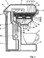
図1及び2において、参照番号1は、小さい泡のフォーム層を持つコーヒー抽出物を調製するための本発明によるコーヒーメーカーを指す。本発明の実施例の本説明において、飲料がブリューされるべき原材料はコーヒー粒である。しかし、他の物、例えばココア、ミルクパウダー、ドライストック、茶、ハーブ等も、飲料がブリューされることができる原材料として用いられることができることは明らかである。
【0010】
コーヒーメーカー1は、ハウジング2と、該ハウジング2にヒンジ4によってとめられると共に閉じ具10によって閉じた位置に固定されるカバー3とを持つ。ハウジング2は、前方に延在する部分を持ち、該部分の上面5は、コーヒーで満たされるべき1つ又は複数のカップ6を支持するための台(plateau)を形成する。ハウジング内に、水貯蔵部7が位置する。導管9が加熱チャンバ46を通じて延在し、該加熱チャンバ46内には電気加熱素子47が構成される。容器8から加圧された水を供給するために、ポンプ45が、導管9中でヒータ47の上流に構成される。
【0011】
スプリンクリングヘッド11がブリュー容器15のブリューチャンバ13の上壁12に組み込まれ、導管9の端を形成する。ブリュー容器15は、コーヒーブリューチャンバ13の下方境界を形成する底部14を持つ。底部14の支持スタブ16が上向きに突出し、これら突起16間の間隔は、液体飲料(本例ではコーヒー抽出物)が、挽かれたコーヒー粒又は粉末を含むパッド又はパウチ18から押し出されて底部14の放出口19に流れることを可能にする。底部14は、ブリュー容器ハウジング部20のリブ23によって支持され、該リブ23は、コーヒーメーカー1のメインハウジング2の一部によって支持される。動作状況においては、ブリューチャンバ13はシール21、35及び37によって水密に密閉されるので、ポンプ45によって発生される圧力には大幅な損失が発生せず、コーヒーが抽出されているときには、ポンプ45によって発生される全て又は実質的に全ての圧力がブリューチャンバ13に加えられる。コーヒー以外の飲料が調製されるべきであれば、パッドは他の材料、例えばココア粉末及び/又はミルク粉末を含んでもよく、これはフレーバーが付けられ及び/又は甘くされていてもよい。
【0012】
上方を向く面が底部14の一部を形成するノズル22は、コーヒー抽出物の通過のために利用可能な放出口19の断面を制限する。ノズル22は、パッド支持部15の一体部分であってもよい。
【0013】
放出口19は分散チャンバ36に流れ出て、該分散チャンバ36は、分注口(dispensing spouts)38を通じて延在する2つの分注チャネルと通じ、チャンバに放出されたコーヒー抽出物は、前記分注口38を介してプラットフォーム5上のカップ6に流入する。コーヒー抽出物上にフォームを形成するために、コーヒー抽出物は、バッファ容器36のバッファ量のコーヒー抽出物にノズル22から噴射される。
【0014】
底部14は、図1に示される第1の動作位置と図2に示される第2の動作位置との間で反転可能である。底部14が第1の動作位置にあるとき、ブリューチャンバ13は、1つのコーヒーパッド18を収容するための第1の容積を有する。
【0015】
底部14が第2の動作位置にあるとき、ブリューチャンバ13は、例えばより大きなコーヒーパッドの形で、又は、図2に示されるように、2杯のコーヒー若しくはより強い1杯のコーヒーを調製するための2つのコーヒーパッドの形で、より多くの粒子を収容するための第1の容積よりも大きい第2の容積を有する。本例によれば、ブリューチャンバのより大きな容積は、より少量の粒子に対して2倍多い量の粒子を受けるように適応され、このため、容積は、コーヒー粒及び/又は飲料を調製するための他の粒子を含むそれぞれ1つ及び2つのパッド又はパウチを収容するように適応される。
【0016】
ブリューチャンバ13の容積は、ブリューチャンバ13の底部14を取り外し、これを反転された方向で再取り付けすることにより単純な態様で変更されることができる。
【0017】
図1及び2に示される例によれば、底部14は、底部14が図1に示される方向にあるときには実質的にリブ23の上に載置される。図2に示される状況においては、底部14の横スリットは、リブ23の上部を受け、これは、底部がより低い位置に落ち込むことを許可し、このことは、これに応じて大きくされた容積のブリューチャンバ13を結果として生じる。
【0018】
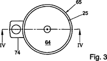
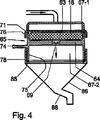
図3〜5は、代替の、現在最も好まれる本発明によるブリュー容器の実施例を示す。本例によれば、ブリュー容器65は、粒子パッド18を受けるための第1の穴67−1及び粒子パッド18を受けるための第2の穴67−2を有する。第2の穴67−2は、第1の穴67−1よりも大きな容積を持ち、底部64は、2つの穴67−1と67−2との間に位置する。本例によるブリュー容器は、容器65全体が取り外され反転された方向で取り付けられるということで、ブリューチャンバ63の容積を変化することを許可する。底部64が穴67−1及び67−2の境界を示す横壁75に一体的に接続されるので、容器は、別個の底部部材を持たず、更に、一般的には密封されなければならないことになる底部と壁との間の継ぎ目を持たない。ブリューの最中にコーヒーが通過するノズル69は、底部64の中心に位置する。
【0019】
容器65は、更に、該容器65を手で保持するためのハンドル74を有する。ハンドル74は、底部64に固定的に接続され、横に突出する。このようなハンドル74は、2つの互いに反転された動作位置間で容器65を操作するのに特に適している。なぜなら、両方の動作位置において、ハンドル74は、ユーザによって容易に到達されることができる同一方向に、容器65から突出することができるからである。
【0020】
更に、ハンドル74は、穴67−1及び67−2の境界を示す横壁75から突出するため、ハンドルはブリューチャンバ63の境界を通じて突出せず、ハンドルをこのような境界に対して密封する関連する必要性は回避される。
【0021】
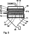
図3〜5に示される例によれば、飲料メーカーは、更に、容器固定具(fixture)76を有する。図4に示される動作状況においては、シール71が、容器65の上端と容器固定具76との間の継ぎ目を密封するように構成される。容器65の上端に加えて、その下端も、容器固定具76との密封係合のために適応されている。これは、容器65の図4において最も下の端が容器65の上端を形成している図5に見ることができる。
【0022】
飲料メーカーは更に飲料ファネル78を有する。図4に示される構成では、シール85が、容器65と飲料ファネル78との間の継ぎ目を密封する。図5に示される構成では、シール85は、容器65と容器固定具76との間の継ぎ目を密封する。ファネル形飲料導管86は、コーヒーを分注口88に導くために飲料ファネル78の下流に構成される。
【0023】
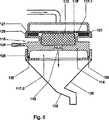
図6及び7は、本発明によるブリュー容器の更に他の代替実施例を示す。本例によれば、ブリュー容器115は、粒子パッド118'(又は適切なサイズの複数の粒子パッド)を受けるための第1の穴117−1と、ブリューチャンバの水の通過の方向に垂直な、パッド118'より大きい断面を持つ粒子パッド118を受けるための第2の穴117−2(又は適切なサイズの複数の粒子パッド)とを有する。
【0024】
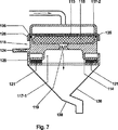
図1〜5に示される例において、動作時のブリューチャンバ13の底部14を反転させること又はその底部64を含む容器全体65を反転させることは、異なった量のコーヒー(又は飲料をブリューするための他の原料)を収容するためにブリューチャンバ13又は63の形状及び大きさを適応させる結果となった。一方で、穴117−1と117−2との間の違いは、その底部114を含む容器115を反転させることが、容積が実質的に同じままでブリューチャンバ113の形状を変化させる結果を生じる、ということである。これは、第2の穴117−2の形状に従う大きい断面を持つ比較的浅い形状と、第1の穴117−1の形状に従うより小さい断面を持つ比較的深い形状との間で動作時のブリューチャンバの形状を変化させることを許可する。
【0025】
ブリューチャンバ113の比較的浅い形状は、低から中程度の強さのコーヒーを調製するのに特に適しており、より小さい断面を持つ比較的深い形状は、強い、即ち非常に濃縮されたコーヒーを調製するのに特に適している。従って、この例によるブリュー容器115は、容器115を取り外してそれを反転された方向で取り付けることにより、ブリューされるべきコーヒーの所望の種類に応じて動作時のブリューチャンバの形状を変化させることを許可する。パッド118及び118'のコーヒー粒混合物は、例えば細かさ及び粒が挽かれたコーヒー豆の種類に関して互いに異なっていてもよく、それぞれの種類のコーヒーを調製するように特に適応されることができる。本発明によれば、ブリューチャンバ113の容積は、容器115が反転されても実質的に同じままであるが、例えば、或る種類のコーヒーを調製するための該コーヒーの所望の量が、他の種類のコーヒーを調製するための該コーヒーの所望の量よりも大きければ、穴117−1及び117−2の大きさ及び形状は、容器が反転されたら容積も変化するようにされてもよい。
【0026】
図6に示される動作状況において、シール121は、容器115の上端と容器固定具126との間の継ぎ目を密封するように構成される。図7に示されるように容器115が反転されたら、シール121は、容器115と飲料ファネル128との間の継ぎ目を密封する。容器115の上端と容器固定具126との間の継ぎ目は次にシール135によって密封され、該シールは、容器が図6に示される方向性にあるとき、容器115と表縁128との間の継ぎ目を密封する。
【0027】
ブリューの最中にコーヒーが通過するノズル119は、表縁128の下方部の中心に位置する。ブリューの最中に、ろ過されたコーヒーはノズル119からフォームユニット136に噴出し、このため、フォーム(「クレーマ(crema)」層が得られる。
【0028】
コーヒーは、スパウト138から分注される。好適には、フォームユニットの下方部に、ろ過されたコーヒーの一時的なプールを維持するための構成が設けられ、これにろ過物が噴出され、フォーム形成を向上させる。
【0029】
第1の穴117−1が上を向いており容器固定具126の方を向いていれば、スプリンクリングヘッドの水供給チャネルのうちの最も外の方のものはシール121によって閉じられる。図7に示される状況においては、大きな直径の第2の穴117−2がスプリンクリングヘッド111に面し、水供給チャネルのうちの最も外の方のものは閉じられない。容器115を反転させるために、該容器115は、該容器115から放射状に突出するグリップ124を備える。
【0030】
本発明の枠組内で、本発明を説明するために上記で説明された以外の多くの実施例が想到可能である。例えば、容器の又は少なくとも底部の少なくとも1つの方向で複数のブリューチャンバが設けられ、1つ又は複数の動作時のブリューチャンバの全容積が、容器全体又は底部が反転されると変化されることによって、飲料がブリューされるべき原料を受ける容積は可変であるようにすることができる。容器は、例えば、容器又は底部が第1の方向にあるときには、飲料をブリューするように機能する位置にある1つのブリューチャンバを持ち、容器又は底部が、第1の方向に対して反転された第2の方向にあるときには、飲料をブリューするように機能する位置にある2つのブリューチャンバを持つので、容器又は少なくとも底部が第1の方向から第2の方向に反転されると、前記少なくとも1つのブリューチャンバの動作時の容積が2倍される。
【図面の簡単な説明】
【0031】
【図1】 本発明によるブリュー容器の一例を有する本発明によるコーヒーメーカの一例の断面図である。
【図2】 ブリュー容器が、飲料がブリューされるべきより多くの粒子を収容するための代替の動作状況にある、図1のコーヒーメーカーの断面図である。
【図3】 本発明によるブリュー容器の第2の例の平面図である。
【図4】 本発明によるブリュー容器及び本発明による第2の飲料メーカーの隣接部分の図3の線IV−IVで取った横断面図である。
【図5】 ブリュー容器が、飲料がブリューされるべきより多くの粒子を収容するための代替の動作状況にある、図4の図である。
【図6】 本発明による第3のブリュー容器及び本発明による第3の飲料メーカーの隣接部分の横断面図である。
【図7】 ブリュー容器が、他の構成で飲料がブリューされるべき粒子を収容するための代替の動作状況にある、図6の図である。【Technical field】
[0001]
The invention relates to a brewing receptacle according to the opening part of claim 1 and to a set of parts, a foam unit and a beverage maker comprising such a brewing container. .
[Background]
[0002]
A brew container of the above kind is known from US Pat. No. 6,192,786. Since the side wall of the coffee container and the bottom formed by the filter plate define the volume of the container's brewing chamber, the portioning is substantially predetermined. According to this document, the container is intended to receive ground coffee. In order to adapt the volume of the brew chamber to different amounts of coffee grains to which the coffee is to be brewed, the filter plate can be moved stepwise to a predetermined position in the axial direction of the coffee container relative to the side wall of the coffee container. Configured as such, each of the above positions results in a different internal height of the brew chamber. For this purpose, a raising means in the form of a cam element is arranged to be rotatable in the coffee container and supports the projections of the filter plate at positions distributed on the circumference. The rotational movement of the cam element can adjust the position at which the filter plate is held by the cam element. The cam element is configured in the coffee container. As the diameter remains the same and the depth is reduced, the shape of the brew chamber changes with the volume of the brew chamber.
DISCLOSURE OF THE INVENTION
[Problems to be solved by the invention]
[0003]
The problem with such coffee containers is that the rotatable cam element in the coffee container forms an additional element and the structure designed to operate the cam element in the coffee element is relatively complex and therefore expensive. It is that.
[0004]
The object of the present invention is to provide a simpler solution that allows the beverage to be brewed to change the volume and / or shape of the brew chamber in which the particles to be brewed are housed in a particular shaped configuration.
[Means for Solving the Problems]
[0005]
According to the invention, this object is achieved by providing a brew container according to claim 1. Furthermore, according to the present invention, this object is the parts set according to claim 6, the foam unit according to
[0006]
Since the change in the total volume, shape or both volume and shape of the brew chamber during one or more operations is accomplished by inverting at least the bottom of the one or more chambers, the one or more No additional support is required to change the total volume of the brew chamber during operation . Furthermore, it is easy to change the total volume, shape or both volume and shape of one or more brew chambers used for brewing, and there are no complicated handling structures. This is because it is sufficient to provide that the bottom of one or more chambers be positioned in the proper orientation.
[0007]
Particularly advantageous embodiments of the invention are defined in the dependent claims.
BEST MODE FOR CARRYING OUT THE INVENTION
[0008]
Other features, advantages and details of the invention will be described with reference to the embodiments shown in the drawings.
[0009]
1 and 2, reference numeral 1 refers to a coffee maker according to the invention for preparing a coffee extract with a small foam foam layer. In the present description of the embodiments of the present invention, the raw material from which the beverage is to be brewed is coffee grains. However, it is clear that other things such as cocoa, milk powder, dry stock, tea, herbs, etc. can also be used as raw materials from which the beverage can be brewed.
[0010]
The coffee maker 1 has a housing 2 and a cover 3 which is fixed to the housing 2 by a hinge 4 and fixed in a closed position by a
[0011]
A
[0012]
A
[0013]
The outlet 19 flows into the
[0014]
[0015]
When the bottom 14 is in the second operating position, the
[0016]
The volume of the
[0017]
According to the example shown in FIGS. 1 and 2, the bottom 14 rests substantially on the
[0018]
3-5 show alternative, currently preferred brew container embodiments according to the present invention. According to this example, the
[0019]
The
[0020]
Furthermore, since the
[0021]
According to the example shown in FIGS. 3 to 5, the beverage manufacturer further has a container fixture 76. In the operating situation shown in FIG. 4, the
[0022]
The beverage manufacturer further has a
[0023]
Figures 6 and 7 show yet another alternative embodiment of a brew container according to the present invention. According to this example, the
[0024]
In the example shown in FIGS. 1-5, inverting the bottom 14 of the
[0025]
The relatively shallow shape of the
[0026]
In the operating situation shown in FIG. 6, the
[0027]
A
[0028]
Coffee is dispensed from the
[0029]
If the first hole 117-1 is facing upward and toward the
[0030]
Within the framework of the present invention, many embodiments other than those described above are possible to explain the present invention. For example, by providing a plurality of brew chambers in at least one direction of the container or at least at the bottom and changing the total volume of the brew chamber during one or more operations when the entire container or the bottom is inverted. The volume at which the beverage receives the ingredients to be brewed can be variable. The container has, for example, a brew chamber in a position that functions to brew the beverage when the container or bottom is in a first direction, and the container or bottom is inverted with respect to the first direction. When in the second direction, it has two brew chambers in a position that functions to brew the beverage, so that when the container or at least the bottom is inverted from the first direction to the second direction, the at least one The operating volume of one brew chamber is doubled.
[Brief description of the drawings]
[0031]
FIG. 1 is a cross-sectional view of an example of a coffee maker according to the present invention having an example of a brew container according to the present invention.
FIG. 2 is a cross-sectional view of the coffee maker of FIG. 1 with the brewing container in an alternative operating situation to contain more particles than the beverage is to be brewed.
FIG. 3 is a plan view of a second example of a brewing container according to the present invention.
4 is a cross-sectional view taken along line IV-IV in FIG. 3 of a brew container according to the present invention and an adjacent portion of a second beverage maker according to the present invention.
FIG. 5 is the view of FIG. 4 with the brew container in an alternative operating situation for containing more particles than the beverage is to be brewed.
FIG. 6 is a cross-sectional view of a third brewing container according to the present invention and an adjacent portion of a third beverage maker according to the present invention.
7 is a diagram of FIG. 6 with the brewing container in an alternative operating situation for containing particles to be brewed in other configurations.
Claims (9)
Applications Claiming Priority (2)
| Application Number | Priority Date | Filing Date | Title |
|---|---|---|---|
| EP03253319 | 2003-05-27 | ||
| PCT/IB2004/050729 WO2004105564A1 (en) | 2003-05-27 | 2004-05-18 | A brewing receptacle and a foam unit and a beverage maker comprising such a brewing receptacle |
Publications (3)
| Publication Number | Publication Date |
|---|---|
| JP2007503274A JP2007503274A (en) | 2007-02-22 |
| JP2007503274A5 JP2007503274A5 (en) | 2009-02-12 |
| JP4339358B2 true JP4339358B2 (en) | 2009-10-07 |
Family
ID=32892991
Family Applications (1)
| Application Number | Title | Priority Date | Filing Date |
|---|---|---|---|
| JP2006530877A Expired - Fee Related JP4339358B2 (en) | 2003-05-27 | 2004-05-18 | Brew container and foam unit and beverage manufacturer having such a brew container |
Country Status (9)
| Country | Link |
|---|---|
| US (1) | US7726233B2 (en) |
| EP (1) | EP1631176B1 (en) |
| JP (1) | JP4339358B2 (en) |
| CN (2) | CN100531633C (en) |
| AT (1) | ATE401813T1 (en) |
| DE (2) | DE602004015285D1 (en) |
| ES (1) | ES2309519T3 (en) |
| MX (1) | MXPA05012699A (en) |
| WO (1) | WO2004105564A1 (en) |
Families Citing this family (38)
| Publication number | Priority date | Publication date | Assignee | Title |
|---|---|---|---|---|
| NL1026068C2 (en) * | 2004-04-28 | 2005-10-31 | Sara Lee De Nv | Pad of the possibly flexible type and assembly of a holder and such a pad. |
| NL1028460C2 (en) * | 2005-03-04 | 2006-09-06 | Sara Lee De Nv | Device for preparing and dispensing beverages, whether or not at least partially foamed. |
| WO2006111890A1 (en) * | 2005-04-18 | 2006-10-26 | Koninklijke Philips Electronics N.V. | Coffee maker comprising means for generating a rotation in a flow of beverage |
| US20060266225A1 (en) * | 2005-05-25 | 2006-11-30 | Jamal Hammad | Single serve beverage maker with adjustable sealed showerhead |
| NL2000494C2 (en) * | 2006-03-21 | 2009-01-20 | Dong-Lei Wang | Foam device in a coffee machine. |
| US20100101427A1 (en) * | 2007-02-16 | 2010-04-29 | Koninklijke Philips Electronics N.V. | Controlling a liquid flow through heater |
| ITFI20070267A1 (en) * | 2007-11-28 | 2009-05-29 | Saeco Ipr Ltd | "INFUSION GROUP FOR THE PREPARATION OF DRINKS FROM SINGLE-DOSE PACKAGES AND MACHINE INCLUDING THE GROUP" |
| EP2098143A1 (en) | 2008-03-06 | 2009-09-09 | Koninklijke Philips Electronics N.V. | Set of articles which are suitable to be used in a process of making a beverage |
| DE102008021778A1 (en) * | 2008-04-30 | 2009-11-05 | Eugster/Frismag Ag | Process for the preparation and administration of milk froth or a beverage, device for carrying out the process, espresso machine with such a device and preparation vessel for use in such a device or espresso machine |
| CN101861113B (en) * | 2008-08-19 | 2015-09-23 | 雷沙奇·沙德利 | beverage dispenser |
| US9113747B2 (en) * | 2009-10-30 | 2015-08-25 | Adrian Rivera | Single and multi-cup coffee maker |
| EP2401945A1 (en) * | 2010-07-01 | 2012-01-04 | Nestec S.A. | A device for adapting a food capsule into a capsule holder |
| PT2430953E (en) * | 2010-09-17 | 2013-05-16 | Gruppo Cimbali Spa | Device for preparing espresso coffee by means of a measure of loose ground coffee or a measure of ground coffee contained in a capsule with predetermined breaking |
| EP3190067B1 (en) * | 2010-11-11 | 2018-07-11 | Nestec S.A. | Beverage production machine and system for the preparation of a beverage |
| CN102160750B (en) * | 2011-02-16 | 2013-04-24 | 广东新宝电器股份有限公司 | Instantaneous heating pot body |
| AU2013329853A1 (en) * | 2012-10-09 | 2015-04-23 | Nestec S.A. | Beverage machine |
| US9486104B2 (en) | 2013-03-05 | 2016-11-08 | B/E Aerospace, Inc. | Multi-purpose coffee maker pod holder |
| ITPN20130035A1 (en) | 2013-06-26 | 2014-12-27 | Osmap Asia Pacific Pte Ltd | PERFECT MACHINE FOR THE PREPARATION OF ONE OR A PLURALITY OF DRINKS |
| MX2016008538A (en) * | 2013-12-31 | 2016-09-26 | Koninklijke Philips Nv | Beverage machine. |
| US9439532B2 (en) | 2014-03-11 | 2016-09-13 | Starbucks Corporation | Beverage production machines with multi-chambered basket units |
| US9504348B2 (en) | 2014-03-11 | 2016-11-29 | Starbucks Corporation | Cartridge ejection systems and methods for single-serve beverage production machines |
| US20150257586A1 (en) * | 2014-03-11 | 2015-09-17 | Starbucks Corporation Dba Starbucks Coffee Company | Single-serve beverage production machine |
| CH709436A2 (en) * | 2014-03-21 | 2015-09-30 | Arco Design Gmbh | Procedures, herbal infusion container and preparation device for preparing an infusion beverage. |
| US10314320B2 (en) | 2015-03-20 | 2019-06-11 | Meltz, LLC | Systems for controlled liquid food or beverage product creation |
| US10111554B2 (en) | 2015-03-20 | 2018-10-30 | Meltz, LLC | Systems for and methods of controlled liquid food or beverage product creation |
| US10602874B2 (en) | 2015-06-16 | 2020-03-31 | Starbucks Corporation Dba Starbucks Coffee Company | Beverage preparation systems with brew chamber access mechanisms |
| US10342377B2 (en) | 2015-06-16 | 2019-07-09 | Starbucks Corporation | Beverage preparation systems with adaptable brew chambers |
| US9968217B2 (en) | 2015-06-16 | 2018-05-15 | Starbucks Corporation | Beverage preparation systems with brew chamber securing mechanisms |
| US10779675B2 (en) | 2015-12-07 | 2020-09-22 | Bunn-O-Matic Corporation | Brewer system, method and apparatus |
| DE102016212988A1 (en) * | 2016-07-15 | 2018-01-18 | Wmf Group Gmbh | Coffee machine for preparing pressure-extracted coffee with low particle content, method and use of the coffee machine |
| US11659953B2 (en) | 2016-12-13 | 2023-05-30 | Bunn-O-Matic Corporation | Bean to cup positive pressure brewer |
| DE102017202685A1 (en) | 2017-02-20 | 2018-08-23 | Wmf Group Gmbh | Filter capsule for post-filtration of coffee and use thereof |
| MX2019012834A (en) | 2017-04-27 | 2019-12-16 | Meltz Llc | Method for centrifugal extraction and apparatus suitable for carrying out this method. |
| EP3400914A1 (en) | 2017-05-08 | 2018-11-14 | Biotronik AG | Handle for a catheter and corresponding catheter |
| US11523703B2 (en) | 2018-01-23 | 2022-12-13 | Bunn-O-Matic Corporation | Brewer system, method and apparatus |
| US20200277130A1 (en) * | 2019-03-01 | 2020-09-03 | Alice Coffee, LLC | Disposable beverage bag and brewer adapter |
| KR102058732B1 (en) | 2019-06-05 | 2019-12-23 | 최자령 | Coffee Machine for Pod coffee |
| US11724849B2 (en) | 2019-06-07 | 2023-08-15 | Cometeer, Inc. | Packaging and method for single serve beverage product |
Family Cites Families (4)
| Publication number | Priority date | Publication date | Assignee | Title |
|---|---|---|---|---|
| US4149454A (en) * | 1978-03-30 | 1979-04-17 | General Electric Company | Coffeemaker basket and filter assembly |
| DE19832063C5 (en) | 1998-07-16 | 2004-10-21 | Maxs Ag | Espressobrühkopfeinheit |
| CA2325978A1 (en) * | 1999-11-16 | 2001-05-16 | Robert Hale | Beverage filter cartridge system |
| US7093530B2 (en) * | 2003-10-09 | 2006-08-22 | Applica Consumer Products, Inc. | Coffeemaker pod carrier |
-
2004
- 2004-05-18 JP JP2006530877A patent/JP4339358B2/en not_active Expired - Fee Related
- 2004-05-18 DE DE602004015285T patent/DE602004015285D1/en active Active
- 2004-05-18 US US10/557,682 patent/US7726233B2/en not_active Expired - Fee Related
- 2004-05-18 AT AT04733609T patent/ATE401813T1/en not_active IP Right Cessation
- 2004-05-18 CN CNB2004800148094A patent/CN100531633C/en not_active Expired - Fee Related
- 2004-05-18 ES ES04733609T patent/ES2309519T3/en active Active
- 2004-05-18 WO PCT/IB2004/050729 patent/WO2004105564A1/en active IP Right Grant
- 2004-05-18 MX MXPA05012699A patent/MXPA05012699A/en active IP Right Grant
- 2004-05-18 EP EP04733609A patent/EP1631176B1/en not_active Not-in-force
- 2004-05-24 CN CNU200420067876XU patent/CN2768621Y/en not_active Expired - Lifetime
- 2004-05-27 DE DE202004008637U patent/DE202004008637U1/en not_active Expired - Lifetime
Also Published As
| Publication number | Publication date |
|---|---|
| EP1631176A1 (en) | 2006-03-08 |
| CN1794937A (en) | 2006-06-28 |
| CN2768621Y (en) | 2006-04-05 |
| MXPA05012699A (en) | 2006-02-22 |
| DE202004008637U1 (en) | 2004-08-19 |
| ES2309519T3 (en) | 2008-12-16 |
| EP1631176B1 (en) | 2008-07-23 |
| US20070039476A1 (en) | 2007-02-22 |
| JP2007503274A (en) | 2007-02-22 |
| ATE401813T1 (en) | 2008-08-15 |
| US7726233B2 (en) | 2010-06-01 |
| CN100531633C (en) | 2009-08-26 |
| WO2004105564A1 (en) | 2004-12-09 |
| DE602004015285D1 (en) | 2008-09-04 |
Similar Documents
| Publication | Publication Date | Title |
|---|---|---|
| JP4339358B2 (en) | Brew container and foam unit and beverage manufacturer having such a brew container | |
| JP2007503274A5 (en) | ||
| EP1699329B1 (en) | A beverage maker incorporating multiple beverage collection chambers | |
| CA2496416C (en) | Form-retaining pad for preparing a beverage suitable for consumption | |
| ES2290735T3 (en) | DRINK PRODUCTION MACHINE WITH ADJUSTABLE DRINK PREPARATION CHAMBER. | |
| EP1624780B1 (en) | Coffee brewer | |
| US20140072684A1 (en) | French press beverage maker | |
| EP1398279A2 (en) | Form-retaining pad for preparing a beverage suitable for consumption | |
| US20190000262A1 (en) | Filter member for brewing coffee, apparatus and products comprising such filter, methods of making and using such filter, product and apparatus, and coffee brewing methods | |
| US20100239728A1 (en) | Method for activating and emptying beverage preparation holders | |
| US20070071869A1 (en) | Preparation of a beverage suitable for consumption | |
| JP2013544172A (en) | Beverage preparation device with droplet collector | |
| MXPA03002703A (en) | Coffee maker. | |
| RU2489956C2 (en) | Set of items suitable for usage in process of beverage preparation | |
| HUE031099T2 (en) | Capsule for preparing a beverage or liquid food and system using brewing centrifugal force | |
| US20090133584A1 (en) | Exchangeable holder for use in an apparatus for preparing a beverage suitable for consumption | |
| AU2008283726A1 (en) | Support with a double resting surface for cups and other containers in machines for the production of beverages | |
| WO2005063089A1 (en) | A coffee maker having a filter support incorporating a sieve | |
| US20140182458A1 (en) | Microwave Beverage Cartridge Holder | |
| CN111770710A (en) | Beverage machine with partially closed dispensing face | |
| CN111801035B (en) | Beverage machine with partially open dispensing face | |
| JP2022519349A (en) | Beverage distribution system with receptor placement and deployment of beverages and beverage preparation fluids | |
| JPH0464686B2 (en) |
Legal Events
| Date | Code | Title | Description |
|---|---|---|---|
| A621 | Written request for application examination |
Free format text: JAPANESE INTERMEDIATE CODE: A621 Effective date: 20070518 |
|
| A521 | Request for written amendment filed |
Free format text: JAPANESE INTERMEDIATE CODE: A523 Effective date: 20070529 |
|
| A131 | Notification of reasons for refusal |
Free format text: JAPANESE INTERMEDIATE CODE: A131 Effective date: 20080617 |
|
| A601 | Written request for extension of time |
Free format text: JAPANESE INTERMEDIATE CODE: A601 Effective date: 20080916 |
|
| A602 | Written permission of extension of time |
Free format text: JAPANESE INTERMEDIATE CODE: A602 Effective date: 20080924 |
|
| A524 | Written submission of copy of amendment under article 19 pct |
Free format text: JAPANESE INTERMEDIATE CODE: A524 Effective date: 20081211 |
|
| TRDD | Decision of grant or rejection written | ||
| A01 | Written decision to grant a patent or to grant a registration (utility model) |
Free format text: JAPANESE INTERMEDIATE CODE: A01 Effective date: 20090602 |
|
| A01 | Written decision to grant a patent or to grant a registration (utility model) |
Free format text: JAPANESE INTERMEDIATE CODE: A01 |
|
| A61 | First payment of annual fees (during grant procedure) |
Free format text: JAPANESE INTERMEDIATE CODE: A61 Effective date: 20090701 |
|
| R150 | Certificate of patent or registration of utility model |
Ref document number: 4339358 Country of ref document: JP Free format text: JAPANESE INTERMEDIATE CODE: R150 Free format text: JAPANESE INTERMEDIATE CODE: R150 |
|
| FPAY | Renewal fee payment (event date is renewal date of database) |
Free format text: PAYMENT UNTIL: 20120710 Year of fee payment: 3 |
|
| FPAY | Renewal fee payment (event date is renewal date of database) |
Free format text: PAYMENT UNTIL: 20130710 Year of fee payment: 4 |
|
| R250 | Receipt of annual fees |
Free format text: JAPANESE INTERMEDIATE CODE: R250 |
|
| R250 | Receipt of annual fees |
Free format text: JAPANESE INTERMEDIATE CODE: R250 |
|
| R250 | Receipt of annual fees |
Free format text: JAPANESE INTERMEDIATE CODE: R250 |
|
| R250 | Receipt of annual fees |
Free format text: JAPANESE INTERMEDIATE CODE: R250 |
|
| R250 | Receipt of annual fees |
Free format text: JAPANESE INTERMEDIATE CODE: R250 |
|
| R250 | Receipt of annual fees |
Free format text: JAPANESE INTERMEDIATE CODE: R250 |
|
| R250 | Receipt of annual fees |
Free format text: JAPANESE INTERMEDIATE CODE: R250 |
|
| R250 | Receipt of annual fees |
Free format text: JAPANESE INTERMEDIATE CODE: R250 |
|
| LAPS | Cancellation because of no payment of annual fees |