EP1631176B1 - A brewing receptacle and a foam unit and a beverage maker comprising such a brewing receptacle - Google Patents
A brewing receptacle and a foam unit and a beverage maker comprising such a brewing receptacle Download PDFInfo
- Publication number
- EP1631176B1 EP1631176B1 EP04733609A EP04733609A EP1631176B1 EP 1631176 B1 EP1631176 B1 EP 1631176B1 EP 04733609 A EP04733609 A EP 04733609A EP 04733609 A EP04733609 A EP 04733609A EP 1631176 B1 EP1631176 B1 EP 1631176B1
- Authority
- EP
- European Patent Office
- Prior art keywords
- receptacle
- brewing
- shape
- volume
- particles
- Prior art date
- Legal status (The legal status is an assumption and is not a legal conclusion. Google has not performed a legal analysis and makes no representation as to the accuracy of the status listed.)
- Expired - Lifetime
Links
- 235000013361 beverage Nutrition 0.000 title claims abstract description 35
- 239000006260 foam Substances 0.000 title claims description 11
- 239000002245 particle Substances 0.000 claims abstract description 27
- XLYOFNOQVPJJNP-UHFFFAOYSA-N water Substances O XLYOFNOQVPJJNP-UHFFFAOYSA-N 0.000 claims abstract description 9
- 239000007788 liquid Substances 0.000 claims abstract description 6
- 238000007599 discharging Methods 0.000 claims abstract 2
- 238000010438 heat treatment Methods 0.000 claims description 2
- 239000008187 granular material Substances 0.000 description 6
- 239000000047 product Substances 0.000 description 5
- 239000000843 powder Substances 0.000 description 4
- 239000000706 filtrate Substances 0.000 description 3
- 238000007789 sealing Methods 0.000 description 3
- 244000299461 Theobroma cacao Species 0.000 description 2
- 235000009470 Theobroma cacao Nutrition 0.000 description 2
- 235000013336 milk Nutrition 0.000 description 2
- 239000008267 milk Substances 0.000 description 2
- 210000004080 milk Anatomy 0.000 description 2
- 241000533293 Sesbania emerus Species 0.000 description 1
- 244000269722 Thea sinensis Species 0.000 description 1
- 230000015572 biosynthetic process Effects 0.000 description 1
- 230000001419 dependent effect Effects 0.000 description 1
- 230000000694 effects Effects 0.000 description 1
- 238000005485 electric heating Methods 0.000 description 1
- 230000003028 elevating effect Effects 0.000 description 1
- 230000002708 enhancing effect Effects 0.000 description 1
- 235000008216 herbs Nutrition 0.000 description 1
- 239000000203 mixture Substances 0.000 description 1
- 239000000126 substance Substances 0.000 description 1
- 238000011144 upstream manufacturing Methods 0.000 description 1
Images


Classifications
-
- A—HUMAN NECESSITIES
- A61—MEDICAL OR VETERINARY SCIENCE; HYGIENE
- A61B—DIAGNOSIS; SURGERY; IDENTIFICATION
- A61B1/00—Instruments for performing medical examinations of the interior of cavities or tubes of the body by visual or photographical inspection, e.g. endoscopes; Illuminating arrangements therefor
- A61B1/012—Instruments for performing medical examinations of the interior of cavities or tubes of the body by visual or photographical inspection, e.g. endoscopes; Illuminating arrangements therefor characterised by internal passages or accessories therefor
- A61B1/018—Instruments for performing medical examinations of the interior of cavities or tubes of the body by visual or photographical inspection, e.g. endoscopes; Illuminating arrangements therefor characterised by internal passages or accessories therefor for receiving instruments
-
- A—HUMAN NECESSITIES
- A47—FURNITURE; DOMESTIC ARTICLES OR APPLIANCES; COFFEE MILLS; SPICE MILLS; SUCTION CLEANERS IN GENERAL
- A47J—KITCHEN EQUIPMENT; COFFEE MILLS; SPICE MILLS; APPARATUS FOR MAKING BEVERAGES
- A47J31/00—Apparatus for making beverages
- A47J31/06—Filters or strainers for coffee or tea makers ; Holders therefor
- A47J31/0647—Filters or strainers for coffee or tea makers ; Holders therefor with means to adjust the brewing chamber volume to accommodate different quantities of brewing material
-
- A—HUMAN NECESSITIES
- A47—FURNITURE; DOMESTIC ARTICLES OR APPLIANCES; COFFEE MILLS; SPICE MILLS; SUCTION CLEANERS IN GENERAL
- A47J—KITCHEN EQUIPMENT; COFFEE MILLS; SPICE MILLS; APPARATUS FOR MAKING BEVERAGES
- A47J31/00—Apparatus for making beverages
- A47J31/06—Filters or strainers for coffee or tea makers ; Holders therefor
- A47J31/0657—Filters or strainers for coffee or tea makers ; Holders therefor for brewing coffee under pressure, e.g. for espresso machines
- A47J31/0668—Filters or strainers for coffee or tea makers ; Holders therefor for brewing coffee under pressure, e.g. for espresso machines specially adapted for cartridges
- A47J31/0678—Means to separate the cartridge from the bottom of the brewing chamber, e.g. grooves or protrusions
-
- A—HUMAN NECESSITIES
- A47—FURNITURE; DOMESTIC ARTICLES OR APPLIANCES; COFFEE MILLS; SPICE MILLS; SUCTION CLEANERS IN GENERAL
- A47J—KITCHEN EQUIPMENT; COFFEE MILLS; SPICE MILLS; APPARATUS FOR MAKING BEVERAGES
- A47J31/00—Apparatus for making beverages
- A47J31/06—Filters or strainers for coffee or tea makers ; Holders therefor
- A47J31/0657—Filters or strainers for coffee or tea makers ; Holders therefor for brewing coffee under pressure, e.g. for espresso machines
- A47J31/0684—Sealing means for sealing the filter holder to the brewing head
-
- A—HUMAN NECESSITIES
- A61—MEDICAL OR VETERINARY SCIENCE; HYGIENE
- A61B—DIAGNOSIS; SURGERY; IDENTIFICATION
- A61B1/00—Instruments for performing medical examinations of the interior of cavities or tubes of the body by visual or photographical inspection, e.g. endoscopes; Illuminating arrangements therefor
- A61B1/005—Flexible endoscopes
- A61B1/0051—Flexible endoscopes with controlled bending of insertion part
Definitions
- the invention relates to a brewing receptacle according to the introductory portion of claim 1 as well as to a set of parts, to a foam unit, and to a beverage maker comprising such a brewing receptacle.
- a brewing receptacle of the above type is known from United States patent 6,192,786 .
- a lateral wall of the coffee receptacle and a bottom formed by a filter plate define the volume of the brewing chamber of the receptacle, so that portioning is substantially predetermined.
- the receptacle is intended for receiving ground coffee.
- the filter plate is arranged such that it is displaceable stepwise relative to the lateral wall of the coffee receptacle into predetermined positions in axial direction of the coffee receptacle, each position resulting in a different internal height of the brewing chamber.
- an elevating means in the form of a cam element is rotatably arranged in the coffee receptacle and supports projections of the filter plate in circumferentially distributed positions.
- a rotational movement of the cam element is capable of adjusting the position in which the filter plate is held by the cam element.
- the cam element is arranged in the coffee receptacle. With the volume of the brewing chamber, also the shape of the brewing chamber is changed, since the depth is reduced while the diameter remains the same.
- a problem of such a coffee receptacle is that the rotatable cam element in the coffee receptacle forms an additional element, and that the structure designed to operate the cam element inside the coffee receptacle is relatively complicated and therefore costly.
- this object is achieved by providing a brewing receptacle according to claim 1. Furthermore, according to the invention, this object can be achieved by providing a set of parts according to claim 6, a foam unit according to claim 7, or a beverage maker according to claim 8, which each comprise such a brewing receptacle.
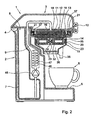
- reference numeral I designates a coffee maker according to the invention for preparing coffee extract having a small-bubble foam layer.
- the product from which a beverage is to be brewed is a coffee granulate. It will be clear, however, that other products such as cocoa, milk powder, dried stock, tea, herbs, etc. may also be used as products from which beverages can be brewed.
- the coffee maker 1 has a housing 2 and a cover 3 hinged to the housing 2 by a hinge 4 and fixed in closed position by a closure 10.
- the housing 2 has a forwardly extending portion of which a top surface 5 forms a plateau for supporting one or more cups 6 to be filled with coffee.
- a water reservoir 7 is located within the housing.
- a conduit 9 extends through a heating chamber 46 in which an electric heating element 47 is arranged.
- a pump 45 is arranged in the conduit 9 upstream of the heater 47.
- a sprinkling head 11 is integrated in a top wall 12 of a brewing chamber 13 in a brewing receptacle 15 and forms the end of the conduit 9.
- the brewing receptacle 15 has a bottom 14 forming the lower boundary of the coffee brewing chamber 13.
- Support stubs 16 of the bottom 14 project upwardly and interspaces between these projections 16 allow beverage liquid - coffee extract in the present example - pressed out of a pad or pouch 18 containing a ground coffee granulate or powder to flow to a discharge opening 19 in the bottom 14.
- the bottom 14 is supported by ribs 23 of a brewing receptacle housing part 20, which in turn is supported by portions of the main housing 2 of the coffee maker 1.
- the brewing chamber 13 In the operating condition, the brewing chamber 13 is watertightly sealed by seals 21, 35, and 37 so that no significant loss of pressure generated by the pump 45 occurs and all or virtually all pressure generated by the pump 45 is applied to the brewing chamber 13 when coffee is being extracted.
- the pad may contain other substances, for example cocoa powder and/or milk powder, which may be flavored and/or sweetened.
- a nozzle 22 of which an upwardly oriented face forms part of the bottom 14 restricts the cross-section of the discharge opening 19 available for the passage of coffee extract.
- the nozzle 22 may also be an integral part of the pad support 15.
- the discharge opening 19 debouches into a dispersing chamber 36 that communicates with two dispensing channels extending through dispensing spouts 38 via which coffee extract dispersed in the chamber can flow into the cups 6 on the platform 5.
- the coffee extract is jetted from the nozzle 22 into a buffer quantity of coffee extract in the buffer reservoir 36.
- the bottom 14 is invertible between a first operative position shown in Fig. 1 and a second operative position shown in Fig. 2 .
- the brewing chamber 13 has a first volume for accommodating one coffee pad 18.
- the brewing chamber 13 has a second volume larger than first volume, for accommodating more particles, for instance in the form of a larger coffee pad or, as shown in Fig. 2 , two coffee pads for preparing two cups of coffee or a stronger cup of coffee.
- the larger volume of the brewing chamber is adapted for receiving an amount of particles that is twice as large as the smaller amount of particles, so that the volumes are adapted for accommodating one and two pads or pouches, respectively, containing coffee granulate and/or other particles for preparing beverages.
- the volume of the brewing chamber 13 can be changed in a simple manner by removing the bottom 14 of the brewing chamber 13 and remounting it in an inverted orientation.
- the bottom 14 rests essentially on top of the ribs 23 when the bottom 14 is in the orientation shown in Fig. 1 .
- lateral slits in the bottom 14 receive upper portions of the ribs 23, which allows the bottom to sink to a lower position, which results in an accordingly enlarged volume of the brewing chamber 13.
- Figs. 3 to 5 show an alternative, presently most preferred embodiment of a brewing receptacle according to the invention.
- the brewing receptacle 65 comprises a first hollow 67-1 for receiving the particle pads 18 and a second hollow 67-2 for receiving the particles pads 18.
- the second hollow 67-2 has a larger volume than the first hollow 67-1, and the bottom 64 is located between the two hollows 67-1 and 67-2.
- the brewing receptacle according to this example allows changing of the volume of the brewing chamber 63 in that the whole receptacle 65 is dismounted and remounted in an inverted orientation.
- the receptacle Since the bottom 64 is integrally connected to sidewalls 75 bounding the hollows 67-1 and 67-2, the receptacle has no separate bottom member and no seams between the bottom and the walls that would generally need to be sealed.
- the nozzle 69 through which coffee passes during brewing is located centrally in the bottom 64.
- the receptacle 65 further comprises a handle 74 for manually holding the receptacle 65.
- the handle 74 is fixedly connected to and projects laterally from the bottom 64.
- Such a handle 74 is particularly suitable for manipulating the receptacle 65 between the two mutually inverted operating positions, because in both operating positions, the handle 74 can project from the receptacle 65 in the same direction where it can be easily reached by the user.
- the handle 74 projects from a side wall 75 bounding the hollows 67-1 and 67-2, so that the handle does not project through a boundary of the brewing chamber 63, and an associated need to seal the handle against such a boundary is avoided.
- the beverage maker further comprises a receptacle fixture 76.
- a seal 71 is arranged for sealing a seam between an upper edge of the receptacle 65 and the receptacle fixture 76.
- its lower end is also adapted for sealing engagement with the receptacle fixture 76, as can be seen in Fig. 5 , where the end of the receptacle 65 that is lowermost in Fig. 4 now forms the upper end of the receptacle 65.
- the beverage maker further comprises a beverage funnel 78.
- a seal 85 seals a seam between the receptacle 65 and the beverage funnel 78.
- the seal 85 seals a seam between the receptacle 65 and the receptacle fixture 76.
- a funnel-shaped beverage conduit 86 is arranged downstream of the beverage funnel 78 for guiding coffee to dispensing spouts 88.
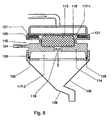
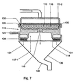
- Figs. 6 and 7 show yet another alternative embodiment of a brewing receptacle according to the invention.
- the brewing receptacle 115 comprises a first hollow 117-1 for receiving a particle pad 118' (or a plurality of particle pads of suitable size) and a second hollow 117-2 for receiving a particle pad 118 (or a plurality of particle pads of suitable size) having a larger cross-section transverse to the direction of passage of the water through the brewing chamber than the pad 118'.
- inverting the bottom 14 of the operational brewing chamber 13 or inverting the whole receptacle 65 including its bottom 64 resulted in adapting the shape and the size of the brewing chamber 13 or 63 for accommodating different amounts of coffee (or other product for brewing a beverage)
- the differences between the hollows 117-1 and 117-2 are such that inverting the receptacle 115 including its bottom 114 results in changing the shape of the brewing chamber 113 while the volume remains essentially the same.
- the relatively shallow shape of the brewing chamber 113 is particularly suitable for preparing coffee of low to medium strength and the relatively deep shape having a smaller cross-sectional surface is particularly suitable for preparing strong, i.e. very concentrated coffee.
- the brewing receptacle 115 allows changing the shape of the operational brewing chamber in accordance with the desired type of coffee to be brewed by dismounting the receptacle 115 and remounting it in an inverted orientation.
- the coffee granulate mixtures in the pads 118 and 118' may be different from each other, for instance with respect to fineness and type of coffee beans from which the granulate has been ground, and specifically adapted for preparing the respective types of coffee.
- the volume of the brewing chamber 113 remains essentially the same if the receptacle 115 is inverted, it may be provided that the size and shapes of the hollows 117-1 and 117-2 are such that the volume also changes if the receptacle is inverted, for instance if the preferred amount of coffee for preparing one type of coffee is larger than the preferred amount of coffee for preparing another type of coffee.
- a seal 121 is arranged for sealing off a seam between an upper edge of the receptacle 115 and the receptacle fixture 126. If the receptacle 115 is inverted, as is shown in Fig. 7 , the seal 121 seals off a seam between the receptacle 115 and a beverage funnel 128. The seam between an upper edge of the receptacle 115 and the receptacle fixture 126 is then sealed by a seal 135, which seal seals off a seam between the receptacle 115 and a bezel 128 when the receptacle is in the orientation shown in Fig. 6 .
- the nozzle 119 through which coffee passes during brewing is located centrally in a lower portion of the bezel 128.
- the coffee filtrate is jetted from the nozzle 119 into a foam unit 136 so that coffee with a foam ("crema") layer is obtained.
- the coffee is dispensed from a spout 138.
- Preferably arrangements are provided to maintain a temporary pool of coffee filtrate in a lower portion of the foam unit, into which the filtrate is jetted for enhancing foam formation.
- first hollow 117-1 is facing upwards and towards the receptacle fixture 126, the outermost ones of the water supply channels in the sprinkling head are closed off by the seal 121.
- second hollow 117-2 faces the sprinkling head 111, the outermost ones of the water supply channels are not closed off.
- the receptacle 115 it is provided with a grip 124 radially projecting from the receptacle 115.
- the volume for receiving the product from which a beverage is to be brewed is variable by providing that a multiple brewing chamber is provided in at least one orientation of the receptacle or at least of the bottom, and the total volume of the operational brewing chamber or chambers is changed when the bottom or the whole receptacle is inverted.
- the receptacle may, for example, have one brewing chamber that is in a position operative for brewing a beverage when the receptacle or the bottom is in a first orientation and have two brewing chambers that are in a position operative for brewing a beverage when the receptacle or the bottom is in a second orientation inverted relative to the first orientation, so that the operative volume of the at least one brewing chamber is doubled if the receptacle or at least the bottom is inverted from the first orientation to the second orientation.
Landscapes
- Health & Medical Sciences (AREA)
- Life Sciences & Earth Sciences (AREA)
- Engineering & Computer Science (AREA)
- Surgery (AREA)
- Food Science & Technology (AREA)
- Biomedical Technology (AREA)
- Animal Behavior & Ethology (AREA)
- Radiology & Medical Imaging (AREA)
- Optics & Photonics (AREA)
- Nuclear Medicine, Radiotherapy & Molecular Imaging (AREA)
- Physics & Mathematics (AREA)
- Heart & Thoracic Surgery (AREA)
- Medical Informatics (AREA)
- Molecular Biology (AREA)
- Pathology (AREA)
- General Health & Medical Sciences (AREA)
- Public Health (AREA)
- Veterinary Medicine (AREA)
- Biophysics (AREA)
- Apparatus For Making Beverages (AREA)
- Alcoholic Beverages (AREA)
- Distillation Of Fermentation Liquor, Processing Of Alcohols, Vinegar And Beer (AREA)
Abstract
Description
- The invention relates to a brewing receptacle according to the introductory portion of
claim 1 as well as to a set of parts, to a foam unit, and to a beverage maker comprising such a brewing receptacle. - A brewing receptacle of the above type is known from United States patent
6,192,786 . A lateral wall of the coffee receptacle and a bottom formed by a filter plate define the volume of the brewing chamber of the receptacle, so that portioning is substantially predetermined. According to this document, the receptacle is intended for receiving ground coffee. For adapting the volume of the brewing chamber to different amounts of coffee granulate from which coffee is to be brewed, the filter plate is arranged such that it is displaceable stepwise relative to the lateral wall of the coffee receptacle into predetermined positions in axial direction of the coffee receptacle, each position resulting in a different internal height of the brewing chamber. To this end, an elevating means in the form of a cam element is rotatably arranged in the coffee receptacle and supports projections of the filter plate in circumferentially distributed positions. A rotational movement of the cam element is capable of adjusting the position in which the filter plate is held by the cam element. The cam element is arranged in the coffee receptacle. With the volume of the brewing chamber, also the shape of the brewing chamber is changed, since the depth is reduced while the diameter remains the same. - A problem of such a coffee receptacle is that the rotatable cam element in the coffee receptacle forms an additional element, and that the structure designed to operate the cam element inside the coffee receptacle is relatively complicated and therefore costly.
- It is an object of the present invention to provide a simpler solution that allows to change the volume and/or the shape of the brewing chamber in which particles from which a beverage is to be brewed are accommodated in a configuration of a particular shape.
- According to the present invention, this object is achieved by providing a brewing receptacle according to
claim 1. Furthermore, according to the invention, this object can be achieved by providing a set of parts according toclaim 6, a foam unit according toclaim 7, or a beverage maker according toclaim 8, which each comprise such a brewing receptacle. - Since the change in total volume, shape, or both volume and shape of the operational brewing chamber or chambers is achieved by inverting at least the bottom of the brewing chamber or chambers, no additional support member is required for changing the overall volume of the operational brewing chamber or brewing chambers. Furthermore, changing the total volume, shape, or both volume and shape of the brewing chamber or chambers that are operational for brewing is easy, also in the absence of a complicated operating structure, because it is sufficient to provide that the bottom of the brewing chamber or chambers is arranged in the proper orientation.
- Particularly advantageous embodiments of the invention are set forth in the dependent claims.
- Further features, effects and details of the invention are described with reference to the embodiments shown in the drawings.
-
Fig. 1 is a cross-sectional view of an example of a coffee maker according to the present invention comprising an example of a brewing receptacle according to the present invention; -
Fig. 2 is a cross-sectional view of the coffee maker ofFig. 1 , but with the brewing receptacle in an alternative operating condition for accommodating more particles from which a beverage is to be brewed; -
Fig. 3 is a top plan view of a second example of a brewing receptacle according to the invention; -
Fig. 4 is a lateral cross-sectional view taken on the line IV-IV inFig. 3 of a brewing receptacle and of adjacent parts of a second beverage maker according to the invention; -
Fig. 5 is a view according toFig. 4 , but with the brewing receptacle in an alternative operating condition for accommodating more particles from which a beverage is to be brewed; -
Fig. 6 is a lateral cross-sectional view of a third brewing receptacle according to the invention and of adjacent parts of a third beverage maker according to the invention; and -
Fig. 7 is a view according toFig. 6 , but with the brewing receptacle in an alternative operating condition for accommodating the particles from which a beverage is to be brewed in another configuration. - In
Figs. 1 and2 , reference numeral I designates a coffee maker according to the invention for preparing coffee extract having a small-bubble foam layer. In the present description of examples of embodiments of the invention, the product from which a beverage is to be brewed is a coffee granulate. It will be clear, however, that other products such as cocoa, milk powder, dried stock, tea, herbs, etc. may also be used as products from which beverages can be brewed. - The
coffee maker 1 has ahousing 2 and acover 3 hinged to thehousing 2 by a hinge 4 and fixed in closed position by aclosure 10. Thehousing 2 has a forwardly extending portion of which atop surface 5 forms a plateau for supporting one ormore cups 6 to be filled with coffee. Within the housing, awater reservoir 7 is located. Aconduit 9 extends through aheating chamber 46 in which anelectric heating element 47 is arranged. For providing a pressurized supply of water from thereservoir 8, apump 45 is arranged in theconduit 9 upstream of theheater 47. - A
sprinkling head 11 is integrated in atop wall 12 of abrewing chamber 13 in abrewing receptacle 15 and forms the end of theconduit 9. Thebrewing receptacle 15 has abottom 14 forming the lower boundary of thecoffee brewing chamber 13.Support stubs 16 of thebottom 14 project upwardly and interspaces between theseprojections 16 allow beverage liquid - coffee extract in the present example - pressed out of a pad orpouch 18 containing a ground coffee granulate or powder to flow to a discharge opening 19 in thebottom 14. Thebottom 14 is supported byribs 23 of a brewingreceptacle housing part 20, which in turn is supported by portions of themain housing 2 of thecoffee maker 1. In the operating condition, thebrewing chamber 13 is watertightly sealed byseals pump 45 occurs and all or virtually all pressure generated by thepump 45 is applied to thebrewing chamber 13 when coffee is being extracted. If other drinks than coffee are to be prepared, the pad may contain other substances, for example cocoa powder and/or milk powder, which may be flavored and/or sweetened. - A
nozzle 22 of which an upwardly oriented face forms part of thebottom 14 restricts the cross-section of the discharge opening 19 available for the passage of coffee extract. Thenozzle 22 may also be an integral part of thepad support 15. - The discharge opening 19 debouches into a dispersing
chamber 36 that communicates with two dispensing channels extending through dispensingspouts 38 via which coffee extract dispersed in the chamber can flow into thecups 6 on theplatform 5. For forming foam on a coffee extract, the coffee extract is jetted from thenozzle 22 into a buffer quantity of coffee extract in thebuffer reservoir 36. - The
bottom 14 is invertible between a first operative position shown inFig. 1 and a second operative position shown inFig. 2 . When thebottom 14 is in the first operative position, thebrewing chamber 13 has a first volume for accommodating onecoffee pad 18. When thebottom 14 is in the second operative position, thebrewing chamber 13 has a second volume larger than first volume, for accommodating more particles, for instance in the form of a larger coffee pad or, as shown inFig. 2 , two coffee pads for preparing two cups of coffee or a stronger cup of coffee. According to the present example, the larger volume of the brewing chamber is adapted for receiving an amount of particles that is twice as large as the smaller amount of particles, so that the volumes are adapted for accommodating one and two pads or pouches, respectively, containing coffee granulate and/or other particles for preparing beverages. - The volume of the
brewing chamber 13 can be changed in a simple manner by removing thebottom 14 of thebrewing chamber 13 and remounting it in an inverted orientation. - According to the example shown in
Figs. 1 and2 , thebottom 14 rests essentially on top of theribs 23 when thebottom 14 is in the orientation shown inFig. 1 . In the situation shown inFig. 2 , lateral slits in thebottom 14 receive upper portions of theribs 23, which allows the bottom to sink to a lower position, which results in an accordingly enlarged volume of thebrewing chamber 13. -
Figs. 3 to 5 show an alternative, presently most preferred embodiment of a brewing receptacle according to the invention. According to this example, thebrewing receptacle 65 comprises a first hollow 67-1 for receiving theparticle pads 18 and a second hollow 67-2 for receiving theparticles pads 18. The second hollow 67-2 has a larger volume than the first hollow 67-1, and thebottom 64 is located between the two hollows 67-1 and 67-2. The brewing receptacle according to this example allows changing of the volume of thebrewing chamber 63 in that thewhole receptacle 65 is dismounted and remounted in an inverted orientation. Since thebottom 64 is integrally connected tosidewalls 75 bounding the hollows 67-1 and 67-2, the receptacle has no separate bottom member and no seams between the bottom and the walls that would generally need to be sealed. Thenozzle 69 through which coffee passes during brewing is located centrally in thebottom 64. - The
receptacle 65 further comprises ahandle 74 for manually holding thereceptacle 65. Thehandle 74 is fixedly connected to and projects laterally from thebottom 64. Such ahandle 74 is particularly suitable for manipulating thereceptacle 65 between the two mutually inverted operating positions, because in both operating positions, thehandle 74 can project from thereceptacle 65 in the same direction where it can be easily reached by the user. - Furthermore, the
handle 74 projects from aside wall 75 bounding the hollows 67-1 and 67-2, so that the handle does not project through a boundary of thebrewing chamber 63, and an associated need to seal the handle against such a boundary is avoided. - According to the example shown in
Figs. 3 to 5 , the beverage maker further comprises areceptacle fixture 76. In the operative condition shown inFig. 4 , aseal 71 is arranged for sealing a seam between an upper edge of thereceptacle 65 and thereceptacle fixture 76. In addition to the upper end of thereceptacle 65, its lower end is also adapted for sealing engagement with thereceptacle fixture 76, as can be seen inFig. 5 , where the end of thereceptacle 65 that is lowermost inFig. 4 now forms the upper end of thereceptacle 65. - The beverage maker further comprises a
beverage funnel 78. In the configuration shown inFig. 4 , aseal 85 seals a seam between thereceptacle 65 and thebeverage funnel 78. In the configuration shown inFig. 5 , theseal 85 seals a seam between thereceptacle 65 and thereceptacle fixture 76. A funnel-shapedbeverage conduit 86 is arranged downstream of thebeverage funnel 78 for guiding coffee to dispensingspouts 88. -
Figs. 6 and7 show yet another alternative embodiment of a brewing receptacle according to the invention. According to this example, thebrewing receptacle 115 comprises a first hollow 117-1 for receiving a particle pad 118' (or a plurality of particle pads of suitable size) and a second hollow 117-2 for receiving a particle pad 118 (or a plurality of particle pads of suitable size) having a larger cross-section transverse to the direction of passage of the water through the brewing chamber than the pad 118'. - Whereas, in the examples shown in
Figs. 1 to 5 , inverting the bottom 14 of theoperational brewing chamber 13 or inverting thewhole receptacle 65 including its bottom 64 resulted in adapting the shape and the size of thebrewing chamber receptacle 115 including its bottom 114 results in changing the shape of thebrewing chamber 113 while the volume remains essentially the same. This allows changing the shape of the operational brewing chamber between a relatively shallow shape having a large cross-sectional surface, in accordance with the shape of the second hollow 117-2 and a relatively deep shape having a smaller cross-sectional surface in accordance with the shape of the first hollow 117-1. - The relatively shallow shape of the
brewing chamber 113 is particularly suitable for preparing coffee of low to medium strength and the relatively deep shape having a smaller cross-sectional surface is particularly suitable for preparing strong, i.e. very concentrated coffee. Thus, thebrewing receptacle 115 according to this example allows changing the shape of the operational brewing chamber in accordance with the desired type of coffee to be brewed by dismounting thereceptacle 115 and remounting it in an inverted orientation. The coffee granulate mixtures in thepads 118 and 118' may be different from each other, for instance with respect to fineness and type of coffee beans from which the granulate has been ground, and specifically adapted for preparing the respective types of coffee. Although, according to the present example, the volume of thebrewing chamber 113 remains essentially the same if thereceptacle 115 is inverted, it may be provided that the size and shapes of the hollows 117-1 and 117-2 are such that the volume also changes if the receptacle is inverted, for instance if the preferred amount of coffee for preparing one type of coffee is larger than the preferred amount of coffee for preparing another type of coffee. - In the operating condition shown in
Fig. 6 , aseal 121 is arranged for sealing off a seam between an upper edge of thereceptacle 115 and thereceptacle fixture 126. If thereceptacle 115 is inverted, as is shown inFig. 7 , theseal 121 seals off a seam between thereceptacle 115 and abeverage funnel 128. The seam between an upper edge of thereceptacle 115 and thereceptacle fixture 126 is then sealed by aseal 135, which seal seals off a seam between thereceptacle 115 and abezel 128 when the receptacle is in the orientation shown inFig. 6 . - The
nozzle 119 through which coffee passes during brewing is located centrally in a lower portion of thebezel 128. During brewing, the coffee filtrate is jetted from thenozzle 119 into afoam unit 136 so that coffee with a foam ("crema") layer is obtained. The coffee is dispensed from aspout 138. Preferably arrangements are provided to maintain a temporary pool of coffee filtrate in a lower portion of the foam unit, into which the filtrate is jetted for enhancing foam formation. - If the first hollow 117-1 is facing upwards and towards the
receptacle fixture 126, the outermost ones of the water supply channels in the sprinkling head are closed off by theseal 121. In the condition shown inFig. 7 , in which the large-diameter, second hollow 117-2 faces the sprinkling head 111, the outermost ones of the water supply channels are not closed off. For inverting thereceptacle 115, it is provided with agrip 124 radially projecting from thereceptacle 115. - Within the framework of the present invention, many embodiments other than those described above to illustrate the present invention are conceivable. For instance, it may be provided that the volume for receiving the product from which a beverage is to be brewed is variable by providing that a multiple brewing chamber is provided in at least one orientation of the receptacle or at least of the bottom, and the total volume of the operational brewing chamber or chambers is changed when the bottom or the whole receptacle is inverted. The receptacle may, for example, have one brewing chamber that is in a position operative for brewing a beverage when the receptacle or the bottom is in a first orientation and have two brewing chambers that are in a position operative for brewing a beverage when the receptacle or the bottom is in a second orientation inverted relative to the first orientation, so that the operative volume of the at least one brewing chamber is doubled if the receptacle or at least the bottom is inverted from the first orientation to the second orientation.
Claims (9)
- A brewing receptacle comprising at least one brewing chamber (13; 63; 113) operative for holding particles (18; 118, 118'), the at least one chamber (13; 63; 113) having at least one entry passage and an exit passage for displacing water through the chamber (13; 63; 113) for brewing a beverage and having a bottom (14; 64; 114) for supporting the particles (18; 118, 118') (18) and a discharge opening (19; 69; 119) in said bottom (14; 64; 114) for discharging beverage liquid through said bottom (14; 64; 114), characterized in that at least said bottom (14; 64; 114) is invertible between a first and a second operative position, and in that the at least one operational brewing chamber (13; 63; 113) has a first volume and a first shape when said bottom (14; 64; 114) is in said first position and has a second volume and a second shape when said bottom (14; 64; 114) is in said second position, at least one of said second volume and shape being different from said first volume and shape, respectively.
- A brewing receptacle according to claim 1, wherein said receptacle comprises at least one first hollow (67-1; 117-1) for receiving the particles (18; 118') and at least one second hollow (67-2; 117-2) for receiving the particles (18; 118), wherein the at least one first hollow (67-1; 117-1) has a first volume and a first shape, wherein the at least one second hollow (67-2; 117-2) has a second volume and a second shape, and wherein at least one of said second volume and shape of said second hollow (67-1; 117-1) is different from said first volume and shape, respectively, of said first hollow (67-1; 117-1).
- A brewing receptacle according to claim 1 or 2, wherein said first volume is adapted for receiving a first amount of particles (18; 118, 118') and wherein said second volume is adapted for receiving a second amount of particles (18; 118, 118'), said second amount of particles (18; 118, 118') being twice said first amount of particles (18; 118, 118').
- A brewing receptacle according to any one of the preceding claims, further comprising a handle for manually holding the receptacle, the handle being fixedly connected to and laterally projecting from said bottom (14; 64; 114).
- A brewing receptacle according to claims 2 and 4, wherein the handle projects from a side wall bounding at least one of said hollows.
- A set of parts including a brewing receptacle according to any one of the preceding claims, at least a first pad containing a quantity of said particles and having a shape and dimensions in accordance with the shape and dimensions of said first brewing chamber for being accommodated in said first brewing chamber, and at least a second pad containing a quantity of said particles and having a shape and dimensions in accordance with the shape and dimensions of said second brewing chamber for being accommodated in said second brewing chamber, the shape and at least one dimension of said second pad being different from the shape and at least one corresponding dimension, respectively, of said first pad.
- A foam unit comprising a brewing receptacle according to any one of the preceding claims and a buffer reservoir (36) positioned downstream of the exit passage (22) for retaining a buffer quantity of beverage liquid such that, in operation, beverage liquid is jetted from the exit passage (22) into the buffer quantity of beverage liquid.
- A beverage maker comprising:a water heating and feeding structure (45-47) communicating with a brewing chamber (13; 63; 113) (13; 63, 63') for feeding hot water under pressure towards said brewing chamber (13; 63; 113) (13; 63, 63');a brewing receptacle according to any one of the claims I to 6 and/or a foam unit according to claim 7; anda beverage dispensing passage communicating with said buffer reservoir (36).
- A beverage maker according to claim 8, further comprising a receptacle fixture adapted for sealingly engaging an upper edge of the receptacle, wherein the receptacle comprises a first hollow for receiving the particles (18; 118, 118') and a second hollow for receiving the particles (18; 118, 118'), wherein the second hollow has a larger volume than the first hollow, the bottom being located between the two hollows, and wherein the receptacle has an upper end and a lower end adapted for sealingly engaging said receptacle fixture.
Priority Applications (1)
| Application Number | Priority Date | Filing Date | Title |
|---|---|---|---|
| EP04733609A EP1631176B1 (en) | 2003-05-27 | 2004-05-18 | A brewing receptacle and a foam unit and a beverage maker comprising such a brewing receptacle |
Applications Claiming Priority (3)
| Application Number | Priority Date | Filing Date | Title |
|---|---|---|---|
| EP03253319 | 2003-05-27 | ||
| PCT/IB2004/050729 WO2004105564A1 (en) | 2003-05-27 | 2004-05-18 | A brewing receptacle and a foam unit and a beverage maker comprising such a brewing receptacle |
| EP04733609A EP1631176B1 (en) | 2003-05-27 | 2004-05-18 | A brewing receptacle and a foam unit and a beverage maker comprising such a brewing receptacle |
Publications (2)
| Publication Number | Publication Date |
|---|---|
| EP1631176A1 EP1631176A1 (en) | 2006-03-08 |
| EP1631176B1 true EP1631176B1 (en) | 2008-07-23 |
Family
ID=32892991
Family Applications (1)
| Application Number | Title | Priority Date | Filing Date |
|---|---|---|---|
| EP04733609A Expired - Lifetime EP1631176B1 (en) | 2003-05-27 | 2004-05-18 | A brewing receptacle and a foam unit and a beverage maker comprising such a brewing receptacle |
Country Status (9)
| Country | Link |
|---|---|
| US (1) | US7726233B2 (en) |
| EP (1) | EP1631176B1 (en) |
| JP (1) | JP4339358B2 (en) |
| CN (2) | CN100531633C (en) |
| AT (1) | ATE401813T1 (en) |
| DE (2) | DE602004015285D1 (en) |
| ES (1) | ES2309519T3 (en) |
| MX (1) | MXPA05012699A (en) |
| WO (1) | WO2004105564A1 (en) |
Cited By (4)
| Publication number | Priority date | Publication date | Assignee | Title |
|---|---|---|---|---|
| US9439532B2 (en) | 2014-03-11 | 2016-09-13 | Starbucks Corporation | Beverage production machines with multi-chambered basket units |
| US9504348B2 (en) | 2014-03-11 | 2016-11-29 | Starbucks Corporation | Cartridge ejection systems and methods for single-serve beverage production machines |
| US9968217B2 (en) | 2015-06-16 | 2018-05-15 | Starbucks Corporation | Beverage preparation systems with brew chamber securing mechanisms |
| US10602874B2 (en) | 2015-06-16 | 2020-03-31 | Starbucks Corporation Dba Starbucks Coffee Company | Beverage preparation systems with brew chamber access mechanisms |
Families Citing this family (34)
| Publication number | Priority date | Publication date | Assignee | Title |
|---|---|---|---|---|
| NL1026068C2 (en) * | 2004-04-28 | 2005-10-31 | Sara Lee De Nv | Pad of the possibly flexible type and assembly of a holder and such a pad. |
| NL1028460C2 (en) * | 2005-03-04 | 2006-09-06 | Sara Lee De Nv | Device for preparing and dispensing beverages, whether or not at least partially foamed. |
| WO2006111890A1 (en) * | 2005-04-18 | 2006-10-26 | Koninklijke Philips Electronics N.V. | Coffee maker comprising means for generating a rotation in a flow of beverage |
| US20060266225A1 (en) * | 2005-05-25 | 2006-11-30 | Jamal Hammad | Single serve beverage maker with adjustable sealed showerhead |
| NL2000494C2 (en) * | 2006-03-21 | 2009-01-20 | Dong-Lei Wang | Foam device in a coffee machine. |
| US20100101427A1 (en) * | 2007-02-16 | 2010-04-29 | Koninklijke Philips Electronics N.V. | Controlling a liquid flow through heater |
| ITFI20070267A1 (en) * | 2007-11-28 | 2009-05-29 | Saeco Ipr Ltd | "INFUSION GROUP FOR THE PREPARATION OF DRINKS FROM SINGLE-DOSE PACKAGES AND MACHINE INCLUDING THE GROUP" |
| EP2098143A1 (en) | 2008-03-06 | 2009-09-09 | Koninklijke Philips Electronics N.V. | Set of articles which are suitable to be used in a process of making a beverage |
| DE102008021778A1 (en) * | 2008-04-30 | 2009-11-05 | Eugster/Frismag Ag | Process for the preparation and administration of milk froth or a beverage, device for carrying out the process, espresso machine with such a device and preparation vessel for use in such a device or espresso machine |
| WO2010021532A1 (en) * | 2008-08-19 | 2010-02-25 | Sadeli Rezeki | Beverage dispenser |
| US9113747B2 (en) * | 2009-10-30 | 2015-08-25 | Adrian Rivera | Single and multi-cup coffee maker |
| EP2401945A1 (en) * | 2010-07-01 | 2012-01-04 | Nestec S.A. | A device for adapting a food capsule into a capsule holder |
| PT2430953E (en) * | 2010-09-17 | 2013-05-16 | Gruppo Cimbali Spa | Device for preparing espresso coffee by means of a measure of loose ground coffee or a measure of ground coffee contained in a capsule with predetermined breaking |
| EP3190067B1 (en) * | 2010-11-11 | 2018-07-11 | Nestec S.A. | Beverage production machine and system for the preparation of a beverage |
| CN102160750B (en) * | 2011-02-16 | 2013-04-24 | 广东新宝电器股份有限公司 | Instant heating type heating pot body |
| EP2906089B1 (en) * | 2012-10-09 | 2018-11-07 | Nestec S.A. | Beverage machine |
| US9486104B2 (en) * | 2013-03-05 | 2016-11-08 | B/E Aerospace, Inc. | Multi-purpose coffee maker pod holder |
| ITPN20130035A1 (en) | 2013-06-26 | 2014-12-27 | Osmap Asia Pacific Pte Ltd | PERFECT MACHINE FOR THE PREPARATION OF ONE OR A PLURALITY OF DRINKS |
| US10130206B2 (en) * | 2013-12-31 | 2018-11-20 | Koninklijke Philips N.V. | Beverage machine |
| US20150257586A1 (en) * | 2014-03-11 | 2015-09-17 | Starbucks Corporation Dba Starbucks Coffee Company | Single-serve beverage production machine |
| CH709436A2 (en) * | 2014-03-21 | 2015-09-30 | Arco Design Gmbh | Procedures, herbal infusion container and preparation device for preparing an infusion beverage. |
| US10111554B2 (en) | 2015-03-20 | 2018-10-30 | Meltz, LLC | Systems for and methods of controlled liquid food or beverage product creation |
| US10314320B2 (en) | 2015-03-20 | 2019-06-11 | Meltz, LLC | Systems for controlled liquid food or beverage product creation |
| US10342377B2 (en) | 2015-06-16 | 2019-07-09 | Starbucks Corporation | Beverage preparation systems with adaptable brew chambers |
| CN108471901B (en) | 2015-12-07 | 2024-01-30 | 班奥麦迪克公司 | Brewing machine system, method and device |
| DE102016212988A1 (en) | 2016-07-15 | 2018-01-18 | Wmf Group Gmbh | Coffee machine for preparing pressure-extracted coffee with low particle content, method and use of the coffee machine |
| US11659953B2 (en) | 2016-12-13 | 2023-05-30 | Bunn-O-Matic Corporation | Bean to cup positive pressure brewer |
| DE102017202685A1 (en) | 2017-02-20 | 2018-08-23 | Wmf Group Gmbh | Filter capsule for post-filtration of coffee and use thereof |
| KR20200126887A (en) | 2017-04-27 | 2020-11-09 | 코메티어 인크. | Centrifugal extraction method and apparatus suitable for carrying out this method |
| EP3400914A1 (en) | 2017-05-08 | 2018-11-14 | Biotronik AG | Handle for a catheter and corresponding catheter |
| US11523703B2 (en) | 2018-01-23 | 2022-12-13 | Bunn-O-Matic Corporation | Brewer system, method and apparatus |
| US20200277130A1 (en) * | 2019-03-01 | 2020-09-03 | Alice Coffee, LLC | Disposable beverage bag and brewer adapter |
| KR102058732B1 (en) | 2019-06-05 | 2019-12-23 | 최자령 | Coffee Machine for Pod coffee |
| US11724849B2 (en) | 2019-06-07 | 2023-08-15 | Cometeer, Inc. | Packaging and method for single serve beverage product |
Family Cites Families (4)
| Publication number | Priority date | Publication date | Assignee | Title |
|---|---|---|---|---|
| US4149454A (en) * | 1978-03-30 | 1979-04-17 | General Electric Company | Coffeemaker basket and filter assembly |
| DE19832063C5 (en) * | 1998-07-16 | 2004-10-21 | Maxs Ag | Espressobrühkopfeinheit |
| CA2325978A1 (en) | 1999-11-16 | 2001-05-16 | Robert Hale | Beverage filter cartridge system |
| US7093530B2 (en) * | 2003-10-09 | 2006-08-22 | Applica Consumer Products, Inc. | Coffeemaker pod carrier |
-
2004
- 2004-05-18 MX MXPA05012699A patent/MXPA05012699A/en active IP Right Grant
- 2004-05-18 JP JP2006530877A patent/JP4339358B2/en not_active Expired - Fee Related
- 2004-05-18 US US10/557,682 patent/US7726233B2/en not_active Expired - Fee Related
- 2004-05-18 DE DE602004015285T patent/DE602004015285D1/en not_active Expired - Lifetime
- 2004-05-18 WO PCT/IB2004/050729 patent/WO2004105564A1/en active IP Right Grant
- 2004-05-18 ES ES04733609T patent/ES2309519T3/en not_active Expired - Lifetime
- 2004-05-18 AT AT04733609T patent/ATE401813T1/en not_active IP Right Cessation
- 2004-05-18 CN CNB2004800148094A patent/CN100531633C/en not_active Expired - Fee Related
- 2004-05-18 EP EP04733609A patent/EP1631176B1/en not_active Expired - Lifetime
- 2004-05-24 CN CNU200420067876XU patent/CN2768621Y/en not_active Expired - Lifetime
- 2004-05-27 DE DE202004008637U patent/DE202004008637U1/en not_active Expired - Lifetime
Cited By (5)
| Publication number | Priority date | Publication date | Assignee | Title |
|---|---|---|---|---|
| US9439532B2 (en) | 2014-03-11 | 2016-09-13 | Starbucks Corporation | Beverage production machines with multi-chambered basket units |
| US9504348B2 (en) | 2014-03-11 | 2016-11-29 | Starbucks Corporation | Cartridge ejection systems and methods for single-serve beverage production machines |
| US9999315B2 (en) | 2014-03-11 | 2018-06-19 | Starbucks Corporation | Beverage production methods with multi chambered basket units |
| US9968217B2 (en) | 2015-06-16 | 2018-05-15 | Starbucks Corporation | Beverage preparation systems with brew chamber securing mechanisms |
| US10602874B2 (en) | 2015-06-16 | 2020-03-31 | Starbucks Corporation Dba Starbucks Coffee Company | Beverage preparation systems with brew chamber access mechanisms |
Also Published As
| Publication number | Publication date |
|---|---|
| ES2309519T3 (en) | 2008-12-16 |
| ATE401813T1 (en) | 2008-08-15 |
| WO2004105564A1 (en) | 2004-12-09 |
| US20070039476A1 (en) | 2007-02-22 |
| DE202004008637U1 (en) | 2004-08-19 |
| EP1631176A1 (en) | 2006-03-08 |
| CN2768621Y (en) | 2006-04-05 |
| CN100531633C (en) | 2009-08-26 |
| MXPA05012699A (en) | 2006-02-22 |
| DE602004015285D1 (en) | 2008-09-04 |
| US7726233B2 (en) | 2010-06-01 |
| JP2007503274A (en) | 2007-02-22 |
| CN1794937A (en) | 2006-06-28 |
| JP4339358B2 (en) | 2009-10-07 |
Similar Documents
| Publication | Publication Date | Title |
|---|---|---|
| EP1631176B1 (en) | A brewing receptacle and a foam unit and a beverage maker comprising such a brewing receptacle | |
| JP2007503274A5 (en) | ||
| EP1699329B1 (en) | A beverage maker incorporating multiple beverage collection chambers | |
| ES2290735T3 (en) | DRINK PRODUCTION MACHINE WITH ADJUSTABLE DRINK PREPARATION CHAMBER. | |
| CA2801995C (en) | A cartridge containing one or more beverage ingredients and a method of making a beverage using such a cartridge | |
| US20080050488A1 (en) | System for Making a Beverage, as Well as a Restriction-Element and a Pad Evidently Intended for Such a System, as Well as a Method for Making a Beverage and Use of the System for Making of a Beverage | |
| EP2346750B1 (en) | Sealing means for beverage container | |
| US20190000262A1 (en) | Filter member for brewing coffee, apparatus and products comprising such filter, methods of making and using such filter, product and apparatus, and coffee brewing methods | |
| EP1460921A2 (en) | Beverage device for making a beverage with a foam layer on top | |
| JP7109430B2 (en) | Liquid dosing machine with speed regulator | |
| EP1585415B1 (en) | Container receiving unit with even distribution of beverage | |
| US20070131119A1 (en) | Coffee maker having a filter support incorporating a sieve | |
| CN111770710B (en) | Beverage machine with partially closed dispensing face | |
| EP2767198B1 (en) | A filter holder for an espresso coffee machine | |
| CN111801035B (en) | Beverage machine with partially open dispensing face | |
| CN111801034B (en) | Beverage machine with controlled outflow orifice | |
| US20240268596A1 (en) | Automatic system for dispensing and pressure-brewing ground food substance, especially ground coffee, and a method of dispensing and pressure-brewing finely divided food substance | |
| JP7558176B2 (en) | BEVERAGE DISPENSING SYSTEM HAVING AN ARRANGEMENT OF RECEIVERS FOR BEVERAGE AND BEVERAGE PREPARATION FLUID - Patent application | |
| RU2772511C1 (en) | Beverage distribution system with means for positioning beverage receiving element and fluid receiving element for preparing beverage | |
| JP2022519349A (en) | Beverage distribution system with receptor placement and deployment of beverages and beverage preparation fluids |
Legal Events
| Date | Code | Title | Description |
|---|---|---|---|
| PUAI | Public reference made under article 153(3) epc to a published international application that has entered the european phase |
Free format text: ORIGINAL CODE: 0009012 |
|
| 17P | Request for examination filed |
Effective date: 20051227 |
|
| AK | Designated contracting states |
Kind code of ref document: A1 Designated state(s): AT BE BG CH CY CZ DE DK EE ES FI FR GB GR HU IE IT LI LU MC NL PL PT RO SE SI SK TR |
|
| DAX | Request for extension of the european patent (deleted) | ||
| GRAP | Despatch of communication of intention to grant a patent |
Free format text: ORIGINAL CODE: EPIDOSNIGR1 |
|
| RIN1 | Information on inventor provided before grant (corrected) |
Inventor name: SMITH, CHRISTOPHER, J. Inventor name: HARRIS, DAVID, S. Inventor name: NEAVE, JAMES Inventor name: KODDEN, HANS Inventor name: ARLETT, BEN |
|
| GRAS | Grant fee paid |
Free format text: ORIGINAL CODE: EPIDOSNIGR3 |
|
| GRAA | (expected) grant |
Free format text: ORIGINAL CODE: 0009210 |
|
| AK | Designated contracting states |
Kind code of ref document: B1 Designated state(s): AT BE BG CH CY CZ DE DK EE ES FI FR GB GR HU IE IT LI LU MC NL PL PT RO SE SI SK TR |
|
| REG | Reference to a national code |
Ref country code: GB Ref legal event code: FG4D |
|
| REG | Reference to a national code |
Ref country code: CH Ref legal event code: EP |
|
| REG | Reference to a national code |
Ref country code: IE Ref legal event code: FG4D |
|
| REF | Corresponds to: |
Ref document number: 602004015285 Country of ref document: DE Date of ref document: 20080904 Kind code of ref document: P |
|
| REG | Reference to a national code |
Ref country code: ES Ref legal event code: FG2A Ref document number: 2309519 Country of ref document: ES Kind code of ref document: T3 |
|
| NLV1 | Nl: lapsed or annulled due to failure to fulfill the requirements of art. 29p and 29m of the patents act | ||
| PG25 | Lapsed in a contracting state [announced via postgrant information from national office to epo] |
Ref country code: PT Free format text: LAPSE BECAUSE OF FAILURE TO SUBMIT A TRANSLATION OF THE DESCRIPTION OR TO PAY THE FEE WITHIN THE PRESCRIBED TIME-LIMIT Effective date: 20081223 Ref country code: NL Free format text: LAPSE BECAUSE OF FAILURE TO SUBMIT A TRANSLATION OF THE DESCRIPTION OR TO PAY THE FEE WITHIN THE PRESCRIBED TIME-LIMIT Effective date: 20080723 |
|
| PG25 | Lapsed in a contracting state [announced via postgrant information from national office to epo] |
Ref country code: SI Free format text: LAPSE BECAUSE OF FAILURE TO SUBMIT A TRANSLATION OF THE DESCRIPTION OR TO PAY THE FEE WITHIN THE PRESCRIBED TIME-LIMIT Effective date: 20080723 Ref country code: AT Free format text: LAPSE BECAUSE OF FAILURE TO SUBMIT A TRANSLATION OF THE DESCRIPTION OR TO PAY THE FEE WITHIN THE PRESCRIBED TIME-LIMIT Effective date: 20080723 Ref country code: BG Free format text: LAPSE BECAUSE OF FAILURE TO SUBMIT A TRANSLATION OF THE DESCRIPTION OR TO PAY THE FEE WITHIN THE PRESCRIBED TIME-LIMIT Effective date: 20081023 Ref country code: FI Free format text: LAPSE BECAUSE OF FAILURE TO SUBMIT A TRANSLATION OF THE DESCRIPTION OR TO PAY THE FEE WITHIN THE PRESCRIBED TIME-LIMIT Effective date: 20080723 |
|
| PG25 | Lapsed in a contracting state [announced via postgrant information from national office to epo] |
Ref country code: BE Free format text: LAPSE BECAUSE OF FAILURE TO SUBMIT A TRANSLATION OF THE DESCRIPTION OR TO PAY THE FEE WITHIN THE PRESCRIBED TIME-LIMIT Effective date: 20080723 |
|
| PG25 | Lapsed in a contracting state [announced via postgrant information from national office to epo] |
Ref country code: DK Free format text: LAPSE BECAUSE OF FAILURE TO SUBMIT A TRANSLATION OF THE DESCRIPTION OR TO PAY THE FEE WITHIN THE PRESCRIBED TIME-LIMIT Effective date: 20080723 Ref country code: EE Free format text: LAPSE BECAUSE OF FAILURE TO SUBMIT A TRANSLATION OF THE DESCRIPTION OR TO PAY THE FEE WITHIN THE PRESCRIBED TIME-LIMIT Effective date: 20080723 |
|
| PG25 | Lapsed in a contracting state [announced via postgrant information from national office to epo] |
Ref country code: RO Free format text: LAPSE BECAUSE OF FAILURE TO SUBMIT A TRANSLATION OF THE DESCRIPTION OR TO PAY THE FEE WITHIN THE PRESCRIBED TIME-LIMIT Effective date: 20080723 Ref country code: SK Free format text: LAPSE BECAUSE OF FAILURE TO SUBMIT A TRANSLATION OF THE DESCRIPTION OR TO PAY THE FEE WITHIN THE PRESCRIBED TIME-LIMIT Effective date: 20080723 Ref country code: CZ Free format text: LAPSE BECAUSE OF FAILURE TO SUBMIT A TRANSLATION OF THE DESCRIPTION OR TO PAY THE FEE WITHIN THE PRESCRIBED TIME-LIMIT Effective date: 20080723 |
|
| PLBE | No opposition filed within time limit |
Free format text: ORIGINAL CODE: 0009261 |
|
| STAA | Information on the status of an ep patent application or granted ep patent |
Free format text: STATUS: NO OPPOSITION FILED WITHIN TIME LIMIT |
|
| 26N | No opposition filed |
Effective date: 20090424 |
|
| PG25 | Lapsed in a contracting state [announced via postgrant information from national office to epo] |
Ref country code: MC Free format text: LAPSE BECAUSE OF NON-PAYMENT OF DUE FEES Effective date: 20090531 |
|
| REG | Reference to a national code |
Ref country code: CH Ref legal event code: PL |
|
| PG25 | Lapsed in a contracting state [announced via postgrant information from national office to epo] |
Ref country code: SE Free format text: LAPSE BECAUSE OF FAILURE TO SUBMIT A TRANSLATION OF THE DESCRIPTION OR TO PAY THE FEE WITHIN THE PRESCRIBED TIME-LIMIT Effective date: 20081023 Ref country code: LI Free format text: LAPSE BECAUSE OF NON-PAYMENT OF DUE FEES Effective date: 20090531 Ref country code: CH Free format text: LAPSE BECAUSE OF NON-PAYMENT OF DUE FEES Effective date: 20090531 |
|
| PG25 | Lapsed in a contracting state [announced via postgrant information from national office to epo] |
Ref country code: IE Free format text: LAPSE BECAUSE OF NON-PAYMENT OF DUE FEES Effective date: 20090518 |
|
| PG25 | Lapsed in a contracting state [announced via postgrant information from national office to epo] |
Ref country code: PL Free format text: LAPSE BECAUSE OF FAILURE TO SUBMIT A TRANSLATION OF THE DESCRIPTION OR TO PAY THE FEE WITHIN THE PRESCRIBED TIME-LIMIT Effective date: 20080723 |
|
| PG25 | Lapsed in a contracting state [announced via postgrant information from national office to epo] |
Ref country code: GR Free format text: LAPSE BECAUSE OF FAILURE TO SUBMIT A TRANSLATION OF THE DESCRIPTION OR TO PAY THE FEE WITHIN THE PRESCRIBED TIME-LIMIT Effective date: 20081024 |
|
| PG25 | Lapsed in a contracting state [announced via postgrant information from national office to epo] |
Ref country code: LU Free format text: LAPSE BECAUSE OF NON-PAYMENT OF DUE FEES Effective date: 20090518 |
|
| PG25 | Lapsed in a contracting state [announced via postgrant information from national office to epo] |
Ref country code: HU Free format text: LAPSE BECAUSE OF FAILURE TO SUBMIT A TRANSLATION OF THE DESCRIPTION OR TO PAY THE FEE WITHIN THE PRESCRIBED TIME-LIMIT Effective date: 20090124 |
|
| PG25 | Lapsed in a contracting state [announced via postgrant information from national office to epo] |
Ref country code: TR Free format text: LAPSE BECAUSE OF FAILURE TO SUBMIT A TRANSLATION OF THE DESCRIPTION OR TO PAY THE FEE WITHIN THE PRESCRIBED TIME-LIMIT Effective date: 20080723 |
|
| PG25 | Lapsed in a contracting state [announced via postgrant information from national office to epo] |
Ref country code: CY Free format text: LAPSE BECAUSE OF FAILURE TO SUBMIT A TRANSLATION OF THE DESCRIPTION OR TO PAY THE FEE WITHIN THE PRESCRIBED TIME-LIMIT Effective date: 20080723 |
|
| REG | Reference to a national code |
Ref country code: ES Ref legal event code: PC2A Owner name: KONINKLIJKE PHILIPS N.V. Effective date: 20140221 |
|
| REG | Reference to a national code |
Ref country code: DE Ref legal event code: R082 Ref document number: 602004015285 Country of ref document: DE Representative=s name: VOLMER, GEORG, DIPL.-ING., DE |
|
| REG | Reference to a national code |
Ref country code: DE Ref legal event code: R082 Ref document number: 602004015285 Country of ref document: DE Representative=s name: MEISSNER, BOLTE & PARTNER GBR, DE Effective date: 20140328 Ref country code: DE Ref legal event code: R082 Ref document number: 602004015285 Country of ref document: DE Representative=s name: MEISSNER BOLTE PATENTANWAELTE RECHTSANWAELTE P, DE Effective date: 20140328 Ref country code: DE Ref legal event code: R082 Ref document number: 602004015285 Country of ref document: DE Representative=s name: VOLMER, GEORG, DIPL.-ING., DE Effective date: 20140328 Ref country code: DE Ref legal event code: R081 Ref document number: 602004015285 Country of ref document: DE Owner name: KONINKLIJKE PHILIPS N.V., NL Free format text: FORMER OWNER: KONINKLIJKE PHILIPS ELECTRONICS N.V., EINDHOVEN, NL Effective date: 20140328 |
|
| REG | Reference to a national code |
Ref country code: FR Ref legal event code: CD Owner name: KONINKLIJKE PHILIPS N.V., NL Effective date: 20141126 Ref country code: FR Ref legal event code: CA Effective date: 20141126 |
|
| REG | Reference to a national code |
Ref country code: DE Ref legal event code: R082 Ref document number: 602004015285 Country of ref document: DE Representative=s name: MEISSNER, BOLTE & PARTNER GBR, DE Ref country code: DE Ref legal event code: R082 Ref document number: 602004015285 Country of ref document: DE Representative=s name: MEISSNER BOLTE PATENTANWAELTE RECHTSANWAELTE P, DE |
|
| REG | Reference to a national code |
Ref country code: FR Ref legal event code: PLFP Year of fee payment: 13 |
|
| REG | Reference to a national code |
Ref country code: FR Ref legal event code: PLFP Year of fee payment: 14 |
|
| REG | Reference to a national code |
Ref country code: FR Ref legal event code: PLFP Year of fee payment: 15 |
|
| PGFP | Annual fee paid to national office [announced via postgrant information from national office to epo] |
Ref country code: ES Payment date: 20190625 Year of fee payment: 16 Ref country code: IT Payment date: 20190524 Year of fee payment: 16 |
|
| PGFP | Annual fee paid to national office [announced via postgrant information from national office to epo] |
Ref country code: FR Payment date: 20190527 Year of fee payment: 16 |
|
| PGFP | Annual fee paid to national office [announced via postgrant information from national office to epo] |
Ref country code: GB Payment date: 20190529 Year of fee payment: 16 Ref country code: DE Payment date: 20190731 Year of fee payment: 16 |
|
| REG | Reference to a national code |
Ref country code: DE Ref legal event code: R119 Ref document number: 602004015285 Country of ref document: DE |
|
| GBPC | Gb: european patent ceased through non-payment of renewal fee |
Effective date: 20200518 |
|
| PG25 | Lapsed in a contracting state [announced via postgrant information from national office to epo] |
Ref country code: GB Free format text: LAPSE BECAUSE OF NON-PAYMENT OF DUE FEES Effective date: 20200518 Ref country code: FR Free format text: LAPSE BECAUSE OF NON-PAYMENT OF DUE FEES Effective date: 20200531 |
|
| PG25 | Lapsed in a contracting state [announced via postgrant information from national office to epo] |
Ref country code: DE Free format text: LAPSE BECAUSE OF NON-PAYMENT OF DUE FEES Effective date: 20201201 |
|
| REG | Reference to a national code |
Ref country code: ES Ref legal event code: FD2A Effective date: 20211001 |
|
| PG25 | Lapsed in a contracting state [announced via postgrant information from national office to epo] |
Ref country code: IT Free format text: LAPSE BECAUSE OF NON-PAYMENT OF DUE FEES Effective date: 20200518 |
|
| PG25 | Lapsed in a contracting state [announced via postgrant information from national office to epo] |
Ref country code: ES Free format text: LAPSE BECAUSE OF NON-PAYMENT OF DUE FEES Effective date: 20200519 |