EP1699329B1 - A beverage maker incorporating multiple beverage collection chambers - Google Patents
A beverage maker incorporating multiple beverage collection chambers Download PDFInfo
- Publication number
- EP1699329B1 EP1699329B1 EP04806575A EP04806575A EP1699329B1 EP 1699329 B1 EP1699329 B1 EP 1699329B1 EP 04806575 A EP04806575 A EP 04806575A EP 04806575 A EP04806575 A EP 04806575A EP 1699329 B1 EP1699329 B1 EP 1699329B1
- Authority
- EP
- European Patent Office
- Prior art keywords
- beverage
- discharge opening
- maker
- chamber
- foam
- Prior art date
- Legal status (The legal status is an assumption and is not a legal conclusion. Google has not performed a legal analysis and makes no representation as to the accuracy of the status listed.)
- Not-in-force
Links
Images
Classifications
-
- A—HUMAN NECESSITIES
- A47—FURNITURE; DOMESTIC ARTICLES OR APPLIANCES; COFFEE MILLS; SPICE MILLS; SUCTION CLEANERS IN GENERAL
- A47J—KITCHEN EQUIPMENT; COFFEE MILLS; SPICE MILLS; APPARATUS FOR MAKING BEVERAGES
- A47J31/00—Apparatus for making beverages
- A47J31/44—Parts or details or accessories of beverage-making apparatus
- A47J31/46—Dispensing spouts, pumps, drain valves or like liquid transporting devices
- A47J31/462—Dispensing spouts, pumps, drain valves or like liquid transporting devices with an intermediate liquid storage tank
- A47J31/467—Dispensing spouts, pumps, drain valves or like liquid transporting devices with an intermediate liquid storage tank for the infusion
-
- A—HUMAN NECESSITIES
- A47—FURNITURE; DOMESTIC ARTICLES OR APPLIANCES; COFFEE MILLS; SPICE MILLS; SUCTION CLEANERS IN GENERAL
- A47J—KITCHEN EQUIPMENT; COFFEE MILLS; SPICE MILLS; APPARATUS FOR MAKING BEVERAGES
- A47J31/00—Apparatus for making beverages
- A47J31/06—Filters or strainers for coffee or tea makers ; Holders therefor
- A47J31/0657—Filters or strainers for coffee or tea makers ; Holders therefor for brewing coffee under pressure, e.g. for espresso machines
- A47J31/0668—Filters or strainers for coffee or tea makers ; Holders therefor for brewing coffee under pressure, e.g. for espresso machines specially adapted for cartridges
- A47J31/0678—Means to separate the cartridge from the bottom of the brewing chamber, e.g. grooves or protrusions
-
- A—HUMAN NECESSITIES
- A47—FURNITURE; DOMESTIC ARTICLES OR APPLIANCES; COFFEE MILLS; SPICE MILLS; SUCTION CLEANERS IN GENERAL
- A47J—KITCHEN EQUIPMENT; COFFEE MILLS; SPICE MILLS; APPARATUS FOR MAKING BEVERAGES
- A47J31/00—Apparatus for making beverages
- A47J31/44—Parts or details or accessories of beverage-making apparatus
- A47J31/4496—Means to produce beverage with a layer on top, e.g. of cream, foam or froth
Definitions
- This invention relates to a beverage maker incorporating multiple beverage collection chambers and to beverage preparation assembly that can be removably mounted on a beverage maker and that incorporates multiple beverage collection chambers.
- Coffee pads which each comprise a disc shape wad of coffee grounds enclosed in filter paper.
- a coffee pad is inserted in a coffee preparation chamber of the coffee maker.
- Hot water is supplied to the chamber at pressure (typically around 1 bar).
- coffee extract mixes with the hot water to produce coffee.
- Prepared coffee is discharged from the coffee preparation chamber through a nozzle to a foam chamber.
- the nozzle is sufficiently small that the prepared coffee exits the nozzle as jet of liquid due to pressure in the coffee preparation chamber.
- This jet enters the foam chamber and, as the jet impacts a side of the foam chamber, or the surface of coffee already in the foam chamber, small bubbles are created in the coffee. These bubbles create a layer of foam on the surface of the coffee, i.e. the desired "crema layer".
- the prepared coffee with its crema layer, is dispensed from the foam chamber through spout into a cup for drinking.
- the Senseo ® coffee maker can be used to make coffee of different strengths or even mocha coffee (chocolate flavoured coffee) and such like by using different coffee pads.
- mocha coffee Chocolate flavoured coffee
- a beverage maker has only one liquid path (e.g. foam chamber, spout etc.) for dispensing beverages, either the liquid path must be cleaned between making different flavour beverages or some contamination of a beverage occurs from the residue of previously prepared beverages left in the liquid path.
- the present invention seeks to overcome this problem.
- foam chamber is included in the liquid path, such as in the coffee maker described above.
- the foam produced in the foam chamber tends to be stickier than the beverage itself.
- foam chambers are usually designed to slow down the flow of beverage to allow foam to be created and slow moving liquids tend to leave greater residue. This results in significant beverage residue being left in the foam chamber to contaminate any beverages that are made subsequently.
- a beverage maker comprising:
- a method of making a beverage comprising:
- beverage collection chambers can be selected from time to time.
- one beverage collection chamber can be used during the preparation of one beverage and another beverage collection chamber can be used during preparation of another beverage.
- Contamination of a beverage by residue of a previously prepared beverage is avoided by using different beverage collection chambers to collect and dispense each beverage. Beverages of different flavours can therefore be prepared without cross-contamination.
- the coffee maker can be used to prepare several beverages, either of the same or different flavours, before it needs to be cleaned. The frequency with which the beverage maker needs to be cleaned is therefore reduced.
- the beverage maker may be any sort of beverage maker that includes a beverage collection chamber.
- the beverage maker might be a vending machine.
- the beverage maker is typically a commercial or domestic beverage maker.
- it may be a filter or filter pad type beverage maker.
- the beverage preparation chamber may therefore include a filter support for supporting a filter.
- the filter support may comprise a surface and have projections for supporting the filter away from the surface.
- the invention finds particular utility in beverage makers that incorporate foam creation.
- the pad-type beverage maker described above is one such coffee maker.
- the beverage collection chambers may therefore be foam chambers.
- the beverage collection chambers may comprise foam chambers in which foam can be created in the prepared beverage.
- the discharge opening may be adapted to aid foam creation. It may therefore comprise a nozzle.
- the nozzle might comprise an aperture having a diameter sufficiently small to discharge the beverage as a jet to create foam in the beverage in the foam chamber.
- the aperture may have a width or diameter substantially between 0.75 mm to 0.9 mm (e.g. 0.83mm).
- a foam creation device such as a mixer, stirrer or compressed air supply may be provided to create foam.
- the beverage maker described above is effective in producing foam in beverages, the applicants recognise that foam creation is not always desirable. Some users may prefer beverages without foam and certain beverages, such as tea, are not usually consumed with a "crema layer".
- the beverage maker may therefore usefully further comprise a bypass chamber that can be aligned with the discharge opening to receive prepared beverage discharged from the discharge opening so that it bypasses the foam chambers and foam creation is avoided.
- the beverage maker has only one discharge opening or nozzle. This might be provided in the filter support for example.
- the discharge opening might be moveable in the beverage maker to adjust its alignment with the beverage collection chambers.
- beverage collection chambers are moveable in the beverage maker to adjust their alignment relative to the discharge opening.
- the beverage maker may further comprise a beverage collection unit for housing the beverage collection chambers. This beverage collection unit may be moveable to adjust the alignment of the beverage collection chambers. It is particularly preferred that the beverage collection chambers each comprise a segment of the beverage collection unit (e.g. a cylindrical sector). The beverage collection unit might be rotatable in the beverage maker to adjust the alignment of the beverage collection chambers relative to the nozzle.
- the beverage maker has only one outlet. This outlet cooperates with the beverage collection chamber aligned with the discharge opening to allow beverage to be dispensed from the beverage collection chamber.
- each of the beverage collection chambers may have an opening that aligns with the outlet when that beverage collection chamber is aligned with the discharge opening.
- the beverage collection chambers typically incorporate an indexing mechanism.
- the beverage maker may have a separate outlet for each beverage collection chamber. Whilst this might result in the beverage maker being bulkier, it is simpler, as the beverage collection chambers do not need to be selectively aligned to a shared outlet.
- a beverage preparation assembly that can be removably mounted on a beverage maker, the assembly comprising:
- This beverage preparation assembly may include any of the preferred features on the invention described above.
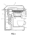
- a beverage maker 1 comprises a housing 2 with a lid 3 and a removable beverage preparation assembly 4.
- the housing 2 has a platform 5, on which a cup 6 can be placed, an upright body 7 and a beverage preparation assembly support 8 that accommodates the removable beverage preparation assembly 4 and supports it in a position over the cup 6 on the platform 5.
- the upright body 7 houses a hot water delivery system comprising a water reservoir 9, a water pump 10, a water heater 11 and a conduit 12.
- the water reservoir 9 extends over the full height of the upright body 7 and is open at its top so that it can easily be filled with water.
- the water pump 10 is connected to draw water from the bottom of the water reservoir 9 and push it through the water heater 11 and, from there, along the conduit 12.
- the lid 3 is hinged at the top of the upright body 7 by a hinge 13 and, when it is closed, a bottom surface 14 of the lid 3 closes the opening in the reservoir 9 to prevent water in the reservoir 9 spilling out.
- the conduit 12 extends into the lid 3 and opens into a recess 15 on the bottom surface of the lid 3. Again when the lid 3 is closed, the recess 15 is positioned above the beverage preparation assembly support 8 and consequently the removable beverage preparation assembly 4 when positioned in the support 8. As described in more detail below, together with the beverage preparation assembly 4, the recess 15 forms a beverage preparation chamber 16.
- the beverage preparation assembly 4 comprises a cup shaped body 17.
- a rim 18 running around the outside of an open end of the cup shaped body 17 is arranged to rest on tabs 19 of the support 8.
- the assembly 4 is positioned on and removed from the support 8 by the rim 18 of the cup shaped body 17 sliding along the tabs 19 of the support 8.
- a bayonet fitting or such like is provided.
- a handle extends from the cup shaped body 17 to allow the assembly 4 to be manipulated.
- the diameter of the cup shaped body 17 is largest at the open end, which is uppermost in use. Inward of open end is a filter ledge 20.
- the filter ledge 20 is a lip extending around the inside surface of the cup shaped body 17 for supporting the perimeter of a filter pad 21.
- the filter pad 21 is a disc of filter paper holding a wad of coffee grounds. More specifically, two circular pieces of filter paper sandwich the coffee grounds and are glued, or otherwise joined, together at their perimeter.
- the filter pad 21 could equally hold granules for making other beverages, such as mocha coffee, hot chocolate and so on.
- the filter ledge 20 of the cup shaped body 17 has a slightly smaller diameter than the perimeter of the filter pad 21 so that, when the filter pad is placed inside the cup shaped body 17, its perimeter rests on the filter ledge 20.
- a support ledge 22 Inward of the filter ledge 20 is a support ledge 22. Similar to the filter ledge 20, the support ledge 22 is a lip extending around the inside surface of the cup shaped body 17. However the support ledge 22 is arranged to support a filter support 23.
- the filter support 23 is a disc that, in this embodiment, has a slightly smaller diameter than the filter pad 21. Again similar to the filter ledge 20, the support ledge 22 has a slightly smaller diameter than the perimeter of filter support 23 so that, when the filter support 23 is placed inside the cup shaped body 17, its perimeter rests on the support ledge 22. When in position in the cup shaped body 17, the filter support 23 is below the filter pad 21 and supports the underside of the pad 21. It also forms the base of the beverage preparation chamber 16.
- the beverage preparation chamber 16 is bounded by the recess 15 of the lid 3, the filter support 23 and a side wall of the cup shaped body 17.
- An o-ring seal 26 is provided around the recess 15 of the lid 3 for engagement with the assembly 4 to seal the chamber 16.
- the filter support 23 has a plurality of projections 24 on its upper surface and a nozzle 25.
- the projections 24 support the underside of the filter pad 21.
- the nozzle 25 extends though the filter support 23, i.e. from the beverage preparation chamber 16 to the underside of the filter support 23 in use and allows prepared beverage to exit the beverage preparation chamber 16.
- the nozzle is an aperture having a diameter substantially between 0.75mm and 0.9mm (e.g. 0.83mm). This means that, with a pressure of around 1 bar over atmospheric pressure in the beverage preparation chamber, prepared beverage leaves the nozzle 25 as a jet of liquid. This jet aids foam creation, as described below.
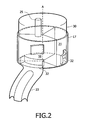
- the cup shaped body 17 Inward of the support ledge 22, the cup shaped body 17 is closed to form a housing for a foam unit 30.
- the cup shaped body 17 houses the foam unit 30 under the nozzle 25 of the filter support 23 so that prepared beverage can pass through the nozzle 25 to the foam unit 30.
- the foam unit 30 comprises a receptacle divided into several foam compartments 31.
- the foam compartments 31 are open at one end. This end forms the top of the unit 30 in use.
- the foam unit 30 has three foam compartments 31, each of which comprises a segment of the receptacle.
- the receptacle is cylindrical. Looking at the circular cross-section of the cylinder, the compartments are sectors of the circle. In other words, the compartments might be referred to as cylindrical sectors. This can be seen more clearly in figure 2 . Of course, different numbers of compartments 31 and different shapes are used in other embodiments.
- Each compartment 31 of the foam unit 30 has an outlet opening 32.
- the outlet openings 32 each comprise a recess in the side wall of the receptacle with apertures (not shown) arranged to allow prepared beverage to pass out of respective compartments 31.
- the outlets 32 can engage with a spout 33 that extends from the cup shaped body 17 and from which beverage can be dispensed into the cup 6.
- the foam unit 30 is mounted to the cup shaped body 17 of the removable beverage preparation assembly 4 about an axis A.
- the axis A is substantially upright in use so that the foam compartments 31 can rotate around it in a plane that is horizontal in use.
- the axis A is the major axis running along the centre of the cylindrical receptacle that forms the foam unit 30.
- the nozzle 25 is offset from the central axis A of the unit 30 and, as the foam unit 30 is rotated, the compartments 31 pass one by one under the nozzle 25.
- An indexing mechanism (not shown) is provided to resiliently hold each of the compartments 31 in a position directly under the nozzle 25.
- an indexing member is provided on the unit 30 comprising a domed element biased away from the outer surface of the unit 30. As the unit 30 is rotated, the element cooperates with appropriately positioned recesses on the inner surface of the cup shaped body 17 to resiliently hold the unit 30 in an indexing position.
- the unit 30 can be indexed by other means in other embodiments.
- a rotation mechanism (not shown) is also provided. More specifically, a lever cooperates with a ratchet mechanism disposed around the axis A so that moving the lever to and fro causes the unit 30 to rotate in a clockwise direction.
- the unit 30 can be rotated by other means in other embodiments.
- a user To make a beverage, a user first fills the water reservoir 9 with water. This is done by opening the lid 3 and pouring water into the top of the reservoir 9. With the lid 3 open, the user also inserts a filter pad 21 into the removable beverage preparation assembly 4. More specifically, a filter pad 21 is placed on the filter support 23. The lid 3 is then shut.
- the water pump 10 pumps water through the water heater 11, where it is heated to a desired temperature, e.g. slightly below boiling point, and through the conduit 12 to the beverage preparation chamber 16. Water passes into the beverage preparation chamber 16 at a pressure of around 1 bar (e.g. 0.8 bar to 1.6 bar) over atmospheric pressure. The water arrives at the top of the filter pad 21 and is pressed through the filter pad 21, where it mixes with the coffee grounds or beverage granules in the filter pad 21 to form a beverage. The prepared beverage passes out of the bottom of the filter pad 21 to the filter support 22. The filter support 22 directs the prepared beverage though the nozzle 25 to the foam unit 30.
- a desired temperature e.g. slightly below boiling point
- the prepared beverage enters the foam compartment 31 of the unit 30 that is below the nozzle 25.
- foam is created.
- the outlet 32 from the compartment 31 is small enough that beverage exits the compartment 31 more slowly than it enters the compartment 31 through the nozzle 25.
- the compartment 31 therefore acts as a buffer temporarily storing some of the prepared beverage.
- the jet of liquid can interact with the stored beverage and this improves foam creation.
- the used filter pad 21 is replaced with a new filter pad 21.
- a user manipulates the rotation mechanism to rotate another of the foam compartments 31 into position under the nozzle 25.
- the beverage is therefore prepared using a different foam compartment 31, which is clean and free from residue from the previously prepared beverage. Only when all (three) of the foam compartments have been used, need the foam compartments 31 be cleaned by a user.
- one of the foam compartments 31 is replaced by a bypass chamber.
- the bypass chamber has a surface for slowing prepared beverage exiting the nozzle without creating foam.
- the surface may slope from in-line with the jet to one side.
- the outlet opening 32 of the compartment is retained to allow the beverage to be dispenses from the bypass chamber.
Landscapes
- Engineering & Computer Science (AREA)
- Food Science & Technology (AREA)
- Apparatus For Making Beverages (AREA)
- Tea And Coffee (AREA)
Abstract
Description
- This invention relates to a beverage maker incorporating multiple beverage collection chambers and to beverage preparation assembly that can be removably mounted on a beverage maker and that incorporates multiple beverage collection chambers.
- Many people prefer to consume beverages such as coffee with a layer of foam, or a so-called "crema layer" on top. Much effort has therefore been made to design both domestic and commercial beverage makers that reliably produce a layer of foam on such beverages. One such beverage maker is the applicants' Senseo® coffee maker. Coffee makers similar to this are described in patent publications
EP 0904717 andWO 03/055366 DE 3 346 280 A . - These coffee makers use coffee pads which each comprise a disc shape wad of coffee grounds enclosed in filter paper. To make coffee, a coffee pad is inserted in a coffee preparation chamber of the coffee maker. Hot water is supplied to the chamber at pressure (typically around 1 bar). As the hot water passes through the pad in the chamber, coffee extract mixes with the hot water to produce coffee. Prepared coffee is discharged from the coffee preparation chamber through a nozzle to a foam chamber. The nozzle is sufficiently small that the prepared coffee exits the nozzle as jet of liquid due to pressure in the coffee preparation chamber. This jet enters the foam chamber and, as the jet impacts a side of the foam chamber, or the surface of coffee already in the foam chamber, small bubbles are created in the coffee. These bubbles create a layer of foam on the surface of the coffee, i.e. the desired "crema layer". The prepared coffee, with its crema layer, is dispensed from the foam chamber through spout into a cup for drinking.
- It is common for beverage makers to make several different flavour drinks. For example, the Senseo® coffee maker can be used to make coffee of different strengths or even mocha coffee (chocolate flavoured coffee) and such like by using different coffee pads. In other beverage makers, it may be possible to make hot chocolate, tea or other beverages. However, where a beverage maker has only one liquid path (e.g. foam chamber, spout etc.) for dispensing beverages, either the liquid path must be cleaned between making different flavour beverages or some contamination of a beverage occurs from the residue of previously prepared beverages left in the liquid path. The present invention seeks to overcome this problem.
- The applicants' have recognised that the problem is particularly acute where a foam chamber is included in the liquid path, such as in the coffee maker described above. The foam produced in the foam chamber tends to be stickier than the beverage itself. Furthermore, foam chambers are usually designed to slow down the flow of beverage to allow foam to be created and slow moving liquids tend to leave greater residue. This results in significant beverage residue being left in the foam chamber to contaminate any beverages that are made subsequently.
- According to one aspect of the present invention; there is provided a beverage maker comprising:
- a beverage preparation chamber in which beverage can be prepared;
- a hot water delivery system for delivering hot water to the beverage preparation chamber;
- a discharge opening for discharging prepared beverage from the beverage preparation chamber;
- multiple beverage collection chambers for receiving prepared beverage discharged though the discharge opening; and
- one or more outlets for dispensing beverage from the beverage collection chambers into a cup for drinking,
- According to another aspect of the present invention, there is provided a method of making a beverage, the method comprising:
- providing hot water to a beverage making chamber in which the beverage is prepared;
- discharging prepared beverage from the beverage making chamber through a discharge opening;
- receiving prepared beverage discharged through the discharge opening in one of multiple beverage collection chambers; and
- dispensing beverage from the beverage collection chamber through an outlet into a cup for drinking,
- This allows different beverage collection chambers to be selected from time to time. For example, one beverage collection chamber can be used during the preparation of one beverage and another beverage collection chamber can be used during preparation of another beverage. Contamination of a beverage by residue of a previously prepared beverage is avoided by using different beverage collection chambers to collect and dispense each beverage. Beverages of different flavours can therefore be prepared without cross-contamination. Furthermore, the coffee maker can be used to prepare several beverages, either of the same or different flavours, before it needs to be cleaned. The frequency with which the beverage maker needs to be cleaned is therefore reduced.
- The beverage maker may be any sort of beverage maker that includes a beverage collection chamber. For example, the beverage maker might be a vending machine. However, the beverage maker is typically a commercial or domestic beverage maker. In particular, it may be a filter or filter pad type beverage maker. The beverage preparation chamber may therefore include a filter support for supporting a filter. In particular, the filter support may comprise a surface and have projections for supporting the filter away from the surface.
- The invention finds particular utility in beverage makers that incorporate foam creation. The pad-type beverage maker described above is one such coffee maker. The beverage collection chambers may therefore be foam chambers. In other words, the beverage collection chambers may comprise foam chambers in which foam can be created in the prepared beverage.
- Similarly, the discharge opening may be adapted to aid foam creation. It may therefore comprise a nozzle. The nozzle might comprise an aperture having a diameter sufficiently small to discharge the beverage as a jet to create foam in the beverage in the foam chamber. To achieve this, the aperture may have a width or diameter substantially between 0.75 mm to 0.9 mm (e.g. 0.83mm). As described above, when the jet of beverage impacts a surface in the foam chamber, foam is created. Of course, in other examples, a foam creation device, such as a mixer, stirrer or compressed air supply may be provided to create foam.
- Whilst the beverage maker described above is effective in producing foam in beverages, the applicants recognise that foam creation is not always desirable. Some users may prefer beverages without foam and certain beverages, such as tea, are not usually consumed with a "crema layer". In one example, the beverage maker may therefore usefully further comprise a bypass chamber that can be aligned with the discharge opening to receive prepared beverage discharged from the discharge opening so that it bypasses the foam chambers and foam creation is avoided.
- Typically, the beverage maker has only one discharge opening or nozzle. This might be provided in the filter support for example. The discharge opening might be moveable in the beverage maker to adjust its alignment with the beverage collection chambers. However, it is preferred that beverage collection chambers are moveable in the beverage maker to adjust their alignment relative to the discharge opening. For example, the beverage maker may further comprise a beverage collection unit for housing the beverage collection chambers. This beverage collection unit may be moveable to adjust the alignment of the beverage collection chambers. It is particularly preferred that the beverage collection chambers each comprise a segment of the beverage collection unit (e.g. a cylindrical sector). The beverage collection unit might be rotatable in the beverage maker to adjust the alignment of the beverage collection chambers relative to the nozzle.
- Usually, the beverage maker has only one outlet. This outlet cooperates with the beverage collection chamber aligned with the discharge opening to allow beverage to be dispensed from the beverage collection chamber. For example, each of the beverage collection chambers may have an opening that aligns with the outlet when that beverage collection chamber is aligned with the discharge opening. To improve alignment, the beverage collection chambers typically incorporate an indexing mechanism.
- In other examples, the beverage maker may have a separate outlet for each beverage collection chamber. Whilst this might result in the beverage maker being bulkier, it is simpler, as the beverage collection chambers do not need to be selectively aligned to a shared outlet.
- The applicants have recognised that a beverage preparation assembly incorporating the multiple foam chambers described above could be removably fitted to a conventional beverage maker.
- According to another aspect of the present invention, there is therefore provided a beverage preparation assembly that can be removably mounted on a beverage maker, the assembly comprising:
- a beverage preparation chamber in which beverage can be prepared;
- a discharge opening for discharging prepared beverage from the beverage preparation chamber;
- multiple beverage collection chambers for receiving prepared beverage discharged though the discharge opening; and
- one or more outlets for dispensing beverage from the beverage collection chambers into a cup for drinking,
- This beverage preparation assembly may include any of the preferred features on the invention described above.
- Preferred embodiments of the invention will now be described, by way of example only, with reference to the accompanying drawings, in which:
-
Figure 1 is a schematic illustration showing sectional side view of a beverage maker according to the invention; and -
Figure 2 is a schematic illustration of a beverage preparation assembly of the beverage maker offigure 1 . - Referring to
figure 1 , abeverage maker 1 comprises ahousing 2 with alid 3 and a removablebeverage preparation assembly 4. Thehousing 2 has aplatform 5, on which acup 6 can be placed, anupright body 7 and a beveragepreparation assembly support 8 that accommodates the removablebeverage preparation assembly 4 and supports it in a position over thecup 6 on theplatform 5. - The
upright body 7 houses a hot water delivery system comprising awater reservoir 9, awater pump 10, awater heater 11 and aconduit 12. In this embodiment, thewater reservoir 9 extends over the full height of theupright body 7 and is open at its top so that it can easily be filled with water. Thewater pump 10 is connected to draw water from the bottom of thewater reservoir 9 and push it through thewater heater 11 and, from there, along theconduit 12. - The
lid 3 is hinged at the top of theupright body 7 by ahinge 13 and, when it is closed, abottom surface 14 of thelid 3 closes the opening in thereservoir 9 to prevent water in thereservoir 9 spilling out. Theconduit 12 extends into thelid 3 and opens into arecess 15 on the bottom surface of thelid 3. Again when thelid 3 is closed, therecess 15 is positioned above the beveragepreparation assembly support 8 and consequently the removablebeverage preparation assembly 4 when positioned in thesupport 8. As described in more detail below, together with thebeverage preparation assembly 4, therecess 15 forms abeverage preparation chamber 16. - The
beverage preparation assembly 4 comprises a cup shapedbody 17. Arim 18 running around the outside of an open end of the cup shapedbody 17 is arranged to rest ontabs 19 of thesupport 8. In this embodiment, theassembly 4 is positioned on and removed from thesupport 8 by therim 18 of the cup shapedbody 17 sliding along thetabs 19 of thesupport 8. In other embodiments, a bayonet fitting or such like is provided. A handle (not shown) extends from the cup shapedbody 17 to allow theassembly 4 to be manipulated. - The diameter of the cup shaped
body 17 is largest at the open end, which is uppermost in use. Inward of open end is afilter ledge 20. Thefilter ledge 20 is a lip extending around the inside surface of the cup shapedbody 17 for supporting the perimeter of afilter pad 21. In this embodiment, thefilter pad 21 is a disc of filter paper holding a wad of coffee grounds. More specifically, two circular pieces of filter paper sandwich the coffee grounds and are glued, or otherwise joined, together at their perimeter. Thefilter pad 21 could equally hold granules for making other beverages, such as mocha coffee, hot chocolate and so on. Thefilter ledge 20 of the cup shapedbody 17 has a slightly smaller diameter than the perimeter of thefilter pad 21 so that, when the filter pad is placed inside the cup shapedbody 17, its perimeter rests on thefilter ledge 20. - Inward of the
filter ledge 20 is asupport ledge 22. Similar to thefilter ledge 20, thesupport ledge 22 is a lip extending around the inside surface of the cup shapedbody 17. However thesupport ledge 22 is arranged to support afilter support 23. Thefilter support 23 is a disc that, in this embodiment, has a slightly smaller diameter than thefilter pad 21. Again similar to thefilter ledge 20, thesupport ledge 22 has a slightly smaller diameter than the perimeter offilter support 23 so that, when thefilter support 23 is placed inside the cup shapedbody 17, its perimeter rests on thesupport ledge 22. When in position in the cup shapedbody 17, thefilter support 23 is below thefilter pad 21 and supports the underside of thepad 21. It also forms the base of thebeverage preparation chamber 16. More specifically, thebeverage preparation chamber 16 is bounded by therecess 15 of thelid 3, thefilter support 23 and a side wall of the cup shapedbody 17. An o-ring seal 26 is provided around therecess 15 of thelid 3 for engagement with theassembly 4 to seal thechamber 16. - The
filter support 23 has a plurality ofprojections 24 on its upper surface and anozzle 25. Theprojections 24 support the underside of thefilter pad 21. Thenozzle 25 extends though thefilter support 23, i.e. from thebeverage preparation chamber 16 to the underside of thefilter support 23 in use and allows prepared beverage to exit thebeverage preparation chamber 16. In this example, the nozzle is an aperture having a diameter substantially between 0.75mm and 0.9mm (e.g. 0.83mm). This means that, with a pressure of around 1 bar over atmospheric pressure in the beverage preparation chamber, prepared beverage leaves thenozzle 25 as a jet of liquid. This jet aids foam creation, as described below. - Inward of the
support ledge 22, the cup shapedbody 17 is closed to form a housing for afoam unit 30. In other words, the cup shapedbody 17 houses thefoam unit 30 under thenozzle 25 of thefilter support 23 so that prepared beverage can pass through thenozzle 25 to thefoam unit 30. - The
foam unit 30 comprises a receptacle divided into several foam compartments 31. The foam compartments 31 are open at one end. This end forms the top of theunit 30 in use. In this embodiment, thefoam unit 30 has threefoam compartments 31, each of which comprises a segment of the receptacle. The receptacle is cylindrical. Looking at the circular cross-section of the cylinder, the compartments are sectors of the circle. In other words, the compartments might be referred to as cylindrical sectors. This can be seen more clearly infigure 2 . Of course, different numbers ofcompartments 31 and different shapes are used in other embodiments. - Each
compartment 31 of thefoam unit 30 has anoutlet opening 32. Theoutlet openings 32 each comprise a recess in the side wall of the receptacle with apertures (not shown) arranged to allow prepared beverage to pass out ofrespective compartments 31. Theoutlets 32 can engage with aspout 33 that extends from the cup shapedbody 17 and from which beverage can be dispensed into thecup 6. - The
foam unit 30 is mounted to the cup shapedbody 17 of the removablebeverage preparation assembly 4 about an axis A. The axis A is substantially upright in use so that the foam compartments 31 can rotate around it in a plane that is horizontal in use. In this embodiment, the axis A is the major axis running along the centre of the cylindrical receptacle that forms thefoam unit 30. Thenozzle 25 is offset from the central axis A of theunit 30 and, as thefoam unit 30 is rotated, thecompartments 31 pass one by one under thenozzle 25. - An indexing mechanism (not shown) is provided to resiliently hold each of the
compartments 31 in a position directly under thenozzle 25. For example, an indexing member is provided on theunit 30 comprising a domed element biased away from the outer surface of theunit 30. As theunit 30 is rotated, the element cooperates with appropriately positioned recesses on the inner surface of the cup shapedbody 17 to resiliently hold theunit 30 in an indexing position. Of course, theunit 30 can be indexed by other means in other embodiments. - In this embodiment, a rotation mechanism (not shown) is also provided. More specifically, a lever cooperates with a ratchet mechanism disposed around the axis A so that moving the lever to and fro causes the
unit 30 to rotate in a clockwise direction. Of course, theunit 30 can be rotated by other means in other embodiments. - To make a beverage, a user first fills the
water reservoir 9 with water. This is done by opening thelid 3 and pouring water into the top of thereservoir 9. With thelid 3 open, the user also inserts afilter pad 21 into the removablebeverage preparation assembly 4. More specifically, afilter pad 21 is placed on thefilter support 23. Thelid 3 is then shut. - The
water pump 10 pumps water through thewater heater 11, where it is heated to a desired temperature, e.g. slightly below boiling point, and through theconduit 12 to thebeverage preparation chamber 16. Water passes into thebeverage preparation chamber 16 at a pressure of around 1 bar (e.g. 0.8 bar to 1.6 bar) over atmospheric pressure. The water arrives at the top of thefilter pad 21 and is pressed through thefilter pad 21, where it mixes with the coffee grounds or beverage granules in thefilter pad 21 to form a beverage. The prepared beverage passes out of the bottom of thefilter pad 21 to thefilter support 22. Thefilter support 22 directs the prepared beverage though thenozzle 25 to thefoam unit 30. - The prepared beverage enters the
foam compartment 31 of theunit 30 that is below thenozzle 25. As the jet of liquid formed by thenozzle 25 impacts the bottom of thefoam compartment 31, foam is created. Furthermore, theoutlet 32 from thecompartment 31 is small enough that beverage exits thecompartment 31 more slowly than it enters thecompartment 31 through thenozzle 25. Thecompartment 31 therefore acts as a buffer temporarily storing some of the prepared beverage. The jet of liquid can interact with the stored beverage and this improves foam creation. As the beverage leaves thecompartment 31 through theoutlet 32, it passes along thespout 33 and is dispensed into thecup 6 for drinking. - When it is desired to make another beverage, the used
filter pad 21 is replaced with anew filter pad 21. Also, a user manipulates the rotation mechanism to rotate another of the foam compartments 31 into position under thenozzle 25. The beverage is therefore prepared using adifferent foam compartment 31, which is clean and free from residue from the previously prepared beverage. Only when all (three) of the foam compartments have been used, need the foam compartments 31 be cleaned by a user. - In another embodiment, one of the foam compartments 31 is replaced by a bypass chamber. The bypass chamber has a surface for slowing prepared beverage exiting the nozzle without creating foam. For example, the surface may slope from in-line with the jet to one side. The
outlet opening 32 of the compartment is retained to allow the beverage to be dispenses from the bypass chamber. - The described embodiments of the invention are only embodiments of how the invention may be implemented. Modifications, variations and changes to the described embodiments will occur to those having appropriate skills and knowledge. These modifications, variations and changes may be made without departure from the scope of the invention as defined in the claims.
Claims (17)
- A beverage maker (1) comprising:a beverage preparation chamber (16) in which beverage can be prepared;a hot water delivery system (9,10,11,12) for delivering hot water to the beverage preparation chamber (16);a discharge opening (25) for discharging prepared beverage from the beverage preparation chamber (16);multiple beverage collection chambers (31) for receiving prepared beverage discharged though the discharge opening (25); andone or more outlets (33) for dispensing beverage from the beverage collection chambers (31) into a cup (6) for drinking,wherein the alignment of the beverage collection chambers (31) relative to the discharge opening (25) is adjustable to position any one of the beverage collection chambers (31) to receive beverage from the discharge opening (25) instead of the other beverage collection chamber(s) (31).
- The beverage maker (1) of claim 1, wherein the beverage preparation chamber (16) houses a filter support (23) for supporting a filter (21).
- The beverage maker (1) of claim 2, wherein the filter support (23) comprises a surface and projections (24) for supporting the filter (21) away from the surface.
- The beverage maker (1) of any one of the preceding claims, having only one discharge opening (25) for discharging prepared beverage from the beverage preparation chamber (16).
- The beverage maker (1) of any one of the preceding claims, wherein the beverage collection chambers (31) are moveable in the beverage maker (1) to adjust their alignment relative to the discharge opening (25).
- The beverage maker (1) of any one of the preceding claims, further comprising a beverage collection unit (30) for housing the beverage collection chambers (31).
- The beverage maker (1) of claim 6, wherein the beverage collection chambers (31) each comprise a segment of the beverage collection unit (30).
- The beverage maker (1) of claim 6 or claim 7, wherein the beverage collection unit (30) is rotatable in the beverage maker (1) to adjust the alignment of the beverage collection chambers (31) relative to the discharge opening (25).
- The beverage maker (1) of any one of the preceding claims, comprising only one outlet (33) that cooperates with the beverage collection chamber (31) aligned with the discharge opening (25) to allow beverage to be dispensed from the beverage collection chamber (31).
- The beverage maker (1) of any one of claims 1 to 8, comprising a separate outlet (33) for each beverage collection chamber (31).
- The beverage maker (1) of any one of the preceding claims, wherein the discharge opening (25) comprises a nozzle.
- The beverage maker (1) of claim 11, wherein the nozzle comprises an aperture having a diameter sufficiently small to discharge the beverage as a jet to create foam in the beverage in the beverage collection chamber (31).
- The beverage maker (1) of claim 12, wherein the aperture has a width substantially between 0.75 mm and 0.9 mm.
- The beverage maker (1) of any one of the preceding claims, wherein the beverage collection chambers (31) comprise foam chambers in which foam can be created in the prepared beverage.
- The beverage maker (1) of claim 14, further comprising a bypass chamber that can be aligned with the discharge opening (25) to receive prepared beverage discharged from the discharge opening (25) so that it bypasses the foam chambers (31) and foam creation is avoided
- A beverage preparation assembly (4) that can be removably mounted on a beverage maker (1), the assembly (4) comprising:a beverage preparation chamber (16) in which beverage can be prepared;a discharge opening (25) for discharging prepared beverage from the beverage preparation chamber (16);multiple beverage collection chambers (31) for receiving prepared beverage discharged though the discharge opening (25); andone or more outlets (33) for dispensing beverage from the beverage collection chambers (31) into a cup (6) for drinking,wherein the alignment of the beverage collection chambers (31) relative to the discharge opening (25) is adjustable to position any one of the beverage collection chambers (31) to receive beverage from the discharge opening (25) instead of the other beverage collection chamber(s) (31).
- A method of making a beverage, the method comprising:providing hot water to a beverage making chamber (16) in which the beverage is prepared;discharging prepared beverage from the beverage making chamber (16) through a discharge opening (25);receiving prepared beverage discharged through the discharge opening (25) in one of multiple beverage collection chambers (31); anddispensing beverage from the beverage collection chamber (31) through an outlet into a cup (6) for drinking,wherein the method includes adjusting the alignment of the beverage collection chambers (31) relative to the discharge opening (25) to position any one of the beverage collection chambers (31) to receive beverage from the discharge opening (25) instead of the other beverage collection chamber(s) (31).
Applications Claiming Priority (2)
| Application Number | Priority Date | Filing Date | Title |
|---|---|---|---|
| GBGB0329744.7A GB0329744D0 (en) | 2003-12-23 | 2003-12-23 | A beverage maker incorporating multiple beverage collection chambers |
| PCT/IB2004/052814 WO2005063094A1 (en) | 2003-12-23 | 2004-12-15 | A beverage maker incorporating multiple beverage collection chambers |
Publications (2)
| Publication Number | Publication Date |
|---|---|
| EP1699329A1 EP1699329A1 (en) | 2006-09-13 |
| EP1699329B1 true EP1699329B1 (en) | 2009-03-18 |
Family
ID=30776309
Family Applications (1)
| Application Number | Title | Priority Date | Filing Date |
|---|---|---|---|
| EP04806575A Not-in-force EP1699329B1 (en) | 2003-12-23 | 2004-12-15 | A beverage maker incorporating multiple beverage collection chambers |
Country Status (8)
| Country | Link |
|---|---|
| US (1) | US20080069930A1 (en) |
| EP (1) | EP1699329B1 (en) |
| JP (1) | JP2007516033A (en) |
| CN (1) | CN100475110C (en) |
| AT (1) | ATE425689T1 (en) |
| DE (1) | DE602004020107D1 (en) |
| GB (1) | GB0329744D0 (en) |
| WO (1) | WO2005063094A1 (en) |
Families Citing this family (102)
| Publication number | Priority date | Publication date | Assignee | Title |
|---|---|---|---|---|
| NL1020833C2 (en) | 2002-06-12 | 2003-12-15 | Sara Lee De Nv | Device for preparing a beverage suitable for consumption with a fine-bubble froth layer. |
| NL1020836C2 (en) | 2002-06-12 | 2003-12-15 | Sara Lee De Nv | Device and method for preparing coffee with a fine-bubble froth layer, in particular cappuccino. |
| NL1032292C2 (en) * | 2004-08-12 | 2007-05-30 | Sara Lee De Nv | Beverage preparing system is designed for producing beverage with froth layer and beverage without froth layer in two different conditions |
| NL1026834C2 (en) | 2004-08-12 | 2006-02-14 | Sara Lee De Nv | Prepare tea using a tea pad and coffee maker. |
| NL1029503C2 (en) * | 2005-07-12 | 2007-01-15 | Sara Lee De Nv | System and method for preparing a beverage suitable for consumption, as well as a use of such a system, a receiving chamber and a container. |
| CN101321484B (en) * | 2005-12-01 | 2011-03-16 | 皇家飞利浦电子股份有限公司 | A tea making device having an improved liquid collection chamber |
| DE202006008409U1 (en) * | 2006-05-27 | 2006-08-10 | Eugster/Frismag Ag | Dissolving unit for instant powder, especially powdered milk, comprises a flow inducing member, a foam chamber and a nozzle |
| GB2452981B (en) * | 2007-09-21 | 2012-10-17 | Otter Controls Ltd | Electrical appliances |
| ES2347305T5 (en) | 2008-01-29 | 2019-04-25 | Douwe Egberts Bv | System and method to prepare a drink |
| JP2013521255A (en) | 2010-03-04 | 2013-06-10 | バイエル・インテレクチュアル・プロパティ・ゲゼルシャフト・ミット・ベシュレンクテル・ハフツング | Fluoroalkyl-substituted 2-amidobenzimidazoles and their use to enhance stress tolerance in plants |
| CN102971315B (en) | 2010-05-05 | 2015-07-22 | 拜耳知识产权有限责任公司 | Thiazol derivatives as pest control agents |
| RU2596929C2 (en) | 2010-06-18 | 2016-09-10 | Байер Интеллектчуал Проперти Гмбх | Combination of active substance with insecticidal and acaricidal properties, use of such combinations, agrochemical composition and preparation method thereof and method of controlling animal pests |
| WO2012000896A2 (en) | 2010-06-28 | 2012-01-05 | Bayer Cropscience Ag | Heterocyclic compounds as agents for pest control |
| WO2012004293A2 (en) | 2010-07-08 | 2012-01-12 | Bayer Cropscience Ag | Insecticide and fungicide active ingredient combinations |
| JP2012017289A (en) | 2010-07-08 | 2012-01-26 | Bayer Cropscience Ag | Pesticidal pyrroline derivative |
| JP2012062267A (en) | 2010-09-15 | 2012-03-29 | Bayer Cropscience Ag | Pesticidal pyrroline n-oxide derivative |
| JP2012082186A (en) | 2010-09-15 | 2012-04-26 | Bayer Cropscience Ag | Insecticidal arylpyrrolidines |
| WO2012045680A2 (en) | 2010-10-04 | 2012-04-12 | Bayer Cropscience Ag | Insecticidal and fungicidal active substance combinations |
| EP2630125B1 (en) | 2010-10-21 | 2016-08-24 | Bayer Intellectual Property GmbH | N-benzyl heterocyclic carboxamides |
| JP2013542215A (en) | 2010-11-02 | 2013-11-21 | バイエル・インテレクチユアル・プロパテイー・ゲー・エム・ベー・ハー | N-hetarylmethylpyrazolyl carboxamides |
| EP2640706B1 (en) | 2010-11-15 | 2017-03-01 | Bayer Intellectual Property GmbH | N-aryl pyrazole(thio)carboxamides |
| JP2014503503A (en) | 2010-11-29 | 2014-02-13 | バイエル・インテレクチユアル・プロパテイー・ゲー・エム・ベー・ハー | α, β-unsaturated imines |
| EP2645856A1 (en) | 2010-12-01 | 2013-10-09 | Bayer Intellectual Property GmbH | Use of fluopyram for controlling nematodes in crops and for increasing yield |
| TWI667347B (en) | 2010-12-15 | 2019-08-01 | 瑞士商先正達合夥公司 | Soybean event syht0h2 and compositions and methods for detection thereof |
| EP2471363A1 (en) | 2010-12-30 | 2012-07-04 | Bayer CropScience AG | Use of aryl-, heteroaryl- and benzylsulfonamide carboxylic acids, -carboxylic acid esters, -carboxylic acid amides and -carbonitriles and/or its salts for increasing stress tolerance in plants |
| CA2827398A1 (en) | 2011-02-17 | 2012-08-23 | Bayer Intellectual Property Gmbh | Substituted 3-(biphenyl-3-yl)-8,8-difluoro-4-hydroxy-1-azaspiro[4.5]dec-3-en-2-ones for therapy |
| CA2827304C (en) | 2011-02-17 | 2018-11-13 | Bayer Intellectual Property Gmbh | Use of sdhi fungicides on conventionally bred asr-tolerant, stem canker resistant and/or frog-eye leaf spot resistant soybean varieties |
| BR112013021019A2 (en) | 2011-02-17 | 2019-02-26 | Bayer Ip Gmbh | use of sdhi fungicides in conventionally cultivated soybean varieties with Asian soybean rust (asr) tolerance, stem cancer resistance and / or frog eye leaf spot |
| JP5987007B2 (en) | 2011-03-01 | 2016-09-06 | バイエル・インテレクチュアル・プロパティ・ゲゼルシャフト・ミット・ベシュレンクテル・ハフツングBayer Intellectual Property GmbH | 2-Acyloxypyrrolin-4-ones |
| AR085509A1 (en) | 2011-03-09 | 2013-10-09 | Bayer Cropscience Ag | INDOL- AND BENCIMIDAZOLCARBOXAMIDS AS INSECTICIDES AND ACARICIDES |
| EP2683239A1 (en) | 2011-03-10 | 2014-01-15 | Bayer Intellectual Property GmbH | Use of lipochito-oligosaccharide compounds for safeguarding seed safety of treated seeds |
| EP2686303B1 (en) | 2011-03-18 | 2016-01-20 | Bayer Intellectual Property GmbH | N-(3-carbamoylphenyl)-1h-pyrazole-5-carboxamide derivatives and their use for combating animal pests |
| AR090010A1 (en) | 2011-04-15 | 2014-10-15 | Bayer Cropscience Ag | 5- (CICLOHEX-2-EN-1-IL) -PENTA-2,4-DIENOS AND 5- (CICLOHEX-2-EN-1-IL) -PENT-2-EN-4-INOS REPLACED AS ACTIVE PRINCIPLES AGAINST THE ABIOTIC STRESS OF PLANTS, USES AND TREATMENT METHODS |
| AR085585A1 (en) | 2011-04-15 | 2013-10-09 | Bayer Cropscience Ag | VINIL- AND ALQUINILCICLOHEXANOLES SUBSTITUTED AS ACTIVE PRINCIPLES AGAINST STRIPS ABIOTIQUE OF PLANTS |
| AR085568A1 (en) | 2011-04-15 | 2013-10-09 | Bayer Cropscience Ag | 5- (BICYCLE [4.1.0] HEPT-3-EN-2-IL) -PENTA-2,4-DIENOS AND 5- (BICYCLE [4.1.0] HEPT-3-EN-2-IL) -PENT- 2-IN-4-INOS REPLACED AS ACTIVE PRINCIPLES AGAINST ABIOTIC STRESS OF PLANTS |
| EP2535334A1 (en) | 2011-06-17 | 2012-12-19 | Bayer CropScience AG | Crystalline modifications of penflufen |
| EP2540163A1 (en) | 2011-06-30 | 2013-01-02 | Bayer CropScience AG | Nematocide N-cyclopropyl-sulfonylamide derivatives |
| WO2013004652A1 (en) | 2011-07-04 | 2013-01-10 | Bayer Intellectual Property Gmbh | Use of substituted isoquinolinones, isoquinolindiones, isoquinolintriones and dihydroisoquinolinones or in each case salts thereof as active agents against abiotic stress in plants |
| EP2736327B1 (en) | 2011-07-26 | 2018-02-21 | Clariant International Ltd | Etherified lactate esters, method for producing same and use of same to improve the effect of plant protecting agents |
| CA2843120A1 (en) | 2011-07-27 | 2013-01-31 | Bayer Intellectual Property Gmbh | Seed dressing for controlling phytopathogenic fungi |
| EP2561759A1 (en) | 2011-08-26 | 2013-02-27 | Bayer Cropscience AG | Fluoroalkyl-substituted 2-amidobenzimidazoles and their effect on plant growth |
| EA029850B9 (en) | 2011-09-16 | 2018-12-28 | Байер Интеллектуэль Проперти Гмбх | Use of isoxadifen-ethyl or isoxadifen for improving plant yield |
| UA115971C2 (en) | 2011-09-16 | 2018-01-25 | Байєр Інтеллектуал Проперті Гмбх | Use of acylsulfonamides for improving plant yield |
| MX362112B (en) | 2011-09-16 | 2019-01-07 | Bayer Ip Gmbh | Use of phenylpyrazolin-3-carboxylates for improving plant yield. |
| JP2013082632A (en) | 2011-10-05 | 2013-05-09 | Bayer Cropscience Ag | Agrochemical formulation and manufacturing method of the same |
| EP2604118A1 (en) | 2011-12-15 | 2013-06-19 | Bayer CropScience AG | Active ingredient combinations having insecticidal and acaricidal properties |
| CN104270946B (en) | 2011-12-19 | 2017-05-10 | 拜耳农作物科学股份公司 | Use of anthranilic acid diamide derivatives for pest control in transgenic crops |
| CN104011026B (en) | 2011-12-20 | 2016-07-20 | 拜耳知识产权股份有限公司 | Parasite killing virtue amide |
| EP2606726A1 (en) | 2011-12-21 | 2013-06-26 | Bayer CropScience AG | N-Arylamidine-substituted trifluoroethylsulfide derivatives as acaricides and insecticides |
| BR112014017552A8 (en) | 2012-01-21 | 2017-07-04 | Bayer Ip Gmbh | use of host defense inducers to control harmful basterian organisms in useful plants |
| WO2013135724A1 (en) | 2012-03-14 | 2013-09-19 | Bayer Intellectual Property Gmbh | Pesticidal arylpyrrolidines |
| JP6165847B2 (en) | 2012-05-16 | 2017-07-19 | バイエル・クロップサイエンス・アクチェンゲゼルシャフト | Insecticidal water-in-oil (W / O) formulation |
| IN2014DN08358A (en) | 2012-05-16 | 2015-05-08 | Bayer Cropscience Ag | |
| AR091104A1 (en) | 2012-05-22 | 2015-01-14 | Bayer Cropscience Ag | COMBINATIONS OF ACTIVE COMPOUNDS THAT INCLUDE A LIPO-CHYTOOLIGOSACARIDE DERIVATIVE AND A NEMATICIDE, INSECTICIDE OR FUNGICIDE COMPOUND |
| AR091202A1 (en) | 2012-05-30 | 2015-01-21 | Bayer Cropscience Ag | COMPOSITION THAT INCLUDES A BIOLOGICAL CONTROL AGENT AND AN INSECTICIDE |
| CN104640965A (en) | 2012-05-30 | 2015-05-20 | 科莱恩金融(Bvi)有限公司 | N-methyl-N-acylglucamine-containing composition |
| CN104540494B (en) | 2012-05-30 | 2017-10-24 | 科莱恩金融(Bvi)有限公司 | N methyl Ns acyl glucamides as solubilizer purposes |
| EP3243387A3 (en) | 2012-05-30 | 2017-12-13 | Bayer CropScience Aktiengesellschaft | Compositions comprising a biological control agent and an insecticide |
| MX2015001456A (en) | 2012-07-31 | 2015-05-08 | Bayer Cropscience Ag | Compositions comprising a pesticidal terpene mixture and an insecticide. |
| GB2504947B (en) | 2012-08-13 | 2015-01-14 | Kraft Foods R & D Inc | Beverage preparation machines |
| US20140057034A1 (en) * | 2012-08-22 | 2014-02-27 | Yung Hua Wang | Apparatus and method for making a beverage |
| US20150216168A1 (en) | 2012-09-05 | 2015-08-06 | Bayer Cropscience Ag | Use of substituted 2-amidobenzimidazoles, 2-amidobenzoxazoles and 2-amidobenzothiazoles or salts thereof as active substances against abiotic plant stress |
| CN105101800B (en) | 2012-10-02 | 2018-04-13 | 拜耳农作物科学股份公司 | Heterocyclic compound as insecticide |
| WO2014060381A1 (en) | 2012-10-18 | 2014-04-24 | Bayer Cropscience Ag | Heterocyclic compounds as pesticides |
| CN104884449A (en) | 2012-10-31 | 2015-09-02 | 拜尔农作物科学股份公司 | Novel heterocyclic compounds as pest control agents |
| DE102012021647A1 (en) | 2012-11-03 | 2014-05-08 | Clariant International Ltd. | Aqueous adjuvant compositions |
| UA117816C2 (en) | 2012-11-06 | 2018-10-10 | Байєр Кропсайєнс Акцієнгезелльшафт | Herbicidal combinations for tolerant soybean cultures |
| EA031510B1 (en) | 2012-11-30 | 2019-01-31 | Байер Кропсайенс Акциенгезельшафт | Binary fungicidal mixture |
| CA3082683A1 (en) | 2012-11-30 | 2014-06-05 | Bayer Cropscience Ag | Binary fungicidal mixtures |
| US20150289518A1 (en) | 2012-12-03 | 2015-10-15 | Bayer Cropscience Ag | Composition comprising a biological control agent and an insecticide |
| WO2014086753A2 (en) | 2012-12-03 | 2014-06-12 | Bayer Cropscience Ag | Composition comprising biological control agents |
| EP2925144A2 (en) | 2012-12-03 | 2015-10-07 | Bayer CropScience AG | Composition comprising a biological control agent and an insecticide |
| CN105451563A (en) | 2012-12-03 | 2016-03-30 | 拜耳作物科学股份公司 | Composition comprising biological control agents |
| ES2667555T3 (en) | 2012-12-03 | 2018-05-11 | Bayer Cropscience Ag | Composition comprising a biological control agent and an insecticide |
| US20150305334A1 (en) | 2012-12-05 | 2015-10-29 | Bayer Cropscience Ag | Use of substituted 1-(aryl ethynyl)-, 1-(heteroaryl ethynyl)-, 1-(heterocyclyl ethynyl)- and 1-(cycloalkenyl ethynyl)-cyclohexanols as active agents against abiotic plant stress |
| WO2014090765A1 (en) | 2012-12-12 | 2014-06-19 | Bayer Cropscience Ag | Use of 1-[2-fluoro-4-methyl-5-(2,2,2-trifluoroethylsulfinyl)phenyl]-5-amino-3-trifluoromethyl)-1 h-1,2,4 tfia zole for controlling nematodes in nematode-resistant crops |
| AR093996A1 (en) | 2012-12-18 | 2015-07-01 | Bayer Cropscience Ag | BACTERICIDAL COMBINATIONS AND BINARY FUNGICIDES |
| HUE036065T2 (en) | 2013-02-06 | 2018-06-28 | Bayer Cropscience Ag | Halogen-substituted pyrazole derivatives as pesticides |
| WO2014124379A1 (en) | 2013-02-11 | 2014-08-14 | Bayer Cropscience Lp | Compositions comprising a streptomyces-based biological control agent and an insecticide |
| WO2014124375A1 (en) | 2013-02-11 | 2014-08-14 | Bayer Cropscience Lp | Compositions comprising gougerotin and a biological control agent |
| CN105208865A (en) | 2013-03-12 | 2015-12-30 | 拜耳作物科学股份公司 | Use of dithiine-tetracarboximides for controlling bacterial harmful organisms in useful plants |
| CN105307492B (en) | 2013-04-19 | 2018-03-30 | 拜耳作物科学股份公司 | Binary desinsection or deinsectization mixture |
| EP2986121A1 (en) | 2013-04-19 | 2016-02-24 | Bayer CropScience Aktiengesellschaft | Active compound combinations having insecticidal properties |
| ES2761571T3 (en) | 2013-06-20 | 2020-05-20 | Bayer Cropscience Ag | Arylsulfide and arylsulfoxide derivatives as acaricides and insecticides |
| BR112015031155A2 (en) | 2013-06-20 | 2017-07-25 | Bayer Cropscience Ag | aryl sulfide derivatives and aryl sulfoxide derivatives as acaricides and insecticides |
| CN105517995B (en) | 2013-07-08 | 2018-10-02 | 拜耳作物科学股份公司 | The aromatic yl sulfide and aryl oxysulfide derivative that hexa-atomic C-N as pesticide is bonded |
| DE202014008418U1 (en) | 2014-02-19 | 2014-11-14 | Clariant International Ltd. | Low foaming agrochemical compositions |
| DE202014008415U1 (en) | 2014-02-19 | 2014-11-25 | Clariant International Ltd. | Aqueous adjuvant composition for increasing the effectiveness of electrolyte active substances |
| WO2015160618A1 (en) | 2014-04-16 | 2015-10-22 | Bayer Cropscience Lp | Compositions comprising ningnanmycin and a biological control agent |
| WO2015160620A1 (en) | 2014-04-16 | 2015-10-22 | Bayer Cropscience Lp | Compositions comprising ningnanmycin and an insecticide |
| DE102014005771A1 (en) | 2014-04-23 | 2015-10-29 | Clariant International Ltd. | Use of aqueous drift-reducing compositions |
| DE102014012022A1 (en) | 2014-08-13 | 2016-02-18 | Clariant International Ltd. | Organic ammonium salts of anionic pesticides |
| DE102014018274A1 (en) | 2014-12-12 | 2015-07-30 | Clariant International Ltd. | Sugar surfactants and their use in agrochemical compositions |
| EP3240423B1 (en) | 2014-12-22 | 2020-10-21 | Bayer CropScience LP | Method for using a bacillus subtilis or bacillus pumilus strain to treat or prevent pineapple disease |
| DE202015008045U1 (en) | 2015-10-09 | 2015-12-09 | Clariant International Ltd. | Universal pigment dispersions based on N-alkylglucamines |
| DE102015219651A1 (en) | 2015-10-09 | 2017-04-13 | Clariant International Ltd. | Compositions containing sugar amine and fatty acid |
| BR122021026787B1 (en) | 2016-04-24 | 2023-05-16 | Bayer Cropscience Aktiengesellschaft | USE OF BACILLUS SUBTILIS STRAIN QST 713, AND METHOD TO CONTROL FUSARIUM WILT IN PLANTS OF THE MUSACEAE FAMILY |
| DE202016003070U1 (en) | 2016-05-09 | 2016-06-07 | Clariant International Ltd. | Stabilizers for silicate paints |
| US20190159451A1 (en) | 2016-07-29 | 2019-05-30 | Bayer Cropscience Aktiengesellschaft | Active compound combinations and methods to protect the propagation material of plants |
| CN107049010A (en) * | 2017-03-27 | 2017-08-18 | 成都力鑫科技有限公司 | Outside inlet type health type drinking-water system |
| CN111770710B (en) * | 2018-03-14 | 2023-11-28 | 雀巢产品有限公司 | Beverage machine with partially closed dispensing face |
| IT202100010619A1 (en) * | 2021-04-27 | 2022-10-27 | Steampower Innovativa S R L | EQUIPMENT FOR PREPARING DRINKS |
Family Cites Families (6)
| Publication number | Priority date | Publication date | Assignee | Title |
|---|---|---|---|---|
| CH608363A5 (en) * | 1975-06-06 | 1979-01-15 | Hagezet Ag | |
| DE3346280A1 (en) * | 1983-10-21 | 1985-05-02 | Württembergische Metallwarenfabrik AG, 7340 Geislingen | Coffee-making machine |
| NL1007171C2 (en) | 1997-09-30 | 1999-03-31 | Sara Lee De Nv | Assembly for use in a coffee machine for preparing coffee, holder and pouch of that assembly. |
| US6360650B1 (en) * | 2000-07-03 | 2002-03-26 | Joseph Mangiapane | Multiple beverage preparation device |
| AU2002258544A1 (en) * | 2001-03-16 | 2002-10-03 | The Procter And Gamble Company | Beverage brewing devices for preparing creamy beverages |
| CN1303927C (en) | 2001-12-24 | 2007-03-14 | 皇家飞利浦电子股份有限公司 | Beverage device for making a beverage with a foam layer on top |
-
2003
- 2003-12-23 GB GBGB0329744.7A patent/GB0329744D0/en not_active Ceased
-
2004
- 2004-12-15 WO PCT/IB2004/052814 patent/WO2005063094A1/en active Application Filing
- 2004-12-15 US US10/584,103 patent/US20080069930A1/en not_active Abandoned
- 2004-12-15 DE DE602004020107T patent/DE602004020107D1/en active Active
- 2004-12-15 CN CNB200480038918XA patent/CN100475110C/en not_active Expired - Fee Related
- 2004-12-15 AT AT04806575T patent/ATE425689T1/en not_active IP Right Cessation
- 2004-12-15 EP EP04806575A patent/EP1699329B1/en not_active Not-in-force
- 2004-12-15 JP JP2006546447A patent/JP2007516033A/en not_active Withdrawn
Also Published As
| Publication number | Publication date |
|---|---|
| US20080069930A1 (en) | 2008-03-20 |
| ATE425689T1 (en) | 2009-04-15 |
| DE602004020107D1 (en) | 2009-04-30 |
| CN100475110C (en) | 2009-04-08 |
| JP2007516033A (en) | 2007-06-21 |
| EP1699329A1 (en) | 2006-09-13 |
| GB0329744D0 (en) | 2004-01-28 |
| WO2005063094A1 (en) | 2005-07-14 |
| CN1897855A (en) | 2007-01-17 |
Similar Documents
| Publication | Publication Date | Title |
|---|---|---|
| EP1699329B1 (en) | A beverage maker incorporating multiple beverage collection chambers | |
| JP4339358B2 (en) | Brew container and foam unit and beverage manufacturer having such a brew container | |
| EP2175763B1 (en) | Support with a double resting surface for cups and other containers in machines for the production of beverages | |
| EP1624780B1 (en) | Coffee brewer | |
| AU2012309161B2 (en) | Brewed beverage appliance and method | |
| US7832328B2 (en) | System with a fluid path restriction for making a beverage | |
| US20040187694A1 (en) | Holder for pressure-brewing coffee drink | |
| US9125521B2 (en) | Combined multiple beverage brewing apparatus and brewing basket for use in same | |
| US9844293B2 (en) | Apparatus for dispensing beverages | |
| JP2007503274A5 (en) | ||
| US20070071869A1 (en) | Preparation of a beverage suitable for consumption | |
| CN107708506B (en) | Foaming stick | |
| US20190000262A1 (en) | Filter member for brewing coffee, apparatus and products comprising such filter, methods of making and using such filter, product and apparatus, and coffee brewing methods | |
| EP2498652B1 (en) | Accessory for beverage preparation | |
| US20070131119A1 (en) | Coffee maker having a filter support incorporating a sieve | |
| US20060186134A1 (en) | Container receiving unit with even distribution of beverage | |
| AU2014203154A1 (en) | Brewed beverage appliance and method |
Legal Events
| Date | Code | Title | Description |
|---|---|---|---|
| PUAI | Public reference made under article 153(3) epc to a published international application that has entered the european phase |
Free format text: ORIGINAL CODE: 0009012 |
|
| 17P | Request for examination filed |
Effective date: 20060724 |
|
| AK | Designated contracting states |
Kind code of ref document: A1 Designated state(s): AT BE BG CH CY CZ DE DK EE ES FI FR GB GR HU IE IS IT LI LT LU MC NL PL PT RO SE SI SK TR |
|
| DAX | Request for extension of the european patent (deleted) | ||
| GRAP | Despatch of communication of intention to grant a patent |
Free format text: ORIGINAL CODE: EPIDOSNIGR1 |
|
| GRAS | Grant fee paid |
Free format text: ORIGINAL CODE: EPIDOSNIGR3 |
|
| GRAA | (expected) grant |
Free format text: ORIGINAL CODE: 0009210 |
|
| AK | Designated contracting states |
Kind code of ref document: B1 Designated state(s): AT BE BG CH CY CZ DE DK EE ES FI FR GB GR HU IE IS IT LI LT LU MC NL PL PT RO SE SI SK TR |
|
| REG | Reference to a national code |
Ref country code: GB Ref legal event code: FG4D |
|
| REG | Reference to a national code |
Ref country code: CH Ref legal event code: EP |
|
| REG | Reference to a national code |
Ref country code: IE Ref legal event code: FG4D |
|
| REF | Corresponds to: |
Ref document number: 602004020107 Country of ref document: DE Date of ref document: 20090430 Kind code of ref document: P |
|
| PG25 | Lapsed in a contracting state [announced via postgrant information from national office to epo] |
Ref country code: NL Free format text: LAPSE BECAUSE OF FAILURE TO SUBMIT A TRANSLATION OF THE DESCRIPTION OR TO PAY THE FEE WITHIN THE PRESCRIBED TIME-LIMIT Effective date: 20090318 Ref country code: FI Free format text: LAPSE BECAUSE OF FAILURE TO SUBMIT A TRANSLATION OF THE DESCRIPTION OR TO PAY THE FEE WITHIN THE PRESCRIBED TIME-LIMIT Effective date: 20090318 Ref country code: LT Free format text: LAPSE BECAUSE OF FAILURE TO SUBMIT A TRANSLATION OF THE DESCRIPTION OR TO PAY THE FEE WITHIN THE PRESCRIBED TIME-LIMIT Effective date: 20090318 Ref country code: SI Free format text: LAPSE BECAUSE OF FAILURE TO SUBMIT A TRANSLATION OF THE DESCRIPTION OR TO PAY THE FEE WITHIN THE PRESCRIBED TIME-LIMIT Effective date: 20090318 |
|
| PG25 | Lapsed in a contracting state [announced via postgrant information from national office to epo] |
Ref country code: AT Free format text: LAPSE BECAUSE OF FAILURE TO SUBMIT A TRANSLATION OF THE DESCRIPTION OR TO PAY THE FEE WITHIN THE PRESCRIBED TIME-LIMIT Effective date: 20090318 Ref country code: SE Free format text: LAPSE BECAUSE OF FAILURE TO SUBMIT A TRANSLATION OF THE DESCRIPTION OR TO PAY THE FEE WITHIN THE PRESCRIBED TIME-LIMIT Effective date: 20090618 Ref country code: PL Free format text: LAPSE BECAUSE OF FAILURE TO SUBMIT A TRANSLATION OF THE DESCRIPTION OR TO PAY THE FEE WITHIN THE PRESCRIBED TIME-LIMIT Effective date: 20090318 |
|
| NLV1 | Nl: lapsed or annulled due to failure to fulfill the requirements of art. 29p and 29m of the patents act | ||
| PG25 | Lapsed in a contracting state [announced via postgrant information from national office to epo] |
Ref country code: BE Free format text: LAPSE BECAUSE OF FAILURE TO SUBMIT A TRANSLATION OF THE DESCRIPTION OR TO PAY THE FEE WITHIN THE PRESCRIBED TIME-LIMIT Effective date: 20090318 |
|
| PG25 | Lapsed in a contracting state [announced via postgrant information from national office to epo] |
Ref country code: EE Free format text: LAPSE BECAUSE OF FAILURE TO SUBMIT A TRANSLATION OF THE DESCRIPTION OR TO PAY THE FEE WITHIN THE PRESCRIBED TIME-LIMIT Effective date: 20090318 Ref country code: CZ Free format text: LAPSE BECAUSE OF FAILURE TO SUBMIT A TRANSLATION OF THE DESCRIPTION OR TO PAY THE FEE WITHIN THE PRESCRIBED TIME-LIMIT Effective date: 20090318 Ref country code: ES Free format text: LAPSE BECAUSE OF FAILURE TO SUBMIT A TRANSLATION OF THE DESCRIPTION OR TO PAY THE FEE WITHIN THE PRESCRIBED TIME-LIMIT Effective date: 20090629 Ref country code: PT Free format text: LAPSE BECAUSE OF FAILURE TO SUBMIT A TRANSLATION OF THE DESCRIPTION OR TO PAY THE FEE WITHIN THE PRESCRIBED TIME-LIMIT Effective date: 20090826 |
|
| PG25 | Lapsed in a contracting state [announced via postgrant information from national office to epo] |
Ref country code: SK Free format text: LAPSE BECAUSE OF FAILURE TO SUBMIT A TRANSLATION OF THE DESCRIPTION OR TO PAY THE FEE WITHIN THE PRESCRIBED TIME-LIMIT Effective date: 20090318 Ref country code: IS Free format text: LAPSE BECAUSE OF FAILURE TO SUBMIT A TRANSLATION OF THE DESCRIPTION OR TO PAY THE FEE WITHIN THE PRESCRIBED TIME-LIMIT Effective date: 20090718 Ref country code: RO Free format text: LAPSE BECAUSE OF FAILURE TO SUBMIT A TRANSLATION OF THE DESCRIPTION OR TO PAY THE FEE WITHIN THE PRESCRIBED TIME-LIMIT Effective date: 20090318 |
|
| PLBE | No opposition filed within time limit |
Free format text: ORIGINAL CODE: 0009261 |
|
| STAA | Information on the status of an ep patent application or granted ep patent |
Free format text: STATUS: NO OPPOSITION FILED WITHIN TIME LIMIT |
|
| PG25 | Lapsed in a contracting state [announced via postgrant information from national office to epo] |
Ref country code: DK Free format text: LAPSE BECAUSE OF FAILURE TO SUBMIT A TRANSLATION OF THE DESCRIPTION OR TO PAY THE FEE WITHIN THE PRESCRIBED TIME-LIMIT Effective date: 20090318 Ref country code: BG Free format text: LAPSE BECAUSE OF FAILURE TO SUBMIT A TRANSLATION OF THE DESCRIPTION OR TO PAY THE FEE WITHIN THE PRESCRIBED TIME-LIMIT Effective date: 20090618 |
|
| 26N | No opposition filed |
Effective date: 20091221 |
|
| PGFP | Annual fee paid to national office [announced via postgrant information from national office to epo] |
Ref country code: FR Payment date: 20100107 Year of fee payment: 6 Ref country code: GB Payment date: 20091230 Year of fee payment: 6 Ref country code: IT Payment date: 20091222 Year of fee payment: 6 |
|
| PGFP | Annual fee paid to national office [announced via postgrant information from national office to epo] |
Ref country code: DE Payment date: 20100225 Year of fee payment: 6 |
|
| PG25 | Lapsed in a contracting state [announced via postgrant information from national office to epo] |
Ref country code: MC Free format text: LAPSE BECAUSE OF NON-PAYMENT OF DUE FEES Effective date: 20100701 |
|
| REG | Reference to a national code |
Ref country code: CH Ref legal event code: PL |
|
| REG | Reference to a national code |
Ref country code: IE Ref legal event code: MM4A |
|
| PG25 | Lapsed in a contracting state [announced via postgrant information from national office to epo] |
Ref country code: LI Free format text: LAPSE BECAUSE OF NON-PAYMENT OF DUE FEES Effective date: 20091231 Ref country code: IE Free format text: LAPSE BECAUSE OF NON-PAYMENT OF DUE FEES Effective date: 20091215 Ref country code: CH Free format text: LAPSE BECAUSE OF NON-PAYMENT OF DUE FEES Effective date: 20091231 Ref country code: GR Free format text: LAPSE BECAUSE OF FAILURE TO SUBMIT A TRANSLATION OF THE DESCRIPTION OR TO PAY THE FEE WITHIN THE PRESCRIBED TIME-LIMIT Effective date: 20090619 |
|
| PG25 | Lapsed in a contracting state [announced via postgrant information from national office to epo] |
Ref country code: LU Free format text: LAPSE BECAUSE OF NON-PAYMENT OF DUE FEES Effective date: 20091215 |
|
| PG25 | Lapsed in a contracting state [announced via postgrant information from national office to epo] |
Ref country code: HU Free format text: LAPSE BECAUSE OF FAILURE TO SUBMIT A TRANSLATION OF THE DESCRIPTION OR TO PAY THE FEE WITHIN THE PRESCRIBED TIME-LIMIT Effective date: 20090919 |
|
| GBPC | Gb: european patent ceased through non-payment of renewal fee |
Effective date: 20101215 |
|
| PG25 | Lapsed in a contracting state [announced via postgrant information from national office to epo] |
Ref country code: TR Free format text: LAPSE BECAUSE OF FAILURE TO SUBMIT A TRANSLATION OF THE DESCRIPTION OR TO PAY THE FEE WITHIN THE PRESCRIBED TIME-LIMIT Effective date: 20090318 |
|
| REG | Reference to a national code |
Ref country code: FR Ref legal event code: ST Effective date: 20110831 |
|
| PG25 | Lapsed in a contracting state [announced via postgrant information from national office to epo] |
Ref country code: CY Free format text: LAPSE BECAUSE OF FAILURE TO SUBMIT A TRANSLATION OF THE DESCRIPTION OR TO PAY THE FEE WITHIN THE PRESCRIBED TIME-LIMIT Effective date: 20090318 |
|
| PG25 | Lapsed in a contracting state [announced via postgrant information from national office to epo] |
Ref country code: FR Free format text: LAPSE BECAUSE OF NON-PAYMENT OF DUE FEES Effective date: 20110103 |
|
| REG | Reference to a national code |
Ref country code: DE Ref legal event code: R119 Ref document number: 602004020107 Country of ref document: DE Effective date: 20110701 |
|
| PG25 | Lapsed in a contracting state [announced via postgrant information from national office to epo] |
Ref country code: DE Free format text: LAPSE BECAUSE OF NON-PAYMENT OF DUE FEES Effective date: 20110701 Ref country code: GB Free format text: LAPSE BECAUSE OF NON-PAYMENT OF DUE FEES Effective date: 20101215 |
|
| PG25 | Lapsed in a contracting state [announced via postgrant information from national office to epo] |
Ref country code: IT Free format text: LAPSE BECAUSE OF NON-PAYMENT OF DUE FEES Effective date: 20101215 |