CN107708506B - Foaming stick - Google Patents
Foaming stick Download PDFInfo
- Publication number
- CN107708506B CN107708506B CN201680039386.4A CN201680039386A CN107708506B CN 107708506 B CN107708506 B CN 107708506B CN 201680039386 A CN201680039386 A CN 201680039386A CN 107708506 B CN107708506 B CN 107708506B
- Authority
- CN
- China
- Prior art keywords
- froth wand
- steam
- froth
- channel
- chamber
- Prior art date
- Legal status (The legal status is an assumption and is not a legal conclusion. Google has not performed a legal analysis and makes no representation as to the accuracy of the status listed.)
- Active
Links
- 238000005187 foaming Methods 0.000 title description 3
- 235000013361 beverage Nutrition 0.000 claims abstract description 153
- 239000000463 material Substances 0.000 claims abstract description 53
- 235000013353 coffee beverage Nutrition 0.000 claims abstract description 32
- 238000007789 sealing Methods 0.000 claims description 55
- 238000000605 extraction Methods 0.000 claims description 38
- 238000011144 upstream manufacturing Methods 0.000 claims description 20
- 238000011049 filling Methods 0.000 claims description 12
- 230000002093 peripheral effect Effects 0.000 claims description 6
- 229920000704 biodegradable plastic Polymers 0.000 claims description 2
- XLYOFNOQVPJJNP-UHFFFAOYSA-N water Substances O XLYOFNOQVPJJNP-UHFFFAOYSA-N 0.000 description 45
- 239000008267 milk Substances 0.000 description 37
- 235000013336 milk Nutrition 0.000 description 37
- 210000004080 milk Anatomy 0.000 description 37
- 238000002360 preparation method Methods 0.000 description 30
- 238000003780 insertion Methods 0.000 description 24
- 230000037431 insertion Effects 0.000 description 24
- 238000010438 heat treatment Methods 0.000 description 20
- 239000007788 liquid Substances 0.000 description 15
- 230000007246 mechanism Effects 0.000 description 11
- 239000006260 foam Substances 0.000 description 9
- 238000000034 method Methods 0.000 description 8
- 238000004140 cleaning Methods 0.000 description 6
- 239000012528 membrane Substances 0.000 description 6
- 235000013365 dairy product Nutrition 0.000 description 5
- 238000009826 distribution Methods 0.000 description 5
- 230000008569 process Effects 0.000 description 4
- 208000034530 PLAA-associated neurodevelopmental disease Diseases 0.000 description 3
- 238000004891 communication Methods 0.000 description 3
- 239000000470 constituent Substances 0.000 description 3
- 239000013256 coordination polymer Substances 0.000 description 3
- 238000010168 coupling process Methods 0.000 description 3
- 238000005859 coupling reaction Methods 0.000 description 3
- 235000013305 food Nutrition 0.000 description 3
- 239000004615 ingredient Substances 0.000 description 3
- 235000020124 milk-based beverage Nutrition 0.000 description 3
- 238000012545 processing Methods 0.000 description 3
- 238000003756 stirring Methods 0.000 description 3
- 230000003213 activating effect Effects 0.000 description 2
- 239000012190 activator Substances 0.000 description 2
- 239000012141 concentrate Substances 0.000 description 2
- 235000008504 concentrate Nutrition 0.000 description 2
- 230000008878 coupling Effects 0.000 description 2
- 238000007599 discharging Methods 0.000 description 2
- 238000006073 displacement reaction Methods 0.000 description 2
- 239000000796 flavoring agent Substances 0.000 description 2
- 235000019634 flavors Nutrition 0.000 description 2
- 238000007654 immersion Methods 0.000 description 2
- 238000002156 mixing Methods 0.000 description 2
- 239000000203 mixture Substances 0.000 description 2
- 230000000007 visual effect Effects 0.000 description 2
- 241001122767 Theaceae Species 0.000 description 1
- 230000004913 activation Effects 0.000 description 1
- 235000019219 chocolate Nutrition 0.000 description 1
- 230000005574 cross-species transmission Effects 0.000 description 1
- 230000007613 environmental effect Effects 0.000 description 1
- 239000003205 fragrance Substances 0.000 description 1
- 235000011389 fruit/vegetable juice Nutrition 0.000 description 1
- 230000006870 function Effects 0.000 description 1
- 230000036541 health Effects 0.000 description 1
- 235000008216 herbs Nutrition 0.000 description 1
- 238000002347 injection Methods 0.000 description 1
- 239000007924 injection Substances 0.000 description 1
- 235000014666 liquid concentrate Nutrition 0.000 description 1
- 238000012423 maintenance Methods 0.000 description 1
- 239000003550 marker Substances 0.000 description 1
- 230000013011 mating Effects 0.000 description 1
- 230000005499 meniscus Effects 0.000 description 1
- 239000000843 powder Substances 0.000 description 1
- 235000014483 powder concentrate Nutrition 0.000 description 1
- 238000003825 pressing Methods 0.000 description 1
- 230000008439 repair process Effects 0.000 description 1
- 230000001953 sensory effect Effects 0.000 description 1
- 235000014347 soups Nutrition 0.000 description 1
- 239000000126 substance Substances 0.000 description 1
- 239000013589 supplement Substances 0.000 description 1
- 239000006188 syrup Substances 0.000 description 1
- 235000020357 syrup Nutrition 0.000 description 1
- 235000013616 tea Nutrition 0.000 description 1
- 230000003313 weakening effect Effects 0.000 description 1
- 238000005303 weighing Methods 0.000 description 1
Images


Classifications
-
- A—HUMAN NECESSITIES
- A47—FURNITURE; DOMESTIC ARTICLES OR APPLIANCES; COFFEE MILLS; SPICE MILLS; SUCTION CLEANERS IN GENERAL
- A47J—KITCHEN EQUIPMENT; COFFEE MILLS; SPICE MILLS; APPARATUS FOR MAKING BEVERAGES
- A47J31/00—Apparatus for making beverages
- A47J31/44—Parts or details or accessories of beverage-making apparatus
- A47J31/4489—Steam nozzles, e.g. for introducing into a milk container to heat and foam milk
-
- A—HUMAN NECESSITIES
- A23—FOODS OR FOODSTUFFS; TREATMENT THEREOF, NOT COVERED BY OTHER CLASSES
- A23F—COFFEE; TEA; THEIR SUBSTITUTES; MANUFACTURE, PREPARATION, OR INFUSION THEREOF
- A23F5/00—Coffee; Coffee substitutes; Preparations thereof
- A23F5/24—Extraction of coffee; Coffee extracts; Making instant coffee
-
- A—HUMAN NECESSITIES
- A23—FOODS OR FOODSTUFFS; TREATMENT THEREOF, NOT COVERED BY OTHER CLASSES
- A23L—FOODS, FOODSTUFFS, OR NON-ALCOHOLIC BEVERAGES, NOT COVERED BY SUBCLASSES A21D OR A23B-A23J; THEIR PREPARATION OR TREATMENT, e.g. COOKING, MODIFICATION OF NUTRITIVE QUALITIES, PHYSICAL TREATMENT; PRESERVATION OF FOODS OR FOODSTUFFS, IN GENERAL
- A23L2/00—Non-alcoholic beverages; Dry compositions or concentrates therefor; Their preparation
- A23L2/52—Adding ingredients
- A23L2/54—Mixing with gases
-
- A—HUMAN NECESSITIES
- A23—FOODS OR FOODSTUFFS; TREATMENT THEREOF, NOT COVERED BY OTHER CLASSES
- A23P—SHAPING OR WORKING OF FOODSTUFFS, NOT FULLY COVERED BY A SINGLE OTHER SUBCLASS
- A23P30/00—Shaping or working of foodstuffs characterised by the process or apparatus
- A23P30/40—Foaming or whipping
-
- A—HUMAN NECESSITIES
- A47—FURNITURE; DOMESTIC ARTICLES OR APPLIANCES; COFFEE MILLS; SPICE MILLS; SUCTION CLEANERS IN GENERAL
- A47J—KITCHEN EQUIPMENT; COFFEE MILLS; SPICE MILLS; APPARATUS FOR MAKING BEVERAGES
- A47J31/00—Apparatus for making beverages
- A47J31/44—Parts or details or accessories of beverage-making apparatus
- A47J31/4403—Constructional details
-
- B—PERFORMING OPERATIONS; TRANSPORTING
- B65—CONVEYING; PACKING; STORING; HANDLING THIN OR FILAMENTARY MATERIAL
- B65D—CONTAINERS FOR STORAGE OR TRANSPORT OF ARTICLES OR MATERIALS, e.g. BAGS, BARRELS, BOTTLES, BOXES, CANS, CARTONS, CRATES, DRUMS, JARS, TANKS, HOPPERS, FORWARDING CONTAINERS; ACCESSORIES, CLOSURES, OR FITTINGS THEREFOR; PACKAGING ELEMENTS; PACKAGES
- B65D85/00—Containers, packaging elements or packages, specially adapted for particular articles or materials
- B65D85/70—Containers, packaging elements or packages, specially adapted for particular articles or materials for materials not otherwise provided for
- B65D85/804—Disposable containers or packages with contents which are mixed, infused or dissolved in situ, i.e. without having been previously removed from the package
- B65D85/8043—Packages adapted to allow liquid to pass through the contents
- B65D85/8049—Details of the inlet
-
- B—PERFORMING OPERATIONS; TRANSPORTING
- B65—CONVEYING; PACKING; STORING; HANDLING THIN OR FILAMENTARY MATERIAL
- B65D—CONTAINERS FOR STORAGE OR TRANSPORT OF ARTICLES OR MATERIALS, e.g. BAGS, BARRELS, BOTTLES, BOXES, CANS, CARTONS, CRATES, DRUMS, JARS, TANKS, HOPPERS, FORWARDING CONTAINERS; ACCESSORIES, CLOSURES, OR FITTINGS THEREFOR; PACKAGING ELEMENTS; PACKAGES
- B65D85/00—Containers, packaging elements or packages, specially adapted for particular articles or materials
- B65D85/70—Containers, packaging elements or packages, specially adapted for particular articles or materials for materials not otherwise provided for
- B65D85/804—Disposable containers or packages with contents which are mixed, infused or dissolved in situ, i.e. without having been previously removed from the package
- B65D85/8043—Packages adapted to allow liquid to pass through the contents
- B65D85/8052—Details of the outlet
-
- A—HUMAN NECESSITIES
- A23—FOODS OR FOODSTUFFS; TREATMENT THEREOF, NOT COVERED BY OTHER CLASSES
- A23V—INDEXING SCHEME RELATING TO FOODS, FOODSTUFFS OR NON-ALCOHOLIC BEVERAGES AND LACTIC OR PROPIONIC ACID BACTERIA USED IN FOODSTUFFS OR FOOD PREPARATION
- A23V2002/00—Food compositions, function of food ingredients or processes for food or foodstuffs
-
- Y—GENERAL TAGGING OF NEW TECHNOLOGICAL DEVELOPMENTS; GENERAL TAGGING OF CROSS-SECTIONAL TECHNOLOGIES SPANNING OVER SEVERAL SECTIONS OF THE IPC; TECHNICAL SUBJECTS COVERED BY FORMER USPC CROSS-REFERENCE ART COLLECTIONS [XRACs] AND DIGESTS
- Y02—TECHNOLOGIES OR APPLICATIONS FOR MITIGATION OR ADAPTATION AGAINST CLIMATE CHANGE
- Y02W—CLIMATE CHANGE MITIGATION TECHNOLOGIES RELATED TO WASTEWATER TREATMENT OR WASTE MANAGEMENT
- Y02W90/00—Enabling technologies or technologies with a potential or indirect contribution to greenhouse gas [GHG] emissions mitigation
- Y02W90/10—Bio-packaging, e.g. packing containers made from renewable resources or bio-plastics
Abstract
The present invention provides a froth wand comprising a tubular wall having a steam inlet end comprising a steam inlet, a steam outlet end comprising a steam outlet separate from the steam inlet, and a steam channel extending between the steam inlet and the steam outlet. The froth wand is a disposable froth wand. The froth wand may comprise a container for containing a beverage base material, such as roast and ground coffee. The tubular wall of the froth wand may comprise an air opening.
Description
Background
The present invention generally relates to froth sticks. Such a froth wand may be used in a system for heating and frothing a beverage.
Such a froth wand and a system for heating and frothing a beverage are known from e.g. US-a 1-2003/0131735. This known system comprises an elongate froth wand comprising a substantially tubular outer sleeve and an inner core located within the outer sleeve. The inner core defines a steam conduit configured to convey steam from a supply end of the froth wand to a discharge end of the froth wand, the discharge end configured to inject steam into the beverage. The inner core further comprises a coupling mechanism configured to facilitate connection of the froth wand to a steam supply of the beverage preparation device. The coupling mechanism may include threads, clamps, grooves, quick-connect mechanisms, or other suitable fasteners that are complementarily configured to connect with the steam supply and allow the froth wand to be easily decoupled and re-coupled from the steam supply for ease of maintenance and cleaning. Furthermore, the outer sleeve can be easily removed for cleaning and repair. For example, after a beverage having one flavor is prepared, the outer sleeve can be easily removed to minimize the risk of imparting an undesired flavor to a subsequently prepared beverage. Furthermore, several different outer sleeves, individually configured to accommodate a particular function, may be interchangeably coupled to the froth wand, thereby diversifying the utility of the froth wand. While known systems allow for the removal of the froth wand for cleaning thereof, uncoupling and re-coupling of the froth wand, including cleaning the froth wand, requires a lot of time. In particular, from a hygienic point of view, it is desirable that the froth wand is uncoupled, cleaned and re-coupled after each use, which makes such systems somewhat impractical to use, with the result that users of the systems are often reluctant to clean the froth wand after the system has been used, which may lead to health risks. Furthermore, contaminated froth wand may also contaminate the interior of the beverage preparation device, which may be difficult to remove.
Object of the Invention
It is therefore an object of the present invention to provide a froth wand with which beverages can be hygienically heated and frothed. It is a further object of the present invention to provide a froth wand which is extremely user friendly, thereby providing a more attractive way of preparing beverages. It is a further object of the present invention to provide an alternative froth wand.
Disclosure of Invention
To achieve at least one of the above objects, the present invention provides a froth wand comprising a tubular wall having a steam inlet end comprising a steam inlet, a steam outlet end comprising a steam outlet separate from the steam inlet, and a steam channel extending between the steam inlet and the steam outlet, wherein the froth wand is a disposable froth wand. By using a disposable froth wand instead of a reusable froth wand, the system for heating and frothing a beverage can be used in a very hygienic manner, while at the same time two separate beverages can be prepared in a shorter period of time, since the step of cleaning the used froth wand can be omitted.
In an environmentally advantageous embodiment of the froth wand according to the invention, the disposable froth wand is made of a biodegradable material.
The steam outlet may extend radially through the tubular wall or may be arranged at a free end of the froth wand extending in the longitudinal direction, depending on, among other factors, the user's preference and the kind of beverage to be heated or frothed with the froth wand. It has been seen that the orientation of the steam outlet influences the frothing, and therefore this orientation can be used to adjust the frothing to at least some extent to the user's preference.
In another embodiment of the froth wand according to the invention, heating and frothing of the beverage can be achieved in a repeatable and efficient manner when the steam outlet is a circular opening with a diameter between 1.0mm and 2.0 mm.
Furthermore, the frothing seems to be influenced by the number of steam openings forming the steam outlet, so that in another embodiment of the froth wand according to the invention the steam outlet comprises a plurality of steam outlet openings.
In a further embodiment of the froth wand according to the invention, the froth wand comprises a porous element adjacent to the steam outlet. It has been found that frothing can be influenced by providing a porous element adjacent to or even in the steam outlet, and therefore such a porous element can be used to adjust frothing to at least some extent to the user's preference.
In an advantageous embodiment of the froth wand according to the invention, the steam channel has a diameter of between 4mm and 10 mm. In this way, heating and frothing of the beverage can be effectively achieved.
In another embodiment of the froth wand according to the invention the tubular wall of the froth wand has a thickness of between 0.4 and 0.6mm, preferably a wall thickness of 0.5 mm. It has been found that froth sticks having such a relatively small thickness can withstand the operating parameters during use and can furthermore be manufactured at relatively low costs due to the relatively small use of material.
When the froth wand is made of a material having a low thermal mass in the range of 1 to 20 grams, the used froth wand (i.e. the froth wand through which steam has passed) may be manually grasped for at least a period of time sufficient to discard the froth wand. Preferably, the length of the disposable froth wand is between 100 and 120mm, especially 110 mm.
In an embodiment of the froth wand according to the invention, the froth wand comprises a blade at the steam outlet end. In this way, the froth wand can be effectively used as a stirrer in the prepared beverage. The vanes may be shaped asymmetrically or symmetrically about the longitudinal axis of the tubular wall. To facilitate stirring, the froth wand may then comprise a grip at the steam inlet end. Such grips may then be shaped asymmetrically or symmetrically about the longitudinal axis of the tubular wall.
In a particular embodiment of the froth wand according to the invention, the froth wand comprises an upper flange at the steam inlet end. In this way, a relatively simple froth wand holder, which is mechanically simple but still very reliable, can be used for holding the froth wand in the device for frothing a beverage. It is then particularly advantageous when the upper flange has a flat end face and/or when the froth wand comprises a retaining flange at a distance from the top flange. Furthermore, one or more such flanges provide additional rigidity to the froth wand.
In another embodiment of the froth wand according to the invention, the outer diameter of the tubular wall increases from the steam outlet end towards the steam inlet end. Alternatively, the tubular wall may comprise a portion extending from the steam inlet end, the portion having a reduced outer diameter. With such a froth wand, a froth wand holder can be used for holding the froth wand, which holder is mechanically simple but still very reliable.
In a further embodiment of the froth wand according to the invention, the tubular wall of the froth wand comprises an air opening, the air opening preferably comprising one or more holes, wherein the air opening or the one or more holes are preferably shaped as a slot extending parallel to the longitudinal axis of the tubular wall. In this way, a more uniform flow of steam through the steam channel may be obtained.
In an advantageous embodiment, the froth wand may comprise a circulation channel provided on the tubular wall near the steam outlet end of the froth wand, said circulation channel having a suction opening and a separate outlet opening, the outlet opening being positioned adjacent to the steam outlet, said circulation channel preferably being substantially parallel to the steam channel of the froth wand. In this way, a circulation of steam and milk may be achieved in the circulation channel in order to heat and froth the milk beverage more efficiently. The circulation channel may be formed by a filling tube arranged on the tubular wall near the steam outlet end of the froth wand or by a coaxial circulation sleeve forming a circulation channel between the inner wall of the circulation sleeve and the outer wall of the froth wand.
In yet another embodiment of a froth wand according to the invention, the froth wand comprises a filling indicator mark. Such a filling indicator may for example be a minimum filling level to ensure that a cup into which the beverage to be frothed by the froth wand is poured is filled a sufficient amount such that the steam outlet extends below the liquid level. Alternatively or in addition, the filling indicator may be a recommended filling indicator, meaning that a beverage filled into a cup in which the froth wand extends all the way to the recommended filling indicator can be heated and frothed in a generally accepted manner. In addition, an additional maximum filling indicator may be provided for ensuring that the beverage poured into the cup up to the maximum filling indicator does not spill over the rim of the cup when the beverage is heated and frothed.
In a further embodiment of the froth wand according to the invention, the froth wand comprises a container for containing a beverage base material, the container comprising a base body and a cover, the base body comprising a beverage base material chamber, the beverage base material chamber being defined by a chamber bottom and a chamber wall at a periphery of the chamber bottom, the chamber of the base body being open at a side opposite the chamber bottom, the chamber wall being provided with a sealing surface at a free end thereof opposite the chamber bottom, the cover being attached to the sealing surface of the chamber wall for closing the beverage base material chamber, the container comprising an intake opening for taking an extraction medium into the beverage base material chamber and a dispensing opening for dispensing a beverage from the beverage base material chamber. In this way, the froth wand may also be used to prepare beverages based on a beverage base material.
Preferably, the tubular wall forms an elongated handle extending in a direction having a radial component outwards from the beverage base material chamber, the elongated handle being integral with the base body and comprising a handle bottom and a handle sealing flange flush with the sealing surface of the chamber wall, the dispensing opening for dispensing beverage from the beverage base material chamber being provided in the sealing surface of the chamber wall, the handle being provided with an outlet channel extending from an upstream channel inlet communicating with the dispensing opening to a downstream channel outlet provided at the free end of the handle, the cover being further attached to the sealing flange of the handle to close the outlet channel in a direction opposite the handle bottom. By using a container with a handle having an outlet channel for dispensing the prepared beverage, the beverage prepared by using such a container does not need to be in contact with parts of the beverage preparation device when such a container is mounted in the beverage preparation device. In this way, regular cleaning of the beverage preparation device can be dispensed with, and furthermore the remainder of the beverage prepared earlier does not affect the taste of the (different kind of) beverage prepared later. In this way, containers containing a variety of different beverage bases can be used in only a single beverage preparation device.
In another embodiment of the froth wand according to the invention, the height of the chamber wall is at least four times, preferably five times, more preferably six times the height of the elongated handle. In this way, the user can operate the handle to prepare the beverage quite easily.
In another embodiment of the froth wand according to the invention, the sealing flange of the handle surrounds the channel outlet, the cover is attached to the sealing flange to close the channel outlet, and the cover is weakened at the location of the channel outlet to be opened by beverage dispensed through the outlet channel. In this way, the interior of the container can be completely sealed from the surroundings before the container is used in a beverage preparation device, thereby improving hygiene. Furthermore, by locally weakening the cover, it is enabled that the cover can be opened by the pressure of the beverage during preparation, without requiring additional means on the beverage preparation device to open the beverage outlet of the container.
Preferably, the suction opening for sucking the extraction medium into the beverage base material chamber is formed by a pierceable extraction medium suction portion provided in the bottom of the chamber.
In another embodiment of the froth wand according to the invention the container further comprises an extraction medium inlet tube extending from the pierceable extraction medium intake portion into the beverage base material chamber.
In a further embodiment of the froth wand according to the invention, said dispensing opening for dispensing beverage from the beverage base material chamber is provided in a sealing surface of the chamber wall. A compact froth wand may then be provided in an embodiment in which the upstream channel inlet communicates with the dispensing opening via a peripheral dispensing channel provided in the sealing surface of the chamber wall.
In an alternative embodiment of the froth wand according to the invention, said dispensing opening for dispensing the beverage from the beverage base material chamber is provided by a dispensing hole in the chamber wall.
In another embodiment of the froth wand according to the invention, the chamber bottom is provided with a pierceable extraction medium bypass intake portion, the chamber wall being provided with an extraction medium bypass duct extending from the pierceable extraction medium bypass intake portion to the upstream channel inlet of the outlet channel of the handle. By using an extraction medium bypass, a more consistent beverage output from the container may be obtained, and the intensity of the prepared beverage may be adjusted via said extraction medium bypass. It is particularly advantageous when the extraction medium bypass duct discharges into a peripheral distribution channel provided in the sealing surface of the chamber wall.
In a further embodiment of the froth wand according to the invention, the steam inlet is provided in the container (preferably the chamber bottom), said steam inlet having a pierceable steam inlet portion, wherein the steam channel extends in the handle from an upstream steam channel inlet to a downstream steam channel outlet provided at the free end of the handle, wherein the container is further provided with a steam inlet tube extending from the pierceable steam inlet portion to an upstream steam channel inlet of the steam outlet channel of the handle, and said cover is further attached to the sealing flange of the handle to close the steam channel in a direction opposite to the handle bottom. In this way, the container itself can be used to supply steam, for example to fresh milk poured into a cup, to prepare a dairy foam. As mentioned above, the steam channel may be provided with an air inlet slot provided in the bottom of the handle to provide a more consistent flow of steam through the steam channel.
In an advantageous embodiment of the froth wand according to the invention, the outlet channel discharges into the steam channel at a distance from the free end of the handle. In this way, the prepared beverage is introduced into the steam, so that the prepared beverage can be provided with a structure that can enhance taste and visual appearance.
In a particular embodiment of the froth wand according to the invention, the chamber bottom is provided with a pierceable aroma vent portion. In this way, aroma can be made to escape from the container during extraction of the beverage in the beverage base material chamber, which may provide a more pleasant experience for the user of the container when preparing the beverage.
In another embodiment of the froth wand according to the invention, the cover is at least partially transparent, preferably opposite the chamber bottom. In this way, the user can not only check the contents of the chamber, but can actually witness the extraction process, which provides an additional sensory enhancement experience when preparing the beverage.
To improve hygiene, the outer surface of the chamber bottom of the froth wand according to an embodiment of the invention is provided with a manually removable sealing membrane. Alternatively or in addition, the froth wand may be provided with a manually removable paper sleeve at least surrounding the handle.
In one embodiment of the froth wand according to the invention, the base body is provided with a tear-line between the beverage base material chamber and the handle for manually removing the handle. In this way, the handle may be removed in container variants that do not require the introduction of steam into the additional ingredient, and allows the container to be used in other beverage preparation devices.
In case the froth wand is provided with an identifier provided with data, which data can be read by a reader in the device for preparing the beverage, according to which data the beverage preparation device is controlled, the device can be controlled to prepare the beverage in an optimal default way, for example by adjusting the temperature and the amount of hot water to be supplied into the beverage base material chamber and/or the temperature and the duration of supplying steam into a quantity of milk poured into the cup, according to the read data. Preferably, the identifier comprises a protrusion and/or a recess in the bottom of the chamber.
In a particularly advantageous embodiment of the froth wand according to the invention, the basic body is moulded from a bio-plastic, such as pla (tbc), so that the froth wand used is biodegradable and does not cause environmental effects.
Although the container of the froth wand according to the invention is suitable for containing a wide variety of beverage base materials, the invention is particularly advantageous when the container contains a quantity of roast and ground coffee for a single serving.
Further features and advantages of the invention will emerge from reading the following description, provided by way of non-limiting example and with reference to the accompanying drawings, in which:
FIG. 1 schematically shows, in elevation and partial cross-section, one embodiment of an exemplary system for heating and frothing, in which one embodiment of a froth wand according to the present invention may be used;
figure 2 schematically shows a part of the system of figure 1 in a side view, with a cup placed on the cup support;
3A-3L schematically show steps of a method of preparing a beverage by heating and frothing a beverage using the froth wand of FIGS. 1 and 2;
4A-4G schematically illustrate the disposable froth wand according to FIGS. 1-3 having radially extending steam outlets, wherein the froth wand is shown in several positions in a cup;
5A-5F schematically illustrate another exemplary embodiment of a disposable froth wand according to the present invention having a longitudinally extending steam outlet, wherein the froth wand is shown in several positions in a cup;
6A-6G schematically illustrate several embodiments of froth wand according to the present invention;
FIGS. 7A and 7B schematically illustrate an example of a system including a froth wand holder positioned in a froth wand insertion position, the froth wand holder having a froth wand opening for receiving a froth wand according to the invention;
figures 8A and 8B schematically show another example of a system comprising a froth wand holder positioned in a froth wand insertion position, wherein the horizontal seat of the froth wand holder comprises a radial slot opening into a froth wand opening for receiving a froth wand according to the invention;
9A-9E schematically illustrate another example of a system comprising a rotatable froth wand holder comprising a handle for manually displacing the froth wand holder and a froth wand ejector for ejecting a froth wand according to the invention;
10A-10C schematically illustrate several embodiments of froth wand according to the present invention having different configurations at the steam inlet end;
11A-11D schematically illustrate yet another example of a system in which a froth wand holder comprises a froth wand clamping device and in which a steam nozzle is configured to be introduced and received in a steam channel of a froth wand according to the invention;
FIG. 12 schematically illustrates one example of a schematic of a system in which the interconnections between the constituent components that may be used to heat and froth a beverage using a froth wand in accordance with the present invention are schematically illustrated;
FIG. 13 schematically illustrates yet another example of a schematic of a system, schematically illustrating interconnections between constituent components that may be used to heat and froth a beverage using a froth wand according to the present invention;
fig. 14 schematically shows a possible location of a microphone as a temperature sensor for measuring the frothing temperature for heating and frothing by means of a froth wand according to the invention;
FIG. 15A shows in perspective view a first embodiment of a froth wand according to the invention, the froth wand comprising a container, the perspective view showing a bottom of the container;
FIG. 15B shows a first embodiment of a froth wand comprising a container according to the invention in a perspective view showing the top of the container;
FIG. 15C shows a first embodiment of a froth wand comprising a container according to the invention in a view showing the top of the container covered by a partially transparent cover;
fig. 15D shows a first embodiment of a froth wand comprising a container according to fig. 1C, wherein the cover is removed;
FIG. 15E shows a first embodiment of a froth wand comprising a container according to FIG. 1C from the side;
FIG. 15F shows a first embodiment of a froth wand comprising a container according to FIG. 1C from below;
FIG. 15G shows a second embodiment of a froth wand comprising a container according to the invention, the container comprising an identifier;
fig. 16 schematically shows an example of an automatic beverage preparation device, in which a froth wand of the present invention comprising a container may be used in a perspective form;
fig. 17A schematically shows in perspective the device of fig. 16 with an embodiment of a froth wand comprising a container according to the invention, wherein the container is connected in an operative position to a froth wand holder of the device while milk as an additional ingredient is poured into a cup;
FIG. 17B schematically illustrates, in cross-section, the apparatus and froth wand of FIG. 17A;
FIG. 18A shows a third embodiment of a froth wand comprising a container according to the invention in a view showing the bottom of the container;
FIG. 18B shows a third embodiment of a froth wand comprising a container according to FIG. 18A from the side;
FIG. 18C shows, in cross-section, a third embodiment of a froth wand comprising a container according to FIG. 18B;
FIG. 18D illustrates a third embodiment of a froth wand comprising a container according to the invention in a view showing the top of the container with the cover removed;
figure 18E shows a third embodiment of a froth wand comprising a container according to the invention in an exploded view in perspective;
FIG. 18F shows, in perspective and cut-away form, a third embodiment of a froth wand comprising a container according to the invention;
FIG. 19A shows a fourth embodiment of a froth wand comprising a container according to the invention in a view showing the bottom of the container;
figure 19B shows a fourth embodiment of a froth wand comprising a container according to figure 19A from the side;
FIG. 19C shows, in cross-section, a fourth embodiment of a froth wand comprising a container according to FIG. 19B;
FIG. 19D shows a fourth embodiment of a froth wand comprising a container according to the invention in a view showing the top of the container with the cover removed; and is
Figure 19E shows a fourth embodiment of a froth wand comprising a container according to the invention in an exploded view in perspective.
The invention will be further described below with reference to an example of a device and a system for heating and frothing a beverage using a froth wand according to the invention in order to make the structural features of the froth wand according to the invention clearer. It will be clear that the froth wand of the present invention may be used in other devices and systems.
In fig. 1, an example of a system 1 for heating and frothing using an embodiment of a froth wand according to the invention is schematically shown in a partly broken front view. The system 1 comprises means 2 for heating and frothing a beverage, and a froth wand 3.
The apparatus 2 comprises a steamer 4 (e.g. a thermoblock), a steam conduit 5 connecting the steamer 4 to a steam nozzle 6. A reservoir 7 for cold water 8 is provided in the device 2, which cold water reservoir 7 is connected to the steamer 4 via a cold water conduit 9 and a cold water pump 10 for supplying cold water to the steamer 4.
In the example shown in fig. 1, the device 2 further comprises a liquid coffee dispenser 11 for dispensing liquid coffee. In the example shown, the liquid coffee dispenser 11 comprises a chamber 12 for receiving a package 13 of concentrated liquid coffee. The liquid coffee dispenser 11 further comprises a coffee dosing device 14 for dosing a quantity of concentrated liquid coffee into the mixing chamber 15. Heated water is supplied from the water heater 16 to the mixing chamber 15 via a water conduit 17 to dilute the concentrated liquid coffee into liquid coffee having a consistency that is easier to drink. The liquid coffee may be dispensed from the liquid coffee outlet 18 into a cup (not shown in fig. 1). In the example shown, the water heater 16 is supplied with cold water from the cold water reservoir 7 by means of the cold water conduit 9 and its extension 9'. In other examples, the water heater 16 may be supplied with water from a source separate from the cold water reservoir 7.
The device 2 further comprises a froth wand holder 19 for removably holding the froth wand 3. The froth wand holder 19 is arranged for holding the froth wand 3 at least in an operational position of the device 2 (as shown in fig. 2) wherein the steam nozzle 6 is in communication with the steam inlet 20 of the disposable froth wand 3. The froth wand holder 19 comprises a horizontal seat 29 for holding the froth wand 3. For this purpose, the horizontal seat 29 has a froth wand opening 30 for receiving a portion of the froth wand 3. The froth wand holder 19 further comprises a cover 31 mounted displaceable relative to the horizontal seat 29, in the shown example the cover 31 is mounted on a rotational shaft 32 such that it can be rotated away from the seat 29 so that the froth wand 3 can be placed in or taken out of the froth wand opening 30 (so-called froth wand insertion position of the froth wand holder 19) or rotated towards the seat 29 to close the froth wand 3 positioned in the froth wand holder 19 and then put the froth wand in an operating position.
The froth wand 3 according to the invention is a disposable froth wand comprising a tubular wall 21 having a thickness of between 0.4 and 0.6mm, preferably a wall thickness of 0.5mm, and having a steam inlet end 22 comprising a steam inlet 20, a steam outlet end 23 comprising at least one steam outlet 24 separate from the steam inlet 20, and a steam channel 25 extending between the steam inlet 20 and the steam outlet 24 and having a diameter of between 4mm and 10 mm. In the embodiment shown in fig. 2, the steam outlet 24 extends radially through the tubular wall 21. Furthermore, the tubular wall 21 of the froth wand 3 comprises air openings 36 extending through the wall. In the embodiment shown, the air openings are slot-shaped, the slots extending parallel to the longitudinal axis of the tubular wall 21. In other embodiments, the air openings may be formed by one or more circular holes.
The disposable froth wand 3 is made of a biodegradable material, in particular a material having a low thermal mass in the range of 1 gram to 20 grams.
It is further shown in fig. 2 that the system 1, in particular the device 2, comprises a support 26 for a cup 27, and that the froth wand holder 19 and the support 26 are mutually arranged such that the froth wand 3 held in the froth wand holder 19 extends in the operational position of the froth wand holder into the cup 27 positioned on the support 26. Also shown in fig. 2 is a quantity of milk 28 as a first beverage, while liquid coffee is also referred to as a second beverage in this description, and the disposable froth wand 3 has a length of between 100 and 120mm, preferably 110mm, so that the steam outlet 24 is positioned below the milk meniscus.
Referring to fig. 3A to 3L, a method of preparing a beverage by heating and frothing using the froth wand 3 shown in fig. 1 and 2 will be described below.
In fig. 3A the starting or rest position of the device 2 is shown, wherein the cover 31 is closed. In order to shorten the period of time for preparing the beverage, the steamer or thermoblock 4 is kept in operation so that the water used for forming the steam is kept at an idle temperature of about 90 ℃. In a first step, shown in fig. 3B, the cover 31 is opened by rotating about the axis of rotation 32, thereby placing the froth wand holder 19 in a so-called froth wand insertion position and the cup 27 on the support 26. The system is arranged such that in this frothing bar insertion position the steam supply is disabled. To provide information to the user of the location at which cup 27 is to be placed, the support includes a location indicator 33, such as a visual marker, to indicate the central or off-center location of the cup. By central position is meant that the froth wand, when held in the froth wand holder 19, extends substantially centrally into the cup, and in an off-centre position the froth wand will extend off-centre into the cup. In a second step, shown in fig. 3C, the froth wand 3 is placed in the froth wand opening 30 of the froth wand holder 19 of the device 2 such that the froth wand 3 is held in a substantially vertical position in the froth wand holder 19. Furthermore, in this so-called operating position, the steam nozzle 6 communicates with the steam inlet 20 of the froth wand 3. In a third step, shown in fig. 3D, the cover 31 is closed. The cover 31 comprises sealing means 34 which provide sealing with the upper edge of the froth wand 3 and additionally provide clamping of the froth wand 3. It is noted that the system is arranged such that the supply of steam is only enabled after the froth wand 3 is positioned in the froth wand holder 19 and more preferably when the lid 31 is closed. In a fourth step, shown in fig. 3E, the cup 27 is filled with a first beverage, such as milk 28, up to a filling indicator 35 provided on the froth wand 3, such that the steam outlet 24 of the froth wand 3 extends into the milk 28.
In a fifth step, shown in fig. 3F, the steamer 4 is activated and heats the water further to generate steam, which is then supplied to the froth wand 3, through the froth wand and via the steam outlet 24 into the dairy 28. During the steam supply, cold water is sent from the cold water reservoir 7 (fig. 1) to the steamer 4. In this process of supplying steam to the froth wand 3 and passing the steam through the froth wand, air is drawn into the steam via the air slots 36. The steam supply achieves heating and frothing of the milk 28, and in this example the steam supply is performed for a predetermined period of time to sufficiently heat and froth the milk 28. After the period of time has elapsed, the steamer 4 is deactivated in a sixth step, as shown in fig. 3G. The liquid coffee dispenser 11 is then activated in a seventh step (fig. 3H) and coffee as a second beverage different from the first beverage is added to the cup 27 until the dosing of coffee is completed (fig. 3I). If the user so desires, the steamer 4 can be activated again to heat and froth the coffee/dairy mixture. Note that in other examples, coffee may be dispensed into a cup, and optionally heated and foamed before pouring the milk into the cup 27 and heating and foaming.
In a subsequent step, the cover 31 is opened (indicated by an arrow in fig. 3J) and finally reaches the froth wand insertion position, thereby releasing the froth wand 3 from the froth wand holder 19, which in the shown example may be manually removed from the froth wand holder 19, as shown in fig. 3K. If desired, after releasing the froth wand 3, the froth wand 3 may be used as a stirrer (fig. 3L) and the user may drink the prepared beverage and subsequently discard the froth wand 3.
In the example shown in fig. 3, the froth wand 3 is only discarded after one use. The froth wand 3 may be used a number of times depending on, among other factors, the frequency with which the system is used to heat and froth the beverage, but from a hygienic point of view the number of times the froth wand is used should preferably be less than five.
The disposable froth wand 3 with the radially extending steam outlets 24 of fig. 3 is schematically illustrated in fig. 4A to 4G, wherein the froth wand is shown in several positions that can be positioned relative to the cup 27. The steam outlet 24 has a diameter of 1.5mm, but in other embodiments may be between 1.0mm and 2.0 mm. In fig. 4B, the froth wand 3 is shown in a centered position in the cup, while in fig. 4C and 4D, the froth wand 3 is shown in an off-center position relative to the cup 27. The radially extending slots 24 extend slightly tangentially to the cup wall as shown in fig. 4C and are directed toward the wall as shown in fig. 4D. In a position not shown, the radial slots 24 may be directed towards the centre of the cup when the froth wand 3 is positioned off-centre. It is noted that the user may influence the frothing to a certain extent by adjusting the direction of the steam outlet, and thereby adjust the frothing according to his or her needs. In case the height of the support 26 is adjustable (as indicated by arrow 26') in fig. 4F and 4G, the user may influence the frothing to some extent by adjusting the height of the support and thus the depth to which the froth wand (in particular the steam outlet 24) is submerged in the milk, and thereby adjust the frothing according to his or her needs. Furthermore, the system 1 may be provided with several supports, each having its own thickness to adjust the immersion depth of the froth wand 3 in the milk. Furthermore, as shown in fig. 4E, the froth wand 3 may be slightly tilted from the vertical position to direct steam down into the milk. Note that this downward directing of steam may also be achieved by tilting the cup.
Another embodiment of a disposable froth wand 3 comprising a longitudinally extending steam outlet 24 is schematically shown in fig. 5A to 5F, in which embodiment the steam outlet has a diameter of 1.5mm, but in other embodiments the diameter may be between 1.0mm and 2.0mm, wherein the froth wand 3 is shown in several positions that may be positioned relative to a cup 27. In fig. 5B the froth wand 3 is shown in a central position in the cup, while in fig. 5C the froth wand 3 is shown in an off-centre position with respect to the cup 27. In case the height of the support 26 is adjustable (as indicated by arrow 26') in fig. 5E and 5F, the user may influence the frothing to some extent by adjusting the height of the support and thus the depth to which the froth wand (in particular the steam outlet 24) is submerged in the milk, and thereby adjust the frothing according to his or her needs. Furthermore, the system 1 may be provided with several supports, each having its own thickness to adjust the immersion depth of the froth wand 3 in the milk. Furthermore, as shown in fig. 5D, the froth wand 3 may be slightly tilted from the vertical position to direct steam down into the milk. Note that this downward directing of steam may also be achieved by tilting the cup.
In the embodiment shown in fig. 3, air is introduced into the steam via the air inlet 36 of the froth wand 3 to provide a more consistent flow of steam distributed into the milk through the radially extending steam outlets 24. In fig. 5, an alternative froth wand 3 comprising a longitudinally extending steam outlet is shown, and in fig. 6A the froth wand 3 is shown with air slots. Several embodiments of froth sticks according to the invention that can be used are schematically shown in fig. 6A to 6G and fig. 10A to 10C.
In the embodiment shown in fig. 9B, the froth wand 3 comprises a porous element 44 adjacent to the steam outlet 24 and in the embodiment shown has a coaxial circulation sleeve 45 forming a circulation channel between an inner wall of the sleeve 45 and an outer wall of the froth wand 3 for enabling circulation of steam and milk in the circulation channel as indicated by the arrows, for more efficient heating and frothing of the milk beverage. Note that since the circulation sleeve 45 is provided at the end of the froth wand 3, it can easily be submerged in milk to obtain circulation during operation. The circulation sleeve 45 can of course also be used in embodiments without the porous element 44. Air is introduced into the steam through the air slots 36 in the froth wand 3, but alternatively or in addition it may be introduced into the steam duct of the device.
In the embodiment shown in fig. 9C, the air feed tube 46 is disposed on the tubular wall 21 near the steam outlet end 24 of the froth wand 3. The air charge tube 46 has an air intake opening 47 and an air outlet opening 48 spaced from the steam outlet 24 but positioned adjacent to the steam outlet 24. In one embodiment of the invention, during filling of the cup with milk 28, care should be taken that the liquid level is not higher than the air intake opening 47 of the air feed tube 46. The air feed tube 46 may be used to introduce air into the milk 28 in place of the air slot 36. However, in another embodiment, the air feed tube 46 may be used as a supplement to the air slot 36 (indicated by phantom lines in fig. 9C) for introducing additional air into the milk 28 or for achieving circulation of steam and milk as indicated by the arrows in the circulation channel formed between the inner wall of the tube 46 and the outer wall of the froth wand 3 when the suction opening 47 is positioned below the milk level or when the milk level is higher than the suction opening 47 during use, thereby heating and frothing the milk beverage more effectively.
In the embodiment shown in fig. 6D, the froth wand 3 comprises a central steam channel 25 and a coaxial pipe 49 surrounding the tubular wall 21 and forming together therewith an annular air channel 50 having an air intake opening 47 and an air outlet opening 48. Note that the air intake opening 47 in this embodiment may optionally be connected to an air pump present in the device 2 for introducing air into the steam flow.
In fig. 6E to 6G embodiments of a froth wand 3 are shown, which comprises blades 51 at the steam outlet end 24 to improve the stirring. The vanes 51 may be shaped asymmetrically (fig. 6G) or symmetrically (fig. 6E and 6F). The froth wand 3 shown in fig. 6E further comprises a grip 52, e.g. a symmetrical grip, for gripping the froth wand 3 during stirring, or a grip 53 (fig. 6F and 6G), e.g. an asymmetrical grip, for facilitating placing and removing, respectively, the froth wand in and from the froth wand holder. The embodiment of the froth wand 3 as shown in fig. 6F and 6G and fig. 10A and 10B further comprises an upper flange 53 at the steam inlet end, by means of which the froth wand 3 can be supported in the seat 29 of the froth wand holder 19, wherein the upper flange 54 has a flat end face 54A for providing a sealing surface. The froth wand 3 may further comprise a holding flange 55 (fig. 6F, 6G and 10A) spaced from the top flange 54, depending on the configuration of the froth wand holder 19 in which the froth wand is to be held.
While the outer diameter of the embodiment of the froth wand as shown in fig. 6A to 6D and fig. 10A has a constant value over its entire length, it will be clear that in other embodiments of the froth wand the outer diameter of the tubular wall may increase from the steam outlet end towards the steam inlet end. In an alternative embodiment shown in fig. 10B and 10C, the tubular wall 21 comprises at least one portion 56, 56A, 56B extending from the steam inlet end, in particular the upper flange 54 or the free end of the froth wand, said portion having a reduced outer diameter. This portion may be shaped such that it may be received without play in a mating froth wand opening 30 of the froth wand holder 19.
An example of a system or device with an alternative froth wand holder in relation to the froth wand holder 19 shown in fig. 1 and 2 is shown in fig. 7, 8, 9 and 11, wherein the froth wand holder 19 is movably mounted in the device 2 for heating and frothing a beverage, for displacing from an operating position to a froth wand insertion position and vice versa.
A froth wand holder 19 comprising a seat 19 with a froth wand opening 30 is shown in fig. 7A and 7B. The froth wand holder 19 is positioned in a froth wand insertion position with the seat 29 with the froth wand opening 30 located outside the housing 2A of the device 2. After the froth wand 3 is placed in the froth wand opening 30 (fig. 7B), the seat 29 may be pushed into the housing 2A. By means of the handle 57, the closure 31, which is now positioned inside the housing, can be closed similar to the example shown in fig. 1 to 3.
In the example of the froth wand holder 19 shown in fig. 8A, in the froth wand insertion position, the seat 29 comprises a radial slot 30A which opens into the froth wand opening 30 such that a froth wand can be placed in the froth wand opening by being displaced through the radial slot 30A from the side of said seat. In this example, the froth wand holder, in particular the seat 29, is rotatable from a froth wand insertion position to an operating position in which the froth wand opening 30 (indicated by dashed lines) is not accessible from outside the device. Also in this example, the froth wand holder may comprise a handle 57 for manually displacing a cover of the froth wand holder. In the example shown in fig. 8B, a froth wand may be inserted into the radial slot 30A from the front of the device 2. In this example, the cover 31 may be enclosed in a chamber portion 2B that is fixed relative to the housing of the device or may be movable as indicated by the arrow. Also in this example, the froth wand holder may comprise a handle 57 for manually displacing a cover of the froth wand holder.
In the example shown in fig. 1 to 3, the froth wand is clamped by the seal 34 when the lid 31 is closed, so that sealing and clamping are performed by the same components. However, it will be clear to the person skilled in the art that the froth wand holder may comprise any other known clamping mechanism for clamping the froth wand instead of sealing the froth wand. An exemplary example of such a clamping mechanism 58 is disclosed in fig. 11B. The clamping mechanism 58 comprises a movable engagement member 59 arranged to be displaced from an idle position (indicated by solid lines) at least partly protruding into the froth wand opening 30, to an activated position 59' (indicated by dashed lines) outside the froth wand opening. The clamping mechanism 58 further comprises two movable clamping arms or members 60, 60A which are coupled to said displaceable engagement members 59, 59' and in the embodiment shown are coupled together via a rotational shaft 61. The movable clamping member 59 is coupled to the arms 60, 60A such that the arms 60, 60A of the clamping member are positioned in the release position RP for releasing or receiving the froth wand when the engagement member is in the idle position, and such that the clamping member is positioned in the clamping position CP for clamping the froth wand when the engagement member is in the activated position, i.e. when the engagement member 59A is engaged by the froth wand and pushed inwards by inserting the froth wand into the froth wand opening. Instead of using the froth wand itself as an operator to activate the clamping mechanism, the device 2 may comprise a separate clamp activator which positions the clamping mechanism in a release position for receiving or releasing the froth wand or in a clamping position for clamping the froth wand. Such a clamp activator is preferably formed by a handle 57 or a cover 31 for moving the froth wand holder from the froth wand insertion position to the operating position and may be used for simultaneously and automatically displacing the clamping mechanism from the release position to the clamping position when it moves the froth wand holder from the froth wand insertion position to the operating position. In particular, the clamping mechanism is arranged for clamping the froth wand at least in the operating position.
In the illustrative example of a froth wand holder 19 as shown in fig. 9A to 9E, the froth wand holder 19 further comprises a seat 29 having a radial slot 30A leading to the froth wand opening 30 such that the froth wand can be placed in the froth wand opening by being displaced through the radial slot 30A from the front of the seat. In this example, the froth wand holder, in particular the seat 29, is rotatable from a froth wand insertion position (as shown in fig. 9A and 9B) to an operational position (as shown in fig. 9C) in which the froth wand opening 30 is not accessible from outside the device. The froth wand holder 19 comprises a handle 57' for manually rotating the seat 29 of the froth wand holder 19. In this example, the froth wand holder 19 comprises a froth wand ejector 62 for ejecting the froth wand 3 from the froth wand holder 19. In the shown example, the froth wand ejector 62 is arranged for ejecting the froth wand 3 through the radial slot 30A, as will be explained below.
The seat 29 of the froth wand holder is mounted displaceable from a froth wand insertion position shown in fig. 9D, in which the stop end 29A of the seat 29 is spaced from the stop surface 63 of the seat guide 64 of the froth wand holder, to an operating position, in which the stop end 29A abuts the stop surface 63. This displacement is achieved by rotation of an upper seat member 29B (fig. 9E) which is rotatably mounted on the seat 29 via a central boss 29D. In the upper seat part 29B there is provided a slot 29E in which a slider 29C fixed to the seat 29 is received. When upper seat member 29B is rotated by operating handle 57', the side edges of slot 29D engage with slide 29C, and thus seat 29 is displaced as indicated by the arrow in fig. 9D. The seat guide 64 of the froth wand holder 19 comprises two cam tracks 65, 66 in which a boss 67 is received and can be displaced during movement of the seat 29. The boss 67 is connected to a rotation axis 69 via an arm 68, and the froth wand ejector 62 (shaped as an arm) is also rotatably connected to the rotation axis 69 and loaded by a spring 70. In this way, the spring 70 is loaded when the froth wand holder is displaced from the froth wand insertion position to the operating position in which the boss 67 is guided in the track 65, and is released to actuate the ejector arm 62 to eject the froth wand from the radial slot 30A when the froth wand holder is displaced from the operating position to the froth wand insertion position in which the boss 67 is guided in the track 66. In this way, the froth wand is automatically discharged. It is noted that the system may be arranged such that the seat 29 can only be displaced from the operating position to the froth wand insertion/release position after steam is supplied by the froth wand or upon specific instructions to the froth wand (e.g. provided by pressing a suitable corresponding button in order to improve safety). Thus, by using such a device a method of preparing a beverage is obtained, wherein when the froth wand holder is positioned in the froth wand insertion position, the step of positioning the froth wand in a froth wand holder of the device for heating and frothing a beverage is performed, the step of displacing the froth wand holder from the froth wand insertion position to the operational position is performed by rotating a seat of the froth wand holder by applying a handle, the displacement of the froth wand holder from the operational position to the froth wand insertion position is performed only after steam is supplied to the froth wand and passes through the froth wand, and then the froth wand is automatically released from the froth wand holder.
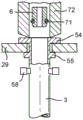
In the example shown in fig. 1 to 3, the cover 31 comprises a duct 31A which ensures communication of the nozzle 6 (extending horizontally in the example shown) with the steam channel of the froth wand in the operating position. However, it will be clear to the skilled person that the nozzles 6 may also be oriented vertically, for example. Such examples are disclosed in, for example, fig. 11A to 11D. In these examples shown in fig. 11A to 11D, the steam nozzle 6 is movably mounted in the device 2 to heat and froth the beverage. As shown in fig. 11D, the steam nozzle 44 is further dimensioned such that it can be received in the steam channel 25 of the froth wand 3. The steam nozzle 6 comprises a seal 71 for sealing against the inner surface of the tubular wall, thereby closing the steam channel. As shown in fig. 11, the steam nozzle 44 is movably arranged within a guide pipe 72, which is also movably mounted. The guide tube 72 is first lowered (either as part of or as an alternative to the cover) to seal the upper flange 54 of the froth wand and provide a grip in addition to that achieved by the gripping means 58 (fig. 11C). Thereafter, as shown in fig. 11D, the steam nozzle 6 is lowered into the steam channel of the froth wand, after which steam may be supplied to and passed through the steam nozzle and the steam channel.
A first example of a scheme of an example of a system is schematically shown in fig. 12, in which the interconnections between the constituent components are schematically shown. The means of the system for heating and frothing a beverage comprise a controller 73 operatively connected to the steamer 4 to control the operation of the steamer. Further, the controller 73 is operatively connected to the air pump to control operation of the air pump, and operatively connected to the cold water pump 10 to control operation of the cold water pump, and operatively connected to the valve 43 to position the valve in the respective connection position. In the case of a solenoid-operated froth wand ejector, the controller 73 is also operatively connected to the froth wand ejector to activate or deactivate the froth wand ejector. The system also includes the following shelving components: one-way valve 74, air flow restrictor 75, duckbill valve 76, additional thermal block 77 and vapor delivery valve 78, water flow meter 79, vapor vent valve 80, condenser 81 and vapor injection valve 82. In the second scheme example shown in fig. 13, additionally, the steam pump 83 and the pressure regulator 84 are closed in the manner shown.
Both systems shown in fig. 12 and 13 further comprise a froth wand holder detector 85 to detect whether the froth wand holder 19 is positioned in the operating position. The froth wand holder detector 85 is operatively connected to the controller 73 to provide a signal to the controller 73 indicating whether the froth wand holder 19 is positioned in the operating position. The controller 73 is then arranged for deactivating the (electromagnetically actuatable) froth wand ejector when the signal received from the froth wand holder detector 85 indicates that the froth wand holder 19 is in the operative position. The froth wand holder detector 85 is further arranged for detecting whether the froth wand holder 19 is positioned in the froth wand insertion position and may provide a signal to the controller 73 indicating whether the froth wand holder 19 is positioned in the froth wand insertion operative position. The controller 73 is then arranged to activate the froth wand ejector when the signal received from the froth wand holder detector 85 indicates that the froth wand holder is in the froth wand insertion position and the controller 73 has deactivated the steamer 4 within a predetermined time period before receiving the signal from the froth wand holder detector 85.
The controller 73 is arranged for automatically deactivating components operatively connected to said controller when a signal from the froth wand holder detector 85 indicates that the froth wand holder 19 is in the froth wand insertion position and/or for activating components operatively connected to said controller only when a signal from the froth wand holder detector 85 indicates that the froth wand holder is in the operative position.
In the version of the system shown in fig. 12 and 13, the device further comprises a froth wand presence detector 86 for detecting whether a froth wand 3 is held in the froth wand holder 19. A froth wand presence detector 86 is operatively connected to the controller 73 to provide a froth wand presence signal to the controller indicating whether the froth wand 3 is held in the froth wand holder 19. The controller 73 is then arranged for controlling the components operatively connected to said controller at least in dependence of the froth wand presence signal.
In the version of the system shown in fig. 12 and 13, the system, and in particular the device, further comprises a foam temperature sensor 87 to sense the temperature of the foam 28A in the cup 27. The temperature sensor 87 is operatively connected to the controller 73 to provide a signal indicative of the measured foam temperature to the controller. The foam temperature sensor includes at least one microphone (see fig. 14) that may be positioned above the cup 27 (87A), alongside the cup 27 and above the upper edge 27A of the cup 27 (87B), or alongside the cup and below the upper edge 27A of the cup 27 (87C). Measuring the temperature of the foam 28A then includes the steps of recording the sound from the foam 28A and deriving the temperature from the recorded sound by means of a suitable algorithm stored in the controller 73. Based on the measured temperature, the controller 73 may then decide whether to deactivate the steamer 4. Thus, the controller 73 controls the methods of heating, frothing, and preparing the beverage based on the information collected by the respective sensors 79, 85, 86 and 87.
In the following embodiments of the froth wand according to the invention it is shown that the froth wand comprises a container for containing a beverage base material. For example, the present invention will be described with Roast and Ground Coffee (RGC) as the beverage base material. However, the invention is not limited to roast and ground coffee, and the container of the froth wand according to the invention may contain other beverage base materials or food substances including, but not limited to, tea, herbs, soup, liquid beverages or food concentrates, powdered beverages or food concentrates, syrups, mixtures (powder or liquid concentrates), juices, chocolate drinks. Furthermore, water will be described as the extraction medium, but it will be clear that, depending on the base material, further extraction media, such as milk, may be used.
Fig. 15A and 15B schematically illustrate a first embodiment of a froth wand 101 for containing an RGC. The froth wand 101 comprises a base body 102 and a cover 103 (fig. 15C). The base body 102 is molded from PLA and includes an RGC chamber 104 defined by a chamber bottom 105 and a chamber wall 106 at the periphery of the chamber bottom 105. Although in the illustrated embodiment the wall has a circular circumference, in other embodiments the wall may have other shapes, such as a polygon or an ellipse. The chamber 104 of the base body is open on the side opposite the chamber bottom 105 for receiving an amount of RGC, preferably equal to the amount of coffee served in a single serving.
The chamber wall 106 has a sealing surface 107 at its free end opposite the chamber bottom 105, so that the cover 103 can be attached to the sealing surface 107 of the chamber wall 106 to close the RGC chamber 104.
The froth wand 101 further comprises an intake opening 108 for drawing water into the RGC chamber 104, which is formed by a pierceable water intake portion 108 provided in the chamber bottom 105. Furthermore, the froth wand 101 comprises a dispensing opening 109 for dispensing the coffee beverage from the RGC chamber 104 provided in the sealing surface 107 of the chamber wall 106.
The tubular wall of the froth wand forms an elongated handle 110 extending in a direction having a radial component outwards from the beverage base material chamber 104. The elongated handle 110 is integral with the base body 102 and includes a handle bottom 111 and a handle sealing flange 112. The handle 110 is provided with an outlet channel 113 extending from an upstream channel inlet 114 communicating with the dispensing opening 109 to a downstream channel outlet 115 provided at the free end of the handle 110. The handle sealing flange 112 is flush with the sealing surface 107 of the chamber wall 106, so that the cover 103 may also be attached to the sealing flange 112 of the handle 110 to close the outlet passage 113 in a direction opposite the handle bottom 111. As can be seen in fig. 15D, the sealing flange 112 of the handle 110 surrounds the channel outlet 113 such that when the cover 103 is attached to the sealing flange 112, the channel outlet 113 is completely closed even at the location of the channel outlet 115 (see fig. 15C). In order to open the channel outlet 115 by means of the pressure generated by the beverage dispensed through the outlet channel 113, the cover 103 is weakened at the location 116 of the channel outlet.
In the embodiment shown in fig. 15, the height of the chamber wall 106 is about five times the height of the elongated handle 110. This enables a sufficient amount of RGC to be received within the chamber 104 without excessive use of material while ensuring ease of handling. It should be appreciated that in other embodiments, the height ratio may be at least four or at least six, depending on the amount of RGC to be contained within the chamber 104, among other factors.
The upstream channel inlet 114 communicates with the dispensing opening 109 via a peripheral dispensing channel 117 provided in the sealing surface 107 of the chamber wall 106 to obtain a compact froth wand 101. The chamber bottom 105 is also provided with a pierceable extraction medium bypass suction portion 118 leading to the upstream channel inlet 114 of the outlet channel 113 of the handle 110 via an extraction medium bypass duct 119 in the chamber wall 106 discharging into the peripheral distribution channel 117. By using the extraction medium bypass 118, 119, a more consistent beverage output from the froth wand 101 can be obtained, and the intensity of the prepared beverage can be adjusted via said extraction medium bypass.
In the embodiment of the froth wand 101 shown in fig. 15A-F, the chamber bottom 105 is further provided with a pierceable steam inlet portion 120 leading via a steam inlet tube 121 in the chamber wall 106 to the upstream steam channel inlet 22 of the steam outlet channel 23 provided in the handle 110. The steam outlet channel 123 terminates in a downstream steam channel outlet provided at the free end of the handle 110, which in the embodiment shown coincides with the outlet 115. This is achieved by the outlet channel 113 discharging into the steam channel 123 at a position 125 at a distance from the free end of the handle 110. In other embodiments of the froth wand (not shown), the outlet of the steam channel 123 and the outlet of the outlet channel 113 may be separate from each other.
As can be seen in fig. 15C, the cover 103 also closes the steam channel 123 in a direction opposite to the handle bottom 111. In this way, the froth wand 101 itself can be used to supply steam, for example to fresh milk poured into a cup, to prepare a dairy foam. An air inlet slot 124 is provided in the handle bottom 111 leading to a steam channel 123. The air inlet slots 124 allow air to be drawn into the steam passage 123 as the steam passes through the steam passage 123 to provide a more consistent flow of steam through the steam passage 123.
A pierceable aroma vent portion 126 is provided in the chamber bottom 104 for allowing aroma to escape from the froth wand 101 after being pierced during beverage extraction. The cover 103 is at least partially transparent at a position 127 opposite the bottom of the chamber so that, for example, a user can pay close attention to the extraction process.
The handle 110 is provided with indicia 128 to indicate the lowest level of milk to be combined with the beverage, and may be surrounded by a manually removable paper sleeve (not shown) which is removed prior to use. The outer surface of the chamber bottom 105 of the froth wand 101 may be provided with a manually removable sealing membrane which is removed prior to use.
For example, a froth wand that does not require the use of steam to froth milk or in case the user does not wish to use steam, the base body 102 may be provided with a tear line 129 between the beverage base material chamber 104 and the handle 110 so that the handle 110 may be manually removed.
In fig. 15G, a second embodiment of a froth wand 101 according to the invention is partly shown. The froth wand 101 according to this second embodiment differs from the froth wand shown in fig. 15A to 15F in that it comprises an identifier 130 in the form of a depression in the chamber bottom 104, which identifier, when read by a reader in the device for preparing a beverage, provides data, e.g. relating to the type of RGC contained in the container, which data can be used to control the operation of the beverage preparation device for preparing a beverage in an optimal default manner, e.g. by adjusting the temperature and amount of hot water to be supplied into the beverage base material chamber and/or the temperature and duration of supplying steam to an amount of milk poured into the cup, depending on the read data.
In fig. 16 an automatic beverage preparation device 131 with a froth wand holder 131a to which a froth wand with a container of the present invention can be connected for preparing a beverage is schematically shown in perspective. In fig. 17A beverage preparation system is shown, wherein the froth wand 101 is connected in an operative position to the device 131 while milk as an additional ingredient is poured into a cup 132. The system of fig. 17A is schematically illustrated in cross-section in fig. 17B.
The automatic beverage preparation device 131 comprises a water supply 133 for supplying water into the RGC chamber 104 of the froth wand 101, so the device 131 itself may be free of a brewing chamber. The water supply means 133 comprises a horizontal support surface 134 and a water supply nozzle 135, against which the froth wand 101 can be pushed such that the water supply nozzle 135 penetrates the pierceable water intake portion, and the froth wand holder 131a is arranged such that the froth wand 101 is removably connected to the device 131. The froth wand 101 is connected to the automatic beverage preparation apparatus 131 such that the elongated handle 110 is positioned at least substantially vertically with the channel outlet 115 pointing downwards into the cup 132 for dispensing the coffee beverage from the RGC chamber 104 in a substantially vertical direction. The device 131 is further provided with: a water bypass supply 136 having a water bypass supply nozzle 137 that pierces the pierceable water bypass intake portion upon connection of the froth wand 101 to the automatic beverage preparation apparatus 131; and a steam supply device 138 having a steam conduit 138a connected to a steam supply nozzle 139 which pierces a pierceable steam inlet portion of the container when connecting the froth wand 101 to the automatic beverage preparation apparatus 131. The water required for the devices 133, 136 and 138 may be provided by a removable water reservoir 140 in communication with the water holders 141, 141', 141 "of the devices 133, 136 and 138, respectively.
As shown in fig. 16, the automatic beverage preparation apparatus 131 further includes an aroma vent piercing member 142 that pierces the pierceable aroma vent portion upon connecting the container to the automatic beverage preparation apparatus 131. In this way, the aroma generated during the preparation of the beverage by extraction can escape through the aroma vent portion, thereby providing the user with an increased taste and smell.
A control device 143 is included in the apparatus 131 for controlling the operation of the water and steam supply devices 133, 136, 138. The control means 143 and/or the device 131 may be switched on by means of, for example, an on/off switch 144 at the top of the device 131, but in order to ensure a repeatable and safe use of the device 131, the beverage preparation system is arranged for enabling operation by means of the control means 143 only after the froth wand 101 has been connected to the froth wand holder 131a of the automatic beverage preparation device 131. Such a connection may be established, for example, by means of the detectors 145, 146. In the example shown in fig. 17, the device 131 is arranged such that the nozzles 135, 137 and 139 and the fragrance vent 142 are displaceably mounted between an upper connecting position CP shown in solid lines in fig. 17B and a lower activating position AP shown in dashed lines in fig. 17B. The device 131 comprises a sensor 147 able to determine whether the nozzle is in the upper connection position CP or in the lower activation position AP and to send a signal to the control means 143 indicating the presence of the nozzle. In this way, the beverage preparation system may be arranged for enabling operation by means of the control device 143 only when the nozzle is in the activated position.
The automatic beverage preparation device 131 comprises a reader for reading data from the identifier 130 of the froth wand 101, which reader is formed by the detectors 145, 146 in this example. The readers 145, 146 provide signals indicative of the read identifiers to the control means 143, which may control the operation of the automatic beverage preparation apparatus 131 in accordance with said read data. In particular, the control device 143 may comprise a memory (not shown) containing processing profiles formulated for a specific type of roast and ground coffee. Each of these processing profiles may instruct the control means 143 to control the supplying means 133, 136 and 138 to perform, in use, a respective default process on the particular type of roasted ground coffee of the processing profile selected when reading the identifier 130. In this way, the amount and temperature of the hot water to be supplied to the chamber 104 can be set automatically by the control device 143, for example, when reading the identifier. Further, instead of or in addition to the on/off switch 144, the device 131 may include a user control panel in which the user may set his or her own process profiles or preferences that overrule the process profiles stored in the memory of the control apparatus.
The beverage preparation device as shown in fig. 17 comprises a beverage temperature sensor 150 to sense the temperature of the beverage dispensed to or present in the cup 149. The temperature sensor 150 is operatively connected to the control means to provide a signal indicative of the measured temperature of the beverage to the control means. The control means 143 may be arranged for controlling the beverage preparation device based on a signal indicative of the measured beverage temperature. In particular, the supply of steam may be controlled based on the measured temperature. In the specific example, the beverage temperature sensor 150 comprises at least one microphone 150A, which in the example shown is positioned above the cup.
In fig. 17B, the automatic beverage preparation device 131 is shown to comprise a milk quantity detector 148, in this example a weighing scale for detecting the amount of milk present in a cup 149. The milk quantity detector 148 provides a signal indicative of the detected quantity to the control device 143. Then, the control device 143 may control the operation of the steam supply device 138 according to the amount of milk in the cup 149.
A third embodiment of a froth wand according to the invention (hereinafter referred to as third froth wand) is shown in fig. 18A to 18F, parts of the third froth wand that are similar to the first and second embodiments being indicated with the same reference numerals.
The third froth wand 101 comprises a base body 102 and a cover 103 (fig. 18E). The base body 102 is molded from PLA and includes an RGC chamber 104 defined by a chamber bottom 105 and a chamber wall 106 at the periphery of the chamber bottom 105. Although in the illustrated embodiment the wall has a circular circumference, in other embodiments the wall may have other shapes, such as a polygon or an ellipse. The chamber 104 of the base body is open on the side located opposite the chamber bottom 105 for receiving a quantity of RGC, preferably equal to the quantity of a single coffee.
The chamber wall 106 has a sealing surface 107 at its free end opposite the chamber bottom 105, so that the cover 103 can be attached to the sealing surface 107 of the chamber wall 106 to close the RGC chamber 104. The cover 103 is in this embodiment formed by a perforated membrane or porous filter 103A and a cover element 103B. The cover element 103B is dome-shaped above the RGC chamber 104, while the membrane or porous filter 103A is flat, thereby forming an additional chamber 104A in which additional beverage base material, preferably different from roast and ground coffee in the chamber 104, can be accommodated.
The froth wand 101 further comprises an intake opening 108 for drawing water into the RGC chamber 104, which is formed by a pierceable water intake portion 108 provided in the chamber bottom 105. The third froth wand 101 further comprises an extraction medium inlet pipe 108A extending from the pierceable extraction medium intake portion 108 into the beverage base material chamber, preferably up to the perforated membrane or porous filter 103A. In this way, the extraction medium is provided to the additional beverage base material and then flows to the RGC in the chamber 104 via the perforated membrane or porous filter. Furthermore, the froth wand 101 comprises a dispensing hole 109 in the chamber wall 106 for dispensing the coffee beverage from the RGC chamber 104. A grill G and filter sheet F are provided in front of the distribution apertures 109 in the chamber 104 to prevent clogging of the apertures 109.
The elongated handle 110 extends in a direction having a radial component outward from the beverage base material chamber 104. The elongated handle 110 is integral with the base body 102 and includes a handle bottom 111 and a handle sealing flange 112A, B. The handle 110 is provided with an outlet channel 113 (see also fig. 18D1) extending from an upstream channel inlet 114 communicating with the dispensing opening 109 to a downstream channel outlet 115 provided at the free end of the handle 110. The handle sealing flange 112 is flush with the sealing surface 107 of the chamber wall 106, so that the cover 103 may also be attached to the sealing flange 112 of the handle 110 to close the outlet passage 113 in a direction opposite the handle bottom 111. As can be seen in fig. 18F, the sealing flange 112 of the handle 110 covers the outlet passage 113. The upstream channel inlet 114 communicates directly with the dispensing orifice 109 to obtain a compact froth wand 101.
In the embodiment of the third froth wand 101 shown in fig. 18A-F, the chamber bottom 105 is further provided with a pierceable steam inlet portion 120 leading via a steam inlet tube 121 to an upstream steam channel inlet 122 of a steam outlet channel 123 positioned below the outlet channel 113, both being provided in the handle 110. The steam outlet channel 123 terminates in a downstream steam channel outlet SO provided at the free end of the handle 110.
As can be seen in fig. 18E and 18F, cover part 103C also closes steam channel 123 in the direction opposite to handle bottom 111. In this way, the froth wand 101 itself can be used to supply steam, for example to fresh milk poured into a cup, to prepare a dairy foam.
A fourth embodiment of a froth wand with a container according to the invention (hereinafter referred to as fourth froth wand) is shown in fig. 19A to 19E, parts of the fourth froth wand that are similar to the first, second and third embodiments being indicated with the same reference numerals.
The fourth froth wand 101 comprises a base body 102 and a cover 103 comprising a disc shaped part 103D and an elongated part 103E. The base body 102 is molded from PLA and includes an RGC chamber 104 defined by a chamber bottom 105 and a chamber wall 106 at the periphery of the chamber bottom 105. Although in the illustrated embodiment the wall has a circular circumference, in other embodiments the wall may have other shapes, such as a polygon or an ellipse. The chamber 104 of the base body is open on the side opposite the chamber bottom 105 to receive an amount of RGC, preferably equal to the amount of coffee served in a single serving.
The chamber wall 106 has a sealing surface 107 at its free end opposite the chamber bottom 105, so that a disc-shaped cover member 103D can be attached to the sealing surface 107 of the chamber wall 106 to close the RGC chamber 104.
The fourth froth wand 101 also includes an intake opening 108 for drawing water into the RGC chamber 104, which is formed by a pierceable water intake portion 108 provided in the chamber bottom 105. The fourth froth wand 101 further comprises an extraction medium inlet pipe 108A extending from the pierceable extraction medium intake portion 108 into the beverage base material chamber, preferably up to half the height of the chamber 104. In this way, the extraction medium is provided into the additional beverage base material for correct extraction. Furthermore, the fourth froth wand 101 comprises a dispensing hole 109 in the chamber wall 106 for dispensing the coffee beverage from the RGC chamber 104. A grill G and filter sheet F are provided in front of the distribution apertures 109 in the chamber 104 to prevent clogging of the apertures 109.
The tubular wall of the fourth froth wand also forms an elongated handle 110 extending in a direction having a radial component outwards from the beverage base material chamber 104. The elongated handle 110 is integral with the base body 102 and includes a handle bottom 111 and a handle sealing flange formed by a cover member 103E. The handle 110 is provided with an outlet channel 113 extending from an upstream channel inlet 114 communicating with the dispensing opening 109 to a downstream channel outlet 115 provided at the free end of the handle 110. The handle sealing flange 112 is flush with the sealing surface 107 of the chamber wall 106, so that the cover 103 may also be attached to the sealing flange 112 of the handle 110 to close the outlet passage 113 in a direction opposite the handle bottom 111. The upstream channel inlet 114 communicates directly with the distribution holes 109 to obtain a compact fourth froth wand 101.
In the embodiment of the fourth froth wand 101 shown in fig. 19A-E, the chamber bottom 105 is further provided with a pierceable steam inlet portion 120 leading via a steam inlet tube 121 to an upstream steam channel inlet 122 of a steam outlet channel 123 positioned adjacent to the outlet channel 113, the steam outlet channel and the outlet channel being provided in the handle 110. The steam outlet channel 123 terminates in a downstream steam channel outlet SO disposed proximate the free end of the handle 110.
Claims (47)
1. A froth wand comprising a tubular wall having a steam inlet end comprising a steam inlet, a steam outlet end comprising a steam outlet separate from the steam inlet, and a steam channel extending between the steam inlet and the steam outlet, wherein the froth wand is a disposable froth wand, wherein the froth wand is made of a material having a low thermal mass, and wherein the disposable froth wand is made of a biodegradable material.
2. A froth wand according to claim 1, wherein the steam outlet extends radially through the tubular wall.
3. A froth wand according to claim 1, wherein the steam outlet is arranged at a free end of the froth wand extending in a longitudinal direction.
4. A froth wand according to any one of the preceding claims, wherein the steam outlet is a circular opening having a diameter between 1.0mm and 2.0 mm.
5. A froth wand according to any one of the claims 1 to 3, wherein the steam outlet comprises a plurality of steam outlet openings.
6. A froth wand according to claim 3, wherein the froth wand comprises a porous element adjacent to or in the steam outlet.
7. A froth wand according to any one of the claims 1 to 3, wherein the steam channel has a diameter of between 4mm and 10 mm.
8. A froth wand according to any one of the claims 1 to 3, wherein the tubular wall of the froth wand has a thickness of between 0.4mm and 0.6 mm.
9. A froth wand according to any one of the claims 1 to 3, wherein the froth wand is made of a material having a low thermal mass in the range of 1 to 20 grams.
10. A froth wand according to any one of the claims 1 to 3, wherein the length of the disposable froth wand is between 100mm and 120 mm.
11. A froth wand according to any one of the claims 1 to 3, wherein the froth wand comprises a blade at the steam outlet end.
12. A froth wand according to claim 11, wherein the blade is shaped asymmetrically with respect to a longitudinal axis of the tubular wall.
13. A froth wand according to claim 11, wherein the blade is shaped symmetrically with respect to a longitudinal axis of the tubular wall.
14. A froth wand according to any one of the claims 1 to 3, wherein the froth wand comprises a grip at the steam inlet end.
15. A froth wand according to claim 14, wherein the grip is shaped asymmetrically with respect to a longitudinal axis of the tubular wall.
16. A froth wand according to claim 14, wherein the grip is shaped symmetrically with respect to a longitudinal axis of the tubular wall.
17. A froth wand according to any one of the claims 1 to 3, wherein the froth wand comprises an upper flange at the steam inlet end.
18. A froth wand according to claim 17, wherein the upper flange has a flat end face.
19. A froth wand according to claim 17, wherein the froth wand comprises a holding flange spaced apart from an upper flange.
20. A froth wand according to any one of the claims 1 to 3, wherein an outer diameter of the tubular wall increases from the steam outlet end towards the steam inlet end.
21. A froth wand according to any one of the claims 1 to 3, wherein the tubular wall comprises a portion extending from the steam inlet end, the portion having a reduced outer diameter.
22. A froth wand according to any one of the claims 1 to 3, wherein the tubular wall of the froth wand comprises air openings, preferably shaped as slots extending parallel to a longitudinal axis of the tubular wall.
23. A froth wand according to any one of the claims 1 to 3, wherein the tubular wall of the froth wand comprises an air opening, wherein the air opening comprises one or more holes, and wherein at least one or each of the holes is shaped as a slot extending parallel to a longitudinal axis of the tubular wall.
24. A froth wand according to any one of the claims 1 to 3, wherein the froth wand comprises a circulation channel provided on the tubular wall near the steam outlet end of the froth wand, the circulation channel having a suction opening and a separate outlet opening, the outlet opening being positioned adjacent to the steam outlet, the circulation channel preferably being substantially parallel to the steam channel of the froth wand.
25. A froth wand according to any one of the claims 1 to 3, wherein the froth wand comprises a filling indicator mark.
26. A froth wand according to any one of the claims 1 to 3, wherein the froth wand comprises a container for containing a beverage base material, the container comprising a base body and a cover, the base body comprising a beverage base material chamber, the beverage base material chamber being defined by a chamber bottom and a chamber wall at a periphery of the chamber bottom, the chamber of the base body being open at a side opposite the chamber bottom, the chamber wall being provided with a sealing surface at a free end thereof opposite the chamber bottom, the cover being attached to the sealing surface of the chamber wall for closing the beverage base material chamber, the container comprising an intake opening for taking in an extraction medium into the beverage base material chamber and a dispensing opening for dispensing a beverage from the beverage base material chamber.
27. A froth wand according to claim 26, wherein the tubular wall forms an elongated handle extending in a direction having a radial component outwards from the beverage base material chamber, the elongated handle being integral with the base body and comprising a handle bottom and a handle sealing flange flush with the sealing surface of the chamber wall, the handle being provided with an outlet channel extending from an upstream channel inlet communicating with the dispensing opening to a downstream channel outlet provided at the free end of the handle, the cover further being attached to the sealing flange of the handle to close the outlet channel in a direction opposite the handle bottom.
28. A froth wand according to claim 27, wherein the height of the chamber wall is at least four times the height of the elongated handle.
29. A froth wand according to claim 27 or 28, wherein the sealing flange of the handle surrounds the channel outlet, wherein the cover is attached to the sealing flange to close the channel outlet, and wherein the cover is weakened at the location of the channel outlet to be opened by beverage dispensed through the outlet channel.
30. A froth wand according to claim 26, wherein the suction opening for sucking extraction medium into the beverage base material chamber is formed by a pierceable extraction medium suction portion provided in a bottom of the chamber.
31. A froth wand according to claim 30, wherein the container further comprises an extraction medium inlet tube extending from the pierceable extraction medium intake portion into the beverage base material chamber.
32. A froth wand according to claim 27, wherein the dispensing opening for dispensing beverage from the beverage base material chamber is provided in the sealing surface of the chamber wall.
33. A froth wand according to claim 32, wherein the upstream channel inlet communicates with the dispensing opening via a peripheral dispensing channel provided in the sealing surface of the chamber wall.
34. A froth wand according to claim 26, wherein the dispensing opening for dispensing beverage from the beverage base material chamber is provided by a dispensing hole in the chamber wall.
35. A froth wand according to claim 33, wherein the chamber bottom is provided with a pierceable extraction medium bypass intake portion, and wherein the chamber wall is provided with an extraction medium bypass duct extending from the pierceable extraction medium bypass intake portion to the upstream channel inlet of the outlet channel of the handle.
36. A froth wand according to claim 35, wherein the extraction medium bypass pipe discharges into the peripheral dispensing channel provided in the sealing surface of the chamber wall.
37. A froth wand according to claim 27, wherein the steam inlet is provided in the container, the steam inlet having a pierceable steam inlet portion, wherein the steam channel extends in the handle from an upstream steam channel inlet to a downstream steam channel outlet provided at the free end of the handle, wherein the container is further provided with a steam inlet tube extending from the pierceable steam inlet portion to the upstream steam channel inlet of the steam channel outlet of the handle, and wherein the cover is further attached to the sealing flange of the handle to close the steam channel in a direction opposite to the handle bottom.
38. A froth wand according to claim 37, wherein the outlet channel discharges into the steam channel at a distance from the free end of the handle.
39. A froth wand container according to claim 26, wherein the chamber bottom is provided with a pierceable aroma vent portion.
40. A froth wand according to claim 26, wherein the cover is at least partially transparent.
41. A froth wand according to claim 26, wherein an outer surface of the chamber bottom is provided with a manually removable sealing film or cover.
42. A froth wand according to claim 27, wherein the base body is provided with a tear line between the beverage base material chamber and the handle for manually removing the handle.
43. A froth wand according to claim 26, wherein the container is provided with an identifier, the identifier being provided with data.
44. A froth wand according to claim 43, wherein the identifier comprises a protrusion and/or a depression in the chamber bottom.
45. A froth wand according to claim 26, wherein the base body is molded from a bio-plastic such as pla (tbc).
46. A froth wand according to claim 26, wherein the container contains an amount of roast and ground coffee for a single serving.
47. A froth wand according to any one of the claims 1 to 3, wherein the froth wand is provided with a manually removable paper sleeve at least surrounding the tubular wall.
Applications Claiming Priority (3)
| Application Number | Priority Date | Filing Date | Title |
|---|---|---|---|
| NL2015070 | 2015-07-01 | ||
| NL2015070A NL2015070B1 (en) | 2015-07-01 | 2015-07-01 | A froth wand. |
| PCT/NL2016/050466 WO2017003290A1 (en) | 2015-07-01 | 2016-06-30 | A froth wand. |
Publications (2)
| Publication Number | Publication Date |
|---|---|
| CN107708506A CN107708506A (en) | 2018-02-16 |
| CN107708506B true CN107708506B (en) | 2021-04-16 |
Family
ID=55077574
Family Applications (1)
| Application Number | Title | Priority Date | Filing Date |
|---|---|---|---|
| CN201680039386.4A Active CN107708506B (en) | 2015-07-01 | 2016-06-30 | Foaming stick |
Country Status (15)
| Country | Link |
|---|---|
| US (1) | US10806294B2 (en) |
| EP (1) | EP3316747B1 (en) |
| JP (1) | JP6962824B2 (en) |
| KR (1) | KR20180025910A (en) |
| CN (1) | CN107708506B (en) |
| AU (1) | AU2016286168B2 (en) |
| BR (1) | BR112017028410B1 (en) |
| CA (1) | CA2990768A1 (en) |
| DK (1) | DK3316747T3 (en) |
| ES (1) | ES2792948T3 (en) |
| IL (1) | IL256669B (en) |
| NL (1) | NL2015070B1 (en) |
| PL (1) | PL3316747T3 (en) |
| RU (1) | RU2710414C2 (en) |
| WO (1) | WO2017003290A1 (en) |
Families Citing this family (8)
| Publication number | Priority date | Publication date | Assignee | Title |
|---|---|---|---|---|
| NL2015068B1 (en) * | 2015-07-01 | 2017-01-30 | Douwe Egberts Bv | A system for heating and frothing a beverage, a device for heating and frothing a beverage suitable for being used in such a system, a froth wand suitable for being used in such a system and a method of preparing a beverage using such a system. |
| ITUA20162284A1 (en) * | 2016-04-04 | 2017-10-04 | Iacobucci Hf Aerospace S P A | Cappuccino |
| NL2017385B1 (en) * | 2016-08-29 | 2018-03-08 | Cramer Holding B V | STEAM INJECTION DEVICE, STEAM PIPE FOR USE WITH SUCH DEVICE AND METHOD FOR HEATING A FOODSTUFF WITH STEAM INJECTION |
| US11058250B2 (en) * | 2018-09-06 | 2021-07-13 | Starbucks Corporation | Apparatus for foaming a beverage |
| GB2580148B (en) * | 2018-12-21 | 2022-08-24 | Douwe Egberts Bv | Frothing container and method of creating a frothed beverage |
| GB2580183B (en) * | 2018-12-24 | 2022-11-30 | Douwe Egberts Bv | A system and method for heating and frothing a beverage |
| US20210068581A1 (en) * | 2019-09-05 | 2021-03-11 | B/E Aerospace, Inc. | Multi-Position Shuttle Valve Assembly for an Aircraft Brewing Apparatus |
| GB2590699B (en) * | 2019-12-24 | 2023-12-06 | Douwe Egberts Bv | Beverage preparation systems |
Citations (7)
| Publication number | Priority date | Publication date | Assignee | Title |
|---|---|---|---|---|
| WO2001088187A1 (en) * | 2000-05-19 | 2001-11-22 | Rancilio Macchine Per Caffe' S.P.A. | Device for heating and frothing a liquid, in particular milk |
| EP1597992A1 (en) * | 2004-05-19 | 2005-11-23 | MELITTA HAUSHALTSPRODUKTE GmbH & Co. Kommanditgesellschaft | Device for frothing a liquid |
| CN1846581A (en) * | 2005-04-13 | 2006-10-18 | 雀巢技术公司 | Replaceable nozzle for producing a frothed liquid |
| CN1897854A (en) * | 2003-12-22 | 2007-01-17 | 皇家飞利浦电子股份有限公司 | Liquid cartridge for use in a beverage system |
| WO2008049162A1 (en) * | 2006-10-24 | 2008-05-02 | Brando International Limited | Protective sheath |
| WO2010121299A1 (en) * | 2009-04-20 | 2010-10-28 | Sunbeam Corporation Limited | Steam wand |
| CN104507370A (en) * | 2012-03-26 | 2015-04-08 | Be航天公司 | Froth wand for espresso maker |
Family Cites Families (23)
| Publication number | Priority date | Publication date | Assignee | Title |
|---|---|---|---|---|
| US1836931A (en) | 1930-02-17 | 1931-12-15 | W E Long Co | Process of imparting coffee aroma to soluble coffee |
| US3823241A (en) | 1970-09-21 | 1974-07-09 | Procter & Gamble | Cryogenic aromatization of instant coffee |
| US3769032A (en) | 1971-10-15 | 1973-10-30 | Procter & Gamble | Aroma-enriched coffee products and process |
| US4517120A (en) | 1983-10-19 | 1985-05-14 | Nestec, S.A. | Coffee oil treatment |
| ATE35499T1 (en) | 1983-12-06 | 1988-07-15 | Nestle Sa | COFFEE AUTOMATION. |
| ES2038399T3 (en) | 1988-07-13 | 1993-07-16 | Douwe Egberts Koninklijke Tabaksfabriek- Koffiebranderijen-Theehandel N.V. | PROCEDURE FOR PREPARING A GROUND ROASTED COFFEE EXTRACT. |
| CA2090169A1 (en) | 1992-03-12 | 1993-09-13 | Jerome F. Trumbetas | Colloidal roasted coffee as aromatizer |
| JP2001070447A (en) * | 1999-09-06 | 2001-03-21 | Shimadzu Corp | Needless syringe |
| GB2374856B (en) * | 2001-04-27 | 2004-11-03 | Mars Uk Ltd | Production of edible foams |
| US6786138B2 (en) * | 2002-01-16 | 2004-09-07 | Boyd Coffee Company | Device for preparing milk froth for cappuccino |
| ATE459278T1 (en) * | 2003-03-24 | 2010-03-15 | Nestec Sa | DEVICE FOR PUMPING A LIQUID FROM A PACKAGING OR CONTAINER |
| NL1030178C2 (en) | 2005-10-12 | 2007-04-13 | Sara Lee De Nv | Method for preparing a coffee extract, as well as the extract obtainable therefrom. |
| US20090266245A1 (en) * | 2005-11-29 | 2009-10-29 | Sanden Corporation | Liquid food heating apparatus & steam jet nozzle for liquid food heating apparatus |
| ITTO20060089U1 (en) * | 2006-06-12 | 2007-12-13 | Buzzi Srl | DEVICE FOR THE PREPARATION OF FOAMY HOT DRINKS, PARTICULARLY CAPPUCCINI AND SIMILAR |
| JP2012153894A (en) * | 2006-07-05 | 2012-08-16 | Mitsubishi Plastics Inc | Tubular molded item made from biodegradable resin |
| US8685477B2 (en) * | 2008-01-17 | 2014-04-01 | Enodis Corporation | Method for blending a beverage in a single serving cup |
| JP5393566B2 (en) * | 2010-03-30 | 2014-01-22 | 富士ケミカル株式会社 | Tubular molded product |
| EP3023361B1 (en) * | 2010-07-22 | 2018-12-26 | K-fee System GmbH | Portion capsule having an identifier |
| PT2433527E (en) * | 2010-09-28 | 2013-04-30 | Gruppo Cimbali Spa | Improved automatic milk frothing wand |
| EP2625962B1 (en) | 2010-10-05 | 2017-06-21 | Kao Corporation | Concentrated coffee composition |
| US20130149282A1 (en) * | 2011-12-09 | 2013-06-13 | David Christopher Marshall | Food-based utensils and storage containers and methods of making the same |
| GB2508352B (en) | 2012-11-28 | 2017-08-16 | Douwe Egberts Bv | Treating soluble coffee |
| AU2014370513B2 (en) | 2013-12-23 | 2018-07-05 | Koninklijke Douwe Egberts B.V. | Aroma-retaining soluble coffee |
-
2015
- 2015-07-01 NL NL2015070A patent/NL2015070B1/en active
-
2016
- 2016-06-30 CA CA2990768A patent/CA2990768A1/en active Pending
- 2016-06-30 WO PCT/NL2016/050466 patent/WO2017003290A1/en active Application Filing
- 2016-06-30 RU RU2018103747A patent/RU2710414C2/en active
- 2016-06-30 EP EP16745527.8A patent/EP3316747B1/en active Active
- 2016-06-30 JP JP2017568216A patent/JP6962824B2/en active Active
- 2016-06-30 BR BR112017028410-3A patent/BR112017028410B1/en active IP Right Grant
- 2016-06-30 KR KR1020187002828A patent/KR20180025910A/en active IP Right Grant
- 2016-06-30 ES ES16745527T patent/ES2792948T3/en active Active
- 2016-06-30 AU AU2016286168A patent/AU2016286168B2/en active Active
- 2016-06-30 PL PL16745527T patent/PL3316747T3/en unknown
- 2016-06-30 DK DK16745527.8T patent/DK3316747T3/en active
- 2016-06-30 CN CN201680039386.4A patent/CN107708506B/en active Active
-
2017
- 2017-12-27 US US15/855,354 patent/US10806294B2/en active Active
- 2017-12-31 IL IL256669A patent/IL256669B/en unknown
Patent Citations (7)
| Publication number | Priority date | Publication date | Assignee | Title |
|---|---|---|---|---|
| WO2001088187A1 (en) * | 2000-05-19 | 2001-11-22 | Rancilio Macchine Per Caffe' S.P.A. | Device for heating and frothing a liquid, in particular milk |
| CN1897854A (en) * | 2003-12-22 | 2007-01-17 | 皇家飞利浦电子股份有限公司 | Liquid cartridge for use in a beverage system |
| EP1597992A1 (en) * | 2004-05-19 | 2005-11-23 | MELITTA HAUSHALTSPRODUKTE GmbH & Co. Kommanditgesellschaft | Device for frothing a liquid |
| CN1846581A (en) * | 2005-04-13 | 2006-10-18 | 雀巢技术公司 | Replaceable nozzle for producing a frothed liquid |
| WO2008049162A1 (en) * | 2006-10-24 | 2008-05-02 | Brando International Limited | Protective sheath |
| WO2010121299A1 (en) * | 2009-04-20 | 2010-10-28 | Sunbeam Corporation Limited | Steam wand |
| CN104507370A (en) * | 2012-03-26 | 2015-04-08 | Be航天公司 | Froth wand for espresso maker |
Also Published As
| Publication number | Publication date |
|---|---|
| CN107708506A (en) | 2018-02-16 |
| ES2792948T3 (en) | 2020-11-12 |
| WO2017003290A1 (en) | 2017-01-05 |
| NL2015070B1 (en) | 2017-01-30 |
| US10806294B2 (en) | 2020-10-20 |
| KR20180025910A (en) | 2018-03-09 |
| IL256669B (en) | 2021-12-01 |
| DK3316747T3 (en) | 2020-05-18 |
| BR112017028410B1 (en) | 2022-07-05 |
| EP3316747A1 (en) | 2018-05-09 |
| BR112017028410A2 (en) | 2018-08-28 |
| RU2018103747A3 (en) | 2019-08-02 |
| JP2018519111A (en) | 2018-07-19 |
| PL3316747T3 (en) | 2020-08-10 |
| CA2990768A1 (en) | 2017-01-05 |
| AU2016286168A1 (en) | 2018-02-15 |
| JP6962824B2 (en) | 2021-11-05 |
| AU2016286168B2 (en) | 2021-07-01 |
| RU2710414C2 (en) | 2019-12-26 |
| NZ739104A (en) | 2023-11-24 |
| IL256669A (en) | 2018-02-28 |
| US20180310753A1 (en) | 2018-11-01 |
| RU2018103747A (en) | 2019-08-02 |
| EP3316747B1 (en) | 2020-02-26 |
Similar Documents
| Publication | Publication Date | Title |
|---|---|---|
| CN107708506B (en) | Foaming stick | |
| CN107735003B (en) | System for heating and frothing a beverage | |
| US11083323B2 (en) | Container for containing a beverage base material, a beverage preparation system including an automatic beverage preparation apparatus and such a container, an automatic beverage preparation apparatus for use in such a beverage preparation system and a method of preparing a beverage using such a beverage preparation system |
Legal Events
| Date | Code | Title | Description |
|---|---|---|---|
| PB01 | Publication | ||
| PB01 | Publication | ||
| SE01 | Entry into force of request for substantive examination | ||
| SE01 | Entry into force of request for substantive examination | ||
| GR01 | Patent grant | ||
| GR01 | Patent grant |