JP4335848B2 - Auto light control device - Google Patents
Auto light control device Download PDFInfo
- Publication number
- JP4335848B2 JP4335848B2 JP2005169390A JP2005169390A JP4335848B2 JP 4335848 B2 JP4335848 B2 JP 4335848B2 JP 2005169390 A JP2005169390 A JP 2005169390A JP 2005169390 A JP2005169390 A JP 2005169390A JP 4335848 B2 JP4335848 B2 JP 4335848B2
- Authority
- JP
- Japan
- Prior art keywords
- headlight
- light
- circuit
- small light
- output
- Prior art date
- Legal status (The legal status is an assumption and is not a legal conclusion. Google has not performed a legal analysis and makes no representation as to the accuracy of the status listed.)
- Active
Links
Images
Description
本発明は、車両周辺の照度を検出する照度センサの検出値を、スモールライト及びヘッドライトのそれぞれに対応して予め設定された基準値とそれぞれ比較することにより、スモールライト及びヘッドライトの点灯及び消灯を自動的に制御する制御手段を備えたオートライト制御装置に関する。 The present invention compares the detected value of the illuminance sensor that detects the illuminance around the vehicle with a reference value set in advance corresponding to each of the small light and the headlight, thereby enabling lighting of the small light and the headlight. The present invention relates to an auto light control device provided with a control means for automatically controlling turning off.
従来から、車のスモールライト及びヘッドライトを周囲の明るさに応じて自動点灯するオートライト制御装置が提案されている(例えば、特許文献1参照)。 2. Description of the Related Art Conventionally, there has been proposed an automatic light control device that automatically turns on a small light and a headlight of a car according to ambient brightness (see, for example, Patent Document 1).
このオートライト制御装置は、照度センサの検出値を基準値と比較し、その比較結果に基づいてスモールライトとヘッドライトの点灯と消灯を制御するオートライト制御装置のコンパレータ回路にメモリ回路を設け、そのメモリ回路に前記スモールライト及びヘッドライトの点灯と消灯とを行うライティングスイッチを接続し、そのライティングスイッチを操作した際に、その操作時点の照度センサの検出値をメモリ回路に記憶させ、その記憶した検出値を基準値としてスモールライト及びヘッドライトの点灯と消灯とを制御させるようになっている。これにより、点灯及び消灯の照度の設定をユーザが簡単に調整できるようになっている。 This auto light control device compares the detection value of the illuminance sensor with a reference value, and provides a memory circuit in the comparator circuit of the auto light control device that controls turning on and off of the small light and headlight based on the comparison result, A lighting switch for turning on and off the small light and headlight is connected to the memory circuit, and when the lighting switch is operated, the detection value of the illuminance sensor at the time of the operation is stored in the memory circuit, and the storage The small light and the headlight are controlled to be turned on and off using the detected value as a reference value. Thereby, the user can easily adjust the setting of the illuminance for turning on and off.
具体的に説明すると、ライティングスイッチは、ライトオフスイッチポジョンから、スモールライトスイッチポジション、ヘッドライトスイッチポジション、オートスイッチポジションまで順次切り換えられるようになっている。 More specifically, the lighting switch is sequentially switched from the light-off switch position to the small light switch position, the headlight switch position, and the auto switch position.
そして、スモールライトの点灯タイミングを設定するためには、ライティングスイッチをライトオフスイッチポジションからスモールライトスイッチポジションに切り換え、その状態を継続することにより、ユーザの所望するスモールライトの点灯タイミングが設定できるようになっている。また、ヘッドライトの点灯タイミングを設定するためには、ライティングスイッチをライトオフスイッチポジションからヘッドライトスイッチポジションに切り換え、その状態を継続することにより、ユーザの所望するヘッドライトの点灯タイミングが設定できるようになっている。
上記従来のオートライト制御装置によれば、スモールライト及びヘッドライトの点灯タイミングを設定する場合、ユーザは、ライティングスイッチを手動操作して、スモールライトを点灯し、またはヘッドライトを点灯する必要がある。いわゆる通常の手動操作によるライティング操作を行う必要がある。 According to the conventional auto light control device, when setting the lighting timing of the small light and the headlight, the user needs to manually operate the lighting switch to turn on the small light or turn on the headlight. . It is necessary to perform a so-called normal manual lighting operation.
ここで、例えばヘッドライトの点灯タイミングを設定した時点では、車のライトはスモールライトもヘッドライトも点灯した夜間走行状態となっていることから、ライティングスイッチをヘッドライトスイッチポジションからわざわざオートスイッチポジションに切り換えなくても、走行に何の支障もない。そのため、ユーザは、往々にしてヘッドライトスイッチポジションからオートスイッチポジションへの切り換えを忘れる場合がある。 Here, for example, when the lighting timing of the headlight is set, the car light is in the night driving state where both the small light and the headlight are lit, so the lighting switch is moved from the headlight switch position to the auto switch position. Even without switching, there is no problem in running. Therefore, the user often forgets to switch from the headlight switch position to the auto switch position.
この場合、オートライト制御は実行されないので、例えば夜間走行状態でトンネルを抜けた場合、ユーザはオートライト制御と勘違いして、ライトを消し忘れるといった不具合が発生する可能性がある。これは、スモールライト及びヘッドライトの点灯タイミングの設定を、ライティングスイッチの手動操作に連動させたことに起因している。 In this case, since the auto light control is not executed, for example, when the user exits the tunnel in the night driving state, there is a possibility that the user mistakes the auto light control and forgets to turn off the light. This is because the setting of the lighting timing of the small light and the headlight is linked to the manual operation of the lighting switch.
本発明はかかる問題点を解決すべく創案されたもので、その目的は、ボリューム調整という極めて簡単な構成で、ユーザによるスモールライト及びヘッドライトの点灯タイミングの調整を可能としたオートライト制御装置を提供することにある。 The present invention was devised to solve such problems, and an object of the present invention is to provide an auto light control device that enables the user to adjust the lighting timing of small lights and headlights with a very simple configuration of volume adjustment. It is to provide.
上記課題を解決するため、本発明のオートライト制御装置は、車両周辺の照度を検出する照度センサの検出値を、スモールライト及びヘッドライトのそれぞれに対応して予め設定された基準値とそれぞれ比較することにより、スモールライト及びヘッドライトの点灯及び消灯を自動的に制御する制御手段を備えたオートライト制御装置において、前記スモールライト及びヘッドライトの点灯時期を個別に調整可能な調整手段を備えており、該調整手段が前記基準値を変更可能なボリュームによって構成されてなり、
前記制御手段は、前記照度センサの検出値と前記基準値とを比較する第1の比較回路と、前記第1の比較回路の出力が遅延回路を介してコンパレータのマイナス側入力に接続され、プラス側入力に第2の基準値が与えられた第2の比較回路と、前記第2の比較回路の出力によって前記ライトの点灯及び消灯を制御する出力回路とを備え、
特に、前記スモールライトの出力回路と前記ヘッドライトの出力回路とが補償回路によって接続されており、前記補償回路は、ヘッドライトの点灯時には必ずスモールライトも点灯するように前記スモールライトの出力回路を制御することを特徴とする。
In order to solve the above problems, the auto light control device of the present invention compares the detection value of the illuminance sensor that detects the illuminance around the vehicle with a reference value set in advance corresponding to each of the small light and the headlight. In the auto light control device having a control means for automatically controlling the turning on and off of the small light and the headlight, the adjusting means capable of individually adjusting the lighting timing of the small light and the headlight is provided. And the adjusting means is constituted by a volume capable of changing the reference value ,
The control means includes a first comparison circuit that compares a detection value of the illuminance sensor and the reference value, and an output of the first comparison circuit is connected to a negative input of the comparator via a delay circuit, A second comparison circuit in which a second reference value is given to a side input; and an output circuit that controls turning on and off of the light by an output of the second comparison circuit;
In particular, the output circuit of the small light and the output circuit of the headlight are connected by a compensation circuit, and the compensation circuit is configured so that the small light is always turned on when the headlight is turned on. It is characterized by controlling .
ここで、前記制御手段は、具体的には、前記照度センサの検出値と前記基準値とを比較する第1の比較回路と、前記第1の比較回路の出力が遅延回路を介してコンパレータのマイナス側入力に接続され、プラス側入力に第2の基準値が与えられた第2の比較回路と、前記第2の比較回路の出力によって前記ライトの点灯及び消灯を制御する出力回路とを備えた構成とする。 Here, the control means specifically includes a first comparison circuit that compares a detection value of the illuminance sensor and the reference value, and an output of the first comparison circuit is output from a comparator via a delay circuit. A second comparison circuit connected to the negative side input and provided with a second reference value to the positive side input; and an output circuit for controlling lighting and extinction of the light by the output of the second comparison circuit. The configuration is as follows.
本発明によれば、ボリュームという簡単な構成により、ライティングスイッチとは切り離した状態で、ユーザによるスモールライト及びヘッドライトの点灯タイミングの調整を可能としたので、調整後のライトの消し忘れ等を確実に防止することができる。また、これにより車両照明における点灯時期の個人差を緩和し、夕刻時の安全性を確保することができる。 According to the present invention, the simple configuration of the volume enables the user to adjust the lighting timing of the small light and the headlight in a state separated from the lighting switch, so that it is possible to reliably forget to turn off the light after adjustment. Can be prevented. In addition, this makes it possible to alleviate individual differences in lighting timing in vehicle lighting and to ensure safety in the evening.
この場合、前記制御手段は、前記ボリュームによる調整に関わらず、ヘッドライトの点灯時にはスモールライトも点灯するように制御する。具体的には、前記スモールライトの出力回路と前記ヘッドライトの出力回路とが補償回路によって接続されており、前記補償回路は、ヘッドライトの点灯時には必ずスモールライトも点灯するように前記スモールライトの出力回路を制御する。これにより、ヘッドライトが点灯しているのに、スモールライトが点灯していないといった事態の発生を防止することができる。 In this case, the control means controls the small light to be turned on when the headlight is turned on, regardless of the adjustment by the volume. Specifically, the output circuit of the small light and the output circuit of the headlight are connected by a compensation circuit, and the compensation circuit of the small light is always turned on when the headlight is turned on. Control the output circuit. As a result, it is possible to prevent the occurrence of a situation where the small light is not lit while the headlight is lit.
また、前記制御手段は、前記検出値と前記基準値との比較結果である点灯信号が所定の時間以上継続したときに前記スモールライトまたは前記ヘッドライトを点灯するように構成してもよい。具体的には、前記遅延回路と前記第2の比較回路とが、前記第1の比較回路の出力信号が所定の時間以上継続したときに前記スモールライトまたは前記ヘッドライトを点灯させる遅延手段を構成している。これにより、例えば短い高架橋の下を短時間(例えば、2〜3秒程度)で通過したような場合等に、ヘッドライトが点灯直後に消灯するといった、いわゆるパッシング現象の発生を防止することが可能となる。 The control means may be configured to turn on the small light or the headlight when a lighting signal that is a comparison result between the detected value and the reference value continues for a predetermined time or longer. Specifically, the delay circuit and the second comparison circuit constitute delay means for turning on the small light or the headlight when the output signal of the first comparison circuit continues for a predetermined time or more. is doing. As a result, for example, when passing under a short viaduct in a short time (for example, about 2 to 3 seconds), it is possible to prevent the so-called passing phenomenon that the headlight is turned off immediately after turning on. It becomes.
また、前記制御手段は、前記スモールライトまたは前記ヘッドライトの点灯後の消灯タイミングに幅を持たせることによって、点灯後のライトの点滅を防止するように構成してもよい。具体的には、前記第2の比較回路の出力が帰還抵抗を介してプラス側入力に接続されたヒステリシス回路を備えている。このように、第2の比較回路の検知幅に幅を持たせることにより、例えばノイズ等の影響によってライト点灯直後やライト消灯直後のチャタリング現象の発生を防止することが可能となる。 Further, the control means may be configured to prevent blinking of the light after being turned on by giving a width to the turn-off timing after turning on the small light or the headlight. Specifically, a hysteresis circuit is provided in which the output of the second comparison circuit is connected to the plus side input via a feedback resistor. Thus, by providing a width to the detection width of the second comparison circuit, it is possible to prevent the occurrence of chattering immediately after the light is turned on or immediately after the light is turned off due to the influence of noise or the like.
さらに、前記制御手段は、前記スモールライトまたは前記ヘッドライトの点灯時間に応じて消灯時のタイミングを遅延するようにしてもよい。例えば、高架橋下を通過時とトンネル通過時とでは、車両照明の連続点灯時間が異なるので、このことを利用して、消灯時期の遅延効果を持たせ、より自然な滑らかな消灯制御が可能となる。具体的には、第2の比較回路にコンパレータを使用しているので、このコンパレータの特性により、消灯時の遅延効果を持たせることができる。 Further, the control means may delay the timing when the light is turned off according to the lighting time of the small light or the headlight. For example, the continuous lighting time of vehicle lighting differs between when passing under a viaduct and when passing through a tunnel, and this can be used to provide a delay effect of the turn-off time, enabling more natural and smooth turn-off control. Become. Specifically, since a comparator is used for the second comparison circuit, a delay effect at the time of extinction can be provided by the characteristics of the comparator.
本発明によれば、ボリュームという簡単な構成により、ライティングスイッチとは切り離した状態で、ユーザによるスモールライト及びヘッドライトの点灯タイミングの調整を可能としたので、調整後のライトの消し忘れ等を確実に防止することができる。また、これにより車両照明における点灯時期の個人差を緩和し、夕刻時の安全性を確保することができる。 According to the present invention, the simple configuration of the volume enables the user to adjust the lighting timing of the small light and the headlight in a state separated from the lighting switch, so that it is possible to reliably forget to turn off the light after adjustment. Can be prevented. In addition, this makes it possible to alleviate individual differences in lighting timing in vehicle lighting and to ensure safety in the evening.
以下、本発明の実施の形態について、図面を参照して説明する。 Embodiments of the present invention will be described below with reference to the drawings.
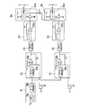
図1は、本実施形態のオートライト制御装置の全体構成を示す回路ブロック図である。 FIG. 1 is a circuit block diagram showing the overall configuration of the auto light control device of the present embodiment.
このオートライト制御装置は、大別すると、車両周辺の照度を検出するフォトダイオードからなる照度センサ11aと、ノイズ吸収用の第1の遅延回路11bとからなる入力回路11を備えており、その後の系が、スモールライトの制御系と、ヘッドライトの制御系とに分かれている。
The automatic light control device is roughly divided into an
すなわち、各制御系は、この入力回路11による照度センサ11aの検出電圧値と第1の基準電圧値とを比較する第1の比較回路21,31と、第1の比較回路21,31の出力が接続された第3の遅延回路22,32と、第3の遅延回路22,32の出力がコンパレータのマイナス側入力に接続され、プラス側入力に第2の基準値が与えられた第2の比較回路23,33と、第2の比較回路23,33の出力によってライトの点灯及び消灯を制御する出力回路24,34とを備えている。
That is, each control system compares the detection voltage value of the
まず、スモールライトの制御系について具体的に説明する。 First, the small light control system will be described in detail.
第1の比較回路21は、入力回路11からの検出電圧値V0が、第1の遅延回路11b及び第2の遅延回路21bを介して第1のコンパレータ21aのマイナス側入力に導かれており、プラス側入力には、スモールライト調整用のボリュームVR1を介して第1の基準電圧値Vref21が導かれている。また、第1のコンパレータ21aの出力は、第3の遅延回路22に接続されているとともに、帰還抵抗R1を介して、プラス側入力に接続されている。
In the
第2の比較回路23は、第3の遅延回路22の出力が第2のコンパレータ23aのマイナス側入力に導かれており、プラス側入力には、第2の基準電圧値Vref22が導かれている。また、第2のコンパレータ23aの出力は、出力回路24を構成するトランジスタQ1のベースに接続されているとともに、帰還抵抗R2を介して、プラス側入力に接続されている。
In the
出力回路24は、ベースがアース電位に接続された前記トランジスタQ1のエミッタにリレー回路24aが接続されている。そして、このリレー回路24aのオン、オフ制御により、スモールライトの点灯、消灯が制御されるようになっている。
In the
次に、ヘッドライトの制御系について具体的に説明する。 Next, a headlight control system will be described in detail.
第1の比較回路31は、入力回路11からの検出電圧値V0が、第1の遅延回路11b及び第2の遅延回路31bを介して第1のコンパレータ31aのマイナス側入力に導かれており、プラス側入力には、ヘッドライト調整用のボリュームVR2を介して第1の基準電圧値Vref31が導かれている。また、第1のコンパレータ31aの出力は、第3の遅延回路32に接続されているとともに、帰還抵抗R3を介して、プラス側入力に接続されている。
In the
第2の比較回路33は、第3の遅延回路32の出力が第2のコンパレータ33aのマイナス側入力に導かれており、プラス側入力には、第2の基準電圧値Vref32が導かれている。また、第2のコンパレータ33aの出力は、出力回路34を構成するトランジスタQ2のベースに接続されているとともに、帰還抵抗R4を介して、プラス側入力に接続されている。
In the
出力回路34は、ベースがアース電位に接続された前記トランジスタQ2のエミッタにリレー回路34aが接続されている。そして、このリレー回路34aのオン、オフ制御により、ヘッドライトの点灯、消灯が制御されるようになっている。
In the
すなわち、スモールライト制御系とヘッドライト制御系とは、抵抗値やコンデンサの容量値は若干異なるものの、回路構成自体は同様の構成となっている。 That is, the small light control system and the headlight control system have the same circuit configuration, although the resistance value and the capacitance value of the capacitor are slightly different.
上記構成によれば、ユーザがボリュームVR1を調整することで、スモールライト側の第1の基準電圧値Vref21を変更することができるので、スモールライトの点灯タイミングを調整することができる。同様に、ユーザがボリュームVR2を調整することで、ヘッドライト側の第1の基準電圧値Vref31を変更することができるので、ヘッドライトの点灯タイミングを調整することができる。 According to the above configuration, since the user can change the first reference voltage value Vref21 on the small light side by adjusting the volume VR1, the lighting timing of the small light can be adjusted. Similarly, since the user can change the first reference voltage value Vref31 on the headlight side by adjusting the volume VR2, the lighting timing of the headlight can be adjusted.
また、上記構成によれば、第1の比較回路21,31と第2の比較回路23,33との間に第3の遅延回路22,32を設けている。すなわち、この第3の遅延回路22,32により、照度センサ11aの検出電圧値V0と第1の基準電圧値Vref21,Vref31との比較結果によって出力される第1のコンパレータ21a,31aの出力のタイミングと、この出力と第2の基準電圧値Vref22,Vref32との比較結果によって出力される第2のコンパレータ23a,33aの出力のタイミングとの間に遅延(例えば、時間にして3〜4秒程度の遅延)を与えている。
Further, according to the above configuration, the
これにより、例えば高架橋の下に進入することによって周囲が暗くなると、第1のコンパレータ21aのマイナス側入力に入力される照度センサ11aの検出電圧値V0に対して、プラス側入力に与えられている第1の基準電圧値Vref21が高くなり、第1のコンパレータ21aから一定電圧が出力されるが、この出力は、次段の遅延回路22により時間T(例えば、上記の3〜4秒程度)だけ遅延が与えられて、第2のコンパレータ23aのマイナス側入力に入力される。その結果、第2のコンパレータ23aでは、この遅延時間T分だけ遅れて、プラス側入力に与えられている第2の基準電圧値Vref22が、マイナス側入力に入力される電圧値より低くなり、第2のコンハレータ23aから一定電圧が出力されることになる。すなわち、高架橋に進入してもすぐには点灯せず、進入してから例えば3〜4秒後に、出力回路24のトランジスタQ1がオンとなり、スモールライトが点灯することになる。これにより、高架橋を例えば2秒程度で通り抜けたような場合には、ライトが点灯しないようになっている。
Thereby, for example, when the surroundings become dark by entering under the viaduct, the positive input is given to the detected voltage value V0 of the
なお、遅延に関しては、入力回路11にもノイズ除去用の第1の遅延回路11bによって多少の遅延が与えられており、第1の比較回路21においても第2の遅延回路21bによって多少の遅延が与えられている。このような動作は、ヘッドライト制御系でも同じである。
Regarding the delay, the input circuit 11 is also given some delay by the
一方、このような第3の遅延回路22,32を設けていること、及び各コンパレータ21a,31a,23a,33aがヒステリシス(帰還抵抗R1,R2,R3,R4)付きであることにより、例えば長いトンネル等から出た場合でも、ライトはすぐに消灯せず、ある程度の時間が経過してから消灯することになる。この場合、コンパレータ自体の特性により、長いトンネル等を走行することによってライトの点灯時間が長い場合には、トンネル等を抜けてから消灯するまでの時間も長くなり、短いトンネル等を走行することによってライトの点灯時間が短い場合には、トンネル等を抜けてから消灯するまでの時間も短くなる。このように、ライトの連続点灯時間の違いを利用して、消灯時期の遅延効果を持たせることにより、より自然で滑らかな消灯制御が可能となる。
On the other hand, the provision of such
また、上記構成によれば、第1の比較回路21,31及び第2の比較回路23,33の各コンパレータ21a,31a,23a,33aにヒステリシスを持たせているので、ノイズ等の影響によるライト点灯直後やライト消灯直後のチャタリング現象を防止することができる。
In addition, according to the above configuration, the
また、本実施形態では、上記構成のスモールライト制御系とヘッドライト制御系とにおいてさらに、スモールライト制御系の出力回路24とヘッドライト制御系の出力回路34とを補償回路によって接続している。具体的には、トランジスタQ1のエミッタと、トランジスタQ2のエミッタとの間に、補償回路としてのダイオードD1を接続している。これにより、ヘッドライトの点灯時には、ヘッドライト側の出力回路34のトランジスタQ2がオン状態となるので、スモールライト側の出力回路24のトランジスタQ1がオフ状態であっても、スモールライト側のリレー回路24aも作動して、スモールライトが点灯することになる。すなわち、ヘッドライトの点灯時には、必ずスモールライトも点灯するように制御することが可能となっている。本実施形態では、各ボリュームVR1,VR2によってスモールライト側とヘッドライト側の点灯時期を個別に設定できるため、ユーザによる設定の仕方によっては、上記のように、スモールライトよりヘッドライトの方が先に点灯するような設定となってしまう場合もある。そのため、補償回路を設けることで、このような不具合を解消することができる。
Further, in the present embodiment, in the small light control system and the headlight control system configured as described above, the
11 入力回路
11a 照度センサ
11b 第1の遅延回路
21,31 第1の比較回路
21a,31a 第1のコンパレータ
21b,31b 第2の遅延回路
22,32 第3の遅延回路
23,33 第2の比較回路
23a,33a 第2のコンパレータ
24,34 出力回路
24a,34a リレー回路
D1 ダイオード(補償回路)
VR1 スモールライト調整用のボリューム
VR2 ヘッドライト調整用のボリューム
R1〜R4 帰還抵抗
11
VR1 Volume for adjusting the small light VR2 Volume for adjusting the headlight R1 to R4 Feedback resistor
Claims (7)
前記スモールライト及びヘッドライトの点灯時期を個別に調整可能な調整手段を備えており、該調整手段が前記基準値を変更可能なボリュームによって構成されてなり、
前記制御手段は、前記照度センサの検出値と前記基準値とを比較する第1の比較回路と、前記第1の比較回路の出力が遅延回路を介してコンパレータのマイナス側入力に接続され、プラス側入力に第2の基準値が与えられた第2の比較回路と、前記第2の比較回路の出力によって前記ライトの点灯及び消灯を制御する出力回路とを備え、
特に、前記スモールライトの出力回路と前記ヘッドライトの出力回路とが補償回路によって接続されており、前記補償回路は、ヘッドライトの点灯時には必ずスモールライトも点灯するように前記スモールライトの出力回路を制御することを特徴とするオートライト制御装置。 By automatically comparing the detection value of the illuminance sensor that detects the illuminance around the vehicle with a reference value set in advance corresponding to each of the small light and the headlight, the small light and the headlight are automatically turned on and off. In the automatic light control device provided with the control means to control to,
An adjusting means capable of individually adjusting the lighting timing of the small light and the headlight, and the adjusting means is constituted by a volume capable of changing the reference value ;
The control means includes a first comparison circuit that compares a detection value of the illuminance sensor and the reference value, and an output of the first comparison circuit is connected to a negative input of the comparator via a delay circuit, A second comparison circuit in which a second reference value is given to a side input; and an output circuit that controls turning on and off of the light by an output of the second comparison circuit;
In particular, the output circuit of the small light and the output circuit of the headlight are connected by a compensation circuit, and the compensation circuit is configured so that the small light is always turned on when the headlight is turned on. automatic light control apparatus and controls.
Priority Applications (1)
| Application Number | Priority Date | Filing Date | Title |
|---|---|---|---|
| JP2005169390A JP4335848B2 (en) | 2005-06-09 | 2005-06-09 | Auto light control device |
Applications Claiming Priority (1)
| Application Number | Priority Date | Filing Date | Title |
|---|---|---|---|
| JP2005169390A JP4335848B2 (en) | 2005-06-09 | 2005-06-09 | Auto light control device |
Publications (2)
| Publication Number | Publication Date |
|---|---|
| JP2006341731A JP2006341731A (en) | 2006-12-21 |
| JP4335848B2 true JP4335848B2 (en) | 2009-09-30 |
Family
ID=37639007
Family Applications (1)
| Application Number | Title | Priority Date | Filing Date |
|---|---|---|---|
| JP2005169390A Active JP4335848B2 (en) | 2005-06-09 | 2005-06-09 | Auto light control device |
Country Status (1)
| Country | Link |
|---|---|
| JP (1) | JP4335848B2 (en) |
Families Citing this family (1)
| Publication number | Priority date | Publication date | Assignee | Title |
|---|---|---|---|---|
| KR100877973B1 (en) | 2007-10-19 | 2009-01-12 | 현대자동차주식회사 | Controlling system of autolight on time using ims and method thereof |
Family Cites Families (17)
| Publication number | Priority date | Publication date | Assignee | Title |
|---|---|---|---|---|
| JPS6185235A (en) * | 1984-10-02 | 1986-04-30 | Omron Tateisi Electronics Co | Auto-light control apparatus |
| JPH0333543Y2 (en) * | 1987-04-08 | 1991-07-16 | ||
| JPH01309836A (en) * | 1988-06-07 | 1989-12-14 | Honda Motor Co Ltd | Device for controlling light controlling of lighting equipment of vehicle |
| JPH0446942U (en) * | 1990-08-27 | 1992-04-21 | ||
| JPH07195973A (en) * | 1993-12-29 | 1995-08-01 | Kansei Corp | Auto light control device for vehicle |
| JP3609472B2 (en) * | 1995-01-11 | 2005-01-12 | ナイルス株式会社 | Multifunctional room mirror device |
| JPH09107675A (en) * | 1995-10-09 | 1997-04-22 | Oki Electric Ind Co Ltd | Power supply apparatus |
| JP3329680B2 (en) * | 1996-05-16 | 2002-09-30 | 株式会社デンソー | Light sensor |
| JPH10297355A (en) * | 1997-04-22 | 1998-11-10 | Harness Sogo Gijutsu Kenkyusho:Kk | Headlamp control device and control method |
| US6380865B1 (en) * | 1999-04-06 | 2002-04-30 | 911 Emergency Products, Inc. | Replacement led lamp assembly and modulated power intensity for light source |
| JP2002101660A (en) * | 2000-07-04 | 2002-04-05 | Fiderikkusu:Kk | Switching power supply device |
| JP2002135090A (en) * | 2000-10-30 | 2002-05-10 | Hitachi Kokusai Electric Inc | Hysteresis comparator circuit |
| JP4078578B2 (en) * | 2000-12-22 | 2008-04-23 | 横河電機株式会社 | Electromagnetic flow meter |
| JP2002240624A (en) * | 2001-02-16 | 2002-08-28 | Delta Commun:Kk | Rear-end collision preventing safety device |
| JP2005053381A (en) * | 2003-08-06 | 2005-03-03 | Mitsubishi Motors Corp | Light distribution control device for vehicular headlights |
| JP2004087493A (en) * | 2003-08-08 | 2004-03-18 | Nippon Pachinko Buhin Kk | Ion generator |
| JP2004004123A (en) * | 2003-08-08 | 2004-01-08 | Nippon Pachinko Buhin Kk | Ion measuring apparatus |
-
2005
- 2005-06-09 JP JP2005169390A patent/JP4335848B2/en active Active
Also Published As
| Publication number | Publication date |
|---|---|
| JP2006341731A (en) | 2006-12-21 |
Similar Documents
| Publication | Publication Date | Title |
|---|---|---|
| US9840186B2 (en) | Vehicle lamp | |
| US7755294B2 (en) | Vehicle headlight beam controls | |
| JP4335848B2 (en) | Auto light control device | |
| JP2011121490A (en) | Vehicular headlamp control device | |
| JP2014012494A (en) | Head lamp control system | |
| JPH09136569A (en) | Automatic light control device | |
| JP2007245883A (en) | Light turn-on/off controller and control method | |
| JPH11301342A (en) | Headlight controller | |
| JP2009056905A (en) | Vehicular automatic lighting system | |
| JPH01309836A (en) | Device for controlling light controlling of lighting equipment of vehicle | |
| JPH1029461A (en) | Automatic light turning-on or off system | |
| JP2008174172A (en) | Auto-lighting device | |
| KR100877973B1 (en) | Controlling system of autolight on time using ims and method thereof | |
| JP2012153307A (en) | Headlamp control device | |
| JP2007308022A (en) | Auto light control device | |
| JP2005199860A (en) | Luminaire lamp control device for vehicle | |
| KR960007276A (en) | Automatic controller of car equalizer | |
| JPS643698Y2 (en) | ||
| JP2020055425A (en) | Illumination device | |
| JP3565390B2 (en) | Auto light device for vehicles | |
| JP4252878B2 (en) | Motorcycle headlight control device | |
| KR970037334A (en) | Vehicle lighting automatic control device | |
| KR101068868B1 (en) | Broadband auto light of car | |
| KR101276169B1 (en) | Intensity of illumination auto adjusting apparatus using of photo sensor | |
| KR200163930Y1 (en) | Tail lamp control device |
Legal Events
| Date | Code | Title | Description |
|---|---|---|---|
| A621 | Written request for application examination |
Free format text: JAPANESE INTERMEDIATE CODE: A621 Effective date: 20070207 |
|
| A977 | Report on retrieval |
Free format text: JAPANESE INTERMEDIATE CODE: A971007 Effective date: 20090218 |
|
| A131 | Notification of reasons for refusal |
Free format text: JAPANESE INTERMEDIATE CODE: A131 Effective date: 20090224 |
|
| A521 | Request for written amendment filed |
Free format text: JAPANESE INTERMEDIATE CODE: A523 Effective date: 20090424 |
|
| TRDD | Decision of grant or rejection written | ||
| A01 | Written decision to grant a patent or to grant a registration (utility model) |
Free format text: JAPANESE INTERMEDIATE CODE: A01 Effective date: 20090526 |
|
| A01 | Written decision to grant a patent or to grant a registration (utility model) |
Free format text: JAPANESE INTERMEDIATE CODE: A01 |
|
| A61 | First payment of annual fees (during grant procedure) |
Free format text: JAPANESE INTERMEDIATE CODE: A61 Effective date: 20090625 |
|
| FPAY | Renewal fee payment (event date is renewal date of database) |
Free format text: PAYMENT UNTIL: 20120703 Year of fee payment: 3 |
|
| R150 | Certificate of patent or registration of utility model |
Ref document number: 4335848 Country of ref document: JP Free format text: JAPANESE INTERMEDIATE CODE: R150 Free format text: JAPANESE INTERMEDIATE CODE: R150 |
|
| FPAY | Renewal fee payment (event date is renewal date of database) |
Free format text: PAYMENT UNTIL: 20130703 Year of fee payment: 4 |
|
| R250 | Receipt of annual fees |
Free format text: JAPANESE INTERMEDIATE CODE: R250 |
|
| R250 | Receipt of annual fees |
Free format text: JAPANESE INTERMEDIATE CODE: R250 |
|
| R250 | Receipt of annual fees |
Free format text: JAPANESE INTERMEDIATE CODE: R250 |
|
| R250 | Receipt of annual fees |
Free format text: JAPANESE INTERMEDIATE CODE: R250 |
|
| R250 | Receipt of annual fees |
Free format text: JAPANESE INTERMEDIATE CODE: R250 |
|
| R250 | Receipt of annual fees |
Free format text: JAPANESE INTERMEDIATE CODE: R250 |
|
| R250 | Receipt of annual fees |
Free format text: JAPANESE INTERMEDIATE CODE: R250 |
|
| R250 | Receipt of annual fees |
Free format text: JAPANESE INTERMEDIATE CODE: R250 |
|
| R250 | Receipt of annual fees |
Free format text: JAPANESE INTERMEDIATE CODE: R250 |
|
| R250 | Receipt of annual fees |
Free format text: JAPANESE INTERMEDIATE CODE: R250 |
|
| R250 | Receipt of annual fees |
Free format text: JAPANESE INTERMEDIATE CODE: R250 |
|
| R250 | Receipt of annual fees |
Free format text: JAPANESE INTERMEDIATE CODE: R250 |