JP4301552B2 - Diameter reduction processing equipment - Google Patents
Diameter reduction processing equipment Download PDFInfo
- Publication number
- JP4301552B2 JP4301552B2 JP2003208675A JP2003208675A JP4301552B2 JP 4301552 B2 JP4301552 B2 JP 4301552B2 JP 2003208675 A JP2003208675 A JP 2003208675A JP 2003208675 A JP2003208675 A JP 2003208675A JP 4301552 B2 JP4301552 B2 JP 4301552B2
- Authority
- JP
- Japan
- Prior art keywords
- diameter
- outer cylinder
- locking claw
- locking
- reduced
- Prior art date
- Legal status (The legal status is an assumption and is not a legal conclusion. Google has not performed a legal analysis and makes no representation as to the accuracy of the status listed.)
- Expired - Fee Related
Links
Images


Landscapes
- Exhaust Gas After Treatment (AREA)
- Exhaust Gas Treatment By Means Of Catalyst (AREA)
- Catalysts (AREA)
Description
【0001】
【発明の属する技術分野】
本発明は、例えば触媒坦体の外筒等の筒体を縮径する縮径加工装置に関する。
【0002】
【従来の技術】
触媒坦体の外筒等の縮径加工に関連する従来技術として、外周に膨張マットを巻き付けた円柱形の触媒坦体を円筒形の外筒に収納して、前記触媒坦体を収納した外筒をスウェージングダイに挿入して設置し、そのスウェージングダイをスウェージングカラーに内周と接触しつつ挿通するもので、スウェージングカラーの挿通方向に沿って設けられている順次縮径するテーパ部でスウェージングダイを外方から押圧し、その内側に設置した外筒を膨張マットが触媒坦体と外筒との間で圧縮する程度まで縮径する構成が特許文献1、2に開示されている。
【0003】
【特許文献1】
特開平8−42333号公報
【特許文献2】
特開2002−97944号公報
【0004】
【発明が解決しようとする課題】
ところで、上述の特許文献1、2の縮径加工は、触媒坦体を収納した外筒をスウェージングダイに一旦挿入し、前記外筒を挿入されたスウェージングダイをスウェージングカラーに挿入してスウェージングダイを介して外筒を縮径し、その後に縮径した外筒をスウェージングカラーから取り出す工程を必要とするため、製造工程が煩雑化するという問題を有する。そのため、より製造工程を簡略化することができる縮径加工技術が望まれている。
【0005】
本発明は上記課題に鑑み提案するものであって、例えば触媒坦体の外筒等の筒体を縮径する縮径加工装置に係り、筒体に対し効率的な製造工程で精密な縮径加工を施すことができる縮径加工装置を提供することを目的とする。
【0006】
【課題を解決するための手段】
本発明の縮径加工装置は、筒体の挿通方向へ向かって縮径するテーパが形成されている縮径ダイスと、周状に配設され、筒体端部を係止すると共に、該縮径ダイスの内径に応じて縮径方向に移動する係止爪と、該係止爪を該縮径ダイス内に進退する進退手段と、該係止爪を該縮径ダイスの縮径方向に移動して該筒体端部への係止を解除する係止解除手段とを備えることを特徴とする。筒体端部を係止している係止爪を縮径ダイス内に進入して、縮径ダイスの内径に応じて筒体を縮径しながら係止爪を縮径方向に移動させ、縮径した筒体を縮径ダイスから抜き出した段階で、係止解除手段で係止爪を縮径方向に強制的に移動して筒体端部への係止を解除し、その係止爪を縮径ダイス内から退出する。
【0007】
尚、係止爪を進退する進退手段や係止解除手段は適宜の構成とすることが可能であり、後述するように、例えば油圧シリンダーとピストンロッド等で進退手段を構成する、或いは押止部で斜め前方から係止爪の略後部を押止する等で係止解除手段を構成することが可能である。
【0008】
更に、本発明の縮径加工装置は、前記筒体がセラミックハニカム構造体の外筒であり、内部にセラミックハニカム構造体が挿設されている外筒を前記係止爪で係止し、該外筒を縮径することを特徴とする。本発明の縮径加工装置で縮径加工する筒体は適宜の筒体とすることが可能であるが、セラミックハニカム構造体の外筒とし、外筒を縮径加工によりセラミックハニカム構造体と一体化して触媒コンバータを形成する構成とすると好適であり、適度な押圧力でセラミックハニカム構造体の破損を防止しつつ、効率的な製造工程で触媒コンバータを製造することが可能となる。
【0009】
【発明の実施の形態】
以下では、本発明の縮径加工装置の具体的な実施形態について説明する。図1〜図6は実施形態の縮径加工装置に於ける各工程の状態を順次示す図、図7は係止爪の設置部分の正面図、図8は係止爪、スリーブ、押止部を示す部分説明図である。尚、図2〜図5ではセラミックハニカム構造体101と膨張マット102を省略してある。
【0010】
本実施形態の縮径加工装置1は、図1〜図8に示すように、円柱状のセラミックハニカム構造体101の外周に膨張マット102を巻き付けて周設し、そのセラミックハニカム構造体101及び膨張マット102が金属製の円筒形の外筒103内に挿設した触媒コンバータ100の外筒103を縮径する加工装置であり、セラミックハニカム構造体101及び膨張マット102が挿設されている外筒103を後述する係止爪3で係止し、係止爪3で係止した状態で外筒103を縮径ダイス2内に押入して縮径するものである。
【0011】
縮径加工装置1の縮径ダイス2は、外筒103の挿入側に鍔2aが形成されている略円筒形であり、その略円筒径の内面には、断面視でテーパ状に形成されているテーパ部2bが外筒103の縮径ダイス2への挿入側に設けられていると共に、直線状に形成されている直線部2cが、縮径した外筒103を前進して抜き出す側に設けられている。テーパ部2bと直線部2cは連続して形成され、テーパ部2bが緩やかに傾斜を減少して直線部2cに至っており、テーパ部2bは外筒103の挿通方向へ向かって縮径し、直線部2cは略同一径で若しくは挿通方向へ向かって極僅かずつ縮径するように形成されている。
【0012】
係止爪3は、管状部材5の先端に於いて正面視で周状に複数配設され、図7の例では八つの係止爪3が周状に配設されている。各係止爪3は断面視略S字形であり、その先端に外周が一部切り欠かれ、外筒103の後端の内周面に接触する段差面3aと、外筒103の後端縁に当接する当接面3bとが形成されている係止部3cを有し、その後端は略円筒状のスリーブ4の先端に固着され、或いはスリーブ4の先端と一体的に設けられている。
【0013】
各係止爪3の略後部及びスリーブ4は管状部材5に収容され、スリーブ4の後部は管状部材5の内面近傍位置に定置され支持されている。更に、スリーブ4には長手方向に延びるスリット4aが所定間隔を開けて形成され、スリット4aの幅の縮小によりスリーブ4は縮径可能であり、管状部材5の内面近傍位置で後部を支持されているスリーブ4の先端の縮径により、その先端に周設されている各係止爪3が縮径方向に移動可能である。
【0014】
また、係止爪3の内面の略中央に形成されている傾斜面3dは、略独楽形の支持部6の先端側面に形成されている傾斜面6aの当接により支持され、傾斜面6aは傾斜面3dと略同一の傾斜角度を有し、傾斜面6a、3dは外筒103の挿通方向へ向かって拡開している。支持部6が最大限に後方へ移動し縮径ダイス2から離れて位置する場合、支持部6の傾斜面6aと傾斜面3dの当接により係止爪3は最大限拡開し、その先端が縮径前の外筒103と略同一径となって、縮径前の外筒103端部を係止可能な所定位置に位置し、又、スリーブ4は縮径していない通常の状態になっている。
【0015】
支持部6の後方に押止部7が設けられており、押止部7はリング形の基体の周囲に半径方向に延びる断面略L字形の押止片7aが複数形成されている。各押止片7aは、図8に示すように、スリーブ4のスリット4aより若干幅狭か、略同一幅に形成され、スリット4aに挿通されており、押止片7aの屈曲した先端には、その内面に前方に向かって拡開する傾斜面7bが形成されている。押止片7aは係止爪3の後端から若干離れた後方位置に設置されており、押止部7の前進により、係止爪3の略後部の外面或いはスリーブ4の略前端を押止片7aの傾斜面7bで内方に押圧し、係止爪3を縮径方向に移動し、移動した位置で押止するようになっている。
【0016】
前記支持部6と押止部7は共に基軸8の前方にボルト締めで固定され、基軸8の後端は進退可能に基台9に設置されており、又、管状部材5の後端も基台9に螺着されている。基台9内には油圧シリンダー10が設けられ、油圧シリンダー10のピストンロッド10aの先端が基軸8の後端の後方に配設されており、油圧シリンダー10の伸長するピストンロッド10aの先端で基軸8の後端を押圧することにより、支持部6と押止部7を一体として前進する構成である。更に、基台9の後方には油圧シリンダー11が設けられ、油圧シリンダー11のピストンロッド11aの先端が基台9の後端に螺着されており、ピストンロッド11aを伸長・収縮することにより、基台9、管状部材5、係止爪3を進退する構成である。
【0017】
次に、本実施形態の縮径加工装置1の動作について説明する。
【0018】
先ず、図1に示すように、セラミックハニカム構造体101及び膨張マット102が内設されている外筒103が、図に省略した搬送機構で搬送され、縮径ダイス2と係止爪3間の所定位置に配置される。そして、縮径加工装置1は、油圧シリンダー11のピストンロッド11aを伸長して、基台9や係止爪3を前記所定位置に配置された外筒103側へ前進する。前記係止爪3の先端に設けられている係止部3cは外筒103の外径と略同一径に拡開しており、前記前進で係止部3cが外筒103の後端部に到達すると、係止部3cの当接面3bが外筒103の後端部の端縁と当接し、係止部3cの段差面3aが外筒103の内周面と接触して、係止爪3の係止部3cは外筒103の後端部に係合し、外筒103の後端部は係止爪3の係止部3cで係止される。
【0019】
その後、ピストンロッド11aを更に前進し、図2に示すように、係止爪3cで係止する外筒103を縮径ダイス2内に押入する。押入される外筒103は、縮径ダイス2のテーパ部2bの緩やかな傾斜に沿って前方から順次縮径され、テーパ部2bと連続する直線部2cで直線部2cと同一径にならされていき、全体が直線部2cと同一径に縮径される(図3)。
【0020】
また、縮径ダイス2内に押入される外筒103の後端部の縮径に伴い、外筒103の後端部を係止する係止爪3の係止部3cは、スリーブ4の縮径により、縮径ダイス2のテーパ部2bの内径に応じて縮径方向に移動し、最終的に直線部2cと同一径になるまで縮径方向に移動する。前記係止部3cの縮径方向への移動では係止爪3が全体的に縮径方向へ移動し、係止爪3の傾斜面3dの縮径方向への移動により、傾斜面3dと接触する支持部6の傾斜面6aは傾斜面3dに沿って滑動し、支持部6、及び支持部6に固設されている押止部7、基軸8は前方に若干移動する。
【0021】
その後、ピストンロッド11aを更に前進し、図4に示すように、直線部2cと同一径に縮径した外筒103の全体を縮径ダイス2内から抜き出し、抜き出した外筒103は図に省略した搬送機構の保持手段で保持され、後述の係止部3bの係止を解除された外筒103は前記保持手段で保持されることになる。尚、外筒103を縮径して前記縮径ダイス2内から抜き出した段階で、縮径した外筒103で膨張マット102が圧縮された触媒コンバータ100となる。
【0022】
そして、油圧シリンダー10のピストンロッド10aを伸長し、基軸8の後端をピストンロッド10aの先端で押圧して基軸8を押動し、基軸8に固設されている支持部6及び押止部7を前進する。前記支持部6及び押止部7の前進に伴って、係止爪3の傾斜面3dと支持部6の傾斜面6aは離間して非接触となり、係止爪3の縮径方向への移動規制が解除されると共に、押止片7aの傾斜面7bで係止爪3の略後部の外面を縮径方向へ押圧するようになり、係止爪3をより縮径方向へ移動して押止する。前記係止爪3の移動で係止部3bは縮径方向に移動して、係止爪3の先端の係止部3bは外筒103の後端部への係止を解除し、縮径ダイス2の直線部2bの内周面から離間し、押止片7aの押止により、係止部3bは前記内周面から離間した所定位置で保持される(図5)。
【0023】
その後、図6に示すように、押止片7aの押止による係止部3bの前記離間した所定位置での定置状態を維持しながら、油圧シリンダー11のピストンロッド11aを収縮して係止爪3や基台9を後退し、係止爪3は縮径ダイス2の内周面と離間しながら縮径ダイス2内を後退する。最終的に、係止爪3は挿入側に抜き出され、図に省略した後退機構で基軸8を後退して支持部6及び押止部7を後退し、押止片7aの押圧を解除すると共に、支持部6の傾斜面6aを係止爪3の傾斜面3dに接触して係止爪3を押し拡げ、図1の状態に戻ることになる。
【0024】
尚、上記実施形態では、支持部6及び押止部7を基軸8に固設する構成としたが、例えばピストンロッド10aの先端にスプリングの後端を固定し、そのスプリングの先端に支持部6及び押止部7を取り付ける、即ちピストンロッド10aにスプリングを介在して支持部6及び押止部7を設ける構成とし、前進時にはスプリングの若干の伸縮による支持部6及び押止部7の移動で係止爪3が若干拡径及び縮径可能な状態としつつ、伸張状態のスプリングの引っ張りで支持部6及び押止部7を後方に付勢して係止爪3を拡径した状態で前進し、後退時にはピストンロッド10aを前進して、スプリングの収縮による押圧で支持部6及び押止部7を前進することにより、係止爪3への移動規制を解除して縮径するようにし、更に、ピストンロッド10aの後退によりスプリングを介して支持部6及び押止部7を後退し、係止爪3を拡径して原点復帰するようにしてもよい。かかる構成により、係止爪3の弾力的で柔軟な縮径、拡径動作を得ることができ、加工工程全体で常時係止爪の3の径を最適な状態に調整して維持することができる。
【0025】
【発明の効果】
本発明の縮径加工装置は、触媒坦体の外筒等の筒体に対し、効率的な製造工程で精密な縮径加工を施すことができる効果を奏する。従って、例えばセラミックハニカム構造体による触媒コンバータを製造する場合に、セラミックハニカム構造体を内設された外筒を精密且つ効率的に縮径することができ、又、縮径加工の際にセラミックハニカム構造体が破損するようなことも無い。
【図面の簡単な説明】
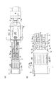
【図1】(a)実施形態の縮径加工装置に於いて筒体を係止爪前方に配置した状態を示す説明図。(b)同図(a)の縮径ダイス、筒体、係止爪の近傍の部分拡大図。
【図2】(a)実施形態の縮径加工装置に於いて係止爪で係止した筒体を縮径ダイスに挿入する状態を示す説明図。(b)同図(a)の縮径ダイス、筒体、係止爪の近傍の部分拡大図。
【図3】(a)実施形態の縮径加工装置に於いて係止爪で係止した筒体全体を縮径した状態を示す説明図。(b)同図(a)の縮径ダイス、筒体、係止爪の近傍の部分拡大図。
【図4】(a)実施形態の縮径加工装置に於いて係止爪で係止した筒体を縮径ダイスから抜き出した状態を示す説明図。(b)同図(a)の縮径ダイス、筒体、係止爪の近傍の部分拡大図。
【図5】(a)実施形態の縮径加工装置に於いて筒体への係止爪の係止を解除した状態を示す説明図。(b)同図(a)の縮径ダイス、筒体、係止爪の近傍の部分拡大図。
【図6】(a)実施形態の縮径加工装置に於いて係止を解除した係止爪を退出する状態を示す説明図。(b)同図(a)の縮径ダイス、筒体、係止爪の近傍の部分拡大図。
【図7】実施形態の縮径加工装置に於ける係止爪の設置部分の正面図。
【図8】実施形態の縮径加工装置に於ける係止爪、スリーブ、押止部を示す部分説明図。
【符号の説明】
1 縮径加工装置
2 縮径ダイス
2a 鍔
2b テーパ部
2c 直線部
3 係止爪
3a 段差部
3b 当接面
3c 係止部
3d、6a、7b 傾斜面
4 スリーブ
4a スリット
5 管状部材
6 支持部
7 押止部
7a 押止片
8 基軸
9 基台
10、11 油圧シリンダー
10a、11a ピストンロッド
100 触媒コンバータ
101 セラミックハニカム構造体
102 膨張マット
103 外筒[0001]
BACKGROUND OF THE INVENTION
The present invention relates to a diameter reducing apparatus for reducing a diameter of a cylinder such as an outer cylinder of a catalyst carrier, for example.
[0002]
[Prior art]
As a related art related to the diameter reduction processing of the outer cylinder of the catalyst carrier, etc., a cylindrical catalyst carrier having an expansion mat wound around the outer periphery is accommodated in a cylindrical outer cylinder, and the catalyst carrier is accommodated in the outer case. The tube is inserted into the swaging die and installed, and the swaging die is inserted into the swaging collar while being in contact with the inner periphery, and the taper is sequentially reduced in diameter along the insertion direction of the swaging collar.
[0003]
[Patent Document 1]
JP-A-8-42333 [Patent Document 2]
Japanese Patent Laid-Open No. 2002-97944
[Problems to be solved by the invention]
By the way, the diameter reduction process of the above-mentioned
[0005]
The present invention is proposed in view of the above problems, and relates to a diameter reduction processing apparatus for reducing the diameter of a cylindrical body such as an outer cylinder of a catalyst carrier, for example. An object of the present invention is to provide a diameter reduction processing apparatus capable of performing processing.
[0006]
[Means for Solving the Problems]
The diameter reduction processing apparatus of the present invention is provided with a diameter reduction die formed with a taper that reduces the diameter in the insertion direction of the cylinder, and is arranged in a circumferential shape to lock the end of the cylinder, and A locking claw that moves in the diameter-reducing direction according to the inner diameter of the diameter die, an advancing / retracting means that moves the locking claw into and out of the diameter-reducing die, and a movement of the locking claw in the diameter-reducing direction of the diameter-reducing die And the latch release means which cancels | releases the latching to this cylinder body end part is provided, It is characterized by the above-mentioned. The locking claw that locks the end of the cylindrical body enters the reduced diameter die, and the locking claw is moved in the reduced diameter direction while reducing the diameter of the cylindrical body according to the inner diameter of the reduced diameter die. When the diameter cylinder is extracted from the diameter reducing die, the locking claw is forcibly moved in the diameter reducing direction by the locking release means to release the locking to the cylinder end, and the locking claw is Exit from inside the reduced diameter die.
[0007]
The advancing / retreating means and the locking releasing means for advancing / retreating the locking claw can be appropriately configured. As will be described later, for example, the advancing / retreating means is constituted by a hydraulic cylinder and a piston rod or the like, or a pressing portion. Thus, it is possible to configure the locking release means by pressing the substantially rear portion of the locking claw from diagonally forward.
[0008]
Further, in the diameter reduction processing apparatus of the present invention, the cylindrical body is an outer cylinder of a ceramic honeycomb structure, and the outer cylinder in which the ceramic honeycomb structure is inserted is locked with the locking claws. The outer cylinder is reduced in diameter. The cylindrical body to be diameter-reduced by the diameter-reducing apparatus of the present invention can be an appropriate cylindrical body, but is an outer cylinder of a ceramic honeycomb structure, and the outer cylinder is integrated with the ceramic honeycomb structure by diameter reduction processing. It is preferable to form a catalytic converter by forming the catalytic converter, and the catalytic converter can be manufactured by an efficient manufacturing process while preventing the ceramic honeycomb structure from being damaged by an appropriate pressing force.
[0009]
DETAILED DESCRIPTION OF THE INVENTION
Below, specific embodiment of the diameter reducing processing apparatus of this invention is described. 1 to 6 are diagrams sequentially showing states of respective steps in the diameter reduction processing apparatus according to the embodiment, FIG. 7 is a front view of an installation portion of a locking claw, and FIG. 8 is a locking claw, a sleeve, and a pressing portion. FIG. 2 to 5, the
[0010]
As shown in FIGS. 1 to 8, the diameter
[0011]
The diameter reduction die 2 of the diameter
[0012]
A plurality of
[0013]
The substantially rear portion of each
[0014]
In addition, the
[0015]
A
[0016]
Both the
[0017]
Next, operation | movement of the diameter reducing
[0018]
First, as shown in FIG. 1, the
[0019]
Thereafter, the
[0020]
Further, as the diameter of the rear end portion of the
[0021]
Thereafter, the
[0022]
Then, the
[0023]
Thereafter, as shown in FIG. 6, the
[0024]
In the above embodiment, the
[0025]
【The invention's effect】
The diameter-reducing apparatus of the present invention has an effect that a precise diameter-reducing process can be performed on a cylindrical body such as an outer cylinder of a catalyst carrier by an efficient manufacturing process. Therefore, for example, when manufacturing a catalytic converter using a ceramic honeycomb structure, the outer cylinder in which the ceramic honeycomb structure is provided can be accurately and efficiently reduced in diameter. The structure is not damaged.
[Brief description of the drawings]
FIG. 1A is an explanatory view showing a state in which a cylindrical body is arranged in front of a locking claw in a diameter reducing apparatus of an embodiment. (B) The elements on larger scale of the diameter reduction die | dye of FIG.
FIG. 2A is an explanatory view showing a state in which a cylindrical body locked by a locking claw is inserted into a reduced diameter die in the reduced diameter processing apparatus of the embodiment. (B) The elements on larger scale of the diameter reduction die | dye of FIG.
FIG. 3A is an explanatory view showing a state in which the diameter of the entire cylinder locked by the locking claw is reduced in the diameter reduction processing apparatus of the embodiment. (B) The elements on larger scale of the diameter reduction die | dye of FIG.
FIG. 4A is an explanatory view showing a state in which a cylindrical body locked by a locking claw is extracted from a reduced diameter die in the reduced diameter processing apparatus of the embodiment. (B) The elements on larger scale of the diameter reduction die | dye of FIG.
FIG. 5A is an explanatory view showing a state in which the locking claw is released from the cylindrical body in the diameter reducing apparatus of the embodiment. (B) The elements on larger scale of the diameter reduction die | dye of FIG.
FIG. 6A is an explanatory view showing a state in which the latching claw that has been unlocked is retracted in the diameter reducing apparatus of the embodiment; (B) The elements on larger scale of the diameter reduction die | dye of FIG.
FIG. 7 is a front view of an installation portion of a locking claw in the diameter reducing apparatus of the embodiment.
FIG. 8 is a partial explanatory view showing a locking claw, a sleeve, and a holding part in the diameter reducing apparatus of the embodiment.
[Explanation of symbols]
DESCRIPTION OF
Claims (2)
Priority Applications (1)
| Application Number | Priority Date | Filing Date | Title |
|---|---|---|---|
| JP2003208675A JP4301552B2 (en) | 2003-08-25 | 2003-08-25 | Diameter reduction processing equipment |
Applications Claiming Priority (1)
| Application Number | Priority Date | Filing Date | Title |
|---|---|---|---|
| JP2003208675A JP4301552B2 (en) | 2003-08-25 | 2003-08-25 | Diameter reduction processing equipment |
Publications (2)
| Publication Number | Publication Date |
|---|---|
| JP2005069016A JP2005069016A (en) | 2005-03-17 |
| JP4301552B2 true JP4301552B2 (en) | 2009-07-22 |
Family
ID=34401861
Family Applications (1)
| Application Number | Title | Priority Date | Filing Date |
|---|---|---|---|
| JP2003208675A Expired - Fee Related JP4301552B2 (en) | 2003-08-25 | 2003-08-25 | Diameter reduction processing equipment |
Country Status (1)
| Country | Link |
|---|---|
| JP (1) | JP4301552B2 (en) |
-
2003
- 2003-08-25 JP JP2003208675A patent/JP4301552B2/en not_active Expired - Fee Related
Also Published As
| Publication number | Publication date |
|---|---|
| JP2005069016A (en) | 2005-03-17 |
Similar Documents
| Publication | Publication Date | Title |
|---|---|---|
| CA2521759A1 (en) | Stent delivery system with securement and deployment accuracy | |
| CN100387804C (en) | Expansion device for expanding pipe | |
| US7024908B2 (en) | Fatigue enhancement of material surrounding openings in workpieces | |
| KR930020041A (en) | Fastener assembly | |
| CN102177320B (en) | Method for producing an exhaust gas conducting device and tool therefor | |
| US20150232195A1 (en) | Ram air turbine actuator | |
| US12392214B2 (en) | Liner hanger slip retention system and method | |
| EP0112853A1 (en) | Tube expander | |
| EP1727476A1 (en) | A wound retractor device | |
| JP4301552B2 (en) | Diameter reduction processing equipment | |
| US5465855A (en) | Telescoping crane arm | |
| JP6638081B2 (en) | Tire building drum and method for operating a tire building drum | |
| JP4098384B2 (en) | Pipe fitting | |
| EP1001132A3 (en) | Telescoping/release joint | |
| US5309968A (en) | Tire chain and the method of mounting it | |
| US6488303B1 (en) | Collapsible suspension slider pin | |
| JP4011451B2 (en) | Backward extrusion method and backward extrusion device | |
| JP4036501B2 (en) | Pipe fitting | |
| US20060117830A1 (en) | Transition forming machine | |
| US20180129242A1 (en) | Locking mechanisms for ram air turbine actuators | |
| JPH05104142A (en) | Expansion drum | |
| JPH0113936B2 (en) | ||
| JP3941130B2 (en) | Belt winding device | |
| JP4599531B2 (en) | Segment ring shape holding method and shape holding device | |
| JP2002087707A (en) | Method and device for mounting roll-like winding material |
Legal Events
| Date | Code | Title | Description |
|---|---|---|---|
| A621 | Written request for application examination |
Free format text: JAPANESE INTERMEDIATE CODE: A621 Effective date: 20060807 |
|
| A977 | Report on retrieval |
Free format text: JAPANESE INTERMEDIATE CODE: A971007 Effective date: 20090409 |
|
| TRDD | Decision of grant or rejection written | ||
| A01 | Written decision to grant a patent or to grant a registration (utility model) |
Free format text: JAPANESE INTERMEDIATE CODE: A01 Effective date: 20090415 |
|
| A01 | Written decision to grant a patent or to grant a registration (utility model) |
Free format text: JAPANESE INTERMEDIATE CODE: A01 |
|
| A61 | First payment of annual fees (during grant procedure) |
Free format text: JAPANESE INTERMEDIATE CODE: A61 Effective date: 20090420 |
|
| FPAY | Renewal fee payment (event date is renewal date of database) |
Free format text: PAYMENT UNTIL: 20120501 Year of fee payment: 3 |
|
| R150 | Certificate of patent or registration of utility model |
Ref document number: 4301552 Country of ref document: JP Free format text: JAPANESE INTERMEDIATE CODE: R150 Free format text: JAPANESE INTERMEDIATE CODE: R150 |
|
| FPAY | Renewal fee payment (event date is renewal date of database) |
Free format text: PAYMENT UNTIL: 20130501 Year of fee payment: 4 |
|
| R250 | Receipt of annual fees |
Free format text: JAPANESE INTERMEDIATE CODE: R250 |
|
| FPAY | Renewal fee payment (event date is renewal date of database) |
Free format text: PAYMENT UNTIL: 20130501 Year of fee payment: 4 |
|
| R250 | Receipt of annual fees |
Free format text: JAPANESE INTERMEDIATE CODE: R250 |
|
| R250 | Receipt of annual fees |
Free format text: JAPANESE INTERMEDIATE CODE: R250 |
|
| R250 | Receipt of annual fees |
Free format text: JAPANESE INTERMEDIATE CODE: R250 |
|
| R250 | Receipt of annual fees |
Free format text: JAPANESE INTERMEDIATE CODE: R250 |
|
| R250 | Receipt of annual fees |
Free format text: JAPANESE INTERMEDIATE CODE: R250 |
|
| R250 | Receipt of annual fees |
Free format text: JAPANESE INTERMEDIATE CODE: R250 |
|
| R250 | Receipt of annual fees |
Free format text: JAPANESE INTERMEDIATE CODE: R250 |
|
| LAPS | Cancellation because of no payment of annual fees |